Endoscope Cleaning & Maintenance Workshop
|
|
|
- Susanna Cummings
- 6 years ago
- Views:
Transcription
1 Endoscope Cleaning & Maintenance Workshop
2 Table of Contents Introduction 1 CHAPTER 6 CHAPTER 1 Programme 2 Manual cleaning of removable parts 29 Disinfection of removable parts 31 CHAPTER 2 History of Olympus endoscopy 3 CHAPTER 7 Endoscope washing machines 34 CHAPTER 3 Nomenclature of endoscopes 4 CHAPTER 8 Service department protocols 35 Routine servicing of endoscopes 36 CHAPTER 4 Structure and function of endoscopes 5 Service agreements 38 Preventative maintenance visits 39 Fiberscope optical system 6 Video scope imaging system 7 Endoscope inspection 8 CHAPTER 9 Endoscopic accessories 40 Accessory codes 40 CHAPTER 5 Cleaning and disinfection of endoscopes 11 Pre-cleaning 12 Leak testing 15 Failed leak tests 17 Endoscope compatibility 42 Electrosurgical accessories 42 Reprocessing protocol 46 Repairs warranties of accessories 49 Construction of hinged forceps 50 Brushing of internal channels 18 Manual flushing of internal channels 21 Manual disinfection of endoscopes 24 Terminal flush / alcohol flush 27 Storage of endoscopes 27 CHAPTER 10 Cleaning and disinfection of bronchoscopes 51 Pre-cleaning 52 Leak testing 53 Brushing of internal channels 53 Flushing of internal channels 54
3 Welcome to Olympus T hank you for attending the Olympus Australia Endoscope Cleaning and Maintenance Workshop. We trust that you will enjoy this opportunity to learn more about all aspects of care and maintenance of endoscopic equipment. Our aim is to keep these sessions as informal as possible and your interaction will be actively encouraged. If you have any questions or concerns throughout today, please do not hesitate to raise them with the facilitator of your session. Again, thank you for your attendance, and welcome to Olympus Australia. 1
4 Chapter 1 Programme Registration Introduction History of endoscopy Structure and function of endoscopes Morning tea Cleaning and disinfection of endoscopes Includes: Pre-cleaning Leak testing Brushing Manual flushing Disinfection / sterilisation Alcohol flushing Storage Lunch Care and maintenance of endoscopic accessories Discussion / presentation of certificates Hands on demonstrations Close 2
5 Chapter 2 History of Olympus Endoscopy 1910 Oesophageal tube 1919 Olympus established in Tokyo as Takachihi Seisakuho 1921 Olympus registered as trademark 1932 Schindler semi flexible gastroscope 1948 Development of Gastrocamera commence 1949 Company renamed Olympus Optical Co., Ltd 1950 First Gastrocamera (GT-1) introduced at Japan Surgical Conference 1963 Gastrocamera with fiberscope introduced 1983 OES immersible endoscopes introduced 1985 EVIS-1 first generation video endoscopy system released 1989 EVIS100 series video endoscopy system released 1997 EVIS 140 series video endoscopy system released 1997 Olympus Australia established 2000 EVIS EXERA 160 and 145 series video endoscopy systems released 2002 Olympus Australia relocates to new head office in Mount Waverley, Victoria 3
6 Chapter 3 Nomenclature of Endoscopes Control body Biopsy port Distal tip Insertion tube Universal cord Light guide plug 4
7 Chapter 4 Internal Structure & Function of Endoscopes B oth fiberoptic and video endoscopes share the same basic design principles and, to a large extent, the same mechanical construction. The main difference between the two endoscopes is the system that transmits the image. The fiberoptic endoscope utilises optical fibres and the video endoscope, advanced CCD (charged coupled device) technology. Both systems require a light guide and a complex objective lens system at the distal end to focus the image. 5
8 Fiberscope Optical System M any thousand (often in excess of 45,000) optical fibres are arranged into an ordered pattern to form a coherent image guide fibre bundle. The fibres in coherent bundles are arranged at each end in a common matrix, i.e., each single fibre is held in the same place at either end but is free to flex in the middle section. Thus a complete image can be transferred over a long distance, with each individual fibre carrying a small component part of the image. The degree of ordering of a coherent optical fiber bundle is vital to the quality of the image it transmits - the more perfect the ordering, the better the image quality. Also, of course, broken fibers in the bundle will mean the loss of one component part of the final image, although in practice a relatively small number of broken fibers (less than 25) will give a negligible effect on the image resolution (quality) of a modern fiber scope. 6
9 Video Scope Imaging System T he CCD (charged coupled device) used in the video endoscope, is a solid-state microchip used for image sensing. The photo-sensitive surface of the chip is divided into an array (rows and columns) of cells, each able to directly convert the light focused upon it into electrical charges (electrons). These cells are more commonly called pixels, a name derived from picture element. A pixel represents the limit of image resolution and is the basic building block used to re-create an electronic image. The electrical charge produced at each pixel corresponds to the intensity of the light falling on that particular pixel. By reading the charge developed at each pixel sequentially, the image focused on the CCD surface is turned into an electronic signal which can, after sophisticated processing, be accurately reproduced on a TV (video) monitor. T he CCD in the video endoscope produces coded, electronic data which must be decoded before it can be viewed. The electronic signal is passed down wires within the endoscope to an image processor where it is decoded and transmitted to a TV monitor for viewing as shown below: 7
10 Endoscope Inspection A ll instruments should be inspected as frequently as possible and ideally, before each use. Should faults or abnormalities be suspected, the instrument should not be used and the Technical Service Centre contacted on a) Inspection of the Insertion Tube Inspect the surface of the insertion tube, both visually and by running your fingertips over the whole length. Check for dents, protruding objects or other irregularities. b) Inspection of the Bending Mechanism Check that the angulation locks stabilise the tips of the scope when engaged and allow free movement of the control knobs when released ( F or free position). Operate the angulation controls slowly to their limit in each direction, checking for smooth operation. Check the degree of angulation against the standard taken when the instrument was new. Check the bending section rubber for signs of wear and physical damage. (Never bend or twist the bending section by hand). 8
11 c) Inspection of the Optical System Using clean gauze moistened in 70% alcohol, clean the lens surface at the distal tip of the insertion tube (for fiberoptic scopes, also clean the eyepiece). Do not use abrasive cleaners as damage to the lens coating may occur. Attach your scope to the light source and switch on. For video scopes, attach to the video processor and switch on. Check the image for clarity using an object approximately 15mm from the distal tip. With fiberscopes, record the number of broken fibres (black dots) on the image. A sudden increase in these may indicate damage to the instrument. d) General Inspection Check the light output from the tip of the scope to ensure the light guides are functioning. For fiberscopes used with cameras or video converters, check the contact pins surrounding the eyepiece lens. Any deposits should be cleaned using a cotton bud moistened in 70% alcohol. All other parts of the instrument should be visually checked for signs of wear or damage. 9
12 A leak test on your endoscope should be preformed prior to presoaking (at the beginning of your list) and prior to cleaning your scope once a procedure is complete. This is one of the most vital preventative measures to ensure major damage does not occur to an endoscope. Fluid ingress into the optical bundle of a fiberscope or a CCD chip of a video scope will cause major damage, resulting in high cost repairs. Correct leakage testing will detect points on the endoscope where fluid could enter and must therefore, be performed as frequently as possible, and certainly before and after each session. The leak test procedure is described in detail on page 15 of this manual. 10
13 Chapter 5 Cleaning and Disinfection of Endoscopes C leaning and disinfection of endoscopes can be broken down into the following stages: 1. Pre-cleaning page Leak testing page Brushing page Manual flushing page Rinsing page High level disinfection / sterilisation page Rinse after disinfection page Alcohol flush page 27 (Olympus has produced a cleaning video & poster that details the entire cleaning process of your scope, please enquire after the workshop). 11
 Prepare a container of detergent solution.")
 Place the distal end of the insertion tube in the detergent solution and aspirate detergent")
14 Pre-cleaning P erformed at the bedside immediately after each examination. (1) Prepare a container of detergent solution. (2) Wipe the entire insertion tube with a clean, lint-free cloth soaked in detergent solution. (3) Place the distal end of the insertion tube in the detergent solution and aspirate detergent solution until clear return is seen in suction tubing. Then aspirate air for 10 seconds. 12
 Remove the air/water button and replace with the AW channel cleaning button (MH-948).")
15 CAUTION: Monitor the suction bottle carefully to be sure that it does not overflow, as this could result in damage to the suction pump. (4) Remove the air/water button and replace with the AW channel cleaning button (MH-948). (5) Feed water using the AW channel cleaning button by depressing the silver button, feed air by releasing the silver button. WARNING: D o not use the AW channel cleaning adaptor for patient examinations as it will cause continuous insufflation and result in patient injury. The MH-948 AW channel cleaning adapter does not require lubrication. Lubricants (e.g. water soluble brands and silicone oil) can cause swelling of the valve rubber parts that will affect valve performance or damage the valve. To prevent blocking the air/water nozzle, always use the AW channel cleaning adapter when cleaning the air/water channel after each case. 13
 Detach the AW channel cleaning adapter, suction valve and biopsy valve from the endoscope and reprocess as described in chapter 6, Procedures for Cleaning, Disinfection and Sterilisation of")
16 (6) Turn OFF the light source. Turn OFF the video processor. (If further cases follow immediately after, the light source CAN be left running). (7) Detach the AW channel cleaning adapter, suction valve and biopsy valve from the endoscope and reprocess as described in chapter 6, Procedures for Cleaning, Disinfection and Sterilisation of Removable Parts. (8) Disconnect the water bottle from the endoscope. (9) Disconnect the suction tube from the suction connector. (10) Disconnect the video scope cable from the endoscope. Remove the endoscope from the light source. Replace the waterproof cap (MH- 553). (11) Transport endoscope and accessories carefully to your clean up area. 14
17 Leak Testing T his should be preformed PRIOR to pre-soaking your scopes (at the beginning of a list) and PRIOR to cleaning your scope after procedure. The sequence for performing a leak test is as follows. 1. Attach the water resistant cap MH-553 to the endoscope. MH Set the Maintenance unit (MU-1) or light source to ON and air setting to HIGH. Attach the leak test cable (MB-155) to the air source. Olympus MB-155 Leak-tester Check that sufficient air emits from the leak tester mouthpiece by inserting a dry finger into the pin. Verify that the air emitted contains no moisture. 15

18 3. Attach the leak test cable to the ETO valve of the endoscope. MB-155 MH-553 Water Leakage mouthpiece 4. Confirm that the bending section of the endoscope is swollen. 5. Immerse the entire scope into a basin of water. Observe for bubbling consistent with leaks keeping in mind some settling of trapped air will occur. Angulate distal tip in all directions to check rubberised section is free of small holes. 16
19 6. Remove the endoscope from the basin. Remove the leak test cable from the air source and wait 30 seconds for the bending section to deflate. 7. Disconnect the leak tester from the endoscope. NB: Do not detach the leak test cable from the endoscope under water. Failed Leak Tests C ontinuous bubbling from the endoscope may indicate the presence of a leak. If a leak is suspected, the following procedure applies; Keep the leak test cable (MB-155) attached to the running air source. Perform all steps as described on the following pages for manual cleaning and flushing. If possible, disinfect the endoscope, with the leak tester attached and running, in disinfectant solution. If manual disinfection is not possible contact the Olympus Service Centre on for further instructions. 17
20 Brushing of Internal Channels 1. Fill a basin with water and low foaming detergent solution to the temperature and concentration recommended by the detergent manufacturer. Use a basin which is deep enough to allow the endoscope to be completely immersed. 2. Immerse the endoscope and transfer the AW channel cleaning adapter, air/water and suction valves, and biopsy valve into the basin with detergent solution. 3. With the endoscope immersed, use a soft brush or lint-free cloth to thoroughly brush and wipe all outside surfaces of the endoscope. Pay particular attention to the air/water nozzle opening and ensure that all surfaces of the distal end are cleaned thoroughly. 4. Brush the instrument/suction channel, suction cylinder and instrument channel opening according to the following procedure: Grip the Channel Cleaning Brush BW-20T 3cm from the bristles. (NB: Please refer to your scopes manual for the cleaning brush best suited to your model). Insert it at a 45 angle into the opening located in the base of the suction valve housing. 18

21 Using short stokes, feed the brush through the insertion tube until it emerges from the distal end of the endoscope. Clean off the bristles with your fingertips. Carefully pull the brush back through the channel. Clean off the bristles again. If debris remains after brushing repeat until all debris is removed. Insert the channel cleaning brush straight into the suction valve housing into the opening located in the back of the housing. Using short strokes, feed the brush through the universal cord until it emerges from the suction connector on the light guide connector. Clean off the bristles with your fingertips. Carefully pull the brush back through the channel. Clean off the bristles again. If debris remains after brushing repeat until all debris is removed. Insert the channel cleaning brush into the biopsy valve housing. Using short stokes, feed the brush through the insertion tube until it emerges from the distal end of the endoscope. Clean off the bristles with your fingertips. Carefully pull the brush back through the channel. Clean off the bristles again. If debris remains after brushing repeat until all debris is removed. Insert the channel opening cleaning brush (MH-507) into the suction valve cylinder until approximately half of the brush head is inside the opening. 19

22 Rotate the brush once and then pull it out. Wash the bristles. Repeat for the air/water valve housing and the biopsy port. 20

23 Manual Flushing of Internal Channels 1. Attach the suction cleaning adapter (MH-856) to the instrument channel port. Reattach the suction tubing to the suction outlet of the endoscope. 2. Attach the suction cleaning adapter to the instrument biopsy channel port on the Endoscope. 3. Immerse both the endoscope s distal end and the weighted end of the suction cleaning adapter in the detergent solution. 4. Cover the suction valve cylinder with your finger and aspirate detergent solution for approximately 30 seconds. 5. Turn OFF the suction pump. 6. Disconnect the suction tube and the suction cleaning adapter. Leave to soak in the detergent solution, then reprocess as described in Chapter 6: Manual Cleaning of Removable Parts. 21
 and 30cc syringe to flush the air/water channels with detergent solution.")

24 7. Attach the Channel Plug (MH-944). Depress cover straight and slide straight towards the i 8. Attach Injection Tube (MH-946) and 30cc syringe to flush the air/water channels with detergent solution. NOTE: The All-Channel Irrigator (CW-3) cannot be used on 140 / 145 / 160 series scopes. Adaptors for the MH-946 are available for older models please enquire with Olympus. 9. Attach 30 cc Luer Lock syringe to the injection tube s air/water channel port. Inject 90mls of detergent solution into the air/water channel to flush the channels. 10. Move syringe from Air/Water port to suction channel and inject 90mls of detergent solution. 11. Repeat the entire flushing process using 90 mls of filtered water in both channels. 22
25 12. Repeat the entire flushing process again with 90 mls of air in both channels. 13. If you have a CF-100 / 130 series colonoscope with an auxiliary water channel, attach the corresponding cleaning tube to the channel opening and inject detergent 30 mls of detergent solution, then 30 mls water, then 30 mls air into the channel. 14. If you have a 160 series colonoscope with an auxiliary water channel, attach the corresponding cleaning tube to the channel opening and inject detergent 90 mls of detergent solution, then 90 mls water, then 90 mls air into the channel. 15. If injecting into a duodenoscope forceps raising channel, use a 2 or 5 ml syringe only and inject slowly with 15 mls of detergent solution, 5 mls water and 10 mls air. Duodenoscope Forceps Raiser 160 Series Colonoscope with an auxiliary water channel 15. Disconnect the channel plug and injection tube from the endoscope. 16. Finally inspect the surface of the scope for remaining debris if debris is present, we recommend repeating manual cleaning cycle. 17. Rinse the entire endoscope by immersing in a basin of fresh filtered water. The endoscope is now ready for reprocessing via washing machine or manual procedures as detailed on page
26 Manual Disinfection R efer to this section if no Washing Machine is used in your suite. If the Endoscope was not reprocessed immediately following the last examination, it may be necessary to soak the instrument in detergent for up to a maximum of 10 hours. Following this, manual cleaning should be repeated prior to disinfection to ensure that all debris is removed. Please refer to the Manual Cleaning section in this handbook. All disinfection steps should be done with the endoscope and all equipment completely immersed. If the equipment is connected or disconnected while not immersed disinfectant solution may not adequately contact all surfaces of the equipment. The effectiveness of disinfection may be reduced. 1. Fill a basin with disinfectant solution at a temperature and concentration according to the instructions on the manufacturer s label. Use a basin that is at least 40cm by 40cm (16 by 16 ) in size and deep enough to allow the endoscope to be completely immersed. 2. Attach the channel plug and the injection tube to the endoscope, and immerse completely in the basin with disinfectant solution. 3. With the injection tube s intake in the disinfectant solution, use the 30cc syringe to flush the air/water channel with 90mls of disinfectant solution, and the suction channel with 90mls disinfectant solution to all channels and expel all air. 4. If auxiliary water channels or forceps raising channels are present, attach the appropriate cleaning tube and inject disinfectant solution into this channel also. Refer to pages 23 & 23 for volumes. 24
27 5. With the endoscope and the channel plug and injection tube completely immersed in the disinfectant solution, disconnect the channel plug and injection tube from the endoscope. Leave all three to soak in the disinfectant solution. * Disconnect the channel plug and injection tube from the endoscope only while they are completely immersed. Disconnecting when not immersed may allow air to be drawn into the channels and will reduce the effectiveness of the disinfection. * Should air bubbles adhere to the surfaces of the endoscope, channel plug, or injection tube, remove these using a clean, soft lint-free cloth. * Cover the disinfectant basin with a tight fitting lid to minimize the release of disinfectant vapour. * Soak the equipment for the amount of time and at the temperature recommended by the disinfectant manufacturer. It is recommended to use a timer to check the correct soaking time. 6. Re-attach channel plug and injection tube. Flushing with Air: Using the channel plug and the injection tube, flush air through the air/water and suction channels as follows: 1. Before removing the endoscope from the disinfectant solution, connect the channel plug and injection tube to the endoscope. 2. Remove the injection tube intake from the disinfectant solution. 3. Attach the 30cc syringe to the injection tube s air/water channel port and flush the air/water channel with 90mls of air. 4. Attach the 30cc syringe to the injection tube s suction channel port and flush the suction channel with 90mls of air. 25
28 5. Inject air into any auxiliary channels / forceps raiser channels if present. Refer to pages 23 & 23 for volumes. 6. Remove the endoscope from disinfection solution. Rinsing with Water: 1. Immerse the endoscope, channel plug, and injection tube in water (refer your hospital guidelines for water specifications required). Use sterile lint-free cloth to thoroughly rinse all external surfaces. 2. Connect the injection tube to the endoscope. With the injection tube intake immersed in sterile water and using the 30 cc syringe, flush the air/water channel and the suction channel with 90mls of sterile water respectively. Flush any auxiliary channels / forceps raiser channels if present with sterile water. Refer to pages 23 & 23 for volumes. 3. With the channel plug and injection tube connected to the endoscope, remove the equipment from the sterile water. 4. Flush with air to expel sterile water from the air/water and suction channels. 5. Use lint-free cloth to thoroughly wipe dry the external surfaces of the endoscope, channel plug and injection tube. 6. Inject air into any auxiliary channels / forceps raiser channels if present. Refer to pages 23 & 23 for volumes. 26
29 Terminal Cleaning / Flushing: Immediately before storing your endoscope at the completion of your list flush channels with alcohol as follows: 1. Immerse the injection tube intake in 70% isopropyl alcohol or 70% ethyl alcohol. Using the 30 cc syringe, flush the air/water channel and the suction channel with 60 mls and 90 mls respectively. 2. Remove the injection tube intake from the alcohol. Flush the air/water channel and the suction channel with 60 mls & 90 mls of air respectively. Use a lint free cloth moistened with 70% isopropyl alcohol or 70% ethyl alcohol to thoroughly wipe the external surfaces of the endoscope, channel plug and injection tube. Storage of Endoscopes: Your storage cabinet should be: Clean Dry Well ventilated and maintained at room temperature Do not store your endoscope: In direct sunlight At high temperatures / humidity Where exposed to X-rays In the carrying case. Use the carrying case only for shipping. Routinely storing the endoscope in an unventilated case may encourage the growth of microorganisms. These factors can damage your endoscope or present an infection control risk. 27
30 Detach all removable parts of the endoscope. By removing the air/water valve, biopsy valve and suction valve, air will circulate through the internal lumens of the endoscope and assist in drying. Before storage: Thoroughly dry all parts of the endoscope (especially all internal lumens, distal ends and electrical contacts) and accessories. Use a cotton swab moistened with 70% ethyl or isopropyl alcohol to carefully remove any film covering the surface of the objective lens and light guide glass on distal end. Place the endoscopes angulation locks in the F (or free) position. Hang the endoscope in your storage cabinet with the distal tip hanging freely. Please ensure that insertion tube hangs as straight as possible. 28
31 Chapter 6 Manual Cleaning of Removable Parts 1. Immerse the removable parts in a basin of detergent solution, prepared according to the manufacturer s instructions. Uncap the semi-disposable biopsy valve before immersing CAUTION: Please ensure items immersed in detergent solution do not contact each other, which can lead to scratched seals on the air/water valve and AW channel cleaning adapter from the brushes etc. Valves and Buttons 2. Using a soft clean brush, sponge or lint-free cloth, meticulously clean the outer surfaces in the detergent solution. Depress and release the pistons of the air/water valve, suction valve and AW Cleaning adapter to ensure the detergent solution contacts all crevices and surfaces of the valves. 3. Using the channel cleaning brush, thoroughly brush the openings of the suction valves and the air/water valves until no debris can be seen. Again, clean the bristles and crevices of the brush while immersed in the detergent solution. 4. Using a 30 cc syringe, flush the interior and recessed parts of the biopsy valve while immersed. 5. Soak all components for the amount of time and at the temperature recommended by the manufacturer (or your hospital). 29
32 6. Remove the parts from the detergent solution and place in Ultrasonic cleaner. 7. Ultrasonically clean the valves and buttons at 40 khz for 5 minutes. 8. Rinse the valves and buttons in clean water. Cleaning Attachments 1. Immerse the removable parts in a basin of detergent solution, prepared according to the manufacturer s instructions. 2. Using a soft clean brush, sponge or lint-free cloth, meticulously clean the outer surfaces in the detergent solution. Clean the bristle sections of the cleaning brushes thoroughly while immersed. 3. To clean the suction cleaning adapter, attach the 30 cc syringe to the biopsy valve connector and flush the tube thoroughly with detergent solution. 4. Soak all components for the amount of time and at the temperature recommended by the manufacturer (or your hospital). 5. Ultrasonically clean the channel cleaning brushes for 5 minutes at 40 MHz. 6. Remove the parts from the detergent solution and place in clean water. 7. Attach the syringe to the suction cleaning adapter and flush the tube with clean water. 8. Remove all accessories from the water. 9. Attach the 30 cc syringe to the suction cleaning adapter and flush air to thoroughly dry the inside of the tube. 10. Use a clean, lint-free cloth to thoroughly dry the parts. 30
33 Disinfection of Removable Parts 1. Prepare a basin of disinfection solution according to the manufacturer s instructions. 2. Immerse accessories into basin. 3. While immersed, depress and release the pistons of the valves and the AW channel cleaning adapter to ensure the disinfectant solution contacts all internal surfaces of the valves. Use the 30cc syringe to flush the openings and crevices with disinfection solution to remove all air bubbles. 4. Rub the bristles of the cleaning brushes to ensure all air bubbles are removed. 5. Using a 30 cc syringe, flush the interior and recessed parts of the biopsy valve while immersed. 6. Attach the 30 cc syringe to the suction cleaning adapter and flush the tube with the disinfectant solution to ensure that all air bubbles are expelled. 7. Using a clean, lint-free cloth, wipe away any air bubble adhering to surfaces. 8. Soak the parts for the amount of time, and at the temperature recommended by the disinfectant manufacturer. Note: Accessories with the colour GREEN are autoclavable. If autoclaving facilities are available, these items can be reprocessed in this manner. 31
34 Rinse after Disinfection O nce removed from the disinfectant solution, the parts must be thoroughly rinsed with sterile water to remove any disinfectant residue. If sterile water is not available, fresh tap water, or water which has been processed (e.g. filtered) to improve its microbiological quality may be used instead. Please consult your hospitals infection control committee for further information. If non-sterile water is used for rinsing, the parts must be wiped and flushed with 70% ethyl alcohol or 70% isopropyl alcohol as follows: Rinse with Sterile Water 1. Remove the suction cleaning adapter from the basin of disinfectant solution and attach the 30 cc syringe. Flush with air to expel all disinfectant solution. 2. Remove parts from the disinfectant solution and immerse in a basin of sterile water. 3. While immersed in the sterile water, depress and release the pistons of the valves and AW channel cleaning adapter. 4. Attach the 30 cc syringe to the suction cleaning adapter and flush sterile water through the tube. 5. Gently agitate the parts to thoroughly rinse. 6. Remove the parts from the sterile water. 7. Attach the 30 cc syringe to the suction cleaning adapter and flush air to dry the inside of the tube. 8. Thoroughly dry the parts with a lint-free cloth. 32
35 Flush with Alcohol 1. Prepare a small container of 70% isopropyl or ethyl alcohol. 2. Attach the 30 cc syringe to the suction cleaning adapter and flush 70% isopropyl or ethyl alcohol through the tube. 3. Immerse all parts in the alcohol. While immersed, depress and release the pistons of the valves and AW channel cleaning adapter. 4. Remove the parts from the alcohol. 5. Attach the 30 cc syringe to the suction cleaning adapter and flush air to thoroughly expel all alcohol from inside the tube. 6. Using a clean lint-free cloth, thoroughly dry the parts. 33
36 Chapter 7 Endoscope Washing Machines P lease refer to your manufacturers instruction manual for any further information regarding endoscope washers. 34
37 Chapter 8 Service Department Protocols (i) Your Supplies department should be made aware that the equipment needs to be returned for repair and an official order will need to be raised. (if applicable) (ii) To Book your repair, call the Toll free Olympus Customer Service hotline on Have the following information available when you call: Your Organisation and department. Your contact details including phone, fax and address. The product model and serial number. A detailed description of the reported fault with the equipment. Any special requests, if required. Our friendly Customer Service staff will immediately enter your repair requirements into the Service Centre system and issue you with a SERVICE REQUEST FORM. Keep your service request form as a reference. You will be required to quote the information on this form when making a query with the service centre. Quoting this reference number will expedite your query as it allows immediate access to your repair records. Enclose a copy of your SERVICE REQUEST FORM, with the equipment being returned to the Service Centre. 35
38 Please minimise any accessories that are being sent back to the Service Centre, unless it is essential or defective. Why? A Quotation will be completed and delivered promptly to your organisation. Olympus is able to track and provide feedback at all times on your repair. Most importantly, your equipment will be back with you sooner! (iii) Ensure equipment is properly packed use the original manufactures case, as it is the best method of storage when despatching. (iv) (v) A declaration of contamination status should always be enclosed. The form mentioned above can also be used to declare this. It is a requirement of Australian Standard AS/NZS 4187:2003 that disinfection protocols are carried out on all medical equipment sent in fro repair. If this is not possible, the items must be returned in an appropriate biohazard bag. Olympus Australia has the facilities of correctly disinfect these items upon receipt. (Charges for disinfecting equipment apply) IMPORTANT No repair work can proceed until we receive your confirmation, with a valid purchase order no. and signed Service Quotation (N/A to customers with valid service contracts) (vi) (vii) Upon receipt of the hospital s signed authorisation, the repair will commence and we will endeavour to return the equipment within our turnaround target time. At the time of authorisation we will, if so requested, (subject to availability) endeavour to supply you with a loan instrument. 36
39 (viii) On completion of repair, the equipment will be dispatched back to you and the loan equipment will need to be returned to your local Olympus agent as soon as possible. Our Policy of Quality Service O lympus policy has always been to return instruments after repair without any operating faults to ensure that our customers achieve maximum up-time. This is why, when you send an instrument for repair specifying air blockage you will sometimes receive a report detailing that we have adjusted the angulation system, replaced a worn bending section rubber, etc. We hope you will agree that this is a sensible policy, operated in the best interests of our customers. If you ever have any questions regarding your repair, please contact our Customer Service Hotline on and we will assist you with your enquiry. Routine Servicing - Flexible Endoscopes W e strongly recommend that flexible endoscopes be returned for routine servicing at least once a year, ideally, every six months or quarterly if the scopes usage is particularly high. 37
40 What Does a Routine Service Cover? S ervice requirements differ depending on the model of instrument. Typically, a routine service covers: (i) (ii) (iii) (iv) (v) (vi) (vii) Incoming fault diagnosis inspection Angle wire tension adjustment Angle radius adjustment Bending section rubber replacement Lubrication and replacement of perishable components Full functional check Full leak test Comprehensive Service Agreements O lympus offers a competitively priced service agreement designed to help protect your Olympus equipment investment. Each plan can be customised to meet specific needs and budgets. Performance Reporting & Analysis Cover your equipment with our premium options and receive onsite performance reports and analysis of your Olympus equipment on a regular basis. Make informed decisions on capital purchases and maintenance options based on operational data on your equipment fleets performance to date within its product life cycle. 38
41 Peace of mind is critical. Having an effective service agreement in place for your Olympus equipment provides you with true peace of mind. Each agreement is designed to eliminate the risk of excessive service expenses and even costlier downtime. Maximise repair savings and control service costs Maximise uptime Improve efficiency Your Support Network When you employ the power of Olympus Service, you employ the strength of a full-service support network staffed by highly experience Olympus equipment specialists. Whenever you need them, the following professionals are available on a local and regional level: Customer Service Representatives Sales Specialists Olympus Repair Technicians National Service Management Field Service Engineers Application Specialists You ve made a substantial investment in Olympus. Make sure it stays protected with Olympus Service. For more information please call your local Olympus Representative, alternatively contact our customer service team on or info@olympus.com.au. 39
42 Chapter 9 Endoscopic Accessories How to Read Names of Flexible Accessories A ll Olympus flexible accessories are given code references from which they can be identified. Example: FB - 25 K - 1 (1) (2) (3) (4) 1. The first two letters in the code indicate the Endotherapy accessory s model name. FB BC FG FS IE PW SD CD FD KD NM BW HX PR SB CC PBD B BML M NA Biopsy Forceps Cytology Brush Grasping Forceps / Retrieval Basket Surgical Scissors / Suture Cutting Forceps Magnetic Extractor Washing Pipe Electrosurgical Snare / Polypectomy Snare Coagulation Electrode / Heat Probe Hot Biopsy Forceps Sphincterotome / Diathermic Cutter Injection Needle Brush For Channel Cleaning Clip Fixing Device / Ligating Device ERCP Cannulae Suction Biopsy Unit Curette Biliary Stent Balloon Catheter Mechanical Lithotriptor Measuring Device Aspiration Biopsy Needle 40
43 2. The digit(s) in the middle indicates the serial number of the Endotherapy accessory type. 3. The final letter in the code indicates the working length of the insertion portion. B = 950 mm Q = 1,950 mm C = 1,050 mm R = 2,050 mm D = 1,150 mm S = 2,150 mm E = 1,200 mm T = 2,200 mm F = 1,250 mm U = 2,300 mm G = 1,300 mm V = 2,400 mm H = 1,400 mm W = 2,500 mm J = 1,450 mm Z = 3,000 mm K = 1,500 mm ST = 500 mm L = 1,650 mm SW = 650 mm M = 1,700 mm SX = 700 mm N = 1,800 mm LB = 4,000 mm P = 1,900 mm LD = 5,000 mm F or products with a rotating function R is added following the working length code. I indicates the instruments compatibility with the refined reprocessing protocol. So, for example, FB-25K-1 is a Biopsy Forceps 1,550 mm long, and the FG- 44NR is a rotatable grasping forceps with the working length of 1,800 mm. 41
44 Endoscope Compatibility (Colour Coding) A s the design of endoscopes and their accessories becomes more sophisticated, it is increasingly important that all accessories are checked for compatibility with Endoscope before use. Olympus Endo-Therapy products have colour coded handles matching the channel openings of Olympus endoscopes. This colour coding is a visual reference to the endoscope s instrument channel diameter. Therefore, by matching an accessory s colour coded handle to the channel opening colour coding, the correct accessory can be quickly and easily identified. The following table demonstrates colour-to-channel size compatibility: White Violet Blue Green Yellow Orange Pink 1.2 mm 1.7 mm 2.0 / 2.2 mm 2.6 mm 2.8 / 3.2 mm 3.7 / 4.2 mm 5.0 / 5.5 mm Electro-Surgical Accessories Electro-surgery which can be performed using an Endoscope includes polypectomy, sphincterotomy, hot biopsy, haemostasis and others. Before each operation, the electro-surgical system should be tested according to the instruction manual supplied with the diathermy unit. Should the slightest irregularity or abnormality be suspected, do not use the equipment. 42
45 Snares Before use, make sure snares open/close smoothly and easily and that there are no frays or breaks in the wire. Ensure the snare wire can be retracted in the snare tube completely. Visually inspect the entire snare tube for cracks, breaks, crushed areas etc. The life of the snare differs widely depending upon use and maintenance. Hot Biopsy Forceps Before using hot biopsy forceps, check the distal portion for a curled or swollen sheath, if the electrode shaft is exposed, use a new pair of forceps. Sphincterotomy Knives Prior to a sphincterotomy procedure, it is important to pre-form the distal end of the Sphincterotome into a smooth curve by gently running it between thumb and forefinger, taking care not to deform the knife wire. Pre-curved Sphincterotomes are also available and do not require preforming. S (i) everal precautions must be observed when using electro-surgical accessories in conjunction with flexible endoscopes: Only use endoscopes designed for use with electro-surgical accessories and only use electro-surgical accessories designed for use in conjunction with flexible endoscopes. (ii) (iii) (iv) Only use compatible electro-surgical machines with patient plate, scope lead and leakage current monitor circuits (for example, Olympus PSD-30). Inspect and test the full electro-surgical circuit prior to use. (The Olympus PSD-30 performs this function automatically). When using electro-surgery in conjunction with two-channel endoscopes, ensure any grasping forceps used through the second channel are of the insulated type, and that the active electrode is not brought into contact with the secondary accessory. 43
46 (v) During use, take care not to let the active part of the accessory contact the metal endoscope parts. This is a major cause of damage to sphincterotomy knives in particular. Inspection B efore each use, always inspect the accessory to ensure it is in good condition. Check for kinks, surface irregularities, spikes protruding from cups and where applicable, smooth operation or that the lumen is patent. If any problem is found, do not use - replace with a new one. Identification of a fault in endo-therapy equipment either prior to or during use, will preclude treatment. It is, therefore necessary to always provide sufficient stand-by or replacement equipment. REMEMBER: Damaged accessories can cause expensive endoscope repairs - always keep spares. Proper Use of Accessories M ost damage to accessories is caused during insertion and use. Always insert only short portions of the instrument - no more than 50mm - at one time. Attempting to insert longer sections will inevitably result in kinks being formed. If the scope has a forceps raiser, ensure this is raised during initial insertion to stop the accessory extending beyond the distal tip and out of the field of view. Introduce the accessory slowly and when movement is halted by the forceps raiser, lower it, then advance the accessory a little, elevate the raiser until the accessory can be seen through the scope, then advance it carefully to the target. With forward viewing scopes, advance the accessory gradually into the field of view. 44
47 REMEMBER: Take care not to let the accessory emerge from the scope too fast or too far, as injury to the patient may result. Once in position, do not apply excessive force to the operating handle, where fitted. Forceps should require only gentle movement of the slider to operate the jaws. If in any doubt on an accessory s operation, familiarise yourself with the response of the operating mechanism before inserting into the Endoscope. Due to different tolerances, angulation specifications and details of design, it is strongly recommended that only accessories manufactured by the Endoscope manufacturer should be used in conjunction with that Endoscope. For instance, Olympus biopsy forceps have flexible shafts with two-stage flexibility - the distal portion being significantly more flexible than the proximal portion - to enable correct operation, even when the scope s bending section is tightly angled. Single Use or Re-Useable? O lympus Endo-Therapy products have been designed as either single use or re-useable items. Those which are re-useable should be autoclaved between each use and before the first use when new. Re-useable endotherapy products have been carefully designed and most accessories can be used extensively if maintained carefully. Single use products in the Olympus Endo-Therapy System are generally supplied in a sterile condition. These products are not designed to withstand being disassembled, cleaned, sterilised, reassembled and re-used, and under no circumstances should this be attempted - dispose of them after the first use. Some types of products are available in both single use and re-useable form, i.e., snares, cytology brushes and injection needles. In these cases, the endoscopist should decide which accessory to use on the basis of the procedure to be performed and from a professional medical viewpoint. 45


48 Reprocessing Protocol O lympus is the first company to address the issue of Endotherapy Sterilisation. The new Olympus Endotherapy products when reprocessed by the Refined Reprocessing procedure are guaranteed to be sterile for the next use. The Olympus Refined Reprocessing protocol includes the following six steps: Step 1: Immersion Step 2: Ultrasonic Cleaning 46

49 Step 3: Rinsing Step 4: Lubrication Step 5: Autoclave 47
50 T his outlined process is a guide for all Endotherapy products. For a detailed protocol of individual products such as snares, sphincterotomy knives etc., ask your local Olympus Representative for a copy of the Refined Reprocessing Nurse Training Guide, or refer to the Cleaning and Sterilising Instructions supplied with all Olympus Accessories. Storage Flexible accessories should be stored in their sterile packages and not coiled with a diameter of less than 150mm. Management of Accessories I dentification of a fault in endo-therapy equipment, either prior to or during use, will preclude treatment. This is especially true in the case of endo-therapy products such as papillotomy knives or high frequency electro-surgical snares. It is therefore, necessary to always stock sufficient stand-by or replacement equipment when using any endo-therapy products. Identify those accessories which you most commonly use and consume. As your stock levels decrease, re-order a sufficient quantity to ensure you always have stock. Never wait until you have exhausted your supplies before re-ordering, as you may find yourself without a particular accessory. Guarantee A ll Olympus Endo-Therapy accessories are carefully inspected and tested before shipment, but because of the risk of damage by misuse, we regret they cannot be covered by a guarantee. Please 48
51 therefore, always examine your accessories upon receipt and return them immediately, should they not reach you in a satisfactory condition. Repair Policy O lympus Endo-Therapy products are designed and manufactured to exacting standards. Special equipment is necessary to ensure that each accessory is to the required quality and this can only be achieved in a controlled manufacturing environment. It is therefore, Olympus policy not to attempt repair of flexible accessories or valves, etc, as it would generally not be possible to return them to their original specification. This would not be in the best interests of patient safety and could be potentially damaging for the endoscope. For detailed instructions about cleaning, disinfecting and sterilisation of Endotherapy products always refer to the Instruction Booklets supplied with every Olympus product. 49
52 Forceps Construction 50
53 Chapter 10 Cleaning and Disinfection of Bronchoscopes C leaning and disinfection of bronchoscopes can be broken down into the following stages: 1. Pre-cleaning 2. Leak testing 3. Brushing 4. Manual flushing 5. Rinsing 6. High level disinfection / sterilisation 7. Rinse after disinfection 8. Alcohol flush 51
54 Pre-cleaning P erformed at the bedside immediately after each examination. (1) Prepare a container of detergent solution. (2) Wipe the entire insertion tube with a clean, lint-free cloth soaked in detergent solution. (3) Place the distal end of the insertion tube in detergent solution and aspirate detergent solution for 30 seconds (approximately 200mls suctioned through). Then aspirate air for 10 seconds. CAUTION: Monitor the suction bottle carefully to be sure that it does not overflow, as this could result in damage to the suction pump. (4) Turn OFF the light source. Turn OFF the video processor. (If further cases follow immediately after, the light source CAN be left running). (5) Disconnect the suction tube from the suction connector. (6) Disconnect the video scope cable from the bronchoscope. Remove the endoscope from the light source. Replace the waterproof cap (MH-553). (7) Remove the suction button and biopsy cap from the scope. (8) Transport bronchoscope and accessories carefully to your clean up area. 52
55 Leak Testing T he full leak testing protocol is described on page 15 of this manual. Follow the same process to leak test the bronchoscope. Brushing of Internal Channels 1. Fill a basin with water and low foaming detergent solution to the temperature and concentration recommended by the manufacturer. Use a basin that is deep enough to allow the bronchoscope to be completely immersed. 2. Immerse the bronchoscope, suction valve and biopsy valve into the basin with detergent solution. 3. With the bronchoscope immersed, use a soft brush or lint-free cloth to thoroughly brush and wipe all outside surfaces of the scope. Ensure that all surfaces of the distal end are cleaned thoroughly. 4. Brush the instrument/suction channel, suction cylinder and instrument channel opening according to the following procedure: Grip the Channel Cleaning Brush 3cm from the bristles. (NB: Please refer to your scopes manual for the cleaning brush best suited to your model). Insert it at a 45 angle into the opening of the suction valve housing. Using short stokes, feed the brush through the insertion tube until it emerges from the distal end of the scope. Clean off the bristles with your fingertips. Carefully pull the brush back through the channel. Clean off the bristles again. If debris remains after brushing repeat until all debris is removed. Insert the channel cleaning brush into the biopsy valve housing. 53
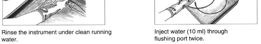
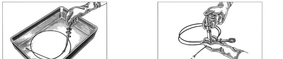
56 Using short stokes, feed the brush through the insertion tube until it emerges from the distal end of the scope. Clean off the bristles with your fingertips. Carefully pull the brush back through the channel. Clean off the bristles again. If debris remains after brushing repeat until all debris is removed. Insert the channel opening cleaning brush (MH-507) into the suction valve cylinder until approximately half of the brush head is inside the opening. Rotate the brush once and then pull it out. Wash the bristles. Repeat for the biopsy port. Flushing of Internal Channels 1. Attach the Cleaning Adaptor (MAJ-222) to the bronchoscope. 2. Attach 30cc Luer Lock syringe to the injection tube s port. Inject 100mls of detergent solution to flush the channels. (If suction is available attach suction to the MAJ-222 and suction detergent solution through the scope for 30 seconds). 3. Inject air through the scopes channels to remove the detergent solution. (Or use suction to aspirate air through the channels). 4. Remove the scope from the detergent solution and immerse in a basin of fresh water. 5. Attach 30cc Luer Lock syringe to the injection tube s port. Inject 200mls of water to flush the channels. (If suction is available attach suction to the MAJ-222 and suction water through the scope for 60 seconds). 6. Inject air through the scopes channels to remove the water. (Or use suction to aspirate air through the channels). 54
57 Terminal Cleaning / Flushing: I mmediately before storing your endoscope at the completion of your list flush channels with alcohol as follows: 1. Fill a 30ml syringe with 70% isopropyl alcohol or 70% ethyl alcohol. Using the 30 ml syringe attached to the MAJ-222 cleaning adapter, flush the scopes channels with 30 mls of alcohol. 2. Flush the scopes channels with 60 mls of air. Use a lint free cloth moistened with 70% isopropyl alcohol or 70% ethyl alcohol to thoroughly wipe the external surfaces of the bronchoscope. 55
TJF-Q180V Cleaning and Disinfection Checklist
 TJF-Q180V Cleaning and Disinfection Checklist TJF-Q180V Cleaning and Disinfection Checklist This checklist is used to evaluate and confirm if cleaning and disinfection of the TJF-Q180V has been performed
TJF-Q180V Cleaning and Disinfection Checklist
 TJF-Q180V Cleaning and Disinfection Checklist TJF-Q180V Cleaning and Disinfection Checklist This checklist is used to evaluate and confirm if cleaning and disinfection of the TJF-Q180V has been performed
INSTRUCTIONS OLYMPUS GIF TYPE 2TQ260M EVIS LUCERA GASTROINTESTINAL VIDEOSCOPE
 INSTRUCTIONS EVIS LUCERA GASTROINTESTINAL VIDEOSCOPE OLYMPUS GIF TYPE 2TQ260M Refer to the endoscope s companion manual, the OLYMPUS GIF TYPE 2TQ260M REPROCESSING MANUAL for reprocessing information. Contents
INSTRUCTIONS EVIS EXERA II DUODENOVIDEOSCOPE OLYMPUS TJF TYPE Q180V
 INSTRUCTIONS EVIS EXERA II DUODENOVIDEOSCOPE OLYMPUS TJF TYPE Q180V Refer to the endoscope s companion manual, the OLYMPUS TJF TYPE Q180V REPROCESSING MANUAL, for reprocessing information. USA: CAUTION:
Endo-Flush Order # ZUTR30004 OPERATION MANUAL. Zutron Medical, LLC W 98 th St #40-27 Lenexa, KS Phone Fax
 OPERATION MANUAL Zutron Medical, LLC 17501 W 98 th St #40-27 Lenexa, KS 66219 Phone 877-343-5873 Fax 913-967-5944 ZUT-Lab-004-30004 REV. 03312017 Table of Contents 2 Introduction 1. Intended Use 2. Labels,
The purpose of this DOPs form is to provide a universal training and assessment tool for continuity when training in manual cleaning processes.
 1 Insert company logo Formative DOPS Assessment Form Manual Cleaning of Gastrointestinal Endoscopes Hospital: Trainee s name (print): Job title: Date of assessment: Review date: Manufacturer: Equipment
Prestige Endoscopic Graspers Instructions for Use
 Prestige Endoscopic Graspers Instructions for Use DESCRIPTION The Prestige Endoscopic Graspers are designed to grasp soft tissue during endoscopic procedures. The graspers are designed to be used through
Assembly Drawing: W-311B-A01, or as applicable Parts List: W-311B-A01-1, or as applicable Special Tools: , , &
 REDQ Regulators Model 411B Barstock Design Powreactor Dome Regulator OPERATION AND MAINTENANCE Contents Scope..............................1 Installation..........................1 General Description....................1
INSTRUCTIONS. Sterilization lot number
 Single Use 3-Lumen Extraction Balloon V B-V231P-A, B-V231P-B INSTRUCTIONS USA: CAUTION: This Product Contains Natural Rubber Latex Which May Cause Allergic Reactions. Federal law restricts this device
MONT BLANC 10400X XL XLED 10401X XL XLED 10403X XL XLED
 MONT BLANC CONTR-ANGL D IMPLANTOLOGI 20:1 IMPLANTOLOGY CONTRA-ANGL 20:1 CONTRAANGULO PARA IMPLANTOLOGIA 20:1 CONTRANGOLO D IMPLANTOLOGIA 20:1 IMPLANTOLOGI WINKLSTÜCK 20:1 CONTRA-ÂNGULO PARA IMPLANTOLOGIA
Shukla Medical. TITLE: Manual Surgical Orthopedic Instruments Recommendations for Care, Cleaning, Maintenance and Sterilization
 Page 1 of 5 1. PROCESSING INSTRUCTIONS These processing instructions are intended to assist the hospital and central supply management in developing procedures for safe and effective reprocessing of both,
COMMON PRECAUTIONS Data Sheet - Be Sure To Read Before Handling Page 1 of 6
 COMMON PRECAUTIONS Page 1 of 6 These safety instructions are intended to prevent a hazardous situation and/or equipment damage. These instructions indicate the level of potential hazard by labels of "Caution",
OPERATION MANUAL. Hand Held Leak Tester Model # ZUTR-10002
 OPERATION MANUAL ZUT-Lab-003-10002 REV. B Table of Contents Page 2 Introduction 1. Intended Use 2. Labels, Symbols and Signal Words Page 3 Page 4 Page 5 Important Safety Information and Cleaning Procedure
Underwater Housing for Canon EOS M
 Underwater Housing for Canon EOS M User Manual 1 Table of Contents 1. Introduction 2. Specifications 3. Function Controls 4. Set up Instructions 5. Use & Care of Housing 6. Service 7. Warranty 1. Introduction
Alfred ECMO Circuit Priming and Storage Guide
 Alfred ECMO Circuit Priming and Storage Guide 1 March 2012 Check List Page 2. Assembly, Priming and Storage Page 3. Prepare ECMO trolley and Circuit immediately before use Page 6. Connection to Patient
Model VR6 System. Installation, Operation & Maintenance
 Model VR6 System Installation, Operation & Maintenance General: All Archer Instruments chlorination systems are carefully designed and tested for years of safe, accurate field service. All Archer Instruments
INSTRUCTIONS. Rotatable Clip Fixing Device HX-110LR HX-110QR HX-110UR. Clip HX HX Long Clip HX L.
 INSTRUCTIONS Rotatable Clip Fixing Device HX-110LR HX-110QR HX-110UR Clip HX-610-090 HX-610-135 Long Clip HX-610-090L Short Clip HX-610-090S HX-610-135S Colored Short Clip HX-610-090SC AUTOCLAVABLE Contents
PORTABLE WORK LIGHT MODEL NO: CL6FS OPERATION INSTRUCTIONS PART NO: GC0315
 PORTABLE WORK LIGHT MODEL NO: CL6FS PART NO: 4003530 OPERATION INSTRUCTIONS GC0315 INTRODUCTION Thank you for purchasing this CLARKE Worklight. Before attempting to use this product, please read this manual
Hydraulic Punch Drivers
 SERVICE MANUAL 7804SB / 7806SB Quick Draw 7704SB / 7706SB Quick Draw Flex Quick Draw Hydraulic Punch Drivers Serial Codes AHJ and YZ Read and understand all of the instructions and safety information in
Procedure 85 Attaching The Humidifier To The Oxygen Flow Meter Or Regulator. Procedure 86 Administering Oxygen Through A Nasal Cannula
 Chapter 12 Respiratory Procedures Procedure 81 Checking Capillary Refill Procedure 82 Using A Pulse Oximeter Procedure 83 Preparing Wall-Outlet Oxygen Procedure 84 Preparing The Oxygen Cylinder Procedure
Standard. Abdominal Aortic Aneurysm (AAA) Repair Trainer. Part No: 60610
 Repair Trainer. Part No: 60610") User Guide Abdominal Aortic Aneurysm (AAA) Repair Trainer Part No: 6060 Standard Part No: 065-088 Issue, June 005 04 Limbs & Things For more Vascular training products visit limbsandthings.com Limbs &
User Guide Abdominal Aortic Aneurysm (AAA) Repair Trainer Part No: 6060 Standard Part No: 065-088 Issue, June 005 04 Limbs & Things For more Vascular training products visit limbsandthings.com Limbs &
BD Cytopeia Fluidic Kit User s Guide
 BD Cytopeia Fluidic Kit User s Guide For Research Use Only 23-17618-00 9/2015 Becton, Dickinson and Company BD Biosciences 2350 Qume Drive San Jose, CA 95131 USA BD Biosciences European Customer Support
Rejuvenation Instructions
 Rejuvenation Instructions #401 Air Systems UPR This NRI covers the following: Understanding the applications and operation of flow meters. Understand the application and operation of test pressure gauges.
AMBLER SURGICAL INSTRUCTIONS FOR USE - OPHTHALMIC DUET-STYLE SCISSORS
 AMBLER SURGICAL INSTRUCTIONS FOR USE - OPHTHALMIC DUET-STYLE SCISSORS Ambler Item # 6112E Duet-style MICS Packer/Chang IOL cutter, 1 3/8", 19 gauge, straight shaft, for use with Ambler #6100T INDICATIONS
User Guide. Tripod. flowtech 75 / 100 Tripod. Part No. S S
 User Guide flowtech 75 / 100 Tripod Tripod Part No. S2051-0001 S2052-0001 EN www.sachtler.com TM Copyright 2018 All rights reserved. Original Instructions: English All rights reserved throughout the world.
Installing ASI Umbilical Delivery Systems
 Rev A 05 Nov 2015 Page 1 of 10 PURPOSE This guide provides an overview of tubing connections into an ASI wall-mounted Junction Box that has already been plumbed with a compressed air connection including
Best Practice for Calibrating LTH Conductivity Instruments
 Application Note Best Practice for Calibrating LTH Conductivity Instruments As accurate process measurement becomes an everyday requirement it is vital to be able to calibrate conductivity instruments
Instruction Manual for Configura Cushionair Portable Pump
 Instruction Manual for Configura Cushionair Portable Pump Fitted with battery powered pump, suitable for Configura Portable chairs V E R S I O N O N E M A Y 2 0 1 6 Contents Introduction 3 Set up of Cushionair
Underwater Housing for Canon G7X Mark II
 Underwater Housing for Canon G7X Mark II Product Number 6146.08 Product Registration Please register your product at ikelite.com within 15 days of purchase. Our product registration database is the best
Sterile Visual Flow Indicator
 Sterile Visual Flow Indicator Sanitary Process Connection Installation / Operation / Maintenance Manual P.O. Box 1116 Twinsburg, OH 44087 Phone: 330/405-3040 Fax: 330/405-3070 E-mail: view@ljstar.com Web
Abdominal Aortic Aneurysm (AAA) Repair Trainer User Guide
 Repair Trainer User Guide") Abdominal Aortic Aneurysm (AAA) Repair Trainer User Guide Designed and manufactured by Limbs & Things Limited, Sussex Street, St. Philips, Bristol, BS 0RA, UK. Telephone: +44 (0)7 3 0500 Fax: +44 (0)7
Abdominal Aortic Aneurysm (AAA) Repair Trainer User Guide Designed and manufactured by Limbs & Things Limited, Sussex Street, St. Philips, Bristol, BS 0RA, UK. Telephone: +44 (0)7 3 0500 Fax: +44 (0)7
Frigitronics CRYO-PLUS
 Frigitronics CRYO-PLUS OPERATING & MAINTENANCE MANUAL REF 2400 R x Only CAUTION: Federal (USA) law restricts this device to sale by or on the order of a physician. INDICATIONS FOR USE The Cryo-Plus is
Syringe, Distribution Valve and Infusion Pump Removal/Replacement ATTENTION SYRINGE REPLACEMENT
 ATTENTION SYRINGE REPLACEMENT Please read through the document completely before starting any repairs. Refer to the proper section in the service manual for complete removal and replacement procedures.
Table of Contents. Operating Instructions. Resource v.2 Conserving Regulator
 Operating Instructions Table of Contents Resource v.2 Conserving Regulator Safety Information Device Precautions Introduction Product Features Product Specifications Feature Illustrations Set Up Usage
INFUSION SYSTEM (110V) (220V) USER S MANUAL
 (220V) USER S MANUAL") INFUSION SYSTEM 20-6000-00 (110V) 20-6005-00 (220V) USER S MANUAL 8000 South Kolb Road Tucson, AZ 85756 Phone 800.528.1597 Fax 520.885.1189 www.wellsgrp.com email: sales@wellsgrp.com GENERAL DESCRIPTION
INFUSION SYSTEM 20-6000-00 (110V) 20-6005-00 (220V) USER S MANUAL 8000 South Kolb Road Tucson, AZ 85756 Phone 800.528.1597 Fax 520.885.1189 www.wellsgrp.com email: sales@wellsgrp.com GENERAL DESCRIPTION
Elcometer 138. Bresle Kit and Patches. Operating Instructions
 Elcometer 138 English Bresle Kit and Patches Operating Instructions R English The Conductivity Meter model B-173 has been tested in accordance with EU regulations governing Electro-magnetic compliance
WELLS JOHNSON HIGH VOLUME CANISTERS
 WELLS JOHNSON HIGH VOLUME CANISTERS USER MANUAL DISASSEMBLY OF HARVESTING CANISTERS Please follow the instructions provided to disassemble 5L, 3L, 2L, and 1L, 250mL and 500mL harvesting canisters. 1. Unscrew
Assembling & Installing your Pool Cleaner
 Assembling & Installing your Pool Cleaner STEP 1: Check Contents of the Box Remove the Badu Clean Supreme body and all parts from the box and check that the following components are included. Refer to
Med Aire Alternating Pressure Pump and Pad System
 User Manual Med Aire Alternating Pressure Pump and Pad System 14002E 14001E Symbols & Statements NOTE Indicates some tips or some information users should be aware of. CAUTION Indicates correct operating
Underwater Housing for Panasonic Lumix DMC-ZS60, DMC-TZ80
 Underwater Housing for Panasonic Lumix DMC-ZS60, DMC-TZ80 Product Number 6170.60 Product Registration Please register your product at ikelite.com within 15 days of purchase. Our product registration database
Instruction Manual. Alfa Laval SB Membrane Sample Valve ESE02963-EN Original manual
 Instruction Manual Alfa Laval SB Membrane Sample Valve ESE02963-EN2 2016-02 Original manual Table of contents The information herein is correct at the time of issue but may be subject to change without
Exeter Clinical and Health Research
 Exeter Clinical and Health Research Standard Operating Procedure: Centrifuge Operation SOP Number: NIHRexe/019/GEN Version Number & Date: V2 13/06/2017 Review Date: 13/06/2018 Superseded Version Number
Instructions for use Compressed air injector with water trap
 Instructions for use Compressed air injector with water trap Table of Contents Introduction 1. Description of Functions 2. Putting into Operation 3. Instructions for Cleaning and Care 3.1 Disassembling
BS ml Bottle Sampling Unit
 BS500 500ml Bottle Sampling Unit User Guide www.mpfiltri.co.uk 200.307-EN Covers Model Numbers BS500 SAFETY WARNING Hydraulic systems contain dangerous fluids at high pressures and temperatures. Installation,
Aseptic Techniques. Techniques for Sterile Compounding. Pharmacy Technician Training Systems Passassured, LLC
 Aseptic Techniques Techniques for Sterile Compounding Pharmacy Technician Training Systems Passassured, LLC Aseptic Techniques, Tech for Sterile Compounding PassAssured's Pharmacy Technician Training Program
VERTICAL AIR COMPRESSORS
 VERTICAL AIR COMPRESSORS MODEL NO: VE11C150, VE15C150, VE18C150 PART NO: 2226005, 2226000, 2226015 OPERATION & MAINTENANCE INSTRUCTIONS LS0615 INTRODUCTION Thank you for purchasing this CLARKE Vertical
INTRODUCTION TO THE SERVICE RIFLE AND MAINTENANCE
 INTRODUCTION TO THE SERVICE RIFLE AND MAINTENANCE 1 OVERVIEW DISASSEMBLY MAINTENANCE ASSEMBLY 2 TERMINAL LEARNING OBJECTIVE Given a service rifle, Common Combat Sling, and cleaning gear maintain a service
F-330 Instruction manual. Magic Glove Bio Skin Smoother High Frequency Ultrasound Galvanic
 F-330 Instruction manual Magic Glove Bio Skin Smoother High Frequency Ultrasound Galvanic Warning Never under any circumstances attempt to open or inspect the internal components or accessories of the
Elcometer 138. Bresle Kit and Patches. Operating Instructions
 Elcometer 138 English Bresle Kit and Patches Operating Instructions R English This product meets the Electromagnetic Compatibility Directive. The product is Class B, Group 1 ISM equipment according to
100L AIR COMPRESSOR MODEL NO: TIGER 16/1010 PART NO: OPERATION & MAINTENANCE INSTRUCTIONS LS01/13
 100L AIR COMPRESSOR MODEL NO: TIGER 16/1010 PART NO: 2244025 OPERATION & MAINTENANCE INSTRUCTIONS LS01/13 INTRODUCTION Thank you for purchasing this product. Before attempting to use this product, please
SCOPE BUDDY USER MANUAL ENDOSCOPE FLUSHING AID Rev D
 SCOPE BUDDY ENDOSCOPE FLUSHING AID USER MANUAL 50096-381 Rev D SCOPE BUDDY USER/SERVICE MANUAL FUJINON is a registered trademark of Fujinon Corporation MEDIVATORS is a registered trademark of Minntech
OPERATING INSTRUCTIONS
 OPERATING INSTRUCTIONS Tempe Pressure Cell June 1995 Fig. 1a 1400 Tempe Pressure Cells with 3cm cylinders and 6cm cylinders) mounted on the Tempe Cell Stand Fig. 1b Disassembled 1400 Tempe Pressure Cell
SMA1500 Instructions for Self Inspection SMA MANUAL INFLATION SMA AUTO INFLATION
 SMA1500 Instructions for Self Inspection SMA1501 - MANUAL INFLATION SMA1502 - AUTO INFLATION CONTENTS CONTENTS... i VISUAL INSPECTION CHECKLIST PRIOR USAGE... 1 RE-ARMING ACCORDING TO YOUR MODEL... 4 ROUTINE
SMA1060 INSTRUCTIONS FOR SELF INSPECTION SMA1061 MANUAL INFLATION SMA1062 AUTO INFLATION
 SMA1060 INSTRUCTIONS FOR SELF INSPECTION SMA1061 MANUAL INFLATION SMA1062 AUTO INFLATION Table 1 CONTENTS VISUAL INSPECTION CHECKLIST PRIOR USAGE... 1 Serial Number Date Purchased Quarterly visual inspection
REV A International ( ) 2013 MEDIVATORS Inc.
 2013 MEDIVATORS Inc.") User Manual FUJINON is a registered trademark of FUJIFILM Corporation MEDIVATORS is a registered trademark of MEDIVATORS Inc. OLYMPUS is a registered trademark of OLYMPUS Corporation. PENTAX is a registered
User Manual FUJINON is a registered trademark of FUJIFILM Corporation MEDIVATORS is a registered trademark of MEDIVATORS Inc. OLYMPUS is a registered trademark of OLYMPUS Corporation. PENTAX is a registered
(51) Int Cl.: A61B 1/00 ( )
 Int Cl.: A61B 1/00 ( )") (19) (11) EP 1 726 248 B1 (12) EUROPEAN PATENT SPECIFICATION (4) Date of publication and mention of the grant of the patent: 22.12. Bulletin /1 (21) Application number: 07790.4 (22) Date of filing: 1.03.0
(19) (11) EP 1 726 248 B1 (12) EUROPEAN PATENT SPECIFICATION (4) Date of publication and mention of the grant of the patent: 22.12. Bulletin /1 (21) Application number: 07790.4 (22) Date of filing: 1.03.0
MyoSure Setup Simplified
 MyoSure Setup Simplified This is designed as a quick reference guide only. This guide is not a substitute for the Operator s Manual and/or Instructions for Use (IFU). MyoSure Setup with Aquilex MyoSure
accidents which arise due to non-observance of these instructions and the safety information herein. SPECIFICATIONS
 18 GAUGE 1-1/4 INCH BRAD NAILER Model: 7611 CALIFORNIA PROPOSITION 65 WARNING: You can create dust when you cut, sand, drill or grind materials such as wood, paint, metal, concrete, cement, or other masonry.
Rev G Medivators Inc.
 User Manual MEDIVATORS and SCOPE BUDDY are registered trademark of Medivators Inc. OLYMPUS is a registered trademark of Olympus Corporation. PENTAX is a registered trademark of Hoya Corporation. FUJIFILM
PROPORTIONING VALVE. Model 150 INSTRUCTION MANUAL. March 2017 IMS Company Stafford Road
 PROPORTIONING VALVE Model 150 INSTRUCTION MANUAL March 2017 IMS Company 10373 Stafford Road Telephone: (440) 543-1615 Fax: (440) 543-1069 Email: sales@imscompany.com 1 Introduction IMS Company reserves
VAC-U DRIVE Swinging float arm for Acrobat like agility 36 Fin disk with DEEP VEE Scoop
 ACROBAT Vac-U-Drive Automatic Pool Cleaner VAC-U DRIVE Swinging float arm for Acrobat like agility 36 Fin disk with DEEP VEE Scoop Proven technology:diaphragm driven strength & quietness Unique hose design
OPERATOR S MANUAL Ar-Gone Weld Gas Analyzer
 July 2011 OPERATOR S MANUAL Ar-Gone Weld Gas Analyzer WARNING! Before operating this product, read and understand this Operator s Manual. Become familiar with the potential hazards of this unit. Contact
Maintenance and Calibration
 Maintenance and Calibration PeriFlux 6000 peripheral pressure made intelligent 44-00315-01 Disclaimer The information contained in this document is intended to provide general information only. It is not
Sample Concentrator SBH CONC/1 Instructions for use
 Sample Concentrator SBH CONC/1 Instructions for use Thank you for purchasing this piece of Barloworld Scientific equipment. To get the best performance from the equipment, and for your own safety, please
PRODUCT CATALOGUE OF
 PRODUCT CATALOGUE OF INTERVENTIONAL CARDIOLOGY AND GENERAL MEDICAL DISPOSABLES Table of Contents INFLATION DEVICE... 4 GUIDE WIRE (PTFE)... 5 MANIFOLD... 6 PTCA Y Connector... 7 INTRODUCER SHEATH (Femoral/
Mirage Vista Nasal Mask
 English 60 50 40 30 20 10 0 4 6 10 12 14 16 1 20 ENGLISH Mirage Vista Nasal Mask Rx Only The Mirage Vista Nasal Mask is an accessory to a non-continuous ventilator (respirator) intended for multipatient
Allspeeds Ltd. Royal Works, Atlas St Clayton le Moors Accrington Lancashire England BB5 5LW. Tel +44 (0)
") Allspeeds Ltd. Royal Works, Atlas St Clayton le Moors Accrington Lancashire England BB5 5LW Tel +44 (0)1254 615100 www.allspeeds.co.uk SOFT LINE CUTTER SL55 PRODUCT CODE No. 980504 INSTRUCTIONS FOR INSTALLATION,
Allspeeds Ltd. Royal Works, Atlas St Clayton le Moors Accrington Lancashire England BB5 5LW Tel +44 (0)1254 615100 www.allspeeds.co.uk SOFT LINE CUTTER SL55 PRODUCT CODE No. 980504 INSTRUCTIONS FOR INSTALLATION,
ShellPa. Standard Mechanical Cell Stretch System Model No: NNMS Serial #: User Manual
 ShellPa Standard Mechanical Cell Stretch System Model No: NNMS Serial #: User Manual To operate the system properly and safely, read the manual before using ShellPa. This system is not a medical device.
OLYMPUS Tough TG-3 and TG-4 Waterproof Housing MANUAL
 OLYMPUS Tough TG-3 and TG-4 Waterproof Housing Recsea CWOM-TG3/4 MANUAL Please read this manual before use. NTF CORPORATION UH Division http://www.seatool.net INTRODUCTION OLYMPUS Tough TG-3 and TG-4 Waterproof
24L AIR COMPRESSOR OPERATION & MAINTENANCE INSTRUCTIONS MODEL NO: RANGER 7/240 PART NO: LS0913
 24L AIR COMPRESSOR MODEL NO: RANGER 7/240 PART NO: 2242000 OPERATION & MAINTENANCE INSTRUCTIONS LS0913 INTRODUCTION Thank you for purchasing this CLARKE 24L Air Compressor. Please read this manual fully
Hydraulic Punch Drivers
 INSTRUCTION MANUAL 7804SB / 7806SB Quick Draw 7704SB / 7706SB Quick Draw Flex 7904SB / 7906SB Quick Draw 90 Quick Draw Hydraulic Punch Drivers Serial Codes AHJ, YZ, and ZA Read and understand all of the
PDY TON HYDRAULIC CRIMPING TOOL WARNING
 OPERATORS ORS GUIDE PDY-1220 12 TON HYDRAULIC CRIMPING TOOL All information found in this guide must be read and understood before use or testing of this tool. Failure to read and understand these warnings
12V AIR STATION ALL-IN-ONE
 [ACT 027] Manual E 6/9/05 10:18 PM Page 3 Multi use 12V AIR STATION ALL-IN-ONE OWNER S MANUAL MODEL NO: C71A-54 KEEP THE ORIGINAL BOX, PACKAGING AND RECEIPT. BEFORE OPERATING THIS UNIT, READ THE MANUAL
PRESSURE TEST PUMP OPERATING & MAINTENANCE INSTRUCTIONS. Model No: PTP100. Part No: GC01/09
 PRESSURE TEST PUMP Model No: PTP00 Part No: 06020 OPERATING & MAINTENANCE INSTRUCTIONS GC0/09 INTRODUCTION Thank you for purchasing this CLARKE Pressure Testing Pump. Before attempting to use the product,
AIR COMPRESSOR. Failure to follow all instructions as listed below may result in electrical shock, fire, and/or serious personal injury.
 2 GALLON AIR COMPRESSOR Model: 7517 DO NOT RETURN TO STORE. Please CALL 800-348-5004 for parts and service. CALIFORNIA PROPOSITION 65 WARNING: You can create dust when you cut, sand, drill or grind materials
FMA Small Animal - Rodent
 MicroProbes for Life Science FMA Small Animal - Rodent User Instructions Version: August, 2015 18247-D Flower Hill Way Gaithersburg, MD 20879 Phone: +1 301 330-9788 Fax: +1 301 330-9667 w w w.microprobes.com
Competency Record for Sonic Cleaning
 Competency Record for Sonic Cleaning Name: Competency Achieved: (Date) Evaluator: Learner: Comments: Background information on sonic testing ST 79; 2009A section 7.5.3.3 states this on weekly testing Mechanical
INDUSTRIAL - SOLVENT PARTS CLEANER
 INDUSTRIAL - SOLVENT PARTS CLEANER OPERATION & INSTRUCTION MANUAL I. Introduction A. Manufacturer s Statement CM400 This manual will provide you with important information about the Solvent Parts Cleaners
Operation and Maintenance Manual for GENTEC Model 881VR Continuous/Intermittent Digital Suction Regulators
 Operation and Maintenance Manual for GENTEC Model 881VR Continuous/Intermittent Digital Suction Regulators Genstar Technologies Co., Inc. 4525 Edison Avenue Chino, CA 91710 USA TEL 909-0-272 FAX 909-0-485
CUT OFF TOOL MODEL: CAT113
 CUT OFF TOOL MODEL: CAT113 Part No: 3120135 ASSEMBLY & INSTRUCTION MANUAL LS0309 INTRODUCTION Thank you for purchasing this CLARKE product Before attempting to use the product, it is essential that you
Service and Repair Manual
 II stage R2 Ice/ Special, II stage R 1 Pro DOWNSTREAM 2 nd STAGE REGULATOR Service and Repair Manual Introduction Safety Precautions...4 General Procedures, Maintenance Schedules...5 Initial Inspection
AutoChanger Installation & User Guide Issue 2
 1 INDEX Page 1. Introduction... 3 2. AutoChanger Components Guide 4 3. Installation. 5-11 a) Installation Guidelines.. 5 b) Installation Retrofit... 6-11 c) Installation New... 11 4. AutoChanger User Guide
OPERATION MANUAL Please read this Operation Manual carefully before use, and file for future reference.
 English Lubrication Free Air Turbine Handpiece with Water Spray OPERATION MANUAL Please read this Operation Manual carefully before use, and file for future reference. OM-T0286E 001 Thank you for purchasing
DIAGNOSTIC CARDIOLOGY
 DIAGNOSTIC CARDIOLOGY For Your Procedural Needs Manufactured to the Highest Standards, Customised to Your Specific Needs MEDLINE PROCEDURE PACKS The items contained within this brochure are perfect for
BioAerosol Nebulizing Generator. Operation and Maintenance User Manual
 BioAerosol Nebulizing Generator Operation and Maintenance User Manual INTRODUCTION The BANG or BioAerosol Nebulizing Generator is a unique nebulizer for the generation of aqueous aerosols at a low air
AIR STAPLER. MODEL: CSG3KC Part No OPERATING & MAINTENANCE INSTRUCTIONS
 AIR STAPLER MODEL: CSG3KC Part No. 3110380 0506 OPERATING & MAINTENANCE INSTRUCTIONS SPECIFICATIONS Min. Hose Size (ID)... 6mm (1/4 ) Air Inlet Connector... 10mm Quick Fit Ave. Air Consumption... 0.4 cfm
Pressure Regulator. Instructions for Use
 Pressure Regulator Instructions for Use 702-0083.9 December 2017 1. Symbols Warning! Caution! Indicates a potentially hazardous situation which, if not avoided, could result in injury to the patient, the
The NAMIC Dream Kit. Single Operator Control. Reduce Contrast Waste. Less Force to Inject. Compensator * Manifold. How the Compensator Manifold Works:
 Dream Kit The NAMIC Dream Kit Single Operator Control. Reduce Contrast Waste. Less Force to Inject. For more than 40 years, NAMIC * Fluid Management products have been providing cardiologists, technicians
G7S Hand Pump Owner s Manual
 G7S Hand Pump Owner s Manual Copyright Air Venturi 2018 Version 4-18 Specifications 24.80 inches long closed 43.31 inches long extended 4500 psi/310 bar max pressure Features Integral manometer (pressure
P5513. Users Manual. Pneumatic Comparison Test Pump. Test Equipment Depot Washington Street Melrose, MA TestEquipmentDepot.
 Test Equipment Depot - 800.517.8431-99 Washington Street Melrose, MA 02176 TestEquipmentDepot.com P5513 Pneumatic Comparison Test Pump Users Manual PN 3963372 November 2010 2010 Fluke Corporation. All
VERTICAL AIR COMPRESSORS
 VERTICAL AIR COMPRESSORS MODEL NO: VE15C150, VE18C150, VE25C150 PART NO: 2226010, 2226020, 2226025 OPERATION & MAINTENANCE INSTRUCTIONS LS0715 INTRODUCTION Thank you for purchasing this CLARKE Vertical
accidents which arise due to non-observance of these instructions and the safety information herein. SPECIFICATIONS
 18 GAUGE 2 INCH BRAD NAILER Model: 7555 CALIFORNIA PROPOSITION 65 WARNING: You can create dust when you cut, sand, drill or grind materials such as wood, paint, metal, concrete, cement, or other masonry.
Operating Instructions for BAIR22-6 AIR-POWERED CRIMPING TOOL
 Operating Instructions for BAIR22-6 AIR-POWERED CRIMPING TOOL Read and understand all of the instructions and safety information in this manual before operating or servicing this tool. Table of Contents
24L OIL FREE AIR COMPRESSOR MODEL NO: TIGER 7/250 PART NO: OPERATION & MAINTENANCE INSTRUCTIONS LS10/13
 24L OIL FREE AIR COMPRESSOR MODEL NO: TIGER 7/250 PART NO: 2244030 OPERATION & MAINTENANCE INSTRUCTIONS LS10/13 INTRODUCTION Thank you for purchasing this product. Before attempting to use this product,
Welcome to the Specialized Medical Services Respiratory training webinar series!
 Welcome to the Specialized Medical Services Respiratory training webinar series! SMS is your Long Term Care (LTC) facility single source for oxygen, medical equipment, respiratory care services and supplies
Read this first. Zetasizer nano series Self installation and Quick start guide MRK825-02
 ! Read this first Zetasizer nano series Self installation and Quick start guide I N S T R U M E N T S MRK825-02 Zetasizer Nano series Self installation and Quick start guide MAN0383 Issue 1.1 July 2007
24L AIR COMPRESSOR MODEL NO: TIGER 11/250 PART NO: OPERATION & MAINTENANCE INSTRUCTIONS LS01/13
 24L AIR COMPRESSOR MODEL NO: TIGER 11/250 PART NO: 2244010 OPERATION & MAINTENANCE INSTRUCTIONS LS01/13 INTRODUCTION Thank you for purchasing this product. Before attempting to use this product, please
Contents: 1. Introduction
 Camera Underwater Housing G11 (Canon) User Manual Contents: 1. Introduction 2. Specifications 3. Function Controls 4. Set up Instructions 5. Use & Care of Housing 6. Service 7. Warranty 1. Introduction
CRANE WITH WINCH USE AND MAINTENANCE MANUAL. Code Rev. Release MD /03
 CRANE WITH WINCH Code Rev. Release MD.0.097 0 06/03 USE AND MAINTENANCE MANUAL CONTENTS 1 FOREWORD page 3 1.1 Description of the crane with winch page 3 2 USE OF THE CRANE WITH WINCH page 3 2.1 General
REL-510H WARNING NOTICE 12 TON SINGLE ACTING REMOTE HYDRAULIC CRIMPING HEAD
 OPERATORS ORS GUIDE REL-510H 12 TON SINGLE ACTING REMOTE HYDRAULIC CRIMPING HEAD Compatible with U style and RELIABLE R12 shell type 12 ton compression dies. RELIABLE EQUIPMENT & SERVICE CO., INC. 92 Steamwhistle