Baron Oxygen STC Installation Instructions (Front Baggage Installation) GAMI/Tornado Alley Turbo 2009
|
|
|
- Daniel Wilfrid Marshall
- 6 years ago
- Views:
Transcription
1 Baron Oxygen STC Installation Instructions (Front Baggage Installation) GAMI/Tornado Alley Turbo 2009
2 Revision Page Slide Revision Slide Revision Slide Revision Slide Revision x.i NC 3.5 NC 3.20 NC 6.6 F x.ii D 3.6 E 3.21 NC 6.7 F 1.1 NC 3.7 F 3.22 F 6.8 F 1.2 NC 3.8 NC 3.23 F 6.9 F 1.3 F 3.9 F 4.1 E 6.10 NC 1.4 F 3.10 NC 4.2 NC 6.11 F 1.5 F 3.11 F 5.1 A 7.1 D 2.1 E 3.12 NC 5.2 E 7.2 D 2.2 F 3.13 F 5.3 E 7.3 D 2.3 F 3.14 NC 5.4 F 2.4 NC 3.15 F 6.1 NC 3.1 NC 3.16 NC 6.2 NC 3.2 NC 3.17 F 6.3 NC 3.3 NC 3.18 F 6.4 NC 3.4 F 3.19 F 6.5 NC
3 Table Of Contents Section Description Slide # Introduction x.i FS Fill Station Installation 1.1 OB Oxygen Bottle Installation 2.1 IO Interior Oxygen Installation 3.1 FI Finalizing Bottle Installation 4.1 CI Oxygen Bottle Cover Installation 5.1 R Reference 6.1 W Weight and Balance 7.1 Rev NC x.i
4 Installation Instruction Notes All item ## listed in slides refer to item ## in parts list. All fuselage station references are for Baron 58 series aircraft. Use appropriate station references for installation of O2 system in Baron 55 series. Refer to Hawker/Beechcraft Baron AMM for any procedures not specifically covered in these instructions. Some airplanes may have previously installed equipment that may interfere with the installation of this STC. It is the responsibility of the installer to determine alternate procedures. Electrical Requirements: On a 24V system the Remote Control Valve (RCV) requires about 0.43 amp to activate and 0.22 amp to keep the valve on. Rev D x.ii
5 FS-1 Fill Station Installation 1. In the forward baggage compartment, remove all insulation and sound proofing from the battery compartment rearward. 2. Remove screws for panel rear of battery compartment and take out of aircraft. P1 Rev NC 1.1


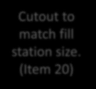
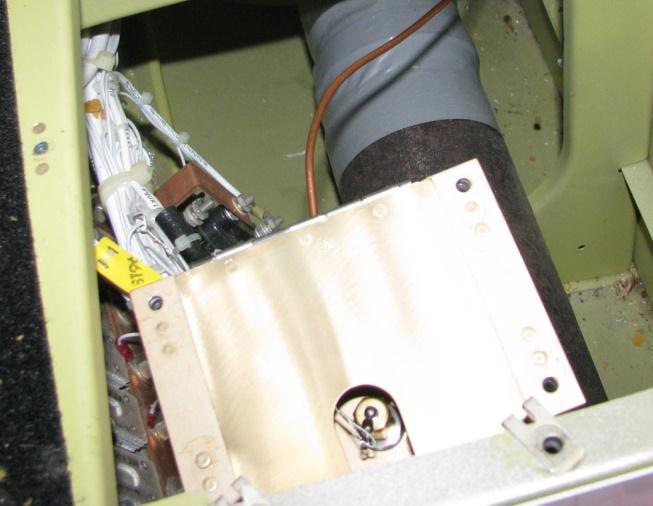
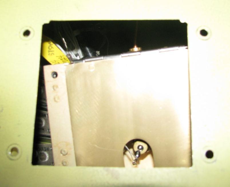
6 FS-2 Fill Station Installation (cont) 55 Cutout to match fill station size. (Item 20) P3 P2 P4 Rev NC 1.2
 as shown in red (next page). NOTE: Adel clamps (item 19) shown with blue circles (station 27.")
7 FS-3 Fill Station Installation (cont) 3. Cut hole out of panel (3.3 x 3.4 ) as shown on slide Hole is located 1.5 from each edge from front and right side of panel. 4. Match drill 4 screw holes from item 20 to floor panel. 5. Route high pressure copper tubing (item 14) as shown in red (next page). NOTE: Adel clamps (item 19) shown with blue circles (station 27.00), grommet shown with purple circle. Ground Here Rev F P5 P6 1.3
8 FS-4 Fill Station Installation (cont) 6. Attach Adel clamp (item 19) to former, at station 27.00, where copper tubing passes near existing #10 hole. Attach Adel clamp with AN3-3A bolt, NAS1149F0332P washer, and MS locknut. 7. Install grommet (item 23) where copper tubing comes through floor panel (just aft of station 27.00). Enlarge hole for grommet to.312/.375 if required for ease of installation. P7 Rev F 1.4
9 FS-5 Fill Station Installation (cont) 8. When installing high pressure copper tubing, you must: 1. Install ferrules (supplied with B-nuts on O2 fittings) 2. Hand tighten nut 3. Add ¼ turn to nut to seat brass and copper. Reference slide 6.5 Rev F 1.5

10 OB-1 Oxygen Bottle Installation 1. If not already removed, remove all insulation from battery compartment rearward. 2. Relocate alternator regulator using already present nutplates from installations in older B58 models, cut insulation where needed being careful not to scratch the paint underneath the insulation. 3. Install item 56 at previous alternator regulator location. 4. Remove heater duct, then run wiring for alternator regulator through holes to new location (shown as red dashed line in P8). See Step #4 See Step #2 Rev E P8 2.1

11 OB-1 Oxygen Bottle Installation (cont) BRACKET MS20470AD4 RIVET TAPPED BUSHING SCREW P9 BASE CHAFE PROTECTION BUSHING SHEATH Rev F 2.2


12 OB-2 Oxygen Bottle Installation (cont) 5. Install brackets (item 58 or 59) using provided rivets (MS20470AD4-4). Brackets should be.25 from rear bulkhead and adjacent to top skin of compartment. This will place the oxygen bottle center of gravity at station Reference P9 on previous slide. In P11, item 58 is used for the 115 cu. in. bottle, but item 59 may be used when installing the 77 cu. in. bottle. Note: Ensure all predrilled holes in bracket have proper alignment and edge distance to factory formers. See Step #5 P10 P11 Rev F 2.3
13 OB-3 Oxygen Bottle Installation (cont) 6. Reinstall heater duct removed in step Connect high pressure tubing to fill port box. See slide 1.4 for procedure. Rev NC 2.4

14 IO-1 Interior Oxygen Installation 1. Remove pilot and copilot s interior, headliner, kick panels and seats, in accordance with Hawker/Beechcraft Baron AMM. Picture: From Rear Cargo Door Rev NC The next 4 slides give an overview of the oxygen tubing installation. Subsequent slides then describe in greater detail each tubes installation. P12 3.1

15 IO-2 Torque all threaded connections to 130 inch lbs Sta Forward baggage compartment aft wall Existing hole in wall FWD AFT Rev NC 3.2

16 IO-2 Spar front AFT 32 Forward baggage compartment aft wall Adel clamps and attaching hardware 16, 17, 18, and 33 at four places 32 Co-pilot side wall Rev NC 3.3

17 IO-2 Torque all threaded connections to 130 inch lbs. 6 4 Adel clamp and attaching hardware 17, 18, 50, 52 and 33, see P Structure that the tubing runs thru lightening holes Rev F 3.4

18 IO-2 Headliner Left emergency exit window aft structure FWD AFT Torque all threaded connections to 130 inch lbs Rev NC 3.5

19 IO-2 Interior Oxygen Installation (cont) 2. Install formed aluminum tubes starting with item Use proper mechanical technique when installing tubes, tightening nuts and fittings to 130 in-lbs. 4. Minor hand forming to adjust tubing may be necessary, perform as required. Chafe protection must be used when aluminum tubing is run through formers. 4 Picture: Under Emergency Exit Window (L/H) 6 P13 Rev E 3.6
 Install Adel clamp on center of frame flange in location that allows best routing of O2 tube without binding or interference with existing systems.")
20 IO-2 Interior Oxygen Installation (cont) NOTE: Picture P14 is a picture of the Adel clamp and standoff used for item 5. Picture: Under Emergency Exit Window (L/H) Install Adel clamp on center of frame flange in location that allows best routing of O2 tube without binding or interference with existing systems. Clearance size hole for #10 fastener is.193/.200 inch diameter (#10 drill) & P14 Rev F 3.7


 5 P16 7 Picture: L/H")
21 IO-2 Interior Oxygen Installation (cont) 5. From step #2, continue installing aluminum tubes toward the front, in order as shown. Red lines parallel to tubing to help show setup. Use existing holes on mounting brackets forward of station to install 3 Adel clamps. 4 Picture: Below Emergency Exit Window (L/H) 5 P16 7 Picture: L/H side of Pilot s Seat 5 P17 Picture: Under P15 Pilot s Seat Rev NC 5 3.8

. At the forward end of P19, station 39.")
22 IO-2 Interior Oxygen Installation (cont) 6. P18 shows the aluminum tube crossing from left to right, in front of station 82.96, add Adel clamps (shown in blue circles below) to existing holes on mounting brackets. Add Adel clamp to station as seen in P19, the hole will need to be drilled (.193/.200 diameter). At the forward end of P19, station 39.00, there will be a bulkhead fitting. (not shown) Picture: Under Co- Pilot s Seat Picture: Co-Pilot s Seat P18 12 P19 8 Rev F 3.9
 NOTE: Here are pictures of the")


23 IO-2 Interior Oxygen Installation (cont) NOTE: Here are pictures of the Adel clamp on the front spar Picture: Under Pilot s Seat Picture: Under Co- Pilot s Seat 7 P P22 Picture: Front Door Note: Adel clamp 12 P21 Rev NC 3.10

24 IO-3 Interior Oxygen Installation (cont) Rev F 7. Add Adel clamp at existing Adel clamp location on former at station , then route aluminum tube (item 13) through it. The holes for the end of the tube are existing, use these to add fittings. 8. There are two bulkhead fittings in P23, shown in yellow circles. Both of these fittings use 90 fitting on one end and a straight fitting on the other, as shown in P23. Reference slide Picture: Rear of Emergency Exit(L/H) P

25 IO-3 Interior Oxygen Installation (cont) NOTE: Picture P24 shows the bulkhead fittings. Ensure proper build up when installing, leakage may occur if not properly installed. Picture: Rear of Emergency Exit(L/H) P24 Rev NC 3.12

26 IO-4 Interior Oxygen Installation (cont) 9. After aluminum tubing is installed, flexible tubing installation can be started. The routing is in a closed loop setup, to allow each user to receive equal amounts of oxygen. 10. The installation tries to make use of the maximum amount of existing holes in the airframe structure, See Note #10 P25 but the flexible tubing crosses an airframe brace twice that will need reinforcements (item 54). Reference slide 3.15 Rev F 3.13


27 IO-4 Interior Oxygen Installation (cont) NOTE: Make sure when connecting low pressure tubing to fittings that the tube is completely pushed in, then tugged to make sure the tubing is seated and will not leak. NOTE: Ensure all flexible tubing is routed and protected from any possible chafe or compression that may cause failure. Note: Low Pressure T P27 P26 Rev NC 3.14
. Mix and apply adhesive in accordance with manufacturer s instructions. 54 1 P28 Rev F 3.")
28 IO-5 Interior Oxygen Installation (cont) Picture: Above Passenger Seats Behind Pilot Seats Install flex tube protectors (Item 54) using two part epoxy adhesive supplied in kit (Item 74). Mix and apply adhesive in accordance with manufacturer s instructions P28 Rev F 3.15

29 IO-6 Interior Oxygen Installation (cont) Picture P29 shows the transition from preformed aluminum tubing to the flexible tubing. Reference P29 when connecting flexible tubing to aluminum tubes to ensure proper connection. Picture: Above and Behind Emergency Exit Window (L/H) P29 Rev NC 3.16


30 IO-7 Interior Oxygen Installation (cont) 11. With the headliner removed, install items 44 and 45 which are the oxygen ports in the cabin. Drill or machine 7/16 inch diameter holes in headliner to accommodate the oxygen ports. In picture P30, the front of the aircraft is toward the right. Reference installation figure (slide 6.6) for installation of oxygen ports. 45 P31 P30 Rev F 3.17


31 IO-7 Interior Oxygen Installation (cont) P32 Item 44 Item 44 P Install items 44 and 45 as shown. Items 44 and 45 need a 90 fitting or a straight fitting as seen in the pictures, items 30 and 31. Dimensions are on the next page. P34 Rev F 3.18
 1 from edge (both sides) P35")
 5 from outboard hole 1 from")
32 IO-7 Interior Oxygen Installation (cont) 2 from edge (both sides) 1 from edge (both sides) P35 Note: Flexible Tubing Clamps (Item 72) with tie-wraps (Item 73) 5 from outboard hole 1 from edge P36 Rev F 3.19
 P37 P38 NOTE: When reinstalling")


33 IO-8 Interior Oxygen Installation (cont) P37 P38 NOTE: When reinstalling headliner, ensure proper connection of flexible tubing and oxygen ports, as seen in P37 and P39. This may require the help of more than one installer. P39 Rev NC 3.20
 P40 Rev")
34 IO-8 Interior Oxygen Installation (cont) P40 Rev NC 3.21
 or in lower central portion of instrument panel (see Slide 6.8).")
35 IO-9 Interior Oxygen Installation (cont) 1. The gauge installation should be installed in the co-pilot s side of the instrument panel (shown in P41) or in lower central portion of instrument panel (see Slide 6.8). Locate the gauge and switch such that they do not interfere with existing equipment on or behind the panel. The switch may be located to the right or left of the gauge based upon clearance with existing equipment and/or personal preference. 2. Install item 48 over oxygen switch, as shown in P41. P41 Rev F 3.22
36 IO-9 Interior Oxygen Installation (cont) 3. Route electrical wires from baggage compartment to cabin thru existing opening below the right engine alternator regulator, with existing wiring from voltage regulator. 4. Attach ground wire using existing hole on former by first removing paint in the area around the hole, reference slide Splice power in from aircraft to 28/14V IN (letter A on ) aft of wall as shown on Run 5 (item 43) wire from Item 65 to right hand side of instrument panel to attach to oxygen switch with existing wire bundle. 7. Instrument lighting positive and ground (letter B and C, respectively, on ) should be connected to copilot s subpanel lighting wiring. NOTE: Ensure Item 65 is behind circuit panel and run 5 wire to switch next to O2 pressure gage. 8. Reference and for wiring diagram.(in Reference section) 9. Install circuit breaker placards (Item 68) over circuit breakers. Rev F 3.23
37 FI-1 Oxygen Bottle Installation 1. Lift oxygen bottle with attached RCR/RCV valve (item 60 or 61 depending on 115 or 77 cu. in. bottle) to bottom of brackets then clamp straps finger tight and repeat for second set of straps as shown in pictures on next page. NOTE: If installing a 77 cu. in. bottle (item 61), ensure item 63 is installed between bottle and straps before tightening. 2. Tighten strap locknut to 60 in-lbs plus the run on value for the nut being installed. Rev E 4.1

 installation, while P43 shows a 77 cu.")
38 FI-1 Oxygen Bottle Installation NOTE: Ensure bottle does not touch heater tube insulation, as this may cause chafing. P42 3. Final oxygen bottle installation should look like either P42 or P43. P42 shows a 115 cu. in. bottle (item 60) installation, while P43 shows a 77 cu. in. bottle (item 61) installation. P43 Rev NC 4.2
 to bottle cover as shown in P44. Item 66 or 67 (depending on bottle size) P44 Rev A 5.1")
39 CI-1 Oxygen Bottle Cover Installation 1. Install item 2, add cover to bottle using existing floating nutplate bracket. 2. Thread strap behind bottle then attach cover to nutplates with screws. 3. Install item 62 on exposed bolts from the bottle strap. 4. Attach item 66 or 67 (depending on bottle size) to bottle cover as shown in P44. Item 66 or 67 (depending on bottle size) P44 Rev A 5.1
40 FI-1 Bottle Charge & Leak Check SYSTEM LEAK CHECK (TROUBLESHOOTING) Charge O2 system as detailed on next page. Unplug all masks and/or cannulas from oxygen ports. Turn Master Switch ON. Turn Oxygen Switch ON. Check Oxygen Pressure Gage for pressure reading. A pressure of approximately 1,800 psi (at 70 F) should be indicated on the gage when the oxygen cylinder is full. (Cylinder pressure will vary considerably with radical temperature changes.) The gage near the fill port should indicate nearly the same pressure as the instrument panel mounted gage. Check the complete system for leaks by monitoring the pressure for one hour. If there is less than a 100 psi drop in pressure in one hour the system is considered acceptable. Shut oxygen OFF until inflight use is required. Turn Master Switch OFF. Rev E 5.2
41 FI-2 Bottle Charge & Leak Check When filling the oxygen system, use only 99.99% pure oxygen to be sure that it does not contain moisture which can cause the oxygen valve to freeze. Do not service the oxygen system at the same time and in the same area that the fuel system is being serviced. To service the oxygen system, use the following procedures for initial charging as well as subsequent charging: Gain access to the filler port for the oxygen system (see Descriptive Data for filler port location). Check oxygen cylinder pressure gage. If the cylinder is completely empty or open, check to make sure it has not been internally contaminated with any combustible materials such as oils, fluids, or gases, before charging. If you are unsure, empty cylinder must be removed, inspected, and cleaned before charging. Check the hydrostatic test date of the cylinder. Oxygen bottles installed in accordance with Engine Technologies, Inc. STC SA10960SC are Kevlar wrapped aluminum specifically designed for aviation use. They must be hydrostatically tested every 5 years and must be retired from service after 15 years. If the periodic retest date is past, do not return the cylinder to service until the test has been accomplished. Remove the cap from the filler valve and attach the recharging outlet. Slowly open the valve of the cylinder on the oxygen filling manifold system having the lowest pressure and allow the pressure to equalize. Close the cylinder valve on the manifold system and slowly open the valve of the cylinder having the next highest pressure. Continue this procedure until the cylinder has been charged to 1850 ± 50 psi at an ambient temperature of 70ºF. This pressure may be increased an additional 3.5 psi for each degree of increase in ambient temperature. Similarly, for each degree of drop in ambient temperature, reduce the cylinder pressure 3.5 psi. Close all valves on the manifold system. Remove the recharging outlet, and replace the filler valve cap. Let the cylinder stabilize for a period of at least 1 hour, and then recheck the pressure. Make any necessary adjustments in the pressure. Reinstall components removed to gain access to the filler valve. Rev E 5.3
42 FP-1 Final Paperwork Insert Airplane Flight Manual Supplement (Item 70) in airplane flight manual. Perform Aircraft Weight and Balance change (see slides 7.1 thru 7.3). Keep these instructions and Instructions for Continued Airworthiness (Item 71) with aircraft maintenance logs for future reference. Rev F 5.4
43 R-1 Reference Rev NC 6.1
44 R-2 Reference (cont) Rev NC 6.2
45 R-3 Reference (cont) Rev NC 6.3
46 R-4 Reference (cont) Rev NC 6.4
47 R-5 Reference (cont) Rev NC 6.5
48 R-6 Reference (cont) Rev F 6.6
49 R-7 Reference (cont) Rev F 6.7
50 R-8 Reference (cont) Rev F 6.8
51 R-9 Reference (cont) Rev F 6.9
52 10 Reference (cont) Rev NC 6.10
53 R-11 Reference (cont) 55, 58 Baron O2 Parts List Rev F Item # Part Name Part Number Qty Item # Part Name Part Number Qty 1 Tube Protector O2 Gage Electrical Connector ETI-B-5006P6-B 1 2 Bottle Cover Assembly O2 Gage Switch ETI-B-5006P6-D 1 3 RCR Electrical Connector ETI-B-5006P6-C 1 40 Screw MS Aluminum Oxygen Tube Assembly Butt Splice AP Aluminum Oxygen Tube Assembly Ring Terminal (#6) AP Aluminum Oxygen Tube Assembly Electrical Wire, 5 ft WM22759\ Aluminum Oxygen Tube Assembly User Block Aluminum Oxygen Tube Assembly User Block Port Aluminum Oxygen Tube Assembly Washer NAS1149C0732R 6 10 Aluminum Oxygen Tube Assembly Bolt AN3-11A 2 11 Aluminum Oxygen Tube Assembly Oxygen Switch Placard Aluminum Oxygen Tube Assembly Aluminum Oxygen Tube Assembly Screw AN525-10R High Pressure Copper Tubing, 4 ft Ring Terminal (#10) AP /2" Spacer Bolt AN3-3A 8 53 Flowmeter and Cannula Washer NAS1149F0332P Flex Tube Protector Nut MS Filler Port Placard Adel Clamp MS21919WDG Alternator Regulator Patch Filler Box w/gage Secure Baggage Placard Screw AN R Bracket Assembly Cu Ft Bottle ** Bracket Assembly - 77 Cu Ft Bottle * 23 Grommet MS Cu Ft O2 Bottle ** 24 Bulkhead Fitting AN833-4D Cu Ft O2 Bottle * 25 B-Nut AN924-4D 3 62 Bolt Cover Washer NAS1149F0763P to 77 Bottle Adapter * 27 AN-to-pipe thread Fitting AN816-4D (alt. 2 AS5194D0402) 64 RCR Valve Brass Union 3300x Dual Isolated Power System Low Pressure Tee 00-HDW Cu Ft Bottle Placard * 30 Low Pressure Straight Fitting 00-HDW Cu Ft Bottle Placard ** 31 Low Pressure 90 Fitting 00-HDW Circuit Breaker Placard AN Aluminum Union AS5174D Baron O2 Installation Instructions Adel Clamp MS21919WDG Airplane Flight Manual Supplement Low Pressure O2 Tubing, 15, ft 00-HDW Instructions for Continued Airworthiness Grommet MS Flexible Tubing Clamp 7582K Circuit Breaker, 2 Amp Tiewrap TY5242M O2 Electric Gage 00BLT Extra Thick Quick Setting Epoxy 7538A15 1 Note: Quantities with single asterisk (*) included in kit for 77 Cu Ft Bottle Quantities with double asterisk (**) are included in kit for 115 Cu Ft Bottle 6.11
54 W-1 Weight and Balance Information Weight and balance change for 115 cubic foot O2 bottle mounted in fwd baggage compartment Baron 58 series Items Added Weight (lbs) Arm (in) Moment O2 valve/regulator pl O2 ports pl O2 port O2 fill port & gage O2 tubing - 25 ft O2 hard lines Pressure gage & switch O2 bottle support cu ft O2 bottle (full) Total Rev D 7.1
55 W-2 Weight and Balance Information Weight and balance change for 77 cubic foot O2 bottle mounted in fwd baggage compartment Baron 58 series Items Added Weight (lbs) Arm (in) Moment O2 valve/regulator pl O2 ports pl O2 port O2 fill port & gage O2 tubing - 25 ft O2 hard lines Pressure gage & switch O2 bottle support cu ft O2 bottle (full) Total Rev D 7.2
56 W-3 Weight and Balance Information Weight and balance change for 115 cubic foot O2 bottle mounted in fwd baggage compartment Baron 55 series Items Added Weight (lbs) Arm (in) Moment O2 valve/regulator pl O2 ports pl O2 port O2 fill port & gage O2 tubing - 25 ft O2 hard lines Pressure gage & switch O2 bottle support cu ft O2 bottle (full) Total Rev D 7.3
Pressure Dump Valve Service Kit for Series 3000 Units
 Instruction Sheet Pressure Dump Valve Service Kit for Series 000 Units. Overview The Nordson pressure dump valve is used to relieve hydraulic pressure instantly in Series 00, 400, 500, and 700 applicator
Installation Operating Instructions for Simple Duplex Manual Manifolds PX-TSD Series
 Introduction Powerex manifolds are cleaned, tested and prepared for the indicated gas service and are built in accordance with the Compressed Gas Association guidelines. The manifold consists of a regulator
FOR INSTALLING CO 2 BLENDER KIT (P/N IN BEER SYSTEM
 IMI CORNELIUS INC One Cornelius Place Anoka, MN 55303-623 Telephone (800) 238-3600 Facsimile (612) 22-326 INSTALLATION INSTRUCTIONS FOR INSTALLING CO 2 BLENDER KIT (P/N 111612000 IN BEER SYSTEM SECONDARY
INSTALLATION INSTRUCTIONS FOR EXHAUST CUFF MODIFICATION
 INSTALLATION INSTRUCTIONS FOR EXHAUST CUFF MODIFICATION Document # PCA1001-22 Revision LTR: A Date: 07/06/09 1 Notes: 1. The cuff must be installed onto the aircraft prior to painting. Once installed the
PARAVION TECHNOLOGY, INC AIRWAY AVENUE FT. COLLINS, COLORADO 80524
 PARAVION TECHNOLOGY, INC. 2001 AIRWAY AVENUE FT. COLLINS, COLORADO 80524 INSTRUCTIONS FOR CONTINUED AIRWORTHINESS 407LS-100 INSTALLATION BELL 407 HELICOPTERS Cover THIS PAGE INTENTIONALLY LEFT BLANK Page
BASIC AIRCRAFT STRUCTURES
 Slide 1 BASIC AIRCRAFT STRUCTURES The basic aircraft structure serves multiple purposes. Such as aircraft aerodynamics; which indicates how smooth the aircraft flies thru the air (The Skelton of the aircraft
Pressure Dump Valve Service Kit for Series 2300 Units
 Instruction Sheet Pressure Dump Valve Service Kit for Series 00 Units. Overview The Nordson pressure dump valve is used to relieve hydraulic pressure instantly in Series 00 applicator tanks when the unit
INSTALLATION INSTRUCTIONS. CVS 67CFR Pressure Reducing Instrument Supply Regulator INTRODUCTION
 INSTALLATION INSTRUCTIONS CVS 67CFR Pressure Reducing Instrument Supply Regulator INTRODUCTION The CVS Controls 67CFR Filter regulator is a pressure reducing supply regulator typically used for pneumatic
SECTION 23iS/U: SIDE SKINS
 SECTION 23iS/U: SIDE SKINS F-1203G-R BULKHEAD SIDE CHANNEL F-01248-R-1 ARM REST F-01205D SEAT BACK ADJUSTMENT GUIDE, 4 PLACES F-01205B-1 ROLL BAR ATTACH PLATE, F-01248B-1 FUSELAGE PIN LATCH, F-01204J BULKHEAD
Ice Protection System
 Cirrus Design Section 9 Pilot s Operating Handbook and FAA Approved Airplane Flight Manual Supplement for Ice Protection System When the Ice Protection System is installed on the Cirrus Design, this POH
Assembly Drawing: W-311B-A01, or as applicable Parts List: W-311B-A01-1, or as applicable Special Tools: , , &
 REDQ Regulators Model 411B Barstock Design Powreactor Dome Regulator OPERATION AND MAINTENANCE Contents Scope..............................1 Installation..........................1 General Description....................1
DESCRIPTION AND OPERATION OXYGEN SYSTEM OXYGEN SYSTEM
 2.20. 2.20.1 EMERGENCY SUPPLEMENTARY OXYGEN WARNING Positively NO SMOKING while oxygen is being used by anyone in the airplane. Keep the entire system free from oil and grease (to avoid the danger of spontaneous
Poppetted Coaxial Drop Tube Assembly for use with Auto Limiter II. Installation Instructions
 Poppetted Coaxial Drop Tube Assembly for use with Auto Limiter II Installation Instructions Franklin Fueling Systems 3760 Marsh Rd. Madison, WI 53718 USA Tel: +1 608 838 8786 800 225 9787 Fax: +1 608 838
! CAUTION! ! WARNING! General Information
 Great Plains Mfg., Inc. Installation Instructions Used with: 2SF24, 24-Foot Two-Section Drill General Information Two-Section, Hydraulic Folding Marker 2SF30, 30-Foot Two-Section Drill 2SBM30, 30-Foot
P.68 VARIANTS. SERVICE BULLETIN No. 221 Rev. 5
 vulcanair spa via g. pascoli, 7 80026 casoria (na) italia Tel +39 081 5918111 Fax +39 081 5918172 info@vulcanair.com www.vulcanair.com P.68 VARIANTS Approved by the Vulcanair Design Organisation The technical
Instructions for Continued Airworthiness Mooney M20M, M20S, M20R, and M20TN Fixed Oxygen System STC Number SA01830SE
 Aircraft Serial STC 63354 POWELL BUTTE ROAD, USA www.precsieflight.com Instructions for Continued Airworthiness STC Number SA01830SE NOTICE The Airworthiness Limitations Section (Section 2.0) is FAA Approved
INSTRUCTIONS FOR CONTINUED AIRWORTHINESS AND EQUIPMENT MAINTENANCE MANUAL FOR OXYGEN BOTTLE MOUNT
 HELIFAB 1318 SMEDE HWY. BROUSSARD, LA 70518 REPORT NUMBER THIS MANUAL IS PREPARED TO PROVIDE INFORMATION, INSTRUCTIONS FOR CONTINUED AIRWORTHINESS, MAINTENANCE INSTRUCTIONS AND REPAIR PROCEDURES FOR EQUIPMENT
TECHNICAL DATA. Q = C v P S
 Preaction 346a 1. Description The 6 Model G-6000P Electric Release Preaction System Riser Assembly can be used as a Single Interlock Preaction System with Electric Release, or as a Double Interlock Preaction
TECHNICAL DATA. Q= Cv S
 Page 1 of 13 1. DESCRIPTION The Viking 4 inch Model G-4000 Dry Valve Riser Assembly consists of a small profile, light weight, pilot operated valve that is used to separate the water supply from the dry
TECHNICAL DATA. Q = C v P S
 January 6, 2012 Preaction 331a 1. Description Viking supervised Double-Interlocked Electric/Pneumatic Release Preaction Systems utilize the Viking G-3000P Valve. The small profile, lightweight, pilot-operated
TECHNICAL DATA Q = C. v P S. 2 Model G-2000 Dry valve. Page 1 of 13
 Page 1 of 13 1. Description The Viking 2 Model G-2000 Dry Valve Riser Assembly consists of a small profile, light weight, pilot operated valve that is used to separate the water supply from the dry sprinkler
I.H.S INSTALLATION INSTRUCTIONS
 I.H.S INSTALLATION INSTRUCTIONS TOOLS REQUIRED The following tools will be required for installation of your I.H.S. system. Item Qty Needed 9/16 Open End Wrench 2 3/4 Open End Wrench 1 1/2 Open End Wrench
SIGNATURE DEF REELS Models: Bare Reel Reel Reel Reel
 SERVICE BULLETIN SB2023 Rev C 7/11 SIGNATURE DEF REELS Models: 2400-006 Bare Reel 2400-007 16 Reel 2400-008 20 Reel 2400-009 30 Reel Thoroughly read and understand this manual before installing, operating
TECHNICAL DATA. Q = C v P S
 January 6, 2012 Preaction 333a 1. Description Viking supervised Surefire Preaction Systems Utilize the Viking G-3000P Valve. The small profile, lightweight, pilot-operated Viking G-3000P Valve comes complete
Booster Pump PB4-60 Replacement Kits
 Booster Pump PB4-60 Replacement Kits FOR YOUR SAFETY - This product must be installed and serviced by a contractor who is licensed and qualified in pool equipment by the jurisdiction in which the product
TECHNICAL DATA 3 MODEL G-3000 DRY VALVE RISER ASSEMBLY
 Page 1 of 13 1. DESCRIPTION The Viking 3 Model G-3000 Dry Valve Riser Assembly is equipped with a small profile, light weight, pilot operated valve that is used to separate the water supply from the dry
F-1279-R UPPER RIGHT SKIN F-1280-R RIGHT SIDE SKIN F-1281-R LOWER RIGHT SKIN F-1208-R FUSELAGE FRAME
 F-1282-R BOTTOM RIGHT SKIN F-1283C J-STIFFENER F-1278 TOP SKIN F-00009-L ADAHRS BRACKET F-00009-R ADAHRS BRACKET F-1279-R UPPER RIGHT SKIN F-1280-R RIGHT SIDE SKIN SECTION 10: TAILCONE F-1279-L UPPER LEFT
ABRASIVE SYSTEM ABRASIVE REGULATOR II 800# BULK ABRASIVE DELIVERY POT Abrasive Regulator II and 800# Pot Manual
 ABRASIVE SYSTEM ABRASIVE REGULATOR II 800# BULK ABRASIVE DELIVERY POT TABLE OF CONTENTS Contact Information and Customer & Technical Service... 1 1 Introduction... 1 2 Abrasive Regulator... 1 Description:...
TECHNICAL DATA. Q = C v P S
 Page 1 of 13 1. DESCRIPTION The Viking 6 Model G-6000 Dry Valve Riser Assembly consists of a small profile, light weight, pilot operated valve that is used to separate the water supply from the dry sprinkler
Installation Operating Instructions for Duplex Manual Manifolds PX-TMD Series
 Introduction Powerex manifolds are cleaned, tested and prepared for the indicated gas service and are built in accordance with the Compressed Gas Association guidelines. The manifold consists of a regulator
DBML-60/80 Squeeze Tool
 DBML-60/80 Squeeze Tool OPERATORS MANUAL Description The Mustang Model DBML-60/80 Hydraulic squeeze tool has been manufactured since 1995. A Mustang 3 3/4 bore doubleacting cylinder producing 41,000 lbs
TECHNICAL DATA. Q = C v P S
 January 6, 2012 Preaction 348a 1. Description Viking supervised Surefire Preaction Systems utilize the Viking G-6000P Valve. The small profile, lightweight, pilot operated Viking G-6000P Valve comes complete
SERVICE INSTRUCTION SI Revision 2
 SERVICE INSTRUCTION SI-57-01 Revision 2 TITLE: VG/Swept Wing Tip Installation (Mod 1215) SUBJECT / REASON / DESCRIPTION: This Service Instruction describes the installation of the Full Span Vortex Generators
U.S. Patent No. 7,922,246. Patents Pending
 U.S. Patent No. 7,922,246 Patents Pending 2 Table of Contents Page General Information... 3 Warnings and Cautions... 4 Tools... 6 SmartDock Parts... 6 Initial Set-Up and Adjustment... 7 Select Valve Retaining
Installation, Operation and Maintenance Manual for Back Pressure Regulator
 Installation, Operation and Maintenance Manual for Back Pressure Regulator Model 8860 2009 Groth Corporation IOM-8860 Rev. B 12541 Ref. ID: 95565 Page 2 of 13 Table of Contents I. INTRODUCTION 3 II. DESIGN
SKI SPECIFICATIONS INSTALLATION, MAINTENANCE, SERVICE INSTRUCTIONS & ILLUSTRATED PARTS LIST
 SKI SPECIFICATIONS INSTALLATION, MAINTENANCE, SERVICE INSTRUCTIONS & ILLUSTRATED PARTS LIST AIRGLAS MANUAL NO. L 44000-105 FOR SKI SERIAL NO. S 1 THRU 1000 AIRGLAS MODEL L 44000-11 FSN 1630-912-3166 SKI
CO2 Tank Conversion Kit P.N , P.N , and P.N
 Foodservice Group Multiplex Beverage Equipment Installation Instructions for CO2 Tank Conversion Kit P.N. 002247, P.N. 0022505, and P.N. 0025099 Introduction The following instructions cover the installation
ATV 90 Y-12 YOUTH 2-STROKE RED (A2004ATB2BUSR) Page 1 of 52 A-ARM, FLOOR PANEL, AND BUMPER ASSEMBLY
 Page 1 of 52 A-ARM, FLOOR PANEL, AND BUMPER ASSEMBLY") 2004 ATV 90 Y-12 YOUTH 2-STROKE RED (A2004ATB2BUSR) Page 1 of 52 A-ARM, FLOOR PANEL, AND BUMPER ASSEMBLY 2004 ATV 90 Y-12 YOUTH 2-STROKE RED (A2004ATB2BUSR) Page 2 of 52 A-ARM, FLOOR PANEL, AND BUMPER
2004 ATV 90 Y-12 YOUTH 2-STROKE RED (A2004ATB2BUSR) Page 1 of 52 A-ARM, FLOOR PANEL, AND BUMPER ASSEMBLY 2004 ATV 90 Y-12 YOUTH 2-STROKE RED (A2004ATB2BUSR) Page 2 of 52 A-ARM, FLOOR PANEL, AND BUMPER
SECTION 10iS: TAILCONE
 VAN'S AIRCRAFT, INC. F-1282-R BOTTOM RIGHT SKIN F-1283C J-STIFFENER F-1278 TOP SKIN F-00009-L ADAHRS BRACKET F-00009-R ADAHRS BRACKET F-1279-R UPPER RIGHT SKIN F-1280-R RIGHT SIDE SKIN SECTION 10iS: TAILCONE
TECHNICAL DATA. Q = C v P S
 January 6, 2012 Preaction 347a 1. Description Viking supervised Double-Interlocked Electric/Pneumatic Release Preaction Systems utilize the Viking G-6000P Valve. The small profile, lightweight, pilot operated
Medical Gas Control Panel
 Medical Gas Control Panel INSTALLATION & MAINTENANCE MANUAL 255105 (Rev. 6) 2018-04 2 255105 (Rev. 6) 2018-04 1.0 User Responsibilities The information contained in this installation and operation maintenance
Hydraulic Piston Accumulators
 Ride Control Engineering Services PWCE Extendavator Paul Wever Construction Equipment Co., Inc. P.O. Box 85 401 Martin Drive Goodfield, IL 61742-0085 Phone (309) 965-2005 Fax (309) 965-2905 1-800-990-PWCE
Tri-Tech Medical Inc.
 Introduction Tri-Tech Medical manifolds are cleaned, tested and prepared for the indicated gas service and are built in accordance with the Compressed Gas Association guidelines. The manifold consists
SKI SPECIFICATIONS INSTALLATION, MAINTENANCE, SERVICE INSTRUCTIONS & ILLUSTRATED PARTS LIST
 SKI SPECIFICATIONS INSTALLATION, MAINTENANCE, SERVICE INSTRUCTIONS & ILLUSTRATED PARTS LIST AIRGLAS MANUAL NO. L 44000-105 (Rev C) FOR SKI SERIAL NO. S 1 THRU 1000 AIRGLAS MODEL L 44000-11 FSN 1630-912-3166
3/8" Dr. Air Butterfly Impact Wrench
 8192106 3/8" Dr. Air Butterfly Impact Wrench Owner s Manual Read and understand all instructions before use. Retain this manual for future reference. Specifications Construction: Polished aluminum and
Air Intake Snorkel Kit
 SSV KIT - Air Intake Snorkel Kit Part number (SKU) : 715003733 Product: Side-by-side Project no: 487802499 Instruction Sheet P/N: 487802499 Revision no: Revision date: Item covered: Air Intake Snorkel
Operating Instructions Models and Hydrostatic Test Pumps
 Operating Instructions Models 33100 and 33101 Hydrostatic Test Pumps 33100 DIMENSIONS: WEIGHT: PUMP: MOTOR: CONTROL: GAUGE: DISCHARGE HOSE: 16 (40cm) L x 22 (55cm) W x 18 (45cm) H 87 lbs., 39.5 kg Triplex
REPLACING THE AFT RUDDER CABLES
 REPLACING THE AFT RUDDER CABLES Note: You must have the assistance of a qualified Aircraft Mechanic to perform this procedure. A logbook entry with the mechanics signature is required. Please read these
STOL CH rd Edition Drawings, dated April 16, 2012 Summary of changes from Edition 2 Revision 1 to Edition 3.
 STOL CH 750 3 rd Edition Drawings, dated April 16, 2012 Summary of changes from Edition 2 Revision 1 to Edition 3. Page Date Drawing Title 75-G-0 04/12 Three View Drawing 1. Edition 3 75-G-1 04/12 Drawings
CIRRUS AIRPLANE MAINTENANCE MANUAL MODELS SR22 AND SR22T CHAPTER 55-40: RUDDER GENERAL. Rudder 55-40: RUDDER. 1. General
 CIRRUS AIRPLANE MAINTENANCE MANUAL Rudder CHAPTER 55-40: RUDDER GENERAL 55-40: RUDDER 1. General The rudder provides airplane directional (yaw) control and includes a rudder trim tab used for yaw trim
Model PSI Compressor with 3-Gallon Air Tank 12VDC
 Model 6350 150 PSI Compressor with 3-Gallon Air Tank 12VDC IMPORTANT: It is essential that you and any other operator of this product read and understandd the contents of this manual before installing
Note: You will need a full tank of CO2 for connection and leak testing! Kit Number
 Owners Manual Design Engineering Inc. CryO2 Cryogenic Tank Installation Kit To be used with CryO2 components only! Persons experienced in the installation and proper operation of Performance systems like
E Lightband Compression Tool Operating Procedure
 2002159E Lightband Compression Tool Operating Procedure Organization Name MLB Diameter MLB Assembly Number MLB Assembly Revision MLB Serial Number Instructions: IF LCTS ARE NOT YET INSTALLED ON LIGHTBAND:
V46 Series 2-Way Pressure-Actuated Water-Regulating Valves With Union Fittings
 Installation Instructions V46 Issue Date 11//1 V46 Series -Way Pressure-Actuated Water-Regulating Valves With Union Fittings Application IMPORTANT: The V46 Series -Way Pressure-Actuated Water-Regulating
LUDLUM MODEL 239-1F FLOOR MONITOR. Revised December 2010
 LUDLUM MODEL 239-1F FLOOR MONITOR Revised LUDLUM MEASUREMENTS, INC. 501 OAK ST., P.O. BOX 810 SWEETWATER, TX 79556 325/235-5494 FAX: 325/235-4672 STATEMENT OF WARRANTY Ludlum Measurements, Inc. warrants
Detroit Speed, Inc. A-body Rear Coilover Conversion Kit A-body (Moser Rear Axle) P/N: , , , , ,
 P/N: , , , , ,") Detroit Speed, Inc. A-body Rear Coilover Conversion Kit 1964-1972 A-body (Moser Rear Axle) P/N: 042411, 042412, 042413, 042417, 042418, 042419 The Detroit Speed, Inc. A-body Rear Coilover Conversion Kit
Detroit Speed, Inc. A-body Rear Coilover Conversion Kit 1964-1972 A-body (Moser Rear Axle) P/N: 042411, 042412, 042413, 042417, 042418, 042419 The Detroit Speed, Inc. A-body Rear Coilover Conversion Kit
Parts List. Description. Additional Considerations. Installation Instructions. Dual/Elite Hydraulic Treadmill Kit (supplied by EPI)
") Page 1 of 9 Parts List Dual/Elite Hydraulic Treadmill Kit (supplied by EPI) Qty Description Treadmill Body 1 Treadmill Power Unit (per Treadmill Body) 2 Treadmill Decks (per Treadmill Body) 1 Treadmill
Page 1 of 9 Parts List Dual/Elite Hydraulic Treadmill Kit (supplied by EPI) Qty Description Treadmill Body 1 Treadmill Power Unit (per Treadmill Body) 2 Treadmill Decks (per Treadmill Body) 1 Treadmill
INSTRUCTIONS FOR CONTINUED AIRWORTHINESS AND EQUIPMENT MAINTENANCE MANUAL FOR OXYGEN BOTTLE MOUNT
 HELIFAB 1318 SMEDE HWY. BROUSSARD, LA 70518 REPORT NUMBER HF-206-ICA-OXYGEN BOTTLE MOUNT-1 THIS MANUAL IS PREPARED TO PROVIDE INFORMATION, INSTRUCTIONS FOR CONTINUED AIRWORTHINESS, MAINTENANCE INSTRUCTIONS
CIRRUS AIRPLANE MAINTENANCE MANUAL
 RUDDER 1. GENERAL The rudder provides airplane directional (yaw) control and includes a rudder trim tab used for yaw trim adjustment. The rudder is of conventional design with skin, spar and ribs manufactured
INSTALLATION INSTRUCTIONS MANUAL ON/OFF SAFETY VALVE/PILOT KIT MODEL GA9050A-1 (F0235)
") P/N 126905-01 Rev. B 11/2016 INSTALLATION INSTRUCTIONS MANUAL ON/OFF SAFETY VALVE/PILOT KIT MODEL GA9050A-1 (F0235) For All Single, Dual and Triple Burner Natural and Propane/LP Gas Logs P126905-01 For
P/N 126905-01 Rev. B 11/2016 INSTALLATION INSTRUCTIONS MANUAL ON/OFF SAFETY VALVE/PILOT KIT MODEL GA9050A-1 (F0235) For All Single, Dual and Triple Burner Natural and Propane/LP Gas Logs P126905-01 For
SUMMITTM 400 & 600. Natural Gas Barbecues. Step-By-Step Guide
 SUMMITTM 400 & 600 Natural Gas Barbecues Step-By-Step Guide W E B E R W E B E R W E B E R W E B E R Summit 400 NG Summit 600 NG CANADIAN GAS ASSOCIATION R A P P R O V E D WARNING: Follow all leak check
Installation Instructions
 LP and High Altitude LP Gas Conversion Kit For United States Installations Installation Instructions For Model Series *G6/PGF1 Furnaces, *L1/PGC1 Furnaces, and *R4/PPG1 Gas/Electric Appliances using Honeywell
CHAINLESS ANCHORING SYSTEM USER MANUAL
 CHAINLESS ANCHORING SYSTEM USER MANUAL Introduction..................................................... 1 Setting up the Chainless Anchoring System............................ 4 Set up Procedure............................................
Syringe, Distribution Valve and Infusion Pump Removal/Replacement ATTENTION SYRINGE REPLACEMENT
 ATTENTION SYRINGE REPLACEMENT Please read through the document completely before starting any repairs. Refer to the proper section in the service manual for complete removal and replacement procedures.
MUELLER. A Wall Type. Indicator Post. Reliable Connections. General Information 2. Technical Data/ Dimensions 3. Installation 4-5.
 Installation Instructions manual MUELLER table of contents PAGE A-20814 Wall Type General Information 2 Technical Data/ Dimensions Installation 4-5 Maintenance 6 Parts 7 Indicator Post! WARNING: 1. Read
Setup Guide for your HVO Naked Drone
 Setup Guide for your HVO 60 + 60 Naked Drone 1 The Big Picture 1. Choose The System Location 2. Get the Power Ready 3. Get an Approved Oxygen Regulator 4. Get the Tools You ll Need 5. Unpack the crate
SAILTEC, INC CONGER COURT, OSHKOSH, WI USA
 OK to make this valve hand tight. Pin Mount Style Integral lies 4-5 Degrees above Horizontal. If you store your Hunter "bow down" you will get air-lock in the Integral. Slot Mount Style Pump Body "Down"
64 Series Pressure Reducing Regulators
 Instruction Manual Form 1245 64 Series March 2006 64 Series Pressure Reducing Regulators W1943 Figure 1. 64 Series Regulator Introduction Scope of Manual This manual provides instructions for the installation,
SINORIX Valve Reconditioning
 Document No. 129-097 SINORIX Valve Reconditioning Product Description These instructions explain how to recondition and fill 1-inch through 4-inch SINORIX valves. Product Numbers Verify that the appropriate
Installation and Use Manual
 Installation and Use Manual EMASMB & LMASMB Surface Mount Bottle Filling Stations Model EMASMB IMPORTANT THIS IS AN INDOOR APPLICATION ONLY! ALL SERVICE TO BE PERFORMED BY AN AUTHORIZED SERVICE PERSONNEL.
Apollo Standard Port, Full Port & One Piece Flanged Ball Valves Installation, Operation, & Maintenance Manual
 I854000.D Apollo Standard Port, Full Port & One Piece Flanged Ball Valves Installation, Operation, & Maintenance Manual Introduction This manual presents guidelines for the Installation, Operation and
Hydrotherapy Jets System for a Fiberglass Pool
 Page 1 of 5 Parts List 1-50 Flex PVC pipe 2-1 1 / 2 " Ball Valves 4-1/2" 90 degree elbows 4 - Lengths of 1/2" PVC 4 - Jet bodies 4 - Jet nozzles 6 - Female slip/female slip unions 2 - Female slip/fpt union
GEN20AD-GEN20AL-GEN18AN
 AD-- Parts List 02-August-16 This parts list is current as of the above revision date. See http://www.rheempartslists.net/92-42800-ad--.pdf for the current revision. Standby Generators Table of Contents
8MAY15 US RACK, Inc Falcon Drive, Madera, CA
 8MAY15 US RACK, Inc. - 2850 Falcon Drive, Madera, CA 93637-559-661-3050 INSTRUCTIONS for Bedrail-mounted MOTORCYCLE RACK, Model 2001-4TRA WARNING: Do NOT attempt to install or use this rack without following
36H SERIES Combination Gas Valve
 FAILURE TO READ AND FOLLOW ALL INSTRUCTIONS CAREFULLY BEFORE INSTALLING OR OPERATING THIS CONTROL COULD CAUSE PERSONAL INJURY AND/OR PROPERTY DAMAGE. DESCRIPTION The 36H series combination gas valve is
SERVICE MANUAL SALAMANDER BROILERS RADIANT AND INFRARED 36RB 36IRB VULCAN C36RB C36IRB WOLF
 SERVICE MANUAL SALAMANDER BROILERS RADIANT AND INFRARED VULCAN 36RB 36IRB WOLF C36RB C36IRB This Manual is prepared for the use of trained Vulcan Service Technicians and should not be used by those not
Detroit Speed, Inc. Rear Coilover Conversion Kit Camaro/Firebird P/N: &
 Detroit Speed, Inc. Rear Coilover Conversion Kit 1982-02 Camaro/Firebird P/N: 042440 & 042441 The Detroit Speed Inc., Rear Coilover Conversion Kit allows the latest in coilover spring/shock technology
222 Schwinn Recumbent Exercise Bike Parts List Full Size Hardware Chart Product Illustration Assembly Instructions
 222 Schwinn Recumbent Exercise Bike Parts List Full Size Hardware Chart Product Illustration Assembly Instructions FITNESS SAFEGUARDS AND WARNINGS Before starting any exercise program, consult with your
4 IN. BALL LAUNCHER Engine Mounted / PTO Driven
 4 IN. BALL LAUNCHER Engine Mounted / PTO Driven OPERATOR S PARTS and MAINTENANCE MANUAL 2006 EDITION BL-MAN-4EN Creation Revision date: 10MAR06 date: by: Ivon LeBlanc by: Table of Contents Table of Contents...
RIX COMPRESSORS. MICROBOOST Owner s Manual CONFIGURATION A MB-115 MB-230. November 21, 2002 APPLICABILITY [ A]
![RIX COMPRESSORS. MICROBOOST Owner s Manual CONFIGURATION A MB-115 MB-230. November 21, 2002 APPLICABILITY [ A]](/thumbs/77/74792841.jpg "RIX COMPRESSORS. MICROBOOST Owner s Manual CONFIGURATION A MB-115 MB-230. November 21, 2002 APPLICABILITY [ A]") RIX COMPRESSORS MICROBOOST Owner s Manual CONFIGURATION A MB-115 MB-230 November 21, 2002 APPLICABILITY [ A] INTRODUCTION Safety This electromechanical equipment is designed to produce high pressure gas.
RIX COMPRESSORS MICROBOOST Owner s Manual CONFIGURATION A MB-115 MB-230 November 21, 2002 APPLICABILITY [ A] INTRODUCTION Safety This electromechanical equipment is designed to produce high pressure gas.
GREIG FILTERS, INC. OPERATION MANUAL
 GREIG FILTERS, INC. OPERATION MANUAL MODEL DCFH 3P 15/3 100 S4 DOE/222 DUAL CARTRIDGE FILTER HOUSING TABLE OF CONTENTS I. INTRODUCTION II. CARTRIDGE FILTER HOUSING UNIT A. OPERATION B. INSTALLATION C.
2 GALLON TWIN STACK AIR COMPRESSOR W/ HOSE REEL
 2 GALLON TWIN STACK AIR COMPRESSOR W/ HOSE REEL Model: 52024 CALIFORNIA PROPOSITION 65 WARNING: You can create dust when you cut, sand, drill or grind materials such as wood, paint, metal, concrete, cement,
36C/36D HSI, DSI Proven Pilot Gas Valves INSTALLATION INSTRUCTIONS
 36C/36D HSI, DSI Proven Pilot Gas Valves INSTALLATION INSTRUCTIONS Operator: Save these instructions for future use! FAILURE TO READ AND FOLLOW ALL INSTRUCTIONS CAREFULLY BEFORE INSTALLING OR OPERATING
AIR COMPRESSOR OPERATION & MAINTENANCE INSTRUCTIONS MODEL NO: CHAMP 3 PART NO: LS0115
 AIR COMPRESSOR MODEL NO: CHAMP 3 PART NO: 2225222 OPERATION & MAINTENANCE INSTRUCTIONS LS0115 INTRODUCTION Thank you for purchasing this CLARKE Air Compressor. Please read this manual fully before use
Technical Bulletin. Parts and Service News. LPG Lock-Off valve replacement procedures for 4.2 Liter Ford V6
 Equipment Affected Technical Bulletin LPG Lock-Off valve replacement procedures for 4.2 Liter Ford V6 Ford 4.2L V-6 powered tractors with LPG fuel systems. Part Description Discrepancy Fuel Pressure Lock-off
Troubleshooting & Repair Procedures
 1 Table of Contents A. Introduction------------------------------------------------------------------------------------------ 24 B. Troubleshooting Chart------------------------------------------------------------------------------
TECHNICAL DATA MAINTENANCE AIR COMPRESSOR MODEL G-1
 Dry 131h 1. DESCRIPTION The Viking Model G-1 Maintenance Air Compressor is an electric motor-driven, aircooled, single-stage, oil-less compressor. The unit is equipped with a check valve and provides a
INSTALLATION INSTRUCTIONS A-Arm Guards, Rear Part Number: Application: Kawasaki Brute Force 750 4x4i
 INSTALLATION INSTRUCTIONS A-Arm Guards, Rear Part Number: 88342 Application: 2012+ Kawasaki Brute Force 750 4x4i GENERAL SAFETY PRECAUTIONS Your safety, and the safety of others, is very important. To
V48 Series 3-Way Pressure-Actuated Water-Regulating Valves With Union Fittings
 Installation Instructions V48 Issue Date 08/30/01 V48 Series 3-Way Pressure-Actuated Water-Regulating Valves With Union Fittings Application IMPORTANT: The V48 Series 3-Way Pressure-Actuated Water-Regulating
299H Series. Introduction. P.E.D. Categories. Specifications. Installation. Warning. Installation Guide English September 2012
 Installation Guide English September 2012 299H Series Introduction This Installation Guide provides instructions for installation, startup, and adjustment of 299H Series regulators. To receive a copy of
Below are the instructions to build a roller-furling unit for under $10. Read the entire process before beginning the project.
 Greg Cowens' $10 PVC Roller Reefing for CP-16's by Greg Cowen Below are the instructions to build a roller-furling unit for under $10. Read the entire process before beginning the project. Materials: 2
100C Air Compressor Kit
 10010 100C Air Compressor (standard mounting bracket, CE Spec) 10014 100C Air Compressor (no leader hose or check valve, CE Spec) 10016 100C Air Compressor (with Omega Bracket, CE Spec) IMPORTANT: It is
Components for air preparation and pressure adjustment. OUT port position ( ) connected Rear side. of IN port. Air tank. directly.
 connected Rear side. of IN port. Air tank. directly.") Components preparation and pressure adjustment ABP Overview ABP is a component that enables boosting by s only up to twice primary pressure (.0MPa max.) in combination with using air tank but not using
Components preparation and pressure adjustment ABP Overview ABP is a component that enables boosting by s only up to twice primary pressure (.0MPa max.) in combination with using air tank but not using
INSTALLATION, CARE & USE MANUAL. EMASMB & LMASMB Surface Mount Bottle Filling Stations
 INSTALLATION, CARE & USE MANUAL EMASMB & LMASMB Surface Mount Bottle Filling Stations IMPORTANT THIS IS AN INDOOR APPLICATION ONLY! ALL SERVICE TO BE PERFORMED BY AN AUTHORIZED SERVICE PERSONNEL. TOOLS/ITEMS
SERIES 2 RAMP OWNER S MANUAL TOOLS REQUIRED: BEFORE YOU BEGIN... Read and understand these instructions before beginning a ramp setup.
 SERIES 2 RAMP OWNER S MANUAL BEFORE YOU BEGIN... Read and understand these instructions before beginning a ramp setup. Use caution and care for your back when lifting, pushing, pulling, folding or unfolding
Kit Details Air Lift Performance HARDWARE LIST STOP!
 Kit Details 27673 HARDWARE LIST Part # Description Qty 72605 4pt Fast Air Manifold - 1/4...1 27042 Gen 3 Display...1 26498-002 Electrical Harness - FastAir...1 20946 DOT 1/4 Air Line...60ft 24672 Fuse,
HPIC D Hydrostatic Test Pump PRODUCT INFORMATION AND OPERATING INSTRUCTIONS
 WIDDER TOOLS HPIC-10000-D Hydrostatic Test Pump PRODUCT INFORMATION AND OPERATING INSTRUCTIONS Description: The WIDDER Hydrostatic Test Systems C Series is a portable, selfcontained, air driven hydrostatic
EMERGENCY EQUIPMENT Table of Contents CHAPTER 8 - EMERGENCY EQUIPMENT
 Table of Contents 08 00 1 CHAPTER 8 - EMERGENCY EQUIPMENT TABLE OF CONTENTS Page TABLE OF CONTENTS DESCRIPTION General Oxygen System Components and Operation Controls and Indicators Crew Oxygen Consumption
IMPORTANT PLEASE READ BEFORE COMMENCING INSTALLATION
 IMPORTANT PLEASE READ BEFORE COMMENCING INSTALLATION This Fitting Guide is designed to assist in the Installation of your Reverse Osmosis System. Some of the parts that are supplied with each system may
Annex E(M) - Final inspection checklist - monowheel
 - Final inspection checklist - monowheel") Annex E(M) - Final inspection checklist - monowheel A/C Reg... Owner...Kit S/N...Date... (U.K. Only) L.A.A No...Inspector...Insp. No... Note: This check list only covers specific items for inspection of
Annex E(M) - Final inspection checklist - monowheel A/C Reg... Owner...Kit S/N...Date... (U.K. Only) L.A.A No...Inspector...Insp. No... Note: This check list only covers specific items for inspection of