INTRODUCTION IMPORTANT NOTES AND WARNINGS
|
|
|
- Elizabeth Dixon
- 6 years ago
- Views:
Transcription
1 INSTRUCTION BULLETIN SE Dixie Cutoff Road, Stuart, Florida USA Phone: (772) Fax: (772) regal@regalchlorinators.com REGAL Gas Chlorinator, Sulphonator, and Ammoniator Systems Chlorinator Models 20, 20-, 220, 220-, 250, 250- and 20 Sulphonator Models 70, 70-, 720, 720-, 750 and 750- Ammoniator Models 30 and 30- INTRODUCTION This instruction book provides installation, operational, and maintenance instructions for Chlorinators Incorporated (REGAL) Gas Chlorinators, Sulphonators, and Ammoniator Systems. The systems described in this instruction bulletin have been designed for continuous, start-stop or automatic operation. These systems are composed of standard components and spare parts. IMPORTANT NOTES AND WARNINGS. The entire contents of this instruction manual should be thoroughly reviewed and understood prior to installing and operating this equipment. 2. Do not discard this instruction book upon completion of the installa tion. This book contains complete maintenance instructions, and in cludes spare parts lists. Replacement or additional manuals are available at a cost of $5.00 each. 3. To insure proper operation of this equipment, use only parts manufactured by Chlorinators Incorporated. The use of non- REGAL parts in this equipment WILL void the REGAL warranty and result in a loss of REGAL s insurance coverage. 4. Maintenance on REGAL Systems and System Components should be performed by competent personnel familiar with this type of equipment, such as authorized REGAL dealers or Chlorinators Incorporated. 5. This equipment is suitable for use only with the gases specified (DETERMINED BY THE SYSTEM OR SYSTEM COMPONENTS MODEL AND/OR PART NUMBER). DO NOT USE THIS EQUIPMENT WITH OTHER GASES. Such use can result in failures having hazardous consequences. 6. This equipment may contain liquid or gas under high pressure. To prevent injury and/or equipment damage, close the supply cylinder/ container valve(s) completely, and evacuate the complete system before disconnecting the gas supply or disassembling the units. 7. Check for gas leaks daily. At the first indication of a leak or malfunction, shut off the gas supply and correct immediately. Chlorine, Sulfur Dioxide and Ammonia gas leaks MUST be corrected immediately upon detection as leaks ALWAYS get progressively worse. a. Check for Chlorine and Sulfur Dioxide gas leaks using the vapors from a strong (commercial grade) ammonia solution. SEE PARAGRAPH OF THIS BULLETIN. b. Check for Ammonia gas leaks by using moist litmus paper, Sulfur Dioxide fumes or strong Chlorine Bleach fumes. SEE PARAGRAPH OF THIS BULLETIN. 8. Even if the Chlorine, Sulfur Dioxide, or Ammonia feed drops to zero as evidenced by the position of the ball float in the metering tube and/or a recessed status indicator pin and, even if the supply container(s) appear to be empty, SOME LIQUID CHEMICAL MAY STILL BE PRESENT. NEVER disconnect the chlorinator, sulphonator, or ammoniator vacuum regulator(s) from the cylinder/ container/manifold valve(s) until ALL cylinder/container/manifold valves are FULLY CLOSED or a highly dangerous chemical leak causing severe injuries or death could occur. 9. When ammonia gas is added to water as occurs in the ejector of an ammoniator, the ph of the water is raised. If the water being used to operate the ejector is hard water, the ph shift can have an extreme effect on the operation of the system and on the system maintenance requirements. When the water contains hardness, increasing the ph decreases the solubility of the calcium and magnesium salts present. If the concentration of these salts is near their maximum solubility, increasing the ph will cause calcium and magnesium carbonates and hydroxides to precipitate. The harder the water, the more severe the problem becomes since there will be more precipitation for a given change in ph. Deposits will appear in the ejector throat and in the ammoniator solution line. Sometimes these deposits will shut down the system within a matter of a few hours or less. Following are recommendations of things that can be done to prevent or minimize these problems. a. Use a water softener on the water line to the ejector to remove ALL of the hardness. b. Keep the length of the ammoniator solution line as short as possible by locating the ejector at the point of ammonia application. c. Oversize the ejector nozzle so that even if deposits occur, sufficient vacuum will still be produced. In this case, you are simply delaying the time until cleaning the nozzle is necessary. d. Keep a spare nozzle for use during times when the original is being cleaned by soaking in muriatic acid. 0. Sulfur dioxide presents a problem due to its inherently low vapor pressure at ambient temperature. Sulfur dioxide reaches 0 psig at approximately 4 F. In order for the sulfur dioxide feed equipment to operate properly, the vapor pressure of the sulfur dioxide should be at least 30 psig at the inlet of the sulphonator s vacuum regulator. It is the recommendation of Chlorinators Incorporated that the sulfur dioxide cylinders/containers be maintained in a temperature controlled environment (room) of a least 70 F.. DO NOT store or use chlorine and ammonia cylinders or containers in the same location as these two gases WILL form an explosive mixture.
2 CHLORINATORS INCORPORATED ONE () YEAR LIMITED WARRANTY Chlorinators Incorporated (hereinafter called "C.I.") sets forth the follow ing warranties with respect to its REGAL Gas Chlorinators, Gas Sulphonators, Gas Ammoniators, System Components and Sub-Assemblies. This war ranty does not apply to the purchase of spare parts or other services performed by C.I. This represents the entire agreement between C.I. and Buyer (also referred to as "end-user") and shall apply unless modified in writing and signed by a C.I. Officer, and this warranty and its intended terms shall supersede any prior negotiations, correspondence, understand ings, or agreements, written or oral. The Buyer agrees to and accepts all terms of this warranty by its contracting for or acceptance of C.I.'s prod ucts, and forms or other documents or statements issued by Buyer or any other person shall not modify or otherwise affect any of the following terms. Buyer should be aware that reseller must rely entirely upon Chlo rinators Incorporated's warranties, or assume their own responsibility. The following states C.I. s entire warranty and represents Buyer s exclu sive remedy with respect to its product. Such warranties are expressly given in lieu of any other warranty, expressed or implied, including but not limited to those of merchantability and fitness for a particular purpose. This expressed warranty or any other warranty implied by law shall not cover defects due to accident, improper use, or non-compliance with C.I. s operating and main tenance, assembly, installation manual and instructions. Recommendations and advice as to specifications, capabilities, design, in stallation, engineering, application, and use of products are provided as an accommodation and are intended only as suggestions. C.I. assumes no lia bility for such recommendations and advice and they are not to be con strued as constituting any warranty, expressed or implied. TERMS OF WARRANTY C.I. warrants its REGAL Gas Chlorinators, Gas Sulphonators, Gas Ammoniators, System Components and Sub-Assemblies for a period of one () year from date of shipment from C.I. Date of shipment from the factory shall be determined solely on the basis of the chlorinator serial code stamped on the vacuum regulator back body. The serial number contains a date code. All serial numbers are also registered by Chlorinators Incorporated as to date of shipment, model number, chlorine feed rate capacity and billing name. If the serial number is missing, defaced, changed, or in any way ren dered un readable, Chlorinators Incorporated shall, at its option, have the right to declare the warranty void. If the serial number does not match the regis tered model number as to, but not limited to, such items as maximum chlorine feed rate, the same shall be applicable. The warranty shall apply against material defects in components and work manship occurring in the course of manufacture. Buyer's sole remedy for breach of said warranty shall be, at C.I.'s option, either repair or replace ment of any unit which is received by C.I. at its plant in Stuart, Florida (shipping charges prepaid by buyer), within the time period set forth above and which is found by C.I. to be defective by reason of manufacture. Not withstanding the foregoing, C.I. shall not be liable to Buyer for damages, including personal injury or death to any person or persons, or claims of any kind by a third party or property damage or loss of business or profits. In no event shall C.I. be liable to Buyer for consequential or accidental damages of any kind, even if C.I. was aware of the possibility of such damages. There are no remedies except those set forth. Further, that there are no other authorized warranty repair facilities other than those at the Chlorinators Incorporated factory in Stuart, Florida. EXCLUSIONS The following are considered external environmental factors beyond the control of C.I., and which may cause damage and/or need for service which will be specifically excluded from this warranty (i.e., not a material defect in components and workmanship occurring in the course of manufacture).. Impurities from gas supplies introduced onto sealing and metering surfaces or into any passageways. 2. "Flooding" of unit due to impurities and/or precipitants on ejector check valve sealing surfaces. 3. Introduction of liquified gas into the unit. 4. Physical damage due to force, dropping, misuse or other abuse. 5. Use with a material for which the unit is not specifically designed. 6. Use in an application beyond the rated feed rate capacity or pressures of the unit. 7. Any alteration of design, or use of non-c.i. manufactured parts. The exclusions listed above are provided for purposes of clarification, and are not intended to, in any way, limit or eliminate other possible exclu sions. NO OTHER WARRANTIES Unless otherwise explicitly agreed in writing, and signed by a C.I. officer, it is understood that this is the only written warranty given by C.I. for the systems and components stated. The dealers or representatives of C.I. may not make verbal representations that add, modify or change the written warranties contained herein or change the extent and nature of C.I. s liability. In no event shall C.I. be liable for direct, consequential, special, incidental or punitive damages of any kind with respect to the product, including but not limited to those which may allegedly arise out of breach of warran ty, breach of contract, negligence, strict liability, or any other law, gov ernmental regulation, or court decision, except as provided herein. 2
3 PRECAUTIONS FOR PERSONAL AND SYSTEM PROTECTION. Read these and all related instructions thoroughly and follow them carefully. 2. Make certain all required safety equipment is in place and operational. 3. Whether it is required or not, a gas mask (PRESSURE DEMAND TYPE AIR PACK) should be available in the immediate area of the gas feed equipment, and all operating personnel should be properly trained in its use. OPERATORS SHOULD NOT ENTER AREAS WHERE CHLORINE EXISTS, UNESCORTED. 4. Chlorine, Sulfur Dioxide, and Ammonia gas or the fumes from Chlorine, Sulfur Dioxide, and Ammonia solutions can be lethal in large enough doses. Always have a coworker observe from a safe location when you are working on any part or component of the gas feed system. 5. Avoid breathing the gas fumes of Chlorine, Sulfur Dioxide, and Ammonia solutions and AVOID contact with your skin. Work only in a well ventilated area. 6. Before working on the gas feed system, make certain that the cylinder/container/manifold valve(s) are shut off. If the cylinder/ container/manifold valve(s) seem to be shut off, open them one quarter turn, and immediately close them again to make certain they are not frozen in the open position. If you cannot turn the valve(s) in either direction, ALWAYS ASSUME THEY ARE OPEN, and call your chemical supplier. 7. Do not use wrenches larger than the standard cylinder/container wrench (approximately 8 long) and DO NOT hit the wrench with a heavy object to open or close the valve. 8. Do not reuse lead gaskets. They may not seal properly thereby permitting the release of gas. 9. Use only lead gaskets. Other types may contract with temperature variations resulting in the escape of gas. 0. Check for gas leaks every time the vacuum regulator(s) are connected or remounted onto the cylinder/container/manifold valve.. The rate valve IS NOT a shut-off valve. To shut off the gas supply, CLOSE THE CYLINDER/CONTAINER/MANIFOLD VALVE(S). 3 REGAL REGISTRATION CARD IMPORTANT: Please mail or fax this registration form to establish your warranty. IMPORTANT: To further establish your warranty and to enable us to contact you should the need arise, please fill out this card and return it promptly. Please do it now. Thank you. REGAL Registration Card Chlorinators Incorporated, Stuart, FL is the only authorized Warranty Repair facility for REGAL Gas Chlorinators/Sulphonators. PLEASE PRINT, THANK YOU Chlorinator/Sulphonator Serial No.(s). 2. Die stamped into side of back body on same side as vacuum/vent fitting(s) Purchased From Your Name Title Organization Mailing Address City State Zip Phone ( ) Ext.
4 CONTENTS.0 INSTALLATION. Handling of Cylinders/Containers.2 Mounting the Vacuum Regulator.3 Installation of Ejector.4 Piping of Ejector.5 Connecting Vent Lines.6 Connecting Vacuum Lines or Piping.7 Additional Installation Suggestions 4.0 TROUBLE HINTS 4. Gas Pressure Leak 4.2 Loss of Gas Feed 4.3 Sticky Ball in Metering Tube 4.4 Water in System Components FLOODING 4.5 Vacuum Leaks 4.6 Failure to Repeat Set Feed Rate. 4.7 Icing of the Metering Tube LIQUID 2.0 START-UP 2. Check Ejector 2.2 Check Vacuum Regulator 3.0 SHUT-DOWN IMPORTANT: Fill out and mail or fax the form on the reverse side to establish your warranty. CHLORINATORS INCORPORATED 044 SE Dixie Cutoff Road Stuart, FL SERVICE / DISASSEMBLY 5. High Pressure Ejector Check Valve to 500 PPD - Cleaning and Replacing 5.2 Optional Low Pressure Ejector Check Valve to 500 PPD - Cleaning and Replacing 5.3 Optional High/Low Ejector Check Valve to 00 PPD - Cleaning and Replacing 5.4 Optional Dual Check Valve Ejector to 500 PPD - Cleaning and Replacing 5.5 Ejector Check Valve 000/2000 PPD Cleaning and Replacing 5.6 Cleaning/Inspection of Ejector Nozzle to 500 PPD 5.7 Cleaning/Inspection of 000/2000 PPD Ejector Nozzle 5.8 Cleaning Manual Rate Adjustment Valve and Metering Tube to 500 PPD 5.9 Cleaning Manual Rate Adjustment Valve and Metering Tube - 250/500 PPD with Model 7500 Remote Metering Panel Assembly 5.0 Cleaning Manual Rate Adjustment Valve and Metering Tube to 000/2000 PPD 5. Cleaning the Safety Shut-Off Valve Plug and Seat 5.2 Disassembly of the Vacuum Regulator Body 6.0 PARTS LIST SEE PARTS LIST DRAWING INDEX 7.0 EJECTOR NOZZLE REQUIREMENTS 7. Application Bulletin No Application Bulletin No GAS FEED SYSTEM Theory of Operation & Flow Schematic PLACE STAMP HERE VACUUM LINE SIZE REQUIREMENTS
5 PARTS LIST DRAWING INDEX SECTION 6.0 Drawing No. A-820 Drawing No. A-822 Drawing No. A-825 Drawing No. A-70 Drawing No. A-720 Drawing No. A-750 Drawing No. A-823 Drawing No. A-282 Drawing No. A-920/A-922/A-925 E-225/E-227/E-525 Drawing No. A-92/A-923/A-926 A-300/A-320/A-350 Drawing No. A-927/A-927A A-30/A-30A Drawing No. A-950/A-949 Drawing No. A-920S/A-922S/A-925S E-225S/E-227S/E-525S Drawing No. A-92S/A-923S/A-926S A-300S/A-320S/A-350S Drawing No. A-920A A-225A Drawing No. A-92A A-300A Chlorinator Parts List to 00 PPD (2000 Gm./Hr.) Chlorinator Parts 250 PPD (5000 Gm./Hr.) Chlorinator Parts 500 PPD (0Kg./Hr.) Sulphonator Parts List to 00 PPD (2000 Gm./Hr.) Sulphonator Parts 250 PPD (5000 Gm./Hr.) Sulphonator Parts 500 PPD (0 Kg./Hr.) Ammoniator Parts List to 00 PPD (2000 Gm./Hr.) Chlorinator Parts 000/2000 PPD (20/40 Kg./Hr.) Chlorine Service Ejector Assembly (High Pressure) Chlorine Service Check Valve Assembly (High Pressure) Chlorine Service Ejector Assembly (Low Pressure) Chlorine Service Check Valve Assembly (Low Pressure) Chlorine/Ammonia Service Ejector Assembly (High/Low Pressure) Chlorine/Ammonia Service Check Valve Assembly (High/Low Pressure) Chlorine Service Ejector/Dual Check Valve Assembly to 500 PPD (0 Kg./Hr.) Sulfur Dioxide Service Ejector Assembly (High Pressure) Sulfur Dioxide Service Check Valve Assembly (High Pressure) Sulfur Dioxide Service Ejector Assembly (Low Pressure) Sulfur Dioxide Service Check Valve Assembly (Low Pressure) Ammonia Service Ejector Assembly (High Pressure) Ammonia Service Check Valve Assembly (High Pressure) Ammonia Service Ejector Assembly (Low Pressure) Ammonia Service Check Valve Assembly (Low Pressure) Drawing No. A-2920/A-2922 Chlorine Service Ejector 000/2000 PPD A-2000 Chlorine Service Check Valve 000/2000 PPD Drawing No. A-2000 Drawing No. A-255/A-255S/A-255A Drawing No. A-7500 Drawing No. A-255/A-2552 Data Sheet No Data Sheet No Data Sheet No /2000 PPD Check Valve Parts List Remote Meter Panel Parts List to 00 PPD Remote Meter Panel Assembly 0 to 500 PPD Remote Meter Panel Parts 000/2000 PPD Vacuum Regulator Dimensions Ejector Dimensions Remote Meter Panel Dimensions 5
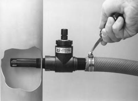
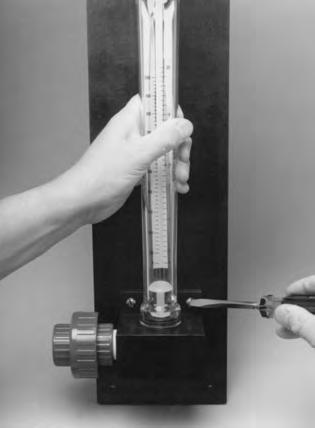
6 IMPORTANT Before proceeding, read the IMPORTANT NOTES AND WARNINGS in front of this manual. REGAL Gas Feed Systems are vacuum operated solution feed types designed for mounting directly to the cylinder valve of a 50 lb. cylinder or, to the top valve of a one ton container using a REGAL TAY-200 ton container adapter assembly or, to the valve of an approved gas manifold. The vacuum regulator mounts to the valve by means of a positive, heavy duty yoke clamp and is sealed against leakage by a lead gasket. The vacuum regulator has a built-in spring opposed diaphragm regulator and safety shut-off valve to maintain the proper operating vacuum levels in the system. Gas feed rate is manually adjusted. A highly efficient water powered, vacuum producing ejector is close coupled with the solution diffuser in systems to 500 PPD. Above 500 PPD, the solution diffuser is by others. All REGAL ejectors contain a back flow check valve. The REGAL Gas Feed System incorporates the very best available materials using the latest technology in design and construction. More than two dozen improvements have been made to reduce maintenance, simplify construction, and improve operation. GENERAL Each system consists basically of standard system components plus necessary water supply piping, parts, and extra accessories that may be desired. The standard system package includes:. The vacuum regulator with built-in vent. 2. The ejector assembly with back flow check valve, nozzle, and diffuser (when supplied). 3. The remote metering panel assembly with manual rate adjustment valve (ONLY ON SYSTEMS REQUIRING REMOTE METERING PANEL ASSEMBLIES). 4. Standard accessories and spare parts..0 INSTALLATION (See Drawing, 2 or 3). HANDLING OF CYLINDERS/CONTAINERS Chlorine, Sulfur Dioxide, and Ammonia gas is potentially dangerous. The following rules must always be adhered to:.. Never move a cylinder/container unless the valve protection domes and/or hoods are in place...2 Locate the cylinder/container where they will not be bumped or damaged...3 A safety chain should be placed around cylinders and secured to a wall or support. Ton containers should be secured in position using trunnions or other similar devices...4 As a rule of thumb, chlorine and ammonia cylinders and/or containers should be stored and used in an environment of 50 F minimum. Sulfur dioxide cylinders and/or containers should be stored and used in an environment of 70 F minimum..2 MOUNTING THE VACUUM REGULATOR.2. Remove the valve protection hood from the cylinders or the ton container..2.2 If a ton container, rotate the container until the two outlet valves are aligned vertically. This allows gas to be withdrawn from the top valve and liquid from the bottom valve. CONNECT TO THE TOP VALVE FOR GAS USE..2.3 Unscrew the cap nut covering the valve outlet..2.4 Remove any dirt that may be in the valve outlet or on the gasket sealing surfaces..2.5 Remove all shipping tape from the vacuum regulator s inlet. DO NOT REMOVE the filter that is inserted in the vacuum regulator s inlet..2.6 If the vacuum regulator is cylinder mounted, unscrew the yoke screw until the sliding bar can be pushed all the way back. Place a new /6 thick lead gasket over the vacuum regulator s inlet. NEVER REUSE A GASKET. Use a new one every time the regulator is removed from a cylinder. Mount the vacuum regulator on the cylinder valve by: a. placing the yoke over the valve, b. engaging the vacuum regulator inlet properly with the valve outlet, and c. carefully tightening the yoke clamping screw, using the integral tightening handle to compress the lead gasket. Excessive tightening can squeeze the lead gasket out of the joint and cause a leak and/or damage to the equipment. (Photo.).2.7 If container mounted, mount the vacuum regulator to the valve of a REGAL TAY-200 Ton Container Adapter Assembly by following the steps outlined in.2.6 above. a. Unscrew the yoke screw of the TAY-200 adapter until the sliding bar can be pushed all the way back. b. Place a NEW lead gasket over the inlet adapter of the TAY-200 and mount the TAY-200 with regulator installed to the top container valve BEING CAREFUL TO ALIGN THE REGULATORS INLET PROPERLY TO THE VALVES OUTLET. If not aligned properly, the inlet adapter WILL BE DAMAGED. c. Carefully tighten the yoke clamping screw of the TAY-200, using the integral tightening handle to compress the lead gasket. Excessive tightening can squeeze the lead gasket out of the joint and cause a leak and/or damage to the equipment. 6


7 DIFFUSER GASKET..2 DIFFUSER GASKET EJECTOR BODY NOZZLE GASKET

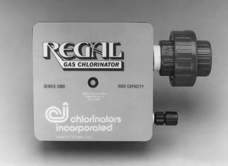
8 Drawing Typical installation of basic Model 20 type system. Drawing 2 Typical installation of a Multi-Point feed system. Ejectors installed as in Drawing. Drawing 3 Typical installation of a High Capacity Model /2000 PPD. 8
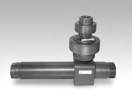
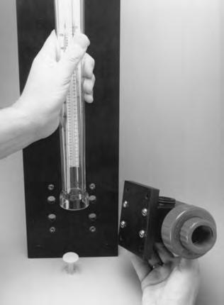
9 .2.8 If manifold mounted, mount the vacuum regulator to the appropriate valve of the manifold by following the steps outlined in.2.6 above. (Photo.8). a. Using NEW lead gaskets and approved flexible connection lines, auxiliary container valves, etc., connect each flexible connection line, auxiliary container valve, etc. from each cylinder or TOP container valve to the remaining manifold valves..3 INSTALLATION OF EJECTOR.3. The check valve in the ejector is designed so that the ejector may be installed in any position. The check valve assembly, components, and piping MUST be supported to prevent breakage due to water hammer, vibration, etc. A horizontal mounting of the ejector is preferred. BE SURE THE PROPER CHECK VALVE IS USED TO MATCH THE SYSTEM APPLICATION PRESSURE..3.2 The point of injection should be carefully chosen so that the water pressure is as low as possible. Vacuum is created in the ejector by the nozzle - actually a precision designed venturi - so water pressure to the nozzle must be high enough to overcome the total back pressure and create a strong jet in the nozzle..3.3 Ejectors to 500 PPD are designed to withstand static back pressures up to 200 psig (4. kg/cm2). However, due to possibilities of water line hammer in high pressure on-off systems, as well as special booster pump considerations, it is recommended that a factory representative, or Chlorinators Incorporated be consulted regarding installation details in systems over 00 psig (7 kg/cm2). Ejectors of 000/2000 PPD are designed to withstand static back pressures up to 70 psig (4.9 kg/cm2). However, due to possibilities of water line hammer in high pressure on-off systems, as well as special booster pump considerations, it is recommended that a factory representative, or Chlorinators Incorporated be consulted regarding installation details in systems over 50 psig (3.5 kg/cm2)..3.4 Generally, the amount of water (GPM) required to operate the ejector depends on the gas feed rate (lb/24 hrs, gms/hr, or kg/hr). The higher the gas feed rate, the greater the water flow needed. Refer to Application Bulletins 002 or 009 in Section 7.0 of this manual..3.5 Ejector water supply pressure must be greater than the pressure into which the gas solution is injected. The amount of pressure differential may vary with the particular application. Generally, the greater the pressure into which the gas solution will be injected, the greater must the differential pressure be. However, the minimum pressure differential and water flow for your installation should be determined prior to installation and start-up..3.6 Follow these steps for installing ejectors up to 500 PPD with close-coupled diffusers. a. Unscrew the diffuser from the assembly. DO NOT install the diffuser when assembled as damage may occur. b. Put teflon tape on the 3/4 pipe threads and screw the diffuser into the pipe. These are high impact plastic parts but, as with all plastic pipe fittings, care should be exercised in tightening. Tighten carefully with a properly adjusted wrench. Make sure that the holes in the spray diffuser are in the main stream. The end of an open end diffuser should not allow the strong solution to come in contact with any metal pipe or fittings as serious corrosion will occur (See Photo.5). c. Place a G-204 gasket into position on both the nozzle and the diffuser. Insert the nozzle through the check valve body (Photo.3) and screw into the diffuser until contact is made with both G-204 gaskets. Hold the check valve body against the diffuser at /8 turn COUNTER- CLOCKWISE from its final position (See Photo.4). At the same time, turn both the nozzle and the check valve body /8 turn clockwise to their final tightened position. The check valve may be installed in any position - up, down, or sideways. NOTE: A short length of hose is recommended between the ejector and rigid piping to absorb vibrations..3.7 Follow these steps for installing ejectors of 000/2000 PPD capacities. (See Drawing 3). a. The nozzle (water inlet) and throat (solution outlet) connections are 2 NPT for use with customer furnished fittings, flanges, unions, etc. b. The ejector s gas inlet is a NPT PVC union. c. Use teflon tape on all threaded connections. Tighten threaded connections carefully, using properly sized wrenches, being careful not to over tighten, as damage to the parts could result. MAKE SURE ALL RIGID PIPE RUNS ARE PROPERLY SUPPORTED..3.8 Other types of diffuser and ejector installations may be desired for certain applications. a. The ejector can be located near the other gas feed system components when required. A wall bracket can be provided for ejectors to 500 PPD. Various size adapters can be used on the solution outlet to accommodate hose or pipe. b. If the ejector is to be remotely installed with solution piping or hose running to the point of application, BE CERTAIN TO CUT OFF THE TIP OF THE STANDARD DIFFUSER BEFORE INSTALLING INTO THE PIPE OR HOSE. Failure to do this will result in excessive back pressure being created in the diffuser, preventing proper gas feed. 9

10 .6 UNION.7.8 0
11 WARNING: The 500 PPD ejector nozzle (50X) extends beyond the ejector body and the end of the E-540 nozzle retainer. DO NOT cut off the end of the nozzle. c. The entire ejector assembly may be submerged in an open channel or tank. d. Corporation cock type diffusers, ball valves, etc., can be used as required if properly sized..4 PIPING OF EJECTOR (See Drawing or 3).4. For most installations, the ejector water supply line should be brought to within 3-5 feet of the nozzle with rigid PVC or iron pipe. A 000/2000 PPD ejector will be directly connected to rigid PVC pipe on both sides..4.2 A shut-off valve followed by a Y-strainer and the ejector is recommended to enable servicing when necessary..4.3 A pressure gauge between the Y-strainer and the ejector is recommended..4.4 For 500 PPD and below ejectors, connect a short length of hose between the end of the rigid incoming water line and the ejector nozzle. Clamp the hose securely at both ends with single or double hose clamps (Photo.5)..5 CONNECTING VENT LINES.5. Every REGAL gas feed system incorporates a vent to allow pressurized gas an avenue of escape when necessary. Venting occurs when dirt or impurities enter the vacuum regulator inlet valve plug and seat area, preventing a bubble tight closure of the valve plug..5.2 Appropriate size flexible tubing is used for all vent connections. Use enough length to allow movement of the vacuum regulators when necessary..5.3 Route the tubing to a safe location outside the building. The end of the vent line should point down to prevent rain water from entering, and should be screened to keep insects from getting in and building nests..6 CONNECTING VACUUM LINES OR PIPING.6. On 500 PPD and below systems, flexible vacuum tubing is used to connect the various system components (Drawing # or #2). a. Remove connector nuts from vacuum connections and slip onto tubing. Using appropriate lengths of tubing, push onto connectors and tighten connector nuts HAND TIGHT..6.2 On 000/2000 PPD systems minimum Sch. 80 PVC pipe and fittings are used to connect the various system components (See Drawing No. 3). NOTE:. When 500 PPD and below systems are supplied with a remote metering panel assembly or assemblies, the rate adjustment valve is removed from the vacuum regulator and replaced with a non-adjustable plug. The metering tube normally furnished in the vacuum regulator is replaced with a plain glass tube without a float. 2. The metering panel assembly, which includes the metering tube and the manual rate adjustment valve, is designed for wall mounting using appropriate fasteners..6.3 Each additional point of application (all capacities) consists of an additional metering panel assembly with manual rate adjustment valve, and an additional ejector assembly. On capacities of 500 PPD and below, each additional feed point includes a length of flexible vacuum tubing and a tubing connector tee fitting (See Drawing No. 2)..7 ADDITIONAL INSTALLATION SUGGESTIONS.7. Many operators find it convenient to install a hook on the wall behind the cylinders or alongside the containers. When changing cylinders/containers, the vacuum regulator can easily be hung on this hook..7.2 An appropriate scale should be used to weigh the contents of the cylinders/containers to determine the amount of chemical remaining. 2.0 START-UP 2. CHECK EJECTOR (See Photo.5 or.7) 2.. The ejector assembly is the heart of the gas feed system. It creates the vacuum necessary to operate the remaining system components. Unless the ejector is creating a vacuum, the system WILL NOT WORK. To check ejector operation: a. Remove the vacuum tubing from the ejector tubing connector or unscrew the PVC union at the ejector vacuum connection. b. With the booster pump running or the pressurized water supply connected, open the ejector water line supply valve and any other valves that may exist between the ejector outlet and the point of chemical application. The ejector should now be in operation and creating a strong vacuum. c. Check for proper operation by placing your finger or hand over the vacuum connection opening. If there is no vacuum, refer to Section 7.0 and be certain there is enough supply pressure and the nozzle or piping is not plugged. Proper vacuum must exist before proceeding.
12 d. Shut off the water supply to the ejector and make sure no water comes out of the vacuum connection opening. If water is observed leaking past the check valve, see Section 4.4 and correct before proceeding. Once the problem is corrected, cycle the ejector on and off a few times to make sure the check valve is tightly sealed. Water leaks at this point CANNOT be tolerated. e. Repeat this procedure for all ejectors present. f. Reconnect the vacuum tubing or piping and leave the ejector running. On 000/2000 PPD ejectors, make sure the o-ring is not lost from the union connection. 2.2 CHECK VACUUM REGULATOR (See Photo. or.6) 2.2. With the ejector operating and the gas cylinder(s)/ container(s) still closed, the ball or float in the metering tube will remain at the bottom. If it does not, or if it bounces up and down, there is either a leak at the lead gasket where the vacuum regulator connects to the cylinder/container/manifold valve, or a loose connection in the system. Check and correct The supply indicator on the face of the vacuum regulator should be below the surface of the regulator body, indicating an out of gas condition Turn the rate valve on the vacuum regulator (or on the remote metering panel assembly) counterclockwise a few turns, to be sure the float remains at the bottom of the metering tube Close the ejector water supply valve to stop operation of the ejector Disconnect the flexible vacuum tubing (or disconnect the vacuum union) at the vacuum regulator to allow air to enter the system. Reconnect the vacuum line Open and immediately close the gas valve of the cylinder/container Chlorine and sulfur dioxide leaks are best located using a dauber moistened with commercial 26 degree Baume aqueous ammonia (household ammonia is not strong enough). A white cloud will form at the site of any leak. A plastic squeeze bottle which directs ammonia vapors, NOT LIQUID, at the joint being tested may also be used. Ammonia leaks are best located using moist litmus paper which turns color on exposure to ammonia fumes or by using sulfur dioxide or strong chlorine bleach fumes which both form a heavy white smoke when mixed with ammonia vapors. NOTE: If a pressure manifold system is being used, begin checking for leaks at the furthest cylinder/container connection. Check small sections of the manifold at a time until the entire manifold is found to be leak tight. When a leak is detected the system must be depressurized before corrective action is taken. NOTE: If the REGAL Vacuum Regulator is mounted on a ton container using a REGAL TAY-200 Ton Container Adapter Assembly, OPEN the valve on the TAY-200 Assembly /4 - /2 turn and repeat steps and If no leaks were detected, open the gas cylinder/ container/manifold valve(s) /4 turn, leave open and recheck for leaks one more time Turn on the water supply to the ejector(s) and adjust the gas feed rate to the desired setting. NOTE: NEVER use the rate valve to shut off the gas supply. This valve is for adjusting the gas feed rate only. To shut off the gas supply, close the cylinder/container/manifold valve(s). 3.0 SHUT-DOWN 3. Shut off the gas cylinder/container valves leaving all other gas pressure valves open. a. The ejector should be running. The out of gas indicator pin should be recessed below the surface of the vacuum regulator. WARNING: Even if the gas feed rate drops to zero as evidenced by the position of the ball or float in the metering tube and/or a recessed status indicator pin, and even if the supply container appears to be empty, SOME LIQUID CHEMICAL MAY STILL BE PRESENT. NEVER disconnect the vacuum regulator from the cylinder/ container/manifold valve until ALL cylinder/container/manifold valves are FULLY CLOSED or a highly dangerous chemical leak causing severe injuries or death could occur. 3.2 Shut off the water line supply valve or booster pump to the ejector. 3.3 When changing the gas cylinders/containers, follow the procedure on the cylinder/container changing chart supplied with your REGAL gas feed system. 2
13 Care and Maintenance of your REGAL Gas Feed System GENERAL This section covers all phases of service on REGAL Gas Feed Systems. Normally it is not necessary to completely disassemble the systems components unless it is to be cleaned throughout, or has been severely flooded. DO NOT DISASSEMBLE THE UNITS MERELY FOR THE SAKE OF DISASSEMBLY. All units have been factory tested and are in A condition when they are shipped. This text describes some of the things that can cause a REGAL gas feed system to stop working. Read it carefully and find out what the problem is, before attempting to correct it Safety shut off inlet valve plug and seat VENTING (Photo 5.4 & 5.5). Gas leaking out of the vent is an indication of a leak at the inlet valve plug and seat. The usual cause is dirt on the valve seat. Test to make certain the problem is a leak at this point. a. Shut off water supply to ejector assembly. b. Submerge the end of the vent tubing in a glass of water. Continuous bubbling is an indication of a gas leak. c. Before removing the unit from the cylinder/ container/manifold, close the cylinder/ container/manifold valve, turn on the water supply, and allow the vacuum regulator to operate until the metering ball or float drops to the bottom (ZERO). NOTE: A gas leak around the S-404 and S-406 o-rings could also result in a vent leak. 4.0 TROUBLESHOOTING HINTS REGAL Gas Feed Systems will require minimum service if operated with reasonable care. Problems which could arise are listed below. IMPORTANT: BEFORE PROCEEDING, READ THE PRECAUTIONS FOR PERSONAL AND SYSTEM PROTECTION AT THE FRONT OF THIS MANUAL. 4. GAS PRESSURE LEAK There are four possible points of gas pressure leaks. These are rare, but if a gas leak is detected, it should be immediately located and stopped. Even small leaks can create a safety hazard and cause serious corrosion to equipment in the area. 4.. Cylinder/container/manifold valve packing. The cylinder/container/manifold valves are high quality valves designed specifically for the gas service intended. Chemical suppliers should service these valves at each filling, and leakage at this point is unusual. Should a leak develop, tighten the valve packing nut without exerting excessive force. If this does not eliminate the leak, close the valve and call the chemical supplier The lead gasket seal between the vacuum regulators and the cylinder/container/manifold valves. A leak at this point could be caused by reusing a lead gasket, by dirt on the gasket surfaces, under or over tight connections, or by installation without a gasket, or the use of a fiber type gasket instead of lead. ALWAYS USE A NEW LEAD GASKET. Make certain the gasket and gasket surfaces are clean and smooth. Tighten clamps, but not excessively Vacuum regulator adapter face seal S-404. Gas leaking out between the back body and the yoke assembly usually indicates a leak at the o-ring seal between the inlet valve capsule and the inlet adapter. The usual causes are listed below. See Section 5.2. a. Improper tightening of the inlet valve capsule after disassembly. b. Dirt or impurities on the o-ring or sealing surfaces. c. A leak around the S-404 and S-43 o-rings could result in a gas leak between the yoke body bar and the back body. 4.2 LOSS OF GAS FEED 4.2. No vacuum. This can readily be checked by removing the gas line at the ejector vacuum inlet and holding your finger or hand over the opening. Suitable vacuum will exert a strong pull. If there is no vacuum, the ejector nozzle may be plugged. Refer to Section 5.6 or Insufficient water pressure to operate the ejector. This can be readily checked as in 4.2. above No gas supply. This should be obvious. When the gas supply becomes empty, the metering ball or float will not indicate above zero gas feed rate, and the supply indicator pin will be below the vacuum regulator face Plugged inlet filter. Dirt from the cylinder/container may completely plug the high efficiency, porous filter. The filter may be removed for inspection and cleaning. See Section 5., Cleaning Safety Shut-Off Valve and Seat Poor air circulation around the cylinder/container resulting in low cylinder/container pressure and possible frost build-up. 3
14 4.3 STICKY BALL IN METER TUBE 4.3. Deposits a. The gas may contain traces of organic compounds which deposit on the ball or float or the inside of the glass tube. This deposit is often sticky, causing the ball or float to adhere to the surface of the glass, resulting in erratic operation. When this occurs, it is necessary to remove the flow meter tube assembly from the unit for cleaning. The cleaning procedure is outlined in Section 5.8, 5.9 or 5.0. b. The frequency of cleaning depends on a number of factors notably the quality of the chemical and the operating temperature of the installation Moisture in the system. a. In the normal course of operation, moisture should not be present. However, it is possible when changing cylinders or containers, that very moist air could be drawn into the inlet or the vacuum regulators. This can cause the metering ball or float to become sticky particularly at the bottom (small end) of the tube. b. If the vacuum regulator has been previously flooded (See Section 4.4) it is possible that all moisture has not been removed from all gas passageways in the system. c. A severe vacuum leak can allow moist air to enter the system (See Section 4.4). 4.4 WATER IN SYSTEM COMPONENTS - FLOODING 4.4. During normal operation, vacuum is drawing gas through the system and water cannot enter. When the system is shut down and vacuum is lost, water is prevented from backing up by the check valve in the ejector assembly. Any water observed in the metering tube or any other system component indicates a failure of the check valve. If the check valve has failed: a. Close the cylinder/container/manifold valve the vacuum regulator is attached to. b. Shut off the water supply to the ejector and the water in the main, so there is no pressure in the ejector piping. c. Remove the vacuum tubing or piping from the ejector and follow instructions for Cleaning and Replacing the Ejector Check Valve, Section 5., 5.2, 5.3, 5.4 or 5.5. d. Remove the vacuum regulator from the cylinder/container/manifold valve. Carefully follow instructions in Section 5.2 to be sure all moisture is removed from ALL system components prior to reassemble and start-up. e. If the system is using a remote metering panel assembly, remove the metering tube and follow instructions in Section 5.8, 5.9 or 5.0 Cleaning Metering Tube VACUUM LEAKS 4.5. For best operation, all parts of the system should be airtight, since vacuum leaks will permit air to enter. All units are vacuum tested at the factory prior to shipment, so a vacuum leak in a new unit is unlikely. Furthermore, it is very unusual for leaks to develop during operation unless the unit has been disassembled or physically damaged A simple test determines whether the system is free of vacuum leaks: a. Operate the system at an arbitrary gas feed setting. b. Shut off the cylinder/container/manifold valve that the vacuum regulator is attached to. IT IS ASSUMED THAT IT WILL SHUT TIGHTLY. A defective valve will give erroneous results. c. The float or ball in the metering tube should drop to zero. This may take a minute or two depending upon capacity. If the ball or float does not drop to the bottom, this indicates a vacuum leak at some point in the system, usually between the vacuum regulator inlet and the metering tube. d. When the ball or float drops to zero, shut off the ejector water supply. Note that the indicator pin in the center of the vacuum regulator body is recessed below the surface of the body, indicating an out of gas condition. With a perfectly tight system, this condition will remain. Usually a 5 to 0 minute check is all that is needed. If a leak exists in the system, the diaphragm assembly will move forward causing the indicator pin to reset with the tip protruding slightly The most common cause of vacuum leaks is improper assembly of the system components after they have been taken apart for servicing The most common points of leakage are: a. Gas metering tube seals (o-rings or gaskets). Check to make sure the meter tube o-rings or gaskets are in good condition and properly installed. Metering tube gaskets can be reused, but they should be turned over. b. Rate valve o-rings. Rate valve o-rings may become worn. Fouling of the surfaces might cause abrasion of the o-ring surface. Check and replace as necessary. c. Sealing surface at main diaphragm. An imperfection or a speck of dirt on this surface during reassembly may cause a leak, but REGAL s unique use of a compression sealing o-ring makes this unlikely. d. Vacuum connections. Check all vacuum tubing and piping for leaks and cracks. On 000/2000 PPD systems, make sure all union o-rings are in place. e. Other possible, but less common points of leakage:. O-ring in connecting passage of bodies. 2. O-ring at inlet capsule. 3. Vent seal on diaphragm plate. 4. Back body inlet seal. 5. Diaphragm plate seal.
15 4.6 FAILURE TO REPEAT SET FEED RATE 4.6. On start-up, a system with a dirty meter tube or rate adjustment valve may not repeat. This is particularly true of low capacity systems of 0 PPD or less. Correction of this situation can be accomplished by: a. Cleaning the rate adjustment valve as outlined in Section 5.8, 5.9 or 5.0. b. Cleaning the metering tube as outlined in Section 5.8, 5.9 or 5.0. The frequency of cleaning depends on the quality of the gas chemical being used Failure to repeat may also occur if any of the system components have been flooded and moisture remains in the metering and rate adjustment area. 4.7 ICING OF THE METERING TUBELIQUID 4.7. If ice is observed forming on the metering tube assembly, it is a definite indication that LIQUID chemical has entered the vacuum regulator from the source of supply. While this is extremely rare, our experience has shown that suppliers have been known to overfill cylinders/containers from time to time. Also, if the cylinders are tipped over while the vacuum regulator is attached and operating, liquid could be drawn into the system. If manifold assemblies are being used, make sure the manifold contains a suitable liquid trap (drip leg) with an appropriate (WORKING) heater installed If the system has been subjected to liquid chemical, do the following: IMPORTANT: Before proceeding, read the Precautions for Personal and System Protection at the front of this manual. a. Shut off the cylinder/container/manifold valves. b. Leave the ejector running and developing a vacuum in the system. c. Remove the vacuum regulator from the cylinder/container/manifold valve. d. Quickly remove the vacuum tubing from the vacuum regulator and observe that the supply indicator is above the surface. e. Reconnect the vacuum tubing or piping and open the rate adjustment valve to maximum. The system will now draw air into the vacuum regulator inlet, vaporizing any remaining liquid. Allow the system to draw air for several minutes. f. Shut off the ejector. g. Either OUTDOORS OR IN A WELL VENTILATED ROOM, follow instructions in Section 5.2, titled Disassembly of vacuum regulator body. Clean all parts with denatured alcohol, and replace any parts that show signs of liquid chemical attack. h. Reassemble and follow start-up procedure in Section SERVICE/DISASSEMBLY PREVENTIVE MAINTENANCE SCHEDULE REGAL SYSTEMS AND SYSTEM COMPONENTS The best, most cost effective, and easiest way to assure that your gas feed system and equipment will provide continuous, dependable, trouble free operation, is to establish a PREVENTIVE MAINTENANCE SCHEDULE. This will assure minimum unscheduled down time. The maintenance schedule should be in writing and include as a minimum, the date of installation, the scheduled date of maintenance, the actual date the maintenance was performed, the parts used, and any applicable notes. All REGAL products are engineered for easy maintenance and this manual provides step by step procedures to properly service and maintain each component within the system. It is your (the customer s) responsibility to establish and undertake a SCHEDULED MAINTENANCE PROGRAM. To support this program, we have available a variety of REPAIR KITS containing the parts we feel you may need for minor emergency repairs. We recommend that these kits be available in your stock at all times. When this kit, or any parts are used, the kit should be replaced immediately. This manual contains complete parts lists for each system component. As such, you can order and stock additional parts as deemed necessary. AT A MINIMUM, THIS EQUIPMENT SHOULD RECEIVE SCHEDULED MAINTENANCE AT LEAST ONCE A YEAR. Depending on the installation, application, location of components, quality of gas, etc., this equipment may need scheduled maintenance more than once a year. This is something that needs to be determined on a job by job basis. Spare parts and/or repair kits may be ordered directly from the company who supplied your equipment, or they may be ordered directly from our inventory in Stuart, Florida. IMPORTANT: Maintenance on REGAL Systems or System Components should be performed by competent personnel familiar with this type of equipment such as authorized REGAL Dealers or Chlorinators Incorporated themselves. WARNING: Even if the gas feed rate drops to zero as evidenced by the position of the ball or float in the metering tube and/or the supply indicator pin is below the surface of the head, and even if the supply container appears empty, SOME LIQUID CHEMICAL MAY STILL BE PRESENT. NEVER disconnect the vacuum regulator from the cylinder/ container/manifold valve until ALL cylinder/container/manifold valves are FULLY CLOSED or a highly dangerous chemical leak causing sever injuries or death could occur. 5


16 CHECK VALVE CHECK VALVE SEAT TEFLON TAPE USE FIGURE 8 PATTERN ONLY DIFFUSER RATE VALVE SEAT GASKET RATE VALVE PLUG EJECTOR BODY NOZZLE GASKET RATE VALVE STEM SEAL RATE VALVE SEAT RATE VALVE SEAT SEAL COTTON SWAB PIPE CLEANER
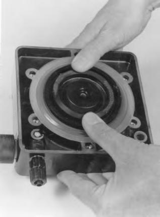
17 5. HIGH PRESSURE EJECTOR CHECK VALVE TO 500 PPD - CLEANING AND REPLACING (See appropriate Parts Drawing A-920/A-922/A-925, A-920S/A-922S/A-925S or A-920A) 5.. A check valve is installed in the ejector assembly to prevent water from backing into the system when the ejector is shut off. The check valve design is such that it is extremely difficult for dirt to get under the valve, but it might, if large amounts of sand or other impurities are present in the water supply; and dirt could possibly enter from the gas side. To remove and clean the valve, proceed as follows: a. Close the cylinder/container/manifold valve(s) before working on any system component. b. Shut off the water supply to the ejector and the water pressure in the main. c. Remove vacuum tubing from the fitting on top of the ejector assembly. d. Unscrew the check valve seat from the ejector body using pliers if necessary. e. Carefully lift the edge of the check valve (Photo 5.) and inspect. f. If the check valve and seat are in good condition, clean both the valve and the seating surface and reinstall the check valve seat into the ejector body. Use a thin film of Vaseline or Dow Corning DC33 on the seat o-ring and seat gasket as necessary. DO NOT USE ANY OTHER PETROLEUM BASED GREASES OR OILS. g. Make sure the check valve seat is screwed completely into the ejector body. USE NO TOOLS. HAND TIGHTEN ONLY. h. Pressurize the ejector and cycle several times before reconnecting the vacuum tubing to make sure the check valve is sealing properly. i. If wear or damage is noted, the check valve must be replaced. If the check valve needs to be replaced, proceed as follows: ) Grasp the outer edges of the check valve and apply a steady pulling force until the umbrella shaped stem pops free. Be certain it is completely removed. 2) Examine the check valve seat sealing surface for deposits, and clean with denatured alcohol. 3) Check the seat sealing surface with a straight edge to be certain it is completely flat. If the center is slightly raised, you will see light under the straight edge, or it will rock over the center. If the seat sealing surface is not flat, use a very fine sandpaper or emery cloth on a flat surface (e.g., plate glass) and gently move the check valve seat in a figure 8 pattern (Photo 5.2). Do not rub back and forth, or the seat will become distorted. 4) Wet the tip of the new check valve with a very light film (make shiny only) of Vaseline or Dow Corning DC33. Put the tip of the check valve in the center check valve seat hole and, using the handle of a screwdriver or other rounded object, push against the center of the check valve until the tip snaps into the seat (Photo 5.3). DO NOT TWIST THE CHECK VALVE OR DAMAGE MAY OCCUR. j. When reinstalling the check valve seat, put a thin film of Vaseline or Dow Corning DC33 on the seat o-ring and seat gasket for lubrication. DO NOT USE ANY OTHER PETROLEUM BASED GREASES OR OILS. k. Screw the check valve seat clockwise into the ejector body. Use no tools. Hand tighten only. l. Pressurize the ejector and cycle several times before reconnecting the vacuum tubing to ensure that the check valve is sealing properly. 5.2 OPTIONAL LOW PRESSURE EJECTOR CHECK VALVE TO 500 PPD - CLEANING AND REPLACING (See appropriate Parts Drawing A-92/A-923/A-926, A-92S/A-923S/A-926S or A-92A) 5.2. To remove and clean the check valve, proceed as follows: a. Close the cylinder/container/manifold valve(s) before working on any system component. b. Shut off the water supply to the ejector and the water pressure in the main. c. Remove the vacuum tubing from the fitting on top of the ejector assembly. d. Unscrew (counterclockwise) the entire check valve assembly out of the ejector body. Make sure the seat gasket remains in place and is in good condition. Replace if necessary. e. Using a spanner wrench in the holes located in the underside of the outlet body, unscrew the outlet body from the clamping ring. Do not lose the spring or the diaphragm assembly. ) The diaphragm is made from a special corrosion resistant plastic. Inspect it carefully for nicks or cuts. Replace as necessary. 2) The check valve action is accomplished by the diaphragm bolt sealing tightly on the o-ring located in the center of the inlet body when the ejector is shut off. As such, the diaphragm bolt sealing surface and the o-ring must be free of dirt or impurities that may prevent an effective seal. Clean or replace as necessary. f. Reassemble by reversing steps a through d above. 7


18 YOKE ASSEMBLY INLET ADAPTER PLUG ADAPTER FACE SEAL INLET ADAPTER INLET VALVE PLUG VENT PLUG SPRING GUIDE INLET SPRING INLET ADAPTER PLUG INLET VALVE SEAT VENT PLUG INLET VALVE PLUG RECOMMENDED FILTER INSTALLATION TYP. SECTION OF CHLORINATOR OR SULPHONATOR / 32 (.8 mm) SPACING Y-275 INSTALLATION
19 5.3 OPTIONAL A-927 HIGH/LOW EJECTOR CHECK VALVE TO 00 PPD - CLEANING & REPLACING (See Parts Drawing A-927/A-927A) 5.3. The high/low check valve assembly is installed in the ejector assembly to prevent water from backing into the system when the ejector is shut off. If flooding has occurred or maintenance is due, proceed as follows: a. Close the cylinder/container/manifold valve (s) before working on any system component. b. Shut off the water supply to the ejector and the water pressure in the main. c. Remove vacuum tubing from the fitting on top of the ejector assembly. d. Unscrew (counterclockwise) the entire check valve assembly out of the ejector body. Make sure the seat gasket remains in place and is in good condition. Replace if necessary. e. Grasp the outer edges of the check valve, E-250, and apply a steady pulling force until the umbrella shaped stem pops free. Be certain it is completely removed. f. Examine the check valve seat sealing surface for deposits, and clean with denatured alcohol. g. Check the seat sealing surface with a straight edge to be certain it is completely flat. If the center is slightly raised, you will see light under the straight edge, or it will rock over the center. If the seat sealing surface is not flat, use a very fine sandpaper or emery cloth on a flat surface (e.g., plate glass) and gently move the check valve seat in a figure 8 pattern (Photo 5.2). Do not rub back and forth, or the seat will become distorted. h. Using a new E-250, wet the tip of the new check valve with a very light film (make shiny only) of Vaseline or Dow Corning DC33. Put the tip of the check valve in the center check valve seat hole and, using the handle of a screwdriver or other rounded object, push against the center of the check valve until the tip snaps into the seat (Photo 5.3). DO NOT TWIST THE CHECK VALVE OR DAMAGE MAY OCCUR. i. Using a spanner wrench in the holes located in the underside of the outlet body, unscrew the outlet body from the clamping ring. Do not lose the spring or the diaphragm assembly. ) The diaphragm is made from a special corrosion resistant plastic. Inspect it carefully for nicks or cuts. Replace as necessary. 2) The check valve action is accomplished by the diaphragm bolt sealing tightly on the o-ring located in the center of the inlet body when the ejector is shut off. As such, the diaphragm bolt sealing surface and the o-ring must be free of dirt or impurities that may prevent an effective seal. Clean all parts or replace as necessary. Always use a new check valve seal o-ring. j. Reassemble, using a spanner wrench in holes, located in underside of outlet body. Tighten outlet body and clamp ring. k. When reinstalling the check valve assembly in ejector, put a thin film of Vaseline or Dow Corning DC33 on the seat o-ring and seat gasket for lubrication. Use very sparingly (make it shiny only). DO NOT USE ANY OTHER PETROLEUM BASED GREASES OR OILS. l. Screw the check valve assembly clockwise into the ejector body. Use no tools. Hand tighten only. m. Pressurize the ejector and cycle on and off several times before reconnecting the vacuum tubing to ensure that the check valve is sealing properly. Follow start-up procedures in Section OPTIONAL DUAL CHECK VALVE EJECTOR TO 500 PPD (See Drawing A-950/A-949) The REGAL A-950 Dual Check Valve Ejector has a ball check valve as the primary check valve backed up by a spring loaded o-ring/poppet check valve. To service this check valve, proceed as follows: 5.4. Shut off the water supply to the ejector and the water in the main Remove the vacuum tubing. NOTE: CHLORINE GAS TRAPPED BETWEEN THE VACUUM REGULATOR AND EJECTOR MAY DISCHARGE INTO THE ATMOSPHERE WHEN THE VACUUM LINE IS DISCONNECTED Unscrew (counterclockwise) the complete A-949 Check Valve Assembly from Ejector body E-557. A properly sized wrench can be used on the machined flats of Bottom Body E-552 if necessary to loosen the ejector body. DO NOT USE PLIERS Make sure the o-ring S-43 located on Bottom Body E-552 is in good shape. Replace as necessary To gain access to the Check Valve Components unscrew (counterclockwise) Clamp Ring E-30 from Bottom Body E-552 and lift the Top Body E-55 with the Clamp Ring off of the Bottom Body. BE CAREFUL NOT TO LOSE POPPET E-554, SPRING E-555, OR O-RING S-46 AS THESE ITEMS CAN EASILY FALL OUT Inspect the o-ring S-48 located on the E-554 Poppet and replace as necessary. THIS IS THE SECONDARY CHECK VALVE SEAL AND MUST BE IN LIKE NEW CONDITION Inspect and clean as necessary the flat surface inside Top Body E-55. Since this is the sealing surface for the S-48 sealing o-ring. THIS SURFACE MUST BE CLEAN AND PERFECTLY FLAT. 9


 GAP")

20 ADAPTER OD SEAL BACK BODY BACK BODY INLET SEAL FRONT BODY BACK DIAPHRAGM PLATE BODY SEAL TUBE BODY SEAL DIAPHRAGM ASSEMBLY DIAPHRAGM FRONT DIAPHRAGM PLATE DIAPHRAGM BODY SEAL LEAVE APPROX. /6 (.6mm) GAP ALIGN BODY SEAL TUBE OPENINGS
21 5.4.8 The primary check valve is located inside Bottom Body E-552. To gain access to the primary check valve, proceed as follows: a. Using Drawing A-950/A-949 as a guide, carefully unscrew (counterclockwise) the Spring/Ball Retainer E-553 from Bottom Body E-552. THE OUTER CIRCUMFERENCE OF THE SPRING/BALL RETAINER IS KNURLED TO MAKE IT EASIER TO UNSCREW. ONCE REMOVED, THE BALL E-556 IS FREE TO FALL OUT. BE CAREFUL NOT TO LOSE OR DAMAGE THE BALL. b. Inspect the Ball E-556 and make sure it is free of all deposits, nicks, and pits. If in doubt, replace as necessary. c. Poppet E-553 contains two o-rings. The S-45 o-ring is a sealing o-ring and MUST remain in its groove when reassembling the check valve components. Inspect this o-ring for wear and replace as necessary. d. The second o-ring S-47 is a critical o-ring as it is the sealing surface for the primary check device (Ball E-556). This o-ring is located in an undercut groove at the base of Spring/Ball Retainer E-553. If o-ring S-47 shows any signs of wear or, if o-ring S-47 is flattened due to the check action of Ball E-556, replace with a new one Clean all check valve parts with warm water and/or a mild solvent such as denatured alcohol Make sure all parts are thoroughly dry and all o-rings are in place and reassemble by reversing the steps outlined in Section EJECTOR CHECK VALVE 000/2000 PPD - CLEANING OR REPLACING (Refer to Drawing A-2920/2922) 5.5. A-2000 CHECK VALVE A check valve is installed in the ejector assembly to prevent water from backing into the system when the ejector is shut off. The check valve design is such that it is extremely difficult for dirt to lodge under the valve, but it might, if large amounts of sand or other impurities are present in the water supply; and dirt could possibly enter from the chemical side. To remove and clean the valve, proceed as follows: a. Close the manifold valve that the vacuum regulator is attached to before working on any system components. b. Shut off the water supply to the ejector and the water pressure in the main. c. Open the PVC vacuum union MS-9 by unscrewing (counterclockwise) the union ring and move the vacuum piping out of the way. Be careful not to lose the vacuum union o-ring. NOTE: CHLORINE GAS TRAPPED BETWEEN THE VACUUM REGULATOR AND EJECTOR MAY DISCHARGE INTO THE ATMOSPHERE WHEN THE VACUUM LINE IS DISCONNECTED. d. Using Parts List Drawing A-2000 as a guide, unscrew Clamp Ring CV-2004 and lift the Top Body CV-2002 with Clamp Ring off Bottom Body CV-200 and set aside. BE SURE NOT TO LOSE O-RING S-804. e. Carefully lift out Poppet CV-2003 and Spring CV f. Poppet CV-2003 contains an o-ring S-805 which is the check valve seal. THIS O-RING MUST BE IN PERFECT SHAPE, FREE OF NICKS, CUTS, ETC. IF NECESSARY, REPLACE IT WITH A NEW ONE. IF O-RING S-805 SHOWS SIGNS OF BEING FLATTENED DUE TO THE ACTION OF THE NEW CHECK VALVE, REPLACE IT WITH A NEW ONE. g. Inspect the flat surface inside Top Body CV-2002 to be sure it is flat and clean. THIS IS THE SURFACE O-RING S-805 SEALS AGAINST. h. Clean all check valve parts with warm water or a mild solvent such as denatured alcohol and dry thoroughly. i. Reassemble the ejector check valve assembly by reversing steps a through e. 5.6 CLEANING/INSPECTION OF EJECTOR NOZZLE TO 500 PPD 5.6. To remove the ejector nozzle for cleaning, the water pressure in the main must first be shut off unless the ejector was initially installed with a valve on the inlet side and a ball valve or corporation stop in the outlet, so that isolation of the ejector is possible. a. Close the cylinder/container/manifold valve(s) before working on any system component Remove the ejector supply hose and gas vacuum tubing from the ejector assembly Rotate the complete ejector body counterclockwise, making certain that the solution diffuser remains fixed in the solution piping or main (Photo.3) Unscrew the nozzle from the ejector body. Check the gaskets located in each side of the body and replace if necessary (Photo.3) Nozzle plugging can be caused by: a. A piece of foreign material (pipe sealer, stone, or dirt) lodging in the nozzle orifice. This can usually be blown out in the reverse direction. DO NOT USE SHARP TOOLS OR ALTER THE SIZE OF THE ORIFICE IN ANY WAY. b. Excess plastic pipe solvent or glue used during initial installation running into the orifice area of the nozzle. If this cannot be cleaned out easily, the nozzle may need to be replaced. 2


22
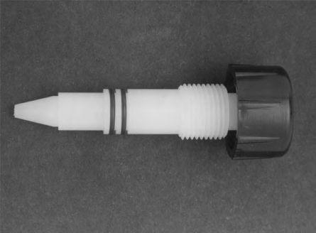
23 c. Build-up of deposit. This could be a chemical build-up of iron, manganese, or some other material which usually can be removed by immersing the nozzle in muriatic acid and rinsing. CAUTION: READ ALL WARNING LABELS ON THE MURIATIC ACID CONTAINER, AND AVOID SKIN CONTACT. It is recommended that safety goggles or face shield be used when working with any strong acid. Some waters are such that build-up of deposits can cause an ejector to become inoperative in a short period of time To reinstall the nozzle: a. Insert the nozzle through the ejector body and screw into the solution diffuser. Make sure the gaskets are in place and in good condition (Photo.3). b. Hold the ejector body against the diffuser at /8 turn counterclockwise from its final position (Photo.4). c. Screw the nozzle into the diffuser by hand until contact is made against both gaskets. d. Turn the ejector body and the nozzle at the same time, /8 turn clockwise to the final tight position (Photo.4). THE PARTS ARE PLASTIC, AND EXCESSIVE TIGHTENING MAY CAUSE BREAKAGE. DO NOT USE TOOLS. e. Reinstall the ejector supply hose and vacuum tubing (Photo.5) Open all valves and check for proper operating vacuum. 5.7 CLEANING/INSPECTION OF 000/2000 PPD EJECTOR NOZZLE 5.7. The ejector nozzle and throat thread into the ejector body. To inspect and clean these parts, proceed as follows: a. Close the manifold valve that the vacuum regulator is attached to before working on any system components. b. Shut off the water supply pressure to the ejector, and close any valves in the chlorine solution line so as to isolate the ejector assembly. c. Open the PVC vacuum union MS-9 by unscrewing (counterclockwise) the union ring and move the vacuum piping out of the way. NOTE: CHLORINE GAS TRAPPED BETWEEN THE VACUUM REGULATOR AND EJECTOR MAY DISCHARGE INTO THE ATMOSPHERE WHEN THE VACUUM LINE IS DISCONNECTED. Be careful not to lose the vacuum union o-ring. d. Open or disconnect the 2 unions, flanges, fittings, etc., holding the ejector assembly into the pipeline, and remove the ejector. WHEN REMOVING AND/OR INSTALLING THE COMPLETE EJECTOR ASSEMBLY, BE CAREFUL NOT TO LOOSEN OR OVER- TIGHTEN THE NOZZLE AND THROAT WHICH COULD CAUSE DAMAGE TO THESE PARTS AND/OR WATER LEAKS. e. Carefully clean or remove any foreign material that may have accumulated in the ejector nozzle or throat area, being careful not to scratch or mar the nozzle orifice. NOTE: DO NOT USE SHARP TOOLS OR ALTER THE SIZE OF THE ORIFICE IN ANY WAY. f. If chemical deposits have built up in the nozzle or throat area, immerse the part in muriatic acid. REMOVE ALL O-RINGS OR GASKETS FIRST. IMPORTANT: READ ALL WARNING LABELS ON MURIATIC ACID CONTAINER AND FOLLOW ALL SAFETY INSTRUCTIONS. g. Reassemble by reversing steps a through e. 5.8 CLEANING MANUAL RATE ADJUSTMENT VALVE AND METERING TUBE ON SYSTEMS TO 500 PPD (MODELS 20, 20-, 220, 250, 720 AND 750 ONLY) NOTE: Close the cylinder/container/manifold valve(s) before working on any system component Unscrew and remove the rate valve plug assembly from the top of the metering tube (Photo 5.5) Insert the rate valve tool supplied with the gas feed system through the side holes in the top of the rate valve seat. While holding the metering tube with one hand, turn the seat counterclockwise until free of its threads. The metering tube can now be removed (Photo 5.6) Grasp the rate valve seat and pull up while turning until it pops out To clean the rate valve plug: a. Clean the silver tip and the plug shaft with lacquer thinner or acetone (Photo 5.7). DO NOT USE LACQUER THINNER OR ACETONE ON O-RINGS OR ANY OF THE ABS PARTS. b. Examine the o-rings and make sure they are free of nicks and scratches. Clean them with a mild solvent, such as denatured alcohol. Replace if necessary. Use a light film of Vaseline or Dow Corning DC33 on the o-rings and rate valve plug threads. 23
24 5.8.5 To clean the rate valve seat: a. Use a cotton swab with a small amount of denatured alcohol to clean out the inside of the rate valve seat (Photo 5.8). b. If dirt or deposits have formed in the metering orifice of the rate valve seat, a pipe cleaner dipped in denatured alcohol can be carefully inserted through the orifice and gently moved back and forth (Photo 5.9). Do not use lacquer thinner or acetone. c. Clean the metering tube gasket surfaces with the alcohol soaked cotton swab. d. Inspect and clean the rate valve seat o-rings with denatured alcohol. Replace if necessary To clean the metering tube: a. Bend a paper clip or small wire, and pull out the float stops on each end of the glass metering tube (Photo 5.0). MAKE SURE YOU DON T LOSE THE METERING BALL. b. Clean the glass tube with a pipe cleaner using denatured alcohol, and rinse. DO NOT USE LACQUER THINNER OR ACETONE AS THESE CHEMICALS WILL REMOVE THE NUMBERED SCALE ON THE TUBE S EXTERIOR. c. Reinstall ball float and float stops Place teflon tape on threads of the rate valve seat, and apply a thin film of Vaseline or Dow Corning DC33 to the o-rings. Install the rate valve seat into the metering panel housing using a clockwise rotation until the threads engage Reinstall the metering tube as follows: a. The metering tube gaskets can usually be reused by turning them over. If damaged, replace them. Place one gasket on the rate valve seat, and one gasket on the recess of the meter panel assembly at the bottom of the metering tube area. b. Center the top of the metering tube under the rate valve seat and center the bottom over the hole in the lower gasket. c. Using the rate valve tool, tighten (clockwise) the rate valve seat while holding the metering tube in place with the numbers of the proper scale facing front. Be sure the tube is centered over the gasket holes. d. When the metering tube no longer can be easily rotated, tighten the rate valve seat another /4 to /2 turn. Do not over tighten Replace the rate valve plug assembly by placing it into the top of the rate valve seat and gently pushing down while rotating, until the o-rings pops into the seat and the threads can engage. Tighten down the rate valve a few turns. 5.9 CLEANING MANUAL RATE ADJUSTMENT VALVE AND METERING 250/500 PPD (MODELS 220-, 250-, 720- AND 750- ONLY) (Refer to Drawing A-7500) NOTE: The REGAL Model 7500 Remote Meter Panel Assembly is furnished with the 250 PPD and 500 PPD REGAL systems noted above. It is an OPTION on REGAL 0 PPD to 00 PPD. Servicing of the #7500 remote metering panel assembly will generally be limited to cleaning of the glass rotameter tube and ball float which sometimes stick due to impurities within the chemical itself, and cleaning and/or replacement of the rate valve plug o-rings. To clean the rotameter tube assembly: 5.9. Using the chemical feed systems rate valve tool (or a nail), unscrew meter tube plug (#7505) counterclockwise one or more turns while holding the glass meter tube assembly (#750-See Chart) with your other hand to protect the tube from damage due to dropping, etc Carefully lift the glass metering tube assembly out of the remote metering panel housing. MAKE SURE YOU DON'T LOSE OR DAMAGE THE METERING BALL FLOAT. Set the tube and float in a safe place. Also, make sure the top and bottom bushings and gaskets are not lost or damaged Bend a paper clip or small wire, and pull out the float stops on each end of the glass metering tube Clean the glass tube inside and out using denatured alcohol (or warm water) and rinse with clear water and dry thoroughly. CAUTION: DO NOT use lacquer thinner, acetone or other harsh solvents as these chemicals WILL remove the numbered scale on the exterior of the tube Clean the ball float with denatured alcohol (or warm water), rinse and dry thoroughly Reassemble the tube, float and float stops. MAKE SURE THE FLOAT NO LONGER STICKS INSIDE THE TUBE. REPEAT STEPS THROUGH AS NECESSARY. CAUTION: Before unscrewing meter tube plug (#7505), unscrew the tube fitting from bottom block (#7503). While slowly unscrewing the meter tube plug, look into the fitting opening and using a small screwdriver, carefully push on the o-ring to prevent shearing on the inlet hole. 24
25 5.9.7 Unscrew meter tube plug (#7505) until it is free of its mating threads. Continue turning the plug counterclockwise while pulling down until the plug pops out of the bottom block (#7503) If necessary, clean the plug with alcohol or warm water, rinse thoroughly and dry If the two (2) meter tube plug o-rings (S-406) show signs of wear, replace them with new ones. Use a light film of Vaseline or Dow Corning DC33 silicone grease on the o-rings The meter tube gaskets and top and bottom bushing gaskets (See chart for proper part numbers) can usually be reused by turning them over. If they appear to be damaged, replace them Unscrew rate valve plug assembly (#RV-83) by turning counterclockwise until it pops free. Clean the plug assembly and top block (#7504) as necessary Replace rate valve plug o-rings (S-403) as necessary. Apply a light film of Vaseline or Dow Corning DC33 Silicone grease to the o-rings and the rate valve plug threads Screw meter tube plug (#7505) into bottom block (#7503) until the threads engage with those of the bottom block. CAUTION: While slowly screwing the meter tube plug into the bottom block, look into the fitting opening and using a small screwdriver, carefully push on the o-ring to prevent shearing on the inlet hole Place the top and bottom bushing gaskets (See chart for proper part numbers) in their respective recesses in the top and bottom blocks of the Remote Meter Panel Assembly Set the bottom bushing and the bottom meter tube gasket (See chart for proper part numbers) on top of the bottom bushing gasket Carefully place the top meter tube gasket and the top bushing (See chart for proper part numbers) on the top of the meter tube assembly and place the assembly into position in the Remote Meter Panel Assembly Using the rate valve tool (or a nail), tighten (clockwise) the meter tube plug until the meter tube assembly is snug and can no longer be rotated with your fingers. DO NOT OVERTIGHTEN Replace the rate valve plug assembly into the top block by gently pushing down while rotating, until the o-rings pop into the seat area and the threads can engage. Tighten down the rate valve a few turns Replace the tube fitting into the bottom block (#7503). 5.0 CLEANING MANUAL RATE ADJUSTMENT VALVE AND METERING TUBE - 000/2000 PPD (Refer to Drawing A-255/A2552) 5.0. To clean the rate adjustment valve, proceed as follows: a. Close the manifold valve that the vacuum regulator is attached to before working on any system components. b. Unscrew the rate valve plug assembly from the rate valve seat. c. Clean or replace the two rate valve stem seals (Photo 5.28) as necessary. The shaft of the rate valve can be cleaned with warm soapy water, denatured alcohol, or lacquer thinner as needed. IMPORTANT: Remove the two stem seals before using lacquer thinner. The two seals can be cleaned with denatured alcohol. d. Examine the two seals and make sure they are free of nicks and scratches. Replace if necessary. e. Use a light film of Vaseline or Dow Corning DC33 on the o-rings and threads. f. If dirt or deposit have formed in the metering orifice of the rate valve seat, a cloth dipped in denatured alcohol can be carefully inserted through the orifice and gently moved back and forth (Photo 5.29). g. Reinsert the rate valve plug assembly with o-rings installed into the rate valve seat using firm pressure and a continual clockwise rotation of the plug assembly until the threads engage. The clockwise rotation prevents the o-rings from being damaged. NOTE: Do not simply press the rate valve plug assembly into the seat as this will damage the o-rings To clean the metering tube, proceed as follows: a. Unscrew or open the NPT PVC vacuum inlet union at the flow meter inlet block. Do not lose the union o-ring. b. Remove the four mounting screws from the base plate while holding the metering tube securely in one hand (Photo 5.30 & 5.3). c. Carefully remove the flow meter inlet block and the metering tube assembly from the back panel and place them on a padded surface, being careful not to lose or damage the metering tube float. d. Clean the glass tube and the metering tube float with a soft cloth using denatured alcohol (Photo 5.32). DO NOT USE LACQUER THINNER OR ACETONE, AS THESE CHEMICALS WILL REMOVE THE NUMBER SCALE ON THE TUBE EXTERIOR. 25
26 e. Rinse all parts in warm water, and dry thoroughly before reassembling. f. Clean top and bottom metering tube o-rings with denatured alcohol or warm soapy water. Dry thoroughly. g. Inspect, clean, or replace top and bottom metering tube o-rings as necessary. h. Reassemble metering tube assembly by reversing this procedure. 5. CLEANING THE SAFETY SHUT-OFF VALVE PLUG AND SEAT The need for cleaning the safety shut-off inlet valve plug and seat is usually caused by a VENTING condition. Venting occurs when dirt or impurities enter the vacuum regulator inlet valve plug and seat area, thereby preventing a bubble tight closure of the valve plug. To disassemble, proceed as follows: IMPORTANT: CLOSE THE CYLINDER/CONTAINER/ MANIFOLD VALVE(S) BEFORE WORKING ON ANY SYS- TEM COMPONENT AND REMOVE THE VACUUM REGULA- TOR FROM THE CYLINDER/CONTAINER/MANIFOLD. 5.. Remove the two screws holding the yoke body bar to the vacuum regulator body Pull the entire yoke assembly from the vacuum regulator body using a clockwise rotation. It should slip out relatively easily (Photo 5.) To disassemble the inlet capsule: a. Turn the inlet adapter plug counterclockwise. If the plug is tight use pliers, but be careful not to damage the adapter plug o-rings. The end of the valve plug is now exposed (Photo 5.2). b. Insert a screwdriver into the slot in the end of the valve plug and unscrew the bullet-shaped vent plug. This can often be unscrewed by hand (Photo 5.3). If pliers are necessary, make sure the rounded seat surface of the vent plug is not scratched. c. Remove the inlet valve plug, inlet spring, and inlet spring guide (Photo 5.4). d. Inspect the sealing surface of the inlet valve seat. This surface must be completely free of dirt, nicks, or scratches. A magnifying glass gives a good indication of the condition of the seat. Use a cotton swab dipped into lacquer thinner or denatured alcohol to carefully clean the seat. DO NOT attempt to clean the seat with a sharp tool. Replace the valve seat if it is not in perfect condition. Normally it will not be necessary to remove the valve seat from the inlet adapter plug unless it needs to be replaced. To remove, use one of the vacuum regulator body bolts inserted through the inlet spring side of the adapter plug. Place the head of the screw against a hard surface, and push firmly on the adapter until the valve seat pops free (Photo 5.5). e. Immerse the valve plug and vent plug in lacquer thinner or alcohol. Usually, a deposit of crystalline organic material, or a hard varnishlike material, will form along the valve stem below the valve seating surface. Wipe the surfaces clean with a clean cloth, and inspect the tapered valve sealing surface and the rounded vent plug sealing surface. These surfaces must be completely free of dirt, nicks, and scratches. f. Clean the inlet adapter before proceeding with assembly. A small tube or bottle brush with denatured alcohol works well here. Remove and inspect the adapter face seal o-ring before applying any cleaning agent to the adapter. g. The adapter face seal o-ring and all other parts may be cleaned with a cloth dipped in denatured alcohol. h. The inlet filter may be removed for inspection for dirt build-up and cleaning, by pushing a pencil eraser tip through the inlet adapter (Photo 5.6). Dirt and deposits can usually be removed by immersing the filter in muriatic acid, and then thoroughly rinsing in clear water. READ ALL LABELS ON THE ACID CONTAINER. AVOID SKIN CONTACT. DO NOT BREATHE VAPORS. SAFETY GOGGLES OR FACE SHIELD SHOULD BE WORN. Dry filter thoroughly with air hose or dryer To reassemble, proceed as follows: a. Replace the filter in the inlet adapter, using finger pressure. b. Replace the inlet valve seat and the valve seat o-ring, if they were removed from the adapter plug. A very light film of Vaseline or Dow Corning DC33 should be put on the o-ring, and the seat then slowly pushed into the adapter plug. c. Insert the inlet valve plug through the valve seat. d. Place the inlet adapter plug with inlet valve stem facing up on a smooth clean surface and proceed. e. Insert the inlet spring in the inlet adapter plug recess. Slip on the spring guide over the inlet plug and press down onto the spring so that the lip of the guide snaps into the center of the spring coil. f. Compress the spring guide and screw on the vent plug a few turns (Photo 5.7) g. Place a screwdriver in the inlet valve plug slot, hold the vent plug with the other hand, and screw down the vent plug until the spring guide bottoms on the shoulder of the inlet valve plug. The spring should compress until approximately /32 (mm) of clearance is observed between the top to the adapter plug and the spring guide (Photo 5.8). h. Check alignment of valve stem assembly. It should appear straight when viewed from any angle. 26
27 i. Place the adapter face seal o-ring into the groove in the inlet adapter. j. Place a very light film of Vaseline or Dow Corning DC33 on the threads of the inlet adapter plug assembly, and screw into the yoke assembly clockwise. Use pliers and tighten until you are certain the plug is bottomed. The plastic used in this plug is very strong; just be careful you do not damage the adapter plug OD sealing o-ring (Photo 5.9). k. Put a light film of Vaseline or Dow Corning DC33 on the adapter plug OD sealing o-ring and on the back body inlet seal (Photo 5.20). l. Insert the entire yoke assembly into the vacuum regulator body, using a slight clockwise rotation. DO NOT TURN THE YOKE ASSEMBLY COUNTERCLOCK- WISE; doing so may unscrew the inlet safety capsule (Photo 5.). 5.2 DISASSEMBLY OF THE VACUUM REGULATOR BODY 5.2. Normally it is not necessary to completely disassemble the vacuum regulators unless a thorough cleaning is needed, or parts need to be replaced. If disassembly is necessary, proceed as follows: a. Remove the yoke assembly as described in 5.. and 5..2 above. b. Remove the four screws that hold the body assembly together and separate the body halves (Photo 5.2). c. Grasp the diaphragm back plate and pull the entire diaphragm assembly out of the front body. If the indicator seal o-ring is sticking in the front body, push on the end of the indicator pin with your finger, while pulling the diaphragm from the front body (Photo 5.22). d. Examine the diaphragm. It is normal for some wrinkles to be present. The diaphragm is made of special, very tough, chlorine resistant material. Should it be necessary to disassemble the diaphragm, proceed as follows:. Grasp both the front and back diaphragm plates and unscrew them (Photo 5.23). If tight, use a strap wrench and vise, being careful not to damage them. 2. The diaphragm can now be removed. Note the position of the convolution on the diaphragm. The raised portion should always face the back of the vacuum regulator. e. Clean the parts thoroughly with denatured alcohol. f. Carefully inspect all o-rings for damage or wear and replace them if necessary. All o-rings should receive a very thin film of Vaseline or Dow Corning DC33. NOTE: Excessive use of lubricants can cause additional service problems Reassemble the unit using the reverse procedure, and check the following: a. Be certain the diaphragm plate seal o-ring is seated in its groove in the diaphragm back plate subassembly before reassembling the diaphragm components. b. Be certain that the diaphragm body seal o-ring and the vacuum seal o-ring are properly seated in their grooves in the back body. If in doubt, replace these o-rings. c. Be certain that the diaphragm assembly moves freely in the front body. Press it forward several times, to be certain it returns to neutral position (Photo 5.25). d. Place the back body on a table with the large diaphragm body seal o-ring in place, and lower the front body onto it (Photo 5.24) e. Grasp the entire unit, and turn it over so that the back body is on top, and reassemble the four /2 (38 mm) screws. These screws should be screwed in until they just begin to tighten. Tighten lower left hand screw first Replace the yoke assembly, by reversing steps 5.. and Use the two 2 /2 long screws Tighten all screws in a criss-cross pattern until they are all snug. If you have access to a torque screwdriver calibrated in inch-pounds, tighten all screws to 20 in.-lb of torque. DO NOT OVERTIGHTEN. Sealing is accomplished by the diaphragm body seal o-ring between the bodies. THERE SHOULD BE A GAP OF APPROXIMATELY /6 (.6MM) BETWEEN BODY HALVES. DO NOT ATTEMPT TO CLOSE THIS GAP BY TIGHTENING THE BODY SCREWS (PHOTO 5.27). 27

28 DRAWING NO. A-820 Chlorinator Parts List - Model 20 Max. Capacity: 00 PPD (2000 Gm./Hr.) Ref. No. Part No. Quantity Description Ref. No. Part No. Quantity Description Y-260 Yoke Screw 2 Z-20 2 Yoke Jam Nut 3 Y-20 Yoke Rod Bar 4 Y Yoke Stud 5 Y-230 Yoke Slide Bar 6 Y-240 Yoke Body Bar 7 Y-252 Inlet Adapter - A-200 Yoke Assembly (Includes Ref. No. thru 7) 8 YV-230 Inlet Valve Plug 9 Y-275 Filter 0 G-20 Lead Gasket 2 S-404 Adapter Face Seal 3 S-402 Valve Seat Seal 4 YV-20 Inlet Valve Seat 5 YV-220 Inlet Adapter Plug 6 S-407 Diaphragm Plate Seal 7 B-230 Diaphragm 8 BA-20 Back Body 9 B-280 Body Seal Tube 20 S-403 Body Seal 2 BA-220 Front Body 22 G Metering Tube Gaskets 23 - Lower Float Stop 24 - Metering Float NOTES:. Include Chlorinator Serial Number and Capacity on Order. 2. For Model 20-, Ref. No. 30, 3, 32 are Replaced by RV-2 Plug, A-20 Metering Tube Assembly is Replaced by Z-260 Plain Glass Tube. 3. Y-240 and Y-252 only available assembled together = A-20 Assembly Metering Tube 26 - Upper Float Stop - A-20 Metering Tube Assem. (Includes Ref. No. 22 Thru 26) 27 - Indicator-Part of BA S-30 Indicator Seal 29 S Rate Valve Seat Seal 30 S Rate Valve Stem Seal 3 RV-20 Rate Valve Seat 32 RV-220 Rate Valve Plug Assembly 33 BA-250 Diaphragm Front Plate 34 S-408 Diaphragm Body Seal 35 BA-24 Diaphragm Back Plate (Includes Ref. No. 27) 36 Z Body Screw /2" Lgth. 37 Z Body Screw 2 /2" Lgth. 38 S-409 Vacuum Seal 39 S-40 Vent Seal 40 YV-250 Vent Plug 4 S-406 Adapter O.D. Seal 42 YV-240 Spring Guide 43 YV-260 Inlet Spring 44 Z Vacuum Fitting- 3/8" OD Tube x /4 NPT 45 S-43 Back Body Inlet Seal

29 DRAWING NO. A-822 Chlorinator Parts List - Model PPD (5000 Gm./Hr.) Ref. No. Part No. Quantity Description Y-260 Yoke Screw 2 Z-20 2 Yoke Jam Nut 3 Y-20 Yoke Rod Bar 4 Y Yoke Stud 5 Y-230 Yoke Slide Bar 6 Y-240 Yoke Body Bar 7 Y-252 Inlet Adapter - A-200 Yoke Assembly (Includes Ref. No. thru 7) 8 YV-230 Inlet Valve Plug 9 Y-275 Filter 0 G-20 Lead Gasket 2 S-404 Adapter Face Seal 3 S-402 Valve Seat Seal 4 YV-20 Inlet Valve Seat 5 YV-220 Inlet Adapter Plug 6 S-407 Diaphragm Plate Seal 7 B-230 Diaphragm 8 BA-20 Back Body 9 B-280 Body Seal Tube 20 S-403 Body Seal 2 BA-222 Front Body 22 G Metering Tube Gaskets 23 - Lower Float Stop 24 - Metering Float Ref. No. Part No. Quantity Description 25 - Metering Tube 26 - Upper Float Stop - A-220 Metering Tube Assem. (Includes Ref. No. 22 Thru 26) 27 - Indicator-Part of Ref. No S-30 Indicator Seal 29 S Rate Valve Seat Seal 30 S Rate Valve Stem Seal 3 RV-22 Rate Valve Seat 32 RV-222 Rate Valve Plug Assembly 33 BA-250 Diaphragm Front Plate 34 S-408 Diaphragm Body Seal 35 BA-24 Diaphragm Back Plate (Includes Ref. No. 27) 36 Z Body Screw /2" Lgth. 37 Z Body Screw 2 /2" Lgth. 38 S-409 Vacuum Seal 39 S-40 Vent Seal 40 YV-250 Vent Plug 4 S-406 Adapter O.D. Seal 42 YV-240 Spring Guide 43 YV-260 Inlet Spring 44 ZZ Fitting - /2" OD Tube x /4 NPT 45 S-43 Back Body Inlet Seal NOTES:. Include Chlorinator Serial Number and Capacity on Order. 2. For Model 220-, Ref. No. 30, 3, 32 are Replaced by RV-2 Plug, A-220 Metering Tube Assembly is Replaced by Z-260 Plain Glass Tube. 3. Y-240 and Y-252 only available assembled together = A-20 Assembly. 29

30 DRAWING NO. A-825 Chlorinator Parts List - Model PPD (0 Kg./Hr.) Ref. No. Part No. Quantity Description Ref. No. Part No. Quantity Description Y-260 Yoke Screw 2 Z-20 2 Yoke Jam Nut 3 Y-20 Yoke Rod Bar 4 Y Yoke Stud 5 Y-230 Yoke Slide Bar 6 Y-240 Yoke Body Bar 7 Y-252 Inlet Adapter - A-200 Yoke Assembly (Includes Ref. No. thru 7) - A-20 See Note 3 8 YV-230 Inlet Valve Plug 9 Y-276 Filter 0 G-20 Lead Gasket 2 S-404 Adapter Face Seal 3 S-402 Valve Seat Seal 4 YV-20 Inlet Valve Seat 5 YV-220 Inlet Adapter Plug 6 S-407 Diaphragm Plate Seal 7 B-230 Diaphragm 8 BA-20 Back Body 9 B-280 Body Seal Tube 20 S-403 Body Seal 2 BA-520 Front Body 22 G-502 Metering Tube Gasket (Upper) 22A G-503 Metering Tube Gasket (Lower) 23 - Lower Float Stop 24 - Metering Float NOTES:. Include Chlorinator Serial Number and Capacity on Order. 2. For Model 250-, Ref. No. 30, 3, 32 are Replaced by RV-74 Plug, A-50 Metering Tube Assembly is Replaced by A-5 Plain Glass Tube. 3. Y-240 and Y-252 only available assembled together = A-20 Assembly Metering Tube 26 - Upper Float Stop - A-50 Metering Tube Assem. (Includes Ref. No. 22 Thru 26) 27 - Indicator-Part of BA S-30 Indicator Seal 29 S Rate Valve Seat Seal 30 S Rate Valve Stem Seal 3 RV-52 Rate Valve Seat 32 RV-520 Rate Valve Plug Assembly 33 BA-250 Diaphragm Front Plate 34 S-408 Diaphragm Body Seal 35 BA-24 Diaphragm Back Plate (Includes Ref. No. 27) 36 Z Body Screw /2" Lgth. 37 Z Body Screw 2 /2" Lgth. 38 S-409 Vacuum Seal 39 S-40 Vent Seal 40 YV-250 Vent Plug 4 S-406 Adapter O.D. Seal 42 YV-240 Spring Guide 43 YV-260 Inlet Spring 44 ZZ-27 Vacuum Fitting - 5/8" OD Tube x 3/8 NPT 44A ZZ-270 Vent Fitting - 5/8" OD Tube x /4 NPT 45 S-43 Back Body Inlet Seal 46 Y-270 Filter Support

31 DRAWING NO. A-70 Sulphonator Parts List - Model 70 Max. Capacity: 00 PPD (2000 Gm./Hr.) Ref. No. Part No. Quantity Description Y-260 Yoke Screw 2 Z-20 2 Yoke Jam Nut 3 Y-20 Yoke Rod Bar 4 Y Yoke Stud 5 Y-230 Yoke Slide Bar 6 Y-240 Yoke Body Bar 7 Y-252 Inlet Adapter - A-200 Yoke Assembly (Includes Ref. No. thru 7) 8 YV-232 Inlet Valve Plug 9 Y-275 Filter 0 G-20 Lead Gasket 2 S-404 Adapter Face Seal 3 S-402 Valve Seat Seal 4 YV-20 Inlet Valve Seat 5 YV-220 Inlet Adapter Plug 6 S-407 Diaphragm Plate Seal 7 B-230 Diaphragm 8 BA-70 Back Body 9 B-280 Body Seal Tube 20 S-403 Body Seal 2 BA-720 Front Body 22 G Metering Tube Gaskets 23 - Lower Float Stop 24 - Metering Float Ref. No. Part No. Quantity Description 25 - Metering Tube 26 - Upper Float Stop - A-20 Metering Tube Assem. (Includes Ref. No. 22 Thru 26) 27 - Indicator-Part of BA S-30 Indicator Seal 29 S Rate Valve Seat Seal 30 S Rate Valve Stem Seal 3 RV-70 Rate Valve Seat 32 RV-220 Rate Valve Plug Assembly 33 BA-750 Diaphragm Front Plate 34 S-408 Diaphragm Body Seal 35 BA-74 Diaphragm Back Plate (Includes Ref. No. 27) 36 Z-22 4 Body Screw /2" Lgth. 37 Z-23 2 Body Screw 2 /2" Lgth. 38 S-409 Vacuum Seal 39 S-40 Vent Seal 40 YV-250 Vent Plug 4 S-406 Adapter O.D. Seal 42 YV-240 Spring Guide 43 YV-26 Inlet Spring 44 ZZ Vacuum Fitting - 3/8" OD Tube x /4 NPT 45 S-43 Back Body Inlet Seal NOTES:. Include Sulphonator Serial Number and Capacity on Order. 2. For Model 70-, Ref. No. 30, 3, 32 are Replaced by RV-7 Plug, A-20 Metering Tube Assembly is Replaced by Z-260 Plain Glass Tube. 3. Y-240 and Y-252 only available assembled together = A-20 Assembly. 3

32 DRAWING NO. A-720 Sulphonator Parts List - Model PPD (5000 Gm./Hr.) Ref. No. Part No. Quantity Description Y-260 Yoke Screw 2 Z-20 2 Yoke Jam Nut 3 Y-20 Yoke Rod Bar 4 Y Yoke Stud 5 Y-230 Yoke Slide Bar 6 Y-240 Yoke Body Bar 7 Y-252 Inlet Adapter - A-200 Yoke Assembly (Includes Ref. No. thru 7) 8 YV-232 Inlet Valve Plug 9 Y-275 Filter 0 G-20 Lead Gasket 2 S-404 Adapter Face Seal 3 S-402 Valve Seat Seal 4 YV-20 Inlet Valve Seat 5 YV-220 Inlet Adapter Plug 6 S-407 Diaphragm Plate Seal 7 B-230 Diaphragm 8 BA-70 Back Body 9 B-280 Body Seal Tube 20 S-403 Body Seal 2 BA-722 Front Body 22 G Metering Tube Gaskets 23 - Lower Float Stop 24 - Metering Float Ref. No. Part No. Quantity Description 25 - Metering Tube 26 - Upper Float Stop - A-220 Metering Tube Assem. (Includes Ref. No. 22 Thru 26) 27 - Indicator-Part of BA S-30 Indicator Seal 29 S Rate Valve Seat Seal 30 S Rate Valve Stem Seal 3 RV-72 Rate Valve Seat 32 RV-222 Rate Valve Plug Assembly 33 BA-750 Diaphragm Front Plate 34 S-408 Diaphragm Body Seal 35 BA-74 Diaphragm Back Plate (Includes Ref. No. 27) 36 Z-22 4 Body Screw /2" Lgth. 37 Z-23 2 Body Screw 2 /2" Lgth. 38 S-409 Vacuum Seal 39 S-40 Vent Seal 40 YV-250 Vent Plug 4 S-406 Adapter O.D. Seal 42 YV-240 Spring Guide 43 YV-26 Inlet Spring 44 ZZ Vacuum Fitting - /2" OD Tube x /4 NPT 45 S-43 Back Body Inlet Seal NOTES:. Include Sulphonator Serial Number and Capacity on Order. 2. For Model 720-, Ref. No. 30, 3, 32 are Replaced by RV-7 Plug, A-220 Metering Tube Assembly is Replaced by Z-260 Plain Glass Tube. 3. Y-240 and Y-252 only available assembled together = A-20 Assembly.. 32

33 DRAWING NO. A-750 Sulphonator Parts List - Model PPD (0 Kg./Hr.) Ref. No. Part No. Quantity Description Ref. No. Part No. Quantity Description Y-260 Yoke Screw 2 Z-20 2 Yoke Jam Nut 3 Y-20 Yoke Rod Bar 4 Y Yoke Stud 5 Y-230 Yoke Slide Bar 6 Y-240 Yoke Body Bar 7 Y-252 Inlet Adapter - A-200 Yoke Assembly (Includes Ref. No. thru 7) - A-20 See Note 3 8 YV-232 Inlet Valve Plug 9 Y-276 Filter 0 G-20 Lead Gasket 2 S-404 Adapter Face Seal 3 S-402 Valve Seat Seal 4 YV-20 Inlet Valve Seat 5 YV-220 Inlet Adapter Plug 6 S-407 Diaphragm Plate Seal 7 B-230 Diaphragm 8 BA-70 Back Body 9 B-280 Body Seal Tube 20 S-403 Body Seal 2 BA-725 Front Body 22 G-502 Metering Tube Gasket (Upper) 22A G-503 Metering Tube Gasket (Lower) 23 - Lower Float Stop 24 - Metering Float NOTES:. Include Sulphonator Serial Number and Capacity on Order. 2. For Model 750-, Ref. No. 30, 3, 32 are Replaced by RV-74 Plug, A-50 Metering Tube Assembly is Replaced by A-5 Plain Glass Tube. 3. Y-240 and Y-252 only available assembled together = A-20 Assembly Metering Tube 26 - Upper Float Stop - A-50 Metering Tube Assem. (Includes Ref. No. 22 Thru 26) 27 - Indicator-Part of BA S-30 Indicator Seal 29 S Rate Valve Seat Seal 30 S Rate Valve Stem Seal 3 RV-52 Rate Valve Seat 32 RV-520 Rate Valve Plug Assembly 33 BA-750 Diaphragm Front Plate 34 S-408 Diaphragm Body Seal 35 BA-74 Diaphragm Back Plate (Includes Ref. No. 27) 36 Z-22 4 Body Screw /2" Lgth. 37 Z-23 2 Body Screw 2 /2" Lgth. 38 S-409 Vacuum Seal 39 S-40 Vent Seal 40 YV-250 Vent Plug 4 S-406 Adapter O.D. Seal 42 YV-240 Spring Guide 43 YV-26 Inlet Spring 44 ZZ-27 Vacuum Fitting - 5/8" OD Tube x 3/8 NPT 44A ZZ-270 Vent Fitting - 5/8" OD Tube x /4 NPT 45 S-43 Back Body Inlet Seal 46 Y-270 Filter Support

34 DRAWING NO. A-823 Ammoniator Parts List - Model 30 Max. Capacity: 00 PPD (2000 Gm./Hr.) Ref. No. Part No. Quantity Description Y-260 Yoke Screw 2 Z-20 2 Yoke Jam Nut 3 Y-22 Yoke Rod Bar 4 Y Yoke Stud 5 Y-232 Yoke Slide Bar 6 Y-242 Yoke Body Bar 7 Y-352 Inlet Adapter - A-302 Yoke Assembly (Includes Ref. No. thru 7) 8 YV-23 Inlet Valve Plug 9 Y-275 Filter 0 G-20 Lead Gasket 2 SA-404 Adapter Face Seal 3 SA-402 Valve Seat Seal 4 YV-20 Inlet Valve Seat 5 YVA-220 Inlet Adapter Plug 6 SA-407 Diaphragm Plate Seal 7 B-230 Diaphragm 8 BA-20 Back Body 9 B-280 Body Seal Tube 20 SA-403 Body Seal 2 BA-220 Front Body 22 GA Metering Tube Gaskets 23 - Lower Float Stop 24 - Metering Float NOTES:. Include Ammoniator Serial Number and Capacity on Order. 2. For 50 PPD & 00 PPD Use the Following: BA-320 Front Body GA-502 (Upper) Metering Tube Gasket GA-503 (Lower) Metering Tube Gasket RVA-22 Rate Valve Seat Ref. No. Part No. Quantity Description Metering Tube 26 - Upper Float Stop - A-30 Metering Tube Assem. (Includes Ref. No. 22 Thru 26) 27 - Indicator-Part of BA SA-30 Indicator Seal 29 SA Rate Valve Seat Seal 30 SA Rate Valve Stem Seal 3 RV-22 Rate Valve Seat 32 RV-223 Rate Valve Plug Assembly 33 BA-250 Diaphragm Front Plate 34 SA-408 Diaphragm Body Seal 35 BA-24 Diaphragm Back Plate (Includes Ref. No. 27) 36 Z-22 4 Body Screw /2" Lgth. 37 Z-23 2 Body Screw 2 /2" Lgth. 38 SA-409 Vacuum Seal 39 SA-40 Vent Seal 40 YVA-250 Vent Plug 4 SA-406 Adapter O.D. Seal 42 YVA-240 Spring Guide 43 YV-26 Inlet Spring 44 Z Vacuum Fitting - 3/8" OD Tube x /4 NPT 45 SA-43 Back Body Inlet Seal

35 DRAWING NO. A-282 Chlorinator Parts List - Model /2000 PPD (20/40 Kg./Hr.) Ref. No. Part No. Quantity Description Y-260 Yoke Screw 2 Z-20 2 Yoke Jam Nut 3 Y-20 Yoke Rod Bar 4 Y Yoke Stud 5 Y-230 Yoke Slide Bar 6 Y-2000 Yoke Body Bar 7 YA-2000 Inlet Adapter 8 Y-276 Filter - A-200 Yoke Assembly (See Note 2) A-2002 Inlet Valve Capsule Assem. (See Note 3) 9 YV-2002 Inlet Valve Plug 0 G-20 Lead Gasket YV-200 Inlet Valve Seat 2 S-403 Valve Seat Seal 3 YV-2000 Inlet Adapter Plug 4 YV-260 Inlet Spring 5 S-45 Adapter O.D. Seal 6 YV-240 Spring Guide 7 YV-250 Vent Plug Ref. No. Part No. Quantity Description 8 S-30 Indicator Seal 9 S-40 Vent Seal 20 BA-24 Diaphragm Back Plate (Includes Ref. No. 8 & 9) 2 S-407 Diaphragm Plate Seal 22 BA-250 Diaphragm Front Plate 23 B-230 Diaphragm 24 S-408 Diaphragm Body Seal 25 BA-820 Front Body 26 BA-2000 Back Body 27 Z Body Screw /2" Lgth. 28 Z Body Screw 2 /2" Lgth. 29 S-409 Vacuum Seal 30 S-407 Back Body Inlet Seal 3 S-806 Adapter Face Seal 32 MS-9 Vacuum Fitting - " NPT Union Assembly 33 ZZ-270 Vent Fitting - 5/8" OD Tube x /4" NPT 34 Y-270 Filter Support NOTES:. Include Chlorinator Serial Number and Capacity on Order. 2. A-200 Yoke Assembly includes Ref. No. through 8, A-2002 Inlet Valve Capsule Assembly includes Ref. No. 9, through 7. 35
 EJECTOR MODEL A-920 EJECTOR MODEL A-922 EJECTOR MODEL A-925 Ejector Assembly A-920 Check Valve Assembly E-225 Includes Ref. No. 2, 3, 5, 6, 8 Max. Capacity: 00 lbs./24 hrs. (2000 g/hr) Ref.")
36 DRAWING NO. A-920/A-922/A-925 Ejector Assembly (Standard) E-225/E-227/E-525 Check Valve Assembly Chlorine Service High Pressure - For Back Pressure Over 20 PSI (.4KG/CM2) EJECTOR MODEL A-920 EJECTOR MODEL A-922 EJECTOR MODEL A-925 Ejector Assembly A-920 Check Valve Assembly E-225 Includes Ref. No. 2, 3, 5, 6, 8 Max. Capacity: 00 lbs./24 hrs. (2000 g/hr) Ref. No. Part No. Quantity Description E-230 (3A, 4A, 5A) Nozzle E-234 (7A) 2 G-203 Seat Gasket 3 S-405 Seat O-Ring 4 G Body Gasket 5 Z-250 3/8" OD Tube Fitting 6 E-220 Check Valve Seat 7 E-20 Ejector Body 8 E-250 Check Valve 9 E-240 Diffuser Ejector Assembly A-922 Check Valve Assembly E-227 Includes Ref. No. 2, 3, 5, 6, 8 Max. Capacity: 250 lbs./24 hrs. (5000 g/hr) Ref. No. Part No. Quantity Description E-234 (8A) Nozzle 2 G Seat Gasket 3 S-405 Seat O-Ring 4 G Body Gasket 5 ZZ-260 /2" OD Tube Fitting 6 E-222 Check Valve Seat 7 E-20 Ejector Body 8 E-250 Check Valve 9 E-240 Diffuser Ejector Assembly A-925 Check Valve Assembly E-525 Includes Ref. No. 2, 3, 5, 6, 8 Max. Capacity: 500 lbs./24 hrs. (0 kg/hr) Ref. No. Part No. Quantity Description E-533 (50X) Nozzle 2 G Seat Gasket 3 S-405 Seat O-Ring 4 G Body Gasket 5 ZZ-27 5/8" OD Tube Fitting 6 E-520 Check Valve Seat 7 E-20 Ejector Body 8 E-250 Check Valve 9 E-540 Nozzle Retainer NOTE: Include Chlorinator Serial Number and Capacity and Size (OD) of Vacuum Tubing Being Used. 36
37 DRAWING NO. A-927/A-927A High/Low Pressure Ejector Assembly (Optional) A-30/A-30A High/Low Pressure Check Valve Assembly Chlorine/Ammonia Service - Max. Capacity: 00 PPD (2000GM/HR) HIGH/LOW CHECK VALVE ASSEMBLY A-30 CHLORINE SERVICE Part No. Quantity Description E-30 Clamp Ring E-302 Inlet Body E-303 Diaphragm Bolt E-304 Diaphragm E-305 Diaphragm Nut E-306 Spring E-309 Outlet Body E-250 Check Valve S-302 O-Ring S-405 O-Ring Z-250 Tube Fitting (3/8" OD) A-30A AMMONIA SERVICE Substitute the following parts E-30 Spring EA-250 Check Valve SA-302 O-Ring SA-405 O-Ring HIGH/LOW EJECTOR ASSEMBLY - MAX. 00 PPD (2000GM/HR) A-927 CHLORINE SERVICE Part No. Quantity Description A-30 High/Low C.V. Assembly E-20 Ejector Body E-240 Diffuser G-203 Seat Gasket G Body Gasket Nozzle per PPD A-927A AMMONIA SERVICE Substitute the following parts A-30A High/Low C.V. Assembly 37
38 DRAWING NO. A-950/A-949 Ejector/Dual Check Valve Assembly (Optional) Chlorine Service Only Max. Capacity: Up to 500 PPD (0KG/HR) S-48 A-949 DUAL CHECK VALVE ASSEMBLY Part No. Quantity Description E-30 Clamp Ring E-55 Top Body E-552 Bottom Body E-553 Spring/Ball Retainer E-554 Poppet E-555 Spring E-556 Ball S-48 O-Ring S-43 O-Ring S-45 O-Ring S-46 O-Ring S-47 O-Ring Tube Fitting Per PPD ZZ-252-3/8" OD Tube (to 00 PPD) ZZ /2" OD Tube (250 PPD) ZZ-272-5/8" OD Tube (500 PPD) A-950 EJECTOR ASSEMBLY Part No. Quantity Description A-949 Dual Check Valve Assem. E-557 Ejector Body - Nozzle - Sized Per PPD - Diffuser or Nozzle Retainer Per PPD E Diffuser (.5 to 250 PPD) E Nozzle Retainer (500 PPD-50X Nozzle Only) G Gasket 38
39 DRAWING NO. A-920S/A-922S/A-925S Ejector Assembly (Standard) E-225S/E-227S/E-525S Check Valve Assembly Sulfur Dioxide Service High Pressure - For Back Pressure Over 20 PSI (.4KG/CM2) EJECTOR MODEL A-920S EJECTOR MODEL A-922S EJECTOR MODEL A-925S Ejector Assembly A-920S Check Valve Assembly E-225S Includes Ref. No. 2, 3, 5, 6, 8 Max. Capacity: 00 lbs./24 hrs. (2000 g/hr) Ref. No. Part No. Quantity Description E-230 (3A, 4A, 5A) Nozzle E-234 (7A) 2 G-203 Seat Gasket 3 S-405 Seat O-Ring 4 G Body Gasket 5 ZZ-250 3/8" OD Tube Fitting 6 E-720 Check Valve Seat 7 E-70 Ejector Body 8 E-250 Check Valve 9 E-240 Diffuser Ejector Assembly A-922S Check Valve Assembly E-227S Includes Ref. No. 2, 3, 5, 6, 8 Max. Capacity: 250 lbs./24 hrs. (5000 g/hr) Ref. No. Part No. Quantity Description E-234 (8A) Nozzle 2 G Seat Gasket 3 S-405 Seat O-Ring 4 G Body Gasket 5 ZZ-260 /2" OD Tube Fitting 6 E-722 Check Valve Seat 7 E-70 Ejector Body 8 E-250 Check Valve 9 E-240 Diffuser Ejector Assembly A-925S Check Valve Assembly E-525S Includes Ref. No. 2, 3, 5, 6, 8 Max. Capacity: 500 lbs./24 hrs. (0 kg/hr) Ref. No. Part No. Quantity Description E-533 (50X) Nozzle 2 G Seat Gasket 3 S-405 Seat O-Ring 4 G Body Gasket 5 ZZ-27 5/8" OD Tube Fitting x 3/8 NPT 6 E-725 Check Valve Seat 7 E-70 Ejector Body 8 E-250 Check Valve 9 E-540 Nozzle Retainer NOTE: Include Sulphonator Serial Number and Capacity and Size (OD) of Vacuum Tubing Being Used. 39
 EJECTOR MODEL A-920A Ejector Assembly A-920A Check Valve Assembly E-225A Includes Ref. No. 2, 3, 5, 6, 8 Max. Capacity: 00 lbs./24 hrs. (2000 g/hr) Ref. No. Part No.")
40 DRAWING NO. A-920A Ejector Assembly (Standard) E-225A Check Valve Assembly Ammonia Service High Pressure - For Back Pressure Over 20 PSI (.4 KG/CM2) EJECTOR MODEL A-920A Ejector Assembly A-920A Check Valve Assembly E-225A Includes Ref. No. 2, 3, 5, 6, 8 Max. Capacity: 00 lbs./24 hrs. (2000 g/hr) Ref. No. Part No. Quantity Description E-230 (3A, 4A, 5A) E-234 (7A) G-203 SA-405 G-204 Z-250 E-222 E-20 EA-250 E Nozzle Seat Gasket Seat O-Ring Body Gasket 3/8" OD Tube Fitting Check Valve Seat Ejector Body Check Valve Diffuser NOTE: Include Ammoniator Serial Number, Capacity and Size (OD) of Vacuum Tubing Being Used. 40
41 DRAWING NO. A-92/A-923/A-926 Ejector Assembly (Optional) A-300/A-320/A-350 Check Valve Assembly Chlorine Service Low Pressure - For Back Pressure Up to 20 PSI (.4KG/CM2) EJECTOR MODEL A PPD (2000 g/hr.) EJECTOR MODEL A PPD (5000 g/hr.) A-300/A-320/A-350 Low Pressure Check Valve Assembly A-300 up to 00 lbs./24 hrs. 250 lbs./24 hrs. 500 lbs./24 hrs. EJECTOR MODEL A PPD (0 kg/hr.) Ejector Assembly Max. Capacity A lbs./24hrs. (2000 g/hr) A lbs./24 hrs. (5000 g/hr) A lbs./24 hrs. (0 kg/hr) Ref. No. Part No. Part No. Part No. Quantity Description E-230 (3A, 4A, 5A) E-234 (7A) E-20 E-307 E-306 E-30 E-302 Z-250 (3/8" OD) S-302 E-303 E-304 E-305 G-203 G-204 E-240 E-234 (8A) E-20 E-307 E-306 E-30 E-302 ZZ-260 (/2" OD) S-302 E-303 E-304 E-305 G-203 G-204 E-240 E-533 (50X) E-20 E-307 E-306 E-30 E-302 ZZ-270 (5/8" OD) S-302 E-303 E-304 E-305 G-203 G-204 E Nozzle Ejector Body Outlet Body Spring Clamping Ring Inlet Body Tube Fitting Check Valve Seal Diaphragm Bolt Diaphragm Diaphragm Nut Seat Gasket Body Gasket Diffuser/Nozzle Retainer NOTE: Include Chlorinator Serial Number and Capacity and Size (OD) of Vacuum Tubing Being Used. 4
 EJECTOR MODEL A-92S 00 PPD (2000 g/hr.) EJECTOR MODEL A-923S 250 PPD (5000 g/hr.) A-300S / A-320S / A-350S Low Pressure Check Valve Assembly A-300S up to 00 lbs./24 hrs. A-320S @ 250 lbs.")
42 DRAWING NO. A-92S/A-923S/A-926S Ejector Assembly (Optional) A-300S/A-320S/A-350S Check Valve Assembly Sulfur Dioxide Service Low Pressure - For Back Pressure Up To 20 PSI (.4KG/CM2) EJECTOR MODEL A-92S 00 PPD (2000 g/hr.) EJECTOR MODEL A-923S 250 PPD (5000 g/hr.) A-300S / A-320S / A-350S Low Pressure Check Valve Assembly A-300S up to 00 lbs./24 hrs. 250 lbs./24 hrs. 500 lbs./24 hrs. EJECTOR MODEL A-926S 500 PPD (0 kg/hr.) Ejector Assembly Max. Capacity A-92S 00 lbs./24hrs. (2000 g/hr) A-923S 250 lbs./24 hrs. (5000 g/hr) A-926S 500 lbs./24 hrs. (0 kg/hr) Ref. No. Part No. Part No. Part No. Quantity Description E-230 (3A, 4A, 5A) E-234 (7A) E-70 E-707 E-30 E-30 E-702 ZZ-250 (3/8" OD) S-302 E-703 E-304 E-705 G-203 G-204 E-240 E-234 (8A) E-70 E-707 E-30 E-30 E-702 ZZ-260 (/2" OD) S-302 E-703 E-304 E-705 G-203 G-204 E-240 E-533 (50X) E-70 E-707 E-30 E-30 E-702 ZZ-270 (5/8" OD) S-302 E-703 E-304 E-705 G-203 G-204 E Nozzle Ejector Body Outlet Body Spring Clamping Ring Inlet Body Tube Fitting Check Valve Seal Diaphragm Bolt Diaphragm Diaphragm Nut Seat Gasket Body Gasket Diffuser/Nozzle Retainer NOTE: Include Sulphonator Serial Number and Capacity and Size (OD) of Vacuum Tubing Being Used. 42
43 DRAWING NO. A-92A Ejector Assembly (Optional) A-300A Check Valve Assembly Ammonia Service Low Pressure - For Back Pressure Up to 20 PSI (.4 KG/CM2) EJECTOR MODEL A-92A 00 PPD (2000 g/hr.) A-300A Low Pressure Check Valve Assembly A-300A up to 00 lbs./24 hrs. Ejector Assembly Max. Capacity A-92A 00 lbs./24hrs. (2000 g/hr) Ref. No. Part No. Quantity Description E-230 (3A, 4A, 5A) E-234 (7A) E-20 E-307 E-30 E-30 E-302 Z-250 (3/8" OD) SA-302 E-303 E-304 E-305 G-203 G-204 E Nozzle Ejector Body Outlet Body Spring Clamping Ring Inlet Body Tube Fitting Check Valve Seal Diaphragm Bolt Diaphragm Diaphragm Nut Seat Gasket Body Gasket Diffuser/Nozzle Retainer NOTE: Include Ammoniator Serial Number and Capacity and Size (OD) of Vacuum Tubing Being Used. 43
 / 2000 PPD (40KG/HR) EJECTOR BODY/NOZZLE/THROAT ASSEMBLY E-840 (000PPD) = E-827, E-830, E-833, G-000(2) E-84 (2000PPD) = E-827, E-830, E-83, G-000(2)")
44 DRAWING NO. A-2920/A-2922 Ejector Assembly 000 PPD (20KG/HR) / 2000 PPD (40KG/HR) EJECTOR BODY/NOZZLE/THROAT ASSEMBLY E-840 (000PPD) = E-827, E-830, E-833, G-000(2) E-84 (2000PPD) = E-827, E-830, E-83, G-000(2) A-2000 CHECK VALVE ASSEMBLY (STANDARD) 2" NPT E-827 EJECTOR BODY E-830 EJECTOR THROAT 2" NPT E-83 NOZZLE (2000 PPD) E-833 NOZZLE (000 PPD) G-000 GASKET (2) 2" NPT DRAWING NO. A-2000 Check Valve Assembly 000 PPD (20KG/HR) / 2000 PPD (40KG/HR) A-2000 CHECK VALVE ASSEMBLY (STANDARD) MS-9 NPT UNION WITH S-407 O-RING MS-2 NPT NIPPLE CV-2002 TOP BODY S-805 O-RING S-804 O-RING CV-2004 CLAMP RING CV-2003 POPPET CV-2005 SPRING CV-200 BOTTOM BODY MS-2 " NPT NIPPLE OUTLET TO E-827 EJECTOR BODY SEE A-2920/A-2922 EJECTOR ASSEMBLY DRAWING 44
45 DRAWING NO. A-255/A-255S/A-255A Chlorinator/Sulphonator/Ammoniator Remote Meter Panel Parts List - 00 PPD (2000 Gm/Hr) A to 00 PPD CL2 A-255S 4 to 00 PPD SO2 A-255A 4, 0, 25 PPD NH3 A-255A 50, 00 PPD NH3 Ref. No. Part No. Part No. Part No. Part No. Quantity Description RV-220 RV-20 S-302 S-404 G A-20 DA-255 Z-250 RV-220 RV-70 S-302 S-404 G A-20 DA-755 ZZ-250 RV-223 RVA-22 SA-302 SA-404 GA A-30 DA-255A Z-250 RV-223 RVA-22 SA-302 SA GA-502 (Upper) GA-503 (Lower) A-30 DA-255A Z Rate Valve Plug Assembly Rate Valve Seat Rate Valve Stem Seal Rate Valve Seat Seal Metering Tube Gasket Metering Tube Gasket Metering Tube Gasket Upper Float Stop Metering Tube Metering Float Lower Float Stop Metering Tube Assem. (Ref. No. 5 thru 9) Remote Meter Body Fitting - 3/8" OD Tube x /4 NPT NOTE: Include Chlorinator, Sulphonator, or Ammoniator Serial Number and Capacity on Order. 45
46 DRAWING NO Remote Meter Panel Assembly Parts List - 0 to 500 PPD SEE NOTE SEE NOTE Ref. No. Part No. Quantity Description See Chart RV-83 See Chart G-700 See Chart S-403 S-406 Z-85 ZZ-278 See Chart Meter Tube Assembly Base Plate Bottom Block Top Block Meter Tube Plug Rate Valve Plug Assembly Top and Bottom Bushing Top and Bottom Bushing Gasket Top and Bottom Meter Tube Gasket Rate Valve Plug O-Ring Meter Tube Plug O-Ring Screw, /4-20 x " Long Plug, /2" NPT Tube Fitting, Elbow (Not shown) REF. 0 PPD 25 PPD 50 PPD 00 PPD 250 PPD 500 PPD NO. (200gms/hr) (500gms/hr) (900gms/hr) (900gms/hr) (5000gms/hr) (0kg/hr) G-70 G-706 G-706 G-702 G-703 G ZZ-275 ZZ-275 ZZ-275 ZZ-275 ZZ-276 ZZ PPD If purchased prior to January 203, use Part #7522 and G-702 NOTE: For Manual Control - ZZ-278 Plug on Top and Elbow Fitting on Side of 7504 Block. For Automatic Control (Shown) - ZZ-278 Plug on Side and Elbow Fitting on Top of 7504 Block. 46
47 DRAWING NO. A-255/A-2552 Chlorinator Remote Meter Panel Parts List - 000/2000 PPD (20/40 Kg/Hr) Ref. No. Part No. Quantity Description RV-825 S-803 RV-80 MS-2 MS-9 S-80 A-200 A-2200 RV-84 D-2000 Z-85 D-200 RV Rate Valve Plug Assembly 000/2000 PPD (20/40 Kg/Hr) Rate Valve Stem Seal Rate Valve Seat Block " NPT Close Nipple " NPT Union Metering Tube Seal Metering Tube/Float Assembly 000 PPD (20 Kg/Hr) 2000 PPD (40 Kg/Hr) Flow Meter Inlet Block Back Panel Mounting Screws For RV-80 & RV-84 Base Plate for RV-84 Rate Valve Seat Plug with (2) S-803 Seals NOTES:. Include Chlorinator Serial Number and Capacity on Order. 2. RV-824 RV Seat Plug with (2) S-803 Seals Supplied with Smartvalve at 000/2000 PPD Only. 47

48 VACUUM REGULATOR DIMENSIONS DATA SHEET NO UP TO 500 PPD (0 KG/HR) Vacuum Regulator Cylinder or Manifold Mounted DIMENSIONS: INCHES MILLIMETERS Automatic Switchover Vacuum Regulator Cylinder or Manifold Mounted May be mounted on TAY-200 Ton Container Adapter
49 VACUUM REGULATOR DIMENSIONS DATA SHEET NO /2000 PPD (20/40 Kg/Hr) NPT Vacuum Regulator Manifold Mounted DIA DIMENSIONS: INCHES MILLIMETERS NPT Automatic Switchover Vacuum Regulator Manifold Mounted DIA


 DIMENSIONS: INCHES MILLIMETERS NPT NPT 3.25 83 DIA..88 23 DIA.")

50 EJECTOR DIMENSIONS DATA SHEET NO DIA DIA. 23 DIA I.D. HOSE 3/4 NPT I.D. HOSE 3/4 NPT NPT NPT High Pressure Up To 500 PPD (0 Kg./Hr.) Low Pressure Up To 500 PPD (0 Kg./Hr.) DIMENSIONS: INCHES MILLIMETERS NPT NPT DIA DIA NPT 2 NPT I.D. HOSE 3/4 NPT NPT 000/2000 PPD (20/40 Kg./Hr.) A-950 Ejector Assembly A-949 Dual Check Valve 50
51 REMOTE METER PANEL DIMENSIONS DATA SHEET NO PPD to 500 PPD (0 Kg./Hr.) A PPD to 00 PPD (2000 Gm./Hr.) A-255/A /2000 PPD (20/40 Kg./Hr.) 5

52 Application Bulletin No. 002 IMPORTANT NOTE: The following nozzle selection charts are for CHLORINATORS, SULPHONATORS and AMMONIATORS. When the ejectors are used on gases other than chlorine, beside material changes, a factor must be used to determine the equivalent chlorine capacity before using these charts. Since the density of Sulfur Dioxide is essentially the same as chlorine, the nozzle sizing is the same and the charts can be used as printed. For ammonia, multiply the capacity by 0.5 and size using the appropriate chlorinator chart. HYDRAULIC CONSIDERATIONS In order to achieve proper operation of the chlorinator, it is essential that you carefully identify and consider the various factors related to installation of the ejector. These hydraulic conditions (listed below) must be known in order to create sufficient vacuum to feed the desired amount of chlorine gas.. BACKPRESSURE a. Backpressure is simply the total water pressure measured immediately downstream of the ejector outlet. In Figure, if a pressure gauge were to be installed between the ejector outlet and the water main, it would read the backpressure. b. Beware of ASSUMING the backpressure to be the same as the water system pressure. Pressures throughout a water system can vary greatly. c. Always consider the maximum backpressure. 2. SUPPLY PRESSURE a. Supply pressure is the water pressure measured at the inlet of the ejector. b. A pressure gauge should be permanently installed in the ejector supply line, as close as possible to the ejector inlet. c. The required ejector supply pressure can be obtained from any source, as long as the minimum pressure and water flow are available (See Ejector Nozzle Requirements charts on the following pages). A booster pump must be added if necessary. Diaphragm Protected Supply Pressure Gauge Ejector Assembly With High And/Or Low Pressure Check Valve " Supply Line May Need To Be Oversized In Some Applications Tubing To Vacuum Regulator REGAL E-240 Diffuser With End Cut Off Minimum " Chlorine Solution Line. Most Applications Will Require A Larger Line To Allow For Friction Losses. Diaphragm Protected Back Pressure Gauge 3. DIFFERENTIAL PRESSURE a. This is the difference in pressures between the ejector supply pressure and the backpressure. This is often referred to as the pressure drop across the ejector. b. The differential pressure required to properly operate the chlorinator at a particular chlorine feed rate, will vary as the backpressure increases or decreases. Generally, as backpressure increases, the required differential pressure will increase. c. Water booster pumps are commonly used to create a differential pressure by raising the system pressure and then passing the higher pressure water through the ejector and back into the system (See Fig. ). However, a booster pump is not always necessary to obtain the required differential pressure. 4. FRICTION LOSS a. Friction loss is a term used to describe RESISTANCE to water flowing through pipes, valves and fittings. In general, smaller pipe diameters, longer pipe length, and increased numbers of valves and fittings, will create more friction loss. b. In ejector installations, it is important to determine if any significant friction loss can occur: EJECTOR SUPPLY - friction loss on the water supply side of the ejector will result in lower water pressure available. BACKPRESSURE - friction loss between the ejector outlet and the point of chlorine solution injection, will create higher backpressure. c. Friction loss can be calculated from information found in standard books, such as Cameron s Hydraulic Data, or from tables published by pipe and fitting suppliers. HOW TO USE THE EJECTOR NOZZLE REQUIREMENTS CHART The charts on the following pages represent minimum values (Ejector Supply Pressures and Water Flow Rates through the ejector) necessary to operate a REGAL Series 200 Gas Chlorinator at each maximum metering tube (rotameter) capacity, against specific backpressures. THE NOZZLE (or Venturi) The nozzle in your REGAL ejector is chosen to give you the widest range of serviceability in most standard applications at the maximum chlorine gas feed rate on the metering tube. Chlorinators Inc. has designed several different sizes of nozzles. Figure 2, below, shows the location of the stamped size designation: a. Nozzle number stamped here after April, 984 7A 7A BOOSTER PUMP Y-Strainer Ball Valve (typ.) Unions (Typ.) For Easy Installation And Service Of Ejector Assembly FIG. 2 Typical REGAL Nozzle b. Nozzle number stamped here after January, 2008 SCHEDULE 80 PVC RECOMMENDED FOR ALL PIPES AND FITTINGS MAIN WATER SUPPLY LINE REGAL E-265 Spray Diffuser FIG. Typical Installation Of Remote Mounted Ejector with Solution Line to Point of Application STANDARD NOZZLE The Standard Nozzle shown on each chart is the one which would be supplied with a REGAL Series 200 Gas Chlorinator based on the maximum capacity of the system. (EXAMPLE: a chlorinator with a maximum capacity of 25 PPD (500 gr./hr.) will normally be supplied with a size 5A nozzle). 52
INTRODUCTION IMPORTANT NOTES AND WARNINGS
 INSTRUCTION BULLETIN 26 044 SE Dixie Cutoff Road, Stuart, Florida 34994 USA Phone: (772) 288-4854 Fax: (772) 287-3238 www.regalchlorinators.com Email: regal@regalchlorinators.com REGAL Gas Chlorinator,
Chemical Injection Technologies Installation/Service Bulletin
 Bulletin 4002 Chemical Injection Technologies Installation/Service Bulletin SUPERIOR Series CL-16/26/56 Automatic Switchover Gas Chlorinator - Installation & Operation IMPORTANT!! READ THESE PRECAUTIONS
MODEL SC401 DUAL CYLINDER SCALE
 Instruction Bulletin 401 MODEL SC401 DUAL CYLINDER SCALE INSTALLATION/SERVICE MANUAL The entire contents of this manual MUST be read and understood prior to installing and operating this equipment. Do
Instruction Manual - Diaframless TM Ejector Chlorine, Sulfur Dioxide and Ammonia
 Instruction Manual - Diaframless TM Ejector Chlorine, Sulfur Dioxide and Ammonia - 1-122.6010.6 These instructions describe the installation, operation and maintenance of the subject equipment. Failure
Instruction Manual O-Ring Ejector Chlorine & Sulfur Dioxide to 500 PPD (10 kg/h)
") Instruction Manual O-Ring Ejector Chlorine & Sulfur Dioxide to 500 PPD (10 kg/h) 100 PPD (2 kg/h) Maximum 250 PPD (5 kg/h) Maximum 500 PPD (10 kg/h) Maximum - 1-122.6006.9 These instructions describe the
Instruction Manual O-Ring Ejector Chlorine & Sulfur Dioxide to 500 PPD (10 kg/h) 100 PPD (2 kg/h) Maximum 250 PPD (5 kg/h) Maximum 500 PPD (10 kg/h) Maximum - 1-122.6006.9 These instructions describe the
Model VR6 System. Installation, Operation & Maintenance
 Model VR6 System Installation, Operation & Maintenance General: All Archer Instruments chlorination systems are carefully designed and tested for years of safe, accurate field service. All Archer Instruments
HGC-200 Hydro Gas Chlorinator
 HGC-200 Hydro Gas Chlorinator ProMinent Fluid Controls Pty Ltd Head Office: Unit 4, 4 Narabang Way BELROSE NSW 2085 AUSTRALIA (PO Box 85, BELROSE WEST NSW 2085) Phone: (02) 9450 0995 Fax: (02) 9450 0996
Instruction Manual ADVANCE Series 480 Vacuum Regulator
 Instruction Manual ADVANCE Series 480 Vacuum Regulator 80 60 40 20 R - 1-100.6001.15 These instructions describe the installation, operation and maintenance of the subject equipment. Failure to strictly
REGAL ELECTRONIC CYLINDER SCALES
 INSTRUCTION BULLETIN ECS 401/402 1044 SE Dixie Cutoff Road, Stuart, Florida 34994 USA Phone: (772) 288-4854 Fax: (772) 287-3238 www.regalchlorinators.com Email: regal@regalchlorinators.com REGAL ELECTRONIC
NB/NBR NITROGEN BOOSTER FOR AVIATION SERVICE
 NB/NBR NITROGEN BOOSTER FOR AVIATION SERVICE INSTALLATION, OPERATION & MAINTENANCE MANUAL INTERFACE DEVICES, INC. 230 Depot Road, Milford, CT 06460 Ph: (203) 878-4648, Fx: (203) 882-0885, E-mail: info@interfacedevices.com
Yoke Block Instruction Manual
 Yoke Block Instruction Manual ! WARNING IMPORTANT: READ MANUAL COMPLETELY BEFORE OPERATING THIS DEVICE This manual contains instructions on periodically required checks to be performed by the user. These
Yoke Block Instruction Manual
 Yoke Block Instruction Manual ! WARNING IMPORTANT: READ MANUAL COMPLETELY BEFORE OPERATING THIS DEVICE This manual contains instructions on periodically required checks to be performed by the user. These
Chlorinator. MODEL C-731 (Floor Mounted)
") Chlorinator MODEL C-731 (Floor Mounted) CHLOROTECH Model C-731 is the advance technology Chlorinator designed to feed chlorine gas at a controlled rate. The flow rate of gas is maintained by constant positive
Chlorinator MODEL C-731 (Floor Mounted) CHLOROTECH Model C-731 is the advance technology Chlorinator designed to feed chlorine gas at a controlled rate. The flow rate of gas is maintained by constant positive
CAPITAL CONTROLS SERIES NXT3000
 CAPITAL CONTROLS SERIES NXT3000 Modular design gas feed system with self contained automatic switchover capability. The Series NXT3000 Gas Feed System is a family of vacuumoperated, solution-feed gas dispensing
Instruction Manual Series 200 ADVANCE Cylinder or Ton Container Mounted Vacuum Regulators
 Instruction Manual Series 200 ADVANCE Cylinder or Ton Container Mounted Vacuum Regulators 100 & 250 PPD (2 & 5 kg/h) Cylinder Mounted 500 PPD (10 kg/h) Cylinder Mounted 500 PPD (10 kg/h) Ton Container
453 Series Steam Heated Vaporizing Regulator
 ADI 0453A Certified ISO 9001:2000 453 Series Steam Heated Vaporizing Regulator INSTALLATION AND OPERATION INSTRUCTIONS Before Installing or Operating, Read and Comply with These Instructions Controls Corporation
Gas Chlorination Systems Series E5000 Up to 100ppd Instruction Manual
 Gas Chlorination Systems Series E5000 Up to 100ppd Instruction Manual All ENCHLOR Chlorination systems are carefully designed and tested for years of safe, accurate field service. All ENCHLOR Chlorination
BS Series Basket Strainer
 BS Series Basket Strainer Operating, Installation, & Maintenance Manual Corrosion Resistant Fluid and Air Handling Systems. Dated 04-26-12 PRESSURE DROP SIMTECH strainers are engineered to offer the lowest
Capital Controls Series NXT3000 Modular design gas feed system with self-contained automatic switchover capability.
 Capital Controls Series NXT3000 Modular design gas feed system with self-contained automatic switchover capability. The Series NXT3000 Gas Feed System is a family of vacuum-operated, solution-feed gas
TITAN FLOW CONTROL, INC.
 PREFACE: This manual contains information concerning the installation, operation, and maintenance of Titan Flow Control (Titan FCI) Simplex Basket Strainers. To ensure efficient and safe operation of Titan
Chlorinator MODEL MK-I
 Chlorinator MODEL MK-I The New model MK- I is semi automatic gas type. Vacuum operated Solution feed Chlorinator designed to provide a continues & measured quantity of gas while in operation. It is suitable
GETZ EQUIPMENT INNOVATORS PART NO.: 9G59554 MODEL: MS 36 SC-R HYDROSTATIC TEST PUMP
 GETZ EQUIPMENT INNOVATORS PART NO.: 9G59554 MODEL: MS 36 SC-R HYDROSTATIC TEST PUMP LIMITED WARRANTY Getz Equipment Innovators warrants its products, and component parts of any product manufactured by
TOP VALVE. Pat. #5,857,486 & 5,944,050. High Temperature: max. 300 F (149 C) Back Pressure And Pressure Relief Valves. Instruction Manual
 Back Pressure And Pressure Relief Valves. Instruction Manual") TOP VALVE Pat. #5,857,486 & 5,944,050 High Temperature: max. 300 F (149 C) Back Pressure And Pressure Relief Valves Instruction Manual PLEASE NOTE: This instruction manual provides information and instructions
TOP VALVE Pat. #5,857,486 & 5,944,050 High Temperature: max. 300 F (149 C) Back Pressure And Pressure Relief Valves Instruction Manual PLEASE NOTE: This instruction manual provides information and instructions
Model No Product Name Handpiece Only Complete System
 Ney QC 700 E 30,000 RPM IECE 30,000 R N HANDPIE IVEN HA R DRIV AIR D Owner & Operator's Manual Model No Product Name 7201326 Handpiece Only 7201325 Complete System Description Page Safety... 2 Setup...
Protocol Switchover Station
 ADI 3215-B Certified ISO 9001 Protocol Switchover Station INSTALLATION AND OPERATION INSTRUCTIONS Before Installing or Operating, Read and Comply with These Instructions Controls Corporation of America
INDUSTRIAL VALVES MODELS: C62-A; C62-D. INSTRUCTION MANUAL Installation Operation Parts Service DIAPHRAGM BYPASS PRESSURE REGULATING VALVES
 INSTRUCTION MANUAL Installation Operation Parts Service IMPORTANT Record your Regulator model number and serial number here for easy reference: Model No. Serial No. Date of Purchase When ordering parts
Instruction Manual LIMITED 1 YEAR WARRANTY. Hydraulic Punch Driver Read this material before using this product.
 Instruction Manual Hydraulic Punch Driver 902-483 LIMITED 1 YEAR WARRANTY We make every effort to assure that its products meet high quality and durability standards, and warrant to the original purchaser
PRS(TC)4,8 USER MANUAL. Read the complete manual before installing and using the regulator.
4,8 USER MANUAL. Read the complete manual before installing and using the regulator.") PRS(TC)4,8 USER MANUAL Read the complete manual before installing and using the regulator. WARNING INCORRECT OR IMPROPER USE OF THIS PRODUCT CAN CAUSE SERIOUS PERSONAL INJURY AND PROPERTY DAMAGE. Due to
PRS(TC)4,8 USER MANUAL Read the complete manual before installing and using the regulator. WARNING INCORRECT OR IMPROPER USE OF THIS PRODUCT CAN CAUSE SERIOUS PERSONAL INJURY AND PROPERTY DAMAGE. Due to
Assembly Drawing: W-311B-A01, or as applicable Parts List: W-311B-A01-1, or as applicable Special Tools: , , &
 REDQ Regulators Model 411B Barstock Design Powreactor Dome Regulator OPERATION AND MAINTENANCE Contents Scope..............................1 Installation..........................1 General Description....................1
RS(H)10,15 USER MANUAL. Read the complete manual before installing and using the regulator.
10,15 USER MANUAL. Read the complete manual before installing and using the regulator.") RS(H)10,15 USER MANUAL Read the complete manual before installing and using the regulator. WARNING INCORRECT OR IMPROPER USE OF THIS PRODUCT CAN CAUSE SERIOUS PERSONAL INJURY AND PROPERTY DAMAGE. Due to
RS(H)10,15 USER MANUAL Read the complete manual before installing and using the regulator. WARNING INCORRECT OR IMPROPER USE OF THIS PRODUCT CAN CAUSE SERIOUS PERSONAL INJURY AND PROPERTY DAMAGE. Due to
TOP VALVE. Pat. #5,857,486 & 5,944,050. Mid-Range Pressure PSIG Back Pressure and Pressure Relief Valves. Instruction Manual
 TOP VALVE Pat. #5,857,486 & 5,944,050 Mid-Range Pressure 50 232 PSIG Back Pressure and Pressure Relief Valves Instruction Manual Please Note: This instruction manual provides detailed information and instructions
2008 by Controlmatik ABW
 I N S T R U C T I O N M A N U A L F OR Installation and use of high capacity Vacuum regulator 2008 by Controlmatik ABW CONTENTS 1 GENERAL... 2 2 THE CHLORINE GAS DOSING SYSTEM... 2 2.1 Parts of the chlorine
LRS(H)4 USER MANUAL. Read the complete manual before installing and using the regulator.
4 USER MANUAL. Read the complete manual before installing and using the regulator.") LRS(H)4 USER MANUAL Read the complete manual before installing and using the regulator. WARNING INCORRECT OR IMPROPER USE OF THIS PRODUCT CAN CAUSE SERIOUS PERSONAL INJURY AND PROPERTY DAMAGE. Due to the
LRS(H)4 USER MANUAL Read the complete manual before installing and using the regulator. WARNING INCORRECT OR IMPROPER USE OF THIS PRODUCT CAN CAUSE SERIOUS PERSONAL INJURY AND PROPERTY DAMAGE. Due to the
Model ASSEMBLY and OPERATING INSTRUCTIONS
 QUICK CHANGE AIR BRUSH KIT Model 93506 ASSEMBLY and OPERATING INSTRUCTIONS Due to continuing improvements, actual product may differ slightly from the product described herein. 3491 Mission Oaks Blvd.,
INSTRUCTION MANUAL GAS TRAK
 INSTRUCTION MANUAL GAS TRAK 166 Keystone Drive Montgomeryville, PA 18936 Telephone: 215-641-2700 Fax: 215-641-2714 INT-0234 rev A1 TABLE OF CONTENTS SERVICE 3 LIMITED WARRANTY 3-4 USER RESPONSIBILITY 4-5
Type S301 & S302 Gas Regulators INTRODUCTION INSTALLATION. Scope of Manual. Description. Specifications. Type S301 and S302. Instruction Manual
 Fisher Controls Instruction Manual Type S301 & S302 Gas Regulators October 1981 Form 5180 WARNING Fisher regulators must be installed, operated, and maintained in accordance with federal, state, and local
High Pressure Inlet Kits for CONCOA BlendMites and BlendMasters
 ADI 3210-A ADI 3210-A Certified ISO 9001 Certified ISO 9001 High Pressure Inlet Kits for CONCOA BlendMites and BlendMasters Warning: An appropriately sized pressure relief device downstream of the regulator
SSFU SUPER SPRAYFAST UNIVERSAL ADHESIVE APPLICATOR
 S S F U SSFU SUPER SPRAYFAST UNIVERSAL ADHESIVE APPLICATOR MACHINERY DIVISION OWNER S MANUAL UNIT INSTRUCTIONS Please follow all SSFU Safety Instructions. Contact your Duro Dyne Tech Service if you have
WATER HEATER THERMAL EXPANSION TANKS Owner s Manual. Safety Instructions Installation Maintenance Warranty. Models: 2-5 Gallon Capacity
 WATER HEATER THERMAL EXPANSION TANKS Owner s Manual Safety Instructions Installation Maintenance Warranty Models: 2-5 Gallon Capacity Thank You for purchasing this Thermal Expansion Tank. Properly installed
Installation, Operation and Maintenance Manual
 Installation, Operation and Maintenance Manual Model H2F H2Flow Anti-Scale System Chemical-Free, Salt-Free Scale Prevention Introduction The H2Flow Anti-Scale System will condition the tap water providing
CSA Sample Draw Aspirator Adapter Operator s Manual
 30-0951-CSA Sample Draw Aspirator Adapter Operator s Manual Part Number: 71-0367 Revision: 0 Released: 4/30/15 www.rkiinstruments.com WARNING Read and understand this instruction manual before operating
Compact Triple Cabinet Outlet Station Model Installation and Operating Instructions
 Compact Triple Cabinet Outlet Station Model 6258-1 Installation and Operating Instructions The Porter Compact Triple Outlet Station (6258-1) provides a quick, safe, and reliable method of connection to
INSTALLATION MANUAL Matheson Tri-Gas Cabinet Enclosures
 INSTALLATION MANUAL Matheson Tri-Gas Cabinet Enclosures MINT-0289-XX TABLE OF CONTENTS Limited Warranty... 3 User Responsibility... 3-4 General Service... 4 Safety Precautions.... 5 Physical Dimensions..
Installation and Operation 370ESP (Electric Single-Point Purger) & 370ESPR (Retrofit Purger)
 & 370ESPR (Retrofit Purger)") IB-77 Installation and Operation 370ESP (Electric Single-Point Purger) & 370ESPR (Retrofit Purger) These installation, operation and technical instructions should be used by experienced personnel as a
IB-77 Installation and Operation 370ESP (Electric Single-Point Purger) & 370ESPR (Retrofit Purger) These installation, operation and technical instructions should be used by experienced personnel as a
FLANGED TWO-PIECE BALL VALVES
 INTRODUCTION This instruction manual includes installation, operation, and maintenance information for FNW flanged split-body ball valves. This manual addresses lever operated ball valves only. Please
PERSONAL AIR BREATHING UNIT
 PERSONAL AIR BREATHING UNIT Operation & Maintenance Manual MARTECH SERVICES C O M P A N Y 1-800-831-1525 Table of Contents INTRODUCTION: Page 2 COMPONENTS DRAWING: Page 3 START UP: Page 4 OPERATION: Page
OPERATION MANUAL NTF-15
 OPERATION MANUAL NTF-15 Nitrogen Tire Filling Valve Stem Caps (Qty=200) Order P/N 436075 RTI Technologies, Inc 10 Innovation Drive York, PA 17402 800-468-2321 www.rtitech.com 035-81235-00 (Rev B) TABLE
Vessel Installation and Operating Manual
 For In-ground and Aboveground Pools Vessel Installation and Operating Manual Important Safety Information Please read this manual prior to installation. Nature 2 Express is designed to sanitize in-ground
Compact Triple Cabinet Outlet Station Model B Installation and Operating Instructions
 PORTER Parker Hannifin Corporation Porter Instrument Division 245 Township Line Rd. P.O. Box 907 Hatfield, PA 19440-0907 USA (215) 723-4000 / fax (215) 723-5106 Compact Triple Cabinet Outlet Station Model
Chemical Feed Equipment Floor-Mounted Gas Dispenser - Series CH4200
 Specification Bulletin (rev.01) Series CH4200 Chemical Feed Equipment Floor-Mounted Gas Dispenser - Series CH4200 Easy, fast& accurate digital with 11 points calibration Laser sensor offering actual feed
Pressure Relief Valve Instruction Manual
 CVR3-M0_062017 Pressure Relief Valve Instruction Manual MODEL: CVR3 SFA Companies 10939 N. Pomona Ave. Kansas City, MO 64153 Tel: 888-332-6419 * Fax: 816-448-2142 E-mail: sales@bvahydraulics.com Website:
ATD LB PRESSURE BLASTER INSTRUCTION MANUAL
 ATD-8402 90LB PRESSURE BLASTER INSTRUCTION MANUAL SAVE THESE INSTRUCTIONS SAFETY INSTRUCTIONS FOR SANDBLASTER 1. Before opening the tank release the air pressure on the sand tank. To do this, turn off
Installation and Operating Manual
 Safety Instructions Important Information Please read prior to installation ATTENTION! ELECTRICAL HAZARD FOR INGROUND POOLS AND ABOVEGROUND POOLS Installation and Operating Manual IMPORTANT Pool Owner,
453 Series Steam Heated Vaporizing Regulator
 ADI 0453B Certifi ed ISO 9001 453 Series Steam Heated Vaporizing Regulator INSTALLATION AND OP ER A TION IN STRUC TIONS Before Installing or Operating, Read and Comply with These Instructions Controls
Service and Repair Manual
 II stage R2 Ice/ Special, II stage R 1 Pro DOWNSTREAM 2 nd STAGE REGULATOR Service and Repair Manual Introduction Safety Precautions...4 General Procedures, Maintenance Schedules...5 Initial Inspection
Index Table. Model 794. Installation, Operating and Maintenance Instructions
 CLOCKWISE MANUAL MAKING INTO CCW TABLE Index Table Model 794 Installation, Operating and Maintenance Instructions Black & Webster Products Division 545 Hupp Ave. P.O. Box 831, Jackson, Michigan 49204 2009
APCO ASU-SCAV & ASU-CAV SINGLE BODY COMBINATION AIR VALVES
 APCO ASU-SCAV & ASU-CAV SINGLE BODY COMBINATION AIR VALVES Instruction D12039 December 2015 Instructions These instructions provide installation, operation and maintenance information for the. They are
HAYWARD FLOW CONTROL Series PBV Back Pressure Valve and Series RPV Pressure Relief Valve INSTALLATION, OPERATION, AND MAINTENANCE INSTRUCTIONS
 HAYWARD FLOW CONTROL Series PBV Back Pressure Valve and Series RPV Pressure Relief Valve INSTALLATION, OPERATION, AND MAINTENANCE INSTRUCTIONS Page 1 of 20 Page 2 of 20 TABLE OF CONTENTS Safety Warnings
MODEL 1329 Tank Gauge
 SERVICE INSTRUCTIONS FOR PETRO-METER 1329 GAUGE SERVICE INSTRUCTIONS MODEL 1329 Tank Gauge www.petro-meter.com Petro-Meter 1329 series Service Instructions HOW TO DETERMINE IF A PETRO-METER IS IN GOOD
OPERATION MANUAL NTF-60 Plus
 OPERATION MANUAL NTF-60 Plus Nitrogen Tire Filling Valve Stem Caps (Qty=200) Order P/N 436075 RTI Technologies, Inc 10 Innovation Drive York, PA 17402 800-468-2321 www.rtitech.com 035-81264-00 (Rev A)
CHEMICAL INDUCTION KIT (Pt.No Issue 6, October 2015)
") CHEMICAL INDUCTION KIT (Pt.No.2400-0740 Issue 6, October 2015) DESCRIPTION The C-Dax Chemical Induction Kit is an accessory kit for the GoldLine range of three point linkage sprayers. The system operates
CHEMICAL INDUCTION KIT (Pt.No.2400-0740 Issue 6, October 2015) DESCRIPTION The C-Dax Chemical Induction Kit is an accessory kit for the GoldLine range of three point linkage sprayers. The system operates
FlashGARD HP Reverse Osmosis Filtration System Model Number FSTMO75 Part Number
 3M Water Filtration Products FlashGARD HP Reverse Osmosis Filtration System Model Number FSTMO75 Part Number 56123-06 Installer: Please leave this manual with owner/operator. End User: Please retain for
Owner s Manual W Automatic Aboveground Pool Cleaner
 Owner s Manual W83309 Automatic Aboveground Pool Cleaner THANK YOU FOR PURCHASING THE ZIPPY ABOVEGROUND AUTOMATIC POOL CLEANER. THE ZIPPY IS DESIGNED TO QUICKLY CLEAN YOUR ABOVEGROUND POOL, PROVIDING YEARS
PART 1 GENERAL..2 Components of the gas chlorination system include, but are not limited to the following:
 PART 1 GENERAL 1.1 DESCRIPTION.1 This section includes the supply, delivery and installation, testing and placement into operation of a gas chlorination system, and appurtenances as specified herein and
AMP Oil Free Manual AMP 50-8-TC AMP 50-6-D AMP General User and Maintenance Instructions
 AMP Oil Free Manual AMP 50-8-TC AMP 50-6-D AMP 50-24 General User and Maintenance Instructions Silentaire Technology 8614 Veterans Memorial Dr. Houston, TX 77088 800-972-7668 Fax 832-327-0669 www.silentaire.com
RAM 4021 Operation Manual
 RAM 4021 Operation Manual Worldwide Manufacturer of Gas Detection Solutions TABLE OF CONTENTS RAM 4021 For your safety...3 Description...3 Set-up mode...4 Annunciator lights/alarms...4 Operation...5 Calibration...6
SDS -Series 4C-D201/-D202 Supplemental Drying System User s Manual
 SDS -Series 4C-D201/-D202 Supplemental Drying System User s Manual 8 Executive Drive P.O. Box 2105 Toms River, NJ 08754 (732) 244-0010 (800) 337-3762 fax (732) 244-8140 www.permapure.com info@permapure.com
User Operation Manual and Safety Instructions
 PCP Airgun Charging Station 74 cu.ft. / 98 cu. ft. Carbon Fiber Tank & Accessories User Operation Manual and Safety Instructions BRAND: Air Venturi DESCRIPTION: PCP Airgun Charging System FILL PRESSURE:
Accu-Tab PowerBase 3012AT by Axiall Corporation
 Accu-Tab PowerBase 3012AT by Axiall Corporation Installation and Operating Instructions DANGER: DO NOT MIX CHEMICALS! The PowerBase 3012AT chlorinator system is designed for use with Axiall Corp. approved
PENBERTHY SUBMERSIBLE AUTOMATIC SUMP DRAINER INSTALLATION, OPERATION AND MAINTENANCE INSTRUCTIONS
 Before installation, these instructions must be read carefully and understood. PRODUCT WARRANTY Emerson warrants its Penberthy products as designed and manufactured to be free of defects in the material
RK-IR Sample Draw Aspirator Adapter Operator s Manual
 30-0951RK-IR Sample Draw Aspirator Adapter Operator s Manual Part Number: 71-0018RK Revision: A Released: 6/2/10 www.rkiinstruments.com Product Warranty RKI Instruments, Inc. warrants gas alarm equipment
INSTRUCTIONS FOR MODELS SG3897 AND SG3898 CROSS PURGE ASSEMBLIES
 INSTRUCTIONS FOR MODELS SG3897 AND SG3898 CROSS PURGE ASSEMBLIES THIS BOOKLET CONTAINS PROPRIETARY INFORMATION OF ADVANCED SPECIALTY GAS EQUIPMENT CORP. AND IS PROVIDED TO THE PURCHASER SOLELY FOR USE
APCO ARV CLEAN WATER AIR RELEASE VALVES. Model 50A
 APCO ARV CLEAN WATER AIR RELEASE VALVES Model 50A Instruction D12013 February 2017 Instructions These instructions provide installation, operation and maintenance information for APCO ARV Clean Water Air
TITAN FLOW CONTROL, INC.
 PREFACE: This manual contains information concerning the installation, operation, and maintenance of Titan Flow Control (Titan FCI) WYE Type Strainers. To ensure efficient and safe operation of Titan FCI
Cylinder Tilt Saddle Instruction Manual
 Cylinder Tilt Saddle Instruction Manual MODELS: SDT05, SDT10, SDT15, SDT25 SFA Companies 10939 N. Pomona Ave. Kansas City, MO 64153 Tel: 888-332-6419 - Fax: 816-448-2142 E-mail: sales@bvahydraulics.com
GETZ EQUIPMENT INNOVATORS PART No. 4G59678 CARBON DIOXIDE MINI PUMP FOR EXTINGUISHER SERVICE (Revised )
") GETZ EQUIPMENT INNOVATORS PART No. 4G59678 CARBON DIOXIDE MINI PUMP FOR EXTINGUISHER SERVICE (Revised 11-24-10) 2320 Lakecrest Drive, Pekin IL 61554 PH. (888) 747-4389 Fax (309) 495-0625 Website: www.getzequipment.com
GETZ EQUIPMENT INNOVATORS PART No. 4G59678 CARBON DIOXIDE MINI PUMP FOR EXTINGUISHER SERVICE (Revised 11-24-10) 2320 Lakecrest Drive, Pekin IL 61554 PH. (888) 747-4389 Fax (309) 495-0625 Website: www.getzequipment.com
ROUND ASSEMBLY. Positioning
 ROUND ASSEMBLY Positioning To ensure maximum enjoyment and efficiency, consider the following steps when selecting the desired location of you pool. Select a location that receives maximum sunlight for
3" UC Ultra-Chuck Durable Lightweight Air Inflated Bladder Chuck Operation/Repair Manual. (76.2 mm) DOUBLE E COMPANY, INC.
 DOUBLE E COMPANY, INC.") 3" UC-3000 (76.2 mm) Ultra-Chuck Durable Lightweight Air Inflated Bladder Chuck Operation/Repair Manual DOUBLE E COMPANY, INC. 319 Manley Street, West Bridgewater, MA 02379 U.S.A. Tel: (508) 588-8099 /
3" UC-3000 (76.2 mm) Ultra-Chuck Durable Lightweight Air Inflated Bladder Chuck Operation/Repair Manual DOUBLE E COMPANY, INC. 319 Manley Street, West Bridgewater, MA 02379 U.S.A. Tel: (508) 588-8099 /
BREATHING AIR PURIFIER
 INSTRUCTION MANUAL BREATHING AIR PURIFIER Model: PBA-12 FORM NO.: 3227497 REVISION: 02/2012 READ AND UNDERSTAND THIS MANUAL PRIOR TO OPERATING OR SERVICING THIS PRODUCT. Contents GENERAL SAFETY INFORMATION...
GETZ EQUIPMENT INNOVATORS RECOVERY SYSTEM CLEAN AGENT FE-36 / HALOTRON 1 PART NO. 4G59751 OPERATIONS MANUAL
 GETZ EQUIPMENT INNOVATORS CLEAN AGENT FE-36 / HALOTRON 1 PART NO. 4G59751 OPERATIONS MANUAL GETZ EQUIPMENT INNOVATORS PEKIN, ILLINOIS, U.S.A. PHONE: (888) 747-4389 FAX: (309) 495-0625 Limited Warranty
Models: C62/63/64-A/D
 Installation & Service C62-991-24A3 Models: C62/63/64-A/D Diaphragm Bypass Pressure Regulating Valves IMPORTANT Record your pump model number and serial number here for easy reference: Model No. Serial
Sterile Visual Flow Indicator
 Sterile Visual Flow Indicator Sanitary Process Connection Installation / Operation / Maintenance Manual P.O. Box 1116 Twinsburg, OH 44087 Phone: 330/405-3040 Fax: 330/405-3070 E-mail: view@ljstar.com Web
ACCU-MIX 1200 / / 26270
 ACCU-MIX 1200 / 14100 / 26270 Model 102006 (1200) Model 102002 (14100) Model 102003 (26270) Pre filter is required when the water supply is from a in house un filtered well to retain the warranty. Pre
Types 749B and R130 Changeover Manifolds
 Instruction Manual MCK-1179 Types 749B and R130 June 2012 Types 749B and R130 Changeover Manifolds TYPE HSRL-749B TYPE 64SR/122 TYPE R130/21 TYPE 749B/21 Figure 1. Changeover Manifolds and Regulator Assemblies
4-in-1 Professional Inflator Kit
 4-in-1 Professional Inflator Kit Owner s Manual WARNING: Read carefully and understand all ASSEMBLY AND OPERATION INSTRUCTIONS before operating. Failure to follow the safety rules and other basic safety
Natural Gas Conversion Kit
 SERIAL #: Attention: Centro recommends that a qualified gas technician perform the gas supply conversion and orifice replacement for this BBQ model. Natural Gas Conversion Kit F O R U S E W I T H M O D
Installation Operating Instructions for Simple Duplex Manual Manifolds PX-TSD Series
 Introduction Powerex manifolds are cleaned, tested and prepared for the indicated gas service and are built in accordance with the Compressed Gas Association guidelines. The manifold consists of a regulator
AC1810 / AC1810-A TECHNICAL SPECIFICATIONS. Operating Pressure psi ( kgs/cm²) [AC1810] Displacement. Net Weight
![AC1810 / AC1810-A TECHNICAL SPECIFICATIONS. Operating Pressure psi ( kgs/cm²) [AC1810] Displacement. Net Weight](/thumbs/83/88369739.jpg "AC1810 / AC1810-A TECHNICAL SPECIFICATIONS. Operating Pressure psi ( kgs/cm²) [AC1810] Displacement. Net Weight") Technical Specifications Operating Instructions Maintenance Information Troubleshooting Guide Parts Diagrams AC1810 / AC1810-A THE EVOLUTION OF PERFECTION CAUTION: Before attempting to use or service this
Technical Specifications Operating Instructions Maintenance Information Troubleshooting Guide Parts Diagrams AC1810 / AC1810-A THE EVOLUTION OF PERFECTION CAUTION: Before attempting to use or service this
Instruction Manual Pressure Relief Valve and Rupture Disc Chlorine or Sulfur Dioxide, Series 869
 Instruction Manual Pressure Relief Valve and Rupture Disc Chlorine or Sulfur Dioxide, Series 869-1 - 115.6020.15 These instructions describe the installation, operation and maintenance of the subject equipment.
Accu-Tab Systems 2000 P Series by Axiall Corporation
 Accu-Tab Systems 2000 P Series by Axiall Corporation Installation and Operating Instructions Models 2075 P 2150 P For NSF/ANSI-Standard 61 NSF STANDARD 61 applications use NSF/ANSI Standard 60 listed Axiall
VAC-U DRIVE Swinging float arm for Acrobat like agility 36 Fin disk with DEEP VEE Scoop
 ACROBAT Vac-U-Drive Automatic Pool Cleaner VAC-U DRIVE Swinging float arm for Acrobat like agility 36 Fin disk with DEEP VEE Scoop Proven technology:diaphragm driven strength & quietness Unique hose design
RK LEL Sample Draw Aspirator Adapter Operator s Manual
 30-0951RK LEL Sample Draw Aspirator Adapter Operator s Manual Part Number: 71-0017RK Revision: A Released: 6/2/10 www.rkiinstruments.com Product Warranty RKI Instruments, Inc. warrants gas alarm equipment
SPECIFICATIONS Type: Twin stack, single phase Tank: 4 gallon Air Output: PSI; PSI Max PSI: 125 PSI HP: 1.
 2 GALLON TWIN STACK AIR COMPRESSOR Model: 9526 DO NOT RETURN TO STORE. Please CALL 800-348-5004 for parts and service. CALIFORNIA PROPOSITION 65 WARNING: You can create dust when you cut, sand, drill or
User Instruction Manual
 User Instruction Manual 4500 psi Air Compressor Ver 2, 1.18 Contents Parts Included...3 Assembly Instructions...3-5 Operation Instructions...6-7 Oil Change Intervals...8 Air Filter Replacement...9 Setting
Installation of Your SprayMaster System
 Installation of Your SprayMaster System 1. At the installation site, remove all equipment from the corrugated box and the polyethylene drum and replace the drum lid. Check the picture to identify each
AND OPERATION INSTRUCTIONS
 ADI 2111-D Certified ISO 9001 MEDICAL FLOWMETER (Back Pressure Compensated Thorpe Tube) INSTALLATION AND OPERATION INSTRUCTIONS Before Installing or Operating, Read and Comply with These Instructions Controls
G7S Hand Pump Owner s Manual
 G7S Hand Pump Owner s Manual Copyright Air Venturi 2018 Version 4-18 Specifications 24.80 inches long closed 43.31 inches long extended 4500 psi/310 bar max pressure Features Integral manometer (pressure
ROPV R40 E Series User Manual
 HARBIN ROPV INDUSTRY DEVELOPMENT CENTER ROPV R40 E Series User Manual For Use with the Following ROPV Pressure Vessel Models: R40 300E R40 450E Headquarters Tel:(+86)451-82267301 Fax:(+86)451-82267303
624 Gas Panels INSTALLATION AND OPERATION INSTRUCTIONS. Before Installing or Operating, Read and Comply with These Instructions
 ADI 3203-A Certified ISO 9001 624 Gas Panels Warning: An appropriately sized pressure relief device downstream of the regulator should be installed in your system to prevent damage to equipment and/or
Cocoa Patio Pond with Lit Spillway
 Cocoa Patio Pond with Lit Spillway REMINDER CALL 1-888-755-5641 BEFORE RETURNING TO STORE. PACKAGE CONTENTS ITEM # GQSPPB/GQSPPW Questions, problems, missing parts? Before returning to your retailer, call