LX7007 Basic LX 7007 Compact
|
|
|
- Alannah Dawson
- 6 years ago
- Views:
Transcription
1 LX7007 Basic LX 7007 Compact V2.02 Variometer and GPS-Navigation System With SD card and Flarm interface LX navigation d.o.o. Tkalska 10 SLO 3000 Celje support@lxnavigation.si
2
3 Contents Contents General Technical data Options (not valid for LX 7007 Compact) Double seater configuration Remote control System description Rotary switches ON/Start button-switching the instrument ON and OFF Storing of actual position Mode selector (rotary switch) UP/Down selector (rotary switch) ENTER button ESC/OFF button EVENT/MARK button MC/BAL buttons ZOOM (rotary switch) Operating Modes Setup Setup (first level) QNH RES (QNH and Safety Altitude input) Flight Info (Input of Pilot data) INIT (Iput of Variometer parameters) Display Transfer System Setup (Second level) AS Select (Selection of airspace sections) Voice Module TP (Turn points) OBS. ZONE (Observation zone) START ZONE POINT ZONE FINISH ZONE Using of LXe for zone preparation WARNINGS (Airspace Penetration and Height warnings) Airspace Warnings Altitude Warnings GPS UNITS GRAPHIC Symbol Airspace (Graphic) APT (Graphic) TP (Graphic) PILOTS (Pilot list) NMEA/PDA (NMEA output for PDA) DEL TP/TSK (Delete TP and task) POLAR LOAD TE COMP. (Total Energy Compensation) INPUT LCD IND. (LCD vario indicator) COMPASS(not valid for LX 7007 Compact) AUDIO (Adjustment of audio) ALARMS FLARM SD CARD (SD card formatting) OPTIONS (Not valid for LX 7007 Compact) PASSWORD INFO
4 2.4 Navigation Functions GPS Page Near Airport APT Airports, TP Turn points and TSK Tasks Navigation in APT, TP or TSK Airport Selection, Team function and Wind Calculation SELECT - Airport Selection TEAM function WIND calculation method selection TP Turn Points TP SELECT TP EDIT TP NEW TP delete TEAM WIND Storing of actual position TSK - Task TSK - SELECT TSK - EDIT Extended arrival page TSK - NEW STATISTICS Statistics during Flight TSK Statistics Log Book and post flight statistics Variometer and Altimeter Smart Vario Description Altimeter Speed Command Final glide calculation Flying with LX 7007 Basic/Compact Switching ON and selecting Pilot Single Pilot operation Multi Pilot operation Set Elevation (take off elevation input) Pre-flight check Preparing a task AAT (Assigned Area Task) How to prepare an AAT Example of an AAT Performing the flight Starting a Task Task Restart Over Turn Point Switch over flying an AAT Use of Move function Switch over procedure Statistics during flight Task end Procedures after landing Statistics after flight (Log Book and Flight Recorder) SIMPLE TASK (Flying around TPs or APTs) Distance Measuring Equipment Climb Indicator Altitude gain indicator and Total Averager Altitude gain indicator Total Averager Using of PDA like secondary navigation system Flarm features Flarm ID customization Flight recorder Option Communication with PC,PDA,Colibri/LX20 and SD
5 4.1 Communication with PC Loading of Airspace sections Some help having problems with communication General Troubleshooting with LXe Recommended LXe settings for safe communication Flight downloading problems-help Additional help from LX Navigation Communication with PDA Connect Procedure Communication LX 7007, Colibri or LX Data transfer LX 7007-LX Data transfer after using of SD card Data Base exchange File preparation on PC Examples Installation LX 7007 Basic Installation of LX 7007 Compact Mechanical installation (valid for both versions) Vario / SC external switch installation Connection of GPS sources Connection of Colibri/LX Connection of Flarm units Connection of LX Flarm Red Box Connection of LX Flarm Mini Box Connection to original Flarm units Installation of PDA units Wirings OAT sensor LX 7007 Basic wiring diagram LX 7007 Compact wiring diagram LX 7007 Compact configuration Appendix Revision status
6 1 General The instrument consists of two units, the LX 7007 DU display unit and the USB UNIT (Universal Sensor Box) with LCD Vario module. The 80 mm unit doesn t include GPS receiver and needs therefore an external GPS source. Ideal solution is Colibri which is plug and play compatible and all necessary cables to connect LX 7007 Basic/Compact to Colibri are delivery included. The unit accepts also Flarm NMEA and collision relevant data and this makes possible to visualize the traffic situation on LX 7007 display. The high resolution display with 160x240 pixels offers high comfort for he pilot. The 57 mm diameter (2 1/4") USB UNIT is a modern designed vario unit with its own integral micro processor. The unit communicates with the LX 7007 DU via the RS 485 system bus. Optionally, additional LX digital Vario indicators and a wide range of interface devices can be daisy chained using the RS 485 bus. The unit hasn t built in GPS receiver and therefore must be fed with GPS signal (NMEA 4800 or bps) from external source. See also chapter 5. LX 7007 Compact has different HW configuration, as also the sensor electronic is built into the 80mm unit. A very small 57 mm LCD Vario unit is driven from the main unit. The connection isn t realized via 485 bus and that means no secondary units connectable. Vario functions include: valid for LX 7007 Basic and LX 7007 Compact Vario with audio, Netto, Relative (Super Netto) and Average Smart vario Speed command Final glide calculator TE compensation is selectable for either pneumatic TE tube, or electronic TE Navigation functions include: for LX 7007 Basic and LX 7007 Compact Airport and airspace database for Europe or USA (up to 5000 airports and 6 airspace sections, nearly the whole Europe) 600 turn points. 100 tasks, full AAT capable Statistics Display of nearest airports and out landing fields Support of AAT (assigned area task) Multi pilot function (storing of 30 pilots names with their individual settings) Interfaces: valid for LX 7007 Basic and LX 7007 Compact PDA interface powers and send data toward PDA. Supported programs: SeeYou Mobile, Winpilot Version 7 or higher SD Card interface makes possible to exchange data LX SD card. IGC interface is used to feed the unit with GPS data. Connection of Colibri or LX 20 is plug and play, LX 7007 is this interface marked as GPS. Options: not available by LX 7007 Compact Remote control, for both seats Double seater configuration 6
7 Compass Secondary LCD vario indicators Voice Module, to express information and warnings by voice 1.1 Technical data Power input V DC Consumption: V (without audio and options) 80mm (3") standard Aircraft cut-out for LX 7007 DU 57mm (2 1/4") standard Aircraft cut-out for USB UNIT Lgth 120 mm* (incl. connector) Three physically separated com. Ports**: PDA port with 5V power supply. It delivers NMEA data for PDA and connects LX 7007 with PDA during data transfer PC*** port (for PC communication) IGC com port with IGC standard pin out connector, suitable connects Colibri, LX 20 or Flarm Memory space to store the whole European airspace (up to 6 sections) SD card interface External speaker System bus enables connection of a wide range of options (no options available by LX 7007 Compact) Built in fuse to prevent damages in case of a short on 485 bus (not available by LX 7007 Compact) Data compatible with LX 20 and Colibri Weight: apr. 800g * 30 mm for LX 7007 Compact configuration ** Two physically separated com ports ** * No PC port available by LX 7007 Compact, all communication is done via SD card Options (not valid for LX 7007 Compact) Using of bus system a wide range of optional interfaces can be easily connected to the Basic/Compact configuration, without any significant installation works. The LX 7007 system bus can be simple extended after using of 485 splitting units, which allow plug and play connection of optional devices. Following units can be connected to LX 7007 system bus: Second seat device Remote control, for both seats Secondary vario LCD vario indicators (unlimited number) Electrical compass device Voice module Double seater configuration The unit installed in the rear seat of the glider, is powered and receives all necessary data from the main unit. The communication between both units is exclusively via 485 system bus. An automatic TP and TSK update will follow after each power on. The airspace update is done on pilot demand. See LX 7007 D manual for details Remote control An extremely ergonomic lather coated handle which includes 8 push buttons to operate LX 7007 and also two additionally buttons with open wires. This two buttons can be used for instance as PTT for radio and SC/Vario changeover command. Using a double seater configuration, two remote units can be installed, to control front and rear seat separately. 7


8 2 System description 2.1 Rotary switches The following controls are mounted on the front face of the LX7007: Four rotary selector switches Six push buttons The USB is an indicator only and has no controls, the displayed information being controlled from the LX7000DU. START/ON button ESC/OFF button ENTER button VOLUME selector MODE selector SD card reader ZOOM selector UP/DOWN selector MC button BALLAST button Event/Mark ON/Start button-switching the instrument ON and OFF The ON/START button is multifunctional. If the instrument is not already powered up, a short press on the ON/START button will switch the instrument ON. After the unit has received power a very typical message RESTORING DATA will appear for approximately one second, it isn t a failure report. How to get the instrument ready for flying see chapter 3.1. To switch the instrument OFF, press the ESC/OFF button for a few seconds and the instrument will switch off. If an attempt is made to switch the instrument off during flight, the instrument requires confirmation from the pilot, so the LX
9 BASIC/COMPACT can not be switched off by mistake. On powering the unit, the first screen shows the firmware version, database version, and coded serial number. A second screen shows details of the glider and pilot. The unit is equipped with a facility of storing up to 30 pilot names. If no names are stored, the unit shows the pilot name as UNKNOWN. By rotating the UP/DOWN selector, the display scrolls through the programmed pilots. Once the correct pilot is selected, pressing the ENTER button selects the airfield elevation screen and the current elevation should be entered, again using the UP/DOWN selector and the ENTER button. Similarly, the current QNH should also be entered. The airfield elevation input is mandatory while the QNH input optional During flight the same button is used to start the task, to see more characters of airport names and, in the edit menu, to go back one step if an error has been made. During flight, if main power is lost for a few seconds, the unit will not produce two flights. The most important flight parameter, altitude will remain, which means that the final glide is not affected Storing of actual position A long press on Start will store actual position; the function is available exclusively in TP mode Mode selector (rotary switch) The mode selector is used to change modes of operation. This switch has the highest priority in the system. Whenever it is operated, a mode change will occur UP/Down selector (rotary switch) This rotary switch has a lower priority than the mode selector switch and is active all the time in the selected mode. It is mainly used for selecting sub menus during navigation and to scroll in the edit menu ENTER button The main function of this key is confirmation, and to start edit procedures ESC/OFF button This is a multifunctional key, which has two main functions. If it is pressed and held for a few seconds, then the instrument will turn OFF. If a press is made, then the button has the following functions: The display will jump to the menu of the next higher level (in edit only) During alpha-numeric input with the cursor active (blinking), ESC confirms the whole line (It is not necessary to press ENTER few times) Some special functions can be activated using ESC as described in subsequent paragraphs EVENT/MARK button A short press will activate Flarm graphic screen which shows traffic situation, in case of Flarm connection. A long press will activate so called event Function. Event is active only by LX 7007 Compact with enabled flight recorder function. 9


 structure of LX 7007 Basic/Compact.")

10 2.1.7 MC/BAL buttons Pressing these buttons activates the Mc Cready (MC) and ballast setting as shown below. The value is then changed with the UP/DOWN-selector. There is no secondary function of these buttons ZOOM (rotary switch) This is a multifunctional rotary switch. While its main function is to change the zoom level in the graphic mode, it can also be used as follows: To select turn points when in the main TP page To select APT when in the main page To select task when in the main TSK page If an error is made during editing, it is possible to move the cursor back by rotating this knob. This can only be done if 'editing' is active which is shown by the cursor blinking 2.2 Operating Modes The LX 7007 Basic/Compact has 7 modes or main menus. All of them are selectable directly by rotating the MODE switch. The diagram below shows the menu (mode) structure of LX 7007 Basic/Compact. mode selector Navigation menus (APT, TP and TSK) have sub menus, which can be selected using the Up/Down rotary switch. GPS GPS status, no inputs possible NEAR Near airport, select one airport or land able turn point of interest, no further inputs are possible APT Navigation and selection of airports TP Navigation, selection and editing of turn points TSK Navigation, selection and editing of tasks STAT Flight statistics and logbook SETUP has two levels. The first level enables direct input of Basic/Compact parameters. After enter into SYSTEM SETUP global settings can be adjusted. 10


 Input Procedure: Use the UP/DOWN selector to choose the item it is required to change (QNH, MG.VAR,")
11 2.3 Setup The SETUP is divided into two pars, First level (non system data) and the Second level (system data). The inputs done in the first level are connected with daily work around and the settings included in the second level may change system characteristics significant Setup (first level) All options are selected with the UP/DOWN rotary switch and can be entered at any time; they contain no system settings. TRANSFER offers no inputs, but enables data transfer LX 7007 to SD Card, PDA, Colibri or PC. Once the desired option has been selected, press ENTER to access the sub-menu QNH RES (QNH and Safety Altitude input) Input Procedure: Use the UP/DOWN selector to choose the item it is required to change (QNH, MG.VAR, ALT.R. or BUGS) Press ENTER Use UP/DOWN to select the value required and press ENTER to input it Once all changes are complete, press ESC top return to SETUP menu QNH: Using this feature it is possible to offset the altitude datum, which could have changed due to pressure changes during the flight. During the initial power up sequence, an option to enter the actual QNH was presented. If the actual QNH was entered at that stage, then this feature is active. If the QNH feature was 'stepped over' during power up, then this function is not active. As changing the QNH influences the indicated altitude, care should be taken when changing the value as an incorrect setting can upset the final glide calculation. MG. V. If the GPS receiver sends magnetic variation then AUTO will be displayed and no input is possible. If AUTO is not displayed, then the GPS receiver is not supplying magnetic variation and it is obligatory to input the magnetic variation for the area being flown over. If this is not done, then all calculated winds and tracks flown will be true and not magnetic. See also System setup/units). ALT.R. This setting is the altitude reserve or safety altitude by final glide, and is the height that the instrument adds to the final glide altitude required, so that the glider arrives over the final glide destination at the selected safety altitude. After safety altitude input, the pilot has to keep final glide indicator on 0 to arrive on safety altitude. 11
 2.3.1.")
.")
 settings.")
12 Finish line arrival on 200 m Finish line arrival on 0m The safety altitude setting will remain even after power off, only a new input can change this input. BUGS: This sets the polar degradation because of buggy wings. The input is in percentage degradation of glide ratio. (5%, means glide ratio degradation is 5%) Flight Info (Input of Pilot data) All important data, such as the pilot's name, glider type, glider registration, competition number and competition class can be entered. The data is entered with the ENTER, UP/DOWN and ESC routine. Alternatively, this data can be entered with a PC or via a Colibri or LX20 (see Chapter 4). All units having got SD Card Interface are able also to exchange flight info data (read and write) with SD card. Using of ConnectLX or ConnectMe PDA running programs will do the same job. The instrument is capable of storing up to 30 different pilot's names. Each pilot's name, which can be also password protected, can have different (personal) settings. This is useful, if one likes to fly with a custom polar, fly the glider in different configurations, or fly in decentralized competitions, Online-Contest, Barron-Hilton-Cup, etc. For more information on configuring pilot names see chapter PILOTS, and for setting POLAR. Before leaving the FLIGHT INFO menu, the actual name can be saved into pilot list, if not already present. 12

13 If only one pilot flies the glider, then after entering his name, it is not necessary to enter it into the list. In the above screen 'N' should be selected to do this. The name will then appear automatically on instrument power up together with all the parameters that have been set. An exception to this is if he flies the glider in two different configurations; then he should list his name twice, e.g. once with a suffix of 15m and again with a suffix of 18m with different polars in each name INIT (Iput of Variometer parameters) The following can be set using this option. VARIO FIL: This sets the time constant of the vario from 0.5sec up to 5 sec; the default setting is 2.0 sec S.V. S.V. means Smart Vario, giving four levels of dynamic damping of the vario indication and off. See chapter 2.5 for details VARIO INT: This setting defines integration period for the average in seconds; the default is 20 seconds VARIO RNG: This sets the full scale range of the vario TAB: This setting defines the width of the audio dead band in speed to fly mode ETA: This setting defines the parameter which will be taken in consideration by ETA (Estimate Time of Arrival) and ETE (Estimate Time Elapsed) calculation. GS (ground speed), VAR or MC, may be selected. When flying a programmed task, the calculation takes account of the unflown portion of the task, around any TPs not yet reached. Default and also suggested is VAR. This means daily vario average will be relevant parameter for ETA and ETE calculation. Suggested setting for competition pilots is VAR or MC. GS, bases ETA on the achieved groundspeed along track. It takes into account differences between bearing and track of up to 90. If the difference is greater than this, --:-- is displayed. VAR is based on the achieved average thermal climb rate and assumes that this is going to continue. MC is based on the actual Mcready setting. All three methods of calculating ETA and ETE take into account glider altitude, wind and safety (arrival) altitude, thus ensuring that the calculation made is the best available. AUTO SC: This option defines the conditions by which the instrument is switched automatically between vario and speed command OFF: Switching is possible exclusively by an external switch, connected to the USB UNIT unit GPS: When the GPS detects that the glider is circling an automatic change over to vario will happen, after approximately 10 seconds. Detection of a straight flight will cause a change over to speed command. TAS: When the TAS exceeds a pre-set value. The TAS at which switching occurs can be selected in 5 km/h steps from 100 up to 160 km/h (or the equivalent in knots or mph) The external switch wired to USB UNIT has absolute priority and will override all other switching methods. 13


14 WIND/COMPASS*: N.C. means compass option not connected. When the optional compass module is installed, the instrument uses magnetic track to make an additional wind calculation. The calculation requires the glider to fly straight a specified period, which is set in this option. The default is 15 seconds, but the longer the period, the more accurate is the calculated wind. *not available by LX 7007 Compact Display This option sets the contrast of the LC display. The actual contrast can vary with viewing angle, ambient light level and temperature. The contrast is changed by rotating the UP/DOWN selector. Default contrast setting is 50%, setting will remain after power off. Operation under extreme temperatures may need some contrast adjustments done by pilot Transfer This option initiates the transfer of data between the instrument and a connected PC, PDA, LX 20 / Colibri, or SD Card. Data transfer procedure is started by pressing ENTER with TRANSFER selected. LX 7007 Compact doesn t have PC port connector available on the instrument panel. PC communication is in fact possible after using of 6P telephone type connector on the back side of the unit and a suitable communication cable. LX 7007 Flarm update cable can be used also for this purpose. A dialog will open and the pilot has to select an option of his interest. About details see chapter 4. Com port. PC port PDA Col./LX 20 SC/MMC IGC LX 7007 B. Yes(1) Yes(2) Yes(3) Yes Yes (3) LX 7007 C. N/A Yes(4) Yes(5) Yes N/A 1) Via 5P round connector usually installed on the instrument panel. 2) Via 1536 or 1538 cable at bps 5V power and data. 3) Via telephone type cable which is delivery included, use only original LX cables, the connector pin out match IGC standard, so any IGC standard cable can be used. 4) Via cable delivered with the unit. 5) Communication with Colibri or LX 20 and also PC after using of suitable cable which meets IGC standard. LX 7007 Compact offers PDA, COLIBRI/LX20 and SD/MMC options. 14

 is done simple by overwriting of an actual active airspace using of LXe PC program, or SD card. See chapter 4.1.")

15 2.3.2 System Setup (Second level) After entering the System Setup, a further 28 system settings are available AS Select (Selection of airspace sections) The unit is able to store up to 6 sections (0 up to 5) of airspace, which means practically the whole European airspace. The unit is delivered fully loaded. Selection of suitable area should be done by pilot using of this menu. Countries included in the section are readable on the display, * means a partly covered country. To reload a new airspace section (.CUB format ) is done simple by overwriting of an actual active airspace using of LXe PC program, or SD card. See chapter PC communication is not available by LX 7007 Compact To prepare custom airspace, in.cub format, use our special tool for airspace creation and edit, called LxAsbrowser, available for free on or on LXe CD. Activation of any airspace section stored in the LX 7007 memory is possible any time, also during flight. If double seater configuration is used, after each change of airspace section on master an update for second seat will be offered. Escape will cancel update of second seat unit Voice Module Not valid for LX 7007 Compact. LX Voice Module is a LX system bus participant and receives data and power via bus (see also LX Voice Module manual). VOICE VOL: sets volume (loudness) of expressed voice information (LX 7007 and Flarm) MIXER : defines percentage of vario volume reduction during Voice Module active time LX 7007 Warnings: if checked all warnings generated by LX 7007 will be expressed by Voice module (for instance check gear, airspace ) LX 7007 Messages: if checked all information generated by LX 7007 will be expressed by voice (for instance set elevation..). 15
16 VOICE W/I DESCRIPTION APPROACHING TO FINAL GLIDE I Remembers approximately 150 m before reaching final glide, active in TSK only FINAL GLIDE ESTABLISHED I Remembers reaching final glide, active in TSK only APPROACHING TO AIRSPACE; W Warns about AS proximity WARNING ALTITUDE W Warns before reaching of daily altitude limit TASK DECLARED I Informs after successfully task declaration procedure NO RESPONSE FROM ANALOG UNIT W Message that vario unit isn t connected LOW BATTERY W Low battery voltage presence EVENT MARKED I After event EVENTer activation CHECK LANDING GEAR W After (glider altitude) (nearest airfield elevation) = 200m or less NEAR ZONE I Informs about near to obs. zone of TSK (Logger/Logtime/near TP) NEAR I Informs about near to TP or APT (corresponds on setting Syst.Setup/TP) INSIDE ZONE I Informs about inside zone position (TSK) OUTSIDE ZONE I Informs about outside zone position (TSK) NEXT TURN POINT I Expressed after change over to next TP (TSK) TASK STARTED I Informs that task has been started (TSK) SET ELEVATION I Requests set of airfield elevation SET QNH I Informs about possibility to set actual QNH SELECT PILOT I Informs about possibility to select a pilot TWO MINUTES I Informs that the glider position is two minutes in front of finish (TSK) STALL W After IAS will go lower than set (Syst. Setup/Input) CHECK GEAR I Remembers 15 minutes after take off Table of LX 7007 generated voices 16
 in TP mode only.")
, for instance 2812130 for 28 Dec. 13:30).")
17 TP (Turn points) All settings concerning turn points can be done in this menu. The LX 7007 BASIC/COMPACT is able to store maximal 600 turn points in a proprietary LX format (*.DA4). TP-QUICK POINT NAME and selection The pilot is able to store his actual position during the flight by pressing the START button (long press) in TP mode only. These turn points are called QUICK TP and are given the default name AP (actual point) and time. Settings: DATE: OFF stores the position as AP: hh:mm. The numbers are the time that the TP was stored. DATE: ON stores the position with the date and time (dd,mm,hh,mm), for instance for 28 Dec. 13:30). TP-QUICK POINT AUTO When SELECT: OFF is active, the actual position will not be selected automatically and immediately ready for navigation When SELECT: ON is selected, the actual position point will be selected automatically and ready for navigation in TP menu. NEAR RADIUS LX 7007 BASIC/COMPACT has a very useful feature named Simple task (flying around turn points or airports) which is active when a regular task is not started (see chapter 3. When the instrument detects that it is within the Near Radius of a turn point or airport, then that turn point can be treated like a confirmed TP of a simple task. Naturally the turn point or airport should be selected and ready for navigation during Near Radius retain time. This gives the ability to provide in-flight statistics for subsequent evaluation without setting a full task. For more information on this feature see Chapter , flying with the LX 7007 BASIC/COMPACT. TP-SORT The LX 7007 BASIC/COMPACT is able to sort the turn points either alphabetically or by actual distance from the actual position. If sorted under distance the nearest TP will be the first to be displayed when selecting the turn points OBS. ZONE (Observation zone) This menu defines turn point sector geometry and relates only points of tasks. The following items can be chosen: The START ZONE The turn point ZONE The finish line (FINISH ZONE) TEMPLATES RESTORE ALL 17
18 Every zone (START, POINT, FINISH) is defined with two angels, two radius and orientation. Using of this makes possible to create any known zone geometry, separately for start, turn point and finish. All tasks stored in LX 7007 will match this global settings, an exception are so called AAT tasks. The TEMPLATE activation will set all zones (sectors) to 500 m cylinder or FAI photo sector. Means the global zones of all already programmed tasks will be adequate modified. LX 7007 also supports so called Assigned Area Task (AAT). Additionally, up to 5 (five) tasks can have individual sector geometries defined, even for a single turn point of one task. This is done using the local settings in the corresponding task in the task menu. These local settings are done in the same way as described below but their incorporation in a specific task is covered in chapter The global sectors (zones) will always match settings defined in SETUP/ OBS ZONES, the local sectors will correspond to the individually set requirements. Those settings can be input exclusively during TSK EDIT procedure. After programming 'local' sector geometries in specific tasks, those sectors will remain after application of TEMPLATE or changes of Start, Point or Finish in OBS.ZONES will happen. RESTORE ALL will set all sectors doesn t matter local or global corresponding to the momentary active settings of START, POINT and FINISH. As will become apparent, the definition of sectors, particularly the start zone is subject to continual change. However, the Basic/Compact principle of defining the sectors is done as follows: START ZONE To define the start zone geometry, select START ZONE and press ENTER: Example of most sophisticated zone where both angles and radius are used A21: Orientation options: TO NEXT, RAD.1. TP, and USER VALUE). If TO NEXT or RAD.1.TP are selected, then AUTO is also displayed not permitting any rotation. If USER VALUE is selected, the sector can be rotated. A1: First angle R1: Radius of the sector having angle A1, e.g. 3km for the FAI photo sector. A2: Like A1, used for creating combined sectors. R2: Like R1, also used for combined sectors AUTO NEXT (Y, N) defines the change over to next point procedure, on reaching the sector. Start point AUTO NEXT setting is default N. At first, this sounds complex, but the following examples will help to clarify the meaning of these settings. Example 1: The default setting shown above defines the FAI 90 photo sector combined with a 1km radius cylinder. To modify these settings to set the FAI 90 photo sector as the start zone, modify as follows: A21 is set to TO NEXT POINT and AUTO as the start zone wants to be orientated symmetrically about the track to the first turn point. A1 is 45, because the bisector of the FAI 90 sector is needed. R1 is 3km, the radius of the sector. A2 and R2 are both 0 as a combined sector is not needed. 18

19 Example 2: Program a 180, 6km Start Zone: A21: TO NEXT POINT and AUTO A1: 90 bisector R1: 3km radius A2: 0 R2: 0 Other possible options for the setting of A21 are: RAD.1.TP: This type of start sector was used in the 1999 World Gliding Championships in Bayreuth. A radius is drawn from the first turn point, through the start point and a second, greater radius is drawn, thus creating a radial segment of defined length orientated symmetrically about the start point. The advantage of this system is that a pilot starting at the extremity of the sector has to fly the same distance to the first turn point as a pilot starting directly over the start point. This refinement compares with the classical start line where the distance to the first turn point is increased the further one starts from the centre of the line. A21: RAD.1.TP and AUTO are selected A1: This setting is ignored; only R1, which defines the length of the segment, is relevant R1: Set to 6km, the half-length of the segment, giving a total segment length of 12km A2: Again, this setting is ignored R2: This sets the length of the two truncated radials that define the edges of the start sector. The setting is 2km in this example FIXED VALUE: This setting allows the bearing of the sector to be rotated so that it is no longer aligned with the track to the first turn point. The required bearing is entered in A21 after FIXED VALUE:. This option is rarely used for start sectors, but is often used for finish zones which may require to be orientated to a particular runway (see FINISH ZONE ) POINT ZONE This setting defines the turn point zone geometry, sometimes referred to as the observation zone. The procedure is very similar to setting the START ZONE except that more options are available for A21. SYMMETRICAL: The axis of the turn point zone is orientated symmetrically about the line bisecting the inbound leg from the previous turn point and the outbound leg to the next turn point. TO PREV POINT: The axis of the turn point zone is orientated towards the previous turn point. This option is intended for Cat s Cradle and related tasks. TO NEXT POINT: The axis of the turn point zone is orientated towards the next turn point. This option is also intended for Cat s Cradle. TO START POINT: The axis of the turn point zone is orientated towards the start point. Again, this is a Cat s Cradle option. FIXED VALUE: The axis of the turn point zone can be orientated in any specified direction. This is the only option for which A21 is not set to AUTO. 19
.")

20 Example 3: To specify a turn point zone that is a combination of the FAI 90 photo sector and a 500m radius cylinder: HDG: SYMMETRICAL A21: AUTO A1: 45 R1: 3.0km A2: 180 R2: 0.5km It should be noted that when defining combined sectors, the sector with the smaller radius must be designated by A2 and R2 (ie. R1>R2!). AUTO NEXT will go automatically to N, if R1 will be chosen bigger than 10 km, AAT is expected FINISH ZONE This setting defines the FINISH ZONE or Line. Highlight the FINISH ZONE with the cursor and on pressing ENTER, a similar screen as for the previous settings is displayed, except that there are only two options for A21: TO LAST LEG: The axis of the FINISH ZONE is orientated directly back to the last turn point. This is the conventional setting for National competition flights. FIXED VALUE: The axis of the FINISH ZONE can be orientated in a specified direction (see example 4). Example 4: It is required to orientate the finish line perpendicular to the runway 06/24, which is not related to the bearing to the last turn point: A21: Select FIXED VALUE and then enter either 060 or 240, depending on the direction of the final glide. For example, if the final glide were in direction 240, then 060 would be entered. The flat side of the sector is now directed back to the last leg and the glider will cross the line to enter the sector. A1: 90 R1: 1.0km A2: 0 (not programmed) R2: 0 (not programmed) 20

21 There are many ways to complete a flight. For instance, when completing flights for FAI badges or diplomas, it is enough to land inside the airfield boundary if the airfield is the finish point. If a remote finish point is specified, then the appropriate sector must be used. If in doubt, consult the competition rules of the FAI Handbook as appropriate Using of LXe for zone preparation All possible zone configurations can be prepared in LXe PC program (ZONES) and easily transferred to the LX This transfer will influence global settings. start point, 1TPR WARNINGS (Airspace Penetration and Height warnings) Airspace Warnings The LX 7007 Basic/Compact monitors the glider s position both horizontally and vertically in relation to SUA, and will give both an acoustic and visual warning prior to the airspace being penetrated. The warning will be activated a specified number of seconds before entering the airspace Warn me xxx seconds before, where XXX is the desired input between 20 and 600 seconds. The default value is 120 seconds. When thermalling, the wind vector is used to calculate the horizontal warning and the achieved climb rate used to calculate the vertical warning. The warning calculation takes into account the specified lower and upper airspace heights and no warning will be given if the predicted flight path is over or under the airspace height limits. The airspace zones for which warnings are required are set by placing a tick in the appropriate box as shown below. 21
 will cause warnings, and vice versa. Airspace is selected according to the ICAO airspace classifications of A to E.")

. DISMISS selections can subsequently be cancelled.")
22 Setting Warn me 120s before will warn the pilot that the glider will enter airspace in two minutes provided that the horizontal and vertical speeds are not changed. Checked airspace ( ) will cause warnings, and vice versa. Airspace is selected according to the ICAO airspace classifications of A to E. In addition the following other airspace areas can be selected CTR control zone MTZ mandatory transponder zones MOA military operating area R,P,D restricted, prohibited, dangerous zones GLIDER glider activity zones AIRWAYS airways OTHER Example of an airspace warning screen The DISMISS function can be used to deactivate the particular airspace warning for a period of time. Use the UP/DOWN selector to enter the duration for which the warning is required to be deactivated and press ENTER. The displayed airspace warning can be DISMISSed from 1 minute to permanent de-activation (ALWAYS). DISMISS selections can subsequently be cancelled. Use the DISMISS function to temporarily deactivate individual airspace warnings. All warnings can be reinstated using the RESET DIMISS TIME command in the SYST. SETUP/WARNINGS menu. After press on ESCAPE during the airspace warning presence, the unit will change over into specific graphic screen (Detailed AS screen) which enables to fly extremely close to the airspace border. In this configuration the horizontal or vertical distance (depends on glider position) to the particular airspace will be continuously present on the display. If a Voice Module Option is installed a voice information will also follow. AS border Basic/Compact Example of a Detailed AS screen Use ESCAPE to exit Detailed AS screen. If there is a need of re-enter into the detailed screen after the pilot has already exit, use EDIT function in APT, TP or TSK and activate MRU ZONES. The last 10 AS zones which have caused warnings can be simply recalled. 22


23 Example of MRU screen Altitude Warnings Altitude warnings can be setup in a similar way and inform the pilot that he is approaching pre-selected altitude limits. The warning altitude is always above MSL (Mean Sea Level). The warning will be activated at a specific time before reaching the altitude limitation. While thermalling, the achieved climb rate is used to calculate when the warning altitude is going to be reached and similarly, in straight flight, the descent rate is the controlling parameter. Operation of the altitude warning is the same as for the airspace warning and use of the DISMISS and RESET DISMISS TIME commands are identical. Example: altitude warning GPS LX 7007 Basic and also LX 7007 Compact haven t built in GPS receiver. GPS position data in NMEA format is expected on IGC Marked* connector which is on the rear side of the unit. Pin out is compatible to IGC standard, so any IGC compatible cable can be used. This menu makes possible to set two baud rate ( com speed) values, 4800 and bps for in incoming data are recommended, if Flarm units are taken as a GPS source. Colibri sends always at 4800 bps. Time offset setting to local time is also possible in this menu. * LX 7007 Compact is equipped with 6P telephone type connector configured under IGC standard and marked as GPS. 23
; nautical miles (NM); or statute miles (ml) SP")
; knots (kts); miles per hour (mph); or meters per second (m/s) ALTITUDE: meters (m); or feet (ft) QNH: millibars (mb); millimeters of mercury (mm); or inches of mercury (in) LOAD:")
24 UNITS All known units and their combinations can be programmed in the LX 7007 BASIC/COMPACT. The various units that can be selected are outlined below: LAT/ LON: degrees and decimal minutes; or degrees, minutes and seconds DIST: kilometers (km); nautical miles (NM); or statute miles (ml) SP (Speed) kilometers per hour (km/h); knots (kts); or statute miles per hour (mph) VARIO: meters per second (m/s); or knots (kts) HDG: degrees magnetic ( M) or degrees true ( T) WIND: kilometers per hour (km/h); knots (kts); miles per hour (mph); or meters per second (m/s) ALTITUDE: meters (m); or feet (ft) QNH: millibars (mb); millimeters of mercury (mm); or inches of mercury (in) LOAD: Overload; kilograms per sq meter (kg/m 2 ); pounds per sq foot (lb/ft 2 ); kg, or lbs After using of kg or lbs input, obligatory complete settings in chapter LOAD. Glider + Pilot + Ballast OVERLOAD = Glider + Pilot Example: An overload of 1.2 means that the current ballasted flight weight is 20% higher than the unballasted flight weight GRAPHIC The graphic display of the LX 7007 BASIC/COMPACT can show a lot of information and if it is all selected, the display can become much cluttered. This particularly applies to airspace information and the user should ensure that only relevant airspace is selected. It should also be remembered that a cluttered display also increases the load on the graphical processor and slows down the rate at which the screen is redrawn Symbol The LX 7007 BASIC/COMPACT graphic display supports three sizes of glider symbol; large, medium and small. Rotate the UP/DOWN selector to select the desired glider symbol. TAIL LENGTH enables a mouse droppings trail to be configured that will display the achieved track for the last x minutes. The trail is disabled if the time period is set to zero. The user is able to sort out four different sizes of fonts, this selection will influence on characters in graphic navigation pages only. 24

25 Airspace (Graphic) This setting allows the pilot to define which airspace types will be shown on the display. Each airspace type can be set to ON, OFF or a ZOOM range beyond which the particular airspace will not be displayed. Selecting ON will always show the airspace regardless of the ZOOM setting, and OFF will never show the airspace. If all airspace is set to ON, then at large ZOOM ranges, the screen becomes very cluttered and the graphics processor will become overloaded and slow down. To prevent this happening, the ZOOM range option allows a range to be set, beyond which the airspace will not be displayed. Class A will only be shown when the ZOOM scale is 100km or lower If, for instance, 100 km is selected, then the airspace will only be shown when the ZOOM range is 100 km or lower. When the ZOOM range is greater than 100 km, the particular airspace will not be shown. The LX7007 allows the following types of airspace to be shown: Class A Class B Class C Class D Class E CTR. Control zone R.P,D Restricted, Prohibited and Danger areas GLIDER TMZ Transponder mandatory zones MOA Military operating areas AIRWAY OTHER CTRs are marked using a bold line, so the pilot is able to separate CTRs from other airspace very quickly. Airspace Customisation A completely new feature of the LX 7007 Basic/Compact is that pilots can customise their own airspace files. Pilots are able to create areas, or to add and remove particular airspace according to their personal requirements. All customisation is done using the well known Open Air format or Tim Newport Piece format. Detailed instructions on customisation are described in a separate document, the LxasBrowser manual. This manual is supplied with each instrument and is also available on Restricting the creation of airspace to a dedicated area where the pilot is usually flying will make the instrument much faster when operating the ZOOM function. To be able to use all the benefits of the airspace graphics and warnings, it is recommended that some time is taken to study the airspace of the task area. All irrelevant zones should be deleted so that the speed of graphical presentation remains fast and unnecessary airspace warnings are avoided. Some TMAs are built from many sectors and is recommended that these sectors are amalgamated into one large TMA definition, if possible. After modification of.lxw files it is essential that a new.cub file is built. LXW is a new airspace data base format described in the LxasBrowser manual or on the website. 25


26 APT (Graphic) Airports are displayed with aerodrome symbols together with their name, which can be configured in variety of ways. APT ZOOM: The airport zoom setting defines the ZOOM range under which the airports will be displayed. For instance, a 50 km setting will only show the airports when the selected ZOOM range is 50 km or lower; at greater ZOOM ranges, the airports will not be shown. The permitted settings are: ON, OFF, 5, 10, 20, 50 and 100 km. APT NAME: The airports are displayed by an airport symbol with the adjacent name or designator as selected below: ICAO will show ICAO code of the airport adjacent to the symbol 2 char, 3 char, 4 char, 8 char will display the first 2, 3, 4 or 8 characters respectively of the airport name. NONE, displays only the symbol with no code or name TP (Graphic) The same logic is used for displaying turn points except that some further choices are available. There are four types of turn points, and each type is designated by a different symbol on the screen ( See also ). T. POINT This is simply a turn point at which it is not possible to land AIRPORT This is an airport used as a turn point OUTLAND This is a turn point at which an outlanding is possible EVENTER This is used to designate a temporary point, such as a good thermal source. It is deleted when the instrument is switched off (See also chapter 2.4.4) If a turn point is designated as OUTLAND, then it will also be displayed in the NEAR AIRPORT screen with the corresponding symbol ( See 2.4.2) PILOTS (Pilot list) The LX 7007 BASIC/COMPACT has the capability of storing up to 30 pilots names, each with their specific configuration preferences (settings). The list is active as soon as the first pilot has been entered under FLIGHT INFO and copied into the pilot list. Advises that this pilot is active and his configuration is selected 26

 and existing pilots edited simply by pressing ENTER in the following screen: Pilot selection from this menu is not possible.")
27 Each pilot has the capability, if needed, of protecting his configuration by means of a personal password. Password input is possible after activation of EDIT function. This ensures that a particular pilot's configuration can not be selected and altered by another pilot. Without using of password the pilot specific preference settings will match the last settings flown by this pilot, if nobody else has used his name and have made some changes. New pilots can be added (INSERT) and existing pilots edited simply by pressing ENTER in the following screen: Pilot selection from this menu is not possible. Switch the unit OFF and ON and select another pilot. The second way to input a new pilot is transfer of Flight info from LXe or Colibri/LX20 or to Upload flight declaration from ConnectLX. SD Card transfer of Flight info is also possible. After successful transfer open FLIGHT INFO and confirm ADD PILOT TO LIST wit Y. If the same pilot is flying for instance 15m and 18m variant of the same glider it is recommended to enter two slightly different names, to be able to store two different sets of settings. For instance Peter15 and Peter18. INIT Display Pilot proper preference data, SEUP Level 1 (Setup) TP WARNINGS GPS UNITS GRAPHIC NMEA PC PORT USER PORT POLAR LOAD TE COMP. INPUT LCD IND PAGE 1 PAGE 3 AUDIO VOICE MOD. ALARMS FLARM INTERFACE ********* ********* ********* ********** Pilot proper preference data, SEUP Level 2 (System Setup) NMEA/PDA (NMEA output for PDA) The LX 7007 BASIC/COMPACT is capable to send position data sentences in the NMEA format for use by other devices (PDA). The various output configurations are shown below and by placing the cursor on any one and pressing ENTER, the individual NMEA sentences will be displayed. If See You Mobile, LXobile or Winpilot is used, then PDA should be selected in this option. Selection DISABLED will make computing of LX 7007 faster, so it is recommended to disable the output, if not used. The NMEA baud rate will be always bps, doesn t matter any other settings. The data is exclusively available on PDA interface connector. LX 7007 Compact is equipped with a special cable which should be plugged in after instrument installation. 27


28 After enter on any item a table of enabled NMEA sentences will be shown for a short time. An exception is EXPERTS where the pilot has an opportunity to enable sentences of his interest. Select only sentences which are necessary for your PDA operation, to many enabled sentences will load LX 7007 microcontroller without any reason. NMEA sentence Information sent Necessary for PDA operation GPGGA Position, time.. Y GGRMC Position time. Y GPRMB Includes information about destination N GPGLL See NMEA standard N GPG00 See NMEA standard N GPWPL See NMEA standard N GPLX1 Data for SeeYou Mobile and Winpilot N PFLA Flarm data N LXWP_ Data for SeeYou Mobile and Winpilot Y Important! Enable PFLA, if Flarm objects data are intended to be present on LX 7007 traffic information display DEL TP/TSK (Delete TP and task) This option allows all programmed turn points and tasks to be globally deleted. If Y (Yes) is selected, then all turn points and tasks will be deleted and can not be retrieved. Be careful with this option POLAR Polars for most gliders are in the library. They are selected by simply rotating the UP/DOWN selector. The polars are defined as a quadratic notation with the a, b, and c. If a suitable polar is not found in the library, or it is required to define a USER polar, then the program POLAR.EXE, which is contained on the CD accompanying every instrument, should be executed. The program requires that minimum 5 points of the new polar are entered. The new values of a, b and c should be entered into one of the two USER polars (rotate UP/DOWN anti-clockwise). Finally, the name 'USER' should be replaced with a selected polar name LOAD Each time the instrument is powered up, the ballast settings are set to the minimum. By setting the SWITCH ON LOAD: SET, the ballast setting will remain at the last setting made on the previous flight and will not be zeroed on instrument power up. 28

 The LX 7007 BASIC/COMPACT offers two methods of vario TE compensation.")
29 After selection of kg or lbs in menu Units, a very simple manipulation on the field during water filling procedure and also during the flight will help the pilot a lot. The pilot input of ballast is now in kg or lbs. To make this possible some additionally inputs should be done as follows: MIN.TKOFF EMPTY GLIDER PILOT MAX.TKOFF : default glider plus minimum pilot weight (see glider operational manual) : empty glider weight (see manual) : pilot weight : maximal take off weight TE COMP. (Total Energy Compensation) The LX 7007 BASIC/COMPACT offers two methods of vario TE compensation. TE tube (probe) Electronic TE compensation It is important to note that the method of TE compensation is set up when the instrument is installed by the pneumatic connections made to the TE and Static ports. Changing the compensation type in the setup screen below WILL NOT change the method of compensation - the pneumatic plumbing has to be changed first (see Chapter 5 If the TE probe has been installed, then TE: should be set to 000% There is no further adjustment of the TE is possible; the quality of the TE tube is the only factor. If the Electronic TE option has been installed, then TE: should be set to 100% The TE compensation can be fine tuned during flight with the following procedure. It is essential that this is only done in smooth air; it is not possible to tune the TE accurately when it is thermic. Select 100 % and default TEF Accelerate up to approximately 160 km/h (75 kts) and keep the speed stable for a few seconds Rapidly reduce the speed to 80 km/h (45 kts) Observe the vario indicator needle during the maneuver. At 160 km/h the vario will indicate about 2 m/s (-4kts). During the speed reduction the vario should move towards zero and should never exceed zero (slightly positive indications are acceptable). If the vario shows a climb, then the compensation is too low, increase the TE%; and vice versa. The TEF (TE filter) is the compensation delay. Larger numbers will increase the delay and vice versa. During the first test is recommended to use TEF 4. Electronic TE is only effective when the pitot and static sources are co-located and the pneumatic lines to the instrument are approximately the same length. The best sensor to use is the combined pitot/static Prandtl tube. If problems are experienced with the electronic TE compensation, then the most likely cause is the glider's static source. The static source can be checked by plumbing the pneumatic tubes for electronic compensation and then setting the TE: to 0%. In still air, accelerate to approximately 160 km/h and slowly reduce the speed. Observe the vario indicator. If the static source is good, then the vario should immediately start to move to show a climb. If the needle firstly shows increased sink and then moves to a climb, the static source of the glider is unsuitable and there is no way to provide successful TE compensation electronically. The use of a dedicated and accurate fin mounted pitot/static source such as a Prandtl tube might help. 29
30 INPUT The LX 7007 BASIC/COMPACT has an input for an external speed command switch, which is wired to USB (Vario) UNIT. Using of external switch it is possible to switch between SC and Vario manually. Setting the SC INPUT to ON means that closing the switch will cause the instrument to enter SC mode, and setting SC INPUT to OFF means that closing the switch will select Vario mode. There is a third option by setting SC INPUT to TASTER and connecting a push button to the input, each key press will toggle between SC and Vario (obligatory setting after using of LX Remote). A voice message Stalling will be generated if, IAS will go below the value specified in STALL W: xx km/h. Acceptable IAS input is between 60 and 120 km/h. Mentioned function is active exclusively, if LX Voice Module option is used. The LX 7007 BASIC/COMPACT is supplied with an external temperature sensor. Selecting TEMP. ON will enable temperature measurement by the sensor. Setting TEMP. OFF permits the user to offset the temperature reading. There is another input called VARIO PRIORITY on USB UNIT. When this input is activated by grounding the appropriate wire, the unit will change over to Vario immediately. This input wire is set open (not grounded) as a factory default on delivery. Wire SC, Marked cable Shield Wire Shield Open Setting: ON Staus: VAR Wire Shield Closed Setting: OFF Staus: SC Wire Shield Closed Setting: ON Staus: SC Wire Shield Open Setting: OFF Staus: VAR Wire SC, Marked cable Shield LX 7007 Compact doesn t support vario priority function; SC input is wired to 80 mm unit and marked as SC. 30


31 LCD IND. (LCD vario indicator) The LCD vario indicator is a part of USB unit. Unlimited* number of secondary vario indicators can be also connected to the system using the 485 system bus. The LX 7007 BASIC/Compact provides 4 different sets of data that can be displayed on the vario indicators. This means that up to 4 indicators can be set, to display different information; any further connected indicators are simple repeaters. Each LCD indicator is set up from the following menu: *not valid for LX 7007 Compact, LX 7007 Compact is capable to drive only one vario indicator having Address 1. LCD vario indicator consists of: Needle Two numerical displays (upper and lower) Labels and indicators These following functions can be set (see next picture): Needle Vario needle (Vario, SC, Netto or Relative) SC Ring Displays speed command at all times Upper Numeric Display Upper line, the displayed data can be configured in both Vario and SC modes Vario Mode Indicator Shows current flight mode (vario or speed command) Lower Numeric Display Lower line, the displayed data can be configured in both Vario and SC modes The labels will automatically be displayed depending on the current function. The BAT warning will be displayed when the supply voltage is below 11 volts. UPPER NUMBER SHOWS INTEGRATOR UPPER NUMBER SHOWS FLIGHT / LEG TIME UPPER NUMBER DISPLAY LOWER NUMBER SHOWS TASK / LEG SPEED SPEED COMMAND MODE INDICATOR VARIO MODE INDICATOR NEEDLE SPEED COMMAND RING LOWER NUMBER SHOWS ALTITUDE / DISTANCE / FINAL GLIDE NEEDLE SHOWS VARIO NEEDLE SHOWS RELATIV NEEDLE SHOWS NETTO NEEDLE SHOWS SPEED COMMAND NEEDLE SHOWS INDICATED AIR SPEED (NOT USED) GPS STATUS INDICATOR (NOT USED) LOW BATTERY INDICATOR LOWER NUMBER DISPLAY 31
 has a DIP switch on the rear side that sets and identifies the indicator and enables it to be programmed under that identification.")
.")
32 The vario indicator built into the USB unit is always Indicator 1 with address 1. Each further indicator (available as an option) has a DIP switch on the rear side that sets and identifies the indicator and enables it to be programmed under that identification. The positions of the switches are listed below. SW 1 ON SW 2 ON SW 3 ON All OFF Indicator set1 Indicator set2 Indicator set3 Indicator set4 All settings should be made for vario and speed command mode separately (e.g.: VAR NEEDLE =needle in vario mode, SC NEEDLE = needle in SC mode). Needle settings: Vario, SC, NETTO or RELATIVE ( = netto 0.7 m/s), Upper numerical line: Integrator, time, flight time, leg time Lower numerical line: ALT. (NN altitude), DIST. (distance to the navigation point), GL. DIF. (final glide altitude difference), SPEED (TAS), LEG SP. (speed on leg), QNH(ft) (NN altitude in ft), F.LEVEL (flight level). The last two items requests version 1.16 or higher of USB UNIT COMPASS(not valid for LX 7007 Compact) This unit is an optional extra. The compass module is connected by the 485 bus to the LX 7007 BASIC/COMPACT. If the compass is connected, this setting enables the compass to be calibrated and is described in Chapter 6.1. If a compass module is not connected, the COMPASS setting is not active AUDIO (Adjustment of audio) A wide variety of audio variants can be configured by user: SC: VOL H audio volume will be increased by speed command (H) or decreased by ( L) VARIO: Several types of audio can be selected (use DEMO to hear the choices available) 0% Tone frequency at 0 m/s +100% Tone frequency at full + deflection -100% Tone frequency at full deflection 32


33 ALARMS The unit produces an audio alarm on reaching certain confirmation points or, if an airspace or altitude warning will turn up. This screen allows adjustment of both frequencies and number of periods. If a Voice Module option is used, the alarms will be disabled automatically FLARM This page makes possible to read out status data of the Flarm unit which is connected to LX 7007, it is also possible to alter Privacy (Stealth) and the Radio Frequency. The orientation of Flarm graphic display can be set as north up or track up after using of TRAFFIC INFO menu SD CARD (SD card formatting) The SD card which will be used to communicate with LX 7007 should pass initialisation procedure. This menu does this job. The cards delivered with the LX 7007 are already formatted. If a new card will be used it is compulsory to run through formatting procedure. ENTER FAT 32 formatted SD cards will no be accepted by the system. Use FAT 16 formatted cards, delivery included card is already formatted and ready for operation OPTIONS (Not valid for LX 7007 Compact) 33
34 Options listed above may be connected to LX 7007 system bus. Every active option should be checked in this menu. Not checked items will be not accepted by LX 7007 and will also not operate, even connected to the bus. A very typical message DISABLED will appear in HW Check procedure during booting. If an option is not present on the BUS a message Not Detected will describe this situation. A Ready message shows Option ready for operation. Activation of Detect NOW will show actual status and will automatically enable ( ) all in the moment present units PASSWORD There are several passwords which runs some specific procedures listed below: PASSWORD ACTION Auto zero will set vario to and speed to zero Deleting of flight recorder data INFO After ENTER on Info, detailed data about firmware will be present for a short time. 34

35 2.4 Navigation Functions The LX 7007 BASIC/COMPACT has the following navigation functions displayed on six main pages. The pages are selected in sequence by rotating the MODE selector: GPS - Status and Coordinates NEAR AIRPORT APT, - Airport TP - Turn points TSK - Tasks STATISTICS - These can be accessed both during flight and after flight using the LOGBOOK function GPS Page This page is purely informatory; no configuration is possible. By rotating the UP/DOWN selector the displayed altitude will appear in both m and ft at the same time. GPS status Battery indicator Coordinates MSL altitude The TIME display can be changed to a Stop watch as follows: Press START status STOP: 0:00 Press START status RUN: 0:12 Press START status STOP: 0:50 Press START status STOP: 0:00 Reset Press ENTER and TIME: 11:56:32 is re-activated Rotate to get altitude reading in ft also Near Airport This option displays the nearest airports, both from the APT database and the TP list, together with those turn points that have been selected as being land able. The airports are sorted by distance with the closest first. Simply place the cursor with the UP/DOWN selector on the desired airport and press ENTER. The LX 7007 BASIC/COMPACT will change to APT or TP mode and all navigational features will be available. Landing Field from TP Airport from TP Airport from APT Database The symbol preceding the name indicates which database the landing point has come from. See the examples above. 35
36 Voice! After selection the distance and runway data of selected airport will be expressed. A reduced airport data base will make computing faster. It is recommended to prepare individual APT data base and to transfer this after using of SD card (.LXA files) APT Airports, TP Turn points and TSK Tasks The three main navigation modes (APT, TP, TSK) are selected by rotating the MODE selector. All three options are similar and have nearly identical Basic/Compact navigation data screens accessed by turning the UP/DOWN selector. The first page shows the Basic/Compact navigation data (bearing, distance, ground track and ground speed). The airport memory of LX 7007 BASIC/COMPACT has a capacity for approximately 5000 airports. The airport data can not be edited in the instrument; all necessary updates should be done using a PC or SD card. The database used in LX 7007 B is a free database. The database can be downloaded from the Internet using the following addresses: Navigation in APT, TP or TSK There are five navigation pages; the first one is described below. Airport/TP name and ICAO Distance Bearing Ground track Thermal assistant Wind MC Steering command arrow Vario average and nettovario in SC Final glide indicator Altitude gain and total averager MSLaltitude or glide ratio indicator in SC The glide ratio indicator consists of two numbers separated with an E (43E77). The left figures show the average glide ratio achieved during the last two minutes, while the right figures show the minimum glide ratio required to reach the APT, TP or finish the task. The over-range indication is '99', which means that the glide ratio is in excess of 99:1. When flying a task, the minimum glide ratio is calculated on the total distance to the finish line, including all uncompleted TPs, and any preset safety altitude. This function is very useful when the final glide is being set up around one or more TPs. This indicator is present only during SC mode; in vario mode NN altitude is indicated. During circling period the Altitude gain will be indicated in the lower right corner of the display. The detection of circling is done automatically and couldn t be influenced by pilot. The indicator shows how many meters or feet has been gained or lost during the actual circling period. As the glider detects straight away flight, the indicator will change in to so called Total Averager. This figure shows the last thermal real average climbing, it is division of gained altitude and the time spent in the thermal. 36
 shows which way to turn (left or right) to reach the desired APT or TP. Rotating the UP/DOWN selector will bring up the graphic page.")

 Using ZOOM Off course deviation VOR similar indicator Further rotation of the UP/DOWN selector will call up the fourth, or arrival page.")
37 Total average The Airport and TP names are normally displayed using 8 characters, but by pressing the START button, 12 characters of an airport name will momentarily be displayed. The course correction arrow (Direction Indicator) shows which way to turn (left or right) to reach the desired APT or TP. Rotating the UP/DOWN selector will bring up the graphic page. The airports will be shown with both symbols and short names or ICAO-code. (See ) Ground speed The glider symbol remains in the centre of the screen and the map moves under it. To change the displayed range, simply rotate the ZOOM knob anti-clockwise to increase the range or clockwise to decrease it. The third navigation page which includes a course deviation indicator (CDI) can be enabled in setup under the PAGE 3 option (default option is disabled). Desired track input (OBS similar) Using ZOOM Off course deviation VOR similar indicator Further rotation of the UP/DOWN selector will call up the fourth, or arrival page. Time Wind, direction and speed, minutes since the last update OAT and battery voltage ETE ETA ETA (Estimated Time of Arrival) and ETE (Estimated Time Enroute) define the arrival time and the time needed to reach the destination. Both depend on the settings in the INIT menu. Default setting is VAR, this means that ETA and ETE will base on vario average of the actual flight. MC or GS can be also preset. In that case both actual values are relevant. Continued rotation of the UP/DOWN selector will show the last page, where details of the selected airport will be displayed. 37


38 The data is self explanatory except for the traffic circuit, TC details. The pattern height together with its orientation (N or S) is displayed. The letter I means that the pattern details are not defined Airport Selection, Team function and Wind Calculation After placing the cursor on the function required and pressing ENTER, a menu appears which offers airport selection, the team function, or selection of the method of wind calculation SELECT - Airport Selection There are two ways to select an airport. If the ICAO locator is known, it can be directly entered when the name of the airport will be displayed. If an incorrect letter is entered, then either press START or rotate the ZOOM selector to move the cursor back so that the letter can be re-entered. If the ICAO locator is unknown, then the following method should be used. With the cursor on ICAO, press ESC to move the cursor to the country. Select the required country with the UP/DOWN selector and press ENTER. Four stars will now be displayed at the airport name. Using the UP/DOWN selector and ENTER, input the first four letters of the airport name. All airports with the same first four letters will be available and can be cycled through by use of the UP/DOWN. If you input less than four characters, the number of airports that fit the first x letters will be greater. If all four stars are confirmed with ENTER or after pressing ESC, all airports of the selected state are available and can be cycled through in alphabetical order. Rotating of ZOOM will select airports directly. This feature is active only from the upper navigation page. Voice! After selection the distance to the airport will be expressed. 38
. One pilot then passes his range and bearing to the selected point by radio.")
.")

39 TEAM function This special function has been developed to help pilots flying in a team to locate each other if they loose visual contact. Both pilots have to select the same destination point (APT, TP or TSK). One pilot then passes his range and bearing to the selected point by radio. The second pilot then selects TEAM FUNCTION and enters the range and bearing passed by the first pilot. Example: Input Navigation toward companion 1 st pilot 347 and 24.1 km is the range and bearing given by the first pilot (his navigation data toward common TP). After entering the figures and pressing ESC, the instrument installed in the second glider will change to the normal TP navigation page and the navigation data will enable navigation toward first pilot. TP TEAM will designate this situation. The team function is deactivated after a new APT or TP is selected WIND calculation method selection The LX 7007 BASIC/COMPACT is able to calculate the wind vector. This function is the same in all three navigation modes. A further method, COMPASS, is available only after an optional compass unit is connected to the LX 7007 BASIC/COMPACT RS485-bus. To change the method of wind calculation, use the following menu: Offset input Method GSPEED DIF. is the simplest method. The calculation is based on measuring ground speed changes while circling. A minimum of two full circles are necessary to obtain an accurate wind. The message WAIT2 or WAIT 1 informs the pilot how many circles are left to get the result. It is very important to keep the speed constant while circling to ensure that accurate results are obtained. The pilot is able to adjust the wind using manual corrections through the Offset Input. POS. DRIFT is the most accurate method. It is based on measuring the drift due to the wind during 6 full circles. These circles have to be flown accurately and at a constant speed to achieve the best results. WAIT 6 to 1 indicates how many circles are left until a result is produced. COMBINATION is using a combination of two methods: -during the climbing a very reliable method GSPPED DIF. is used and during straight flight an algorithm which calculates wind after input of GS,GT and TAS. The change over between methods is done automatically. 39
40 COMPONENT calculates the wind component (head or tail wind). The calculation is based on measuring the difference between GS and TAS during straight flight. FIXED VALUE is not a calculation; it simply allows the pilot to input the wind vector that he wants to use. COMPASS wind calculation method is available only with the optional compass device. Its use is described in the COMPASS manual. The results of wind calculation are present in the left lover corner of the first navigation page as an arrow symbol and as numeric information. The arrow is track up oriented. The same is present in graphic page also; in this case a north up orientation should be respected. Wind vector Wind speed and direction Wind vector, north up oriented TP Turn Points The LX 7007 BASIC/COMPACT has the memory capacity to store up to 600 turn points. The turn point name can have a maximum of 8 characters (letters or numbers, no lower case letters and no special signs except * ). The menu structure is the same as in the APT menu - either four or five pages depending on the set up. A turn point can be added to the database in one of five ways: Manual input Copy from APT database Data transfer from a PC, PDA, LX20 or Colibri (*.DA4 format) Read from SD card (.da4 only) Input of actual present position Using of ConnectMe/ConnectLx PDA programs, makes also possible to transfer turn points in.cup (SeeYou turn point format) format directly into LX The conversion.cup.da4 will be done automatically. Transfer of LX original.da4 format is also possible. The procedure is similar to the method of selecting an APT. While in any TP page, press ENTER and a menu showing SELECT, EDIT, NEW, DELETE, TEAM and WIND will be presented TP SELECT To select a turn point simply replace the stars with the first letters of the TP name (as described in ), or use direct method after using of ZOOM. LX 7007 is able to sort turn points by alphabet or by distance. Default setting is sorting by alphabet ( ). Result of selection by distance is (all stars confirmed) selection of nearest TP. Using of will offer next more distant TPs. 40


41 It is also possible to select TP by using ZOOM selector. This works exclusively from the first page. To change the TP simply rotate the ZOOM selector. This method will work also, if sorting by distance will be active. Voice! After selection the distance will be expressed TP EDIT This option allows the pilot to change TP data at any time. The turn points used in LX 7007 BASIC/COMPACT may have four attributes. Using attributes, when the turn points are displayed in graphic pages, they will be represented by different symbols. The four different types of turn points are as follows: T.POINT normal TP, not land able AIRFIELD land able airfield OUTLAND land able outlanding place EVENTER temporary EVENTer which will be deleted when the instrument is switched OFF TPs having an airport or outland attribute are land able and are shown on the NEAR AIRPORT page. In front of the name the pilot will see a symbol indicating what kind of landing place it is (see NEAR). To start EDIT press ENTER. Name, attribute, coordinates and elevation can be changed at any time TP NEW Place cursor on NEW and press ENTER. The following window will be displayed. 'Y' allows a new turn point to be copied from the APT database. If it is required to enter a completely new turn point, then select 'N'. A second menu will then be displayed allowing the name, co-ordinates, attributes and elevation of the new turn point to be entered TP delete If this option is selected, then delete confirmation will be requested. If the reply is 'Y', then the turn point will be deleted and can not be recovered TEAM This function is the same as described under APT in chapter WIND This function is the same as described under APT in chapter
42 Storing of actual position The procedure is activated by long press on START button, exclusive in TP! The action will accompany a short time message on the display. AP : 12:32 MARKED This information explains that a new turn point has been added having name AP 12:32, where numbers corresponds to the actual time. Other designation is also possible see Setup/TP. Such a point has a MARKER attribute and will disappear after power off. To keep the point memorized it is necessary to edit AP before power off and to add any other attribute TSK - Task The LX 7007 BASIC/COMPACT can store up to 100 tasks, with each task containing a maximum of 10 turn points (start, 8 turn points and finish). Selecting and storing a task confers the following benefits: Accurate task statistics Simpler navigation Automatic change over to next TP after confirmation TSK shown on the graphic display One further step of ZOOM (full task) Full AAT support (Assigned Area Task) The final glide calculation in TSK mode is calculated from the actual position to the finish line, via all uncompleted turn points. Final glide to a single turn point or airport is available in the TP or APT modes. The menu structure is similar to the APT and TP. There are some additional data in graphic page as sector geometry which makes confirmation very easy and full TSK zoom. The ETA/ETE page is extended to support AAT (see also chapter 3). The tasks are numbered from 00 to 99 and the turn points building a task are numbered from 0 to 9. Point 0 is always the start point. When approaching a TP, a NEAR message is displayed to inform the pilot that he is closing on the turn point. When the glider enters the observation zone, then the message INSIDE is displayed. Task 01, point 0 (start) Final glide indicator from actual position to the finish Altitude (MSL) in vario mode; glide ratio to reach the finish in SC mode 42
43 TSK - SELECT Select function will help to select any task stored in the LX 7007 memory. The procedure will start after enter on SELECT. Any stored task can be easily selected after using of. Using the ZOOM knob is possible to select tasks by simply rotating the knob. This function is active only from the main navigation page. After each selection, the total task distance is shown for a short time to help to decide which task to choose. The total task distance displayed is the sum of the length of all the task legs, plus any additional distance to reach the start point. Total distance for apr. 2 sec. Selection of a new task isn t possible, if a task has been already started. Use RESTART a first. Voice! After selection the total task distance will be expressed. After ESCAPE during flight the distance to go will follow TSK - EDIT The active (selected) TSK can be edited at any time, doesn t matter on the ground or during flight. An already over flown turn point can not be edited. Expected time to complete TSK The expected time to complete the task is entered in hours and minutes. While this input is not obligatory, doing so will allow progress to be monitored during an AAT which normally requires to be completed within a specific time window. Once the task is started, this time runs toward zero and the extended ETA/ETE page will show a lot of additional information (see flying LX 7007 Basic/Compact in chapter 3). After a task has been started no input is allowed. If a turn point is to be inserted, changed or deleted, the desired turn point should be marked with the UP/DOWN selector and on pressing ENTER, a sub menu opens up: SELECT replaces the turn point with another INSERT adds a turn point above the one selected DELETE removes that turn point from the task ZONE and MOVE relate to AAT (see below) Assigned Area Tasks (AAT) - Special Functions Up to five tasks of the 100 programmable (from 00 to 99) can be modified as AAT. Each individual task point can be configured for an AAT by using ZONE and MOVE. If ZONE and MOVE do not appear on the sub menu, then five tasks are already modified for AAT and the quota is full. The AAT modified tasks are active for three flights only. After the third flight 43

44 all sectors are set back to the default settings (as defined in SETUP/OBS.ZONES) This feature allows the competition pilot to make three take offs without loosing the AAT information. ZONE- Using this function, an individual sector can be defined for each turn point of the task. In the following example TP 0, the start sector at Thalmaes is defined A21, A1, A2, R1 and R2 have the same meaning described in SETUP/OBS. ZONES (See chapter ) The final option. AUTO NEXT defines what happens after reaching the programmed zone. When flying normal speed tasks, with AUTO NEXT set to Y (Yes), the LX 7007 BASIC/COMPACT will change over to next turn point immediately, after a fix is recorded in the sector. In an AAT this is not very useful, because of big sectors and the need to use the MOVE function. Setting the AUTO NEXT to N (No) prevents the LX 7007 BASIC/COMPACT from switching to the next turn point when reaching the sector. The pilot must switch over manually by making a short press of the START button. In the example below an individual sector with 60 0 has been set at the first turn point and the automatic switch over disabled. Example: Selecting R1 more than 10 km, will set AUTO N automatically. Start is default N, the TP will automatically change to N after MOVE function is activated. Editing a task and the corresponding sectors can also be done during flight. (see chapter 3) Distance to fly after MOVE Time left Moved TP Final glide difference till finish, three numbers and + or - Required speed to finish the TSK in time Min. glide ratio to reach the finish (safety altitude has been taken into account) MOVE In an AAT the sectors are generally quite large; therefore it is reasonable to consider modifying the task during flight. All AAT s (max. 5, see above) offer this possibility. Moving of the turn points is allowed only inside the sector. Having used MOVE-function, the new point has a '#' as the first character (very significant). The sector and the reference point stay unchanged, but all navigation data is modified corresponding to the new (virtual) point. For example, the final glide is now calculated around the new point, and the statistics are modified in the same way. The point will move after using the rotary knobs UP/DOWN and ZOOM. The up down ( ) knob will move the turn point radial and zoom will rotate the turn point. It is not possible to MOVE outside the sector. Use up down knob at first and than 44

45 zoom. Unless a specified task time (task edit) has been entered, the required speed and remaining time to complete the task will not be displayed. 1 st step move radial 2 nd step rotate Extended arrival page Using of this page will give the pilot extremely important information about arrival, flying a task. Especially after using of MOVE function during AAT. ETE based on setting in INIT Remaining distance ETA based on setting in INIT Required speed to reach finish Remaining time, counted down after task start The remaining distance is the distance from actual position to the finish line. If the task has not yet been started, then this distance includes the distance to reach start also. The remaining time is the time left to finish the task, simple count down after task start (active only after input TIME in TSK edit). The required average speed is calculated from remaining distance and the remaining time. ETA (Estimated Time of Arrival) and ETE (Estimated Time Enroute) define the arrival time and the time needed to reach the destination. Both depend on the settings in the INIT menu. Default setting is VAR, this means that ETA and ETE will base on vario average of the actual flight. MC or GS can be also preset. In that case both actual values are relevant. By pressing ESC, the ETA and ETE calculated up to actual TP are displayed for 3 seconds TSK - NEW Pressing ENTER with the cursor on NEW will select a sub menu asking whether an existing task should be copied. If N is selected, then the next available task with all points un-programmed will be selected. Sometimes it is easier to copy an existing similar task and then amend it; pressing 'Y' allows this to be done. 45
 2.4.6.")
46 2.4.6 STATISTICS This mode is exclusively used to give the pilot information about his actual flight. There are two levels of statistics; flight statistics and task statistics. Flight statistics are active immediately after take off and task statistics are activated once a start is made. (See chapter 3.2.4) Statistics during Flight The following page is visible during the flight and for a few minutes after landing. A few minutes later this page becomes Log Book. Take off Climbing % Time Flight time TSK Statistics The following statistics are available after the task has been started. Rotation of the UP/DOWN selector permits scrolling through individual legs. Average speed on leg Time of confirmation During leg Completed leg The time will remain blank as long as the data are connected with an active leg, as this is the TP confirmation time and is never shown until the TP is confirmed. The completed leg display shows time turn made, the time spent completing the leg (duration), average speed on leg and % of time spent climbing. The last shown screen always shows the task statistics from the start to the current position. See also chapter Log Book and post flight statistics The statistics page will be replaced with Log Book a few minutes after landing. Both LX 7007 Basic and also LX 7007 Compact can be delivered with flight recorder option in that case post flight statistics data is available. See
47 2.5 Variometer and Altimeter All signals from the pneumatic sensors (altitude, speed) are derived from high quality pressure sensors which mean that no flask is necessary. The vario signal is derived from the altitude signal. All signals are temperature and altitude compensated.. A custom programmable LCD has been designed to display the vario information as well as many other information. The display is user configurable. The variometer can be configured to show: range 5,10 and 2.5 m/s 10,20 and 5 kts five time constants 1s to 5s, in addition there are 4 settings of electronic processing for the vario signal netto vario air mass lift and sink relative vario shows the lift or sink that would be achieved if the glider was circled at thermalling speed There are two ways by which the vario indications can be corrected for total energy; electronic TE compensation based on speed changes with time; and pneumatic compensation with a TE probe. When using pneumatic compensation after using of TE probe, the LX 7007 BASIC/COMPACT does not process the signal at all. The quality of the TE compensation depends entirely on the location, size and dimension of the TE tube. The installation must be leak-proof. If electronic TE compensation is selected, then the TE(Pst) port should be connected to a good static pressure source. If pneumatic compensation is selected, then the TE(Pst) port should be connected to the TE probe. TE(Pst) LX 7007 Compensation with TE probe Electronic compensation Smart Vario Description The LX system incorporates two configurable electronic filters in the circuitry. The first filter adjusts the time constant and is adjustable between 0.5 and 5 seconds. The 0.5 setting is the fastest while the 5 setting provides maximum damping. The second filter, called the Smart Vario, is a dynamic filter and controls the rate at which the vario indication moves. When set to OFF, there is no restriction on the rate of movement of the vario indication other than the setting of the time constant filter. When set to 1, the vario indication will not move faster than 1 m/s (2 kts) per second, while when set to 4, the vario indication will not move faster than 4 m/s (8kts) per second. It should be noted that when set to 4, the vario indication will move four times faster than when set to 1. Summary: The Smart Vario should not be used in isolation but in conjunction with the setting of the time constant filter. When the Smart Vario is activated, the time constant filter may need further adjustment to provide optimum indications. RAW VARIO FILTER 0.5 to 5 FILTERED VARIO SmartVario FILTER 1 to 4 or OFF VARIO INDICATION 47
48 2.5.2 Altimeter The altimeter of LX 7007 BASIC/COMPACT is temperature compensated from -20ºC up to + 60ºC. The altimeter is calibrated from 0 to 6000m (20,000ft), but indication goes up to 8000m (26,000ft) Speed Command Speed command flying based on the McReady theory is a very useful tool to optimise cross country speed. There are many visual indicators (see LCD Vario). When the instrument changes to speed command mode, the audio will change and become a director informing the pilot whether he is flying too fast or too slow. In order to reduce confusion between vario and speed command audio, some special features were developed: Continuous audio signal in + possible (other kinds of signals can be chosen, see setup) No audio at correct speed (dead band). The SC bar of vario LCD shows continuously SC, mode doesn t matter Final glide calculation The final glide calculator calculates the final glide altitude difference to the selected point (APT, TP). In the task mode the final glide is always calculated from the current position, round all uncompleted turn points to the goal. A + indication will inform the pilot that the glider is above the final glide slope and vice versa. The final glide takes into account Mc setting, wind, bugs and safety altitude. The elevation of the finish point is imported from the TP database into the final glide altitude difference. If this elevation is incorrect, or is set to zero, and the altimeter is set to QNH, then the final glide will be in error. It is therefore important that the elevation of the goal is correctly entered in the TP database. The safety altitude (reserve) input does not affect the glide difference indication which should be 0 m/ft during the final glide. It simply means that the glider will arrive over the goal at the selected safety altitude. 48
49 3 Flying with LX 7007 Basic/Compact To get the best out of the LX7007, it is important that some precaution is done prior to the flight trying to configure the instrument or set up a task while flying the glider may spoil your whole day! Pre-flight preparation will ensure that the flight will be both successful and enjoyable. 3.1 Switching ON and selecting Pilot Pressing the ON/START button will switch on the LX The instrument will go through the initialization phase and stop on the pilot selection. On selecting the pilots name and pressing enter it will continue the initialization until the Set Elevation menu (entering of elevation of the take off airfield) is reached. If the instrument has not previously been programmed, the pilot name selected will be UNKNOWN and it will go straight to the Set Elevation page, the same will happen, if there is no pilots stored in the pilot list, means a single pilot solution is used. It is recommended to switch the unit ON some minutes before take off, to give time to the GPS receiver to acquire enough satellites Single Pilot operation If only one person fly s the glider, then only his name should be programmed into the instrument through FLIGHT INFO. The LX 7007 will then show the name of the pilot during the initialisation procedure and switch automatically to the Set Elevation page. Don t confirm SAVE TO PILOT LIST with Y Multi Pilot operation Up to 30 pilots can be stored into the pilot list of the LX 7007 pro IGC. The first pilot has to be entered into the FLIGHT INFO and then copied into the pilot list via ADD PILOT TO LIST (Y), this command will be activated automatically after leaving of Flight info (ESC). Further pilots can be registered under SETUP / PILOTS with INSERT, or via PC/PDA/SD data transfer at any time. Pilots, who want to have their individual settings safe, should use EDIT (under SETUP / PILOTS) and input a personal password. After password input only persons who will know the password will be able to use protected name and settings. Individual settings done by pilots will be automatically stored and will be recalled after mentioned pilots name will be selected after power on. To keep individual data safe, the pilot is able to prevent his settings by a password, which is available in SETUP/PILOTS. After selection of UNKNOWN the last active settings will be restored. If the pilot name has been sent via PC or PDA (usually after declaration transfer) or input by hand and not saved (ADD PILOT TO LIST N) to the pilot list, such a pilot will be treated like a temporary pilot and his data will be lost after a new selection, but will remain after power off. Temporary pilot will overtake the last active settings. In Summary: If UNKNOWN pilot name is selected, then the settings from the last flight, irrespective of the pilot, will be used. If a Pilot without a password is selected, then the settings of the last flight by that pilot will be used. If a Pilot has protected his individual settings after input of a password, nobody except him will be able to pass the initial routine and to use his name and settings. 49

50 A temporary pilot will be offered, if his data has been transferred by PC, PDA (Flight info) or after a manual input and not saved into pilot list. After first subsequent pilot selection this temporary pilot will be deleted permanently. If a single pilot flies the glider in different configurations, then it is recommended that he uses the multi pilot option listing his names as 'AN OTHER 15m' and 'AN OTHER 18m' for instance. This will ensure that the correct polar will be used as it is one of the stored individual settings. Voice! Set pilot Set Elevation (take off elevation input) We all know that air pressure changes all the time and it is important that the altimeter is re-referenced before each flight. After completing the initialization, the instrument requires that the elevation of the present position is entered. Voice! Set elevation. This setting is obligatory. The instrument will offer the last airport which was on the top of the NEAR AIRPORT list, before power OFF. If this is OK, the pilot can either simply confirm the offered elevation, or alter it. After setting the elevation, an input of the current QNH setting is called for. This is not mandatory, but very useful as by entering the QNH will enable the pilot to subsequently alter it as necessary. If the QNH is not entered, it can be ignored by pressing ESC, but the pilot will then be unable to subsequently alter the QNH setting during the final glide. Setting QNH: Rotate UP/DOWN and 1013 mb will be offered Use ENTER and UP/DOWN to enter actual value The unit will offer the elevation of the airfield which was on the top list in NEAR, just before regular power down. If the QNH is not set in the start up procedure, it can not subsequently be changed in flight. Voice! (Set QNH) Pre-flight check It is strongly recommended to check all settings of following items: QNH/RES INIT Ballast, if not defined with set in setup LOAD 50
51 3.1.5 Preparing a task It is advisable to prepare the task correctly before taking off and thus avoid mistakes made in haste. a) Entering the task Transfer the task file (.da4 ) from a, PC*, PDA (transfer of.cup also possible), LX20 or Colibri Read.da4 or.cup from SD card Copy a similar task using of Copy function and edit after (saving of time) Enter a new task manually. *not available by LX 7007 Compact b) Check task Right TP s, sequence, distances between points, bearings and total distance Check visually task geometry after using of zoom TSK AAT (Assigned Area Task) Assigned Area Task is in fact a speed task where the task distance isn t predefined. The pilot has limited influence on task geometry due to bigger sectors which are regularly set. The pilot decides how deep he will fly into individual sector to reach optimal average task speed. Usually minimum time spend on task is also set, to prevent flying to short tasks How to prepare an AAT The AAT has the same structure as whichever other task and all known methods to enter are the same as described. The only exceptions are bigger sectors having specific geometry. To prepare sectors use ZONE menu for each sector individually. As described in , enter the sector geometry: Orientation R1 and R2 Angles A1 and A2 Check and eventually set AUTO : Y/N (automatic change over criteria) Setting R1 bigger than 10km will set AUTO: N, means change over to next TP of an AAT will follow exclusively on pilot demand. To be able to exploit all benefits of LX 7007 AAT capability it is strongly recommended to input the time which is expected to complete the task. Expected time to complete TSK The input depends on TSK distance, weather situation and pilot personal prediction. After successful input the third task page will become complete and will show expected speed over the whole task. The speed is simple division of time and the distance. 51
52 TSK time Expected TSK speed Minimum task time is usually set, by task setter. So, never input shorter time than declared in the task sheet. It is suggested to input min. 10 minutes more to avoid premature finish line crossing. If the expected task speed seems to be not realistic, use MOVE function to adapt TSK distance and consequently the speed. MOVE function is available also on ground via edit. 52


53 Example of an AAT The example listed below represents a sophisticated AAT geometry. The most sophisticated is TP 167 which consists of two segments having different radius and are also oriented under task setter requirements. 53

54 Inputs on LX 7007 regarding above mentioned task sheet. Start: line 2x 3 km TP 115MELYKUT: cylinder 20km TP 088KISKO: cylinder cut out having user orientation TP 167SZEKU: combination of cylinder with cut out and cylinder, having user orientation TP 006SZATY: 500 m cylinder TP 001SZEG: finish line 2x 1km 54

55 Use task graphic page (zoom TSK) to verify, if the task shape corresponds to this given in the task sheet. 3.2 Performing the flight After take off, the unit will change over into flying mode. The most significant signal is replacement of Logbook with Statistics page Starting a Task The procedure consists of two parts. The first part may happen as the glider has entered the sector and the pilot wants to depart. The second part is executed automatically immediately after leaving the sector (Start line). The procedure: Wait until the message INSIDE appears on the display accompanied with an audio signal or voice., This indicates that the glider is in the start sector. Before entering a NEAR message will inform about approaching to the sector. This message will be activated as the glider will enter 1 km cylinder. Having big sectors this message may not appear Press the START button (short press), to arm start. Real Start will happen after crossing the line Press Start inside sector, to arm A task can not be started on the ground. A very clear indication that the start has been armed is change of navigation data. The navigation data will change toward first Turn point. The real start of the task will not happen at this moment. It will happen immediately after the glider will cross the start sector line. This makes start procedure extremely simple, stress less and offers an accurate task statistics, as the statistics will be activated immediately after crossing the start line. LX 7007 V 1.2 offers a very useful help, if the altitude and or ground speed at the line crossing are limited. Both limits are able to be input in TSK Menu/ START OPTIONS. 55

, but in any case long enough until the TSK navigation data to the first TP appears. 3.2.")
56 The altitude input should be MSL. A good start will be indicated with an info page which will be removed after 15 seconds and a bad start will be accompanied with a warning, but this will remain until pilot confirmation. Good start Bad start It is also possible to start a task, while the glider is outside the start sector. In this case the pilot has to press START for a longer time (about 6 sec), but in any case long enough until the TSK navigation data to the first TP appears Task Restart Once the task has been started, it can be terminated (RESTART) at any time during flight and a new start made. If a task has already been started, press ENTER and the following dialog will open: Confirming RESTART with Y will restore the actual task. The task is now ready for new start. After a task has been started, it is not possible to select a new one. Use RESTART and SELECT Over Turn Point By default, the LX 7007 PRO IGC switches over (automatically) to the navigation data of the next turn point, as soon as one fix is detected in the sector of the actual TP. This situation will be accompanied with INSIDE message, an audio alarm and voice, if Voice Module is installed. If a turn point can not be reached, the pilot can manually switch (jump over) to the next turn point by pressing START for approx. 6 sec. (just watch navigation data). Alternatively, he can delete the unreachable turn point in the TASK / EDIT (recommended procedure). Neither action has any effect on the declaration! 56
57 Switch over flying an AAT AAT sectors are regularly big sectors and the pilot has to decide how far into the sector he wants to fly. It is recommended to make task distance adaptation before reaching the sector after using of move function. After first MOVE action the actual TP will be renamed. Every such a TP will get a # symbol as the first character of its name Use of Move function The MOVE function (see also chapter ) modifies the task significant as the TP is moved., Recalculating of the remained distance, ETA, ETE, required average speed (third navigation page of task), final glide and the minimum glide ratio, will follow. Once the task has been started, the MOVE function is immediately available for the actual TP on pressing ENTER, irrespective of which navigation page is selected. To move TP use (radius) and ZOOM (rotate). It is recommended to observe average speed during move procedure to keep speed realistic Switch over procedure To change over to next TP a short press on START button is absolutely necessary, after the glider position is inside the sector. MOVE doesn t matter. After MOVE had been used and, the START pressed the actual glider position will be taken as an AAT turn point (some kind of automatic move). This will ensure realistic ETA, ETE, remained distance and required average speed. If there was no MOVE at all, the default TP data will be taken in calculation and such a situation will cause wrong statistics information. Generally it is not necessary to fly close to the moved point. A decision to switch over to next point may happen anywhere in the sector. This act will immediately update the task and also ETA, ETE, the distance and required average speed to reach finish. Example: Before press on Start After Voice! Next turn point 57


58 3.2.4 Statistics during flight A few seconds after take off the log book page will be replaced with statistics page. The statistics will inform about some important data special, if a task is flown. The first page of Statistics mode is always active and shows take off time and the duration. Rotating of will select individual leg statistics data and the last page is always task statistics data. This page includes a very important data about average speed from start until instantaneous position. See also Task end On entering the finish zone the task stops automatically and a message TSK END will appear. If you want to fly a new task without landing, then it is necessary to use RESTART and SELECT. If the MOVE function has been used on the finish point, then it will be necessary to finish the task by using the START button as in the AAT sector Procedures after landing It is recommended not to switch the unit off immediately after landing. The units with flight recorder option needs approximately 3 minutes too finish the flight, by units without flight recorder is the time shorter. A very significant signal that the flight is finished is log book instead of statistics data Statistics after flight (Log Book and Flight Recorder) LX 7007 Basic/Compact offers a Log Book which contains take off and landing time. LX 7007 Compact and also LX 7007 Basic can be delivered with flight recorder option. The flight recorder meets all IGC requirements, but is not approved. The post flight and also a short task statistics is available for any flight. Flight data downloading can be executed after using of SD card SIMPLE TASK (Flying around TPs or APTs) The simple task feature is active prior to a regular task being started. The feature is very useful for pilots who do not fly tasks but fly from TP to TP (or to an APT). Simple task permits statistics to be stored like in a real task and which can be displayed on the Statistics page. Immediately after take off, the current position will be considered to be a start point. On reaching a TP or APT which has been selected in TP or APT pages, the point will be treated as a confirmed TP of a simple task and so on. The radius to define confirmation of arrival at the TP is set by pilot in NEAR TP (SETUP/PASW/TP). The simple task grows more and more as TPs and APTs are reached. The flight statistics is the same as by real task except that TSK S shows that no regular task is being flown. Of course the third navigation page is not complete. To perform more realistic situation, the pilot is able to define his start position at any time. After RESTART, the position at the time of the restart will be taken as new start point of a simple task. 58

59 Distance Measuring Equipment This function is specially developed for those pilots who don t use task mode flying cross county flights, but they want to know how many kilometers they have done and how many will be, if they turn back to home at the moment. Pilot has in fact no influence on this calculation, it is only important to select turn point or airport and to near the point. Having no close APT or TP a marker setting will set a temporary turn point. Start position is takeoff and also Home is the same position. Both points are set automatically. What actually the pilot has to do is to become near to the TP or APT. In case of no near APT or TP available, a manual Marker setting will substitute a real TP. Marker can be easily set after a long press on Start button in TP mode. C D B E A Bold lines (A,B,and C) illustrate already done legs which distances are fix. Legs D and C is flexible, as the pilot didn t set any marker. Distance done: A+B+C+D Total distance to home: A+B+C+D+E Restart will not influence home position; it will influence only start position. 59

60 3.2.8 Climb Indicator Some additionally help was developed to make pilots searching for the centre of climbing easier. After lowest ZOOM, rotate one step to the right and a special graphic page called CLIMB will open. A glider symbol with its route done in the last 60 seconds will be present, each second one sample. Additionally to the position data vario is sampled and a maximum is calculated. The maximum is designated like dot with the biggest diameter. The pilot should steer to fly into this area. The area is 700 x 700 m big. The second variant is offered in the first navigation page. Around the wind vector is build a circular display which dots shows vario samples. The same philosophy like by CLIMB display was taken and the fattest dot shows vario maximum. A small glider symbol is positioned always on the left or on the right side and its position is always stable. During right circles the symbol will be on the left side and vice versa. The pilot should imagine his position in the glider symbol and wait until vario maximum will meet the glider. The wind vector isn t involved. 60
61 3.2.9 Altitude gain indicator and Total Averager Altitude gain indicator As the glider will start circling the altitude gain indicator will became active and will show continuously altitude gain of the actual thermal. The circling detection runs automatically and the pilot isn t able to influence the process. Altitude gain As the glider will leave the thermal and will continue straight away a total average of the last thermal will be shown until next circling Total Averager This information is also available in the first navigation page of APT, TP or TSK, exclusively during straight flight. VAR/SC status doesn t matter. A T accompanied with figure shows division of altitude gain and time spent in the last thermal. Total average Total average may be also inquired during climbing period, it is necessary to switch into SC for a short time. 61


62 Using of PDA like secondary navigation system Many PDA running programs will operate using NMEA data send out of LX 7007 PDA interface. Additionally data sentences including altitude, vario, etc. to drive SeeYou Mobile, Winpilot or Navigator are active after appropriate setting in Setup of LX
63 Flarm features If the unit receives Flarm collision relevant data together with NMEA is therefore capable to offer a vide range of very useable functions which will make Flarm in conjunction with LX 7007 much more sophisticated. After a short press on EVENT/ MARK button a Flarm graphic display will open and actual traffic situation will be visualized. The display orientation can be selected in setup Flarm. All near gliders are present on the display and detailed data of one glider is displayed in the left upper corner of the display. The glider selection is possible after using of up/down ( ) switch. A line going from the centre of the display to the glider defines selected glider. ID of selected glider Distance to selected gl. Selected glider Above or below indic.* Bearing to the sel. gl. Vario of selected gl. Range The central positioned glider which silhouette is not bold, illustrates reference point of the system in fact this is the glider where the pilot is sitting. Character A can have + or sign; + means above and means below in meters or ft. Range adjustment is possible after using of ZOOM. Some pilots are using so called Privacy function, also called as Stealt. Doing this they transmit only minimum collision relevant data and such a gliders are not described with glider symbol, they are present like dots on the LX 7007 display. The command to activate Privacy function and vice versa can be also sent from LX 7007, after using of Seup/Flarm. Glider using Privacy Flarm ID customization As the Flarm ID number of the near glider doesn t say a lot of, a customization of mentioned ID is possible for known gliders. If one known glider is in radio range the pilot is able to customize its ID into more covenant form, let say competition number or something similar. After customization this particular glider will always be represented with its customized ID. The procedure: -select the glider of interest after using of 63

64 -press enter and a menu will open, select successive number and input custom ID LX 7007 has space to store up to 10 customized Flarm IDs. An already customized ID can be edit at any time. 3.3 Flight recorder Option Both LX 7007 Basic and also LX 7007 Compact may be delivered with Flight recorder option. The recorder meets IGC standards, but is not approved by IGC. The flight data is secured after using of 512 bit G record (digital signature). The simplest flight data downloading method is using of SD card, but PC can be also used. After Enter on the flight of interest in log book, the flight statistics will open. 64
65 4 Communication with PC,PDA,Colibri/LX20 and SD The unit is able to adapt automatically to the baud rate of the partner unit, so no more problems if both units don t have the same baud rate. A very typical message AUTODETECT will inform about searching for synchronization. After synchronization is established a CONNECT status will appear. The LX 7007 BASIC/COMPACT is able to communicate with a: PC, using LXe, SeeYou or Strepla. SD card, PDA, ConnectLX, Downloader LX 20 Colibri The unit is equipped with three physically separated com ports, which means no data collision even all possible devices connected and switched on. Using of LX7007 in conjunction with a LX20 or Colibri, is possible to prepare a flight at home or during the competition briefing and then when at the airfield use the LX20 or Colibri as a data source for LX 7007 BASIC/COMPACT. Similarly, a task can be programmed in a PC and then transferred to a LX20 or Colibri for subsequent loading into the LX7007. Using of a PDA will do the same, but additionally offers downloading of flights, which means practically no use of PC in cockpit any more. A CD with the following programs is supplied with LX 7007 BASIC/COMPACT: LXe Windows program for communication, Basic/Compact flight evaluation and database management. LxasBrowser for airspace management and its manual. ConnectLX/connectMe for data transfer LX PDA. 4.1 Communication with PC After PC communication art was chosen by the pilot, a PC connected to the 5P round connector, normally positioned on the instrument panel, can do this job. All kinds of PC communication can also be provided after using of IGC port which is available on the rear side of he unit. Use IGC standard cables. Communication with a PC* is via the RS232 serial COM port. If your computer only has an USB port and no real serial COM port, then you will need to obtain an USB to serial adapter, available in every computer shop. To couple the unit to the COM port, a special cable is supplied with the LX 7007 BASIC/COMPACT which terminates in a SUB D 9 pin socket, on the PC side. *LX 7007 compact is able to communicate with PC via GPS marked connector and for instance LX Flarm Update cable, or any IGC compatible cable. A CD with the following programs is supplied with LX 7007 BASIC/COMPACT: LXe Windows program for communication, Basic/Compact flight evaluation and database management. The user manual is available on LXe CD or LXMobile moving map PDA program LxasBrowser for airspace management and its manual. ConnectLX for communication with PDA Using the LXe program, the following data transfer options can be carried out: Read *.da4 (TP and TSK files) Read flight info Write *.da4 (TP and TSK files) Write flight info *.hdr 65

66 Write APT Write airspace (.CUB files only) Another very useful function of LXe is the preparation of task details such as start, TP and finish sectors. Using the menu ZONES in Lxe, the details of AAT sectors can also be programmed. All this data can then be transferred to the LX7007. LXe can also be used to update the APT and airspace database. Such updates are free and no update code is necessary. LX 7007 has a memory capacity to store maximal 6.CUB airspace files. To replace one section with another simple load a new one. Flying a competition where some special versions of airspace are issued, overwrite the airspace which you normally don t use, to prevent missing of airspace data after returning home. The CONNECT status is achieved as follows: On the PC run program LXe On the LX 7007 BASIC/COMPACT go to SETUP TRANSFER /PC PORT On the LX 7007 BASIC/COMPACT press ENTER and wait some seconds until AUTOCONNECT finish and CONNECT appears CONNECT indicates that both LX 7007 BASIC/COMPACT and PC have established Connection and are ready for data exchange Loading of Airspace sections LX 7007 has capacity to store up to six sections of airspace. All sections can be loaded in one shot.uuse LXe build on Jan. 13 th 2006 or later. The procedure: Establish CONNECT Press on Transfer Select Write CUB airspace and click on CUB manager All airspace sections already stored in the unit will be shown. 66

 Highlighted ports are ready to be selected.")
67 Use right mouse click on airspace which you want to replace, a browse function will allow you to select any.cub. Press on Synchronize to transfer checked files into LX Some help having problems with communication General 90% or more problems causes from PC side. Having mentioned problems, please go carefully through that document, having too little knowledge about PC operating system, please contact experts Troubleshooting with LXe Available communication ports for LXE (Setup Comm. Port) Highlighted ports are ready to be selected. Means that LXE will use checked port for communication with LX, there is no automatically selection by LXE. Selection of comm. port should be done after first run of LXE. No ports available After such message, no communication will be possible. 67
 Disabled ActiveSync Enabled ActivSync How to disable Active Sync?")

68 Reasons: PC has no serial ports (LAPTOP with USB only the only solution is USB to RS232 adapter available in computer shops necessary to install drivers USB-232 adapter should be plugged in before starting LXe Ports are occupied by another applications programs (E.g. Active sync program for communication with PDA's) Disabled ActiveSync Enabled ActivSync How to disable Active Sync? After right mouse click on ActiveSync symbol in task bar, choose Connection settings... and disable it. (PC's with only one comm. port). Problems caused by USB to 232 adapters. Normally PC has more than one USB port. On first use of USB/232 adapter, operating system will detect new USB device. Wizard will guide you through setup process of drivers for specified USB/232 adapter. After successfully installation of USB driver Lxe will detect new additional comm. port. Usually the number of new comport is higher than 4. (COM5, COM6...) It's recommended to use always the same USB port on PC (physically). If you use another USB port, new installation of USB/232 driver will be necessary. Operating system will add next free communication port Recommended LXe settings for safe communication -Fixed baud rate bps -Keep Connected during preparation... 68

 Reduce block size (Options/ Advanced) 4.1.")
69 4.1.3 Flight downloading problems-help Symptoms: Baud rate speed is not constant (oscillating from 0k to 19k) More retries downloading blocks Result could be unsuccessful downloading of the flight. Workaround: Reduce communication speed to 9600 bps or lower and do the same on LX unit. (that is a typical problem by laptops using USB adapter ) Reduce block size (Options/ Advanced) Additional help from LX Navigation Haven't found any solution, please use Help Troubleshooting form of Lxe and send it to support@lxnavigation.si 69
 will connect practically all ipaq devices to LX 7007 without any additionally works.")
70 4.2 Communication with PDA A completely separated com. port with its own 9P sub D Connector is situated on the rear side of the unit. LX 7007 has a built in DC/DC converter which ensures 5V power for PDA. A standard LX cable* (1638 or 1636) will connect practically all ipaq devices to LX 7007 without any additionally works. Main functionality of the port: Sending of NMEA data to PDA, see chapter SETUP/NMEA Exchanging of data LX 7007 PDA including flight downloading Use free PDA program ConnectLX/ConnectMe or Downloader from FlywithCE. Cable to Connect LX 7007 and nearly all types of ipaq is delivery included, Cable LX 1638 will connect: H22xx, H38xx, H39xx, H41xx, H43xx, H51xx, H54xx in H55xx, H4700 Cable 1636 will Connect: 36xx, 37xx,31xx If not specified cable 1638 will be delivered. After special request cables with open wires can be delivered to make possible connection of third party PDAs. *LX 7007 Compact communicates with PDA via a special, cable which should be plugged in during installation works into 80 mm unit connector. Using of third party PDA programs check their function at first Connect Procedure Run ConnectLX/ConnectMe select Device type like COLIBRI..LX7000, define com port and set com. speed to bps. Typical message after Connect has been established Procedure on LX 7007: Select TRANSFER/PDA on LX 7007and press Enter. After AUTODECT procedure a very typical message CONNECT will appear on the LX 7007 screen. Never run TRANSFER on LX 7007, before PDA is ready for communication Define art of transfer using Actions menu on PDA and proceed with Next. For details see ConnectMe manual on 70
71 Having problems with Connect ; make sure those other applications like SeeYou Mobile.. are regularly closed, otherwise they occupies the com port. Close the applications using EXIT. After any success, use reset button on your PDA. TP/TSK files (Upload waypoints and tasks to device) can be uploaded to the LX7007 in.da4 (LX format) or in.cup (SeeYou format). This allows using SeeYou mobile for TP/TSK file creation and ConnectLX/ConnectMe for uploading. Using this way the conversion.cup.da4 will be done automatically. Respect LX 7007 TP capacity! 4.3 Communication LX 7007, Colibri or LX 20 The LX 7007 BASIC/COMPACT is able to exchange data (bi-directional) with the LX 20, Colibri and Posigraph. The following data can be transferred: *.DA4 files (TP and TSK) Flight Ino Observation zones (ZONES) LX 7007 also powers Colibri or LX units connected to the LX 7007 IGC port. For older LX 20 versions order appropriate cable. By LX 7007 Compact use GPS marked connector Data transfer LX 7007-LX 20 To establish data transfer with the LX20 use the following steps: STEP LX 20 LX 7007 BASIC/COMPACT 1 Main MENU / LOGGER SETUP / TRANSFER/COLIBRI/LX20 2 ENTER 3 READ or WRITE key Select transfer function 4 ENTER The LX 7007 BASIC/COMPACT acts as a master device and forces the LX 20 to respond to the commands. Transfer menu on LX 7007 BASIC/COMPACT: READ TP/TSK 1. poglavje REA D INFO READ ZONES WITE TP/TSK WRITE INFO WRITE ZONES Read means LX 7007 BASIC/COMPACT will read data from LX 20 or Colibri and vice versa. Read zones means copy of confirmation zones architecture from Colibri or LX 20 and write means vice versa. Write setup will write logger setup (recording intervals etc) from LX 7007 Basic/Compact into LX20 or Colibri. After Read/Write INFO data transfer, the flight declaration including pilot data will be transferred. To Connect LX use cable delivered with LX 7007, the cable should be plugged into IGC Marked telephone type Connector. Using of 6 pole cable doesn t matter. Having an older unit order an adequate cable 71


 or.cup* (SeeYou format) Flight Info format.hdr (LX format) Airspace.")
72 4.4 Data transfer after using of SD card This is the simplest and safest way how to get data into and out of LX Every SD card delivered with the instrument is already initialized and ready for operation. The card will be normally found by PC as Removable Disc. The card structure: Use Windows copy commands to carry data from hard disc to the SD card. Respect that the individual files should be copied into corresponding folders Data Base exchange Select TRANSFER and use option SD/MMC. A very obvious menu will open: After item selection and Enter the data exchange procedure will start. Any data exchange is extremely fast and needs typically some seconds. READ means data transfer SD card LX 7007 and WRITE vice versa. To leave menu use exclusively ESCAPE. Please respect following restrictions: TP data format.da4 (LX format) or.cup* (SeeYou format) Flight Info format.hdr (LX format) Airspace.cub format (use LX original files, SeeYou files are not compatible) *If the.cup file size will exceed 600 turn points all turn points above 600 will be automatically cut. 72


 After Write to SD command has been activated,")
73 File preparation on PC A very simple procedure will help you to copy.cub airspace files directly from LXe to the SD card, after using of Export function. Click on File, move the cursor to Export and Airport and CUB airspace windows will open. Airports in.lxa format. Any LX airport data base may be converted to.lxa format after using of LXe EXPORT function. Click on File and confirm Export. Settings are not able to be prepared or edit on PC, it is only possible to store actual personal settings and to reload them back Examples After Enter Example of.da4 transfer direction SD card LX 7007 Example of.da4 transfer direction LX 7007 SD card (ESC will confirm offered name) After Write to SD command has been activated, a file name consists of date and time will be offered. The name can be directly modified by user. After Read command all files of the directory will be offered and selection should be carried out. 73
74 5 Installation 5.1 LX 7007 Basic The LX 7007 BASIC main unit (LX 7007 DU) needs one standard 80mm cut-out. The Vario unit (USB unit) and any additional vario indicators needs a standard 57mm cut-out. Three pressure connectors are fitted to the back of the USB unit. A label shows their functions. Ptot = Pitot or Total pressure TE = TE probe Pst = Static If the unit is to be configured for electronic TE compensation, then the connections are as follows: TE/Pst Static Pst Static Ptot Total pressure (Pitot) If the unit is to be configured for pneumatic TE compensation using a TE tube, then the connections are: TE/Pst TE tube Pst Static Ptot Total pressure (Pitot) 74
75 If the Ptot and Static are connected the wrong way around, there will be no integrator reading (average climb) during the flight. The LX 7007 DU (80 mm unit) is connected to 12 volt power via the 15 SUB D connector. LX 7007 DU and USB UNIT (57 mm ) units are connected via the 485 bus and the connectors are Marked like 1-1. Please check, if both units are connected correctly, before first power on. The power wires (red and blue) should be connected to the 80mm unit. There is no fuse in the instrument so it is VERY IMPORTANT to use an external fuse (max. 3A). Power supply cables should use a minimum of 0.5mm² wires (20 avg). To prevent damages on LX mm unit after a short on 485 bus, a fuse of blade type (the same fuses are used in modern cars and therefore available on petrol stations) is built on the rear side of the unit. After a short happened 57 mm unit will not work any more, but the reason is not the defect of 57mm unit, but the bowled fuse. Use 3 A fast acting blade type fuse (violet). If the Ptot and Static are connected the wrong way around, there will be no integrator reading (average climb) during the flight. The LX 7007 DU (80 mm unit) is connected to 12 volt power via the 15 SUB D connector. LX 7007 DU and USB UNIT (57 mm ) units are connected via the 485 bus and the connectors are Marked like 1-1. Please check, if both units are connected correctly, before first power on. The power wires (red and blue) should be connected to the 80mm unit. There is no fuse in the instrument so it is VERY IMPORTANT to use an external fuse (max. 3A). Power supply cables should use a minimum of 0.5mm² wires (20 avg). To prevent damages on LX mm unit after a short on 485 bus, a fuse of blade type (the same fuses are used in modern cars and therefore available on petrol stations) is built on the rear side of the unit. After a short happened 57 mm unit will not work any more, but the reason is not the defect of 57mm unit, but the bowled fuse. Use 3 A fast acting blade type fuse (violet). 75


76 5.2 Installation of LX 7007 Compact The system consists of 80 mm main unit and 57 mm Vario indicator module. Both units are connected with apr. 30 cm cable and one 9P connector both are a part of LX 7007 Compact wiring. All three pneumatic connectors are also situated on the back of the 80 mm unit and their connection should correspond as described in 5.1. For details see chapter Wiring. Pst TE/Pst Ptot GPS 76
77 5.3 Mechanical installation (valid for both versions) Prepare the cut-out in the instrument panel according to the drilling template. Remove the press-in covers from the four main selectors on the LX 7007 BASIC/COMPACT. You can now see the mounting screws. While holding the knobs, slacken the screws with a screwdriver. Now the knobs can be removed (never use power to remove the knobs, you can damage rotary switches). By problems hit on the slacken screw a little bit. Remove the four special type screws. Position the LX 7007 BASIC/COMPACT in the cut-out in the instrument panel. Tighten the LX 7007 BASIC/COMPACT with the special screws (8 mm tool). Tighten the knobs and replace the covers USB UNIT doesn t need any changes having standard 57 mm cut-out. selector axis instrument panel special type screw LX7007 LX5000 press-in cover rotary knob Mounting Template: 6mm 80.0mmh mm 77
78 5.4 Vario / SC external switch installation For this purpose an external switch usually installed on the top of the stick may be used. Flaps gliders uses some solution which closes or opens a contact as flaps is in circling position and vice versa. The configuration can be set in setup INPUT. Wire SC, Marked cable Shield Wire Shield Open Setting: ON Staus: VAR Wire Shield Closed Setting: OFF Staus: SC Wire Shield Closed Setting: ON Staus: SC Wire Shield Open Setting: OFF Staus: VAR Setting Taster: will change over (SC/VAR) after each press on the push button. Set this after using of LX Remote. Wire SC, Marked cable Shield By LX 7007 Compact is SC input is realized via 80 mm unit main connector, see wiring. 5.5 Connection of GPS sources Any NMEA source at 4800 or bps may be used to feed LX 7007 Basic/Compact with GPS position data. Following data sentences should be send as minimum out of the GPS source: GPGGA GPRMC Exclusively IGC Marked* input can be used as GPS data input by LX 7007 Basic (NMEA 4800 or bps) *Use GPS marked connector by LX 7007 Compact Connection of Colibri/LX To connect use the cable delivered with LX The cable is clearly marked. Factory settings of Colibri or LX 20 will ensure GPS data reception of LX Connection of Flarm units All kind of Flarm units can supply position and traffic information data to LX 7007 Basic/Compact. LX 7007 is able to show traffic information data on its display and to transmit Flarm relevant data toward PDA. To be able to use all this benefits, it is necessary to use bps communication speed between Flarm and LX


79 Connection of LX Flarm Red Box A plug and play connection LX 7007 Basic/Compact to LX Flarm Red Box is possible after using of LX Flarm splitter which will split data coming out of Red Box bps SET bps LX Flarm splitter isn t delivery included, it is an option. Important! It is recommended to use bps communication speed. Set on LX 7007 after using of System Settings/GPS. LX Flarm default setting is bps. Flarm data will be displayed on LX 7007 exclusively after Flarm and Navigation will be initialized on Flarm. This setting is default by LX Flarm units. Power lines of Red box should be connected to glider power source. Use GPS marked connector by LX 7007 Compact Connection of LX Flarm Mini Box Flarm Mini box is plug and play connectable (power and data) to LX 7007 after using of cable delivered with the unit and marked as; Colibri-LX7007. Use GPS marked connector by LX 7007 Compact Connection to original Flarm units Use Power/Data connector of Flarm and connect both units after using of cable Marked as; LX7007-Colibri/LX20, which is delivery included. It is a plug and play connection. Using this solution LX 7007 will also power your Flarm bps is recommended. 79
80 If GPS DATA NOT DETECTED will appear on LX 7007 display, following is to be checked on Flarm: Messages.: Navigation and Flarm should be enabled Baud rate can also be the reason; LX 7007 is able to receive 4800 and also bps 5.6 Installation of PDA units LX navigation offers a wide range of accessories which makes installation of a PDA in conjunction with LX 7007 extremely easy and completely plug and play. LX 7007 has a separate com port specially designed to drive PDA, 5V power for PDA is included. Using of LX standard cables is possible to connect practically all ipaq units to LX A cable is delivery included. There are two types of cables. Cable 1636 for: 31xx, 36xx, 37xx Cable 1638 for: H22xx, H38xx, H39xx, H41xx, H43xx, H51xx, H54xx in H55xx, H4700 There are two swivel supports available. ipaq Handle for: 36xx, 37xx, 31xx, H38xx, H39xx, H51xx, H54xx, H55xx, H4700 ipaq handle 22 for: H22xx, H41xx, H43xx LX 7007 Compact needs a special cable which open ends should be inserted into proper positions of main connector during installation process. The cable is delivery included. 6 Wirings LX 7007 Basic has a standard LX 7007 wiring which makes possible to connect USB unit and any option. LX 7007 Compact uses a completely different approach and has therefore a completely new designed wiring. 6.1 OAT sensor The OAT sensor which is active is always connected to the 80mm unit. If USB unit has also temperature probe, is this not active. The position therefore doesn t matter. The sensor coming out of 80 mm unit should be extended to a position which temperature matches OAT as much as possible. 80
81 6.2 LX 7007 Basic wiring diagram LX 7007 USB Wiring LX7007 ANALOG UNIT SUBD15 Connector / female 8 +12V DC IN SC 5 B 12 A 4 SPEA KER 11 RXD 3 T XD 10 VP 2 9 GND 1 GND 30 cm 30cm 0.5m AUDIO OUT +12V yellow red white black shield Chinch A B RS485 - IN SUBD9 / male Speaker SC switch VP switch CONNECTED LX 7007 DIGITAL UNIT Wiring LX7007 DIGITAL UNIT SUBD15 Connector / female V DC OUT +12V DC IN LX7007 POWER IN B A OUT_T EMPERA TURE RXD T XD GND GND GND GND 30 cm 150cm 50cm yellow A 1 6 red +12V white 7 black B 4 9 shield 5 GND 1 TEMP 2 3 BINDER 5Pin Male White RXD 1 1 Red +12V 2 2 Black TXD Shield GND RS485 - OUT TEMP. SENZOR SUBD9 / female PC-RS232C LX5PC CABLE 1.5 m BINDER 5Pin Female 1 1 Black White Shield PC SUBD 9 Female GND PC CABLE LX1636 / LX1638 LX7COL CABLE LX RJ6/6 1.5m 2-3 cross wire Colibri/LX RJ6/6 PDA SUBD9 / MALE Shield GND White TX (LX Data Out) Black RX (LX Data In) Red, Yellow +5V PDA COLIBRI OR LX
 SUBD 9 SUBD 9 485")


82 LX 7007 USB Wiring LX7007 ANALOG UNIT SUBD15 Connector / female 8 +12V DC IN SC 5 B 12 A 4 SPEA KER 11 RXD 3 T XD 10 VP 2 9 GND 1 GND 30 cm 30cm 0.5m AUDIO OUT +12V yellow red white black shield Chinch A B RS485 - IN SUBD9 / male Speaker SC switch VP switch 485 Spliting Unit (using additional LCD vario and Kompass) SUBD 9 SUBD BUS 485 BUS FEMALE FEMALE l = 3,5 m LCD Vario SUBD 9 SUBD BUS MALE FEMALE 485 BUS 485 BUS LX7007D (rear seat) LX 7007 DIGITAL UNIT Wiring +12V DC IN LX7007 POWER IN 30 cm yellow A 1 6 RS485 - OUT SUBD9 / female COMPASS OR LX REMOTE +12V red white 7 LX7007 DIGITAL UNIT SUBD15 Connector / female V DC OUT VP B A OUT_T EMPERA TURE RXD T XD GND GND GND GND 150cm 50cm black B 4 9 shield 5 GND 1 TEMP 2 3 BINDER 5Pin Male White RXD 1 1 Red +12V 2 2 Black TXD Shield GND 5 5 TEMP. SENZOR PC-RS232C LX5PC CABLE 150 cm BINDER 5Pin Female 1 1 Black White Shield PC SUBD 9 Female GND PC CABLE LX1636 / LX1638 LX7COL CABLE LX RJ6/6 1.5m 2-3 cross wire Colibri/LX RJ6/6 OR SUBD9 / MALE Shield GND White TX (LX Data Out) Black RX (LX Data In) Red, Yellow +5V PDA COLIBRI LX
83 6.3 LX 7007 Compact wiring diagram Yellow Blue PDA Black Red GND +12V SC VARIO INDICATOR SPEAKER OAT 83

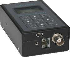
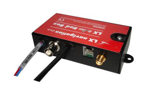
84 6.3.1 LX 7007 Compact configuration 5V, NMEA plus Flarm 84

85 7 Appendix 85
LX5000 V Variometer and GPS-Navigation System. Pilot's manual
 LX5000 V 11.0 Variometer and GPS-Navigation System Pilot's manual 1 Contents 1 CONTENTS...1 2 GENERAL...3 2.1 TECHNICAL DATA...3 2.2 ROTARY SWITCHES AND KEYS (BUTTONS)...3 2.2.1 ON/START button - Switching
LX Compass module 3 Electronic compass device User manual
 LX Compass module 3 Electronic compass device User manual LX navigation d.o.o., Tkalska 10 SLO 3000 Celje, tel: + 386 3 490 46 70, fax: + 386 3 490 46 71 info@lxnavigation.si, http://www.lxnavigation.com
Multifunction Altimeter/Variometer AV1
 Multifunction Altimeter/Variometer AV1 Revision#3.0, 21/11/2014 For firmware version 2.2 Page intentionally left blank SECTIONS MECHANICAL INSTALLATION ELECTRICAL INSTALLATION USE OF THE INSTRUMENT INSTRUMENT
CONSOLE-320 ENGLISH. 230A: CONSOLE-320 with cable data output Item 230B: CONSOLE-320 with cable + wireless radio data output
 CONSOLE-320 Item 230A: CONSOLE-320 with cable data output Item 230B: CONSOLE-320 with cable + wireless radio data output Table of contents 1. INTRODUCTION...2 1.1 Power supply...2 1.2 Connections...2 1.3
FireHawk M7 Interface Module Software Instructions OPERATION AND INSTRUCTIONS
 FireHawk M7 Interface Module Software Instructions OPERATION AND INSTRUCTIONS WARNING THE WARRANTIES MADE BY MSA WITH RESPECT TO THE PRODUCT ARE VOIDED IF THE PRODUCT IS NOT USED AND MAINTAINED IN ACCORDANCE
PART 5 - OPTIONS CONTENTS 5.1 SYSTEM EXPANSION 5-3
 PART 5 - OPTIONS CONTENTS Para Page 5.1 SYSTEM EXPANSION 5-3 5.2 SENSORS 5-3 5.2.1 Trim Angle Sensor 5-3 5.2.2 Mast Rotation Sensor 5-3 5.2.3 Heel Angle Sensor 5-3 5.2.4 Barometric Pressure Sensor 5-3
TECNAUTIC_GmbH. Display Functions with the PB100/200 connected: -- GND Speed -- GND Course -- Heading (Gyro option is recommended) 2 m
 2 m") PB100/200 Sonic Wind Wind, GPS, Compass Display Config: SE=12 di=00 df=20,91,30,34,(61) 35,36,81 Gr=01 n0=00 n1=07 n2=07**) n3=00 Display Functions with the PB100/200 connected: -- Apparent Wind -- True
PB100/200 Sonic Wind Wind, GPS, Compass Display Config: SE=12 di=00 df=20,91,30,34,(61) 35,36,81 Gr=01 n0=00 n1=07 n2=07**) n3=00 Display Functions with the PB100/200 connected: -- Apparent Wind -- True
REASONS FOR THE DEVELOPMENT
 7 Series 7 Series +24VDC VDC OUTPUT MICROPROCESS. E P IN EXH OUT 7 Series 7 ø,8 8 7 Series 9 5 8 9 7 Series Display features The proportional regulator has a 3 /2 digit display and a three-pushbutton
ASX-1. Introduction. 1 Features. Encoding aviation altimeter with serial output and airspeed Indicator (ASI) Operating Manual English 1.
 Operating Manual English 1.") ASX-1 Encoding aviation altimeter with serial output and airspeed Indicator (ASI) Operating Manual English 1.06 Introduction The ASX-1 altimeter/airspeed combo is a 2 1/4 instrument based on a precision
ASX-1 Encoding aviation altimeter with serial output and airspeed Indicator (ASI) Operating Manual English 1.06 Introduction The ASX-1 altimeter/airspeed combo is a 2 1/4 instrument based on a precision
S-TEC. Pilot s Operating Handbook
 S-TEC Pilot s Operating Handbook List of Effective Pages * Asterisk indicates pages changed, added, or deleted by current revision. Retain this record in front of handbook. Upon receipt of a Record of
Scoreboard Operator s Instructions MPC Control
 Scoreboard Operator s Instructions MPC Control Some features on the keyboard overlay may not be included on the particular model being operated. Since 1934 Retain this manual in your permanent files 1/21/2011
Revision Number Revision Date Insertion Date/Initials 1 st Ed. Oct 26, 00 2nd Ed. Jan 15, 08
 List of Effective Pages * Asterisk indicates pages changed, added, or deleted by current revision. Retain this record in front of handbook. Upon receipt of a Record of Revisions revision, insert changes
INSTALLATION INSTRUCTIONS AND REFERENCE HANDBOOK
 INSTALLATION INSTRUCTIONS AND REFERENCE HANDBOOK APPLICATION NOTES WIND MEASURING SYSTEMS Document no.: 4189340577BC SW version AGC 3.4X0.X0 or later and AGC 4.00.0 or later Document no.: 4189350050A Table
Instruction Manual Dräger MSI P7 and MSI P7 plus
 Dräger MSI GmbH Rohrstraße 32 58093 Hagen Tel.: +49-2331 / 9584-0 Fax: +49-2331 / 9584-29 e-mail: info@draeger-msi.de D 923; Edition 2011-01-01 Content 1. General Hints Page 4 2. The Instrument 2.1 Front
Pneumatic high-pressure controller Model CPC7000
 Calibration technology Pneumatic high-pressure controller Model CPC7000 WIKA data sheet CT 27.63 Applications Healthcare and avionics industry Industry (laboratory, workshop and production) Transmitter
ECHO MANUAL WARNING. L B A ltim e te rs. ECHO is a trademark of LB Altimeters, Denmark
 ECHO MANUAL L B A ltim e te rs ECHO is a trademark of LB Altimeters, Denmark LB Altimeters operates a policy of continuous development Therefore, we reserve the right to make changes and improvements to
Altimeter and Compass Watch Instruction Manual
 Altimeter and Compass Watch Instruction Manual Overview Figure 1 LCD display description Features Hour, minute, second, year, Auto calendar 12/24 hour format display month, day, day of week Daily alarm
SCIENTIFIC DATA SYSTEMS, INC. Depth Tension Line Speed Panel. DTLS Manual
 SCIENTIFIC DATA SYSTEMS, INC. Depth Tension Line Speed Panel DTLS Manual This document contains proprietary information. Copyright 2015 Scientific Data Systems, Inc. All rights reserved. 1 Depth Tension
DRAFT RULE TEXT version 4 30 Dec 2018
 DRAFT RULE TEXT version 4 30 Dec 2018 This document contains draft text of contest rules changes recommended by the SSA Rules Committee for implementation in 2019, as the result of discussions at the annual
OxyScan Graphic. Operating Instructions. UMS Micro-oxygen sensor 501. Microprocessor instrument
 OxyScan Graphic Operating Instructions UMS Micro-oxygen sensor 501 Microprocessor instrument Introduction Thank you for choosing the UMS Micro Oxygen Sensor 501 - a highly advanced product! Please read
Operating instructions Electrical switching facility pco
 Operating instructions Electrical switching facility pco from software version V1.33 on TABLE OF CONTENTS 1. Before you start... 4 1.1 Brief description... 4 1.2 Using this manual... 4 2. pco integrated
Ultra EFIS Update Software version 5.6 and Firmware version 3.15
 Ultra EFIS Update Software version 5.6 and Firmware version 3.15 User and Installation Manual Your journey, Our technology INDEX AvMap Ultra EFIS 1. Overview 4 2. Installation 5 2.1 Location 5 2.2 Mechanical
WARNING! FAILURE TO FOLLOW ALL WARNINGS, INSTRUCTIONS, AND REQUIRED PROCEDURES MAY RESULT IN SERIOUS INJURY AND DEATH.
 PROTRACK II Manual Every technical device can fail. So everything imaginable can happen with the PROTRACK II, including, but not limited to: displaying a status which is not true, failing to function,
303 Navigation Display Manual 302 DDV Version NAV Version Firmware by Phil Schlosser; text by Dave Ellis
 303 Navigation Display Manual 302 DDV Version 2.6 303-NAV Version 0.0.2 Firmware by Phil Schlosser; text by Dave Ellis 302 DDV (Actual Size) 303-NAV (Actual Size) Warranty All Cambridge Aero Instruments
Instruction Manual. BZ7002 Calibration Software BE
 Instruction Manual BZ7002 Calibration Software BE6034-12 Index _ Index Index... 2 Chapter 1 BZ7002 Calibration Software... 4 1. Introduction... 5 Chapter 2 Installation of the BZ7002... 6 2. Installation
HyperSecureLink V6.0x User Guide
 HyperSecureLink V6.0x User Guide Note: This software works with the LS-30 Version (06.0x or later) 1, Hardware Installation: 1-1, Connection Diagram for USB or RS-232 Computer Interface To LS-30 CM1 To
IBU3 Manual Addendum 1
 This addendum covers the follow items. Connection of airsoft micro switch Connection of Taigen airsoft recoil units Selecting airsoft mode Settings for clutch style gearboxes Motor enable selection Confirmation
ACV-10 Automatic Control Valve
 ACV-10 Automatic Control Valve Installation, Operation & Maintenance General: The Archer Instruments ACV-10 is a precision automatic feed rate control valve for use in vacuum systems feeding Chlorine,
Remote Control Bait Boat
 CARPIO 2.0 User Manual All pictures shown are for illustration purpose only. Actual product may vary due to product enhancement Remote Control Bait Boat (Smart Remote Control at 868 MHz) 1 Table of Contents
ECL Comfort 110, application 131 (valid as of software version 2.00)
") Operating Guide ECL Comfort 110, application 131 (valid as of software version 2.00) English version www.danfoss.com How to navigate? Adjust temperatures and values. Switch between menu lines. Select /
Operating Guide ECL Comfort 110, application 131 (valid as of software version 2.00) English version www.danfoss.com How to navigate? Adjust temperatures and values. Switch between menu lines. Select /
ZANDER SR 940. Operating Manual
 Version 1/01 ZANDER SR 940 Operating Manual Content: 1. Toggles and switches 2 2. GPS flight page 3 3. Flight page without GPS 5 4. Info lines 6 5. Organisation of pages 7 6. Text pages 8 7. Configuration
OPERATION INSTRUCTIONS
 TAS 1000 OPERATION INSTRUCTIONS DOCUMENT 1000-401 DATE: April 29/2011 REV. D PLEASE READ INSTRUCTIONS COMPLETELY BEFORE PROCEEDING WITH INSTALLATION Instrument Corporation P.O. Box 122 Fort Erie, Ontario
STAND alone & p.c. VERSION
 STAND alone & p.c. VERSION ECONOMY TRACK SYSTEMS 1/4 & 1/8 Mile Asphalt Track Dirt / Sand Track Mud Track Snowmobile Track R/C Car Track Custom Track Systems Timing to.001 Accuracy Time Slip Printer Optional
FAI Sporting Code. UAV Class U. Section 12 Unmanned Aerial Vehicles Edition. Effective 1st January 2018
 FAI Sporting Code Section 12 Unmanned Aerial Vehicles UAV Class U 2018 Edition Effective 1st January 2018 Section 12 and General Section combined make up the complete Sporting Code for UAV FEDERATION AERONAUTIQUE
OPERATION AND INSTALLATION MANUAL
 AP46 Autopilot OPERATION AND INSTALLATION MANUAL www.tmq.com.au TMQ AP46 Autopilot Page 1 of 34 Ver1.0 07/03/2007 This page is Blank TMQ AP46 Autopilot Page 2 of 34 Ver1.0 07/03/2007 WARNING!...4 INTRODUCTION...5
DBI version 002 User Manual US version Free Balloon Flight Instrument
 DBI version 002 User Manual US version Free Balloon Flight Instrument DBI 002 User Manual issue C7, 2005-05-25 Page 1/29 Safety The manufacturer has designed this instrument to be safe when operated. Do
Auriol LCD sports watch with altimeter and compass
 Instruction manual Safety notes This electronic appliance must be protected from water* and other hazards. It is not a toy and children should not use it unsupervised. * Splash proof if worn on wrist.
Hydro-Control V User Guide
 Hydro-Control V User Guide Hydronix Part no: HD0193 Version 2.3.0 Revision date: July 2006 1 COPYRIGHT Neither the whole or any part of the information contained in nor the product described in this documentation
How to make my Air Glide S work properly
 How to make my Air Glide S work properly Originally written by Horst Rupp. Many thanks to Richard Frawley who edited and retranslated this article into proper English. 2014/11/21. The basic prerequisite
SHIMADZU LC-10/20 PUMP
 SHIMADZU LC-10/20 PUMP Clarity Control Module ENG Code/Rev.: M091/70C Date: 24.10.2017 Phone: +420 251 013 400 DataApex Ltd. Fax: +420 251 013 401 Petrzilkova 2583/13 clarity@dataapex.com 158 00 Prague
The Military CYPRES Quick Guide For Operators
 The Military CYPRES Quick Guide For Operators The military CYPRES is available in the following standard models: All models can be adapted with a one or two-pin cutter. 1000/35 A 1500/35 A 1000/35 indicates
DT 630 ALTIMETER, BAROMETER AND COMPASS WATCH OPERATING INSTRUSTIONS
 DT 630 ALTIMETER, BAROMETER AND COMPASS WATCH OPERATING INSTRUSTIONS Overview:--- Positive or Negative Icon Barometric Trend Indicator SELECT Low Battery Indicator AM/FM Indicator Daily Alarm Indicator
APPLICATION NOTES. WIND MEASURING SYSTEMS using XDi-N indicators. Document no.: B
 APPLICATION NOTES WIND MEASURING SYSTEMS using XDi-N indicators Document no.: 4189350080B Table of contents GENERAL INFORMATION... 4 WARNINGS, LEGAL INFORMATION AND SAFETY... 4 LEGAL INFORMATION AND DISCLAIMER...
Manual Weighingblock VB2 series and Uniscale
 Manual Weighingblock VB2 series and Uniscale Note: At page 8 in this manual you will find a short form instruction. Normally the only instruction shipped together with the Scale. Overview different ranges.
THE SOUNDBEAM 2 HANDBOOK PART 2 STEP BY STEP
 THE SOUNDBEAM 2 HANDBOOK PART 2 STEP BY STEP THE SOUNDBEAM PROJECT JANUARY 2002 CONTENTS 1. SET-UPS p. 5 1.1. To Select a Set-up p. 6 1.2. To Save a Set-up p. 8 1.3. To Copy the Modified Settings of a
Pegas 4000 MF Gas Mixer InstructionManual Columbus Instruments
 Pegas 4000 MF Gas Mixer InstructionManual Contents I Table of Contents Foreword Part I Introduction 1 2 1 System overview... 2 2 Specifications... 3 Part II Installation 4 1 Rear panel connections...
SENSUS PRO MANAGER (for SENSUS or SENSUS PRO devices) User s Guide -- Windows. Version 2.0 Published October 17, ReefNet Inc.
 User s Guide -- Windows. Version 2.0 Published October 17, ReefNet Inc.") SENSUS PRO MANAGER (for SENSUS or SENSUS PRO devices) User s Guide -- Windows Version 2.0 Published October 17, 2002 2002 ReefNet Inc. 1.0 Introduction The SENSUS PRO data recorder captures the time, depth,
SENSUS PRO MANAGER (for SENSUS or SENSUS PRO devices) User s Guide -- Windows Version 2.0 Published October 17, 2002 2002 ReefNet Inc. 1.0 Introduction The SENSUS PRO data recorder captures the time, depth,
Figure 7-1 Waypoint Info Page
 7 WAYPOINT INFO The Waypoint Info function allows you to view information about the selected waypoint. The Waypoint Info page can be reached from the Home page, selected from a flight plan, or selected
Operating Manual. SUPREMA Calibration. Software for Fire and Gas Warning Units. Order No.: /01. MSAsafety.com
 Operating Manual Software for Fire and Gas Warning Units Order No.: 10154656/01 MSAsafety.com MSA Europe GmbH Schlüsselstrasse 12 8645 Rapperswil-Jona Switzerland info.ch@msasafety.com www.msasafety.com
Pneumatic high-pressure controller Model CPC7000
 Calibration technology Pneumatic high-pressure controller Model CPC7000 WIKA data sheet CT 27.63 Applications Automotive and avionics industry Industry (laboratory, workshop and production) Transmitter
RM-80 respiration monitor
 RM-80 respiration monitor User Manual September 18, 2015 0025-003M 950 North Hague Avenue Columbus, Ohio 43204-2121 USA Sales: sales@colinst.com Service: service@colinst.com Phone: (614) 276-0861 Fax:
ALT-1. Introduction. Precision Encoding Altimeter and Vertical speed indicator (VSI) Operating Manual English 1.09
 Operating Manual English 1.09") ALT-1 Precision Encoding Altimeter and Vertical speed indicator (VSI) Operating Manual English 1.09 Introduction The ALT-1 is a 2 1/4 instrument that contains a precision encoding altimeter and a wide
ALT-1 Precision Encoding Altimeter and Vertical speed indicator (VSI) Operating Manual English 1.09 Introduction The ALT-1 is a 2 1/4 instrument that contains a precision encoding altimeter and a wide
2013 CIVL PLENARY ANNEX 24B SOFTWARE PROPOSALS
 2013 CIVL PLENARY ANNEX 24B SOFTWARE PROPOSALS In conjunction with the Hang Gliding, Paragliding and Aerobatic Subcommittees 1. Speed rank used to calculate time validity At the 2008 CIVL plenary, the
Safety Manual. Process pressure transmitter IPT-1* 4 20 ma/hart. Process pressure transmitter IPT-1*
 Safety Manual Process pressure transmitter IPT-1* 4 20 ma/hart Process pressure transmitter IPT-1* Contents Contents 1 Functional safety 1.1 General information... 3 1.2 Planning... 4 1.3 Instrument parameter
2. USER INSTRUCTION. Table of contents: Pg.1/14 N:\FAP-2000: LWP
 Pg.1/14 2. USER INSTRUCTION. Table of contents: 2.1 SHORT PANEL DESCRIPTION...... Pg.2 2.2 AUTOPILOT TAKE-OVER & MODE SELECTION....... Pg.3 2.3 AUTOPILOT FUNCTIONS....... Pg.3 2.4 THE SPECIAL FUNCTION
VISO Manual. LARSEN & BRUSGAARD Mosevej Kirke Hyllinge, Denmark Phone: Fax:
 VISO Manual LARSEN & BRUSGAARD Mosevej 3 4070 Kirke Hyllinge, Denmark Phone: +45 4648 2480 Fax: +45 4648 2490 E-mail: L-and-B@L-and-B.dk WARNING! FAILURE TO FOLLOW ALL WARNINGS, INSTRUCTIONS, AND REQUIRED
iregatta User Manual
 iregatta User Manual iregatta User Manual This manual may not always be up to date with the latest version of iregatta available in Apples App Store, as minor additions or bug fixes may be published without
Cambridge Aero Instruments L-NAV Glide Computer Version 5.8
 Cambridge Aero Instruments L-NAV Glide Computer Version 5.8 March, 2000 Netto averager (Configurable option) Speed command bar graph Distance to the goal Instantaneous wind component in the direction of
The HumiSys. RH Generator. Operation. Applications. Designed, built, and supported by InstruQuest Inc.
 The HumiSys RH Generator Designed, built, and supported by InstruQuest Inc. Versatile Relative Humidity Generation and Multi-Sensor System The new HumiSys with single or dual RH probes capabilities is
SonoMeter 30 Energy Meters
 Data Sheet SonoMeter 30 Energy Meters Description The Danfoss SonoMeter 30 is a range of ultrasonic, compact energy meters intended for measuring energy consumption in heating and cooling applications
HumiSys HF High Flow RH Generator
 HumiSys HF High Flow RH Generator Designed, built, and supported by InstruQuest Inc. Versatile Relative Humidity Generation and Multi-Sensor System The HumiSys HF is a high flow version of the previously
Race Screen: Figure 2: Race Screen. Figure 3: Race Screen with Top Bulb Lock
 Eliminator Competition Stand Alone Mode - Instruction Manual Main Menu: After startup, the Eliminator Competition will enter the Main Menu. Press the right/left arrow buttons to move through the menu.
RESOLUTION MSC.94(72) (adopted on 22 May 2000) PERFORMANCE STANDARDS FOR NIGHT VISION EQUIPMENT FOR HIGH-SPEED CRAFT (HSC)
 (adopted on 22 May 2000) PERFORMANCE STANDARDS FOR NIGHT VISION EQUIPMENT FOR HIGH-SPEED CRAFT (HSC)") MSC 72/23/Add.1 RESOLUTION MSC.94(72) EQUIPMENT FOR HIGH-SPEED CRAFT (HSC) THE MARITIME SAFETY COMMITTEE, RECALLING Article 28(b) of the Convention on the International Maritime Organization concerning
MSC 72/23/Add.1 RESOLUTION MSC.94(72) EQUIPMENT FOR HIGH-SPEED CRAFT (HSC) THE MARITIME SAFETY COMMITTEE, RECALLING Article 28(b) of the Convention on the International Maritime Organization concerning
PILOT WIZZ - THE PILOTS COMPANION PilotWiz 1.0.5
 FAQ/NOTES All configuration is saved when the program is closed properly - so if you've enter lots of configuration then close the program and restart to ensure it is all saved. We would not want a flat
SIDRA INTERSECTION 6.1 UPDATE HISTORY
 Akcelik & Associates Pty Ltd PO Box 1075G, Greythorn, Vic 3104 AUSTRALIA ABN 79 088 889 687 For all technical support, sales support and general enquiries: support.sidrasolutions.com SIDRA INTERSECTION
TL-3524 USER`S MANUAL
 TL-3524 USER`S MANUAL TL TL Airport, Building 125, Hradec Kralove 503 41, Czech Republic Copyright 2003, TL Non TSO approved Copyright 2003-2006 TL All Rights Reserved Except as expressly provided below,
Temperature Controller CC24-7 ULTRA USER S MANUAL Legion Dr. Mason, MI USA October 2010 Ph. (517) Fax (517)
 Fax (517)") Temperature Controller USER S MANUAL Aerotech, Inc. FORM: QM1387 4215 Legion Dr. Mason, MI 48854-1036 USA October 2010 Ph. (517) 676-7070 Fax (517) 676-7078 FOR CUSTOMER USE Enter the serial number located
Temperature Controller USER S MANUAL Aerotech, Inc. FORM: QM1387 4215 Legion Dr. Mason, MI 48854-1036 USA October 2010 Ph. (517) 676-7070 Fax (517) 676-7078 FOR CUSTOMER USE Enter the serial number located
Safety Manual VEGAVIB series 60
 Safety Manual VEGAVIB series 60 NAMUR Document ID: 32005 Contents Contents 1 Functional safety... 3 1.1 General information... 3 1.2 Planning... 4 1.3 Adjustment instructions... 6 1.4 Setup... 6 1.5 Reaction
Specifications and information are subject to change without notice. Up-to-date address information is available on our website.
 www.smar.com Specifications and information are subject to change without notice. Up-to-date address information is available on our website. web: www.smar.com/contactus.asp LD302 - AssetView HMI LD302
SECTION 6-16 FLIGHT INSTRUMENTS
 SECTION 6-16 SYSTEMS DESCRIPTION Index Page Pitot-Static System... 6-16-2 Airspeed Indicator... 6-16-4 Vertical Speed Indicator... 6-16-4 Instantaneous Vertical Speed Indicator IVSI (Optional)... 6-16-5
FLIGHT CREW TRAINING NOTICE
 SAFETY REGULATION GROUP FLIGHT CREW TRAINING NOTICE 06/2009 Applicability: RETRE, TRIE, TRE, SFE, TRI, SFI Effective: Immediate AIRBORNE COLLISION AVOIDANCE SYSTEM (ACAS) TRAINING 1 The purpose of this
INTRODUCTION TO NETWORK WIND 3 MOUNTING THE UNIT 14 SELECTING THE DISPLAY MODE 5 ABBREVIATIONS AND DEFINITIONS 17
 CONTENTS CONTENTS 1 INSTALLATION 14 GENERAL INTRODUCTION TO B&G NETWORK 2 SITING THE UNIT 14 INTRODUCTION TO NETWORK WIND 3 MOUNTING THE UNIT 14 EXAMPLE SYSTEMS USING NETWORK WIND 4 SPECIFICATION 16 SELECTING
FAI Sporting Code. UAV Class U. Section 12 Unmanned Aerial Vehicles Edition. Effective 1st January 2019
 FAI Sporting Code Section 12 Unmanned Aerial Vehicles UAV Class U 2019 Edition Effective 1st January 2019 Section 12 and General Section combined make up the complete Sporting Code for UAV FEDERATION AERONAUTIQUE
v2.3 USER MANUAL
 v2.3 USER MANUAL www.foresightsports.com Table of Contents 03 04 05 09 12 17 20 21 Activation Getting Started Play Compete Improve Settings Update Manager Glossary 04 11 05 12 03 Activation FSX Activation
WIND CLIPPER KTS ILLUM SCALE INC DEC CLIPPER WIND SYSTEM
 CLIPPER WIND KTS ILLUM SCALE DEC INC CLIPPER WIND SYSTEM TABLE OF CONTENTS INTRODUCTION PRE-TEST OF INSTRUMENT INSTALLING THE MASTHEAD SENSOR UNIT INSTALLING THE DISPLAY NORMAL OPERATION CHANGING THE
Descent Planning with a Mechanical E6-B Flight Computer
 Descent Planning with a Mechanical E6-B Flight Computer Most pilots are familiar with an E6-B mechanical flight computer as it is considered to be an integral part of a new pilot s training for use with
Walk-O-Meter User Manual
 Walk-O-Meter User Manual For BlackBerry Z10 and Q10 Version 2 Date 2013-09-26 1 Thank you for purchasing the Walk-O-Meter App from Cellimagine LLC. Walk-O-Meter pedometer app for your Z10 is the ultimate
The ASV-2 is a 3 1/8 sunlight readable encoding altimeter, airspeed and wide range vertical speed indicator.
 Blaze ASV-2 Altimeter, Airspeed (ASI) and Vertical Speed Indicator (VSI) Operating Manual English 1.00 Introduction The ASV-2 is a 3 1/8 sunlight readable encoding altimeter, airspeed and wide range vertical
A4s Operation Manual
 A4s Operation Manual Safety Instruction Please read this manual carefully, also with related manual for the machinery before use the controller. For installing and operating the controller properly and
FRDS GEN II SIMULATOR WORKBOOK
 FRDS GEN II SIMULATOR WORKBOOK Trotter Control Inc 2015 Document# Revision Revised 9001-0038 FRDS GEN II Simulator Workbook E 02/15/2015 by DC FRDS GEN II Simulator Workbook This workbook is a follow-on
628 Differential Pressure Decay Leak Tester
 628 Differential Pressure Decay Leak Tester The 628 puts Uson s industry leading differential pressure decay sensitivity in your hands and in your budget with no compromise in quality, reliability, and
AIR NAVIGATION. Key Revision. Press F5 to start.
 AIR NAVIGATION Key Revision Press F5 to start. This presentation may be used either as a revision aid or as a self-test program. Revision Self-test Instructions This presentation may be used either as
AN-140. Protege WX SALLIS Integration Application Note
 AN-140 Protege WX SALLIS Integration Application Note The specifications and descriptions of products and services contained in this document were correct at the time of printing. Integrated Control Technology
LED CONVERSION BOARD - YAKUZA SERIES EGO/GEO
 LED CONVERSION BOARD - YAKUZA SERIES EGO/GEO The LED conversion board replaces the OLED screen mini-board on your Yakuza Series board. Combined with new firmware, your board will function similarly to
APA software instruction manual
 1. Starting the program In order to start the control software for the APA device press APAxx shortcut located on the desktop of the supplied computer. XX corresponds to the current software version. When
USER GUIDE USER GUIDE
 1 TABLE OF CONTENTS GETTING STARTED 2 Included in the box 2 Compatible smartphones 2 Accessories: 2 Download Mobitee and PIQ application 2 GET STARTED WITH MOBITEE AND PIQ 3 Create your Account and Login
TOP BLEED Position for SeaTalk 2 colour logo ST 30. COMPASS Operation and Installation
 Distributed by Any reference to Raytheon or RTN in this manual should be interpreted as Raymarine. The names Raytheon and RTN are owned by the Raytheon Company. TOP BLEED Position for SeaTalk 2 colour
Digitool Instruments AB DBI3 US User Manual Free Balloon Flight Instrument
 Digitool Instruments AB DBI3 US User Manual Free Balloon Flight Instrument Not Used DBI3 User Manual, Rev C, 9 Nov 2017 Page 2 of 29 Safety Digitool AB has designed this flight instrument to enable the
2. At a ground speed of 184 knots, what will be the time required to cover 288 nautical miles? a. 86 minutes b. 90 minutes c. 94 minutes d.
 1. What is the equivalent distance of 700 statute miles in nautical miles? a. 608 b. 810 c. 722 d. 934 2. At a ground speed of 184 knots, what will be the time required to cover 288 nautical miles? a.
Technology. In the My Files [My Files] submenu you can store all the programs that you have made on the NXT or downloaded from your computer.
![Technology. In the My Files [My Files] submenu you can store all the programs that you have made on the NXT or downloaded from your computer.](/thumbs/74/70002303.jpg "Technology. In the My Files [My Files] submenu you can store all the programs that you have made on the NXT or downloaded from your computer.") NXT Main Menu My Files Files are automatically placed into the appropriate folders. When you download a program using a Sound file to the NXT, the program will be placed under Software files while the
NXT Main Menu My Files Files are automatically placed into the appropriate folders. When you download a program using a Sound file to the NXT, the program will be placed under Software files while the
GNX 20/21. Owner s Manual
 GNX 20/21 Owner s Manual Table of Contents Introduction...1 Device Overview... 1 Using the Race Timer... 1 Profiles... 1 Selecting a Profile... 1 Restoring Profiles to their Default Settings... 1 Instrument
MANUAL. P C - C E N T E R Version Copyright by Dinand van het Reve CONTENTS
 P C - C E N T E R Version 4.00 Copyright 1995-2004 by Dinand van het Reve CONTENTS 1. Introduction 2. Installing PC-CENTER 3. Licence 4. Using PC-CENTER 5. Description of 'Small Windows' 6. Main Menu Description
5 Function Indicator. Outside Air Temperature (C) Outside Air Temperature (F) Pressure Altitude Density Altitude Aircraft Voltage STD TEMP SL 15000
 Outside Air Temperature (F) Pressure Altitude Density Altitude Aircraft Voltage STD TEMP SL 15000") 5 Function Indicator +20 +40-5000 STD TEMP SL 15000 Outside Air Temperature (C) Outside Air Temperature (F) Pressure Altitude Density Altitude Aircraft Voltage 427 HILLCREST WAY REDWOOD CITY, CA 94062
5 Function Indicator +20 +40-5000 STD TEMP SL 15000 Outside Air Temperature (C) Outside Air Temperature (F) Pressure Altitude Density Altitude Aircraft Voltage 427 HILLCREST WAY REDWOOD CITY, CA 94062
nvisti Kestrel Companion Pro For Android
 nvisti Kestrel Companion Pro For Android The nvisti Kestrel Companion App is the most versatile, accurate and user friendly dual purpose app available. This app allows for both remote viewing for firing
The ASV-1 is a 2 1/4 sunlight readable encoding altimeter, airspeed and wide range vertical speed indicator.
 Vega ASV- Altimeter, Airspeed (ASI) and Vertical Speed Indicator (VSI) Operating Manual English. Introduction The ASV- is a 2 /4 sunlight readable encoding altimeter, airspeed and wide range vertical speed
P/N 135A EASA Approved: June 23, 2011 Section 9 Initial Release Page 1 of 22
 EASA APPROVED AIRPLANE FLIGHT MANUAL SUPPLEMENT FOR S-TEC SYSTEM 30 AUTOPILOT INTEGRATED IN THE LIBERTY XL2 SERIES AIRCRAFT Serial No: Registration No: When installing the S-TEC System 30 Autopilot Integrated
Precision pressure sensor Basic version Model CPT6020
 Calibration Precision pressure sensor Basic version Model CPT6020 WIKA data sheet CT 25.13 Applications Calibration technology High-accuracy pressure monitoring Pressure sensing in critical applications
Roller AC Servo System
 Safely Instruction Roller AC Servo System HMI-15 User Manual Please read this manual carefully, also with related manual for the machinery before use the controller. For installing and operating the controller
Copyright 2004 by the Thomas G. Faria Corporation, Uncasville CT No part of this publication may by reproduced in any form, in an electronic
 Copyright 2004 by the Thomas G. Faria Corporation, Uncasville CT No part of this publication may by reproduced in any form, in an electronic retrieval system or otherwise, without the prior written permission
WF STEUERUNGSTECHNIK GMBH. INFORMATION and TECNICAL DESCRIPTION
 1 INFORMATION and TECNICAL DESCRIPTION 14 2 AIRLEADER Professional Compressor Management + Compressed Air Visualisation + Alarm Service Management + AIRLEADER - has been the effective answer for compressed