NATURAL GAS MAINTENANCE. Part 192 Subpart "M"
|
|
|
- Brook O’Brien’
- 6 years ago
- Views:
Transcription

1 NATURAL GAS MAINTENANCE Part 192 Subpart "M"

2 CONTACT INFORMATION Pamela West Pipeline Safety Specialist U.S. Department of Transportation PHMSA Inspector Training and Qualifications Main: (405) My Office: (405)

3 GENERAL Each segment must be maintained in accordance with this Subpart. Each unsafe segment must be repaired, replaced or removed. Hazardous leaks must be repaired promptly.
 Must look for; Leaks, construction activity, and")
4 TRANSMISSION LINES: PATROLLING (a) Must look for; Leaks, construction activity, and other factors affecting safety.
 When establishing frequencies, must consider; Operating pressures, Class")
5 TRANSMISSION LINES: PATROLLING (b) When establishing frequencies, must consider; Operating pressures, Class location, Terrain, Weather, Other relevant factors.
 Maximum interval between patrols: Class 1,2 Hwy & RR All Other Locations At least twice each calendar year,")
6 TRANSMISSION LINES: PATROLLING (c) Maximum interval between patrols: Class 1,2 Hwy & RR All Other Locations At least twice each calendar year, not to exceed 7 1/2 months. At least once each calendar year, not to exceed15 months.
7 TRANSMISSION LINES: PATROLLING (c) Maximum interval between patrols: Class 3 Hwy & RR All Other Locations Class 4 Hwy & RR All Other Locations At least four times each calendar year, not to exceed 4 ½ months. At least twice each calendar year, not to exceed 7 ½ months. At least four times each calendar year, not to exceed 4 ½ months. At least four times each calendar year, not to exceed 4 ½ months.
8 TRANSMISSION LINES: PATROLLING


9 TRANSMISSION LINES LEAKAGE SURVEYS Transmission lines must be leak surveyed once each calendar year, not to exceed fifteen months. Except class 3 & 4 areas transporting un-odorized gas, must use leak detection equipment. Class 3 = Twice each calendar year not to exceed 7 ½ months. Class 4 = Four times each calendar year not to exceed 4 ½ months.


10 LINE MARKERS FOR MAINS AND TRANSMISSION LINES (a) Marker must be Placed & Maintained as close as practical; At each crossing of public road & railroad; and

11 (a) LINE MARKERS FOR MAINS AND TRANSMISSION LINES Wherever necessary to identify the location of the transmission line or main to reduce possibility of damage or interference.

12 (b) LINE MARKERS FOR MAINS AND TRANSMISSION LINES Exceptions: Mains and transmission lines located offshore, at crossings of or under waterways or bodies of water. Mains in class 3 & 4 locations where a damage prevention program is in effect;
 Exceptions continued; Transmission lines in class 3 & 4 areas where")
13 LINE MARKERS FOR MAINS AND TRANSMISSION LINES (b) Exceptions continued; Transmission lines in class 3 & 4 areas where placement of a line marker is impractical.
 Pipelines Above ground Markers must be installed and maintained in")
14 LINE MARKERS FOR MAINS AND TRANSMISSION LINES (c) Pipelines Above ground Markers must be installed and maintained in areas accessible to the public.
 Must Have the word Warning, Caution, or Danger Followed by")

15 LINE MARKERS FOR MAINS AND TRANSMISSION LINES (d) Must Have the word Warning, Caution, or Danger Followed by Gas (or name of gas) Pipeline Letters must be at least 1 high with ¼ stroke. Must have Operator name and 24 hr. phone number. TQ Pipeline Co

16 TRANSMISSION LINE RECORDKEEPING The date, location, and description of each repair to pipe or pipe-to-pipe connections must be retained for as long as the pipe remains in service.
17 TRANSMISSION LINE RECORDKEEPING Records for the following must be retained for 5 years or until the next survey, inspection, or test is completed, whichever is longer: Repairs to parts of the pipeline other than pipe Leakage Surveys Patrols Inspections & tests required by Subparts L & M

18 (a)(1) TRANSMISSION LINES: REPAIR PROCEDURES Immediate temporary measures to protect public when a line operating at 40% SMYS or greater has a leak, imperfection, or damage that impairs serviceability: and
19 TRANSMISSION LINES: REPAIR PROCEDURES (a)(2)(b) If it is not feasible to make permanent repairs at the time. An operator shall make permanent repairs as soon as feasible. Conditions covered by Subpart O, Gas IM, must be remediated as prescribed in (d) Welded patches are not allowed except as provided by (b)(3).
 Repaired by a method that reliable engineering tests and analyses show can permanently restore the serviceability of the")
20 (a) TRANSMISSION LINES: PERMANENT REPAIRS Imperfections or damage on a line operating at 40% SMYS must be: (1) Removed by cutting out and replacing a cylindrical piece of pipe; or (2) Repaired by a method that reliable engineering tests and analyses show can permanently restore the serviceability of the pipe.

21 (b) TRANSMISSION LINES: REPAIR PROCEDURES Operating pressure must be at a safe level during repair operations.
 Removing the leak by cutting out and replacing a cylindrical piece of pipe; or (b)")
22 TRANSMISSION LINES: REPAIR PROCEDURES (a) Removing the leak by cutting out and replacing a cylindrical piece of pipe; or (b) Repairing the leak by one of the following methods:
23 TRANSMISSION LINES: REPAIR PROCEDURES (b) (1) Install a full encirclement welded split sleeve of appropriate design, unless the transmission line is joined by mechanical couplings and operates at less than 40 percent of SMYS. (2) If the leak is due to a corrosion pit, install a properly designed bolt-on-leak clamp.

24 (b) TRANSMISSION LINES: REPAIR PROCEDURES (3) If the leak is due to a corrosion pit and on pipe of not more than 40,000 psi (267 Mpa) SMYS, fillet weld over the pitted area a steel plate patch with rounded corners, of the same or greater thickness than the pipe, and not more than one-half of the diameter of the pipe in size.


25 (b) TRANSMISSION LINES: REPAIR PROCEDURES (4) If the leak is on a submerged offshore pipeline or submerged pipeline in inland navigable waters, mechanically apply a full encirclement split sleeve of appropriate design.

26 (b) TRANSMISSION LINES: REPAIR PROCEDURES (5) Apply a method that reliable engineering tests and analyses show can permanently restore the serviceability of the pipe.


27 (a) TRANSMISSION LINES: TESTING OF REPAIRS Replacement pipe must be tested to the pressure required for a new line in the same location.

28 (b) TRANSMISSION LINES: TESTING OF REPAIRS Each repair made by welding must be examined in accordance with
29 DISTRIBUTION: PATROLLING The frequency of patrolling mains is determined by the severity of conditions which could cause a hazard to public safety. Areas subject to physical movement or external loading where failure could result must be patrolled at least: At least 4 times each calendar year not to exceed 4 ½ mo. in business districts. At least 2 times each calendar year not to exceed 7 ½ mo. outside business districts.
 Type and scope of leakage control program must be determined by local")
30 DISTRIBUTION LEAK SURVEYS (b) Type and scope of leakage control program must be determined by local conditions, but must meet the following minimums:

31 DISTRIBUTION LEAK SURVEYS (b)(1) Business Districts Once each calendar year not to exceed 15 months. Must check: Manholes Pavement & sidewalk cracks; and Other potential venting locations. Must use leak detection equipment.
(2) Outside of business district as frequent as necessary, but at least once")

32 DISTRIBUTION LEAK SURVEYS (b)(2) Outside of business district as frequent as necessary, but at least once every 5 calendar years at intervals not to exceed 63 months; or Pipe that is not cathodically protected and subject to (e) must be surveyed at least once every 3 calendar years at intervals not to exceed 39 months

33 TEST REQUIREMENTS FOR RE-INSTATING SERVICE LINES Each disconnected service must be tested in the same manner as a new service. Each temporarily disconnected service must be tested from the point of disconnection to the service line valve.
 Each pipeline abandoned in place must be; Disconnected from all")

34 ABANDONMENT (b) Each pipeline abandoned in place must be; Disconnected from all sources of gas, purged, and sealed. Offshore must be filled with water or inert materials and sealed at the ends. Purging is not required if the volume of gas is so small that it does not present a hazard.
35 ABANDONMENT (d)(e) When service to a customer is disconnected, the operator must do one of the following; Close and lock the valve. Install a mechanical device or fitting in the service line or meter to prevent the flow of gas. The customers piping must be physically disconnect from the gas supply and the ends sealed. If purged with air, insure a combustible mixture is not present after purging.

36 (f) ABANDONMENT Each abandoned vault must be filled with compacted materials.

37 (a) COMPRESSOR STATIONS: INSPECTION AND TESTING OF RELIEF DEVICES. Except for rupture discs, each pressure relieving device in a compressor station must be inspected and tested in accordance with and , and must be operated periodically to determine that it opens at the correct set pressure.
38 COMPRESSOR STATIONS: INSPECTION AND TESTING OF RELIEF DEVICES (b)(c) Any defective or inadequate equipment found must be promptly repaired or replaced. Each remote control shutdown device must be inspected and tested at least once each calendar year, at intervals not exceeding 15 months to determine that it functions properly.

39 COMPRESSOR STATIONS: STORAGE OF COMBUSTIBLE MATERIALS Flammable or combustible materials in quantities beyond those required for everyday use, must be stored a safe distance from the compressor building. Above ground oil or gasoline storage tanks must be protected in accordance with National Fire Protection Association Standard No. 30.
40 COMPRESSOR STATIONS: GAS DETECTION (a) Each compressor building in a compressor station must have a fixed gas detection and alarm system, unless the building is- Constructed so that at least 50 percent of it s upright side area is permanently open; or Located in an unattended field compressor station of 1,000 horsepower or less.
41 COMPRESSOR STATIONS: GAS DETECTION (b) Except when shutdown of the system is necessary for maintenance under paragraph (c), each gas detection and alarm system must- Continuously monitor the compressor building for a concentration of gas in air of not more than 25 percent of the lower explosive limit; and If that concentration of gas is detected, warn persons about to enter the building and persons inside the building of the danger.
42 (c) COMPRESSOR STATIONS: GAS DETECTION. Each gas detection and alarm system required by this section must be maintained to function properly. The maintenance must include performance tests.
43 PRESSURE LIMITING AND REGULATING STATIONS: INSPECTION AND TESTING (a) Each pressure limiting station, relief device (except rupture discs), and Pressure regulating station and its equipment must be inspected and tested at least once each calendar year at intervals not exceeding 15 months to determine that it is In good mechanical condition. Adequate from the standpoint of capacity and reliability of operation.
 Except as provided in paragraph (b), set to control or relieve at the correct pressure consistent with the pressure limits of 192.201(a).")
44 PRESSURE LIMITING AND REGULATING STATIONS: INSPECTION AND TESTING (a) Except as provided in paragraph (b), set to control or relieve at the correct pressure consistent with the pressure limits of (a). Properly installed and protected from dirt, liquids, or other conditions that might prevent proper operation.
45 PRESSURE LIMITING AND REGULATING STATIONS: INSPECTION AND TESTING (b) For steel pipelines whose MAOP is determined under (c), if the MAOP is 60 psi gage or more, the control or relief pressure limit is as follows: MAOP Hoop Stress Greater than 72% SMYS Less than 72% SMYS Unknown % SMYS Pressure Limit MAOP plus 4% MAOP plus 10% ( (a)(2)) Pressure that will prevent unsafe operation considering MAOP, operation, & Maint. History.
46 PRESSURE LIMITING AND REGULATING STATIONS: TELEMETERING OR RECORDING GAGES (a)(b) Each distribution system supplied by more than one district pressure regulating station must be equipped with telemetering or recording pressure gages to indicate the gas pressure in the district. On distribution systems supplied by a single pressure regulating station, the operator shall determine the necessity of telemetering or recording gages, considering the number of customers supplied, operating pressures, capacity of the installation, and other operating conditions.


47 PRESSURE LIMITING AND REGULATING STATIONS: TELEMETERING OR RECORDING GAGES (c) If there are indications of abnormally high- or lowpressure, the regulator and auxiliary equipment must be inspected and the necessary measures employed to correct any unsatisfactory operating conditions.
48 (a) PRESSURE LIMITING AND REGULATING STATIONS: CAPACITY OF RELIEF DEVICES Pressure relief devices at pressure limiting stations and pressure regulating stations must have sufficient capacity to protect the facilities to which they are connected. Except as provided in (b), the capacity must be consistent with the pressure limits of (a), and must be determined at least once each calendar year not to exceed 15 months, by testing the devices in place or by review and calculations.
49 (b)(c) PRESSURE LIMITING AND REGULATING STATIONS: CAPACITY OF RELIEF DEVICES If review and calculations are used, the calculated capacity must be compared with the rated or experimentally determined relieving capacity of the device for the conditions under which it operates. After the initial calculations, subsequent calculations need not be made if the annual review documents that parameters have not changed. If a relief device is of insufficient capacity, a new or additional device must be installed to provide the capacity required by paragraph (a) of this section.
50 (a) VALVE MAINTENANCE: TRANSMISSION LINES Each valve that might be required during an emergency must be inspected and partially operated at least once each calendar year not to exceed 15 months.

51 (b) VALVE MAINTENANCE: TRANSMISSION LINES Prompt remedial action is required to correct any valve found inoperable, unless an alternative valve is designated.

52 (a) VALVE MAINTENANCE: DISTRIBUTION SYSTEMS Each valve, necessary for safe operation of a distribution system, must be checked and serviced once each calendar year, not to exceed 15 months.
53 VALVE MAINTENANCE: DISTRIBUTION SYSTEMS (b) Each valve, necessary for safe operation of a distribution system, must be checked and serviced: At least once each calendar year not to exceed15 months. Prompt remedial action is required to correct any valve found inoperable, unless an alternative valve is designated.

54 (a) VAULT MAINTENANCE Vaults containing pressure regulating or limiting equipment, greater than 200 cubic ft. must be inspected each calendar year not to exceed 15 months for physical condition and ventilation.
(c)(d) If gas is detected, inspect for and repair leaks.")
55 VAULT MAINTENANCE (b)(c)(d) If gas is detected, inspect for and repair leaks. Inspect ventilating equipment. Inspect integrity of vault covers.

56 PREVENTION OF ACCIDENTAL IGNITION Each operator must minimize danger of accidental ignition. Remove ignition sources Provide fire extinguishers Post Warnings Don't weld around combustible mixtures.
57 CAST IRON: CAULKED BELL AND SPIGOT JOINTS (a) Each cast iron caulked bell and spigot joint that is subject to pressures of more than 25 psi gage must be sealed with: A mechanical leak clamp; or A material or device which: Does not reduce the flexibility of the joint; Permanently bonds, either chemically or mechanically, or both, with the bell and spigot metal surfaces or adjacent pipe metal surfaces; and,
58 CAST IRON: CAULKED BELL AND SPIGOT JOINTS (a)(b) Seals and bonds in a manner that meets the strength, environmental, and chemical compatibility requirements of (a) and (b) and Each cast iron caulked bell and spigot joint that is subject to pressures of 25 psi gage or less and is exposed for any reason must be sealed by a means other than caulking.
59 PROTECTING CAST IRON PIPELINES (a) When an operator has knowledge that the support for a segment of a buried cast-iron pipeline is disturbed: That segment of the pipeline must be protected, as necessary, against damage during the disturbance by: Vibrations from heavy construction equipment, trains, trucks, buses, or blasting; Impact forces by vehicles;
60 PROTECTING CAST IRON PIPELINES (a)(b) Earth movement; Apparent future excavations near the pipeline; or Other foreseeable outside forces which may subject that segment of the pipeline to bending stress. As soon as feasible, appropriate steps must be taken to provide permanent protection for the disturbed segment from damage that might result from external loads, including compliance with applicable requirements of (a), , and (b)-(d).
61 INFORMATION WEBSITES PHMSA Training and Qualification PHMSA Pipeline Safety Regulations
New Hampshire Public Utilities Commission CFR 49 Part 192 Regulations. MINIMUM Pipeline Safety Regulations
 New Hampshire Public Utilities Commission CFR 49 Part 192 Regulations MINIMUM Pipeline Safety Regulations Application for Jurisdictional LPG Operators 1 Pipeline Safety Regulations 49 CFR Part 192 (NOTE:
O&M MANUAL HIGHLIGHTS
 O&M MANUAL HIGHLIGHTS GENERAL PROVISIONS Each pipeline must be operated according to this SUBPART 192.603(a) RECORDS 192.603(b) Keep records necessary to administer the procedures of 192.605 RECORDS Life
Part 192 Subparts J & K. Testing & Uprating
 Part 192 Subparts J & K Testing & Uprating MAOP, Testing, & Uprating Are All Linked MAOP = Maximum Pressure Allowed By Regulations (192.619 et seq.) MAOP Determined By Operator for Each Pipeline or Segment
BSR GPTC Z TR GM References and Reporting Page 1 of 8
 Page 1 of 8 PRIMARY: 192.605 SECONDARY: 191.23 PURPOSE: Review guide material added by TR 2009-17 to 5.1(e) and consider restructuring the guide material under 192.605 as discussed further below. ORIGIN/RATIONALE
PIPELINE SAFETY. Darin Burk, Manager Pipeline Safety. January 28, 2014
 PIPELINE SAFETY Darin Burk, Manager Pipeline Safety January 28, 2014 Congressional Delegation of Authority Pipeline Safety Act of 1968 Congress Delegated Inspection and Enforcement Authority to the Secretary
Operation & Maintenance Manual
 Operation & Maintenance Manual OPERATING AND MAINTENANCE PROCEDURES FOR THE NATURAL GAS SYSTEM OF SEVIER COUNTY UTILITY DISTRICT APPROVED BY: Executive Administrator Executive Administrator Executive Administrator
2017 LGA 191/192 & 195 Pipeline Safety Conference
 2017 LGA 191/192 & 195 Pipeline Safety Conference Presented by: Wallace Jones Director, Gas Pipeline Safety Division Alabama Public Service Commission Issues that GPS/PSC Staff are having with Pipeline
Subpart E. Pressure Testing
 Subpart E Pressure Testing 195.300 Scope This subpart prescribes minimum requirements for pressure testing of steel pipelines. However, this subpart does not apply to movement of pipe covered by 195.424.
PRESSURE RETEST. 49 CFR, (g) Co#: Vin#: DOT Spec: MAWP:
 Co#: Vin#: DOT Spec: MAWP:") PRESSURE RETEST 49 CFR, 180.407(g) Co#: Vin#: Spec: MAWP: Retest Date: Location: *External Inspection Performed: *Internal Inspection Performed: Test Pressure: psig Held for: min. (Must be at least 10
PRESSURE RETEST 49 CFR, 180.407(g) Co#: Vin#: Spec: MAWP: Retest Date: Location: *External Inspection Performed: *Internal Inspection Performed: Test Pressure: psig Held for: min. (Must be at least 10
Pressures MAOP MOP OP
 MAOP Pressures MAOP MOP OP MAOP "Maximum Allowable Operating Pressure" means the maximum pressure at which a pipeline or segment of a pipeline may be operated under this part. 192.3 MOP "Maximum Actual
FLAMMABLE GASES AND FLAMMABLE CRYOGENIC FLUIDS
 CHAPTER 35 FLAMMABLE GASES AND FLAMMABLE CRYOGENIC FLUIDS SECTION 3501 GENERAL 3501.1 Scope. The storage and use of flammable gases shall be in accordance with this chapter. Compressed gases shall also
ANNEX AMENDMENTS TO THE INTERNATIONAL CODE FOR FIRE SAFETY SYSTEMS (FSS CODE) CHAPTER 15 INERT GAS SYSTEMS
 CHAPTER 15 INERT GAS SYSTEMS") Annex 3, page 2 ANNEX AMENDMENTS TO THE INTERNATIONAL CODE FOR FIRE SAFETY SYSTEMS (FSS CODE) CHAPTER 15 INERT GAS SYSTEMS The text of existing chapter 15 is replaced by the following: "1 Application This
Annex 3, page 2 ANNEX AMENDMENTS TO THE INTERNATIONAL CODE FOR FIRE SAFETY SYSTEMS (FSS CODE) CHAPTER 15 INERT GAS SYSTEMS The text of existing chapter 15 is replaced by the following: "1 Application This
49 CFR 195 Regulatory Overview
 49 CFR 195 Regulatory Overview Overview DOT PHMSA OPS Relates to public safety, governs materials, design, construction, operations and maintenance Applies to either transmission, distribution or jurisdictional
49 CFR 195 Transportation of Hazardous Liquids by Pipeline THIS DOCUMENT CONTAINS ONLY THE SECTIONS NEEDED FOR THE API 1169 ICP EXAMS
 49 CFR 195 Transportation of Hazardous Liquids by Pipeline THIS DOCUMENT CONTAINS ONLY THE SECTIONS NEEDED FOR THE API 1169 ICP EXAMS Subpart D Construction 195.200 Scope. This subpart prescribes minimum
SECTION PRESSURE TESTING OF PIPING
 SECTION 15044 PRESSURE TESTING OF PIPING PART 1 - GENERAL 1.01 DESCRIPTION A. Scope of Work: This section specifies the leakage and pressure testing of piping. B. Testing Records: PART 2 - PRODUCTS 2.01
Model 7989T Steel Pipe Squeezer Sch. 40 & Sch. 80. Operations Manual
 10-12 Steel Pipe Squeezer Sch. 40 & Sch. 80 Operations Manual 1.0 Introduction This manual is issued as a basic operation manual covering the Regent Model 7989T, Pipe Squeezer and Pump as manufactured
Regulated Oil and Gas Companies under National Energy Board Jurisdiction
 File 185-A000-41 8 August 2003 Regulated Oil and Gas Companies under National Energy Board Jurisdiction Dear Sir / Madam: Guidance Notes for Pressure Equipment under National Energy Board Jurisdiction
Anti-flood device Model B-1
 December 4, 2009 Dry Systems 123a 1. DESCRIPTION The Anti-flood Device is required when Viking accelerators are installed on dry systems according to Viking Model E-1 Accelerator Trim Charts. In the SET
STANDARD INSPECTION REPORT OF A GAS DISTRIBUTION OPERATOR
 A completed Standard Inspection Report is to be submitted to the Director within 60 days from completion of the inspection. A Post Inspection Memorandum (PIM) is to be completed and submitted to the Director
TECHNICAL DATA ANTI-FLOOD DEVICE MODEL B-1 1. DESCRIPTION
 Page 1 of 6 1. DESCRIPTION The Model B-1 Anti-flood Device is required when Viking accelerators are installed on dry systems according to Viking Model E-1 Accelerator Trim Charts. In the SET condition,
BUTTERFLY VALVES Series 800
 BUTTERFLY VALVES Series 800 WARNING Before proceeding read ALL instructions and become familiar with the equipment and associated drawings. Follow ALL applicable safety regulations and codes for pressurized
Responding to Natural Gas Pipeline Emergencies
 Responding to Natural Gas Pipeline Emergencies Who is Florida Gas Transmission? Florida Gas Transmission operates nearly 5,000-miles of interstate natural gas transmission pipelines, a system that extends
CHAPTER 26 WELDING AND CUTTING
 CHAPTER 26 WELDING AND CUTTING Revised 7/2010 1 WELDING AND CUTTING Responsibilities 1. The County Safety Officer is responsible for providing appropriate safety instructions for supervisor's use on welding
Title: Pressure Relieving and Venting Devices Function: Ecology & Safety No.: BC Page: 1 of 7 Reviewed: 6/30/12 Effective: 7/1/12 (Rev.
 Preparer: Team Member, North America, Process Safety Center of Expertise No.: BC032.020 Page: 1 of 7 Owner: Manager, North America Process Safety Center of Expertise Approver: Sr. Vice President, Ecology
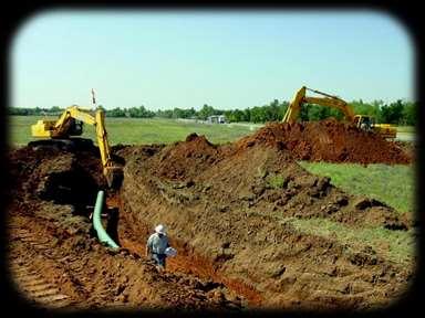
The purpose of this task is to prevent damage from occurring to the pipe or it s coating when backfilling an exposed pipeline.
 OQ Task Name Task 39.0 Backfill 1.0 Task Description This task applies to the process and material to backfill or cover a buried pipeline which has been excavated or otherwise exposed, Backfilling shall
Practice Test FOR GAS POSITIONS APTITUDE BATTERY
 Practice Test FOR GAS POSITIONS APTITUDE BATTERY INTRODUCTION The purpose of this Practice Test is to help you prepare for the Gas Positions Aptitude Battery placement exercise. A sample of questions based
1 Exam Prep NFPA 99 Health Care Facilities Questions and Answers (Plumbing Contractor)
") 1 Exam Prep NFPA 99 Health Care Facilities Questions and Answers (Plumbing Contractor) 1. According to NFPA 99, SCFM is an acronym for. a) Surface Conditions at Fahrenheit Mercury b) Standard Conditions
1 Exam Prep NFPA 99 Health Care Facilities Questions and Answers (Plumbing Contractor) 1. According to NFPA 99, SCFM is an acronym for. a) Surface Conditions at Fahrenheit Mercury b) Standard Conditions
SAFETY POLICY AND PROCEDURE MANUAL All Euramax Subsidiaries. Number K-3.0 Welding Safety Procedures
 Number K-3.0 Issued: 1/2009 Revised: 3/2016 Page 1 of 3 1.0 PURPOSE: To standardize procedures associated with production and maintenance welding and to minimize the potential risk of accident or injury
Section 20 TABLE OF CONTENTS Pressurized Equipment and Systems. 20.A General B Compressed Air and Gas Systems
 Section 20 TABLE OF CONTENTS Pressurized Equipment and Systems Section: Page 20.A General... 20-1 20.B Compressed Air and Gas Systems... 20-4 20.C Boilers and Systems... 20-7 20.D Compressed Gas Cylinders...
PRESSURIZED EQUIPMENT AND SYSTEMS
 SECTION 20 PRESSURIZED EQUIPMENT AND SYSTEMS 20.A GENERAL 20.A.01 Inspections and tests - general. a. Pressurized equipment and systems shall be inspected and performance tested before being placed in
TECHNICAL DATA MAINTENANCE AIR COMPRESSOR MODEL G-1
 Dry 131h 1. DESCRIPTION The Viking Model G-1 Maintenance Air Compressor is an electric motor-driven, aircooled, single-stage, oil-less compressor. The unit is equipped with a check valve and provides a
Handling and Storage of Gases
 Handling and Storage of Gases Learning Outcome When you complete this module you will be able to: Describe the procedures for safe storage and handling of cylinders containing gases. Learning Objectives
[Reserved] Packagings ICC 3 1 3AA 3AL 3AX 3A480X 3AAX
![[Reserved] Packagings ICC 3 1 3AA 3AL 3AX 3A480X 3AAX](/thumbs/80/80792632.jpg "[Reserved] Packagings ICC 3 1 3AA 3AL 3AX 3A480X 3AAX") 173.300 [Reserved] 173.301 General requirements for shipment of compressed gases and other hazardous materials in cylinders, UN pressure receptacles and spherical pressure vessels. (a) General qualifications
173.300 [Reserved] 173.301 General requirements for shipment of compressed gases and other hazardous materials in cylinders, UN pressure receptacles and spherical pressure vessels. (a) General qualifications
SAFETY MANUAL FOR FLAMMABLE PRODUCT TRANSFER
 SAFETY MANUAL FOR FLAMMABLE PRODUCT TRANSFER SUPPLIMENT TO eom IMPORTANT READ THIS MANUAL BEFORE PRODUCT INSTALLATION, OPERATION, INSPECTION & MAINTENANCE Tougher and more rigid guidelines are being established
Spilt body Flange ball valve. TC-205MFF-PN1640 User Manual English Version. Document No: TC-205MFF-PN1640.Ur-manual. Date: 2007/04/2617. Version: 1.
 Spilt body Flange ball valve TC-205MFF-PN1640 Series PED Category I,II TC-205MFF-PN1640 User Manual English Version Use for company in Europe who will place the product on the market, please amend which
Item ID: Rev.: 00 Status: Final Effective Date: 29-Feb-2015 EXECUTIVE SUMMARY
 EXECUTIVE SUMMARY The objective of this report is to demonstrate that sections of pipeline between MLV 401 and MLV 402 on the Canadian Mainline Line 400-2 meet the applicable requirements in CSA Z662-15
Safety. April 2018 Supersedes all previous publications 2018 Chevron Phillips Chemical Company LP
 Technical Note 802 Leak Testing of Polyethylene Pipe For Municipal and Industrial Applications Part 1 Pre-Test Considerations Leak testing may be used to find leaks in a newly constructed or newly modified
Limited quantities of compressed gases.
 173.306 Limited quantities of compressed gases. (a) Limited quantities of compressed gases for which exceptions are permitted as noted by reference to this section in 172.101 of this subchapter are excepted
East Building, PHH-30 U.S. Department New Jersey Avenue S.E. of Transportation Washington, D.C DOT-SP (ELEVENTH REVISION)
") East Building, PHH-30 U.S. Department 1200 New Jersey Avenue S.E. of Transportation Washington, D.C. 20590 Pipeline and Hazardous Materials Safety Administration DOT-SP 11808 (ELEVENTH REVISION) EXPIRATION
East Building, PHH-30 U.S. Department 1200 New Jersey Avenue S.E. of Transportation Washington, D.C. 20590 Pipeline and Hazardous Materials Safety Administration DOT-SP 11808 (ELEVENTH REVISION) EXPIRATION
Type 1367 High-Pressure Instrument Supply System with Overpressure Protection
 Instruction Manual D100343X012 Type 1367 November 2017 Type 1367 High-Pressure Instrument Supply System with Overpressure Protection TYPE 252 FILTER 2ND-STAGE TYPE 67CF FILTER-STYLE REGULATOR INLET TYPE
DESIGN DATA A WET PIPE BLADDER TANK FOAM/WATER SYSTEM WITH HYDRAULICALLY ACTUATED DELUGE CONCENTRATE CONTROL VALVE
 February 9, 1998 Foam 101a A BLADDER TANK WITH 1. DESCRIPTION A Wet Pipe Bladder Tank Foam/Water System is a standard wet pipe automatic sprinkler system capable of discharging a foam/water solution automatically
INSTRUCTIONS FOR FORM RSPA F (1-2001) ACCIDENT REPORT - HAZARDOUS LIQUID PIPE SYSTEMS GENERAL INSTRUCTIONS
 ACCIDENT REPORT - HAZARDOUS LIQUID PIPE SYSTEMS GENERAL INSTRUCTIONS") INSTRUCTIONS FOR FORM RSPA F 7000-1 (1-2001) ACCIDENT REPORT - HAZARDOUS LIQUID PIPE SYSTEMS GENERAL INSTRUCTIONS Each hazardous liquid pipeline operator shall file Form RSPA F 7000-1 for an accident that
INSTRUCTIONS FOR FORM RSPA F 7000-1 (1-2001) ACCIDENT REPORT - HAZARDOUS LIQUID PIPE SYSTEMS GENERAL INSTRUCTIONS Each hazardous liquid pipeline operator shall file Form RSPA F 7000-1 for an accident that
15ME-014 INSTRUCTION MANUAL OF STERN TUBE SEALING TYPE EVK2RV. URL
 15ME-014 E INSTRUCTION MANUAL OF STERN TUBE SEALING TYPE EVK2RV URL http://www.kemel.com CONTENTS [A] Installation [B] Piping [C] Inspection [D] Handling [E] Parts replacement intervals [F] Handling check
1.0 Scope and Application. 2.0 Definitions. Cal Poly Risk Management Confined Space Program Page 1
 Page 1 1.0 Scope and Application The following procedures describe safe operating practices in confined spaces. These may be sewers, pipelines, tanks, boiler compartments, ducts, vaults, pits, vats, bins
CITY AND COUNTY OF DENVER CR&CF RISK UNIT Compressed Gas Safety Standard
 CITY AND COUNTY OF DENVER CR&CF RISK UNIT 65.5.11 Compressed Gas Safety Standard 1.0 Introduction 2.0 Scope This standard has been developed to protect all City and County of Denver employees and contractors
Model PSI Compressor with 3-Gallon Air Tank 12VDC
 Model 6350 150 PSI Compressor with 3-Gallon Air Tank 12VDC IMPORTANT: It is essential that you and any other operator of this product read and understandd the contents of this manual before installing
FUNDAMENTALS OF PRESSURE RELIEF VALVES IN NATURAL GAS INSTALLATION - OPERATION - MAINTENANCE. Gary S. Beckett
 FUNDAMENTALS OF PRESSURE RELIEF VALVES IN NATURAL GAS INSTALLATION - OPERATION - MAINTENANCE Gary S. Beckett Flow Safe Supply 10727 Tower Oaks Boulevard Houston, Texas 77070 What Are They and Why Are They
Overview EUSSAM12. Carry out tightness testing and direct purging of gas installations
 Overview This standard covers tightness testing and direct purging of low or medium pressure gas, in accordance with approved procedures and practices. It covers the standards required to meet the requirements
Compressed Gas Cylinders - Guideline
 Environmental Health and Safety Compressed Gas Cylinders - Guideline Date of Issuance: 1/10/18 Revision Number: Initial Revision Date: Prepared by: EH&S 1. Purpose Carnegie Mellon University has developed
Periodic Survey of Fuel Installations on Ships other than Liquefied Gas Carriers utilizing gas or other low flash point fuels
 (Jan 2017) Periodic Survey of Fuel Installations on Ships other than Liquefied Gas Carriers utilizing gas or other low flash point fuels CONTENTS 1. Application 2. Special Survey 2.1 Schedule 2.2 Scope
Investigation of failures
 49 CFR 192.617 192.617 Investigation of failures Each operator shall establish procedures for analyzing accidents and failures, including the selection of samples of the failed facility or equipment for
TYPICAL TOXIC GAS SYSTEM INSPECTION VIOLATIONS
 TYPICAL TOXIC GAS SYSTEM INSPECTION VIOLATIONS The following is a list of typical violations often found by inspectors and a generic solution. You can use this list to improve the safety of your facility,
Composite Pistol-Type Air Needle Scaler OWNER S MANUAL
 Composite Pistol-Type Air Needle Scaler OWNER S MANUAL WARNING: Read carefully and understand all INSTRUCTIONS before operating. Failure to follow the safety rules and other basic safety precautions may
PURPOSE OF THE POLICY
 Title: Safe Storage, Handling, Use and Disposal Procedures of Compressed Gas Cylinders Effective Date: November 2005 Revision Date: March 1, 2017 Issuing Authority: Responsible Officer: VP, Capital Projects
TECHNICAL DATA. Page 1 of 8. model f /2 (dn40) & 2 (dn50)
 & 2 (dn50)") Page 1 of 8 1. DESCRIPTION The Viking Model F-1 Deluge Valve is a quick opening, differential diaphragm, flood valve with one moving mechanism. The Deluge Valve is used to control water flow in Deluge
Page 1 of 8 1. DESCRIPTION The Viking Model F-1 Deluge Valve is a quick opening, differential diaphragm, flood valve with one moving mechanism. The Deluge Valve is used to control water flow in Deluge
PNEUMATIC STOPPERS OPERATING MANUAL. Type F G H - FOG
 OPERATING MANUAL PNEUMATIC STOPPERS Type F G H - FOG This document is property of SO.CA.P. s.r.l. LISSONE - ITALY - ANY DUPLICATION IS FORBIDDEN Rev 07 del 01/11/2016 info@socapsrl.com - www.socapsrl.com
MSC Guidelines for Pressure Vessels
 References: a. 46 CFR Part 54 Pressure Vessels S. T. Brady, CDR, Chief, Engineering Division b. ASME Boiler and Pressure Vessel Code (BPVC), Section VIII, Division 1, (1998 Edition) c. Navigation and Inspection
Apollo Standard Port, Full Port & One Piece Flanged Ball Valves Installation, Operation, & Maintenance Manual
 I854000.D Apollo Standard Port, Full Port & One Piece Flanged Ball Valves Installation, Operation, & Maintenance Manual Introduction This manual presents guidelines for the Installation, Operation and
SECTION BUTTERFLY VALVES
 SECTION 15112 BUTTERFLY VALVES PART 1 GENERAL 1.01 SUMMARY A. All butterfly valves shall be of the tight closing, rubber seated type and fully comply with the latest revision of AWWA Standard C504, Class
OPERATING PROCEDURES
 OPERATING PROCEDURES 1.0 Purpose This element identifies Petsec s Operating Procedures for its Safety and Environmental Management System (SEMS) Program; it applies to all Petsec operations. Petsec is
USER MANUAL. 1. Principle of operation. 2. Delivery condition. SPRING-LOADED SAFETY VALVES zarmak. Edition: 07/2016 Date: V (ex.
 ZETKAMA Sp. z o.o. ul. 3 Maja 12 PL 57-410 Ścinawka Średnia SPRING-LOADED SAFETY VALVES zarmak USER MANUAL 782V (ex. 782) Edition: 07/2016 Date: 01.07.2016 TABLE OF CONTENTS 1. Principle of operation 2.
AIR-OPERATED DOUBLE DIAPHRAGM PUMP USER S MANUAL
 00, 0, 000 00, 000, 00 A. TECHNICAL INFORMATION Model 00 Inlet/Outlet " Air Inlet /" 0 / 000 /" /" 00 /" /" 000 /" /" 00 /" /" Flow Rate GPM/ 0LPM GPM/ 0LPM GPM/ LPM GPM/ LPM GPM/ 0LPM GPM/ 0LPM Maximum
General Inspection Guidance for Waste Management Units Requiring Air Emission Controls Under RCRA Air Standard Subpart CC
 United States Environmental Protection Agency RCRA Programs Branch Region IV Atlanta, GA CAA/RCRA Air Rules 27 November 2000 General Inspection Guidance for Waste Management Units Requiring Air Emission
TECHNOLOGIES. M Series. Positive return metering pumps [API675]
![TECHNOLOGIES. M Series. Positive return metering pumps [API675]](/thumbs/90/101415964.jpg "TECHNOLOGIES. M Series. Positive return metering pumps [API675]") M Series Positive return metering pumps [API675] Hydraulic double diaphragm metering pump in AISI 316L stainless steel A line of plunger and hydraulic double diaphragm metering pumps designed according
M Series Positive return metering pumps [API675] Hydraulic double diaphragm metering pump in AISI 316L stainless steel A line of plunger and hydraulic double diaphragm metering pumps designed according
Full Internal Relief Valves Instruction Manual
 Full Internal Relief Valves Instruction Manual MEV200FIR & MEV300FIR Application: Designed for use in mobile LPG & NH 3 containers as a primary pressure relief valve for bobtail and transport trailer installations.
Health and Safety at Work (Hazardous Substances Reduced Secondary Containment for Certain Above Ground Stationary Tanks) Safe Work Instrument 2017
 Safe Work Instrument 2017") Health and Safety at Work (Hazardous Substances Reduced Secondary Containment for Certain Above Ground Stationary Tanks) Safe Work Instrument 2017 This safe work instrument is approved under section 227
Health and Safety at Work (Hazardous Substances Reduced Secondary Containment for Certain Above Ground Stationary Tanks) Safe Work Instrument 2017 This safe work instrument is approved under section 227
Be our partner in safe, reliable natural gas delivery
 Wide Web at. pipeline operators. The industry has a proven record of safety. Por favor visite para Main, House Main Wide Web at. pipeline operators. The industry has a proven record of safety. Por favor
INJECTION ODORIZING SYSTEMS : DOSAODOR TYPE
 0198GB Rev. 02 - Page 1/6 - English INJECTION ODORIZING SYSTEMS : DOSAODOR TYPE The contents of this publication are presented for informational purposes only, and while every effort has been made to ensure
MUELLER. Xp, & Lineseal 350 Butterfly Valves
 Installation/Operating Manual MUELLER Lineseal Iii, Lineseal Xpii, Lineseal Xp, & Lineseal 350 Butterfly Valves! WARNING: 1. Read and follow instructions carefully. Proper training and periodic review
Operation and Maintenance Plan. Master Meter Gas Distribution Systems
 Operation and Maintenance Plan For Master Meter Gas Distribution Systems MASTER METER SYSTEM A natural gas pipeline system for distributing natural gas for resale within, but not limited to, a distinct
6.6 Relief Devices. Introduction
 6.6 Relief Devices Introduction Relief devices are used to help prevent a catastrophic failure of equipment and/or minimize the effects of any unanticipated or uncontrolled events. As such, relief devices
Regulations Respecting Compressed Gas Pressure Vessels
 COMPRESSED GAS PRESSURE VESSELS SR 99/70 1 Regulations Respecting Compressed Gas Pressure Vessels Repealed by Chapter B-5.1 Reg 1 (effective January 1, 2007) Formerly Saskatchewan Regulations 99/70 (effective
PIP PNE00012 Piping Examination and Leak Test Guide
 October 2017 Piping PIP PNE00012 Piping Examination and Leak Test Guide PURPOSE AND USE OF PROCESS INDUSTRY PRACTICES In an effort to minimize the cost of process industry facilities, this Practice has
RULES PUBLICATION NO. 119/P
 RULES PUBLICATION NO. 119/P PERIODIC SURVEYS OF FUEL INSTALLATIONS ON SHIPS OTHER THAN LIQUEFIED GAS CARRIERS UTILIZING GAS OR OTHER LOW FLASH POINT FUELS 2019 January Publications P (Additional Rule Requirements)
TP1 and TP2 Temporary Cone Shaped Strainers
 1698051/2 IM-P169-07 ST Issue 2 TP1 and TP2 Temporary Cone Shaped Strainers Installation and Maintenance Instructions TP1 1. Safety information 2. General product information 3. Installation and commissioning
Process Name Compressed Gas Cylinders Program
 CNM WAY PROCESS CNM Process Name Compressed Gas Cylinders Program (07/11/2018 Revision) Overview of Compressed Gas Cylinders Program Purpose: To prevent injury from failure of compressed gas cylinders
EXAMPLES OF COMPLIANCE METHODS FOR MONITORING AND RECORDKEEPING RCRA SUBPARTS BB AND CC. Tennessee Operations Eastman Chemical Company
 EXAMPLES OF COMPLIANCE METHODS FOR MONITORING AND RECORDKEEPING RCRA SUBPARTS BB AND CC Tennessee Operations Eastman Chemical Company 1 Tennessee Operations of Eastman Chemical Company Large Manufacturing
INOGATE Technical Secretariat UK Experience European Standards Implementation Key Expert Phil Winnard Session 2 Georgia, October 2015
 INOGATE Technical Secretariat UK Experience European Standards Implementation Key Expert Phil Winnard Session 2 Georgia, October 2015 BUILDING PARTNERSHIPS FOR ENERGY SECURITY www.inogate.org EN 12186
INTENDED USE TECHNICAL SPECIFICATIONS
 1/2IN. HEAVY-DUTY AIR IMPACT WRENCH OWNER S MANUAL WARNING: Read carefully and understand all INSTRUCTIONS before operating. Failure to follow the safety rules and other basic safety precautions may result
USER INSTRUCTIONS LARGE HOOK & STRAP ANCHORAGE CONNECTOR ! WARNING
 ROSE MODEL NUMBER USER INSTRUCTIONS LARGE HOOK & STRAP ANCHORAGE CONNECTOR! WARNING National standards and state, provincial and federal laws require the user to be trained before using this product. Use
STANDARD SPECIFICATION FOR SPLIT TEES (HOT TAP MATERIAL)
") STANDARD SPECIFICATION FOR SPLIT TEES (HOT TAP MATERIAL) TEE (HOT TAPPING MATERIAL) S-04-02-040 Page 1 of 7 1.0 SCOPE This specification covers the basic requirements for the design, manufacture and supply
STANDARD SPECIFICATION FOR SPLIT TEES (HOT TAP MATERIAL) TEE (HOT TAPPING MATERIAL) S-04-02-040 Page 1 of 7 1.0 SCOPE This specification covers the basic requirements for the design, manufacture and supply
Installation of Ballast Water Management Systems
 (Sept 2015) (Rev.1 May 2016) Installation of Ballast Water Management Systems 1. Application In addition to the requirements contained in BWM Convention (2004), the following requirements are applied to
APCO ARV CLEAN WATER AIR RELEASE VALVES. Model 50A
 APCO ARV CLEAN WATER AIR RELEASE VALVES Model 50A Instruction D12013 February 2017 Instructions These instructions provide installation, operation and maintenance information for APCO ARV Clean Water Air
Piped Air SCBA Refilling System Standard
 WALT WHITE Fire Chief 5770 Freeport Blvd., Suite 200 Sacramento, CA 95822-3516 Ph: (916) 808-1300 Fax: (916) 808-1629 www.sacfire.org Piped Air SCBA Refilling System Standard SCOPE: This specification
HOT OILING OPERATIONS ALL HSE PRC 172. Approved By: Manager, HSE Performance Assurance. Table of Contents
 Owner: HSE Performance Assurance ALL HSE PRC 172 Approved By: Manager, HSE Performance Assurance Retention Code: CG01 CA Revised: March 2015 Review Frequency: Five years or less Table of Contents 1.0 Purpose...
TECHNICAL DATA. the Viking Pilot Pressure Regulating Valve 1 Model A-1 Speed Control Assembly: OBSOLETE. the Viking Speed Control Assembly 1
 November 30, 1994 534 a 1. PRODUCT NAME VIKING 2" (50mm), 3" (75mm), 4" (100mm), 6" (150mm) 2. MANUFACTURER THE VIKING CORPORATION 210 N. Industrial Park Road Hastings, Michigan 49058 U.S.A. Telephone:
Steam System Best Practices 14 Best Practices for Guide Lines for Boiler Plant Log Books
 Steam System Best Practices 14 Best Practices for Guide Lines for Boiler Plant Log Books 1. SCOPE OF BOILER LOGBOOK PROGRAM In all cases, there are minimum tasks and functions for an operator to perform
3 GALLON, OILLESS PANCAKE COMPRESSOR INSTRUCTIONS. Item #31289
 3 GALLON, OILLESS PANCAKE COMPRESSOR INSTRUCTIONS Item #31289 The EASTWOOD 3 GALLON, OILLESS PANCAKE COMPRESSOR, with an Integral Air Regulator, efficiently supplies all compressed air requirements for
ONSHORE GAS GATHERING FAQS
 ONSHORE GAS GATHERING FAQS These Frequently Asked Questions (FAQs) are intended to clarify, explain, and promote better understanding of the gas gathering line rules. These FAQs are not substantive rules
CastCreations PRODUCT DESCRIPTION. Redwood Stump Fire Pit Item #: C1002. CastCreations Ph: Aurora, Utah
 CastCreations PRODUCT DESCRIPTION Redwood Stump Fire Pit Item #: C1002 Manufactured by: Questions or Concerns? CastCreations Ph: 1-435-529-3350 PO Box 155 E-mail: info@ccfandw.com Aurora, Utah UNIT COMPONENTS
Consult with manufacturers concerning permeation of the pipe walls, jointing materials, valve seats, etc.
 Design Manual Chapter 4 - Water Mains 4C - Facility Design 4C-1 Facility Design A. General Water mains and appurtenances, including hydrants and valves, should be provided along all streets including connections
DF1 and DF2 Diffusers
 1550650/4 IM-P155-07 ST Issue 4 and Diffusers Installation and Maintenance Instructions 1. Safety information 2. General product information 3. Installation 4. Commissioning 5. Operation 6. Maintenance
WHAT IS GAS TANK/CYLINDER?
 Introduction To use compressed gas cylinders safely, it is important that they are stored properly, handled correctly, used with the correct equipment, and that the properties of the gases they contain
Subj: PIPELINE AND HOSE TESTING GUIDANCE FOR MARINE TRANSPORTATION RELATED FACILITIES HANDLING OIL OR HAZARDOUS MATERIAL IN BULK
 Commandant United States Coast Guard 2703 Martin Luther King Jr. Ave. SE Washington DC 20593-7501 Staff Symbol: CG-FAC-2 Phone: (202) 372-1145 Email: HQS-PF-fldr-CG-FAC-2@uscg.mil NAVIGATION AND VESSEL
Hot Work Program. University of Wisconsin-Platteville Reviewed 4/2016
 Hot Work Program University of Wisconsin-Platteville Reviewed 4/2016 The purpose of the Hot Work Program is to establish safety procedures for employees, contractors, and subcontractors engaging in any
Installation and Operation Instructions
 Bentintoshape llc Installation and Operation Instructions Fire Pit - Hidden Tank Models www.bentintoshape.net INTRODUCTION Your bentintoshape Cor-Ten Steel Gas Fire Pit is designed for installation in
PROCEDURES FOR REPAIRS TO ASME NV STAMPED PRESSURE RELIEF DEVICES OF NUCLEAR SAFETY RELATED PRESSURE RELIEF VALVES
 NB16 0603 NR Task Group 1 9 16 1. One update by NR task group page 3: 7/17/19 2. Two updates to S6.1 and S6.3 on page 1: 7/19/17 SUPPLEMENT 6 PROCEDURES FOR REPAIRS TO ASME NV STAMPED PRESSURE RELIEF DEVICES
Telefon (+45) Telefax (+45)
 Telefax (+45)") Uni-Valve A /S VENTILER & INSTRUMENTER Telefon (+45) 43 43 82 00 Telefax (+45) 43 43 74 75 mail@uni-valve.com www.uni-valve.com UNI-S83 / S84 3/4-way ball valve Installation and Operating manual 3/4-WAY
Uni-Valve A /S VENTILER & INSTRUMENTER Telefon (+45) 43 43 82 00 Telefax (+45) 43 43 74 75 mail@uni-valve.com www.uni-valve.com UNI-S83 / S84 3/4-way ball valve Installation and Operating manual 3/4-WAY
TABLE OF CONTENTS PART 2 - CONFINED SPACES
 May 11, 2006 TABLE OF CONTENTS PART 2 - CONFINED SPACES Page DEFINITIONS... 2-1 GENERAL... 2-2 RESPONSIBILITIES... 2-2 HAZARD ASSESSMENT AND WORK PROCEDURES... 2-3 IDENTIFICATION AND ENTRY PERMITS... 2-3
Compact Ball Valves ASAHI AV VALVES. Contents. User s Manual. (Page) (1) Be sure to read the following warranty clauses of our product 1
 (1) Be sure to read the following warranty clauses of our product 1") Serial No. H-V030-E-5 Compact Ball Valves User s Manual Contents (Page) (1) Be sure to read the following warranty clauses of our product 1 (2) General operating instructions 2 (3) General instructions
Serial No. H-V030-E-5 Compact Ball Valves User s Manual Contents (Page) (1) Be sure to read the following warranty clauses of our product 1 (2) General operating instructions 2 (3) General instructions