EZ LOADER AUTOMATIC PALLET POSITIONER. United States Patent USA European Patent United Kingdom France Germany Other Patents Pending
|
|
|
- Camron Hudson
- 6 years ago
- Views:
Transcription


1 EZ LOADER AUTOMATIC PALLET POSITIONER United States Patent USA European Patent United Kingdom France Germany Other Patents Pending
2 Date Placed in Service: Serial Number: Dealer: Version 1.04 BISHAMON INDUSTRIES CORPORATION 5651 East Francis Street Ontario, California 91761, USA (909) (800)
3 Name of manufacturer: Address of manufacturer: Name of Manufacturer s authorized representative: DECLARATION OF CONFORMITY Bishamon Industries Corporation 5651 E. Francis Street Ontario, California 91761, USA The Technical Construction File is maintained at: (Print name) IMS ZI-Rue Saint Gilles BONNEVAL I hereby declare that the following machinery complies with all the Essential Health and Safety Requirements of the Machinery Directive 2006/42/EC as amended. Machinery description: Serial no.: EZ Loader (Pneumatic Load Positioner) 1105***to date Transposed Harmonized European Standards used: EN 12100: 2010 Safety of Machinery General principles for design Risk assessment and risk reduction EN 349: 1993+A1: 2008 Safety of Machinery - Minimum gaps to avoid crushing of parts of the human body EN 13857: 2008 Safety of Machinery - Safety distances to prevent danger zones being reached by the upper and lower limbs EN 983:1996+A1:2008 Safety of Machinery - Safety requirements for fluid power systems and components Pneumatics EN :2007 Safety of Machinery Risk assessment Part 1: Principles Additional standards used: ANSI MH Safety Requirements for Industrial Scissors Lifts Name of responsible person: Position of responsible person: Robert M. Stone Vice President of Operations DECLARATION: I declare that as the authorized responsible person, the above information in relation to the supply / manufacture of this product is in conformity with the stated standards and other related documents following the provisions of the EC Machinery Directive. Signature of responsible person: date: 09 / 08 /2011 Robert M. Stone day/mth/year Signature of authorized representative: date: / / (Print name) day/mth/year

4 Table of Contents Contents Page Getting Started...1 Inspection...1 General Warnings...1 Safety Warning Label Locations...2 Specifi cations and Specifi cation Drawing...3 Recommended Floor Area & Ceiling Height...4 Functional Description...5 Scissor Blocking Instructions....6 Installation....7 Installation Instructions....8 Quick Set-up....9 Set-up Procedure....9 Operating Instructions...11 Handling Instructions...12 Routine Maintenance...12 List of Figures Figure 1 - Safety Warning Label Locations... 2 Figure 2 - Specifi cation Drawing... 3 Figure 3 - Recommended Floor Area & Ceiling Height... 4 Figure 4 - Functional Drawing... 5 Figure 5 - Maintenance Bar Operation... 6 Figure 6 - EZ Loader Pneumatic Components... 7 Figure 7 - Air Gauge... 7 Figure 8 - EZ Adjust Knob Positions... 8 Figure 9 - Handling the EZ Loader... 9 Figure 10 - EZ Loader Height vs Load Diagram Figure 11 - Fitting Disassembly...13 Figure 12 - EZ Loader Pneumatic Schematic List Of Charts Chart 1 - EZ Adjust Capacity Adjustability... 9 Chart 2 - EZ Loader Performance... 15
5 GETTING STARTED PLEASE READ THIS MANUAL CAREFULLY BEFORE USING THE EZ LOADER. The safety of all persons installing, using or servicing the EZ Loader is of utmost importance to Bishamon. The EZ Loader is capable of supporting heavy loads and is capable of causing SEVERE PERSONAL INJURY if used improperly or if certain safety precautions are not taken. When properly used and maintained, the EZ Loader will provide many years of safe, trouble free service. If you have any questions about any of the instructions in this manual or about the use of this product, PLEASE contact your DEALER or Bishamon Industries Corporation. INSPECTION IMMEDIATELY upon receipt of the EZ Loader, remove all packing and strapping material and visually inspect the unit for damage. Any damage to the unit MUST BE NOTED on the delivery receipt. After the preliminary inspection is conducted, the unit should be thoroughly inspected for any concealed damage that was not readily apparent during the preliminary inspection. Any concealed damage found that was not noted on the delivery receipt should be IMMEDIATELY reported in writing TO THE DELIVERING CARRIER. SAFETY DEFINITIONS Bishamon uses the following system to identify the degree of risk associated with hazards and unsafe practices. WARNING - Hazard or unsafe practice which, if not avoided, could result in DEATH or SEVERE PERSONAL INJURY and PROPERTY DAMAGE. CAUTION - Hazard or unsafe practice which, if not avoided, may result in MINOR or MODERATE PERSONAL INJURY and PROPERTY DAMAGE. GENERAL WARNINGS WARNING 1. READ THIS MANUAL COMPLETELY BEFORE USING AND THOROUGHLY UNDERSTAND AND FOLLOW ALL SAFETY INSTRUCTIONS. 2. The EZ Loader is designed for use with stable, uniformly distributed loads on a solid level fl oor. DO NOT concentrate the load at one point on the pallet or platform. ALWAYS uniformly distribute each layer of load over the supporting surface. DO NOT use the EZ Loader for any purpose other than its intended use. 3. SHEARING HAZARD. ALWAYS keep hands and feet clear of the scissor mechanism and all moving components. DO NOT put hands under the platform when in use. SEVERE PERSONAL INJURY could result. 4. CRUSHING HAZARD. ALWAYS keep hands and feet clear of all moving components. DO NOT put feet on the base frame when in use. SEVERE PERSONAL INJURY could result. 5. PINCH POINT HAZARD. ALWAYS keep hands and fi ngers clear of the underside of the rotator ring. SEVERE PERSONAL INJURY could result. 6. NEVER sit, stand or ride on the platform or rotating surface. Moving components could cause loss of balance. SEVERE PERSONAL INJURY could result. 7. NEVER go under the platform until the load is removed and the scissor mechanism is blocked. SEVERE PERSONAL INJURY could result. 8. NEVER place any load on the EZ Loader with the scissor mechanism blocked. SEVERE PERSONAL INJURY and PROPERTY DAMAGE could result. 9. DO NOT overpressurize or overload the EZ Loader. ALWAYS stay within the designated pressure and capacity ratings. SEVERE PERSONAL INJURY and PROPERTY DAMAGE could result. 1


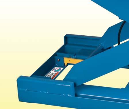
6 10. When removing a loaded pallet, ALWAYS raise the load until the bottom of the pallet clears the top of the EZ Loader before backing up. ALWAYS stay well clear of the load while it is being removed from the EZ Loader. SEVERE PERSONAL INJURY and PROPERTY DAMAGE could result. 11. ALWAYS ensure all safety warning labels are in place and legible. If not, remove the EZ Loader from service and replace the required labels. Refer to Figure 1 for label descriptions and locations. 12. Before servicing any component in the EZ Loader s pneumatic system, ALWAYS open the purge valve and discharge all air pressure. SEVERE PERSONAL INJURY could result. 13. DO NOT infl ate the air spring when removed from the EZ Loader. Pressurizing the unrestricted air spring may cause assembly to burst. SEVERE PERSONAL INJURY and PROPERTY DAMAGE could result. 1. ALWAYS use clean dry air to pressurize the system. CAUTION 2. If the EZ Loader is equipped with the optional semi-live portability, ALWAYS remove the load before engaging the portability wheels. SAFETY WARNING LABEL LOCATIONS Figure 1 Safety Warning Label Locations 2
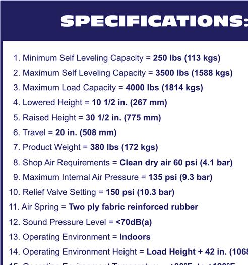
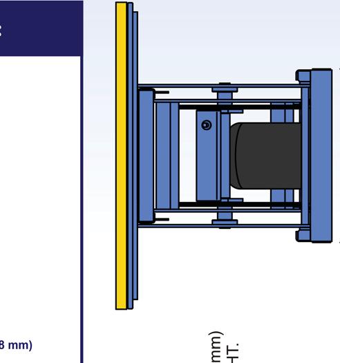
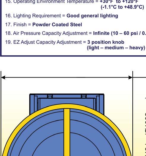
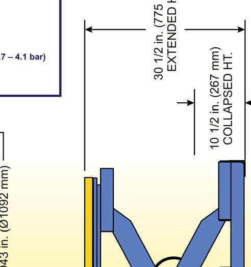
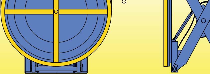

7 SPECIFICATIONS AND SPECIFICATION DRAWING Figure 2 Specifi cation Drawing 3

 extending beyond the danger")
 +")
8 RECOMMENDED FLOOR AREA & CEILING HEIGHT Figure 3 Recommended Floor Area & Ceiling Height The EZ Loader s recommended fl oor area, shown in Figure 3, identifi es the Danger Zone and the Operating Zone. The Danger Zone is the area inside the base frame and under the platform structure. The recommended Operating Zone is a distance of 39 inches (1 meter) extending beyond the danger zone on all sides. The EZ Loader also requires a minimum ceiling height to operate within. The minimum floor-to-ceiling height should be calculated as Load Height (including the pallet) + 42 inches (1068 mm). 4


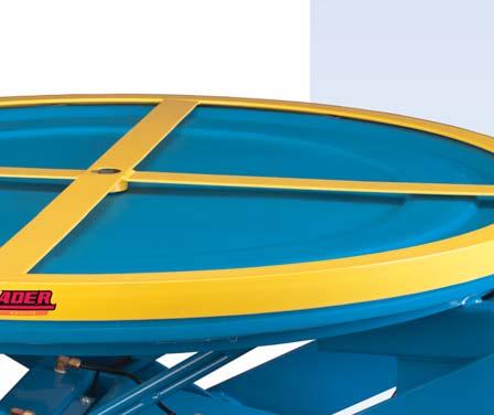
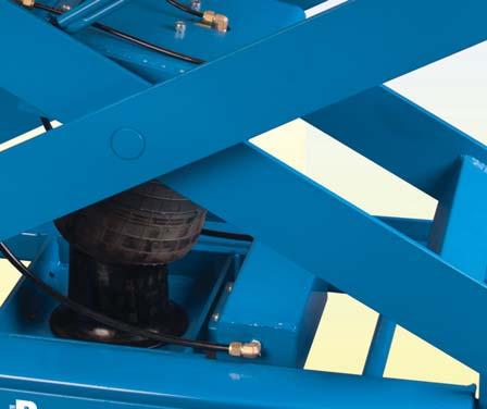
9 FUNCTIONAL DESCRIPTION The EZ Loader is a pneumatic pallet positioner designed to assist the operator when manually loading or unloading a palletized load. As the load weight increases or decreases the EZ Loader gradually lowers or raises to maintain the top of the load at a comfortable working height, eliminating operator strain due to bending and stretching. The EZ Loader is completely variable in capacity. Load support is provided by a Firestone Airstroke Actuator in a captive air system. Load capacity and height is initially determined by the initial system pressure in the fully raised position. The initial pressure varies from approximately 10 psi (0.7 Bar) to 60 psi (4.1 Bar). This corresponds to a collapsed capacity range from approximately 250 lbs (113 kgs) to a maximum of 2700 lbs (1225 kgs). In addition to the initial system pressure, the EZ Loader has the EZ Adjust capacity adjustment feature which is independent of the system air pressure. For any initial air pressure setting, the EZ Loader has three (3) collapsed capacity settings; light, medium and heavy. A capacity change can be made at any time without the need to add or remove air and is as easy as turning a knob. All additional load above the collapsed capacity is added to the EZ Loader while it is in the collapsed position. The maximum load capacity is 4000 lbs (1814 kgs). Figure 4 Functional Drawing 5


10 SCISSOR BLOCKING INSTRUCTIONS To Engage The Maintenance Bars 1. Remove all load from the platform and allow the EZ Loader to extend to its fully raised position. 2. As detailed in Figure 5, lift each maintenance bar until the bottom of the bar contacts the scissor axle. Ensure both maintenance bars completely engage the axle. 3. Turn the EZ Adjust knob (identifi ed in Figure 6), to the charge/discharge position and slowly open the purge valve to release the air from the system. As the air releases, the scissor mechanism will lower and completely engage the maintenance bars. ALWAYS check the position of the bars before going under the platform. To Disengage The Maintenance Bars Figure 5 Maintenance Bar Operation 4. Ensure the capacity adjustment knob is in the charge/discharge position and the purge valve is closed. Repressurize the EZ Loader to the desired initial pressure or until the EZ Loader is fully raised. 5. Push each maintenance bar to its lowest (stored) position. WARNING NEVER place any load on the EZ Loader with the scissor mechanism blocked. SEVERE PERSONAL INJURY and PROPERTY DAMAGE could result. 6


11 INSTALLATION Installation of the EZ Loader is a simple process; however, certain precautions must be taken to ensure years of trouble free service. The EZ Loader requires clean, dry, compressed air to operate properly. A fi lter and regulator with a pressure gauge should be installed on an air line in the installation area before initially charging the system for use. Before you begin, locate and identify the pneumatic components detailed in Figure 6. These components will be referred to in the Installation and the Set-Up procedures. Make sure you understand the function of each component before proceeding. Figure 6 EZ Loader Pneumatic Components Air Chuck - The air chuck is supplied the EZ Loader and is used to charge the EZ Loader with air. The air chuck body is supplied with 1/4 inch female pipe threads and must be attached to the end of the air line extending from the fi lter/regulator. Air Gauge - The air gauge, Figure 7, indicates the EZ Loader s internal system pressure. Green identifi es the initial pressure range for the EZ Loader in the raised position. The initial system pressure should be between 10 psi (0.7 bar) and 60 psi (4.1 bar). Yellow identifi es the operation pressure range when the EZ Loader is fully loaded and collapsed. The maximum operational pressure is 135 psi (9.3 bar). Under no circumstance should be EZ Loader be operated in the red range above 135 psi (9.3 bar). Purge Valve - The purge valve is a manual one way valve used to release air from the EZ Loader. Turning the valve counter-clockwise opens the valve and releases air from the system. Turn the valve clockwise to close. The valve should be closed with fi nger tight pressure. DO NOT use a wrench to close the valve. Leakage may occur if over-tightened. Figure 7 Air Gauge Tank Valve - The tank valve is a one way valve used to charge the EZ Loader with air. The end of the tank valve is designed to mate with the air chuck. Pressing the air chuck against the end of the tank valve allows air to enter the system. EZ Adjust Knob - The EZ Adjust capacity adjustment knob allows the operator to change the collapsed capacity of the EZ Loader without adding or removing air from the system. The knob s three (3) positions are identifi ed in Figure 8. Light Weight Position - is also the air charge/discharge position. Always turn the EZ Adjust knob to this position before adding or removing air from the system. The Light Weight 7

12 Position also corresponds to the lightest load setting. For any air pressure setting, this position will allow the EZ Loader to completely collapse with the least amount of load. Medium Weight Position - is the medium load capacity setting. At this setting, the EZ Loader will collapse slower and will require more load to completely compress the platform to its collapsed position. Heavy Weight Position - is the high load capacity setting. With the EZ Adjust knob in this position, the EZ Loader will require the most load to completely collapse the platform. Figure 8 EZ Adjust Knob Positions INSTALLATION INSTRUCTIONS 1. Make sure the installation area is clean before starting. Check the installation surface to ensure it is relatively smooth and level. Otherwise, the EZ Loader base frame should be shimmed to make it level. 2. Using a fork lift or similar equipment, move the palletized EZ Loader to the location it is to be installed. 3. Remove the steel bands securing the EZ Loader to the pallet. Next, remove all packing material and place it off to the side. 4. Attach the air chuck to the air line extending from the fi lter/regulator. 5. Set the regulator to 60 psi (4.1 bar). Turn the EZ Adjust knob to the Light Weight Position and initially charge the system by engaging the air chuck to the EZ Loader s tank valve. The air spring will infl ate and the EZ Loader will gradually extend to its maximum raised height. If escaping air is detected, close the purge valve (fi nger tight). Allow the system to completely pressurize and disengage the air line from the EZ Loader. 6. Using a fork lift, position the forks under the platform structure, as detailed in Figure 9. Lift the EZ Loader off the pallet. Next, remove the pallet and place if off to the side. Position the EZ Loader in the desired location. 7. Securing the EZ Loader to the fl oor may be preferred in some applications. If so, the base frame of the EZ Loader has 4 pre drilled holes for lagging the unit securely to the fl oor. Using the 4 holes as a template, mark the holes on the fl oor. Using the fork lift, shift the position of the EZ Loader to allow room for drilling, then drill. When complete, reposition the lift and install anchors lagging the EZ Loader securely to the fl oor. NOTE: Make sure the base angles are fully supported along their entire length with shims or concrete grout. 8. The EZ Loader is now ready for operation. Refer to the Set Up procedure to properly set the initial pressure for the desired capacity. 8
 in the raised position.")


13 QUICK SET-UP Figure 9 Handling the EZ Loader The EZ Loader is complete variable in capacity and very easy to set up. Complete the installation instructions detailed on page 8 Turn the EZ Adjust knob to the Light Weight Position and pressurize the EZ Loader to 60 psi (4.1 bar) in the raised position. Place all or any portion of the load on the EZ Loader, then open the purge valve to release air and set the top of the load at the desired working height. Close the purge valve fi nger tight. Next, turn the EZ Adjust knob to the Medium Weight Position leaving one position for lighter loads and one position for heavier loads. For a more detailed explanation, refer to the following set up procedure. Note: To ensure proper operation, always add or remove air with the EZ Adjust knob in the Light Weight Position. SET-UP PROCEDURE The load capacity and height of the EZ Loader is initially determined by the system pressure in the raised position. The initial pressure is completely variable and for most applications should be between 10 psi (0.7 bar) and 60 psi (4.1 bar). An initial pressure less than the minimum stated above can be used; however, the EZ Loader will not extend to its maximum height. In addition, to the system air pressure setting, the operator may adjust the collapsed capacity of the EZ Loader by turning the EZ Adjust knob. For any air pressure setting, the EZ Loader has three (3) collapsed capacity settings; Light Weight Position, Medium Weight Position and Heavy Weight Position. A capacity change can be made at any time without the need to add or remove air and is as easy as turning the EZ Adjust knob. The change in capacity for two (2) air pressure settings is shown below in Chart 1. Chart 1 EZ Adjust Capacity Adjustability 9

 is added to the EZ Loader while it is in the collapsed position. To set up the EZ Loader for use, complete steps 1")
14 A diagram of the rotator ring height as it relates to the load weight for the EZ Loader is shown below in Figure 10. Figure 10 illustrates the change in performance due to both changes in initial pressure and changes in the EZ Adjust knob position. Figure 10 EZ Loader Height vs. Load Diagram For most applications, the EZ Loader should be completely collapsed at approximately 75 percent of the total load (load + pallet weight). The remaining load (usually the last layer) is added to the EZ Loader while it is in the collapsed position. To set up the EZ Loader for use, complete steps 1 6 below. 1. The EZ Loader must be properly installed before using. Refer to installation instructions on page Set the air regulator to 60 psi (4.1 bar). Turn the EZ Adjust knob to the Light Weight Position and completely pressurize the EZ Loader. Check the pressure gauge on the EZ Loader to ensure the system pressure is the same as the regulator setting. Disengage the air chuck from the tank valve and store the air line in a convenient location. Ensure the purge valve is closed fi nger tight and disengage the maintenance bars, if required. 3. Place the pallet and 75 percent of a lighter than average load on the EZ Loader. Check the platform height. If the EZ Loader is not completely collapsed, open the purge valve slowly and release air until the minimum height is obtained. Close the purge valve. 4. Using a fork lift, remove the loaded pallet and allow the EZ Loader to return to its raised position. If a dedicated air line is being used, set the air regulator to the initial pressure on the gauge. Otherwise, record the setting for future use. 5. With the EZ Loader in the fully raised position, turn the EZ Adjust knob to the Medium Weight Position. This provides for one lighter than average weight setting; as well as, one heavier than average weight setting. 6. The EZ Loader is now ready for use. Should the load capacity vary, adjustments in the load height or collapsed capacity can easily be made by turning the EZ Adjust knob. 10


15 Note: The ideal initial pressure setting depends on many factors; including load density, load height, load variability and operator height. Should the desired response require a slightly stiffer spring setting, simply remove the load, turn the EZ Adjust knob to the Light Weight Position and add air. Typically, a 5 psi (0.3 bar) change in initial pressure is adequate. Likewise, if a slightly softer spring setting is desired, simple remove air. The EZ Loader is a captive air system much like an automotive tire and will lose small amounts of air over a period of time. Therefore, air will have to be occasionally added to the system. OPERATING INSTRUCTIONS Loading Operations 1. Place the empty pallet on the EZ Loader rotator ring. Be sure that the pallet is centered on the rotator ring before beginning. 2. Begin the loading process. Always uniformly distribute each layer of load over the pallet surface. As the load weight increases, the EZ Loader will gradually lower to maintain the top of the load at a convenient working height. 3. Upon completion of the loading process, rotate the pallet to a position that is suitable for the fork lift forks to enter the pallet. Slowly lift the loaded pallet until the bottom of the pallet clears the top of the EZ Loader. Next, slowly back up until the load is well clear of the EZ Loader s operating zone and others. Then, lower the load to a convenient height for transportation. Unloading Operations 4. Using a fork lift, lift the loaded pallet to a height where the bottom of the pallet clears the top of the EZ Loader. Position the loaded pallet over the top of the EZ Loader rotator ring. Be sure that the pallet is centered over the rotator ring before lowering the load. Slowly lower the load until the EZ Loader is completely collapsed. Next, slowly back up until the forks are well clear of the EZ Loader s operating zone. 5. Begin the unloading process. Always remove each layer of load completely before beginning the next layer. This will ensure that the remaining layers are uniformly distributed over the pallet surface. As the load weight decreases, the EZ Loader will gradually raise to maintain the top of the load at a convenient working height. 6. Upon completion of the unloading process, remove the empty pallet. 11


16 EZ Adjust Knob Operation 1. The EZ Adjust knob provides for quick and easy capacity changes without the need to add or remove air. The amount of capacity change for each knob position is relative to the initial system pressure. However, each knob position changes the collapsed capacity by approximately 40%. 2. The position of the EZ Adjust knob can be changed at any time during the loading or unloading cycle. For example, if the EZ Adjust knob is in the Medium Weight Position and the platform is settling to quickly with the fi rst layer of load, simply turn the knob to the Heavy Weight Position. Likewise, if the response is too stiff after the fi rst layer of load, turn the knob to the Light Weight Position. 3. Adjusting the EZ Adjust knob during a loading or unloading cycle will cause an imbalance in the system air pressure in the various reservoirs. If after several mid-cycle adjustments the performance becomes undesirable, simply equalize the system pressure by turning the EZ Adjust knob to the Light Weight Position when the EZ Loader is in the fully raised position. Wait a few seconds for the pressure to equalize and return the knob to the desired position. HANDLING INSTRUCTIONS Certain applications may require the EZ Loader to be relocated frequently. Handling the EZ Loader can be easily accomplished as follows: 1. Remove all load from the platform and allow the EZ Loader to extend to its fully raised position. 2. Using a fork lift, position the forks under the platform structure, as detailed in Figure Slowly lift the EZ Loader until the base frame clears the fl oor. The EZ Loader can now be moved to the next location. ROUTINE MAINTENANCE The EZ Loader is designed to provide years of trouble free service and requires very little maintenance. However, a routine inspection and maintenance program will prevent costly replacement of parts and/or downtime. 12

17 WARNING NEVER go under the platform until the load is removed and the scissor mechanism is blocked. SEVERE PERSONAL INJURY could result. WARNING Before servicing any component in the EZ Loader s pneumatic system, ALWAYS open the purge valve and discharge all air pressure. SEVERE PERSONAL INJURY could result. Monthly inspection should consist of the following: 1. Inspect the snap rings at all rollers and linkage assemblies. If not in place and/or secure, replace or repair at once. 2. Inspect all rollers for signs of wear. Replace as necessary. Rollers and axles have lifetime lubricated bearings; therefore, they do not need to be greased or lubricated. 3. Inspect the air spring retaining screws for tightness. Tighten if necessary. 4. Inspect the rotator ring bearings for ease of operation. Replace if necessary. 5. Should removal of the air lines be required, mark the initial position before removing the fi tting nut. When reinstalling, fi rst tighten the nut by hand, then using a wrench rotate the nut to the original position. Tighten the nut an additional 1/8 turn. Do not over tighten as air leakage may occur. 6. Inspect the EZ Adjust knob and valve body for proper operation. If disassembly of the valve is required, always engage the maintenance bars and open the purge valve to completely discharge all air pressure before disassembling the valve. Figure 11 Fitting Disassembly 13

18 REPLACEMENT PARTS Figure 12 EZ Loader Pneumatic Schematic Bishamon has carefully selected the components used in the manufacture of the EZ Loader. In the event replacement parts are required, ALWAYS use genuine EZ Loader components provided by Bishamon. These parts can be obtained from your Bishamon DEALER or by contacting Bishamon Industries Corp. For detailed exploded views and parts lists contact your dealer, Bishamon Industries Corporation or visit www. bishamon.com. 14

 of the possible settings are: 25 psi with the EZ Adjust knob in position three, 35 psi with the EZ Adjust knob in position two, 50 psi with the EZ")

19 Notes: Chart 2 EZ Loader Performance 1. The above chart is for reference only to illustrate the capacity variability of the EZ Loader. Other initial pressures may be better suited for a specifi c loading/unloading application. 2. There are multiple EZ Loader settings for most pallet weights. For example, consider a total pallet load of 1650 lbs. Three (3) of the possible settings are: 25 psi with the EZ Adjust knob in position three, 35 psi with the EZ Adjust knob in position two, 50 psi with the EZ Adjust knob in position one. Each setting will provide a slightly different load response and the ideal setting will depend of the load height, number of layers in the load and the operator height. 3. The above chart assumes a typical load height with the last layer of load being placed on the pallet with the EZ Loader fully compressed. 4. The EZ Loader is completely variable in capacity and any initial pressure setting between 10 psi and 60 psi may be used. 15
ModelsEZU-15 & EZU-15-R. BISHAMON INDUSTRIES CORPORATION 5651 East Francis Street Ontario, California 91761, USA (909) (800)
 (800)") UP P n e u m a t i c ModelsEZU-15 & EZU-15-R BISHAMON INDUSTRIES CORPORATION 5651 East Francis Street Ontario, California 91761, USA (909) 390-0055 (800) 231-3187 Table of Contents GETTING STARTED......................................
UP P n e u m a t i c ModelsEZU-15 & EZU-15-R BISHAMON INDUSTRIES CORPORATION 5651 East Francis Street Ontario, California 91761, USA (909) 390-0055 (800) 231-3187 Table of Contents GETTING STARTED......................................
INSTALLATION, OPERATION AND SERVICE MANUAL ABS AIR BAG LIFT
 INSTALLATION, OPERATION AND SERVICE MANUAL ABS AIR BAG LIFT P.O. Box 1058 1058 West Industrial Avenue Guthrie, OK 73044-1058 405-282-5200 FAX: 405-282-8105 www.autoquip.com Item # 830ABS Version 1.0 07/2001
HANDBOOK. Squeeze Off Unit SOU 250. Please refer any queries to:
 HANDBOOK Squeeze Off Unit SOU 250 Please refer any queries to: Hy Ram Engineering Co Ltd Pelham Street Mansfield Nottinghamshire NG18 2EY Telephone No: (01623) 422982 Please note all queries should state
HANDBOOK. Squeeze Off Unit SOU 400. Please refer any queries to:
 HANDBOOK Squeeze Off Unit SOU 400 Please refer any queries to: Hy Ram Engineering Co Ltd Pelham Street Mansfield Nottinghamshire NG18 2EY Telephone No: (01623) 422982 Please note all queries should state
SHHP50 FLOOR STANDING HYDRAULIC PRESS
 SHHP50 FLOOR STANDING HYDRAULIC PRESS OWNER S MANUAL FOR YOUR SAFETY PLEASE READ THESE INSTRUCTIONS CAREFULLY AND RETAIN THEM FOR FUTURE USE. SPECIFICATION MAX CAPACITY STROKE WORK RANGE WEIGHT 50 TON
Owner s Manual Air Bag Lift Tables
 Owner s Manual Air Bag Lift Tables SOUTHWORTH PRODUCTS CORP PO Box 1380, Portland, ME 04104-1380 Telephone: 1-800-743-1000 or 207-878-0700 Fax: 207-797-4734 www.southworthproducts.com service@southworthproducts.com
MANUAL. Sesame. Thermoplastic Tank Technologies
 MANUAL Sesame Thermoplastic Tank Technologies INSTALLATION AND USER GUIDE CONTENT 1. GENERAL 3 2. IMPORTANT 3 3. INSTALLATION EXPANSION VESSEL 4 4. USE EXPANSION VESSEL 5 5. AIR CELL REPLACEMENT 5 5.1
Differential Pressure Regulator Type Type 45-6 (0.1 to 1 bar, DN 15) Mounting and Operating Instructions EB 3226 EN
 Mounting and Operating Instructions EB 3226 EN") Differential Pressure Regulator Type 45-6 Type 45-6 (0.1 to 1 bar, DN 15) Mounting and Operating Instructions EB 3226 EN Edition March 2008 Contents Contents Page 1 Design and principle of operation...................
Differential Pressure Regulator Type 45-6 Type 45-6 (0.1 to 1 bar, DN 15) Mounting and Operating Instructions EB 3226 EN Edition March 2008 Contents Contents Page 1 Design and principle of operation...................
SALCO PRODUCTS, INC. PRESSURE RELIEF VALVE STORAGE, INSTALLATION, OPERATING, MAINTENANCE/TESTING, AND INSPECTION INSTRUCTIONS
 STORAGE INSTRUCTIONS Until it is time to install a new or reconditioned valve on the car, the valve must be kept in its original packaging in order to protect it from dirt and damage. INSTALLATION INSTRUCTIONS
Roto-Max Work Positioner. Operation. Maintenance
 Roto-Max Work Positioner Operation Maintenance Lift Products Inc. P.O Box 349 Elm Grove Wisconsin 53122-0349 PH: 877-543-8776 FX: 262-521-5725 Manual #19950 1 WARNING Do not operated this lift table unless
HYDRAULIC PALLET TRUCKS. MODEL Nos: PT550BC, PT685BC, PT550NC, PT685NC OPERATION & MAINTENANCE INSTRUCTIONS
 HYDRAULIC PALLET TRUCKS MODEL Nos: PT550BC, PT685BC, PT550NC, PT685NC OPERATION & MAINTENANCE INSTRUCTIONS 0711 WARNING! PT550NC MAXIMUM LOAD - 2000KG PT685NC MAXIMUM LOAD - 2000KG PT550BC MAXIMUM LOAD
Type S301 & S302 Gas Regulators INTRODUCTION INSTALLATION. Scope of Manual. Description. Specifications. Type S301 and S302. Instruction Manual
 Fisher Controls Instruction Manual Type S301 & S302 Gas Regulators October 1981 Form 5180 WARNING Fisher regulators must be installed, operated, and maintained in accordance with federal, state, and local
Installation Instructions WARNING: WARNING: WARNING: LP AND HIGH ALTITUDE LP GAS CONVERSION KIT FOR UNITED STATES INSTALLATIONS
 LP AND HIGH ALTITUDE LP GAS CONVERSION KIT FOR UNITED STATES INSTALLATIONS Installation Instructions For Model Series *G7/*GC2 Furnaces and Appliances Using Honeywell Gas Valves. BEFORE THE CONVERSION
IMPORTANT: RECEIVING INSTRUCTIONS:
 Instruction Sheet Sidewinder Mechanical Bender IMPORTANT: RECEIVING INSTRUCTIONS: Visually inspect all components for shipping damage. If any shipping damage is found, notify carrier at once.shipping damage
General Information. NTA607HD Lift Assist Adjustments. Tools Required. Work Location. Notations and Conventions U B F D R B F L
 Great Plains Manufacturing, Inc. 1 NTA607HD Lift Assist Adjustments Null4: When you see this symbol, the subsequent instructions and warnings are serious - follow without exception. Your life and the lives
20 Ton SD Shop Press Operating Instructions
 20 Ton SD Shop Press Operating Instructions MODEL NO. 850SD Hazard Symbols Used in the Manuals This manual includes the hazard symbols defined below when the operations or maintenance job involves a potential
75 Ton SD Shop Press Operating Instructions
 75 Ton SD Shop Press Operating Instructions MODEL NO. 856SD Hazard Symbols Used in the Manuals This manual includes the hazard symbols defined below when the operations or maintenance job involves a potential
Operation Manual Piston Sensed Gas Pressure Regulators
 687 Technology Way Napa, CA 94558 Phone: (707) 259-0102 FAX: (707) 259-0117 www.aptech-online.com Operation Manual Piston Sensed Gas Pressure Regulators (Models KT9, KT10, Welded KT10, KT12) Table of Contents:
30T A/Manual Hydraulic Shop Press
 30T A/Manual Hydraulic Shop Press Operation Manual 1 1. Important Information 1.1 Safety Information 1.1.1 Hazard Symbols Used in the Manuals This manual includes the hazard symbols defined below when
EASTERN ENERGY SERVICES PTE LTD. 60 Kaki Bukit Place #02-19 Eunos Tech Park Singapore, SG Singapore Telephone: Fax:
 2 Table Of Contents 1. Introduction 3 2. About this Manual 3 3. Contacting YZ Systems 3 4. Vessel Components 4 5. Specifications 5 6. Application 6 7. Theory of Operation 7 8. DuraSite Installation & Use
User Instruction Manual
 User Instruction Manual 4500 psi Air Compressor Ver 2, 1.18 Contents Parts Included...3 Assembly Instructions...3-5 Operation Instructions...6-7 Oil Change Intervals...8 Air Filter Replacement...9 Setting
MAYHEM MAYHEM OWNERS MANUAL. Paintball Guns International. Manufactured by
 MAYHEM MAYHEM OWNERS MANUAL Manufactured by Paintball Guns International Table of Contents Specifications...................... 2 Parts diagram and Listing............. 3 Description of Marker Operation.......
C - SERIES. Height Adjustable Portable Goal Supports. Installation & Owner s Instructions C1000 C2000. Made in the USA
 C - SERIES Height Adjustable Portable Goal Supports C1000 C2000 Installation & Owner s Instructions Made in the USA This manual explains the proper installation, operation, and maintenance of your Schutt
4 IN. BALL LAUNCHER Engine Mounted / PTO Driven
 4 IN. BALL LAUNCHER Engine Mounted / PTO Driven OPERATOR S PARTS and MAINTENANCE MANUAL 2006 EDITION BL-MAN-4EN Creation Revision date: 10MAR06 date: by: Ivon LeBlanc by: Table of Contents Table of Contents...
Assembly Drawing: W-311B-A01, or as applicable Parts List: W-311B-A01-1, or as applicable Special Tools: , , &
 REDQ Regulators Model 411B Barstock Design Powreactor Dome Regulator OPERATION AND MAINTENANCE Contents Scope..............................1 Installation..........................1 General Description....................1
2,500/4,000 LB Easy Riser Vertical Cable Feighner Lift
 2,500/4,000 LB Easy Riser Vertical Cable Feighner Lift CAUTION - PUT SAFETY FIRST 1. Before attempting to install or operate this lift, study and fully understand the proper operating procedures and safety
U.S. Patent No. 7,922,246. Patents Pending
 U.S. Patent No. 7,922,246 Patents Pending 2 Table of Contents Page General Information... 3 Warnings and Cautions... 4 Tools... 6 SmartDock Parts... 6 Initial Set-Up and Adjustment... 7 Select Valve Retaining
MANUAL BE SERIES Test Benches
 The CustomCrimp Manual BE Series Test Benches are designed with features that make proof and burst testing of hydraulic hose assemblies a quick and easy procedure. CUSTOMIZED AND SPECIAL DESIGN BENCHES
TESCOM 50-4X Series Safety, Installation & Start-Up Procedures
 Operations & Service Manual TESCOM 50-4X Series Safety, Installation & Start-Up Procedures Do not attempt to select, install, use or maintain this product until you have read and fully understood this
1805 Series Relief Valves
 Instruction Manual Form 1211 1805 Series October 2011 1805 Series Relief Valves! WARNING Failure to follow these instructions or to properly install and maintain this equipment could result in an explosion
Owner s Manual Air Bag Lift Tables
 Owner s Manual Air Bag Lift Tables Airbag Lift Manual for PPA, GTA, GLSA & GLTA Models SOUTHWORTH PRODUCTS CORP PO Box 1380, Portland, ME 04104-1380 Telephone: 1-800-743-1000 or 207-878-0700 Fax: 207-797-4734
Retractable Hose Reel with 3/8" x 50' PVC Hose
 Retractable Hose Reel with 3/8" x 50' PVC Hose Item# 4816153 Owner s Manual Assembly and Operation Instructions MADE IN CHINA Read carefully and understand all ASSEMBLY AND OPERATION INSTRUCTIONS before
Natural Gas to L.P. Gas Conversion Kit
 Natural Gas to L.P. Gas Conversion Kit For Bosch 96% AFUE Gas Furnace, BGH96 Model Installation Instructions 3124627 2 Natural Gas to L.P. Gas Conversion Kit Installation Instructions Data subject to change
Product Information News September 26, 2003
 Product Information News September 26, 2003 LEVER HEIGHT INSPECTION FOR FIREHAWK MMR MSA is announcing a revision to the instructions for the Firehawk MMR Second Stage Regulator as they relate to the air
5 Gallon Pressure Pot with HVLP Spray Gun and Hose
 California Air Tools 5 Gallon Pressure Pot with HVLP Spray Gun and Hose Model No. 365 Technical Data Type of feed.pressure Maximum pressure in the tank... 0,413Mpa (60PSI) Working pressure in the tank.0,
TECHNICAL DATA. the Viking Pilot Pressure Regulating Valve 1 Model A-1 Speed Control Assembly: OBSOLETE. the Viking Speed Control Assembly 1
 November 30, 1994 534 a 1. PRODUCT NAME VIKING 2" (50mm), 3" (75mm), 4" (100mm), 6" (150mm) 2. MANUFACTURER THE VIKING CORPORATION 210 N. Industrial Park Road Hastings, Michigan 49058 U.S.A. Telephone:
310 SERIES TILT-TO-LOAD ROTATOR. The Specialist In Drum Handling Equipment
 OPERATOR S MANUAL FOR MORSE TILT-TO-LOAD DRUM ROTATOR SAFETY INFORMATION: While Morse Manufacturing Co. drum handling equipment is engineered for safety and efficiency, a high degree of responsibility
TECHNICAL DATA Q= C. Table 1 - Specifications
 September 25, 2013 Pressure Regulation 537a 1. Description The Model B-3 Pilot Operated Pressure Control Valve is a factory assembled unit. The unit consists of a Model J-2 Halar coated Flow Control Valve,
Operator s Manual. with Maintenance Schedule. Fourth Edition Second Printing Part No
 Operator s Manual with Maintenance Schedule Fourth Edition Second Printing Part No. 82297 Operator s Manual Fourth Edition Second Printing Important Read, understand and obey these safety rules and operating
NB/NBR NITROGEN BOOSTER FOR AVIATION SERVICE
 NB/NBR NITROGEN BOOSTER FOR AVIATION SERVICE INSTALLATION, OPERATION & MAINTENANCE MANUAL INTERFACE DEVICES, INC. 230 Depot Road, Milford, CT 06460 Ph: (203) 878-4648, Fx: (203) 882-0885, E-mail: info@interfacedevices.com
WATER HEATER THERMAL EXPANSION TANKS Owner s Manual. Safety Instructions Installation Maintenance Warranty. Models: 2-5 Gallon Capacity
 WATER HEATER THERMAL EXPANSION TANKS Owner s Manual Safety Instructions Installation Maintenance Warranty Models: 2-5 Gallon Capacity Thank You for purchasing this Thermal Expansion Tank. Properly installed
TECHNICAL DATA. Table 1 - Specifications
 Page 1 of 6 1. DESCRIPTION Model A-3 Pilot Operated Pressure Control Valves are factory assembled units. Each unit consists of a Model H-2 Halar coated Flow Control Valve, a Speed Control Valve, a Model
HYDRAULIC MOBILE LIFTING TABLE
 HYDRAULIC MOBILE LIFTING TABLE MODEL NO: HTL300 & HTL500 PART NO: 7610148 & 76210152 OPERATION & MAINTENANCE INSTRUCTIONS ORIGINAL INSTRUCTIONS GC1116 INTRODUCTION Thank you for purchasing this CLARKE
FIRST TEAM SPORTS, INC Storm Portable Series Assembly Instructions
 FIRST TEAM SPORTS, INC Storm Portable Series Assembly Instructions WARNING! WARNING! WARNING! THIS BASKETBALL SYSTEM IS SPRING LOADED AND SHIPPED UNDER TENSION. ATTEMPTING TO ASSEMBLE OR DISASSEMBLE ANY
Installation & Operation Manual Proven Quality since 1892
 Content 1. ERIKS operating companies 2. Product description 3. Requirements for maintenance staff 4. Transport and storage 5. Function 6. Application 7. Installation 8. Maintenance 9. Service and repair
OPERATION MANUAL NTF-60 Plus
 OPERATION MANUAL NTF-60 Plus Nitrogen Tire Filling Valve Stem Caps (Qty=200) Order P/N 436075 RTI Technologies, Inc 10 Innovation Drive York, PA 17402 800-468-2321 www.rtitech.com 035-81264-00 (Rev A)
DIAPHRAGM PUMP MODEL PDM 1-175
 INSTRUCTION MANUAL DIAPHRAGM PUMP MODEL PDM 1-175 Manual : 0704 573.034.112 Date : 18/04/07 - Supersede : 17/06/02 - Modif. : + ATEX KREMLIN REXSON - 150, avenue de Stalingrad - 93245 STAINS Cedex - FRANCE
INSTALLATION COMMISSIONING, OPERATION & MAINTENANCE MANUAL
 WedgeRock RW Series Worm Gear Actuators INSTALLATION COMMISSIONING, OPERATION & MAINTENANCE MANUAL Revision 01 Date 4/3/17 Page 1 Table of Contents 1.0 INTRODUCTION... 4 1.1 PURPOSE... 4 1.2 AUDIENCE...
Natural Gas to L.P. Gas Conversion Kit
 Natural Gas to L.P. Gas Conversion Kit For Bosch 80% AFUE Gas Furnace, BGS80 Model Installation Instructions 3124627 2 Natural Gas to L.P. Gas Conversion Kit Installation Instructions Data subject to change
THE HF-300 SERIES. Operating and Service Manual. Series includes all variants of HF-300/301
 THE HF-300 SERIES Operating and Service Manual Series includes all variants of HF-300/301 Issue A July 2015 1 TABLE OF CONTENTS 1. Description... 3 2. Installation... 3 3. Operation... 4 3.1. Spring Loaded...
BUTTERFLY VALVES Series 800
 BUTTERFLY VALVES Series 800 WARNING Before proceeding read ALL instructions and become familiar with the equipment and associated drawings. Follow ALL applicable safety regulations and codes for pressurized
Installation and Service Manual
 An Actuant Company Installation and Service Manual Heavy Duty Hydraulic Stabilization Legs CONTENTS Part # 3010003129 REV 0D Section Page 1.0 Receiving Instructions 2 2.0 Safety Issues 2 3.0 Hydraulic
THE MF-400 SERIES. Operating and Service Manual. Series includes all variants of MF-400/401
 THE MF-400 SERIES Operating and Service Manual Series includes all variants of MF-400/401 Issue A October 2013 1 TABLE OF CONTENTS 1. Description... 3 2. Installation... 3 3. Operation... 4 4. Special
PORTABLE 5 GALLON AIR TANK ASSEMBLY & OPERATING INSTRUCTIONS
 PORTABLE 5 GALLON AIR TANK MODEL 472 ASSEMBLY & OPERATING INSTRUCTIONS 349 Mission Oaks Blvd., Camarillo, CA 930 Visit our Web site at http://www.harborfreight.com TO PREVENT SERIOUS INJURY, READ AND UNDERSTAND
!!!! SERVICE MANUAL PRESSURE POT 2 GALLON. Service Manual: LT Washington St 931 Progress Ave., #7
 EXEL North America, Inc. EXEL Industrial Canada, Inc. 1310 Washington St 931 Progress Ave., #7 West Chicago, IL 60185 Scarborough ONT, M1G 3V5 Ph : (800) 573 5554 Ph : (800) 450 0655 Fx : (800) 664 1511
Marine 6-Boat Free-Standing Racks SKU: Updated November 2011
 Marine 6-Boat Free-Standing Racks SKU: 30-061 Updated November 011 Contains: Marine -Boat Free-Standing Racks (SKU 1-003) Marine 3 rd Boat Expansion Racks (SKU 1-0303) Marine Back Legs (SKU -001) 3 Sets
Model 130M Pneumatic Controller
 Instruction MI 017-450 May 1978 Model 130M Pneumatic Controller Installation and Operation Manual Control Unit Controller Model 130M Controller is a pneumatic, shelf-mounted instrument with a separate
INSTALLATION INSTRUCTIONS. CVS 67CFR Pressure Reducing Instrument Supply Regulator INTRODUCTION
 INSTALLATION INSTRUCTIONS CVS 67CFR Pressure Reducing Instrument Supply Regulator INTRODUCTION The CVS Controls 67CFR Filter regulator is a pressure reducing supply regulator typically used for pneumatic
Operation Manual. Diaphragm Sensed Gas Pressure Regulators
 687 Technology Way Napa, CA 94558 Phone: (707) 259-0102 FAX: (707) 259-0117 www.aptech-online.com Diaphragm Sensed Gas (AP/AZ/AK Models: 20, 100, 500, 1000, 1000T 10PA, 1100, 1200, 12PA, 1300, 1400T, 14PA,
Operating Instructions VETTER Industrial Lifting Bags 8 bar - Type IKV
 Industrial Pneumatics. Operating Instructions VETTER Industrial Lifting Bags 8 bar - Type IKV Article No. 87015301 Vetter GmbH I 03/12 I Changes and errors excepted. Vetter Industrial Lifting Bags 8 bar
Operation Manual Air Saver Unit ASV5000 Series
 9IM-V066-b Operation Manual Air Saver Unit ASV5000 Series Thank you for your choice of Kuroda Pneumatics LTDs product on this time. Please read this operation manual carefully and use the product correctly.
Model 7989T Steel Pipe Squeezer Sch. 40 & Sch. 80. Operations Manual
 10-12 Steel Pipe Squeezer Sch. 40 & Sch. 80 Operations Manual 1.0 Introduction This manual is issued as a basic operation manual covering the Regent Model 7989T, Pipe Squeezer and Pump as manufactured
Instruction Manual. AlfaLavalSBAntiVacuumValve ESE02960-EN Original manual
 Instruction Manual AlfaLavalSBAntiVacuumValve ESE02960-EN3 2017-11 Original manual Table of contents The information herein is correct at the time of issue but may be subject to change without prior notice
WARNING: FOR OUTDOOR USE ONLY
 Certified to CSA International 4.96 US For Outdoor Gas Fireplaces A HIGHER STANDARD IN QUALITY AND APPEARANCE SAFE AND BEAUTIFUL OUTDOOR LARGO FIRE PIT FOR PROPANE AND *NATURAL GAS OWNER S MANUAL WARNING:
Jacuzzi. J-CQ420 Cartridge Filter Installation and Operating Instructions
 Jacuzzi J-CQ420 Cartridge Filter Installation and Operating Instructions IMPORTANT SAFETY PRECAUTIONS ATTENTION INSTALLER: This guide contains important information about the installation, operation and
OPERATION MANUAL NTF-15
 OPERATION MANUAL NTF-15 Nitrogen Tire Filling Valve Stem Caps (Qty=200) Order P/N 436075 RTI Technologies, Inc 10 Innovation Drive York, PA 17402 800-468-2321 www.rtitech.com 035-81235-00 (Rev B) TABLE
Auto-Rewind Hose Reels INSTRUCTION MANUAL FOR OXY-LPG MODEL
 Auto-Rewind Hose Reels INSTRUCTION MANUAL FOR OXY-LPG MODEL Introduction Thank you for purchasing a Retracta Auto Rewind Hose Reel. The Retracta range of hose reels are a breakthrough in industrial quality
English. Introduction. Safety Instructions. All Products. Inspection and Maintenance Schedules. Parts Ordering. Specifications WARNING WARNING
 Contents All Products... Gb-1 Control Valves... Gb-2 Control Valve Actuators... Gb-3 Regulators... Gb-3 Relief Valves... Gb-4 Instruments, Switches, and Accessories... Gb-4 Products Covered by Battery
1700ESL Kamvalok Coupler
 PART #H32138PA November 2008 1700ESL Kamvalok Coupler OPW Transport Series Dry Disconnect Couplings are considered the standard of the industry. For use on multi-compartment petroleum, solvent and chemical
Instruction Manual Updated 7/26/2011 Ver. 2.2
 4-Unit Model MB HTHP Filter Press #171-50-4: 115-Volt #171-51-4: 230-Volt Instruction Manual Updated 7/26/2011 Ver. 2.2 OFI Testing Equipment, Inc. 11302 Steeplecrest Dr. Houston, Texas 77065 U.S.A. Tele:
Safety, Operating and Maintenance Manual. TRAIN Rat DS9-TRAIN
 Safety, Operating and Maintenance Manual TRAIN Rat DS9-TRAIN Industry s first air powered entry tool! Quickly, quietly and reliably opens passenger train doors! Introducing the TRAIN Rat. This innovative
Float Operated Level Controllers
 CONTENTS Float Operated Level Controllers IM0015 Nov. 2014 PAGE Introduction 1 Scope 1 Description 1 Specification 1 Control Installation 2 INTRODUCTION Side Mount Back Mount Prior to installing, the instructions
Operation Manual Guillotine Cutter RC-5
 Operation Manual Guillotine Cutter RC-5 Technical Specifications General Safety/Operating Instructions Using the Guillotine Cutter/Crimper Blade Change Instructions Maintenance Instructions This is a detailed
MASTER TRUING STAND TS-3. Optional Dial indicator set with brackets Dial indicator bracket set only
 MASTER TRUING STAND TS-3 3 2 1 3 8 9 4 10 7 6 5 12 13 Optional 1555-1 Dial indicator set with brackets 1556-1 Dial indicator bracket set only 49 11 16 14 15 48 32 31 37 38 20 19 17 18 34 39 21 36 22 33
DBML-60/80 Squeeze Tool
 DBML-60/80 Squeeze Tool OPERATORS MANUAL Description The Mustang Model DBML-60/80 Hydraulic squeeze tool has been manufactured since 1995. A Mustang 3 3/4 bore doubleacting cylinder producing 41,000 lbs
RHPS Series PRV 2 all types of connections User Manual
 RHPS Series PRV 2 all types of connections User Manual Read the complete manual before installing and using the valve. Before removing a valve from the system for service, you must depressurize system
Design and Application Details MICRO-RATIO Valves
 Flow Control Valves Page 7003 Design and Application Details MICRO-RATIO Valves Principle of Operation MICRO-RATIO Valve assemblies typically consist of a fixed-gradient air butterfly valve mechanically
TECHNICAL DATA 3 MODEL G-3000 DRY VALVE RISER ASSEMBLY
 Page 1 of 13 1. DESCRIPTION The Viking 3 Model G-3000 Dry Valve Riser Assembly is equipped with a small profile, light weight, pilot operated valve that is used to separate the water supply from the dry
TECHNICAL DATA MAINTENANCE AIR COMPRESSOR MODEL G-1
 Dry 131h 1. DESCRIPTION The Viking Model G-1 Maintenance Air Compressor is an electric motor-driven, aircooled, single-stage, oil-less compressor. The unit is equipped with a check valve and provides a
Fisher Lever-Lock Handlever Actuators for POSI-SEAL A81 Rotary Valves
 Instruction Manual D103319X012 Lever-Lock Handlever Actuator Fisher Lever-Lock Handlever Actuators for POSI-SEAL A81 Rotary Valves Contents Introduction................................. 1 Scope of Manual.........................
HYDRAULIC INTENSIFIER Max. Pressure: See Intensifier Data Plate Weight: 16 Lbs. (7.26 kg)
") Form No. 102897 Operating Instructions for: HB443 HB444 HYDRAULIC INTENSIFIER Max. Pressure: See Intensifier Data Plate Weight: 16 Lbs. (7.26 kg) Definition: A devise that raises the inlet pressure to
Form No. 102897 Operating Instructions for: HB443 HB444 HYDRAULIC INTENSIFIER Max. Pressure: See Intensifier Data Plate Weight: 16 Lbs. (7.26 kg) Definition: A devise that raises the inlet pressure to
SIGNATURE DEF REELS Models: Bare Reel Reel Reel Reel
 SERVICE BULLETIN SB2023 Rev C 7/11 SIGNATURE DEF REELS Models: 2400-006 Bare Reel 2400-007 16 Reel 2400-008 20 Reel 2400-009 30 Reel Thoroughly read and understand this manual before installing, operating
Manual winch MANISTOR 100 and 200
 Manual wall winch Manual winch MANISTOR 100 and 200 Instruction manual UK 173-192.10-3 PRODUCT DEVELOPED AND MANUFACTURED ACCORDING TO NF EN 13157 STANDARD REGISTERED DESIGN To ensure the constant improvement
AIR/OVER HYDRAULIC JACK 20 TON
 AIR/OVER HYDRAULIC JACK 0 TON 4487 ASSEMBLY AND OPERATING INSTRUCTIONS 349 Mission Oaks Blvd., Camarillo, CA 930 Visit our Web site at http://www.harborfreight.com Copyright 999 by Harbor Freight Tools.
Freedom8 ShoeBox Compressor Manual
 Freedom8 ShoeBox Compressor Manual Warning!! This product is not a toy! Use or misuse can cause severe injury or death! Use only with adult supervision. This unit is only to be used with tanks, hoses and
Installation, Operation & Maintenance Manual for Flo-Max Coupler Bracket Model FM150
 Installation, Operation & Maintenance Manual for Flo-Max Coupler Bracket Model FM150 January 2013 Form FVC 084 - Rev 02 IMPORTANT: KEEP THIS DOCUMENT WITH THE PRODUCT UNTIL IT REACHES THE END USER. 1.
WW-720. Pressure Reducing Control Valve
 WW-720 Pressure Reducing Control Valve (Size Ranges: 2-4 and 6-14 ) Installation Operation & Maintenance Page 1 of 6 1. DESCRIPTION The Model 720 Pressure Reducing is an automatic control valve (powered
Model A Sleeve Valve Cement Retainer
 Ret. O.D. Model A Sleeve Valve Cement Retainer DIMENSIONAL DATA A B C D E F G H J K L M N P Q R 3.593 3.593 3.500 2.500 3.531 3.531 1.345 3.375.750.437 2.437 2.187 7.062 2.437 5.312 11.685 20.093 3.937
FX IMPACT OWNER S MANUAL
 made in sweden FX IMPACT OWNER S MANUAL Warranty Information All FX Airguns carry a One Year Warranty against faulty workmanship and defective materials. If it becomes necessary, first contact the dealer
1.0 - OPENING AND CLOSING THE DOOR
 The purpose of this manual is to provide the user with instructions on how to safely open and close, how to conduct routine maintenance, and how to install the PEI TWINLOCK Closure on a pressure vessel.
INSTALLATION & MAINTENANCE INSTRUCTION
 ARCHON Industries, Inc Liquid Level Gauges Models: BT-LLG ND-LLG INSTALLATION & MAINTENANCE INSTRUCTION Instruction No.: 1014.2 Revision Issued: 3/01/03 Approved: Engineering Manager Warning ONLY QUALIFIED
Instruction Manual. Alfa Laval SB Pressure Exhaust Valve ESE02965-EN Original manual
 Instruction Manual Alfa Laval SB Pressure Exhaust Valve ESE02965-EN1 2015-10 Original manual Table of contents The information herein is correct at the time of issue but may be subject to change without
 RT3 CAP NAILER OWNER S MANUAL Operation Safety Maintenance Warranty! www.stingerworld.com PLEASE READ! This manual contains important information about product safety. REV 09/14 WELCOME TO STINGER Congratulations
Apollo Standard Port, Full Port & One Piece Flanged Ball Valves Installation, Operation, & Maintenance Manual
 I854000.D Apollo Standard Port, Full Port & One Piece Flanged Ball Valves Installation, Operation, & Maintenance Manual Introduction This manual presents guidelines for the Installation, Operation and
Fisher Lever Lock Handlever Actuators for POSI SEAL A81 Rotary Valves
 Instruction Manual Lever-Lock Handlever Actuator Fisher Lever Lock Handlever Actuators for POSI SEAL A81 Rotary Valves Contents Introduction... 1 Scope of Manual... 1 Description... 1 Specifications...
Installation/User s Guide Guide de l Utilisateur Installations- /Gebrauchsanleitung. U.S. Patent No. 7,922,246. Patent Pending
 Installation/User s Guide Guide de l Utilisateur Installations- /Gebrauchsanleitung For International Markets U.S. Patent No. 7,922,246 Patent Pending 2 Table of Contents Page General Information... 3
GETZ EQUIPMENT INNOVATORS RECOVERY SYSTEM CLEAN AGENT FE-36 / HALOTRON 1 PART NO. 4G59751 OPERATIONS MANUAL
 GETZ EQUIPMENT INNOVATORS CLEAN AGENT FE-36 / HALOTRON 1 PART NO. 4G59751 OPERATIONS MANUAL GETZ EQUIPMENT INNOVATORS PEKIN, ILLINOIS, U.S.A. PHONE: (888) 747-4389 FAX: (309) 495-0625 Limited Warranty
Operator s Manual Series 2400 Material Lift
 October 2013 Operator s Manual Series 2400 Material Lift USA 7514 Alabonson Rd. Houston, TX 77088 ph: 281-999-6900 fax: 281-999-6966 CANADA 75 Saltsman Drive, Unit 5 Cambridge, Ontario N3H 4R7 ph: 519-653-5300
TECHNICAL DATA. Q = C v P S
 January 6, 2012 Preaction 347a 1. Description Viking supervised Double-Interlocked Electric/Pneumatic Release Preaction Systems utilize the Viking G-6000P Valve. The small profile, lightweight, pilot operated
The owner and all operators must be familiar with all of the operational guidelines laid out within this manual.
 1.0 Introduction INSTALLATION manual Thank you for purchasing the PRO lift! This machine has been constructed using some of the highest manufacturing standards of today. This manual has been made in order