METHODOLOGY FOR ASSESSING THE EFFECTS OF PLAIN DENTS, WRINKLE BENDS, AND MECHANICAL DAMAGE ON PIPELINE INTEGRITY
|
|
|
- Nathaniel Watkins
- 6 years ago
- Views:
Transcription
1 NACE International Corrosion 007 Conference & Expo March 11-15, 007, Nashville, Tennessee NACE METHODOLOGY FOR ASSESSING THE EFFECTS OF PLAIN DENTS, WRINKLE BENDS, AND MECHANICAL DAMAGE ON PIPELINE INTEGRITY Chris Alexander Stress Engineering Services, Inc. Houston, Texas Kirk Brownlee Stress Engineering Services, Inc. Houston, Texas ABSTRACT According to statistics compiled by the U.S. Office of Pipeline Safety, mechanical damage is one of the primary causes of pipeline failures in the United States. For more than 30 years a significant body of research has been collected in an effort to understand the failure mechanisms and mechanics associated with pipeline defects that include plain dents, wrinkle bends, and mechanical damage involving dents with gouges. In the U.S. organizations such as the Pipeline Research Council International, Gas Technology Institute, and the American Petroleum Institute have led the change in funding these research efforts, as well as other efforts from research organizations around the world. While some guidance is provided by the ASME B31.4 and B31.8 pipeline codes in assessing pipeline damage, there is no single document that captures the lessons learned from the extensive body of research and experience that currently exists. To a large extent this is related to the complexity of the subject; however, there is a significant need to develop for industry a method for ranking the severity of pipeline damage. At the present time there is no single method for doing this. This paper will provide insights on a proposed three-tiered system to help operators determine which defects represent the most serious threat to the structural integrity of their systems. The intent is to provide operators with a grading tool based on research testing, material characteristics, experience, and dent mechanics in order for repairs to be made in a manner that ensures the safe operation of pipeline systems. INTRODUCTION One of the most critical elements when assessing pipeline damage is classification of defects. There is a significant amount of information available in the open literature; however, one of the challenges is putting everything together in a manner that can be used to assess damage severity. This is one of the main purposes of this paper. The second purpose is to provide a systematic methodology for operators and pipeline service companies who are tasked with making decisions about what to do when pipeline damage occurs. Because of the extensive research that has been conducted world-wide relating to dented pipelines, it is possible to draw information required on a range of defect types. The driving motivation for many research programs is to develop a better understanding of damaged pipelines in an effort to characterize their behavior. As with many areas of engineering, the ability to accurately predict the response behavior of structures is important to ensure adequate safety and consistent performance. The complexities associated with damaged pipelines make this a challenging task. Material issues, corrosion, cyclic pressure conditions, soil-pipe interactions and complicated stress fields are but a few examples. Provided below are the major defect classifications that typically arise when assessing pipeline damage. Plain dents Constrained dents Gouges Mechanical damage Wrinkles This paper provides a detailed discussion on each of the above defects types and their effects of the performance of pipeline in terms of static and cyclic pressure service. Additionally, the paper will provide discussions on current regulations including those found in the ASME pipeline codes and 30 CFR 50 and 49 CFR 190 thru
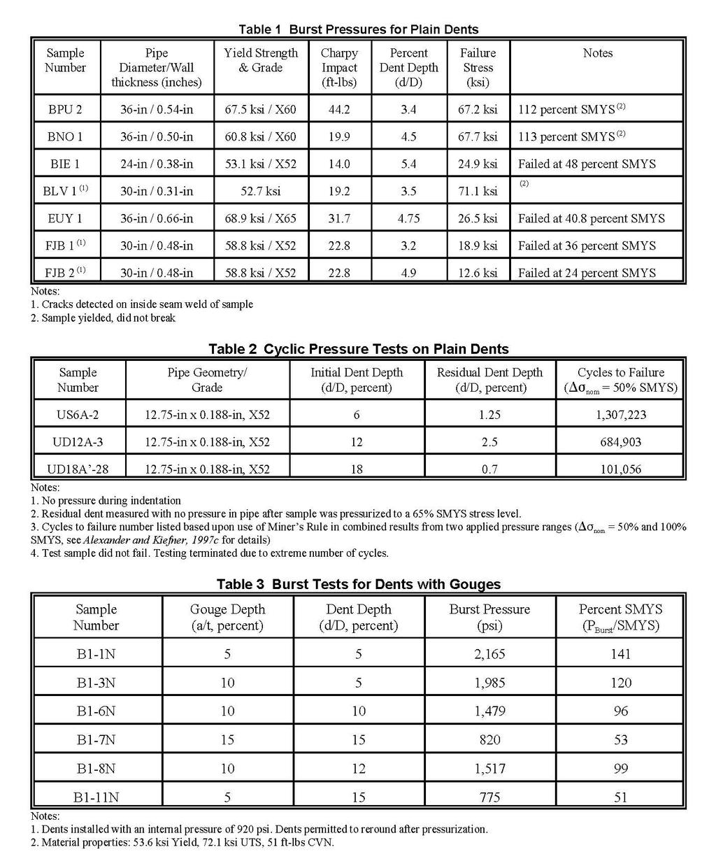
2 PIPELINE CODES AND REGULATIONS From an application standpoint, the current codes are viewed by many as over-conservative. Like many codes that were developed prior to extensive research programs such as those detailed herein, the pipeline code writers chose to take such positions based on limited information. For purposes of review, consider the acceptance criteria for damaged pipelines as outlined by the ASME B31.4 (liquid) and B31.8 (gas) pipeline codes. Code for Liquid Pipelines - ASME B31.4 (003 edition, (a)): (1) Gouges and grooves shall be removed or repaired () Dents containing any of the following shall be removed or repaired: a. dents which affect the pipe curvature at the pipe seam or at any girth weld; b. dents containing a scratch, gouge, or groove; c. dents exceeding a depth of ¼ in. (6 mm) in pipe NPS 4 and smaller, or 6% of the nominal pipe diameter in sizes greater than NPS 4; d. dents containing external corrosion where the remaining wall thickness is less that 87.5% of that required for design. (3) All arc burns shall be removed or repaired. (4) All cracks shall be removed or repaired. Code for Gas Pipelines - ASME B31.8 (003 edition, ) (a) Dents are indentations of the pipe or distortions of the pipe's circular cross section caused by external forces. (b) Plain dents are dents that vary smoothly and do not contain creases, mechanical damage (see below), corrosion, arc burns, girth, or seam welds. (c) Mechanical damage is damage to the pipe surface caused by external forces. Mechanical damage includes features such as creasing of the pipe wall, gouges, scrapes, smeared metal, and metal loss due to corrosion. Cracking may or may not be present in conjunction with mechanical damage. Denting of the pipe may or may not be apparent in conjunction with mechanical damage. (d) Plain dents are defined injurious if they exceed a depth of 6% of the nominal pipe diameter. Plain dents of any depth are acceptable provided strain levels associated with the deformation do not exceed 6% strain. Also, from (c)(3) of ASME B31.8 the following information is provided on removal of cracks in mechanical damage by grinding. External mechanical damage, including cracks, may be repaired by grinding out the damage provided any associated indentation of the pipe does not exceed a depth of 4% of the nominal pipe diameter. Grinding is permitted to a depth of 10% of the nominal pipe wall with no limit on length. Grinding is permitted to a depth greater than 10% up to a maximum of 40% of the nominal pipe wall, with metal removal confined to a length given by the following equation: a/t L = 1.1 (Dt) a/t where D = nominal outside diameter of pipe (inches) L = maximum allowable longitudinal extent of the ground area (inches) a = measured maximum depth of ground area (inches) t = Nominal wall thickness of pipe (inches) 1/ As noted, both codes are extremely conservative in their assessment of dents with gouges, although B31.4 does permit the installation of full-encirclement welded or mechanically applied split sleeves on liquid pipelines. B31.4 permits the removal of gouges using approved repair methods, but B31.8 does not. It is well recognized throughout the pipeline industry that research on pipeline damage over the past 30 years has shown these (and other) regulations to be over-conservative. One impetus for funding research related to pipeline damage is to ensure that the current codes reflect safe practices, but are based upon up-to-date advances and understanding of damaged pipe behavior. In the context of this paper, damage is limited to plain dents and dents containing gouges. For offshore pipelines, the origin of these defects is most often anchor snags. Included in this paper are discussions on research efforts that have assessed damage based upon experimental and analytical efforts. Also discussed are suggested future research areas that will assist the pipeline industry in more accurately assessing the severity of certain types of pipeline damage. DISCUSSION ON EXPERIMENTAL EFFORTS The sections that follow discuss in detail experimental testing that has been conducted to address the several classes of dents listed previously by different research programs around the world. Detailed in each section are the appropriate references, critical variables associated with the defect in question, and the effects of loading (static or cyclic) on failure behavior.
3 Plain Dents Plain dents are defined as dents having no injurious defects such as a gouge and possessing a smooth profile (they are often classified as smooth dents). The critical variables relating to plain dents are, Dent depth (depth after rerounding due to pressure) Pipe geometry (relationship between diameter and wall thickness) Profile curvature of the dent profile Pressure at installation Applied cyclic pressure range. While the effects of certain variables are not clearly understood, it is apparent that the denting process plays a critical role in determining the future behavior of the dent. Early research recognized that dent depth was one of, if not the most important, variable of interest. The dent created initially changes as a function of applied pressure (statically or cyclically). The following equation developed by Battelle (Maxey, 1986) correlates the relationship between initial dent depth and the residual dent depth as a function of applied pressure and yield strength. D D = R o σ log σy + 10,000 where: σ = Hoop stress at instant of damage (psi) σ y = Yield strength of pipe (psi) D o = Dent depth at instant of damage (inches) D R = Residual dent depth after removal of damaging tool (inches) A review of the preceding equation by Hopkins (Hopkins et al., 1989) revealed some levels of unconservatism because the Battelle formulation is lower-bound and ignores the elastic spring-back of the dent at zero internal pressure. Later work by Rosenfeld indicates that some degree of progressive rerounding occurs with pressure cycles (Rosenfeld, 1998a). It is these changes in dent depth, and associated changes in dent profile, that determine the eventual long-term behavior of the dent. When considering pipes with relative high diameter to wall thickness ratios, a significant level of rerounding occurs on pressurization. Work conducted for the American Petroleum Institute (API) (Alexander and Kiefner, 1997c) showed that for 1.75-in x in, grade X5 pipes, it was not possible to achieve dents depths greater than 3 percent of the pipes diameter when the pipe was pressurized to the maximum allowable operating pressure, even though initial dent depths as great as 18 percent were initially installed. As will be discussed later in this paper, this rerounding reduces the severity of the dent. The behavior of plain dents in static and cyclic pressure environments differ. The sections that follow provide insights on these differences. Response of Plain Dents to Static Pressure Loading The response of plain dents to static pressure loads deals primarily with the effects of burst strength on the damaged pipe. In addition to concerns relating to dent depth and profile, the material of the damaged pipe are also important. Work was reported in the 1980s by British Gas correlating burst pressure with dent depth and material properties for pipes with different geometries and grades (Hopkins, 1989). The tests involved pipe ring samples that were dented prior to pressure testing. Table 1 provides a summary of the test results. The definitive conclusion based on all available research is that plain dents do not pose a threat to the structural integrity of a pipeline other than the potential for reduced collapse/buckling capacity associated with the induced ovality. A discussion on the subject matter will follow in a later section of this paper. However, the classification of a plain dent assumes that no cracks, gouges or material imperfections are present in the vicinity of the dent. Interaction of plain dents with weld seams, especially girth welds and submerged arc welds (SAW), can significantly reduce the burst strength of the damaged pipeline (Alexander and Kiefner, 1997c). The primary cause of the reduction is crack development at the toe of the welds during pressurizing the pipe and associated rerounding of the dent. Response of Plain Dents to Cyclic Pressure Loading While plain dents do not pose a threat to pipeline integrity in a static environment, cyclic pressure applications can reduce the life of a pipeline. A poll of several gas and liquid transmission companies revealed the number of applied pressure cycles that can be expected for the respective fuel types (Fowler et al., 1994). A gas transmission line can be expected to see 60 cycles per year with a pressure differential of 00 psi; however, the same pressure differential can occur over 1,800 times on a liquid pipeline in the course of a year. For this reason, liquid pipeline operators are considerably more concerned with fatigue than gas pipeline operators. The impact that a plain dent has on the fatigue life of a pipeline is directly related to two factors. The first factor concerns the dent geometry in terms of shape and depth. Dents that are deeper and possess greater levels of local curvature reduce fatigue lives of pipes more-so than dents that are shallow with relatively smooth contours. Work conducted for the American Gas Association (Fowler et al., 1994), American Petroleum Institute (Alexander and Kiefner, 1997c) and by British Gas (Hopkins et al, 1989) all validate this position. 3
4 The second factor determining the severity of plain dents is the range of applied pressures. In general, a fourth-order relationship can be assumed between the applied stress range and fatigue life. In other words, a dented pipeline subjected to a pressure differential of 00 psi will have a fatigue life that is 16 times greater than if a pressure differential of 400 psi were applied. Barring the effects of rerounding (which change the local stress in the dent), the fatigue lives of plain dents are reduced to a greater degree when increased pressure differentials are assumed. Table provides several data points extracted from the API research program showing the effects of dent depth on fatigue life. As noted in the data, the 6 percent dent never failed and had a fatigue life that exceeded the fatigue life for the 18 percent dent by one order of magnitude. In assessing the overall impact that plain dents have on pipelines subjected to cyclic service, one must consider both the applied pressure range and geometry of the dent. A given dent may not be serious in gas service, but could pose a detriment to fatigue life when considering the service requirements of liquid transmission pipelines. Dents with Gouges While plain dents may be regarded as rather benign in terms of their impact on structural integrity, dents with gouges are a major concern for pipeline companies. The leading cause of pipeline failures is mechanical damage, which often occurs during excavation of pipelines. The United States Department of Transportation (U.S. D.O.T.) has specific criteria for reporting outside incidents. The rate of reportable incidents for gas pipelines from 1970 to June 1984 was 3.1 x 10⁻⁴ /km-yr, while the rate was approximately 6.8 x 10⁻⁵ /km-yr for the period from July 1984 to 199 (Driver, 1998). A more conservative estimate assumes that the actual incident rate may be as high as 10-3 /km-yr due to unreported incidences (Zimmerman et al., 1996). Regardless of the assumed incident rate, world-wide efforts have focused on the need for mechanical damage research. In the United States, most of the experimental work has been conducted by Battelle Memorial Institute and Stress Engineering Services, Inc. and has been funded by the American Gas Association and the American Petroleum Institute. In Europe testing has been conducted primarily by British Gas and Gaz de France with funding from the European Pipeline Research Group. The severity of mechanical damage is rooted in the presence of microcracks that develop at the base of the gouge during the process of dent rerounding due to pressure (and to some extent elastic rebound). As with plain dents, dents with gouges respond differently to static and cyclic pressure loading. The discussion that follow discuss in greater detail the associated responses. Response of Dents with Gouges to Static Pressure Loading Unlike plain dents that do not severely affect the pressure-carrying capacity of pipelines, the deleterious nature of dents with gouges requires careful investigation. The failure patterns of dents with gouges that are subjected to static pressure overload involve the outward movement of the dent region, while development and propagation of microcracks at the base of the gouge occur with increasing pressure levels. British Gas conducted numerous ring tests to address the failure pattern of dents combined with gouges and concluded that the failure mechanism was ductile tearing within an unstable structure (Hopkins et al., 1989). Testing was conducted by Kiefner & Associates, Inc./Stress Engineering Services, Inc. (Alexander et al., 1997a) for determining the burst pressure of dents containing gouges. All testing was conducted on 1-in nominal, grade X5 pipes. Machined V-notches were installed at various depths in the pipe samples, which were pressurized to 90 psi (60 percent SMYS) and then dented with a 1-in wide bar. Table 3 lists six of the test samples and the pressures at which they failed. As noted in the table, dent and gouge combinations that exceed 10 percent of the pipe diameter and wall thicknesses (respectively) are likely to have burst pressures that are less than the pressure corresponding to SMYS. The pipes used in testing had relatively good ductility and toughness (3 percent elongation and Charpy V-notch Impact Energy of 51 ft-lbs); however, pipes without such material qualifications will fail at lower pressures. Work conducted by the Snowy Mountains Engineering Corporation in Australia (Wade, 1983) validates the importance of having sufficient ductility in reducing the potential for low failure pressures. Based upon review of the data and experience of the author in experimental testing, it is difficult to envision a closed-form solution for predicting the failure pressure due to static overload of dents containing gouges. Although attempts have been made to do so, a paper written by Eiber and Leis (Eiber and Leis, 1995) shows that the current models (developed for the PRC and EPRG) do not satisfactorily predict burst pressures. Several of the primary reasons for the complexities in predicting burst pressure of dents with gouges are listed below. Material properties (especially ductility and toughness) Sharpness and depth of gouge Pressures at indentation and during rerounding Dent profile and depth as well as resulting plastic deformation of pipe Local work-hardening and variations in through-wall properties due to denting The key to future experimental testing is to only address one variable while holding all others constant. The above list represents a satisfactory starting point for such investigations. 4
5 Response of Dents with Gouges to Cyclic Pressure Loading Initial efforts in the pipeline research community focused on static burst testing of mechanical damage, but once a basic level of understanding of the fracture mechanisms were developed efforts focused on fatigue testing. Cyclic pressure tests have been conducted on pipe specimens with a variety of defect combinations (Hopkins et al., 1989, Fowler et al., 1994, Alexander et al., 1997a). The research efforts conducted for the EPRG, AGA and PRC indicate that if the fatigue life for plain dents is on the order of 10 5 cycles, then the presence of gouges (in dents) reduces this value to be on the order of Table 4 summarizes data from research conducted for the EPRG on ring test specimens for relating plain dents and dents with gouges subjected to cyclic pressure service (Hopkins, 1989). As noted, the presence of a gouge significantly reduces the fatigue life of a plain dent, although a gouge by itself is non-threatening (an observation validated by Fowler et al., 1994). Response of Dents in Welds to Cyclic Pressure Loading In addition to considering interaction of dents with gouges, efforts to assess the interaction of welds with dents have been conducted. Testing on submerged and double submerged arc welds indicated that the dents in seam welds could significantly reduce the burst pressures and fatigue lives of the effected pipelines. The recommendation by Hopkins is that these defects should be treated with extreme caution and immediate repair considered (Hopkins, 1989). Research efforts funded by AGA and API indicate that when dents are installed in ERW seams the fatigue resistance is on the same order as plain dents (Fowler et al., 1994 and Alexander and Kiefner, 1997c). This assumes that good quality seam welds are present in the pipe material. The presence of girth welds was shown to reduce the fatigue life of dents to a level less than ERW seams, but more than SAW seams. As an example, consider that the research program for API tested a dent in a SAW weld seam that failed after 1,603 cycles, while the same dent in a girth weld failed after 108,164 cycles (Alexander and Kiefner, 1997c). Constrained Dents Most experimental testing over the past 30 years has been directed toward unconstrained plain dents and dents with gouges; however, the presence of constrained dents have caused failures (constrained dents are held in place during the process of pressure cycling). For this reason, the American Petroleum Institute funded a research program that resulted in the publication of API Publication 1156, Effects of Smooth and Rock Dents on Liquid Petroleum Pipelines (Alexander and Kiefner, 1997c). While efforts are continuing on this research program, this publication provides numerous insights about the mechanics and failure behavior of rock dents. In this study, a dome cap was used to indent 1-in x in pipe that was subjected to cyclic pressure service. The dents were tested in both the unconstrained (smooth dents) and constrained (rock dents) configurations. Results of the fatigue testing indicated that the fatigue life for constrained dents is significantly longer than the fatigue life for unconstrained dents. One obvious reason for this is that an unconstrained dent has a significant level of rerounding and can never have the sustained dent depth of a constrained dent. For example, a 1 percent constrained dent had a fatigue life that was 46,585 cycles, while an unconstrained dent having a residual depth after pressurization of.5 percent (initially 1 percent) failed after 684,903 cycles. Research efforts conducted for the Office of Pipeline Safety (of the U.S. D.O.T) by Texas A&M University yielded similar findings (Keating, 1997). Although the fatigue resistance to failure of constrained dents is much greater than for unconstrained dents, one area of concern is the capacity for puncture. It has been well-established that a direct correlation exists between the puncture resistance of pipes and wall thickness. Research conducted for the EPRG (Corder and Corbin, 1991) and PRC (Maxey, 1986) support this relationship. Experimental Study of Strains in Dented Pipes While numerous studies have addressed the failure patterns of plain dents and dents with gouges, less effort has been made to evaluate the strains in dented pipes. Obviously, the complex nature of dent mechanics is a contributing factor. Also, the use of finite element analysis (FEA) permits engineers to accurately understand the stress/strain distribution in dents as will be discussed later in this paper. Lancaster has conducted numerous tests directed at developing an understanding of strains caused by pressurization of pipes with dents (Lancaster et al., 1994 and 199). He employed the use of both strain gages and photoelastic coatings. His work provides several useful findings, During the process of rerounding the dents with internal pressure, approximately 60 percent of the dent had been recovered at a pressure equal to 70 percent of the yield pressure. There was evidence of creep at pressures above yield. The locations having the highest strains are on the rim of the dent. Interestingly, this location was consistently with the failure location for unconstrained dome dents in the API research program that resulted in longitudinally-oriented cracks that developed on the exterior of the pipe (Alexander and Kiefner, 1997c). The highest strain measured on the rim of the dent was 7000 µε, and the maximum hoop stress concentration (SCF) was calculated to be In comparing this SCF with those generated by finite element methods (FEM) for the API research program, the maximum FEM SCF was calculated to be 7. for an unconstrained dome dent having a residual dent depth of 10 percent (Alexander and Kiefner, 1997c). In addition to the work conducted by Lancaster, Rosenfeld developed a theoretical model that describes the structural behavior of plain dents under pressure (Rosenfeld, 1998a). His efforts also involved dent rerounding tests for validation purposes. 5
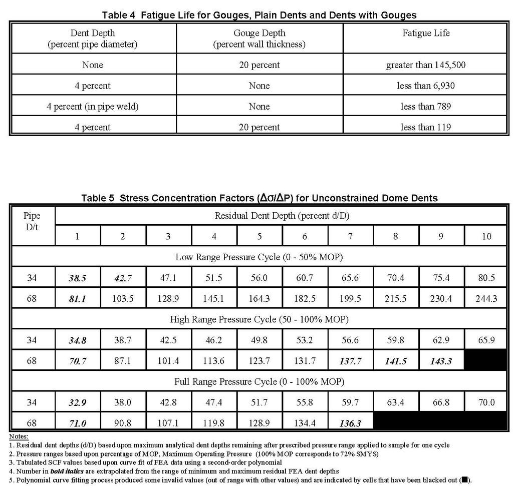
6 Wrinkle Bends Wrinkle bends are associated with the bending of pipe that result in creating local indentations along the length of the affected area. Wrinkle bends are not considered favorably by the pipeline codes and most operators. As a point of reference, ASME B (g) states that wrinkle bends are permitted only on systems that operating at hoop stress levels less than 30% of the specified minimum yield strength. As part of the American Petroleum Institute study (Alexander and Kiefner, 1997c), experimental efforts were undertaken to assess the effects of wrinkle bends on the fatigue life of pipelines. Three 36-inch x 0.81-inch pipes were fitted with wrinkle bends having nominal depths of %, 4%, and 6% (wrinkle depth percentage calculated by dividing wrinkle depth by the nominal diameter of the pipe). Figure 1 shows the pipe sample with % wrinkles, while Figure shows the corresponding profiles for the three wrinkles that were tested. Pressure cycle testing was performed where the samples were pressure cycled to 100% of the operating pressure. The following fatigue results were obtained. percent wrinkle - NO failure after 44,541 cycles 4 percent wrinkle - failure after,791 cycles 6 percent wrinkle - failure after 1,086 cycles The above results were a significant find for the API research program. The critical observations is that although depth of damage is important (wrinkle or dent), the more important factor is the profile shape of the damage. The change in radius of curvature along the length of the line is directly related to bending strains. As noted in the fatigue data, a wrinkle having a depth of 6% poses a significant threat to the integrity of the pipeline. Although intentional wrinkle bends are unlikely to occur offshore, the authors have observed several anchor impact zones that clearly resembled the damage profile associated with wrinkle bends. For this reason, any offshore damage that resembles a wrinkle bend (i.e. deect having a sharp curvature) should be removed as soon as is prudent. Summary of Experimental Work The information presented in this paper indicates that a significant level of research has been conducted world-wide in an effort to characterize and assess the severity of plain dents and dents with gouges. In can be concluded that a certain hierarchy exists in terms of defect severity, although unquestionable scatter is present in both the static and fatigue data. Empirical models and semi-empirical models have been able to predict with some success the failure pressure for dents with gouges; however, the extreme number of variables precludes the development of a general model that can accurately forecast the fatigue behavior of mechanical damage. ANALYTICAL RESEARCH EFFORTS The international attempts directed at analysis of plain dents and dents with gouges pales in comparison to the vast efforts that have been conducted experimentally. Much of the experimental investigations were initiated in the 1960s and 1970s when the use of finite elements and computer-aided software was limited; however, the 1990s have seen greater levels of analytical research because of the advances in high-speed computers. The advantage of computationally studying dents is that it is relatively simple to make variable modifications in the course of a given investigation, while full-scale testing is expensive, it prevents assessment of a single variable, and can require significant levels of time in order to generate one data point. The most comprehensive body of analytical efforts have been funded by the American Gas Association (Fowler et al., 1995), Pipeline Research Committee International (Leis, 1998), Office of Pipeline Safety (Keating, 1996) and the American Petroleum Institute (Alexander and Kiefner, 1997c). The analytical efforts have addressed areas such as the following. Rerounding behavior of dent due to elastic rebound applied pressure Effects of pipe and indenter geometry Constrained versus unconstrained dent configuration Effects of soil response Alternating stress/strain response to internal pressure differentials All of these programs incorporated insights learned experimentally in developing analytical efforts. The finite element modeling by Keating resulted in the development of strain concentration factors, although stress concentration factors were used in the report for estimating fatigue life. Keating rightly recognized the need for the development of damage factors for characterizing defects of varied configurations and proposed that the strain-based model could be used in future studies for such developments. The analytical efforts by Fowler and Alexander focused on the development and application of stress concentration factors (SCFs) in order to predict the number of cycles to failure for different dent and pipe geometries. Finite element methods were used in these analytical efforts. Because of the familiarity of the author with these research programs, discussions herein will relate to the SCFs and their use in predicting the fatigue behavior of dented pipelines developed for the American Petroleum Institute. 6
7 Finite Element Methods A detailed description of the principles associated with finite element analyses is outside the scope of this paper; however, the basic components and variables involved in the API research program are discussed. The ABAQUS (version 5.4) general-purpose finite element program was used to perform the analyses. The dimensions for the pipe models were 1.75-in outer diameters, wall thicknesses of in and in, and the lengths of the pipes were 30 inches total (approximately.5 diameters from the center of the dent). The geometry for the indenters was equivalent to those used in the API experimental work (Alexander and Kiefner, 1997c). The four basic load steps for the unconstrained smooth dents were as follows: Indent to a depth specified as a percentage of pipe diameter Remove indenter and allow elastic rebound of the pipe Apply pressure inside the pipe Remove internal pressure (determination of final residual dent depth). Seventy-two dent combinations were analyzed, although they will not all be reported in this paper. One of the primary objectives of the API research program was to provide pipeline operators with a method for predicting the number of cycles to failure for a given dent depth or defect type. The experimental results may be applied to certain defect combinations, assuming they have similar geometries and load histories as those tested. However, the benefit of having analytical results resides in the capacity to calculate fatigue lives for a variety of dent depths and pressure levels. Validation with experimental findings adds greater confidence in applying these analytical results. Provided in Table 5 are the some of the SCF tables calculated using the FEA results. The table considers the following variables, Residual dent depth Stress concentration factor Alternating pressure level. The tabulated values for each of the dent depths (e.g., 1%, %,... ) were computed using a polynomial curve fit of the FEA data. For example, at the lower pressure level, the unconstrained dome dent with a pipe D/t ratio of 68 had SCF 1 values of 10.7, 188.9, and 31.0 for residual dent depths of.8, 6.4, and 9.0, respectively. These values were used in developing the following second-order polynomial, σ d d = P D D where σ/ P represents the stress concentration factor. This procedure was done for all 7 dent cases and produced a total of 4 curves (each curve has 3 dent depths). Using these curves, the SCF values were determined for integer dent depths. As noted, some curve fits produced non-linearities which prohibited their use over the entire range of the tabulated dent depth levels. Based upon experimental data, the residual dent depths for the 1-inch pipe (D/t of 68) never exceeded 6% of the pipe s diameter when an internal pressure of 7% SMYS was applied, even with an initial indentation of 18%. For this reason, those SCF values not listed due to excessive non-linearities for the respective curve fits that were outside the range of practical application. Once the stress concentration factors and tables were developed, calculation of fatigue lives for the respective defect combinations were possible. This process was also used for validating the analytical efforts. While numerous fatigue curves could be used, the one selected was from the ASME Boiler & Pressure Vessel Code, Section VIII, Division, Appendix 5 (Figure ). This curve is for carbon steels with yield strengths less than 80 ksi. While this curve is design-oriented, it is conservative by a factor of two with respect to stress and twenty with respect to cycle number. The curve is described by the following equation, ln N = e where σ is computed by multiplying the SCF by the applied pressure range, P. Consider a dented pipe with the following characteristics: Residual Dent Depth: 3 percent of pipe diameter Pipe D/t: 68 Pressure Level psig (50% MOP) Dent Type: Unconstrained Dome Dent. For calculating the expected fatigue life for such a defect, consult Table 5 and extract the appropriate SCF which is for this problem. Using this SCF and P equal to 550 psig, the fatigue life is computed to be, σ 1 * By this definition the SCF for a pipe with D/t = 68 with no dent is 34. This is because )S = )PD/t by the Barlow formula. Thus, the relative effect of any given value of SCF calculated for a pipe with D/t = 68 by the finite element analysis can be visualized by dividing the SCF by 34. For the highest value shown in Table 5, (44.3 for a 10 percent residual dent) the relative effect is 44.3/34 or more than a factor of 7. Even for small residual dents, however, one can see that the relative SCF can be expected to result in cyclic stress ranges to 3 times as large the Barlow stress range. 7
8 ln N = e = 754, 10 cycles For the same problem, consider the pressure range to be 1,100 psig (100% MOP). The SCF is found to be and P is equal to 1,100 psig. The fatigue life is computed to be, ln N = e = 81,755 cycles This set of calculations shows the significant impact that the applied pressure range has on the fatigue life, even though there is only a 5.6 percent difference in the respective stress concentration factors. Table 6 provides a comparison of results for the experimental and analytical fatigue lives of samples UD6A- and UD1A-3 (Alexander and Kiefner, 1997c). As noted in the table, an Experimental Equivalent Number of Cycles is provided for two of the experimental dented fatigue samples. The tabulated results indicate that a reasonably accurate method of estimating fatigue life has been developed. The results are adequately close given the inherent variability in all fatigue testing and the uncertainties in predicting fatigue life, in addition to issues relating to modeling difficulties and assumptions. Effects of Buckling Capacity in a Dented Subsea Pipeline As discussed previously, the presence of dents in a pipeline likely change the ovality in a pipeline. For subsea applications, especially deepwater conditions where external pressures are large, assessing the effects of collapse should be a part of every dent evaluation. As an example, a presentation is made on prior work that involved a dent in a subsea flowline in the Gulf of Mexico at a water depth of approximately 7,000 feet. While the main purpose of the evaluation was to assess the integrity of the damage from a cyclic service standpoint, considerations were also made to determine the collapse capacity due to external pressure using finite element based limit analysis. The finite element analysis involved the following load steps. Step #1: Apply internal pressure to the inside of the pipe (4,55 psi - difference between MAOP and external pressure of 3,175 psi corresponding to 7,150 feet of sea water) Step #: Move indenter to make contact with pipe Step #3: Push indenter into pipe to a depth of 1.0 inches Step #4: Remove indenter and determine residual dent depth (found to be inches) Step #5: Remove internal pressure Step #6: Apply an internal pressure of 4,55 psi Step #7: Remove internal pressure (0 psi differential between inside and outside of pipe) Step #8: Apply external pressure of 1,700 psi to outside of sample (perform a limit analysis to determine buckling capacity of flowline considering the presence of a dent) Figure 3 shows the residual von Mises stress state that is calculated after the removal of internal pressure (corresponds to Step # 7). In addition to addressing the effects of cyclic internal pressure on the fatigue life of the flowline, SES also performed a limit analysis to determine the impact of the dent on the buckling capacity of the pipe. Figure 4 shows the deflection of the dented pipe region as a function of external pressure. A limit analysis involves the application of increasing loads (in this case external pressure) to the point where disproportionate displacements occur. The load at which this occurs is defined as the lower bound collapse load. As shown in Figure 4, once a pressure of approximately 14,000 psi is reached, the displacement increases without bound, defining this pressure as the lower bound collapse load. The external pressure at the 7,700-ft water depth (shown as the SOLID RED line in this figure) is approximately 5 percent of the 14,000 psi pressure value, indicating that a safety margin of 4 exists relative to the external pressure at which buckling is likely to occur. In other words, it is unlikely that the flowline will buckle even in the event of complete internal pressure loss at a water depth of 7,000 feet. Response of Dents to Soil Loading Although it is certain that numerous independent studies have been conducted to address the interaction of dented pipes and soil, an extensive research program has not been conducted to date. It is interesting to note that many researchers recognize the need for such a study, but no one has undertaken the effort. Briefly discussed in this section of the paper is a small-scale effort directed at assessing the effects of soil stiffness on the behavior of a dented pipeline (Alexander et al., 1998). A series of finite element models were used to address the effects of, Dent shape and depth Pressure at instant of indentation Variations in soil stiffness Effects of hydrotesting of the dent rerounding behavior. 8
9 The general observation was that the presence of soil acts to increase the effective stiffness of the pipe during the denting process, much like internal pressure. The models showed that greater dent depths could be achieved with increasing soil stiffness, representative of compacted soil around a pipeline. During the process of rerounding due to internal pressure, the residual dent depth of the dented pipe in soil was deeper than if no soil had been present. Also, the analysis showed the benefits of hydrotesting in rerounding the dent. Similar findings were found on the experimental program conducted for API by Alexander and Kiefner in that the fatigue lives of dents subjected to hydrotesting (90 percent SMYS) exceeded the fatigue lives for those dents that were not subjected to such one-time elevated stress levels. Implications of Analytical Results In this section of the paper, results from the finite element work were related to the overall API research program. First, it must be recognized that the analytical efforts were a cursory evaluation to show how one might generate and use stress concentration factors based on finite element analyses to compare the effects of dents of different sizes involving different pipe geometries. It does appear that the approach is valid and useful. However, much more work is necessary to permit the analyses to be applied extensively with a high degree of confidence. Additional comparisons with experimental results is desirable. It is likely that further comparisons would show the need to calibrate the model because neither the mechanics nor the material factors could be defined adequately by the size of effort undertaken in this project. Second, as in-line inspection technology to detect mechanical damage evolves, there will be a need to rank dent-like indications based on size and shape. An expanded and well-validated version of the SCF approach (or strain-based approach) developed herein could serve as the basis for dent-ranking guidelines just as the B31G criterion now does for corrosion-caused metal loss anomalies. SYSTEMATIC METHODS FOR DEFECT ASSESSMENT Over the past several years the authors have been called on numerous occasions to help pipeline operators assess the severity of pipeline damage and determine the best course of action for resuming service. There is a significant range of information in terms of quality that is provided when the request for service is made by an operator. Consider the following two examples. A pipeline company had a line that was apparently impact by an anchor in the relatively shallow waters of an inlet. The only information that was provided was a sonar scan of the displaced pipeline and details on the geometry of the pipeline and its operating pressure along with cyclic pressure service conditions. A pipeline was impacted with multiple anchors based on observations of the displaced line. A sonar scan along with a ROV run was made that included detailed video along the route of the line. The operator was also able to provide survey data on the displaced position of the line relative to the original position using MMS as-laid data. The operator was also able to provide geometry on several sections of the damaged pipeline that permitted the construction of local finite element models. What is apparent in studying the information in the above case studies is the range of information that is available at the time of an assessment. It is certainly a challenge to provide a useful assessment when limited information is available; however, it is possible to use several tools to make important decisions about mechanical integrity with sparse data. The sections below provide methods and procedures that can be used to assess the integrity of damaged pipelines. Using Lateral Displacement Data Even when operators are not able to provide detailed information and measurements of dents, more often than not it is possible to get an idea of lateral pipeline displacement from either sonar scans (typically lower resolution data) or survey measurements using a ROV (potentially better resolution). The displaced data can be used in several ways that include the following. Finite Element Model. Finite element analysis (FEA) can be used to provide information about tensile and being strains in a displaced pipeline. In terms of displacement pipeline assessments, FEA beam elements are used to simulate the displaced pipeline and can integrate such variables as internal pressure and temperature. The change in strain is computed by modeling the pipeline in the as-laid condition and then displacing the appropriate section of pipe the prescribed lateral distance. The soil is modeled using spring elements that provide lateral displacement. From the analysis it is possible to compute the force required to displace the pipeline. Figure 5 is a plot from a FEA model showing the displaced position of a pipeline. From this model strains were computed. First Principle Bending Strain Calculations. While it is not also possible or practical to construct a detailed finite element model of a damaged pipeline; it is possible to calculate bending strains based on the changing radius of curvature in a laterally displaced pipeline. Using a series of mathematic expressions to calculate radius of curvature, the estimate bending strain is calculated. Figure 6 provides a schematic showing the method for performing this type of assessment (equations based on law of sin and cosine). The authors highly recommend that this assessment method be performed once displacement data is available. An EXCEL spreadsheet can be programmed to accept the mathematical expressions that will permit the radius of curvature to be calculated as a function of axial position along the length of the line. Figure 7 is a plot that shows bending strain as a function of axial position along the line. What is impressive about this approach is that although its accuracy is somewhat limited, it provides an excellent first pass assessment of areas of the pipeline where elevated bending strains are likely to exist. Before any detailed investigations are performed, this method should be used to provide an overall assessment of damage to the pipeline. 9
10 Using Dent Profile Data The greatest level of accuracy is achieved in assessing the severity of dented pipelines when inspection efforts determine the profile of the damaged section of pipe. Once this information is obtained, it is possible to perform a finite element analysis of the damaged area using elastic-plastic material properties to capture the residual stress state of the pipe. Cyclic pressure can be modeled in an effort to estimate the alternating stress in the damaged section of pipe. Provided below are steps involved in a example dent analysis using finite element methods. 1. Apply internal pressure of 1,06 psi to pipe (MAOP). Move indenter vertically down into pipe 4.5 inches 3. Remove indenter to obtain residual dent (analysis resulted in depth of 1.5 inches) 4. Remove internal pressure 5. Re-apply internal pressure of 1,06 psi Figure 8 shows the basic layout for the finite element model used to calculate local stress concentrations and Figure 9 contains several contour plots from the FEA model including Steps #1,, and 3. Assuming that shakedown to elastic action has occurred between Step #4 and #5 (condition at which no appreciable deformation of the dent is likely with continued pressure cycling), the alternating stress associated with MAOP can be calculated. This value can then be used as input into a fatigue curve to estimate remaining life associated with cyclic service conditions. It is the authors observations that the vast majority of offshore pipeline damage may be described as plain dents. For this reason, the fatigue life is often governed by the alternating stress due to cyclic service (which is a function of dent geometry) and the cycles to failure for the respective fatigue curve. Interested readers are encouraged to review the discussions presented previously in the Finite Element Methods section of this paper. Integrating Experimental Data A significant body of data has been presented in previous sections of this paper. When called upon to perform defect assessments, the authors frequently draw from insights gained by previous research efforts. If the body of data is sufficiently large, it is possible for assessment efforts to compare the geometry for a particular defect from an existing data point within the research data. Knowing the performance of the research data points under specific service conditions (e.g. static and/or cyclic pressure), the future performance of the damaged pipeline can be estimated, Greater accuracy in this effort is achieved when more information is known about both the research and actual damage. Examples include material properties (including toughness) cyclic pressure history, and geometry of the pipeline damage in the form of dent profile. SUGGESTED ASSESSMENT METHOD One of the primary purposes of this paper is to suggest for the pipeline industry a systematic approach for assessing defect severity. When done properly, it is possible to integrate important information such as survey data for a displaced pipeline and ROV videos showing images of damaged sections of a pipeline. Provided in Figure 10 is a flow chart that provides elements of a proposed process for integration of information into a pipeline damage assessment. The following steps are included in this effort. 1. Detect damaged section of pipe (usually via in-line inspection methods or using a ROV). Assess the severity 3. Determine acceptability by ranking relative severity if multiple defects exist 4. Repair or remove the damaged section of pipeline 5. Restore service including hydrotesting required 6. Put line back in service and continue operation CONCLUSIONS The paper has provided a wide array of information on research efforts associated with studies on damaged pipelines. One of the great challenges in presenting such an extensive body of data is the potential for overwhelming the reader. While this was certainly not the intent of the authors, it is important to recognize that some form of research has likely been completed on every form of damaged pipeline imaginable. One of the great challenges for research is getting key findings of research efforts into the hands of those who can use them the most. To a certain extent, that has been the aim of this paper. By implementing the proposed methods included in this paper, operators can invoke a systematic process for assessing defect severity. Even applying the six step process outlined in Figure 10 is a good starting point. Another important consideration is that once damage has been detected, operators are encouraged to start collecting and cataloguing information as soon as possible. It has been the authors observation that when this done, the likelihood for performing a successful damage assessment is greatly increased. 10
11 REFERENCES (1) Alexander, C.R., (October 006), "Assessing the Effects of External Damage on Subsea Pipelines," Paper No. IOPF , Proceedings of the ASME International Offshore Pipeline Forum, October 4-5, 006, Houston, Texas. () Alexander, C. R., Kiefner, J. F., and J. R. Fowler, Repair of Dents Combined with Gouges Considering Cyclic Pressure Loading, 8th Annual International Energy Week Conference and Exhibition, Houston, Texas, January (3) Alexander, C. R., Fowler, J, R., and K. Leewis, Analysis of Composite Repair Methods for Pipeline Mechanical Damage Subjected to Cyclic Pressure Loads, 8th Annual International Energy Week Conference and Exhibition, Houston, Texas, January (4) Alexander, C. R. and J. F. Kiefner, Effects of Smooth and Rock Dents on Liquid Petroleum Pipelines, API Publication 1156 (First Edition), American Petroleum Institute, Washington, D.C., November (5) Alexander, C. R. and L. M. Connelly, Analytical Recreation of a Dent Profile Considering Varied Soil, Operating and Boundary Conditions, 1998 Energy Sources Technology Conference & Exhibition, Sheraton Astrodome Hotel, Houston, Texas, February -4, Alexander, C. R. and F. D. Wilson, Development and Testing of the Armor Plate Pipeline Repair System, 1999 Energy Sources Technology Conference & Exhibition, Sheraton Astrodome Hotel, Houston, Texas, February 1-3, (6) Alexander, C. R., Analysis of Dented Pipeline Considering Constrained and Unconstrained Dent Configurations, 1999 Energy Sources Technology Conference & Exhibition, Sheraton Astrodome Hotel, Houston, Texas, February 1-3, (7) American Society of Mechanical Engineers, Manual for Determining the Remaining Strength of Corroded Pipelines, ASME B31G- 1991, New York, New York, 1991 edition. (8) American Society of Mechanical Engineers, Liquid Transportation System for Hydrocarbons, Liquid Petroleum Gas, Anhydrous Ammonia and Alcohols, ASME B31.4, New York, New York, 199 edition. (9) American Society of Mechanical Engineers, Gas Transmission and Distribution Piping Systems, ASME B31.8, New York, New York, 1995 edition (10) Corder, I. and P. Corbin, The Resistance of Buried Pressurized Pipelines to Outside Force Damage, Paper No. 4, EPRG/PRC Eighth Biennial Joint Technical Meeting on Line Pipe Research, Paris, France, May 14-17, (11) Eiber, R. J., and B. N. Leis, Line Pipe Resistance to Outside Force, Paper No. 14, EPRG/PRC Tenth Biennial Joint Technical Meeting on Line Pipe Research, Cambridge, April 18-1, (1) Fowler, J. R., C. R. Alexander, P.J. Kovach, and L.M. Connelly, Cyclic Pressure Fatigue Life of Pipelines with Plain Dents, Dents with Gouges, and Dents with Welds, Prepared by Stress Engineering Services for the Offshore and Onshore Applications Supervisory Committee of the Pipeline Research Committee, PR , June (13) Hopkins, P., Jones D. G. and A. J. Clyne, Significance of Dents and Defects in Transmission Pipelines, Proceedings of the International Conference on Pipework Engineering And Operations, London, UK, February 1-, (14) Hopkins, P., The Significance of Mechanical Damage in Gas Transmission Pipelines, Paper No. 5, EPRG/PRC Eighth Biennial Joint Technical Meeting on Line Pipe Research, Paris, France, May 14-17, (15) Jones, D. G. and P. Hopkins, Influence of Mechanical Damage on Transmission Pipeline Integrity, Proceedings of the 1983 International Gas Research Conference, London, UK, June 13-16, (16) Keating, P. B. and R. L. Hoffman, Fatigue Behavior of Dented Petroleum Pipelines (Task 4), Office to the Office of Pipeline Safety, U. S. Department of Transportation, Texas A&M University, May (17) Kiefner, J. F., W. A. Bruce, and D. R. Stephens, Pipeline Repair Manual, Prepared for the Line Pipe Research Supervisory Committee of the Pipeline Research Committee, (18) Kiefner, J. F., C. R. Alexander, and J. R. Fowler, Repair of Dents Containing Minor Scratches, Proceedings from Ninth Symposium on Pipeline Research, Houston, Texas, October, (19) Maxey, W.A., Outside Force Defect Behavior, NG-18 Report No. 16, A.G.A. Catalog No. L51518, (0) Rosenfeld, M. J. Investigations of Dent Rerounding Behavior, Proceedings of the International Pipeline Conference, Vol. 1, pages , Calgary, Canada,
 Figure Wrinkle profile for the three test")
12 Figure 1 Photo of 36-inch diameter pipe with % wrinkles PROFILE MEASUREMENTS OF WRINKLES AFTER COMPLETION OF APPLIED CYCLES Depth after cycling (inches) Sample Configuration percent buckle 4 percent buckle 6 percent buckle Longitudinal Position (inches) Figure Wrinkle profile for the three test samples 1
 External Pressure versus Displacement External pressure of 1,700 psi applied to finite element model 14000 1000 External Pressure (psi) 10000 8000 6000 4000 000 External pressure of 3,175 psi")
13 Figure 3 - Von Mises stress after internal pressure removed (residual stress state) (Magnification factor on displacement of.4) External Pressure versus Displacement External pressure of 1,700 psi applied to finite element model External Pressure (psi) External pressure of 3,175 psi (7,150 fsw) Vertical Dent Displacement (inches) Figure 4 - Response of dented pipe to elevated external pressures 13
14 14 Figure 5 Finite element model showing displaced position of pipeline Figure 6 Calculating bending strain using first principles (t in the above formulation is the outer radius of the pipe) 1 1 ) ( ) ( y y x x a + = 3 3 ) ( ) ( y y x x b + = ) ( ) ( y y x x c + = ab c b a q + = 1 q c R = R t = ε a b c R 1 3 X Y Nodal points a b c R 1 3 X Y Nodal points r X Y R r t Nomenclature e Bending strain t Thickness of beam r Radius of curvature (centerline) R Radius of mandrel t = R + ρ
15 Strain as a Function of Position Along Pipeline Bending Strain based on Curvature (percent) Pipeline Position Measured from Southwest (feet) Figure 7 Bending strain as a function of position calculated using curvature Analysis Steps: Indenter (1 long with 3 radius ends) 1. Apply an internal pressure of 50% SMYS. Indent pipe with indenter to desired depth (and force) 3. Remove indenter (to achieve residual dent depth) 4. Remove pressure 5. (Typically) Calculate alternating stress to determine design fatigue life Figure 8 Methods for assessing dent damage using finite element methods 15
16 Step #1 Installation of dent Step # Removal of indenter Strains exceeding 1 percent plotted in RED Maximum strain in dent approximately 1 percent Step #3 Removal of internal pressure Figure 9 Strain associated with different steps in the indentation process Detection Finding the defects (inspection technology) Characterization Assessing the severity (experience, operating history, testing, analysis, and research) Determination Defining acceptability (rank defects if required) (evaluation relative to codes, standards, and government regulations) Repair (if appropriate) Repairing the damage (if required) (use available technology to determine the best repair options) Restore Service Continue operation (restore service once integrity has been reestablished) Figure 10 Steps involved in the defect assessment process 16
17 17
18 18
Evaluating Damage to Onshore and Offshore Pipelines Using Data Acquired Using In-line Inspection Efforts
 Evaluating Damage to Onshore and Offshore Pipelines Using Data Acquired Using In-line Inspection Efforts Dr. Chris Alexander Stress Engineering Services, Inc. chris.alexander@stress.com EXECUTIVE SUMMARY
ASSESSMENT AND ANALYSIS OF PIPELINE BUCKLES
 ASSESSMENT AND ANALYSIS OF PIPELINE BUCKLES GE Oil & Gas PII Pipeline Solutions Inessa Yablonskikh Principal Consultant Aberdeen, November, 14 th 2007 Assessment And Analysis Of Pipeline Buckles Introduction
Kiefner & Associates, Inc.
 Kiefner & Associates, Inc. KAPA FAQs What does KAPA stand for? KAPA is an acronym for Kiefner & Associates Pipe Assessment. What does KAPA do? KAPA calculates an estimated failure pressure of a pipe affected
The Use of ILI In Dent Assessments
 The Use of ILI In Dent Assessments Prepared for: 2014 CRUG Conference Date: 11 September 2014 Prepared by: Rhett Dotson, PE Contributions from Dr. Chris Alexander and Markus Ginten Contents Current Dent
UKOPA Dent Management Strategy
 UKOPA Dent Management Strategy 1 Background Pipelines are thin shell structures which are susceptible to geometric distortions and dents during handling, construction, and operation. These dents and distortions,
Enbridge Pipelines Inc. PIPELINE INTEGRITY AXIAL CRACK THREAT ASSESSMENT
 Enbridge Pipelines Inc. Line 9B Reversal and Line 9 Capacity Expansion Project Appendix A to Updated Pipeline Engineering Assessment PIPELINE INTEGRITY AXIAL CRACK THREAT ASSESSMENT Table of Contents 1.
FINAL REPORT. TTO Number 10 Integrity Management Program Delivery Order DTRS56-02-D Dent Study
 Department of Transportation Research and Special Programs Administration Office of Pipeline Safety TTO Number 10 Integrity Management Program Delivery Order DTRS56-0-D-70036 Dent Study FINAL REPORT Submitted
CONVECTION SECTION FAILURE ANALYSIS AND FITNESS-FOR-SERVICE ASSESSMENT
 ASSET INTEGRITY INTELLIGENCE CONVECTION SECTION FAILURE ANALYSIS AND FITNESS-FOR-SERVICE ASSESSMENT JAMES R. WIDRIG, Manager Advanced Engineering at Quest Integrity Group VOLUME 23, ISSUE 6 NOVEMBER DECEMBER
GAINS WITH ADVANCED DATA ASSESSMENT IN ILI: LEVERAGING PIPELINE DATA WITH EXPERTISE TO ELIMINATE RISK, PRIORITIZE AND SCHEDULE
 GAINS WITH ADVANCED DATA ASSESSMENT IN ILI: LEVERAGING PIPELINE DATA WITH EXPERTISE TO ELIMINATE RISK, PRIORITIZE AND SCHEDULE NECESSARY REPAIRS For traditional in-line inspection (ILI) vendors, considering
LIMIT STATE DESIGN BASED ON EXPERIMENTAL METHODS FOR HIGH PRESSURE SUBSEA PIPELINE DESIGN
 Proceedings of Conference ASME International Offshore Pipeline Forum October 28-29, 2009, Houston, Texas USA LIMIT STATE ESIGN BASE ON EXPERIMENTAL METHOS FOR HIGH PRESSURE SUBSEA PIPELINE ESIGN Chris
Dent behaviour of steel pipes under pressure load
 University of Windsor Scholarship at UWindsor Electronic Theses and Dissertations Winter 214 Dent behaviour of steel pipes under pressure load Jandark Oshana Jajo University of Windsor Follow this and
A FINITE ELEMENT PROCEDURE TO MODEL THE EFFECT OF HYDROSTATIC TESTING ON SUBSEQUENT FATIGUE CRACK GROWTH
 Proceedings of the International Pipeline Conference & Exposition IPC216 September 26-3, 216, Calgary, Alberta, Canada IPC216-64563 A FINITE ELEMENT PROCEDURE TO MODEL THE EFFECT OF HYDROSTATIC TESTING
NASA AEROSPACE PRESSURE VESSEL SAFETY STANDARD
 NSS/HP-1740.1 This Standard was CANCELLED on Jul 30 2002 22 FEBRUARY 1974 NASA AEROSPACE PRESSURE VESSEL SAFETY STANDARD OFFICE OF SAFETY AND RELIABILITY AND QUALITY ASSURANCE NATIONAL AERONAUTICS AND
Study to Establish Relations for the Relative Strength of API 650 Cone Roof Roof-to-Shell and Shell-to- Bottom Joints
 Thunderhead Engineering Consultants I N C O R P O R A T E D 1006 Poyntz Ave. Manhattan, KS 66502-5459 785-770-8511 www. thunderheadeng.com Study to Establish Relations for the Relative Strength of API
IGEM/TD/1. Background, Development, Changes J V Haswell
 IGEM/TD/1 Background, Development, Changes J V Haswell TD/1 Background Development, Changes Technical and Safety Philosophy History of Development Key Code Requirements:- Rou?ng, BPDs Design parameters
Proceedings of the ASME th International Conference on Ocean, Offshore and Arctic Engineering OMAE2011
 Proceedings of the ASME 2011 30th International Conference on Ocean, Offshore and Arctic Engineering OMAE2011 June 19-24, 2011, Rotterdam, The Netherlands Proceedings of the ASME 2011 30th International
Technology. 38 JUL-SEPT 2010 Visit our websites at /
 Technology Burst Test, Finite Element Analysis and Structural Integrity of Pipeline System By Nasir Shafiq, Mokhtar Che Ismail, Chanyalew Taye, Saravanan K and M F Nuruddin Abstract Pipelines are one of
Fitness for Service Assessment of Ageing Pressure Vessel Experiencing External Corrosion: A Case Study
 The International Journal Of Engineering And Science (IJES) Volume 6 Issue 2 Pages PP 12-16 2017 ISSN (e): 2319 1813 ISSN (p): 2319 1805 Fitness for Service Assessment of Ageing Pressure Vessel Experiencing
P-04 Stainless Steel Corrugated Hoses and Metal Bellows Expansion Joints
 Guideline No.P-04 (201510) P-04 Stainless Steel Corrugated Hoses and Metal Bellows Expansion Joints Issued date: 20 th October 2015 China Classification Society Foreword This Guideline is a part of CCS
Anomaly Evaluation, Response, and Repair Summit. Presentation by INGAA June 3, 2008
 Anomaly Evaluation, Response, and Repair Summit Presentation by INGAA June 3, 2008 Context of Today s Meeting Basis for Anomaly evaluation and response has become an issue on: Enforcement Integrity Management
BEFORE THE UNITED STATES DEPARTMENT OF TRANSPORTATION PIPELINE AND HAZARDOUS MATERIALS SAFETY ADMINISTRATION WASHINGTON, D.C.
 BEFORE THE UNITED STATES DEPARTMENT OF TRANSPORTATION PIPELINE AND HAZARDOUS MATERIALS SAFETY ADMINISTRATION WASHINGTON, D.C. Pipeline Safety: Meeting of Gas Pipeline Safety Advisory Committee Docket Nos.
49 CFR 195 Transportation of Hazardous Liquids by Pipeline THIS DOCUMENT CONTAINS ONLY THE SECTIONS NEEDED FOR THE API 1169 ICP EXAMS
 49 CFR 195 Transportation of Hazardous Liquids by Pipeline THIS DOCUMENT CONTAINS ONLY THE SECTIONS NEEDED FOR THE API 1169 ICP EXAMS Subpart D Construction 195.200 Scope. This subpart prescribes minimum
USING A PROBABILITY APPROACH TO RANK IN-LINE INSPECTION ANOMALIES FOR EXCAVATION AND FOR SETTING REINSPECTION INTERVALS
 USING A PROBABILITY APPROACH TO RANK IN-LINE INSPECTION ANOMALIES FOR EXCAVATION AND FOR SETTING REINSPECTION INTERVALS by Dennis C. Johnston and Carolyn E. Kolovich Kiefner & Associates, Inc. P.O. Box
MAE 322 Machine Design Lecture 5 Fatigue - 2. Dr. Hodge Jenkins Mercer University
 MAE 322 Machine Design Lecture 5 Fatigue - 2 Dr. Hodge Jenkins Mercer University Returning to Stress-Life Fatigue Modeling Fatigue Stress-Life: S f -N Diagram for steels Stress levels below S e (Endurance
B31.3 Piping Checklist and Rules of Thumb March 1, 2008 Program Version Paulin Research Group s
 Paulin Research Group s PRG B31.3 Piping Checklist and Rules of Thumb Program User Guidelines Contents 1.0 Program Objective 2.0 Summary 3.0 Getting Started 4.0 Main Topics Addressed 5.0 Report Discussion
ASPIRE for Integrity Management Support for Upstream Assets. Payam Jamshidi, TWI Ltd Sebastian Hartmann, Innospection Ltd
 ASPIRE for Integrity Management Support for Upstream Assets Payam Jamshidi, TWI Ltd Sebastian Hartmann, Innospection Ltd OVERVIEW - Discussion of corroded pipe assessment procedures under combined loading
2003 WJTA American Waterjet Conference August 17-19, 2003 Houston, Texas Paper PIPE THREADS-WHAT IS THE LIMIT?
 23 WJTA American Waterjet Conference August 17-19, 23 Houston, Texas Paper PIPE THREADS-WHAT IS THE LIMIT? D. Wright, J. Wolgamott, G. Zink StoneAge, Inc. Durango, Colorado, U.S.A. ABSTRACT At present
Presented to the Israel Annual Conference on Aerospace Sciences, 2009 RISK-ANALYSIS A SUPPLEMENT TO DAMAGE-TOLERANCE ANALYSIS
 RISK-ANALYSIS A SUPPLEMENT TO DAMAGE-TOLERANCE ANALYSIS Abraham Brot Engineering Division Israel Aerospace Industries Ben-Gurion Airport, Israel abrot@iai.co.il ABSTRACT Risk-analysis, based on probabilistic
Subpart E. Pressure Testing
 Subpart E Pressure Testing 195.300 Scope This subpart prescribes minimum requirements for pressure testing of steel pipelines. However, this subpart does not apply to movement of pipe covered by 195.424.
STANDARD SPECIFICATION FOR SPLIT TEES (HOT TAP MATERIAL)
") STANDARD SPECIFICATION FOR SPLIT TEES (HOT TAP MATERIAL) TEE (HOT TAPPING MATERIAL) S-04-02-040 Page 1 of 7 1.0 SCOPE This specification covers the basic requirements for the design, manufacture and supply
STANDARD SPECIFICATION FOR SPLIT TEES (HOT TAP MATERIAL) TEE (HOT TAPPING MATERIAL) S-04-02-040 Page 1 of 7 1.0 SCOPE This specification covers the basic requirements for the design, manufacture and supply
INTRODUCTION TABLE OF CONTENTS
 2 INTRODUCTION Thank you for choosing Servometer to design and manufacture your unique, new electrodeposited bellows for your particular application. The definitions, formulas and design parameters inside
INTEGRITY MANAGEMENT OF STRESS CORROSION CRACKING IN GAS PIPELINE HIGH CONSEQUENCE AREAS
 Designator: Meta Bold 24/26 Revision Note: Meta Black 14/16 INTEGRITY MANAGEMENT OF STRESS CORROSION CRACKING IN GAS PIPELINE HIGH CONSEQUENCE AREAS Date of Issuance: October 31, 2008 This report was prepared
Calibration and Validation of the Shell Fatigue Model Using AC10 and AC14 Dense Graded Hot Mix Asphalt Fatigue Laboratory Data
 Article Calibration and Validation of the Shell Fatigue Model Using AC10 and AC14 Dense Graded Hot Mix Asphalt Fatigue Laboratory Data Mofreh Saleh University of Canterbury, Private Bag 4800, Christchurch,
EXPERIMENTAL RESULTS OF GUIDED WAVE TRAVEL TIME TOMOGRAPHY
 18 th World Conference on Non destructive Testing, 16-20 April 2012, Durban, South Africa EXPERIMENTAL RESULTS OF GUIDED WAVE TRAVEL TIME TOMOGRAPHY Arno VOLKER 1 and Hendrik VOS 1 TNO, Stieltjesweg 1,
Gerald D. Anderson. Education Technical Specialist
 Gerald D. Anderson Education Technical Specialist The factors which influence selection of equipment for a liquid level control loop interact significantly. Analyses of these factors and their interactions
Contents. 1. Non Destructive Testing Requirements. 2. Non Destructive Testing Methods Magnetic Particle Examination
 1 Contents 1. Non Destructive Testing Requirements 2. Non Destructive Testing Methods Magnetic Particle Examination 3. Non Destructive Testing Methods Dye Penetrant Examination 4. Non Destructive Testing
FEA ANALYSIS OF PRESSURE VESSEL WITHDIFFERENT TYPE OF END CONNECTIONS
 FEA ANALYSIS OF PRESSURE VESSEL WITHDIFFERENT TYPE OF END CONNECTIONS Deval Nitin Bhinde 1 and Rajanarsimha S. 2 1 MTech CAD-CAM & Robotics, 2 Facculty, Department of Mechanical Engineering K.J. Somaiya
Other Si min/max. Cr min/max. 0.4/ / / / Bal.
 178.46 Specification 3AL seamless aluminum cylinders. (a) Size and service pressure. A DOT 3AL cylinder is a seamless aluminum cylinder with a imum water capacity of 1000 pounds and minimum service pressure
2.1 Introduction to pressure vessels
 2.1 Introduction to pressure vessels Pressure vessels in the form of cylinders and tanks are used for storing variety of liquids and gasses at different temperatures and pressures. Some of the substances
Offshore platforms survivability to underwater explosions: part I
 Computational Ballistics III 123 Offshore platforms survivability to underwater explosions: part I A. A. Motta 1, E. A. P. Silva 2, N. F. F. Ebecken 2 & T. A. Netto 2 1 Brazilian Navy Research Institute,
NATURAL GAS MAINTENANCE. Part 192 Subpart "M"
 NATURAL GAS MAINTENANCE Part 192 Subpart "M" CONTACT INFORMATION Pamela West Pipeline Safety Specialist U.S. Department of Transportation PHMSA Inspector Training and Qualifications Main: (405) 686-2310
Stress Analysis of The West -East gas pipeline with Defects Under Thermal Load
 Stress Analysis of The West -East gas pipeline with Defects Under Thermal Load Abstract Xu Lei School of Petroleum Engineering, Yangtze University, Wuhan 430000, China 13071247220@163.com Natural gas is
FEA case Study: Rubber expansion joint for piping systems
 FEA case Study: Rubber expansion joint for piping systems Introduction The FEA Toolbox of Taniq makes it possible to simulate the behavior of a pipe expansion joint accurately under several load cases.
POWER Quantifying Correction Curve Uncertainty Through Empirical Methods
 Proceedings of the ASME 2014 Power Conference POWER2014 July 28-31, 2014, Baltimore, Maryland, USA POWER2014-32187 Quantifying Correction Curve Uncertainty Through Empirical Methods ABSTRACT Christopher
Elastic-Plastic Finite Element Analysis for Zhongwei--guiyang Natural Gas Pipeline Endangered by Collapse
 Abstract Elastic-Plastic Finite Element Analysis for Zhongwei--guiyang Natural Gas Pipeline Endangered by Collapse Gengxin Wu,Peng Zhang,Zhixiang Li,Zunhai Ke,Guizhi Li,Anmin Jiang 2 School of Civil Engineering
Analysis of Shear Lag in Steel Angle Connectors
 University of New Hampshire University of New Hampshire Scholars' Repository Honors Theses and Capstones Student Scholarship Spring 2013 Analysis of Shear Lag in Steel Angle Connectors Benjamin Sawyer
Overview Assessment of the 16 Inch Diameter Olympic Pipeline Integrity
 Report on Overview Assessment of the 16 Inch Diameter Olympic Pipeline Integrity to City-County Pipeline Safety Consortium of Washington November, 2001 by Bob Eiber Robert J. Eiber, Consultant Inc. 4062
Application of Expansive Soil Geotechnical Procedures
 Application of Expansive Soil Geotechnical Procedures FPA PRESENTATION John T. Bryant, Ph.D., P.G., P.E with Robert L. Lytton, Ph.D., PE. And Mr. Dean Read HOUSTON, TEXAS WEDNESDAY DECEMBER 10, 2008 2008
Liquefied gas cargo tanks and process pressure vessels
 .1 -.3 Liquefied gas cargo tanks and process pressure vessels.1 General.1.1 The present texts give the general principles which are applied by Classification Societies for approval and survey of the relevant
Engineering Practice on Ice Propeller Strength Assessment Based on IACS Polar Ice Rule URI3
 10th International Symposium on Practical Design of Ships and Other Floating Structures Houston, Texas, United States of America 2007 American Bureau of Shipping Engineering Practice on Ice Propeller Strength
Hydrostatic Testing of In-Situ Pipelines & Spike Testing. Colin Silla, PE, PMP Southeast District Manager 6/27/18
 Hydrostatic Testing of In-Situ Pipelines & Spike Testing Colin Silla, PE, PMP Southeast District Manager 6/27/18 Hydrotest Design and Support: Statistics Piping and Test Heads Overall: GTS has designed
Learn more at
 Full scale model tests of a steel catenary riser C. Bridge 1, H. Howells 1, N. Toy 2, G. Parke 2, R. Woods 2 1 2H Offshore Engineering Ltd, Woking, Surrey, UK 2 School of Engineering, University of Surrey,
Offshore engineering science
 Offshore engineering science In this research stream theoretical models advanced geotechnical models and new numerical techniques were used in applied offshore engineering topics such as loading, design
Bottom End-Closure Design Optimization of DOT-39 Non-Refillable Refrigerant Cylinders
 Y. Kisioglu a) Department of Mechanical Education, Kocaeli University, Izmit, Kocaeli, 41100, Turkey J. R. Brevick Industrial and Systems Engineering, The Ohio State University, Columbus, Ohio G. L. Kinzel
Global Buckling Design for Flexible Flowlines
 Global Buckling Design for Flexible Flowlines Challenges, Approach and Lessons Learned Mostafa Tantawi 1 Agenda Background to flexible lines Mechanical behavior of Flexible vs Steel. Why flexible buckling
STRIDE PROJECT Steel Risers in Deepwater Environments Achievements
 STRIDE PROJECT Steel Risers in Deepwater Environments Achievements 1999-21 Neil Willis Principal Engineer 2H Offshore Engineering 6 th Annual Deepwater Technologies and Developments Conference 21 The presentation
INTERNAL AXIAL CORROSION IN OFFSHORE PIPELINES: INSPECTION AND ASSESSMENT. By: Dr. Christoph Jäger, Abdullahi Atto, NDT Global, Germany
 INTERNAL AXIAL CORROSION IN OFFSHORE PIPELINES: INSPECTION AND ASSESSMENT By: Dr. Christoph Jäger, Abdullahi Atto, NDT Global, Germany Abstract Internal long axial corrosion is the most common corrosion
Stress evaluation of a bicycle crank arm connection using BEM
 Stress evaluation of a bicycle crank arm connection using BEM C. J. Hoff, R. E. Dippery & 3. Knapp Department of Mechanical Engineering Kettering University, USA Abstract An interesting problem encountered
Fatigue Life Evaluation of Cross Tubes of Helicopter Skid Landing Gear System
 IJSRD - International Journal for Scientific Research & Development Vol. 3, Issue 04, 2015 ISSN (online): 2321-0613 Fatigue Life Evaluation of Cross Tubes of Helicopter Skid Landing Gear System Madhu S
Presented to the International Technical Rescue Symposium, November Abstract
 Presented to the International Technical Rescue Symposium, November 21 Presented by: Chuck Weber, PMI Quality Manager Abstract This paper presents the results of 162 individual drop tests performed at
PIP PNE00012 Piping Examination and Leak Test Guide
 October 2017 Piping PIP PNE00012 Piping Examination and Leak Test Guide PURPOSE AND USE OF PROCESS INDUSTRY PRACTICES In an effort to minimize the cost of process industry facilities, this Practice has
Flow transients in multiphase pipelines
 Flow transients in multiphase pipelines David Wiszniewski School of Mechanical Engineering, University of Western Australia Prof. Ole Jørgen Nydal Multiphase Flow Laboratory, Norwegian University of Science
OPENINGS AND REINFORCEMENTS 26
 ASME BPVC.VIII.1-2015 UG-35.2 UG-36 (4) It is recognized that it is impractical to write requirements to cover the multiplicity of devices used for quick access, or to prevent negligent operation or the
RIGID RISERS FOR TANKER FPSOs
 RIGID RISERS FOR TANKER FPSOs Stephen A. Hatton 2H Offshore Engineering Ltd. SUMMARY Recent development work on the subject of dynamic rigid (steel pipe) risers demonstrates that their scope of application
A Traffic Operations Method for Assessing Automobile and Bicycle Shared Roadways
 A Traffic Operations Method for Assessing Automobile and Bicycle Shared Roadways A Thesis Proposal By James A. Robertson Submitted to the Office of Graduate Studies Texas A&M University in partial fulfillment
Technical Brief - Wave Uprush Analysis Island Harbour Club, Gananoque, Ontario
 Technical Brief - Wave Uprush Analysis RIGGS ENGINEERING LTD. 1240 Commissioners Road West Suite 205 London, Ontario N6K 1C7 October 31, 2014 Table of Contents Section Page Table of Contents... i List
I. CHEM. E. SYMPOSIUM SERIES NO. 85
 FIRE SURVIVAL OF PROCESS VESSELS CONTAINING GAS J. Nylund * The present work is a theoretical evaluation of the ability of process vessels to survive hydrocarbon fires when the vessels are designed and
Autodesk Moldflow Communicator Process settings
 Autodesk Moldflow Communicator 212 Process settings Revision 1, 3 March 211. Contents Chapter 1 Process settings....................................... 1 Profiles.................................................
Item ID: Rev.: 00 Status: Final Effective Date: 29-Feb-2015 EXECUTIVE SUMMARY
 EXECUTIVE SUMMARY The objective of this report is to demonstrate that sections of pipeline between MLV 401 and MLV 402 on the Canadian Mainline Line 400-2 meet the applicable requirements in CSA Z662-15
Lifecycle Performance of Escape Systems
 Lifecycle Performance of Escape Systems A look at laboratory vs field conditioning of aramid fiber based escape systems. By James Hunter, Cedric Smith, Ole Kils and Tyler Mayer for ITRS 2018 1.1 Introduction
APPLYING VARIABLE SPEED PRESSURE LIMITING CONTROL DRIVER FIRE PUMPS. SEC Project No
 APPLYING VARIABLE SPEED PRESSURE LIMITING CONTROL DRIVER FIRE PUMPS SEC Project No. 1803007-000 November 20, 2006 TABLE OF CONTENTS I. ABSTRACT...1 II. INTRODUCTION...1 III. HISTORY...2 IV. VARIABLE SPEED
Rotary air valves used for material feed and explosion protection are required to meet the criteria of NFPA 69 (2014)
") Rotary air valves used for material feed and explosion protection are required to meet the criteria of NFPA 69 (2014) 12.2.4.2. 12.2.4.2 rotary valve design criteria (close clearance) 12.2.4.3 THE DESIGN
Rotary air valves used for material feed and explosion protection are required to meet the criteria of NFPA 69 (2014) 12.2.4.2. 12.2.4.2 rotary valve design criteria (close clearance) 12.2.4.3 THE DESIGN
Flexible Spools Solution at Hybrid Risers Base A. Karnikian, Total and S. Tarbadar, M. Bonnissel, S. Legeay, Technip France
 DOT-2014 Flexible Spools Solution at Hybrid Risers Base A. Karnikian, Total and S. Tarbadar, M. Bonnissel, S. Legeay, Technip France Copyright 2014, Deep Offshore Technology International This paper was
DGZfP-Proceedings BB 90-CD Lecture 4 EWGAE 2004
 ACOUSTIC EMISSION EXPERIENCE WITH AE MONITORING OF NEW VESSELS DURING INITIAL PROOF TEST Phillip, Cole, Physical Acoustics Limited, Cambridge, U.K; Stephen, Gautrey, Physical Acoustics Limited, Cambridge,
USE OF THE EXCEEDANCE CURVE APPROACH IN OCCUPIED BUILDING RISK ASSESSMENT
 USE OF THE EXCEEDANCE CURVE APPROACH IN OCCUPIED BUILDING RISK ASSESSMENT Kieran J Glynn, Advisor Major Accident Risk, BP, UK The exceedance curve approach was developed following the issue of the 2003
ASME Boiler & Pressure Vessel Code Analysis of the 1497 MHz High-Current Cryomodule Helium Vessel
 1.0 Introduction ASME Boiler & Pressure Vessel Code Analysis of the 1497 MHz High-Current Cryomodule Helium Vessel Katherine Wilson 28 May 2007 To minimize the hazards associated with vacuum and pressure
Pressures MAOP MOP OP
 MAOP Pressures MAOP MOP OP MAOP "Maximum Allowable Operating Pressure" means the maximum pressure at which a pipeline or segment of a pipeline may be operated under this part. 192.3 MOP "Maximum Actual
FINITE ELEMENT ANALYSIS OF PIPELINE GLOBAL WALKING WITH SPANNING AND LATERAL BUCKLING
 Proceedings of the ASME 2014 33rd International Conference on Ocean, Offshore and Arctic Engineering OMAE2014 June 8-13, 2014, San Francisco, California, USA OMAE2014-24159 FINITE ELEMENT ANALYSIS OF PIPELINE
Subsea Wellhead and Conductor Fatigue
 Subsea Wellhead and Conductor Fatigue 29th January 2014 Simeon Powell, PE Importance of Wellhead Fatigue Fatigue failure of high pressure wellhead housing Due to VIV West of Shetland Region 440 meter water
Item 404 Driving Piling
 Item Driving Piling 1. DESCRIPTION Drive piling. 2. EQUIPMENT 2.1. Driving Equipment. Use power hammers for driving piling with specified bearing resistance. Use power hammers that comply with Table 1.
The Benefits Of Composite Materials In Deepwater Riser Applications. 26 th March 2015 Hassan Saleh Senior Engineer 2H Offshore Engineering Ltd
 The Benefits Of Composite Materials In Deepwater Riser Applications 26 th March 2015 Hassan Saleh Senior Engineer 2H Offshore Engineering Ltd Composite Benefits and Challenges Composite Materials offer
JAPANESE PD EXAMINATIONS FOR DEPTH SIZING OF SCC IN AUSTENITIC STAINLESS STEEL PIPES FROM 2006 TO 2012
 JAPANESE PD EXAMINATIONS FOR DEPTH SIZING OF SCC IN AUSTENITIC STAINLESS STEEL PIPES FROM 2006 TO 2012 Keiji Watanabe, Hajime Shohji, and Koichiro Hide PD center, Central Research Institute of Electric
Design and Analysis of Reactor Dish Vessel
 IJIRST International Journal for Innovative Research in Science & Technology Volume 3 Issue 11 April 2017 ISSN (online): 2349-6010 Design and Analysis of Reactor Dish Vessel Aniket D. Patil PG Student
RISK-BASED MITIGATION OF MECHANICAL DAMAGE
 Proceedings of the 2016 11th International Pipeline Conference IPC2016 September 26-30, 2016, Calgary, Alberta, Canada IPC2016-64040 RISK-BASED MITIGATION OF MECHANICAL DAMAGE Jing Ma Kiefner and Associates,
Investigation of Stresses in Ring Stiffened Circular Cylinder
 International Journal of Engineering and Technical Research (IJETR) ISSN: 2321-869, Volume-2, Issue-9, September 214 Investigation of Stresses in Ring Stiffened Circular Cylinder Neetesh N. Thakre, Dr.
HYDROGEN STANDARDIZATION INTERIM REPORT For
 STP/PT-003 Designator: Meta Bold 24/26 Revision Note: Meta Black 14/16 HYDROGEN STANDARDIZATION INTERIM REPORT For Tanks, Piping, and Pipelines Date of Issuance: June 6, 2005 This report was prepared as
Design and Optimization of Weld Neck Flange for Pressure Vessel
 V th International Symposium on Fusion of Science & Technology, New Delhi, India, January 18-22, 2016 ID: 2016-ISFT-430 Design and Optimization of Weld Neck Flange for Pressure Vessel Vinod Kumar 1, Vivek
Design and Safety Document for the Vacuum Windows of the NPDGamma Liquid Hydrogen Target at SNS
 Design and Safety Document for the Vacuum Windows of the NPDGamma Liquid Hydrogen Target at SNS Prepared: Checked: Approved: H. Nann W. Fox M. Snow The NPDGamma experiment is going to run at BL13 at SNS
Stress and deformation of offshore piles under structural and wave loading
 Stress and deformation of offshore piles under structural and wave loading Author Eicher, Jackie, Guan, Hong, Jeng, Dong-Sheng Published 2003 Journal Title Ocean Engineering DOI https://doi.org/10.1016/s0029-8018(02)00031-8
HEALTH AND SAFETY PROGRAM 201 HOT TAP PERMIT/FILLET WELD REPAIRS
 Page 1 of 15 1.0 PURPOSE 1.1. Axiall, Plaquemine Complex, has developed this Hot Tap Permit Program to eliminate potential accidents, injuries, and to enhance employee protection. 1.2. To provide for the
CALCULATING THE SPEED OF SOUND IN NATURAL GAS USING AGA REPORT NO Walnut Lake Rd th Street Houston TX Garner, IA 50438
 CALCULATING THE SPEED OF SOUND IN NATURAL GAS USING AGA REPORT NO. 10 Jerry Paul Smith Joel Clancy JPS Measurement Consultants, Inc Colorado Engineering Experiment Station, Inc (CEESI) 13002 Walnut Lake
SURFACE CASING SELECTION FOR COLLAPSE, BURST AND AXIAL DESIGN FACTOR LOADS EXERCISE
 SURFACE CASING SELECTION FOR COLLAPSE, BURST AND AXIAL DESIGN FACTOR LOADS EXERCISE Instructions Use the example well data from this document or the powerpoint notes handout to complete the following graphs.
Evaluating the Design Safety of Highway Structural Supports
 Evaluating the Design Safety of Highway Structural Supports by Fouad H. Fouad and Elizabeth A. Calvert Department of Civil and Environmental Engineering The University of Alabama at Birmingham Birmingham,
A REVIEW OF THE 2000 REVISIONS TO ANSI 2530/API MPMS 14.3/AGA REPORT NO. 3 - PART2 Paul J. LaNasa CPL & Associates
 A REVIEW OF THE 2000 REVISIONS TO ANSI 2530/API MPMS 143/AGA REPORT NO 3 - PART2 Paul J LaNasa CPL & Associates PO Box 801304, Houston, TX 77280-1304 ABSTRACT Periodically, natural gas measurement standards
J. J. Daly Metal Improvement Company Paramus New Jersey USA
 Shot Peening-Current Trends, Future Prospects J. J. Daly Metal Improvement Company Paramus New Jersey USA The shot peening process is sparingly used compared to other processes such as heat treating, plating,
ARA PROJECT Prepared by: Peter T. Dzwilewski Applied Research Associates, Inc Shaffer Parkway Littleton, Colorado 80127
 ARA PROJECT 001974 WATER SHOCK PREDICTION FOR EXPLOSIVE REMOVAL OF OFFSHORE STRUCTURES: UNDERWATER CALCULATOR (UWC) VERSION 2.0 UPDATE BASED UPON FIELD DATA Prepared by: Peter T. Dzwilewski Applied Research
VACUUM TESTING PRECAST CONCRETE MANHOLES
 1 OF 5 testing is a quick, safe and practical way to validate manhole system integrity. Manhole sections can be tested at the precast concrete plant prior to delivery or on site prior to backfilling. Here
SHEAR PERFORMANCE OF RC FOOTING BEAMS BY CAP-TIE SYSTEM USING WELDED STIRRUPS
 The 7th International Conference of Asian Concrete Federation SUSTAINABLE CONCRETE FOR NOW AND THE FUTURE 3 Oct 2 Nov, 216, Hanoi, Vietnam www.acf216.vn SHEAR PERFORMANCE OF RC FOOTING BEAMS BY CAP-TIE
DESIGN AND ANALYSIS OF PRESSURE VESSEL
 DESIGN AND ANALYSIS OF PRESSURE VESSEL Vrushali Dilip Solapurkar 1 Assistant Professor, Mechanical Engineering Department, Vadodara Institute of Engineering, Gujarat, India ABSTRACT This technical paper
IGE/TD/12 Edition 2 Reprint with Amendments Communication 1757 Pipework stress analysis for gas industry plant
 IGE/TD/12 Edition 2 Reprint with Amendments Communication 1757 Pipework stress analysis for gas industry plant Founded 1863 Royal Charter 1929 Patron: Her Majesty the Queen IGE/TD/12 Edition 2 Reprint