GS20-GS21-GS30 Series
|
|
|
- Meredith Ray
- 6 years ago
- Views:
Transcription

1 GS-GS1-GS3 Series Fixed-speed pressure booster sets with Horizontal Centrifugal electric pumps FH and SH series Hz
2 WEB 1-1
3 CONTENTS General introduction... Choice and selection GS.../FH Series...13 Range... 1 Characteristics of the electric pumps Hydraulic performance tables...1 Electric data tables... GSD - GSY Series GSD1 - GSY1 Series GSD3 - GSY3 Series...39 Operating characteristics at Hz... 9 Hc pressure drop curve...9 3
4 CONTENTS 3 GS.../SH Series...3 Range... Characteristics of the electric pumps Hydraulic performance tables Electric data tables GSD - GSY Series GSD1 - GSY1 Series GSD3 - GSY3 Series Operating characteristics at Hz Hc pressure drop curve Accessories Technical Appendix...117
5 BOOSTER SETS GS SERIES GENERAL INTRODUCTION - PRODUCT DESCRIPTION The GS series pressure booster units mainly comprise pumping stations assembled with two or three SV series vertical multistage pumps, or with FH or SH series enbloc horizontal pumps. A smaller pump can also be added to the main ones. Generally known as a jockey pump, it provides for minor usages in order to maintain system pressure without starting the service pump. The GS series pressure booster units are constant speed sets and are used to distribute water in heating or filling systems. The pumps are mounted on a single base together with the other hydraulic components, such as on-off valves, check valves and the delivery and return manifolds. The electrical panel, supplied with a mounting bracket, is attached to the pressure booster unit base. The pumps start and stop according to the signals sent by the pressure transducer to the electrical control panel. The latter is fitted with an integrated electronic board. The pumps start and stop automatically depending on the water demand of the system. These pressure booster systems are combined with suitable expansion tanks in order to guarantee stable operation and reduce the starting frequency of the pumps. For the correct choice in capacity of the expansion vessel, see the relative chapter on page 1 of the catalogue. DESCRIPTION OF OPERATION The pumps start and stop according to the set pressures detected by the pressure transducer, thus ensuring the required amount of water is delivered. The pressure values can be directly set on the electronic board. For units with jockey pump, the latter will start first and stop last, depending on the set pressure values. When a tap is opened, water is drawn off from the tank, the pressure starts to fall until it reaches the starting value of the first pump. The delivery of water increases, the pressure falls even further and the other pumps start in sequence according to the demand for water. When consumption falls, the pressure in the system increases and the pumps stop when the set threshold pressure values are reached. If consumption falls to zero user demand, the last pump also stops. If the timer function is used, the last pump to work will remain operating for a set time after it is switched off, in order to reach maximum pressure. Make sure the maximum pressure is compatible with the system in which the pump is installed. Example: GS series pressure booster units, operation. H Stop P1 P P3 Pump 1 Pump Pump 3 P1 Start P P3 p Q p pressure differential between pumps, can be reduced to, bar.
6 BOOSTER SETS GS SERIES CHOICE AND SELECTION The demand of a water distribution system is generally determined by the designer according to the type of user structure being served. Users can be schools, hospitals, homes, offices, industries, hotels, shopping centres and for each the water demand changes due to the different requirements of the people living and working in these structures. To find the correct flow rate for the system in question, it is possible to consult pre-calculated tables that give an idea of the flow rate for the typology of user to serve (see pages in this catalogue). Integral system calculation, instead, prevents excessive oversizing and therefore reduces running and installation costs. The theoretical water demand is calculated by summing the demand of each user. As, however, it is improbable that all users will want to use water at the same time, real demand is lower than theoretical demand. After defining the flow rate of the system, the head must be calculated. This must consider the following: - geodesic head: difference in level between the pumping station and the highest user - residual head: pressure demand from the most unfavourable user to serve - pressure drops: value in metres of pressure drops due to friction in the delivery pipes - inlet height: difference in level between the pump inlet and the surface of the water in the tank (positive or negative depending on the installation type) - inlet pressure drops: value in metres of pressure drops due to friction in the inlet piping and in any curves and valves. After analysing the above, the head required for the system is calculated. Now that the flow rate and head values are known, the most suitable pressure booster unit for the system can be chosen. The designer must decide whether to choose a pressure booster unit with two or three pumps, the third being a reserve pump satisfying demand during pump maintenance periods. INSTALLA ALLATION The GS series of pressure booster units must be installed in areas protected from frost and adequately ventilated in order to allow the motors to cool. The delivery and intake pipes should be connected using anti-vibration joints in order to limit vibrations and resonance in the system. Anti-vibration joint delivery suction
7 BOOSTER SETS GS SERIES INSTALLA ALLATION The GS series of pressure booster units are generally connected to pressurised tanks with a suitable capacity for the system. These tanks are normally expansion vessels for capacities up to L. Tanks with higher capacities can also be supplied if necessary. In these cases, they are air-cushion tanks and a compressor is required to maintain the pressure inside the tank. In both cases, the tanks must be connected on the pressure booster unit delivery line. The system, commonly known as an autoclave, provides the system with a reserve of pressurised water and prevents frequent pump start-ups. For these systems, sufficient space must always be allowed in the area where the pressure booster set is installed. Always check maximum pump pressure in order to choose the right tanks for the pressure in question. SUCTION CONDITIONS Installation of the pressure booster set must be assessed especially as regards intake conditions. Intake conditions can negatively or positively affect the performance of the pressure booster unit and consequently system performance. A positive suction head is ideal for a pressure booster unit as it keeps the pumps constantly primed and the positive difference in level adds pressure to the system. A negative suction head is different. In this case, the risks for the pumps are priming which is connected with the intake piping, the NPSH of the pump and the difference in level between the pump and the water in the tank. In this type of installation, after checking the intake capacity of the pump, the overall pressure drop in the intake line must be calculated as this will reduce pump performance and consequently that of the pressure booster unit. In order to select the right pressure booster unit, the performance levels of the pumps installed on them are indicated in this catalogue. To simplify the calculation of net pressure, pressure drop curves, both for the delivery and intake lines of the pumps have been included (see the relative chapter). 7
8 BOOSTER SETS GS SERIES CALCULATING NET PRESSURE SURE When selecting the GS series of pressure booster units, reference must be made to pump performance. Performance is calculated from the characteristic curves of the pumps and does not consider any pressure drops generated by pipes and valves as in the pressure booster units. To help choose the right pressure booster unit and calculate the correct pressure at the delivery manifold, the following example is shown: Given the duty point Q = m 3 /h H = 3 mca and with two pumps working, the pump with the most suitable characteristic curve is chosen, that is, the one with a curve that guarantees the required flow and head values. FH -/ ~ 9 [rpm] ISO 99 - Annex A 1 3 Q [Imp gpm] 1 3 Q [US 7 gpm] H [m] H [ft] From the example, we have chosen the FH-/ series pump which guarantees system performance. The pump curve is slightly oversized, but this provides a safety margin to counter the pressure drops in the pressure booster unit pipes. To know the effective pressure at the delivery manifold outlet, the pressure drops in the suction and delivery lines of each pump are calculated. 3 1 P P 3 P 1 8 To simplify calculations, the pressure drop curves for each pump, on page 131 of this catalogue, are used. NPSH [m] 8 NPSH [ft] Assuming a pressure booster unit with check valves on the suction line (curve B of Hc pressure drops) has been selected, one proceeds as follows: Q [m 3 1 /h] 1 Q [l/min] 713_A_CH The Hc pressure drops on the pump suction line are to evaluated on the B curve. At a flow rate of 3 m 3 /h the value of Hc = 1, m. Similarly, the Hc pressure drops on the delivery line of the pump, as evaluated on the B curve, are analysed. At a flow rate of 3 m 3 /h, the value of Hc is, m. The total pressure drop on the delivery and suction lines is therefore 1, m. As regards the pressure drop in the suction and delivery manifolds, % with respect to the pressure drops in the pump suction and delivery can be considered. In this case, therefore, the value is,1 m. The total pressure drop is approximately: 1,81 m. Analysing the performance of the unit at a flow rate of m 3 /h, the head H is 38 m. The net pressure at the delivery manifold is 38 1,81 = 3,7 m. Comparing this value with the rated value, 3,7m > 3m. The unit can therefore satisfy the demand of the system. 8
9 BOOSTER SETS GS SERIES SUCTION CONDITIONS The above example does not consider the suction conditions of the pressure booster unit which, similarly, affect final performance. It is therefore always best to check the suction line for leaks, especially as regards positive head installations. An example of positive head installation relative to the above case is shown below: In the positive head installation, the designer must calculate the minimum installation height Hg of the pump in safety conditions in order to avoid cavitation and, therefore, de-priming of the pump. The relationship that must be checked and which connects this measurement is the following: NPSH available NPSH requested where equality is the limit condition. NPSH available = Patm + Hg - pressure drops. Hg Where: Patm is the atmospheric pressure, equal to 1,33 m Hg is the geodetic difference in level The pressure drops are connected with to the suction piping and relative valves (foot and cut-off valves) NPSH requested is a pump parameter taken from the performance curve of the pump which in our case, at a flow rate of 3 m 3 /h corresponds to, m. Before calculating the NPSH available, the suction pressure drops are calculated using the tables on pages 199- in this catalogue, considering a material such as steel. The chosen diameter of the suction piping is DN1. 9 curve DN1 =,9 m Damper DN1 =, m Drain valve DN1 =,39 m (calculated from supplier data) Piping DN1 =,7 m (assuming a length of, m) Piping DN1, intake manifold =,1 m (length of manifold,89 m) Pressure drops on pump suction side (curve B) = 1,m pressure drops =,8 m Remembering that: NPSH available = 1,33 + Hg -,8 Replacing: 1,33 + Hg -,8, Hg =, +,8 1,33 = -,3 m representing the limit, for which reason: NPSH available = NPSH requested Generally speaking, therefore, in order to assure correct operating conditions as regards the risk of cavitation, the pump must be positioned above the level of the tank so that the suction height is lower than the limit value of,3 m. 9
10 SET IDENTIFICATION TION CODE GS D I 1 RA / FHE-/11 + CA1/ / DW / PA Options Versions: _ = Standard version DW = Drinking water version A31 = Special version AISI 31 A3 = Special version AISI 3 Code of jockey pump (if present) Code of service pump _ = with check valve on delivery side RA = with check valve on intake side = service pumps 1 = service pumps + 1 jockey pump 3 = 3 service pumps _ = standard I = with self-test Electric starting of service pump D = direct, up to and including kw Y = star/delta SF = Softstarter Reference to series GS = command from a pressure sensor OPTIONS (ON DEMAND) C Unit with two air-cooled compressors EV N electrovalves Volt BAP High pressure switch installed on the delivery manifold CM Oversized suction or delivery manifold CV Unit with expansion vessels (normally litres supplied separately and not mounted) IP Control panel versions IP KV Voltmeter Kit with phase switch MA Pressure gauge installed on suction manifold PA Minimum pressure gauge installed on the suction manifold for dry-running protection PR.C Unit for two air-cooled compressors RA Check valves installed on suction side RE Panel incorporating a thermostat-controlled anti-condensate heater RV Electrical panel with missing-phase, phase-asymmetry, minimum maximum voltage control SA No intake: no suction valves and suction manifold SC Group with no control devices, such as pressure switches and transmitters; the pressure gauge is present SCA No suction manifold (suction valves present) VA Electric control panel fitted with analogue voltmeter and ammeter WM Wall-mounted electrical panel with fixing tabs. Cables L= m PP Pressure-switch control SPECIAL VERSIONS Special versions for materials, operating temperature, control panels with additional functions available on request. 1

11 CONTROL PANEL FOR GS, GS1, GS3 Electric panel for powering, controlling and protecting a maximum of three three-phase pumps, with sheet steel casing (fig. 1) and protected to IP. fig. 1 Main characteristics: - General doorlock switch, fuse holders and fuses, starting contactors and circuit breakers. - Standard input voltage: 3xVca +/-1%, /Hz. Non-standard voltages available on request, 1x3Vac +/-1%, 3x3ca +/-1%, /Hz. - Transformer for auxiliary low voltage circuit; auxiliary voltage Vac. - SM3 digital microprocessor-controlled control unit with LCD display and programming keyboard (see fig. ), featuring the following functions: Indicator lamps: power on (ref.1), general fault (ref.), no water alarm (ref.3), pump running (ref.); Programming keyboard (ref.); Manual pump stop/start (one button for each pump) (ref.); Automatic cascade pump control with two electronic pressure transmitters. If a sensor develops a fault, the board automatically switches to the second sensor. Pressure switch control available on request. Jockey pump management. Cycle reversal function (can be disabled). Automatically switches pumps after every start/stop cycle. Automatic, manual or disabled mode switches for each pump (inside the board). Periodic system self-test with an electrovalve command which opens the hydraulic circuit, simulates a pressure drop and consequently activates the control devices (pressure switches and pressure transmitters). Pump diagnostics. 1 3 GS fig. No-water protection system alternatives: float, minimum pressure switch, external contact or electrode probes with sensitivity adjustment. Adjustable timer delaying tripping the no-water protection system. Adjustable timer delaying starting of each pump. Adjustable timer extending the operation of each pump. System pressure drop offset function, only available with pressure sensor. This function improves system stability. Adjustable analogue output, -ma or -1Vdc, for visualising the analogue input signal. Configurable relay with volt-free contact, delayed activation, signalling the following conditions: - Motor overload protection alarm. - No-water circuit alarm. - Pressure sensor fault. - Out-of-curve operation alarms (only if self-test is disabled). - Maximum intake pressure alarm. - Electrovalve opening permission for self-test circuit. Configurable digital inputs. - AUX1 input configuration, maximum pressure switch or external self-test. - AUX input configuration, permission from external device (NO) or external alarm (NC). - AUX3 input configuration, change set (NO) or pressure switch operating out-of-curve. 1Vdc output for powering the acoustic alarm. 11
12 CONTROL PANEL FOR GS, GS1, GS3 Alarms log and hour counters for each installed pump. Alarms visualised on display: - Maximum, minimum pressure; - Circuit breaker for each motor; - Pressure transmitter fault. - Out-of-curve operation; - No water; - Block for tripped external device (PTC, temperature probe, etc.) - Auto-test failed All the alarms light the Fault lamp (ref. fig.) The no-water alarm lights the Level alarm lamp (ref.3 fig.) Standard, RS8 serial communication, slave, and ModBus RTU protocol. The GSM/GPRS module can be connected to send pump alarms and/or operating states via sms or . Connection via RS8 serial connection. SIM card not included. A relay board (optional) can be connected to boost the following signals: pump running, aut-man mode for each pump, overload alarm, no-water alarm, maximum/minimum pressure alarm, power on, self-test failed. The optional signal booster board has six relays, each of which can be configured using the SM3 control unit. REFERENCE STANDARDS The pressure booster sets are CE-marked for conformity with the following directives: - Machinery Directive: //EC. - Low Voltage Directive /9/EC. - Electromagnetic Compatibility Directive /18/EC. Electric pump performance complies with the following standard: ISO 99-A Rotodynamic pumps hydraulic performance acceptance tests. 1
13 GS.../FH Series Fixed-speed pressure booster sets Horizontal Centrifugal electric pumps FH series equipped with high efficiency PLM motors flow rate up to 3 m 3 /h Hz GS.../FH 13
14 GS.../FH SERIES HYDRAULIC PERFORMANCE RANGE AT Hz Q 3 [Imp gpm] Q [US gpm] H [m] H [ft] GS.../FH GS.../FH Q 1 [m 3 /h] Q [l/min] 739_B_CH 1
15 RANGE The GS series of fixed-speed pressure boosters comprises models with or 3 electric service pumps and an optional jockey pump in order to satisfy the specific needs of every application. GS SETS Fixed-speed sets with two horizontal service pumps, FH series, with power ratings up to kw. Head up to 1m. Flow rate up to m 3 /h. GS1 SETS Fixed-speed sets with two service pumps and a jockey pump. Horizontal service electric pumps, FH series, with power ratings up to kw. Head up to 1m. Flow rate up to m 3 /h. GS.../FH GS3 SETS Fixed-speed sets with three horizontal service pumps, FH series, with power ratings up to kw. Head up to 1m. Flow rate up to 3 m 3 /h.

16 CHARACTERISTICS S OF THE ELECTRIC PUMPS The FH series of horizontal centrifugal pumps are single-impeller (FHE, FHS) or twin-impeller (FHE) with cast-iron bodies and AISI 31L stainless steel shafts. Impeller: made of AISI 31L stainless steel laser technology welded, for sizes 3,,, -, or cast iron for sizes -1, -, -, -3, 8, 1,,. Hydraulic sizes and nominal diameter DN of suction and delivery ports according to EN 733 (ex DIN ). Flanges according to EN 19- (ex UNI 3) and DIN 3. Motor: enbloc motor/pump coupling with bracket with impeller directly splined onto the motor shaft protrusion (FHE, FHE) or with joint, adaptor and rigid joint splined onto the shaft protrusion of normalised motors (FHS). Technical data: Flow rate: up to m 3 /h ( poles). 7 m 3 /h ( poles). GS.../FH Head: over 1 m ( poles). m ( poles). Temperature of pumped liquid: from - C to +8 C for FH 3,,,, 8 standard version. from -3 C to +1 C for FH 1,, standard version (including -3, 8-3 and 8-). Up to +1 C for FH 1,, on request. Mechanical seal Mechanical seal according to EN17 (ex DIN 9). Mechanical seal lubricated from circulation duct between the delivery line and the seal for FH 3,,,, 8 (apart from -3, 8-3 and 8-). Seat for mechanical seal peg for FH3,,,, 8 (apart from -3, 8 3 and 8-). Anti-clockwise rotation looking at the pump from the suction port side. Motor Short circuit squirrel cage motor, totally enclosed, fan-cooled. Standard motors up to kw (inclusive) for the -pole version and up to kw (inclusive) for the -pole version. Other motor brands for higher powers. The performance levels of PLM surface motors lie within what is usually referred to as efficiency class 1. Protection class IP. Insulation class F. Performance levels according to EN 3-1. Continuous service. Maximum ambient temperature: + C. Condensate drain plugs on all LOWARA motors. Standard voltage: Single-phase version - Vac, Hz Three-phase version -/38- Vac Hz for power ratings up to 3 kw; 38-/-9 Vac, Hz for power ratings higher than 3 kw. 1
17 CHARACTERISTICS S OF THE ELECTRIC PUMPS USED IN THE GS SERIES OF PRESSURE SURE BOOSTER SETS HORIZONTAL AL ELECTRIC PUMPS SERIES: FHE 3,,,, 8 FHS, 8 Twin-impeller (FHE) or single-impeller (FHE, FHS) cast iron horizontal centrifugal pump and shaft made of AISI 31L stainless steel. Impeller: made of AISI 31L stainless steel laser technology welded, for sizes 3,, - or cast iron for sizes -1, -, -, 8. Hydraulic sizes and nominal diameter DN of suction and discharge ports according to EN 733 (ex DIN ). Flanges according to EN 19- (ex UNI 3) and DIN 3. Motor: enbloc motor/pump coupling with bracket with impeller directly splined onto the motor shaft protrusion (FHE, FHE) or with joint, adaptor and rigid joint splined onto the shaft protrusion of normalised motors (FHS). The performance levels of PLM surface motors lie within what is usually referred to as efficiency class 1. Performance levels according to EN 3-1. Painting: cathodic epoxy enamel. Booster sets drinking water use (DW version), pump has to have Ceramic, Carbon, EPDM seals. GS.../FH 17
18 GS.../FH OPERATING CHARACTERISTICS S AND LIMITS Liquids handled Water containing no gas or corrosive and/or aggressive substances. Fluid temperature Above -1 C a + 8 C Ambient temperature Above C a + C Maximum operating pressure 1 bar * Minimum inlet pressure According to NPSH curve and losses, with a minimum margin of. m Maximum inlet pressure The inlet pressure added to the pressure of the pump at zero flow must be lower than the maximum operating pressure of the set. Installation Indoors, protected from the weather. Away from heat sources. Max elevation 1 m ASL. Max humidity % without condensation., kw Pn 3 kw max starts per hour. Direct motor start; kw Pn 7, kw max starts per hour. Direct motor start; Hourly starts (single pump) 11 kw Pn kw max 3 starts per hour. Direct motor start; 18, kw Pn kw max starts per hour. Direct motor start; 3 kw Pn 37 kw max 1 starts per hour. Start/delta start; Pn = kw max 8 starts per hour. Start/delta start; Sound emission See table * On request, PN above in function of the service gfixo_p-en_b_ti If there's jockey pump, PN can be lower SOUND EMISSION SION LEVELS P (kw) IEC* G.. G..3,7 9R <7 <7 1,1 9R <7 <7 1, 9R <7 <7, 9R <7 <7 3 9 <7 7 11R 7 7, , , , R * R=Reduced motor casing size with respect to shaft extension and related flange. gsfixo_p-en_a_tr ** Noise value of the electric motor only. Hz 9 rpm LpA (db ±)** 18
19 MAIN COMPONENTS Main on-off valves fitted to the suction and lines of each pump, ball type with threaded connectors up to series FH, butterfly type for FH and FH 8 pumps. Check valve on the delivery side of each pump, spring type with threaded connected up to ", double-swing type between flanges over ". For applications with air-cushion autoclaves, the check valves are mounted on the suction side and the unit is fitted with a G 1/" threaded hose connector for the air supply (GS RA series). Suction manifold in AISI 3 stainless steel, threaded or flanged depending on the type of pump (see drawings). Threaded water inlet connector. Delivery manifold in AISI 3 stainless steel, threaded or flanged depending on the type of pump (see drawings). Threaded R1" connectors with relative caps for connecting -litre expansion vessels. Pressure gauge and two control transmitters located on the delivery side of the unit. AISI 3 VERSION (GS../A3), AISI 31 (GS../A31) For special uses The manifolds, valves, check valves and the main elements with parts in direct contact with the fluid are made of AISI 3 or AISI 31 stainless steel. Optional accessories: Dry-running prevention devices in one of the following versions: - float switch, for positive heads; - pack of probe electrodes, for positive heads. Autoclaves in the following versions: - Air-cushion autoclaves with compressor and accessories for autoclave and compressor. - Diaphragm autoclaves instead of air-cushion versions. lt diaphragm expansion vessel with ball valve (one for each pump) in the following versions, depending on the maximum head of the pumps: - Hydro tube kit L 8 bar - Hydro tube kit L 1 bar - Hydro tube kit L 1 bar Alarms kit; Air suction for RA version; Air compressor for RA version; GS.../FH Various fittings in nickel-plated brass, galvanised steel or stainless steel depending on the version. Support base for pump unit and board bracket in painted steel. Control panel protected to IP. AVAILABLE AILABLE STANDARD VERSIONS See material table. STANDARD VERSION For or general use Ball valves in nickel-plated brass, butterfly valves in polyamide, check valves in brass or painted cast-iron with flaps in steel, plugs, splines and flanges galvanised steel; manifolds in A3. DW VERSION (GS../DW) For use with drinking water The main components in contact with the fluid are certified for drinking water or made from AISI 3 or superior stainless steel. Valves in nickel-plated brass, butterfly valves in epoxy, check valves with flaps in AISI 3 steel; manifolds in A3. SPECIAL VERSIONS AVAILABLE AILABLE ON REQUEST (Contact the Sales and Technical Assistance Service) Units with non-standard input voltages, such as three-phase 3x3V, 3xV. Units with single-phase input voltages 1x3V. Jockey pump other than the standard ones illustrated in the catalogue. Support base in AISI 3, AISI 31 stainless steel. Units with stainless steel expansion vessels. Units with special valves. Units with electric pumps (GS...). Units with electric pumps (GS1... GS...). 19
20 TABLE OF MATERIALS FOR SETS WITH FHE 3-- PUMPS NAME MATERIAL (STANDARD) DW A3 A31 Manifolds AISI 3 AISI 3 AISI 3 AISI 31 On-off valves Nickel-plated brass Nickel-plated brass for AISI 3 drinking water AISI 31 Non-return valves AISI 3 AISI 3 AISI 3 AISI 31 Pressure switches Chrome plated zinc alloy AISI 3 AISI 3 AISI 3 Pressure transmitters AISI 31 AISI 31 AISI 31 AISI 31 Nipples/caps/plugs/flanges Galvanized steel AISI 31 AISI 31 AISI 31 Bracket Painted steel Painted steel Painted steel Painted steel Base Painted steel Painted steel Painted steel Painted steel Electric pump body Painted cast-iron for drinking water Painted cast-iron for drinking water Painted cast-iron for drinking water Painted cast-iron for drinking water GS.../FH TABLE OF MATERIALS FOR SETS WITH FHE/FHS -8 PUMPS NAME MATERIAL (STANDARD) DW A3 A31 Manifolds AISI 3 AISI 3 AISI 3 AISI 31 On-off valves Polyamide Polyamide AISI 3 AISI 31 gfixofh_p-en_a_tm Non-return valves Painted cast-iron with stainless steel flaps Painted cast-iron with stainless steel flaps AISI 3 AISI 31 Pressure switches Chrome plated zinc alloy AISI 3 AISI 3 AISI 3 Pressure transmitters AISI 31 AISI 31 AISI 31 AISI 31 Nipples/caps/plugs/flanges Galvanized steel AISI 31 AISI 31 AISI 31 Bracket Painted steel Painted steel Painted steel Painted steel Base Painted steel Painted steel Painted steel Painted steel Electric pump body Painted cast-iron for drinking water Painted cast-iron for drinking water Painted cast-iron for drinking water Painted cast-iron for drinking water gfixofh-8_p-en_a_tm
21 GS.../FH SERIES BOOSTER SETS HYDRAULIC PERFORMANCE TABLE AT HZ (JOCKEY PUMP) PUMP NOMINAL Q = DELIVERY TYPE POWER l/min m 3 /h,7 1, 1, 1,8,1,,7 3, 3,, kw HP H = TOTAL HEAD METRES COLUMN OF WATER 3SV,37, 1, 1,3 1, 13, 13, 1, 11,7 9,8, 3SV3,37, 1,,8,3 19, 18,7 17,7 1, 13,7 8, 3SV,37, 9 7,7 7,1,, 3,9,,8 1,8 1,1 3SV,,7 37 3, 3,8 3, 33,9 3, 31,1 9,, 1, 3SV,,7 3,, 1,, 38, 3, 3,3 8, 18, 3SV7,,7 3 1,8 1,, 8,7 7,,, 3,1, 3SV8,7 1 9,1 8, 7,, 3, 1, 8,1,7 7, 3SV9 1,1 1, 8,8,8,,8, 7,9,, 31, 3SV1 1,1 1, 7 73,8 7,7 71,3 9,3,9 3,8, 1, 3, 3SV11 1,1 1, 8 81, 79,7 78, 7,8 73,1 9,7,7, 37, 3SV1 1,1 1, 9 87,8 8, 8, 8,1 79,1 7, 71,1 9,9,1 3SV13 1, 98 9,7 9, 93, 91, 87,8 83,9 79, 7,, 3SV1 1, 1 1,1 1, 1, 97,7 9, 89,9 8,8 71,8 8, 3SV1 1, 1 117,8 11,1 113, 11, 1, 11, 9,8 8,9, 3SV19, 3 1 1,3 1,3 137, 133,9 19, 13, 11,7 99,1 7, 3SV1, GS.../FH gfix_fhe_pp_3sv-p-en_a_th POMPA TIPO POTENZA Q = PORTATA NOMINALE l/min m 3 /h 1,8, 3 3,,,8 7, 9 kw HP H = PREVALENZA TOTALE IN METRI COLONNA ACQUA CA 7/33,7 1,9 38,8 3,9 3, 31,7 8, 3,9 CA 7/3,9 1, 8,8,1 3,,7 37,7 3, 9, CA 7/ 1,1 1,,, 9,8 7,1 3,9 39,9 3,3 CA 1/, 3 3,8 9, 8,,,8,,7 37,1 Prestazioni conformi alle norme ISO 99 - Annex A. 99_pp_ca-p_a_th 1
22 GS.../FH GS/FH 3-, GS1/FH 3- SERIES BOOSTER SETS HYDRAULIC PERFORMANCE TABLE AT HZ (SERVICE PUMP) SET NOMINAL Q = DELIVERY TYPE POWER l/min GS/.. m 3 /h kw H = TOTAL HEAD METRES COLUMN OF WATER FHE 3-/7 x,7 1,9 1, 11, 8,7 FHE 3-/11 x 1,1 1,9 19, 1,3 1, 9, FHE 3-1/ x 1, 7,3,, 17,8 11, FHE 3-1/ x, 3,7 3, 8,,3 18,8, FHE 3-/3 x 3, 39,8 3, 3,, 19,8 FHE 3-/ x,,, 1,9 3, 3,3 FHE 3-/ x, 79, 7,7 71,,, 37, FHE 3-/7 x 7, 99, 9,3 9, 83, 7, 8, FHE -/11 x 1,1 1, 13, 11,3 1,1,8 FHE -/ x 1, 18,1 1,7, 13,9 9,, FHE -/ x,, 3, 1,,1,8 1,3 8, FHE -1/3 x 3 31, 9, 7,,1 1, 17, FHE -1/ x 38, 3, 3, 33, 8,,,1 FHE -/ x,,, 1,, 3, 9, FHE -/7 x 7, 7,,,,, 1, 3,1 FHE -/9 x 9,, 9,,, 9,, 39, FHE -/11 x 11 7, 7,, 3, 7,, 7, FHE -/ x 8, 8, 77, 7, 7,,, The table refers to performance with pumps running. gfix_fhe3-_p-p-en_b_th GS/FH -8, GS1/FH -8 SERIES BOOSTER SETS HYDRAULIC PERFORMANCE TABLE AT HZ (SERVICE PUMP) SET NOMINAL Q = DELIVERY TYPE POWER l/min GS/.. m 3 /h kw H = PREVALENZA TOTALE IN METRI COLONNA ACQUA FHE -/ x, 17,,1 1, 1,8 11,, FHE -/3 x 3, 18,8 18, 1,9, 1, FHE -/ x, 3,1, 1,,3,8 11,8 FHE -1/ x, 3, 3, 9, 8,,, 1,8 FHE -1/7 x 7,, 38, 37, 3, 3, 9,, 1, FHE -/9 x 9,,,8, 3,,9 3,,7 FHE -/11 x 11 8,, 3,, 8,3, 33, 9, FHE -/ x 8,, 3, 1, 9,, 1, FHE -/18 x 18, 77, 73, 7, 7, 8,,, 7, FHE -/ x 8, 8, 81, 8, 78, 7, 1, 7, FHE -/ x 19, 17,3 1,8 1, 13, 11,8 FHE -/ x, 3, 1,3,9 19, 17, 1,7 13,7 FHE -/7 x 7, 7,,,, 3,,, 18, FHE -1/9 x 9, 33, 31, 3, 8, 7,1, 1, FHE -1/11 x 11 3, 3, 33, 31, 3,8 8,, FHE -1/ x, 1,, 38, 37,8 3, 33, 9, FHE -/ x,, 3, 1,, 3, 3, FHE -/18 x 18,,, 1, 9, 8,,, FHE -/ x 9, 9, 8,,,, 9,, FHE -/ x, 1, 8,,, 8,, FHS-/3 x 3 7, 7, 73, 7, 9,, 1,, FHS-/37 x 37 9, 88, 8, 8, 8, 78, 7, 8, FHE8-1/11 x 11 7, 7,3,,, 1, FHE8-1/ x 33, 3, 31, 3, 8,, 1, FHE8-1/18 x 18, 39, 38, 3, 3, 3, 8, 3,3 FHE8-/ x 8, 7,, 3, 1, 3,, FHS8-/3 x 3, 9, 8, 7,, 7,, FHS8-/37 x 37 71, 7, 7,, 1, 9, 38, FHS8-/ x 8, 8, 78, 7, 7,, 1, FHS8-/ x 9, 93, 91, 89, 8, 77, 8, The table refers to performance with pumps running. gms_pfh-8_p-en_a_th
23 GS3/FH 3- SERIES BOOSTER SETS HYDRAULIC PERFORMANCE TABLE AT HZ (SERVICE PUMP) SET NOMINAL Q = DELIVERY TYPE POWER l/min GS3/.. m 3 /h kw H = PREVALENZA TOTALE IN METRI COLONNA ACQUA FHE 3-/7 3 x,7 1,9 1, 11, 8,7 FHE 3-/11 3 x 1,1 1,9 19, 1,3 1, 9, FHE 3-1/ 3 x 1, 7,3,, 17,8 11, FHE 3-1/ 3 x, 3,7 3, 8,,3 18,8, FHE 3-/3 3 x 3, 39,8 3, 3,, 19,8 FHE 3-/ 3 x,,, 1,9 3, 3,3 FHE 3-/ 3 x, 79, 7,7 71,,, 37, FHE 3-/7 3 x 7, 99, 9,3 9, 83, 7, 8, FHE -/11 3 x 1,1 1, 13, 11,3 1,1,8 FHE -/ 3 x 1, 18,1 1,7, 13,9 9,, FHE -/ 3 x,, 3, 1,,1,8 1,3 8, FHE -1/3 3 x 3 31, 9, 7,,1 1, 17, FHE -1/ 3 x 38, 3, 3, 33, 8,,,1 FHE -/ 3 x,,, 1,, 3, 9, FHE -/7 3 x 7, 7,,,,, 1, 3,1 FHE -/9 3 x 9,, 9,,, 9,, 39, FHE -/11 3 x 11 7, 7,, 3, 7,, 7, FHE -/ 3 x 8, 8, 77, 7, 7,,, The table refers to performance with 3 pumps running. gfix_fhe3-_3p-p-en_b_th GS3/FH -8 SERIES BOOSTER SETS HYDRAULIC PERFORMANCE TABLE AT HZ (SERVICE PUMP) SET NOMINAL Q = DELIVERY TYPE POWER l/min GS3/.. m 3 /h kw FHE -/ 3 x, 17,,1 1, 1,8 11,, FHE -/3 3 x 3, 18,8 18, 1,9, 1, FHE -/ 3 x, 3,1, 1,,3,8 11,8 FHE -1/ 3 x, 3, 3, 9, 8,,, 1,8 FHE -1/7 3 x 7,, 38, 37, 3, 3, 9,, 1, FHE -/9 3 x 9,,,8, 3,,9 3,,7 FHE -/11 3 x 11 8,, 3,, 8,3, 33, 9, FHE -/ 3 x 8,, 3, 1, 9,, 1, FHE -/18 3 x 18, 77, 73, 7, 7, 8,,, 7, FHE -/ 3 x 8, 8, 81, 8, 78, 7, 1, 7, FHE -/ 3 x 19, 17,3 1,8 1, 13, 11,8 FHE -/ 3 x, 3, 1,3,9 19, 17, 1,7 13,7 FHE -/7 3 x 7, 7,,,, 3,,, 18, FHE -1/9 3 x 9, 33, 31, 3, 8, 7,1, 1, FHE -1/11 3 x 11 3, 3, 33, 31, 3,8 8,, FHE -1/ 3 x, 1,, 38, 37,8 3, 33, 9, FHE -/ 3 x,, 3, 1,, 3, 3, FHE -/18 3 x 18,,, 1, 9, 8,,, FHE -/ 3 x 9, 9, 8,,,, 9,, FHE -/ 3 x, 1, 8,,, 8,, FHS-/3 3 x 3 7, 7, 73, 7, 9,, 1,, FHS-/37 3 x 37 9, 88, 8, 8, 8, 78, 7, 8, FHE8-1/11 3 x 11 7, 7,3,,, 1, FHE8-1/ 3 x 33, 3, 31, 3, 8,, 1, FHE8-1/18 3 x 18, 39, 38, 3, 3, 3, 8, 3,3 FHE8-/ 3 x 8, 7,, 3, 1, 3,, FHS8-/3 3 x 3, 9, 8, 7,, 7,, FHS8-/37 3 x 37 71, 7, 7,, 1, 9, 38, FHS8-/ 3 x 8, 8, 78, 7, 7,, 1, FHS8-/ 3 x 9, 93, 91, 89, 8, 77, 8, The table refers to performance with 3 pumps running. H = PREVALENZA TOTALE IN METRI COLONNA ACQUA gms_3pfh-8_p-en_a_th GS.../FH 3
24 GS, GS1, GS3/FH SERIES BOOSTER SETS ELECTRICAL DATA A TABLE AT Hz SERVICE JOCKEY PUMP PUMP 3 X V 3 X V CURRENT ABSORBED BY SET 3 X V GS.../FH TYPE Pn In TYPE Pn In GS GS1 GS3 kw A kw A A A A FHE 3-/7,7,1 CA7/33,7,18,3,,8 FHE 3-/11 1,1,1 CA7/33,7,18, 7, 7,83 FHE 3-1/ 1, 3, CA7/33,7,18,9 9,8 1,3 FHE 3-1/,,3 CA7/33,7,18 1, 1,,9 FHE 3-/3 3, CA7/3,9,1 1,,11 18,7 FHE 3-/ 7,71 CA7/ 1,1 3,, 18, 3,13 FHE 3-/, 1, 3SV11 1,1,1,8 3,1 31, FHE 3-/7 7, 13,9 3SV13 1, 3, 7,8 31, 1,7 FHE -/11 1,1,1 CA7/33,7,18, 7, 7,83 FHE -/ 1, 3, CA7/33,7,18,9 9,8 1,3 FHE -/,,3 CA7/33,7,18 1, 1,,9 FHE -1/3 3, CA7/33,7,18 1, 1,8 18,7 FHE -1/ 7,71 CA7/33,7,18, 17, 3,13 FHE -/, 1, CA7/3,9,1,8 3,1 31, FHE -/7 7, 13,9 CA7/ 1,1 3, 7,8 3,8 1,7 FHE -/9 9, 1,7 CA1/ 1,8,13 33, 38,3,1 FHE -/11 11, 3SV1 1,1,1, 3,1, FHE -/, 3SV1 1,1,1,,1 78, FHE -/,,3 CA7/33,7,18 1, 1,,9 FHE -/3 3, CA7/33,7,18 1, 1,8 18,7 FHE -/ 7,71 CA7/33,7,18, 17, 3,13 FHE -1/, 1, CA7/33,7,18,8,98 31, FHE -1/7 7, 13,9 CA7/33,7,18 7,8 9,98 1,7 FHE -/9 9, 1,7 CA7/ 1,1 3, 33, 3,,1 FHE -/11 11, CA1/ 1,8,13,,3, FHE -/, 3SV1 1,1,1,,1 78, FHE -/18 18, 33, 3SV11 1,1,1,8 9,1 1, FHE -/ 37,9 3SV1 1,1,1 7,8 78,1 113,7 FHE -/ 7,71 CA7/33,7,18, 17, 3,13 FHE -/, 1, CA7/33,7,18,8,98 31, FHE -/7 7, 13,9 CA7/33,7,18 7,8 9,98 1,7 FHE -1/9 9, 1,7 CA7/33,7,18 33, 3,8,1 FHE -1/11 11, CA7/33,7,18,,8, FHE -1/, CA7/33,7,18,,8 78, FHE -/, CA7/3,9,1,,1 78, FHE -/18 18, 33, CA7/ 1,1 3,,8 9,8 1, FHE -/ 37,9 CA1/ 1,8,13 7,8 8,93 113,7 FHE -/ 37,9 CA1/ 1,8,13 7,8 8,93 113,7 FHS-/3 3, 3SV11 1,1 3, 18, 111, 1, FHS-/37 37, 3SV13 1, 3, 13, 133, 19, FHE8-1/11 11, CA7/33,7,18,,8, FHE8-1/, CA7/33,7,18,,8 78, FHE8-1/18 18, 33, CA7/33,7,18,8 8,98 1, FHE8-/ 37,9 CA7/3,9,1 7,8 77,9 113,7 FHS8-/3 3, CA1/ 1,8,13 18, 113,13 1, FHS8-/37 37, 3SV1 1,1 3, 13, 133, 19, FHS8-/ 8, 3SV11 1,1 3, 1, 13,, FHS8-/ 99, 3SV13 1, 3, 198, 1, 97, The current shown is the nominal current of the set. gms_fhes_p-en_b_te
25 Booster sets GSD - GSY Series MARKET SECTORS CIVIL, INDUSTRIAL APPLICATIONS Water network supply in condominiums, offices, hotels, shopping centres, factories. Water supply to agricultural water networks (e.g. irrigation). GS.../FH SPECIFICATIONS Flow rate up to m 3 /h. Head up to 1 m. Electrical panel supply voltage: 3 x V ± 1%. Frequency Hz. Voltage for controls outside panel: Vac. Electrical panel protection class IP. Maximum service pump power: x kw. Motor start-up: - Direct for powers up to kw inclusive for pump (GSD/). - Star/Delta for higher powers (GSY/ set). - Softstarter, available on request (GSSF/ set). Electric pumps with horizontal axis: - FH series (motor protection class IP). Maximum operating pressure: 1 bar. Maximum temperature of pumped liquid : +8 C.
26 TWO-PUMP BOOSTER SETS, GSD-GSY SERIES HORIZONTAL ELECTRIC PUMPS WITH NON-RETURN VAL ALVE ON DISCHARGE SIDE GS.../FH
27 TWO-PUMP BOOSTER SETS, GSD-GSY SERIES HORIZONTAL ELECTRIC PUMPS WITH NON-RETURN VAL ALVE ON DISCHARGE SIDE GSD / GSY DRW N DNA DNM A B C D E F H H1 H H3 I L FHE 3-/ FHE 3-/ FHE 3-1/ FHE 3-1/ FHE 3-/ FHE 3-/ FHE 3-/ FHE 3-/ FHE -/ FHE -/ FHE -/ FHE -1/ FHE -1/ FHE -/ FHE -/ FHE -/ FHE -/ FHE -/ FHE -/ FHE -/ FHE -/ FHE -1/ FHE -1/ FHE -/ FHE -/ FHE -/ FHE -/ FHE -/ FHE-/ FHE-/ FHE-/ FHE-1/ FHE-1/ FHE-1/ FHE-/ FHE-/ FHE-/ FHE-/ FHS-/ FHS-/ FHE8-1/ FHE8-1/ FHE8-1/ FHE8-/ FHS8-/ FHS8-/ FHS8-/ FHS8-/ DIMENSIONS ON REQUEST DIMENSIONS ON REQUEST Dimensions in mm. Tolerance ± 1 mm. gs_fhe-en_a_td GS.../FH 7
28 TWO-PUMP BOOSTER SETS, GSD-GSY RA SERIES HORIZONTAL ELECTRIC PUMPS WITH NON-RETURN VAL ALVE ON SUCTION SIDE GS.../FH 8
29 TWO-PUMP BOOSTER SETS, GSD-GSY RA SERIES HORIZONTAL ELECTRIC PUMPS WITH NON-RETURN VAL ALVE ON SUCTION SIDE GSD / GSYRA DRW N DNA DNM A B C D E F H H1 H H3 I L FHE 3-/ FHE 3-/ FHE 3-1/ FHE 3-1/ FHE 3-/ FHE 3-/ FHE 3-/ FHE 3-/ FHE -/ FHE -/ FHE -/ FHE -1/ FHE -1/ FHE -/ FHE -/ FHE -/ FHE -/ FHE -/ FHE -/ FHE -/ FHE -/ FHE -1/ FHE -1/ FHE -/ FHE -/ FHE -/ FHE -/ FHE -/ FHE-/ FHE-/ FHE-/ FHE-1/ FHE-1/ FHE-1/ FHE-/ FHE-/ FHE-/ FHE-/ FHS-/ FHS-/ FHE8-1/ FHE8-1/ FHE8-1/ FHE8-/ FHS8-/ FHS8-/ FHS8-/ FHS8-/ DIMENSIONS ON REQUEST DIMENSIONS ON REQUEST Dimensions in mm. Tolerance ± 1 mm. gsra_fhe-en_a_td GS.../FH 9
30 GS.../FH 3
31 Booster sets GSD1 - GSY1 Series MARKET SECTORS CIVIL, INDUSTRIAL APPLICATIONS Water network supply in condominiums, offices, hotels, shopping centres, factories. Water supply to agricultural water networks (e.g. irrigation). GS.../FH SPECIFICATIONS Flow rate up to m 3 /h. Head up to 1 m. Electrical panel supply voltage: 3 x V ± 1%. Frequency Hz. Voltage for controls outside panel: Vac. Electrical panel protection class IP. Maximum service pump power: x kw. Motor start-up: - Direct for powers up to kw inclusive for pump (GSD/). - Star/Delta for higher powers (GSY/ set). - Softstarter, available on request (GSSF/ set). Electric pumps with horizontal axis: - FH series (motor protection class IP). Electric jockey pumps - SV and CA series (motor protection class IP). Maximum operating pressure: 1 bar. Maximum temperature of pumped liquid : +8 C. 31
32 TWO-PUMP BOOSTER SETS, GSD1 SERIES HORIZONTAL ELECTRIC PUMPS WITH JOCKEY PUMP NON-RETURN VAL ALVE ON DISCHARGE SIDE GS.../FH 3
33 TWO-PUMP BOOSTER SETS, GSD1 SERIES HORIZONTAL ELECTRIC PUMPS WITH JOCKEY PUMP NON-RETURN VAL ALVE ON DISCHARGE SIDE GSD1 DRW N DNA DNM A B C D E F H H1 H H3 I L FHE 3-/ FHE 3-/ FHE 3-1/ FHE 3-1/ FHE 3-/ FHE 3-/ FHE 3-/ FHE 3-/ FHE -/ FHE -/ FHE -/ FHE -1/ FHE -1/ FHE -/ FHE -/ FHE -/ FHE -/ FHE -/ FHE -/ FHE -/ FHE -/ FHE -1/ FHE -1/ FHE -/ FHE -/ FHE -/ FHE -/ FHE -/ FHE-/ FHE-/ FHE-/ FHE-1/ FHE-1/ FHE-1/ FHE-/ FHE-/ FHE-/ FHE-/ FHE8-1/ FHE8-1/ FHE8-1/ FHE8-/ Dimensions in mm. Tolerance ± 1 mm. gs1_fhe-en_a_td GS.../FH 33
34 TWO-PUMP BOOSTER SETS, GSD1 RA SERIES HORIZONTAL ELECTRIC PUMPS WITH JOCKEY PUMP NON-RETURN VAL ALVE ON SUCTION SIDE GS.../FH 3
35 TWO-PUMP BOOSTER SETS, GSD1 RA SERIES HORIZONTAL ELECTRIC PUMPS WITH JOCKEY PUMP NON-RETURN VAL ALVE ON SUCTION SIDE GSD1RA DRW N DNA DNM A B C D E F H H1 H H3 I L FHE 3-/ FHE 3-/ FHE 3-1/ FHE 3-1/ FHE 3-/ FHE 3-/ FHE 3-/ FHE 3-/ FHE -/ FHE -/ FHE -/ FHE -1/ FHE -1/ FHE -/ FHE -/ FHE -/ FHE -/ FHE -/ FHE -/ FHE -/ FHE -/ FHE -1/ FHE -1/ FHE -/ FHE -/ FHE -/ FHE -/ FHE -/ FHE-/ FHE-/ FHE-/ FHE-1/ FHE-1/ FHE-1/ FHE-/ FHE-/ FHE-/ FHE-/ FHE8-1/ FHE8-1/ FHE8-1/ FHE8-/ Dimensions in mm. Tolerance ± 1 mm. gs1ra_fhe-en_a_td GS.../FH 3
36 TWO-PUMP BOOSTER SETS, GSY1 SERIES HORIZONTAL ELECTRIC PUMPS WITH JOCKEY PUMP NON-RETURN VAL ALVE ON DISCHARGE SIDE GS.../FH GSY1 DNA DNM B C D E F H H1 H I L X Y Z FHS-/ FHS-/ FHS8-/ FHS8-/ FHS8-/ FHS8-/ DIMENSIONS ON REQUEST DIMENSIONS ON REQUEST Dimensions in mm. Tolerance ± 1 mm. gs1_fhe8-en_a_td 3
37 TWO-PUMP BOOSTER SETS, GSY1 RA SERIES HORIZONTAL ELECTRIC PUMPS WITH JOCKEY PUMP NON-RETURN VAL ALVE ON SUCTION SIDE GS.../FH GSY1RA DNA DNM B C D E F H H1 H I L X Y Z FHS-/ FHS-/ FHS8-/ FHS8-/ FHS8-/ FHS8-/ DIMENSIONS ON REQUEST DIMENSIONS ON REQUEST Dimensions in mm. Tolerance ± 1 mm. gs1ra_fhe8-en_a_td 37
38 GS.../FH 38
39 Booster sets GSD3 - GSY3 Series MARKET SECTORS CIVIL, INDUSTRIAL APPLICATIONS Water network supply in condominiums, offices, hotels, shopping centres, factories. Water supply to agricultural water networks (e.g. irrigation). GS.../FH SPECIFICATIONS Flow rate up to 3 m 3 /h. Head up to 1 m. Electrical panel supply voltage: 3 x V ± 1%. Frequency Hz. Voltage for controls outside panel: Vac. Electrical panel protection class IP. Maximum service pump power: 3 x kw. Motor start-up: - Direct for powers up to kw inclusive for pump (GSD/). - Star/Delta for higher powers (GSY/ set). - Softstarter, available on request (GSSF/ set). Electric pumps with horizontal axis: - FH series (motor protection class IP). Maximum operating pressure: 1 bar. Maximum temperature of pumped liquid : +8 C. 39
40 THREE-PUMP BOOSTER SETS, GSD3 SERIES HORIZONTAL ELECTRIC PUMPS WITH NON-RETURN VAL ALVE ON DISCHARGE SIDE GS.../FH
41 THREE-PUMP BOOSTER SETS, GSD3 SERIES HORIZONTAL ELECTRIC PUMPS WITH NON-RETURN VAL ALVE ON DISCHARGE SIDE GSD3 DRW N DNA DNM A B C D E F H H1 H H3 I L FHE 3-/ FHE 3-/ FHE 3-1/ FHE 3-1/ FHE 3-/ FHE 3-/ FHE 3-/ FHE 3-/ FHE -/ FHE -/ FHE -/ FHE -1/ FHE -1/ FHE -/ FHE -/ FHE -/ FHE -/ FHE -/ FHE -/ FHE -/ FHE -/ FHE -1/ FHE -1/ FHE -/ FHE -/ FHE -/ FHE -/ FHE -/ FHE-/ FHE-/ FHE-/ FHE-1/ FHE-1/ FHE-1/ FHE-/ FHE-/ FHE-/ FHE-/ FHE8-1/ FHE8-1/ FHE8-1/ FHE8-/ Dimensions in mm. Tolerance ± 1 mm. gs3_fhe-en_a_td GS.../FH 1
42 THREE-PUMP BOOSTER SETS, GSD3 RA SERIES HORIZONTAL ELECTRIC PUMPS WITH NON-RETURN VAL ALVE ON SUCTION SIDE GS.../FH
43 THREE-PUMP BOOSTER SETS, GSD3 RA SERIES HORIZONTAL ELECTRIC PUMPS WITH NON-RETURN VAL ALVE ON SUCTION SIDE GSD3RA DRW N DNA DNM A B C D E F H H1 H H3 I L FHE 3-/ FHE 3-/ FHE 3-1/ FHE 3-1/ FHE 3-/ FHE 3-/ FHE 3-/ FHE 3-/ FHE -/ FHE -/ FHE -/ FHE -1/ FHE -1/ FHE -/ FHE -/ FHE -/ FHE -/ FHE -/ FHE -/ FHE -/ FHE -/ FHE -1/ FHE -1/ FHE -/ FHE -/ FHE -/ FHE -/ FHE -/ FHE-/ FHE-/ FHE-/ FHE-1/ FHE-1/ FHE-1/ FHE-/ FHE-/ FHE-/ FHE-/ FHE8-1/ FHE8-1/ FHE8-1/ FHE8-/ Dimensions in mm. Tolerance ± 1 mm. gs3ra_fhe-en_a_td GS.../FH 3
44 THREE-PUMP BOOSTER SETS, GSY3 SERIES HORIZONTAL ELECTRIC PUMPS WITH NON-RETURN VAL ALVE ON DISCHARGE SIDE GS.../FH GSY3 DNA DNM B C D E F H H1 H I L X Y Z FHS-/ FHS-/ FHS8-/ FHS8-/ FHS8-/ FHS8-/ DIMENSIONS ON REQUEST DIMENSIONS ON REQUEST Dimensions in mm. Tolerance ± 1 mm. gs3_fhe8-en_a_td
45 THREE-PUMP BOOSTER SETS, GSY3 RA SERIES HORIZONTAL ELECTRIC PUMPS WITH NON-RETURN VAL ALVE ON SUCTION SIDE GS.../FH GSY3RA DNA DNM B C D E F H H1 H I L X Y Z FHS-/ FHS-/ FHS8-/ FHS8-/ FHS8-/ FHS8-/ DIMENSIONS ON REQUEST DIMENSIONS ON REQUEST Dimensions in mm. Tolerance ± 1 mm. gs3ra_fhe8-en_a_td
46 BOOSTER SETS, GS.../FH SERIES OPERATING CHARACTERISTICS S AT Hz (JOCKEY PUMP) 3SV..3SV1 9 [rpm] ISO 99 - Annex A 1 Q [Imp gpm] 1 Q [US gpm] H [m] 18 H [ft] GS.../FH 1 8, P p [kw],8 kw/stage, Q [m 3 /h] NPSH [m] η Q [l/min] η [%] NPSH [ft] 798_C_CH The performance curves do not take into account flow resistance in the valves and piping. The curves show performance with one pump running. These performances are valid for liquids with density ρ = 1. kg/dm³ and kinematic viscosity ν = 1 mm²/s.
47 BOOSTER SETS, GS.../FH SERIES OPERATING CHARACTERISTICS S AT Hz (SERVICE PUMP) GS.../FH The performance curves do not take into account flow resistance in the valves and piping. The curves show the performance with one, two and three pumps running. These performances are valid for liquids with density ρ = 1. Kg/dm 3 and kinematic viscosity ν = 1 mm /s. The declared NPSH values are laboratory values: for practical use we recommend increasing these values by. m. 7
48 BOOSTER SETS, GS.../FH SERIES OPERATING CHARACTERISTICS S AT Hz (SERVICE PUMP) GS.../FH The performance curves do not take into account flow resistance in the valves and piping. The curves show the performance with one, two and three pumps running. These performances are valid for liquids with density ρ = 1. Kg/dm 3 and kinematic viscosity ν = 1 mm /s. The declared NPSH values are laboratory values: for practical use we recommend increasing these values by. m. 8
49 BOOSTER SETS, GS.../FH SERIES OPERATING CHARACTERISTICS S AT Hz (SERVICE PUMP) GS.../FH The performance curves do not take into account flow resistance in the valves and piping. The curves show the performance with one, two and three pumps running. These performances are valid for liquids with density ρ = 1. Kg/dm 3 and kinematic viscosity ν = 1 mm /s. The declared NPSH values are laboratory values: for practical use we recommend increasing these values by. m. 9
50 BOOSTER SETS, GS.../FH SERIES OPERATING CHARACTERISTICS S AT Hz (SERVICE PUMP) FH -/ ~ 9 [rpm] ISO 99 - Annex A 1 3 Q [Imp gpm] 1 3 Q [US 7 gpm] H [m] H [ft] GS.../FH NPSH [m] 8 1 P P 3 P 8 NPSH [ft] Q [m 3 1 /h] 1 Q [l/min] 713_A_CH The performance curves do not take into account flow resistance in the valves and piping. The curves show the performance with one, two and three pumps running. These performances are valid for liquids with density ρ = 1. Kg/dm 3 and kinematic viscosity ν = 1 mm /s. The declared NPSH values are laboratory values: for practical use we recommend increasing these values by. m.
51 BOOSTER SETS, GS.../FH SERIES OPERATING CHARACTERISTICS S AT Hz (SERVICE PUMP) GS.../FH The performance curves do not take into account flow resistance in the valves and piping. The curves show the performance with one, two and three pumps running. These performances are valid for liquids with density ρ = 1. Kg/dm 3 and kinematic viscosity ν = 1 mm /s. The declared NPSH values are laboratory values: for practical use we recommend increasing these values by. m. 1
52 BOOSTER SETS, GS.../FH SERIES OPERATING CHARACTERISTICS S AT Hz (SERVICE PUMP) GS.../FH The performance curves do not take into account flow resistance in the valves and piping. The curves show the performance with one, two and three pumps running. These performances are valid for liquids with density ρ = 1. Kg/dm 3 and kinematic viscosity ν = 1 mm /s. The declared NPSH values are laboratory values: for practical use we recommend increasing these values by. m.
53 BOOSTER SETS, GS.../FH SERIES OPERATING CHARACTERISTICS S AT Hz (SERVICE PUMP) GS.../FH The performance curves do not take into account flow resistance in the valves and piping. The curves show the performance with one, two and three pumps running. These performances are valid for liquids with density ρ = 1. Kg/dm 3 and kinematic viscosity ν = 1 mm /s. The declared NPSH values are laboratory values: for practical use we recommend increasing these values by. m. 3
54 BOOSTER SETS, GS.../FH SERIES OPERATING CHARACTERISTICS S AT Hz (SERVICE PUMP) GS.../FH The performance curves do not take into account flow resistance in the valves and piping. The curves show the performance with one, two and three pumps running. These performances are valid for liquids with density ρ = 1. Kg/dm 3 and kinematic viscosity ν = 1 mm /s. The declared NPSH values are laboratory values: for practical use we recommend increasing these values by. m.
55 BOOSTER SETS, GS.../FH SERIES OPERATING CHARACTERISTICS S AT Hz (SERVICE PUMP) GS.../FH The performance curves do not take into account flow resistance in the valves and piping. The curves show the performance with one, two and three pumps running. These performances are valid for liquids with density ρ = 1. Kg/dm 3 and kinematic viscosity ν = 1 mm /s. The declared NPSH values are laboratory values: for practical use we recommend increasing these values by. m.
56 BOOSTER SETS, GS.../FH SERIES OPERATING CHARACTERISTICS S AT Hz (SERVICE PUMP) GS.../FH FH -/3 ~ 9 [rpm] ISO 99 - Annex A FH -/37 ~ 9 [rpm] ISO 99 - Annex A 1 Q [Imp gpm] 1 Q [Imp gpm] 1 Q [US gpm] 9 1 Q [US gpm] 1 H [m] 8 H [m] H [ft] 8 H [ft] P P 3 P 18 1 P P 3 P 1 1 NPSH [m] 8 NPSH [ft] NPSH [m] 8 NPSH [ft] Q [m 3 /h] Q 8 [l/min] 77_A_CH 1 3 Q [m 3 /h] Q 8 [l/min] 77_A_CH The performance curves do not take into account flow resistance in the valves and piping. The curves show the performance with one, two and three pumps running. These performances are valid for liquids with density ρ = 1. Kg/dm 3 and kinematic viscosity ν = 1 mm /s. The declared NPSH values are laboratory values: for practical use we recommend increasing these values by. m.
57 BOOSTER SETS, GS.../FH SERIES OPERATING CHARACTERISTICS S AT Hz (SERVICE PUMP) FH 8-1/11 ~ 9 [rpm] ISO 99 - Annex A FH 8-1/ ~ 9 [rpm] ISO 99 - Annex A 1 Q [Imp gpm] 1 Q [US 3 gpm] 3 1 Q [Imp gpm] 1 Q [US 3 gpm] H [m] H [ft] H [m] H [ft] NPSH [m] P P 3 P NPSH [ft] NPSH [m] P P 3 P NPSH [ft] GS.../FH Q [m 3 7 /h] 8 1 Q [l/min] 777_A_CH 1 3 Q [m 3 7 /h] 8 1 Q [l/min] 778_A_CH FH 8-1/18 ~ 9 [rpm] ISO 99 - Annex A FH 8-/ ~ 9 [rpm] ISO 99 - Annex A 1 Q [Imp gpm] 1 Q [US 3 gpm] 1 Q [Imp gpm] 1 Q [US 3 gpm] 18 H [m] 1 H [ft] H [m] H [ft] P P 3 P 1 P P 3 P 8 NPSH [m] 8 NPSH [ft] NPSH [m] 8 NPSH [ft] Q [m 3 7 /h] 8 1 Q [l/min] 779_A_CH 1 3 Q [m 3 7 /h] 8 1 Q [l/min] 77_A_CH The performance curves do not take into account flow resistance in the valves and piping. The curves show the performance with one, two and three pumps running. These performances are valid for liquids with density ρ = 1. Kg/dm 3 and kinematic viscosity ν = 1 mm /s. The declared NPSH values are laboratory values: for practical use we recommend increasing these values by. m. 7
58 BOOSTER SETS, GS.../FH SERIES OPERATING CHARACTERISTICS S AT Hz (SERVICE PUMP) FH 8-/3 ~ 9 [rpm] ISO 99 - Annex A FH 8-/37 ~ 9 [rpm] ISO 99 - Annex A 1 Q [Imp gpm] 1 Q [US 3 gpm] 7 1 Q [Imp gpm] 1 Q [US 3 gpm] 8 H [m] H [ft] H [m] 7 H [ft] GS.../FH NPSH [m] P P 3 P 1 1 NPSH [ft] NPSH [m] P P 3 P NPSH [ft] Q [m 3 7 /h] 8 1 Q [l/min] 771_A_CH 1 3 Q [m 3 7 /h] 8 1 Q [l/min] 77_A_CH FH 8-/ ~ 9 [rpm] ISO 99 - Annex A FH 8-/ ~ 9 [rpm] ISO 99 - Annex A 1 Q [Imp gpm] 1 Q [Imp gpm] 1 Q [US 3 gpm] 9 1 Q [US 3 gpm] 1 H [m] 8 8 H [ft] H [m] 9 3 H [ft] P P 3 P 1 P P 3 P NPSH [m] 8 1 NPSH [ft] NPSH [m] 8 NPSH [ft] Q [m 3 7 /h] 8 1 Q [l/min] 773_A_CH 1 3 Q [m 3 7 /h] 8 1 Q [l/min] 77_A_CH The performance curves do not take into account flow resistance in the valves and piping. The curves show the performance with one, two and three pumps running. These performances are valid for liquids with density ρ = 1. Kg/dm 3 and kinematic viscosity ν = 1 mm /s. The declared NPSH values are laboratory values: for practical use we recommend increasing these values by. m. 8
59 BOOSTER SETS, GS.../FH SERIES Hc PRESSURE SURE DROP CURVE FH 3 SUCTION SIDE FH 3 DISCHARGE SIDE 8 1 Q [Imp gpm] 8 1 Q [Imp gpm] Q [US gpm],1 Hc [m] Hc [ft],3 Hc [m] Q [US gpm] 1 Hc [ft] 3,8 A, 8 A,,,,,1 1,,,,,1 Hc [m] 3 Col 1 vs Col Col vs Col 1 Col vs Col 1 B Hc [ft] Hc [m],8,, Col 1 vs Col Col vs Col 1 Col vs Col 1 B,3,,, Hc [ft] GS.../FH 1,,1, 1 Q [m 3 3 /h] 1 3 Q [l/min] 77_A_CH,, 1 Q [m 3 3 /h] 1 3 Q [l/min] 771_A_CH FH SUCTION SIDE FH DISCHARGE SIDE 1 Q [Imp gpm] 1 Q [US gpm],1 Hc [m] Hc [ft],3 Hc [m] 1 Q [Imp gpm] 1 Q [US gpm] Hc [ft],8 A,,,,, 1 A 3,,1, 1, Hc [m] 3 1 Col 1 vs Col Col vs Col 1 Col vs Col 1 B, Hc [ft],1 Hc [m],8,,, Col 1 vs Col Col vs Col 1 Col vs Col 1 B,3, Hc [ft],,,1, 1 3 Q [m 3 /h] 8 Q [l/min] 1 777_A_CH,, 1 3 Q [m 3 /h] 8 Q [l/min] 1 77_A_CH The declared curves are valid for liquids with density ρ = 1. Kg/dm 3 and kinematic viscosity ν = 1 mm /sec. Hc (A): Pressure drop curve with check valve installed on the delivery side of the pump. Hc (B): Pressure drop curve with check valve installed on the suction side of the pump. The pressure drops do not consider the pressure drops distributed in the manifold. 9
60 BOOSTER SETS, GS.../FH SERIES Hc PRESSURE SURE DROP CURVE FH SUCTION SIDE FH DISCHARGE SIDE 1 3 Q [Imp gpm] 1 3 Q [Imp gpm] 1 3 Q [US gpm],,1 Hc [m],1,,1 Hc [ft] Hc [m] 1 3 Q [US gpm] A Hc [ft],3 A,1 8,,1,8,,, 1 GS.../FH, Hc [m] 1 Col 1 vs Col Col vs Col 1 Col vs Col 1 B, 3 Hc [ft] Hc [m],1,1,1,8, Col 1 vs Col Col vs Col 1 Col vs Col 1 B,,3, Hc [ft] 1,,,1 8 Q [m1 3 /h] Q [l/min] 778_A_CH,, 8 Q [m1 3 /h] Q [l/min] 773_A_CH FH SUCTION SIDE FH DISCHARGE SIDE 1 3 Q [Imp gpm] 1 3 Q [Imp gpm] Hc [m] 1 3 Q [US gpm] Hc [ft] Hc [m] 1 3 Q [US gpm] 7 8 Hc [ft] A 3 A Hc [m] Col 1 vs Col Col vs Col 1 Col vs Col Hc [ft] Hc [m] 1 8 Col 1 vs Col Col vs Col 1 Col vs Col 1 B 3 Hc [ft] B Q [m1 3 /h] 1 Q [l/min] 779_A_CH Q [m1 3 /h] 1 Q [l/min] 77_A_CH The declared curves are valid for liquids with density ρ = 1. Kg/dm 3 and kinematic viscosity ν = 1 mm /sec. Hc (A): Pressure drop curve with check valve installed on the delivery side of the pump. Hc (B): Pressure drop curve with check valve installed on the suction side of the pump. The pressure drops do not consider the pressure drops distributed in the manifold.
61 BOOSTER SETS, GS.../FH SERIES Hc PRESSURE SURE DROP CURVE FH 8 SUCTION SIDE FH 8 DISCHARGE SIDE 1 3 Q [Imp gpm] 1 3 Q [Imp gpm] Hc [m] 1 3 Q [US gpm] 7 Hc [ft] 1 Hc [m] 1 3 Q [US gpm] 7 8 Hc [ft] 3 1 A 8 1 A 1 1 Hc [m] 1 Col 1 vs Col Col vs Col 1 Col vs Col 1 B 3 Hc [ft] Hc [m] 8 Col 1 vs Col Col vs Col 1 Col vs Col 1 B 3 Hc [ft] GS.../FH Q [m 3 /h] 1 3 Q [l/min] 771_A_CH 1 Q [m 3 /h] 1 3 Q [l/min] 77_A_CH The declared curves are valid for liquids with density ρ = 1. Kg/dm 3 and kinematic viscosity ν = 1 mm /sec. Hc (A): Pressure drop curve with check valve installed on the delivery side of the pump. Hc (B): Pressure drop curve with check valve installed on the suction side of the pump. The pressure drops do not consider the pressure drops distributed in the manifold. 1
62 GS.../FH
63 GS.../SH Series Fixed-speed pressure booster sets Horizontal Centrifugal electric pumps SH series in AISI 31 Stainless Steel in compliance EN 733 equipped with high efficiency PLM motors flow rate up to m 3 /h Hz GS.../SH 3
64 GS.../SH SERIES HYDRAULIC PERFORMANCE RANGE AT Hz Q [Imp gpm] Q [US gpm] H [m] GS.../SH H [ft] GS.../SH Q [m 3 /h] Q [l/min] _A_CH
65 RANGE The GS series of fixed-speed pressure boosters comprises models with or 3 electric service pumps and an optional jockey pump in order to satisfy the specific needs of every application. GS SETS Fixed-speed sets with two horizontal service pumps, SH series, with power ratings up to 37 kw. Head up to 1m. Flow rate up to m 3 /h. GS1 SETS Fixed-speed sets with two service pumps and a jockey pump. Horizontal service electric pumps, SH series, with power ratings up to 37 kw. Head up to 1m. Flow rate up to m 3 /h. GS.../SH GS3 SETS Fixed-speed sets with three horizontal service pumps, SH series, with power ratings up to 37 kw. Head up to 1m. Flow rate up to m 3 /h.
. Flange sizes comply with EN 19-1. Available sizes: DN to DN 8.")
66 CHARACTERISTICS S OF THE ELECTRIC PUMPS The SH series comprises single-stage centrifugal pumps in pressed AISI 31 stainless steel. The hydraulic sizes and the diameters of the suction and delivery ports comply with EN 733 (ex DIN ). Flange sizes comply with EN Available sizes: DN to DN 8. Motor: enbloc motor/pump coupling with bracket with impeller directly splined onto the motor shaft protrusion (SHE) or with joint, adaptor and rigid joint splined onto the shaft protrusion of normalised motors (SHS). Technical data: Flow rate: up to m 3 /h ( poles). 13 m 3 /h ( poles). Head: up to 11 m ( poles). 3 m ( poles). GS.../SH Temperature of pumped liquid: Standard from -1 C to +1 C. Special versions available on request. Maximum operating pressure:1 bar (PN 1). Mechanical seal Mechanical seal as per EN17 (ex DIN 9). Anti-clockwise rotation looking at the pump from the suction port side. Motor Asynchronous three-phase, squirrel cage rotor, closed construction and externally ventilated. Performance levels according to EN 3-1. Standard LOWARA motors up to 11 kw (inclusive) for the -pole version and up to kw (inclusive) for the -pole version. Other brands for higher power ratings. The performance levels of PLM surface motors lie within what is usually referred to as efficiency class 1. Protection class IP. Insulation class F. Max. ambient temperature C. For different environmental conditions check the power rating. Condensate drain plugs on all motors. Standard voltage: Single-phase - Vac, Hz Three-phase version: -/38- Vac Hz for power ratings up to 3 kw; 38-/-9 Vac, Hz for power ratings higher than 3 kw.
67 CHARACTERISTICS S OF THE ELECTRIC PUMPS USED IN THE GS SERIES OF PRESSURE SURE BOOSTER SETS HORIZONTAL AL ELECTRIC PUMPS SERIES: SHE 3,,,, 8 SERIES Single impeller cast iron horizontal centrifugal with pump body and shaft made of AISI 31L stainless steel. Closed impeller made of AISI 31L stainless steel laser technology welded (for sizes, 3,,, -1/7 and -1/11A) or AISI CF8M cast stainless steel. Hydraulic sizes and nominal diameter DN of suction and discharge ports according to EN 733 (ex DIN ). Flanges according to EN 19- (ex UNI 3) and DIN 3. Motor coupling: SHE, enbloc via joint with rotor directly splined onto the motor shaft protrusion. SHS, via joint, adaptor and rigid joint splined onto the protrusion of normalised motor shafts. The performance levels of PLM surface motors lie within what is usually referred to as efficiency class 1. Performance levels according to EN 3-1. Booster sets drinking water use (DW version), pump has to have Ceramic, Carbon, EPDM seals. GS.../SH 7
68 OPERATING CHARACTERISTICS S AND LIMITS Liquids handled Water containing no gas or corrosive and/or aggressive substances. Fluid temperature Above -1 C a + 8 C Ambient temperature Above C a + C Maximum operating pressure 1 bar * Minimum inlet pressure According to NPSH curve and losses, with a minimum margin of. m Maximum inlet pressure The inlet pressure added to the pressure of the pump at zero flow must be lower than the maximum operating pressure of the set. Installation Indoors, protected from the weather. Away from heat sources. Max elevation 1 m ASL. Max humidity % without condensation., kw Pn 3 kw max starts per hour. Direct motor start; kw Pn 7, kw max starts per hour. Direct motor start; Hourly starts (single pump) 11 kw Pn kw max 3 starts per hour. Direct motor start; 18, kw Pn kw max starts per hour. Direct motor start; 3 kw Pn 37 kw max 1 starts per hour. Start/delta start; Pn = kw max 8 starts per hour. Start/delta start; Sound emission See table * On request, PN above in function of the service gfixo_p-en_b_ti If there's jockey pump, PN can be lower GS.../SH SOUND EMISSION SION LEVELS P (kw) IEC* G.. G..3,7 9R <7 <7 1,1 9R <7 <7 1, 9R <7 <7, 9R <7 <7 3 9 <7 7 11R 7 7, , , , R * R=Reduced motor casing size with respect to shaft extension and related flange. gsfixo_p-en_a_tr ** Noise value of the electric motor only. Hz 9 rpm LpA (db ±)** 8
69 MAIN COMPONENTS Main on-off valves fitted to the suction and delivery lines of each pump, ball type with threaded connectors up to series SH, butterfly type for SH and SH 8 pumps. Check valve on the delivery side of each pump, spring type with threaded connected up to ", double-swing type between flanges over ". For applications with air-cushion autoclaves, the check valves are mounted on the suction side and the unit is fitted with a G 1/" threaded hose connector for the air supply (GS RA series). Suction manifold in AISI 3 stainless steel, threaded or flanged depending on the type of pump (see drawings). Threaded water inlet connector. Delivery manifold in AISI 3 stainless steel, threaded or flanged depending on the type of pump (see drawings). Threaded R1" connectors with relative caps for connecting -litre expansion vessels. Pressure gauge and two control transmitters located on the delivery side of the unit. Various fittings in nickel-plated brass, galvanised steel or stainless steel depending on the version. Support base for pump unit and board bracket in painted steel. Control panel protected to IP. AVAILABLE AILABLE STANDARD VERSIONS See material table. STANDARD VERSION For or general use Ball valves in nickel-plated brass, butterfly valves in polyamide, check valves in brass or painted cast-iron with flaps in steel, plugs, splines and flanges galvanised steel; manifolds in A3. AISI 3 VERSION (GS../A3), AISI 31 (GS../A31) For special uses The manifolds, valves, check valves and the main elements with parts in direct contact with the fluid are made of AISI 3 or AISI 31 stainless steel. Optional accessories: Dry-running prevention devices in one of the following versions: - float switch, for negative heads; - pack of probe electrodes, for positive heads. Autoclaves in the following versions: - Air-cushion autoclaves with compressor and accessories for autoclave and compressor. - Diaphragm autoclaves instead of air-cushion versions. lt diaphragm expansion vessel with ball valve (one for each pump) in the following versions, depending on the maximum head of the pumps: - Hydro tube kit L 8 bar - Hydro tube kit L 1 bar - Hydro tube kit L 1 bar Alarms kit; Air suction for RA version; Air compressor for RA version; SPECIAL VERSIONS AVAILABLE AILABLE ON REQUEST (Contact the Sales and technical Assistance Service) Units with non-standard input voltages, such as three-phase 3x3V, 3xV. Units with single-phase input voltages 1x3V. Jockey pump other than the standard ones illustrated in the catalogue. Support base in AISI 3, AISI 31 stainless steel. Units with stainless steel expansion vessels. Units with special valves. Units with electric pumps (GS...). Units with electric pumps (GS1... GS...). GS.../SH DW VERSION (GS../DW) For use with drinking water The main components in contact with the fluid are certified for drinking water or made from AISI 3 or superior stainless steel. Valves in nickel-plated brass, butterfly valves in epoxy, check valves with flaps in AISI 3 steel; manifolds in A3. 9
70 TABLE OF MATERIALS FOR SETS WITH SH -3-- PUMPS NAME MATERIAL (STANDARD) DW A3 A31 Manifolds AISI 3 AISI 3 AISI 3 AISI 31 On-off valves Nickel-plated brass Nickel-plated brass for AISI 3 drinking water AISI 31 Non-return valves AISI 3 AISI 3 AISI 3 AISI 31 Pressure switches Chrome plated zinc alloy AISI 3 AISI 3 AISI 3 Pressure transmitters AISI 31 AISI 31 AISI 31 AISI 31 Nipples/caps/plugs/flanges Galvanized steel AISI 31 AISI 31 AISI 31 Bracket Painted steel Painted steel Painted steel Painted steel Base Painted steel Painted steel Painted steel Painted steel Electric pump body AISI 31 AISI 31 AISI 31 AISI 31 gfixosh_p-en_a_tm GS.../SH TABLE OF MATERIALS FOR SETS WITH SHE/SHS -8 PUMPS NAME MATERIAL (STANDARD) DW A3 A31 Manifolds AISI 3 AISI 3 AISI 3 AISI 31 On-off valves Polyamide Polyamide AISI 3 AISI 31 Non-return valves Painted cast-iron with stainless steel flaps Painted cast-iron with stainless steel flaps AISI 3 AISI 31 Pressure switches Chrome plated zinc alloy AISI 3 AISI 3 AISI 3 Pressure transmitters AISI 31 AISI 31 AISI 31 AISI 31 Nipples/caps/plugs/flanges Galvanized steel AISI 31 AISI 31 AISI 31 Bracket Painted steel Painted steel Painted steel Painted steel Base Painted steel Painted steel Painted steel Painted steel Electric pump body AISI 31 AISI 31 AISI 31 AISI 31 gfixosh-8_p-en_a_tm 7
71 GS.../SH SERIES BOOSTER SETS HYDRAULIC PERFORMANCE TABLE AT HZ (JOCKEY PUMP) PUMP NOMINAL Q = DELIVERY TYPE POWER l/min m 3 /h,7 1, 1, 1,8,1,,7 3, 3,, kw HP H = TOTAL HEAD METRES COLUMN OF WATER 3SV,37, 1, 1,3 1, 13, 13, 1, 11,7 9,8, 3SV3,37, 1,,8,3 19, 18,7 17,7 1, 13,7 8, 3SV,37, 9 7,7 7,1,, 3,9,,8 1,8 1,1 3SV,,7 37 3, 3,8 3, 33,9 3, 31,1 9,, 1, 3SV,,7 3,, 1,, 38, 3, 3,3 8, 18, 3SV7,,7 3 1,8 1,, 8,7 7,,, 3,1, 3SV8,7 1 9,1 8, 7,, 3, 1, 8,1,7 7, 3SV9 1,1 1, 8,8,8,,8, 7,9,, 31, 3SV1 1,1 1, 7 73,8 7,7 71,3 9,3,9 3,8, 1, 3, 3SV11 1,1 1, 8 81, 79,7 78, 7,8 73,1 9,7,7, 37, 3SV1 1,1 1, 9 87,8 8, 8, 8,1 79,1 7, 71,1 9,9,1 3SV13 1, 98 9,7 9, 93, 91, 87,8 83,9 79, 7,, 3SV1 1, 1 1,1 1, 1, 97,7 9, 89,9 8,8 71,8 8, 3SV1 1, 1 117,8 11,1 113, 11, 1, 11, 9,8 8,9, 3SV19, 3 1 1,3 1,3 137, 133,9 19, 13, 11,7 99,1 7, 3SV1, gfix_fhe_pp_3sv-p-en_a_th PUMP TYPE NOMINAL Q = DELIVERY POWER l/min m 3 /h 1,8, 3 3,,,8 7, 9 kw HP H = TOTAL HEAD METRES COLUMN OF WATER CA 7/33,7 1,9 38,8 3,9 3, 31,7 8, 3,9 CA 7/3,9 1, 8,8,1 3,,7 37,7 3, 9, CA 7/ 1,1 1,,, 9,8 7,1 3,9 39,9 3,3 CA 1/, 3 3,8 9, 8,,,8,,7 37,1 GS.../SH Performance according to ISO 99 - Annex A. 99_pp_ca-p-en_a_th 71
72 GS.../SH GS/SH, GS1/SH SERIES BOOSTER SETS HYDRAULIC PERFORMANCE TABLE AT HZ (SERVICE PUMP) SET NOMINAL Q = DELIVERY TYPE POWER l/min GS/.. m 3 /h kw H = TOTAL HEAD METRES COLUMN OF WATER SHE-/ x, 9,,8 3,8,3 31,9 7 SHE./ x, 1,,8 3,,3 7 39, SHE-/7 x 7, 7,9 9,3, 3, 9, 1,1 SHE-/11 x 11 87, 81, 78,7 7, 71,8 3,3 8, SHE3-/7, x,7 1, 1, 13, 11,3 9, SHE3-/11 x 1,1 1, 19, 17,8 1, 1, 9,8 SHE3-1/ x 1, 7,,,7, 18,1 1,7 SHE3-1/ x, 3, 3, 31, 9,, 1, 18, SHE3-/3 x 3 3,7 38, 3, 33, 3,,3 SHE3-/ x 3, 9,,8, 1, 33,8 8,8 SHE3-/ x, 1,7,7, 1, 7,9, SHE3-/7 x 7, 7,1 8,9, 3,,, SHE3-/11 x 11 8, 8,1 77, 7,3 71, 3,3 9 SHE-/11 x 1,1 1, 1, 1,9 1, 7, SHE-/ x 1, 17, 1, 1, 13 1, 8, SHE-/ x,,3,, 19,,9 13, SHE-1/3 x 3 3, 9,,9,8 17, SHE-1/ x 38, 3, 33, 31,7,7,8 18, SHE-/ x, 9,1, 3,8 3, 31,, SHE-/7 x 7, 8,,1,3,8,, 3, SHE-/9 x 9,,9, 9, 8 1,, SHE-/11 x 11 7,7 71, 9, 7,8 1,, SHE-/ x 87,7 8, 81, 8 7,3 9,, SHE-/ x, 17, 1, 13, 1, 11, 9,, SHE-/3 x 3 1,7 18,8 17, 1,3 1,8 13, 1, SHE-/ x,7 3,3,,8 19,3 18,, SHE-1/ x, 3,1 3, 9, 7, 8,, 19,8 SHE-1/7 x 7,,8 37, 3, 3,8,8, 7, 18, SHE-/9 x 9, 3, 7,,3,8, 3,8 9,8 SHE-/11 x 11,1,,8,3 7,,3 37, SHE-/ x 7,,, 3,3 1, 8,3 1, SHE-/18 x 18, 8, 7, 73, 71, 9,,3 9, SHE-/ x 88,9 8, 8,8 8,7 78, 7,8 9, SHE-1/ x 19, 1,8 1,, 13, 1,8 7, SHE-1/ x,, 1,,7 19,8 18,, 11,8 SHE-1/7 x 7, 8,,,3,7 3,, 1,8 1, SHE-1/9 x 9, 38, 3, 3,3 33, 3,,, SHE-1/11 x 11 3,,8 39,8 38, 3, 3,, 1, SHE-/ x 3, 8,8 7,,3 38, 3, SHE-/18 x 18,,,,3, 7,, 3, SHE-/ x 8,, 3,3,, 9,, SHS-/3 x 3 8,3 81,7 79, 7, 9,, SHS-/37 x 37 98, 9,3 93, 88, 8, 78, SHE8-1/11 x 11 33, 31,9 3, 7,,, 1, SHE8-1/ x,3 38,8 37, 3, 33, 7,, SHE8-1/18 x 18, 7,,7, 1,, 3, 7, 19, SHE8-/ x 3, 9,8 7,, 1, 33, SHS8-/3 x 3 3, 1, 9, 7,,, 3, SHS8-/37 x 37 71, 9, 7,, 1, 3,, The table refers to performance with pumps running. gms_psh_p-en_a_th 7
73 GS3/SH SERIES BOOSTER SETS HYDRAULIC PERFORMANCE TABLE AT HZ (SERVICE PUMP) SET NOMINAL Q = DELIVERY TYPE POWER l/min GS3/.. m 3 /h kw SHE- 3 x, 9,,8 3,8,3 31,9 7 SHE. 3 x, 1,,8 3,,3 7 39, SHE- 3 x 7, 7,9 9,3, 3, 9, 1,1 SHE- 3 x 11 87, 81, 78,7 7, 71,8 3,3 8, SHE3-3 x,7 1, 1, 13, 11,3 9, SHE3-3 x 1,1 1, 19, 17,8 1, 1, 9,8 SHE3-1 3 x 1, 7,,,7, 18,1 1,7 SHE3-1 3 x, 3, 3, 31, 9,, 1, 18, SHE3-3 x 3 3,7 38, 3, 33, 3,,3 SHE3-3 x 3, 9,,8, 1, 33,8 8,8 SHE3-3 x, 1,7,7, 1, 7,9, SHE3-3 x 7, 7,1 8,9, 3,,, SHE3-3 x 11 8, 8,1 77, 7,3 71, 3,3 9 SHE- 3 x 1,1 1, 1, 1,9 1, 7, SHE- 3 x 1, 17, 1, 1, 13 1, 8, SHE- 3 x,,3,, 19,,9 13, SHE-1 3 x 3 3, 9,,9,8 17, SHE-1 3 x 38, 3, 33, 31,7,7,8 18, SHE- 3 x, 9,1, 3,8 3, 31,, SHE- 3 x 7, 8,,1,3,8,, 3, SHE- 3 x 9,,9, 9, 8 1,, SHE- 3 x 11 7,7 71, 9, 7,8 1,, SHE- 3 x 87,7 8, 81, 8 7,3 9,, SHE- 3 x, 17, 1, 13, 1, 11, 9,, SHE- 3 x 3 1,7 18,8 17, 1,3 1,8 13, 1, SHE- 3 x,7 3,3,,8 19,3 18,, SHE-1 3 x, 3,1 3, 9, 7, 8,, 19,8 SHE-1 3 x 7,,8 37, 3, 3,8,8, 7, 18, SHE- 3 x 9, 3, 7,,3,8, 3,8 9,8 SHE- 3 x 11,1,,8,3 7,,3 37, SHE- 3 x 7,,, 3,3 1, 8,3 1, SHE- 3 x 18, 8, 7, 73, 71, 9,,3 9, SHE- 3 x 88,9 8, 8,8 8,7 78, 7,8 9, SHE-1 3 x 19, 1,8 1,, 13, 1,8 7, SHE-1 3 x,, 1,,7 19,8 18,, 11,8 SHE-1 3 x 7, 8,,,3,7 3,, 1,8 1, SHE-1 3 x 9, 38, 3, 3,3 33, 3,,, SHE-1 3 x 11 3,,8 39,8 38, 3, 3,, 1, SHE- 3 x 3, 8,8 7,,3 38, 3, SHE- 3 x 18,,,,3, 7,, 3, SHE- 3 x 8,, 3,3,, 9,, SHS- 3 x 3 8,3 81,7 79, 7, 9,, SHS- 3 x 37 98, 9,3 93, 88, 8, 78, SHE8-1 3 x 11 33, 31,9 3, 7,,, 1, SHE8-1 3 x,3 38,8 37, 3, 33, 7,, SHE8-1 3 x 18, 7,,7, 1,, 3, 7, 19, SHE8-3 x 3, 9,8 7,, 1, 33, SHS8-3 x 3 3, 1, 9, 7,,, 3, SHS8-3 x 37 71, 9, 7,, 1, 3,, The table refers to performance with 3 pumps running. H = TOTAL HEAD METRES COLUMN OF WATER gms_3psh_p-en_a_th GS.../SH 73
74 GS, GS1, GS3/SH SERIES BOOSTER SETS ELECTRICAL DATA A TABLE AT Hz SERVICE JOCKEY PUMP PUMP 3 X V 3 X V CURRENT ABSORBED BY SET 3 X V GS.../SH TYPE Pn In TYPE Pn In GS GS1 GS3 kw A kw A A A A SHE-/ 7,71 CA7/ 1,1 3,, 18, 3,13 SHE./, 1, CA1/ 1,8,13,8,93 31, SHE-/7 7, 13,9 3SV11 1,1,1 7,8 3,1 1,7 SHE-/11 11, 3SV1 1,1,1, 3,1, SHE3-/7,7,1 CA7/33,7,18,3,,8 SHE3-/11 1,1,1 CA7/33,7,18, 7, 7,83 SHE3-1/ 1, 3, CA7/33,7,18,9 9,8 1,3 SHE3-1/,,3 CA7/33,7,18 1, 1,,9 SHE3-/3 3, CA7/3,9,1 1,,11 18,7 SHE3-/ 7,71 CA7/ 1,1 3,, 18, 3,13 SHE3-/, 1, CA1/ 1,8,13,8,93 31, SHE3-/7 7, 13,9 3SV1 1,1,1 7,8 3,1 1,7 SHE3-/11 11, 3SV1 1,1,1, 3,1, SHE-/11 1,1,1 CA7/33,7,18, 7, 7,83 SHE-/ 1, 3, CA7/33,7,18,9 9,8 1,3 SHE-/,,3 CA7/33,7,18 1, 1,,9 SHE-1/3 3, CA7/33,7,18 1, 1,8 18,7 SHE-1/ 7,71 CA7/33,7,18, 17, 3,13 SHE-/, 1, CA7/3,9,1,8 3,1 31, SHE-/7 7, 13,9 CA1/ 1,8,13 7,8 3,93 1,7 SHE-/9 9, 1,7 3SV9 1,1,1 33, 3,1,1 SHE-/11 11, 3SV11 1,1,1, 3,1, SHE-/, 3SV1 1,1,1,,1 78, SHE-/,,3 CA7/33,7,18 1, 1,,9 SHE-/3 3, CA7/33,7,18 1, 1,8 18,7 SHE-/ 7,71 CA7/33,7,18, 17, 3,13 SHE-1/, 1, CA7/33,7,18,8,98 31, SHE-1/7 7, 13,9 CA7/33,7,18 7,8 9,98 1,7 SHE-/9 9, 1,7 CA7/ 1,1 3, 33, 3,,1 SHE-/11 11, CA1/ 1,8,13,,3, SHE-/, 3SV1 1,1,1,,1 78, SHE-/18 18, 33, 3SV11 1,1,1,8 9,1 1, SHE-/ 37,9 3SV1 1,1,1 7,8 78,1 113,7 SHE-1/ 7,71 CA7/33,7,18, 17, 3,13 SHE-1/, 1, CA7/33,7,18,8,98 31, SHE-1/7 7, 13,9 CA7/33,7,18 7,8 9,98 1,7 SHE-1/9 9, 1,7 CA7/33,7,18 33, 3,8,1 SHE-1/11 11, CA7/33,7,18,,8, SHE-/, CA7/ 1,1 3,,, 78, SHE-/18 18, 33, CA1/ 1,8,13,8 71,93 1, SHE-/ 37,9 3SV1 1,1,1 7,8 78,1 113,7 SHS-/3 3 3SV1 1,1,1 18, 11,1 1, SHS-/ SV13 1, 3, 13, 133, 19, SHE8-1/11 11, CA7/33,7,18,,8, SHE8-1/, CA7/33,7,18,,8 78, SHE8-1/18 18, 33, CA7/3,9,1,8 9,1 1, SHE8-/ 37,9 CA7/ 1,1 3, 7,8 78,8 113,7 SHS8-/3 3 CA1/ 1,8,13 18, 113,13 1, SHS8-/ SV1 1,1,1 13, 13,1 19, The current shown is the nominal current of the set. gms_shes_p_b_te 7
75 Booster sets GSD - GSY Series MARKET SECTORS CIVIL, INDUSTRIAL APPLICATIONS Water network supply in condominiums, offices, hotels, shopping centres, factories. Water supply to agricultural water networks (e.g. irrigation). GS.../SH SPECIFICATIONS Flow rate up to m 3 /h. Head up to 1 m. Electrical panel supply voltage: 3 x V ± 1%. Frequency Hz. Voltage for controls outside panel: Vac. Electrical panel protection class IP. Maximum service pump power: x 37 kw. Motor start-up: - Direct for powers up to kw inclusive for pump (GSD/). - Star/Delta for higher powers (GSY/ set). - Softstarter, available on request (GSSF/ set). Electric pumps with horizontal axis: - SH series (motor protection class IP). Maximum operating pressure: 1 bar. Maximum temperature of pumped liquid : +8 C. 7
76 TWO-PUMP BOOSTER SETS, GSD-GSY SERIES HORIZONTAL ELECTRIC PUMPS WITH NON-RETURN VAL ALVE ON DISCHARGE SIDE GS.../SH 7
77 TWO-PUMP BOOSTER SETS, GSD-GSY SERIES HORIZONTAL ELECTRIC PUMPS WITH NON-RETURN VAL ALVE ON DISCHARGE SIDE GSD / GSY DRW N DNA DNM A B C D E F H H1 H H3 I L SHE-/ SHE./ SHE-/ SHE-/ SHE3-/ SHE3-/ SHE3-1/ SHE3-1/ SHE3-/ SHE3-/ SHE3-/ SHE3-/ SHE3-/ SHE-/ SHE-/ SHE-/ SHE-1/ SHE-1/ SHE-/ SHE-/ SHE-/ SHE-/ SHE-/ SHE-/ SHE-/ SHE-/ SHE-1/ SHE-1/ SHE-/ SHE-/ SHE-/ SHE-/ SHE-/ SHE-1/ SHE-1/ SHE-1/ SHE-1/ SHE-1/ SHE-/ SHE-/ SHE-/ SHS-/ SHS-/ SHE8-1/ SHE8-1/ SHE8-1/ SHE8-/ SHS8-/ SHS8-/ Dimensions in mm. Tolerance ± 1 mm. gs_she-en_a_td GS.../SH 77
78 TWO-PUMP BOOSTER SETS, GSD-GSY RA SERIES HORIZONTAL ELECTRIC PUMPS WITH NON-RETURN VAL ALVE ON SUCTION SIDE GS.../SH 78
79 TWO-PUMP BOOSTER SETS, GSD-GSY RA SERIES HORIZONTAL ELECTRIC PUMPS WITH NON-RETURN VAL ALVE ON SUCTION SIDE GSD / GSYRA DRW N DNA DNM A B C D E F H H1 H H3 I L SHE-/ SHE./ SHE-/ SHE-/ SHE3-/ SHE3-/ SHE3-1/ SHE3-1/ SHE3-/ SHE3-/ SHE3-/ SHE3-/ SHE3-/ SHE-/ SHE-/ SHE-/ SHE-1/ SHE-1/ SHE-/ SHE-/ SHE-/ SHE-/ SHE-/ SHE-/ SHE-/ SHE-/ SHE-1/ SHE-1/ SHE-/ SHE-/ SHE-/ SHE-/ SHE-/ SHE-1/ SHE-1/ SHE-1/ SHE-1/ SHE-1/ SHE-/ SHE-/ SHE-/ SHS-/ SHS-/ SHE8-1/ SHE8-1/ SHE8-1/ SHE8-/ SHS8-/ SHS8-/ Dimensions in mm. Tolerance ± 1 mm. gsra_she-en_a_td GS.../SH 79
80 GS.../SH 8
81 Booster sets GSD1 - GSY1 Series MARKET SECTORS CIVIL, INDUSTRIAL APPLICATIONS Water network supply in condominiums, offices, hotels, shopping centres, factories. Water supply to agricultural water networks (e.g. irrigation). GS.../SH SPECIFICATIONS Flow rate up to m 3 /h. Head up to 1 m. Electrical panel supply voltage: 3 x V ± 1%. Frequency Hz. Voltage for controls outside panel: Vac. Electrical panel protection class IP. Maximum service pump power: x 37 kw. Motor start-up: - Direct for powers up to kw inclusive for pump (GSD/). - Star/Delta for higher powers (GSY/ set). - Softstarter, available on request (GSSF/ set). Electric pumps with horizontal axis: - SH series (motor protection class IP). Electric jockey pumps - SV and CA series (motor protection class IP). Maximum operating pressure: 1 bar. Maximum temperature of pumped liquid : +8C. 81
82 TWO-PUMP BOOSTER SETS, GSD1 SERIES HORIZONTAL ELECTRIC PUMPS WITH JOCKEY PUMP NON-RETURN VAL ALVE ON DISCHARGE SIDE GS.../SH 8
83 TWO-PUMP BOOSTER SETS, GSD1 SERIES HORIZONTAL ELECTRIC PUMPS WITH JOCKEY PUMP NON-RETURN VAL ALVE ON DISCHARGE SIDE GSD1 DRW N DNA DNM A B C D E F H H1 H H3 I L SHE-/ SHE./ SHE-/ SHE-/ SHE3-/ SHE3-/ SHE3-1/ SHE3-1/ SHE3-/ SHE3-/ SHE3-/ SHE3-/ SHE3-/ SHE-/ SHE-/ SHE-/ SHE-1/ SHE-1/ SHE-/ SHE-/ SHE-/ SHE-/ SHE-/ SHE-/ SHE-/ SHE-/ SHE-1/ SHE-1/ SHE-/ SHE-/ SHE-/ SHE-/ SHE-/ SHE-1/ SHE-1/ SHE-1/ SHE-1/ SHE-1/ SHE-/ SHE-/ SHE-/ SHE8-1/ SHE8-1/ SHE8-1/ SHE8-/ Dimensions in mm. Tolerance ± 1 mm. gs1_she-en_a_td GS.../SH 83
84 TWO-PUMP BOOSTER SETS, GSD1 RA SERIES HORIZONTAL ELECTRIC PUMPS WITH JOCKEY PUMP NON-RETURN VAL ALVE ON SUCTION SIDE GS.../SH 8
85 TWO-PUMP BOOSTER SETS, GSD1 RA SERIES HORIZONTAL ELECTRIC PUMPS WITH JOCKEY PUMP NON-RETURN VAL ALVE ON SUCTION SIDE GSD1RA DRW N DNA DNM A B C D E F H H1 H H3 I L SHE-/ SHE./ SHE-/ SHE-/ SHE3-/ SHE3-/ SHE3-1/ SHE3-1/ SHE3-/ SHE3-/ SHE3-/ SHE3-/ SHE3-/ SHE-/ SHE-/ SHE-/ SHE-1/ SHE-1/ SHE-/ SHE-/ SHE-/ SHE-/ SHE-/ SHE-/ SHE-/ SHE-/ SHE-1/ SHE-1/ SHE-/ SHE-/ SHE-/ SHE-/ SHE-/ SHE-1/ SHE-1/ SHE-1/ SHE-1/ SHE-1/ SHE-/ SHE-/ SHE-/ SHE8-1/ SHE8-1/ SHE8-1/ SHE8-/ Dimensions in mm. Tolerance ± 1 mm. gs1ra_she-en_a_td GS.../SH 8
86 TWO-PUMP BOOSTER SETS, GSY1 SERIES HORIZONTAL ELECTRIC PUMPS WITH JOCKEY PUMP NON-RETURN VAL ALVE ON DISCHARGE SIDE GS.../SH GSY1 DNA DNM B C D E F H H1 H I L X Y Z SHS-/ SHS-/ SHS8-/ SHS8-/ Dimensions in mm. Tolerance ± 1 mm. gs1_she8-en_a_td 8
87 TWO-PUMP BOOSTER SETS, GSY1 RA SERIES HORIZONTAL ELECTRIC PUMPS WITH JOCKEY PUMP NON-RETURN VAL ALVE ON SUCTION SIDE GS.../SH GSY1RA DNA DNM B C D E F H H1 H I L X Y Z SHS-/ SHS-/ SHS8-/ SHS8-/ Dimensions in mm. Tolerance ± 1 mm. gs1ra_she8-en_a_td 87
88 GS.../SH 88
89 Booster sets GSD3 - GSY3 Series MARKET SECTORS CIVIL, INDUSTRIAL APPLICATIONS Water network supply in condominiums, offices, hotels, shopping centres, factories. Water supply to agricultural water networks (e.g. irrigation). GS.../SH SPECIFICATIONS Flow rate up to m 3 /h. Head up to 1 m. Electrical panel supply voltage: 3 x V ± 1%. Frequency Hz. Voltage for controls outside panel: Vac. Electrical panel protection class IP. Maximum service pump power: 3 x 37 kw. Motor start-up: - Direct for powers up to kw inclusive for pump (GSD/). - Star/Delta for higher powers (GSY/ set). - Softstarter, available on request (GSSF/ set). Electric pumps with horizontal axis: - SH series (motor protection class IP). Maximum operating pressure: 1 bar. Maximum temperature of pumped liquid : +8 C. 89
90 THREE-PUMP BOOSTER SETS, GSD3 SERIES HORIZONTAL ELECTRIC PUMPS WITH NON-RETURN VAL ALVE ON DISCHARGE SIDE GS.../SH 9
91 THREE-PUMP BOOSTER SETS, GSD3 SERIES HORIZONTAL ELECTRIC PUMPS WITH NON-RETURN VAL ALVE ON DISCHARGE SIDE GSD3 DRW N DNA DNM A B C D E F H H1 H H3 I L SHE-/ SHE./ SHE-/ SHE-/ SHE3-/ SHE3-/ SHE3-1/ SHE3-1/ SHE3-/ SHE3-/ SHE3-/ SHE3-/ SHE3-/ SHE-/ SHE-/ SHE-/ SHE-1/ SHE-1/ SHE-/ SHE-/ SHE-/ SHE-/ SHE-/ SHE-/ SHE-/ SHE-/ SHE-1/ SHE-1/ SHE-/ SHE-/ SHE-/ SHE-/ SHE-/ SHE-1/ SHE-1/ SHE-1/ SHE-1/ SHE-1/ SHE-/ SHE-/ SHE-/ SHE8-1/ SHE8-1/ SHE8-1/ SHE8-/ Dimensions in mm. Tolerance ± 1 mm. gs3_she-en_a_td GS.../SH 91
92 THREE-PUMP BOOSTER SETS, GSD3 RA SERIES HORIZONTAL ELECTRIC PUMPS WITH NON-RETURN VAL ALVE ON SUCTION SIDE GS.../SH 9
93 THREE-PUMP BOOSTER SETS, GSD3 RA SERIES HORIZONTAL ELECTRIC PUMPS WITH NON-RETURN VAL ALVE ON SUCTION SIDE GSD3RA DRW N DNA DNM A B C D E F H H1 H H3 I L SHE-/ SHE./ SHE-/ SHE-/ SHE3-/ SHE3-/ SHE3-1/ SHE3-1/ SHE3-/ SHE3-/ SHE3-/ SHE3-/ SHE3-/ SHE-/ SHE-/ SHE-/ SHE-1/ SHE-1/ SHE-/ SHE-/ SHE-/ SHE-/ SHE-/ SHE-/ SHE-/ SHE-/ SHE-1/ SHE-1/ SHE-/ SHE-/ SHE-/ SHE-/ SHE-/ SHE-1/ SHE-1/ SHE-1/ SHE-1/ SHE-1/ SHE-/ SHE-/ SHE-/ SHE8-1/ SHE8-1/ SHE8-1/ SHE8-/ Dimensions in mm. Tolerance ± 1 mm. gs3ra_she-en_a_td GS.../SH 93
94 THREE-PUMP BOOSTER SETS, GSY3 SERIES HORIZONTAL ELECTRIC PUMPS WITH NON-RETURN VAL ALVE ON DISCHARGE SIDE GS.../SH GSY3 DNA DNM B C D E F H H1 H I L X Y Z SHS-/ SHS-/ SHS8-/ SHS8-/ Dimensions in mm. Tolerance ± 1 mm. gs3_she8-en_a_td 9
95 THREE-PUMP BOOSTER SETS, GSY3 RA SERIES HORIZONTAL ELECTRIC PUMPS WITH NON-RETURN VAL ALVE ON SUCTION SIDE GS.../SH GSY3RA DNA DNM B C D E F H H1 H I L X Y Z SHS-/ SHS-/ SHS8-/ SHS8-/ Dimensions in mm. Tolerance ± 1 mm. gs3ra_she8-en_a_td 9
96 BOOSTER SETS, GS.../SH SERIES OPERATING CHARACTERISTICS S AT Hz (JOCKEY PUMP) 3SV..3SV1 9 [rpm] ISO 99 - Annex A 1 Q [Imp gpm] 1 Q [US gpm] H [m] 18 H [ft] , GS.../SH P p [kw],8 kw/stage, Q [m 3 /h] NPSH [m] η Q [l/min] η [%] NPSH [ft] 798_C_CH The performance curves do not take into account flow resistance in the valves and piping. The curves show performance with one pump running. These performances are valid for liquids with density ρ = 1. kg/dm³ and kinematic viscosity ν = 1 mm²/s. 9
97 BOOSTER SETS, GS.../SH SERIES OPERATING CHARACTERISTICS S AT Hz (SERVICE PUMP) SH -/ ~ 9 [rpm] ISO 99 - Annex A SH -/ ~ 9 [rpm] ISO 99 - Annex A 1 3 Q [Imp gpm] 1 Q [Imp gpm] H [m] 1 3 Q [US gpm] H [ft] 1 3 Q [US gpm] H [m] H [ft] P P 3 P P P 3 P 1 1 NPSH [m] 8 NPSH [ft] NPSH [m] NPSH [ft] 1 8 Q [m1 3 /h] Q 1 [l/min] 77_A_CH 1 Q [m8 3 /h] Q [l/min] 77_A_CH GS.../SH SH -/7 ~ 9 [rpm] ISO 99 - Annex A SH -/11 ~ 9 [rpm] ISO 99 - Annex A 1 3 Q [Imp gpm] 1 3 Q [Imp gpm] 1 3 Q [US gpm] 8 H [m] H [ft] H [m] 1 3 Q [US gpm] 9 H [ft] P P 3 P 1 1 P P 3 P NPSH [m] 8 NPSH [ft] NPSH [m] 8 NPSH [ft] Q [m1 3 /h] Q [l/min] 777_A_CH 8 Q [m1 3 /h] Q [l/min] 778_A_CH The performance curves do not take into account flow resistance in the valves and piping. The curves show the performance with one, two and three pumps running. These performances are valid for liquids with density ρ = 1. Kg/dm 3 and kinematic viscosity ν = 1 mm /s. The declared NPSH values are laboratory values: for practical use we recommend increasing these values by. m. 97
98 BOOSTER SETS, GS.../SH SERIES OPERATING CHARACTERISTICS S AT Hz (SERVICE PUMP) SH 3-/7 ~ 9 [rpm] ISO 99 - Annex A SH 3-/11 ~ 9 [rpm] ISO 99 - Annex A 1 Q [Imp gpm] 1 Q [Imp gpm] H [m] 1 3 Q [US gpm] H [ft] H [m] 1 3 Q [US gpm] 3 H [ft] P P 3 P P P 3 P NPSH [m] 1 NPSH [ft] NPSH [m] 1 NPSH [ft] 8 8 GS.../SH Q [m8 3 /h] Q [l/min] 779_A_CH Q [m8 3 /h] Q [l/min] 77_A_CH SH 3-1/ ~ 9 [rpm] ISO 99 - Annex A SH 3-1/ ~ 9 [rpm] ISO 99 - Annex A 1 Q [Imp gpm] 1 3 Q [Imp gpm] 1 3 Q [US gpm] 3 H [m] H [ft] Q [US gpm] H [m] H [ft] P P 3 P 1 1 P P 3 P 1 NPSH [m] 1 1 NPSH [ft] NPSH [m] 1 1 NPSH [ft] 8 8 Q [m8 3 /h] Q [l/min] 771_A_CH 8 Q [m1 3 /h] Q [l/min] 77_A_CH The performance curves do not take into account flow resistance in the valves and piping. The curves show the performance with one, two and three pumps running. These performances are valid for liquids with density ρ = 1. Kg/dm 3 and kinematic viscosity ν = 1 mm /s. The declared NPSH values are laboratory values: for practical use we recommend increasing these values by. m. 98
99 BOOSTER SETS, GS.../SH SERIES OPERATING CHARACTERISTICS S AT Hz (SERVICE PUMP) SH 3-/3 ~ 9 [rpm] ISO 99 - Annex A SH 3-/ ~ 9 [rpm] ISO 99 - Annex A 1 Q [Imp gpm] 1 3 Q [Imp gpm] 1 3 Q [US gpm] 1 H [m] H [ft] 1 H [m] 1 3 Q [US gpm] H [ft] P P 3 P 3 1 P P 3 P 1 8 NPSH [m] 1 8 NPSH [ft] NPSH [m] 8 NPSH [ft] Q [m8 3 /h] Q [l/min] 773_A_CH Q [m1 3 /h] Q [l/min] 77_A_CH GS.../SH SH 3-/ ~ 9 [rpm] ISO 99 - Annex A SH 3-/7 ~ 9 [rpm] ISO 99 - Annex A 1 Q [Imp gpm] 1 3 Q [Imp gpm] 1 3 Q [US gpm] H [m] H [ft] 1 3 Q [US gpm] 8 H [m] H [ft] P P 3 P 1 1 P P 3 P NPSH [m] NPSH [ft] NPSH [m] 8 NPSH [ft] 1 1 Q [m8 3 /h] Q [l/min] 77_A_CH 8 Q [m1 3 /h] Q [l/min] 77_A_CH The performance curves do not take into account flow resistance in the valves and piping. The curves show the performance with one, two and three pumps running. These performances are valid for liquids with density ρ = 1. Kg/dm 3 and kinematic viscosity ν = 1 mm /s. The declared NPSH values are laboratory values: for practical use we recommend increasing these values by. m. 99
100 BOOSTER SETS, GS.../SH SERIES OPERATING CHARACTERISTICS S AT Hz (SERVICE PUMP) SH 3-/11 ~ 9 [rpm] ISO 99 - Annex A SH -/11 ~ 9 [rpm] ISO 99 - Annex A 1 3 Q [Imp gpm] 1 3 Q [Imp gpm] 1 3 Q [US gpm] 9 H [m] H [ft] 8 8 H [m] 1 3 Q [US gpm] H [ft] P P 3 P 18 1 P P 3 P NPSH [m] 8 NPSH [ft] NPSH [m] 3 1 NPSH [ft] GS.../SH 1 8 Q [m1 3 /h] Q [l/min] 777_A_CH Q [m1 3 /h] 1 Q [l/min] 778_A_CH SH -/ ~ 9 [rpm] ISO 99 - Annex A SH -/ ~ 9 [rpm] ISO 99 - Annex A 1 3 Q [Imp gpm] 1 3 Q [Imp gpm] H [m] 1 3 Q [US gpm] 18 H [ft] H [m] Q [US gpm] H [ft] P P 3 P 1 1 P P 3 P 1 NPSH [m] 3 1 NPSH [ft] NPSH [m] NPSH [ft] Q [m1 3 /h] 1 Q [l/min] 779_A_CH Q [m1 3 /h] 1 Q [l/min] 777_A_CH The performance curves do not take into account flow resistance in the valves and piping. The curves show the performance with one, two and three pumps running. These performances are valid for liquids with density ρ = 1. Kg/dm 3 and kinematic viscosity ν = 1 mm /s. The declared NPSH values are laboratory values: for practical use we recommend increasing these values by. m. 1
101 BOOSTER SETS, GS.../SH SERIES OPERATING CHARACTERISTICS S AT Hz (SERVICE PUMP) SH -1/3 ~ 9 [rpm] ISO 99 - Annex A SH -1/ ~ 9 [rpm] ISO 99 - Annex A 1 3 Q [Imp gpm] 1 3 Q [Imp gpm] Q [US gpm] 3 Q [US gpm] H [m] H [ft] H [m] H [ft] P P 3 P 1 P P 3 P NPSH [m] 1 NPSH [ft] NPSH [m] NPSH [ft] Q [m1 3 /h] 1 Q [l/min] 7771_A_CH Q [m1 3 /h] 1 Q [l/min] 777_A_CH GS.../SH SH -/ ~ 9 [rpm] ISO 99 - Annex A SH -/7 ~ 9 [rpm] ISO 99 - Annex A 1 3 Q [Imp gpm] Q [US gpm] Q [Imp gpm] Q [US gpm] H [m] H [ft] H [m] H [ft] P P 3 P P P 3 P NPSH [m] 1 NPSH [ft] NPSH [m] NPSH [ft] Q [m1 3 /h] 1 Q [l/min] 7773_A_CH Q [m1 3 /h] 1 Q [l/min] 777_A_CH The performance curves do not take into account flow resistance in the valves and piping. The curves show the performance with one, two and three pumps running. These performances are valid for liquids with density ρ = 1. Kg/dm 3 and kinematic viscosity ν = 1 mm /s. The declared NPSH values are laboratory values: for practical use we recommend increasing these values by. m. 11
102 BOOSTER SETS, GS.../SH SERIES OPERATING CHARACTERISTICS S AT Hz (SERVICE PUMP) SH -/9 ~ 9 [rpm] ISO 99 - Annex A SH -/11 ~ 9 [rpm] ISO 99 - Annex A 1 3 Q [Imp gpm] 1 3 Q [Imp gpm] H [m] 1 3 Q [US gpm] 7 H [ft] Q [US gpm] 8 H [m] H [ft] P P 3 P 1 1 P P 3 P 1 NPSH [m] 8 NPSH [ft] NPSH [m] 1 NPSH [ft] GS.../SH Q [m1 3 /h] 1 Q [l/min] 777_A_CH Q [m1 3 /h] 1 Q [l/min] 777_A_CH SH -/ ~ 9 [rpm] ISO 99 - Annex A SH -/ ~ 9 [rpm] ISO 99 - Annex A 1 3 Q [Imp gpm] Q [Imp 9gpm] 9 Q [US gpm] 8 Q 1 [US gpm] H [m] H [ft] 8 H [m] 18 H [ft] P P 3 P 18 1 P P 3 P NPSH [m] NPSH [ft] NPSH [m] NPSH [ft] Q [m18 3 /h] 1 Q [l/min] 7777_A_CH 1 Q [m 3 /h] 1 3 Q [l/min] 7778_A_CH The performance curves do not take into account flow resistance in the valves and piping. The curves show the performance with one, two and three pumps running. These performances are valid for liquids with density ρ = 1. Kg/dm 3 and kinematic viscosity ν = 1 mm /s. The declared NPSH values are laboratory values: for practical use we recommend increasing these values by. m. 1
103 BOOSTER SETS, GS.../SH SERIES OPERATING CHARACTERISTICS S AT Hz (SERVICE PUMP) SH -/3 ~ 9 [rpm] ISO 99 - Annex A SH -/ ~ 9 [rpm] ISO 99 - Annex A Q [Imp 9gpm] Q 1 [Imp gpm] H [m] 8 Q 1 [US gpm] 8 H [ft] H [m] 8 1 Q 1 [US gpm] 3 H [ft] P P 3 P 3 NPSH [m] 1 1 Q [m 3 /h] 1 3 Q [l/min] NPSH [ft] 7779_A_CH NPSH [m] 1 P P 3 P Q [m3 3 /h] 1 3 Q [l/min] NPSH [ft] 778_A_CH GS.../SH SH -1/ ~ 9 [rpm] ISO 99 - Annex A SH -1/7 ~ 9 [rpm] ISO 99 - Annex A Q [Imp gpm] Q [Imp gpm] 8 1 Q 1 [US gpm] 8 1 Q 1 [US gpm] H [ft] H [m] H [ft] H [m] P P 3 P 1 P P 3 P NPSH [m] 1 8 NPSH [ft] NPSH [m] 8 NPSH [ft] Q [m3 3 /h] 1 3 Q [l/min] 7781_A_CH 1 Q [m3 3 /h] 1 3 Q [l/min] 778_A_CH The performance curves do not take into account flow resistance in the valves and piping. The curves show the performance with one, two and three pumps running. These performances are valid for liquids with density ρ = 1. Kg/dm 3 and kinematic viscosity ν = 1 mm /s. The declared NPSH values are laboratory values: for practical use we recommend increasing these values by. m. 13
104 BOOSTER SETS, GS.../SH SERIES OPERATING CHARACTERISTICS S AT Hz (SERVICE PUMP) SH -/9 ~ 9 [rpm] ISO 99 - Annex A SH -/11 ~ 9 [rpm] ISO 99 - Annex A Q [Imp gpm] Q [Imp gpm] H [m] 8 1 Q 1 [US gpm] H [ft] 18 H [m] 8 1 Q 1 [US gpm] 7 H [ft] P P 3 P 3 1 NPSH [m] 1 8 NPSH [ft] NPSH [m] 8 1 P P 3 P 8 NPSH [ft] GS.../SH 1 1 Q [m3 3 /h] 1 3 Q [l/min] 7783_A_CH 1 1 Q [m3 3 /h] 1 3 Q [l/min] 778_A_CH SH -/ ~ 9 [rpm] ISO 99 - Annex A SH -/18 ~ 9 [rpm] ISO 99 - Annex A Q [Imp gpm] Q [Imp gpm] 8 1 Q 1 [US gpm] Q 1 [US gpm] 9 H [ft] H [m] H [ft] H [m] P P 3 P 1 1 P P 3 P 1 1 NPSH [m] NPSH [ft] NPSH [m] NPSH [ft] Q [m 3 /h] 1 3 Q [l/min] 778_A_CH 1 Q [m3 3 /h] 1 3 Q [l/min] 778_A_CH The performance curves do not take into account flow resistance in the valves and piping. The curves show the performance with one, two and three pumps running. These performances are valid for liquids with density ρ = 1. Kg/dm 3 and kinematic viscosity ν = 1 mm /s. The declared NPSH values are laboratory values: for practical use we recommend increasing these values by. m. 1
105 BOOSTER SETS, GS.../SH SERIES OPERATING CHARACTERISTICS S AT Hz (SERVICE PUMP) SH -/ ~ 9 [rpm] ISO 99 - Annex A SH -1/ ~ 9 [rpm] ISO 99 - Annex A Q [Imp gpm] 8 1 Q 1 [Imp gpm] H [m] 8 1 Q 1 [US gpm] 1 3 H [ft] H [m] Q 1 [US gpm] 8 H [ft] NPSH [m] 1 P P 3 P Q [m3 3 /h] 1 3 Q [l/min] NPSH [ft] 7787_A_CH NPSH [m] 8 1 P P 3 P 1 3 Q [m3 3 /h] 1 3 Q [l/min] 1 NPSH [ft] 7788_A_CH GS.../SH SH -1/ ~ 9 [rpm] ISO 99 - Annex A SH -1/7 ~ 9 [rpm] ISO 99 - Annex A Q [Imp 1 gpm] Q [Imp 1 gpm] Q 1 [US gpm] Q 1 [US gpm] 3 H [m] H [ft] H [m] 9 H [ft] P P 3 P 1 P P 3 P NPSH [m] 8 NPSH [ft] NPSH [m] NPSH [ft] Q [m 3 /h] 1 3 Q [l/min] 7789_A_CH 1 3 Q [m 3 /h] 1 3 Q [l/min] 779_A_CH The performance curves do not take into account flow resistance in the valves and piping. The curves show the performance with one, two and three pumps running. These performances are valid for liquids with density ρ = 1. Kg/dm 3 and kinematic viscosity ν = 1 mm /s. The declared NPSH values are laboratory values: for practical use we recommend increasing these values by. m.
106 BOOSTER SETS, GS.../SH SERIES OPERATING CHARACTERISTICS S AT Hz (SERVICE PUMP) SH -1/9 ~ 9 [rpm] ISO 99 - Annex A SH -1/11 ~ 9 [rpm] ISO 99 - Annex A Q [Imp 1 gpm] Q [Imp 1 gpm] Q 1 [US gpm] Q 1 [US gpm] H [m] 3 1 H [ft] H [m] 1 13 H [ft] P P 3 P 7 1 P P 3 P 7 NPSH [m] NPSH [ft] NPSH [m] NPSH [ft] 1 1 GS.../SH 1 3 Q [m 3 /h] 1 3 Q [l/min] 7791_A_CH 1 3 Q [m 3 /h] 1 3 Q [l/min] 779_A_CH SH -/ ~ 9 [rpm] ISO 99 - Annex A SH -/18 ~ 9 [rpm] ISO 99 - Annex A Q [Imp 1 gpm] Q [Imp 1 gpm] Q 1 [US gpm] Q 1 [US gpm] 7 H [m] 1 H [ft] H [m] H [ft] P P 3 P 1 P P 3 P NPSH [m] 8 NPSH [ft] NPSH [m] NPSH [ft] Q [m 3 /h] 1 3 Q [l/min] 7793_A_CH 1 3 Q [m 3 /h] 1 3 Q [l/min] 779_A_CH The performance curves do not take into account flow resistance in the valves and piping. The curves show the performance with one, two and three pumps running. These performances are valid for liquids with density ρ = 1. Kg/dm 3 and kinematic viscosity ν = 1 mm /s. The declared NPSH values are laboratory values: for practical use we recommend increasing these values by. m. 1
107 BOOSTER SETS, GS.../SH SERIES OPERATING CHARACTERISTICS S AT Hz (SERVICE PUMP) SH -/ ~ 9 [rpm] ISO 99 - Annex A SH -/3 ~ 9 [rpm] ISO 99 - Annex A Q [Imp 1 gpm] Q [Imp 1 gpm] Q 1 [US gpm] Q 1 [US gpm] 9 H [ft] 7 H [ft] H [m] 8 H [m] P P 3 P 1 1 P P 3 P 1 18 NPSH [m] NPSH [ft] NPSH [m] 8 NPSH [ft] Q [m 3 /h] 1 3 Q [l/min] 779_A_CH Q [m 3 /h] 1 3 Q [l/min] 779_A_CH GS.../SH SH -/37 ~ 9 [rpm] ISO 99 - Annex A SH 8-1/11 ~ 9 [rpm] ISO 99 - Annex A Q [Imp 18gpm] 1 Q [US gpm] 1 1 Q [Imp gpm] 1 Q [US gpm] 3 H [m] 3 H [ft] H [m] 1 H [ft] P P 3 P 1 1 P P 3 P NPSH [m] 1 3 NPSH [ft] NPSH [m] 8 NPSH [ft] Q [m 3 /h] Q 8 [l/min] 7797_A_CH 1 3 Q [m7 3 /h] 8 1 Q [l/min] 7798_A_CH The performance curves do not take into account flow resistance in the valves and piping. The curves show the performance with one, two and three pumps running. These performances are valid for liquids with density ρ = 1. Kg/dm 3 and kinematic viscosity ν = 1 mm /s. The declared NPSH values are laboratory values: for practical use we recommend increasing these values by. m. 17
108 BOOSTER SETS, GS.../SH SERIES OPERATING CHARACTERISTICS S AT Hz (SERVICE PUMP) SH 8-1/ ~ 9 [rpm] ISO 99 - Annex A SH 8-1/18 ~ 9 [rpm] ISO 99 - Annex A 1 Q [Imp gpm] 1 Q [Imp gpm] 1 Q [US gpm] Q [US gpm] 3 1 H [m] H [ft] H [m] H [ft] P P 3 P 1 P P 3 P NPSH [m] 1 8 NPSH [ft] NPSH [m] 1 8 NPSH [ft] GS.../SH Q [m7 3 /h] 8 1 Q [l/min] 7799_A_CH Q [m7 3 /h] 8 1 Q [l/min] 78_A_CH SH 8-/ ~ 9 [rpm] ISO 99 - Annex A SH 8-/3 ~ 9 [rpm] ISO 99 - Annex A 1 Q [Imp gpm] 1 Q [Imp gpm] 1 Q [US gpm] Q [US gpm] H [m] 18 H [ft] H [m] H [ft] P P 3 P 8 1 P P 3 P 1 NPSH [m] NPSH [ft] NPSH [m] 3 1 NPSH [ft] Q [m7 3 /h] 8 1 Q [l/min] 781_A_CH Q [m8 3 /h] Q [l/min] 78_A_CH The performance curves do not take into account flow resistance in the valves and piping. The curves show the performance with one, two and three pumps running. These performances are valid for liquids with density ρ = 1. Kg/dm 3 and kinematic viscosity ν = 1 mm /s. The declared NPSH values are laboratory values: for practical use we recommend increasing these values by. m. 18
109 BOOSTER SETS, GS.../SH SERIES OPERATING CHARACTERISTICS S AT Hz (SERVICE PUMP) SH 8-/37 ~ 9 [rpm] ISO 99 - Annex A 1 Q [Imp gpm] H [m] Q [US gpm] H [ft] P P 3 P 1 NPSH [m] 3 8 NPSH [ft] 1 Q [m8 3 /h] Q [l/min] 783_A_CH GS.../SH The performance curves do not take into account flow resistance in the valves and piping. The curves show the performance with one, two and three pumps running. These performances are valid for liquids with density ρ = 1. Kg/dm 3 and kinematic viscosity ν = 1 mm /s. The declared NPSH values are laboratory values: for practical use we recommend increasing these values by. m. 19
110 BOOSTER SETS, GS.../SH SERIES Hc PRESSURE SURE DROP CURVE SH SUCTION SIDE SH DISCHARGE SIDE 8 1 Q [Imp gpm] 8 1 Q [Imp gpm] Q [US gpm],1 Hc [m],8, A Hc [ft],3 Hc [m] Q [US gpm] 1 8 A 3 Hc [ft],,,,,1 1,,,,,1 Hc [m] 3 Col 1 vs Col Col vs Col 1 Col vs Col Hc [ft] Hc [m],8 Col 1 vs Col Col vs Col 1 Col vs Col 1,3, Hc [ft] B 8,,, B, GS.../SH 1 1 Q [m 3 3 /h] 1 3 Q [l/min] 7717_A_CH,1,,,, 1 Q [m 3 3 /h] 1 3 Q [l/min] 7711_A_CH SH 3 SUCTION SIDE SH 3 DISCHARGE SIDE 8 1 Q [Imp gpm] Q [US gpm],1 Hc [ft] 8 1 Q [Imp gpm] Q [US gpm] 1 Hc [m],8 A,3, Hc [m] 8 A 3 Hc [ft],,,,,1 1,,,,,1 Hc [m] 3 Col 1 vs Col Col vs Col 1 Col vs Col 1 B Hc [ft] Hc [m],8, Col 1 vs Col Col vs Col 1 Col vs Col 1,3,, Hc [ft], B, 1,,1, 1 Q [m 3 3 /h] 1 3 Q [l/min] 7718_A_CH,, 1 Q [m 3 3 /h] 1 3 Q [l/min] 771_A_CH The declared curves are valid for liquids with density ρ = 1. Kg/dm 3 and kinematic viscosity ν = 1 mm /sec. Hc (A): Pressure drop curve with check valve installed on the delivery side of the pump. Hc (B): Pressure drop curve with check valve installed on the suction side of the pump. The pressure drops do not consider the pressure drops distributed in the manifold. 11
111 BOOSTER SETS, GS.../SH SERIES Hc PRESSURE SURE DROP CURVE SH SUCTION SIDE SH DISCHARGE SIDE 1 Q [Imp gpm] 1 Q [Imp gpm] 1 Q [US gpm],1 Hc [m],8 A, Hc [ft],3 Hc [m] 1 Q [US gpm] Hc [ft],,,, 1 A 3,,1, 1, Hc [m] 3 1 Col 1 vs Col Col vs Col 1 Col vs Col Q [m 3 /h] 8 Q [l/min] 1 B, Hc [ft] 7719_A_CH,1 Hc [m],8,,, Col 1 vs Col Col vs Col 1 Col vs Col 1,, 1 3 Q [m 3 /h] 8 Q [l/min] 1 B,3,,,,1, Hc [ft] 7713_A_CH GS.../SH SH SUCTION SIDE SH DISCHARGE SIDE 1 3 Q [Imp gpm] 1 3 Q [Imp gpm] 1 3 Q [US gpm],,1 Hc [m],1,,1 Hc [ft] Hc [m] 1 3 Q [US gpm] 3 1 A 1 Hc [ft],3 A,1 8,,1,8,,, 1,, Hc [m] Hc [m] Col 1 vs Col Col vs Col 1 Col vs Col 1 B Hc [ft],1,1,1 Col 1 vs Col Col vs Col 1 Col vs Col 1 B,,3 Hc [ft] 1 3,8,, 1,,,1 8 Q [m1 3 /h] Q [l/min] 77_A_CH,, 8 Q [m1 3 /h] Q [l/min] 771_A_CH The declared curves are valid for liquids with density ρ = 1. Kg/dm 3 and kinematic viscosity ν = 1 mm /sec. Hc (A): Pressure drop curve with check valve installed on the delivery side of the pump. Hc (B): Pressure drop curve with check valve installed on the suction side of the pump. The pressure drops do not consider the pressure drops distributed in the manifold. 111
112 BOOSTER SETS, GS.../SH SERIES Hc PRESSURE SURE DROP CURVE SH SUCTION SIDE SH DISCHARGE SIDE 1 3 Q [Imp gpm] 1 3 Q [Imp gpm] Hc [m] 1 3 Q [US gpm] Hc [ft] 1 3 Q [US gpm] 8 Hc [m] Hc [ft] A 8 1 A 1 1 Hc [m] Col 1 vs Col Col vs Col 1 Col vs Col 1 Hc [ft] Hc [m] 8 Col 1 vs Col Col vs Col 1 Col vs Col 1 3 Hc [ft] 1 B 3 B GS.../SH Q [m1 3 /h] 1 Q [l/min] 771_A_CH Q [m1 3 /h] 1 Q [l/min] 77_A_CH SH 8 SUCTION SIDE SH 8 DISCHARGE SIDE 1 3 Q [Imp gpm] 1 3 Q [Imp gpm] Hc [m] 1 3 Q [US gpm] Hc [ft] 1 3 Q [US gpm] 7 8 Hc [m] Hc [ft] A 8 1 A 1 1 Hc [m] Col 1 vs Col Col vs Col 1 Col vs Col 1 Hc [ft] Hc [m] 8 Col 1 vs Col Col vs Col 1 Col vs Col 1 B 3 Hc [ft] 1 B Q [m 3 /h] 1 3 Q [l/min] 77_A_CH 1 Q [m 3 /h] 1 3 Q [l/min] 771_A_CH The declared curves are valid for liquids with density ρ = 1. Kg/dm 3 and kinematic viscosity ν = 1 mm /sec. Hc (A): Pressure drop curve with check valve installed on the delivery side of the pump. Hc (B): Pressure drop curve with check valve installed on the suction side of the pump. The pressure drops do not consider the pressure drops distributed in the manifold. 11
113 ACCESSORIES SORIES ACCESSORIES SORIES 113
114 DIAPHRAGM TANKS The booster sets are ready for installation, directly on the manifold, of -litre diaphragm tanks, one for each pump. The sets are also equipped with caps to close off the unused couplings. Larger tanks can also be connected to the unused end of the discharge manifold. For proper sizing of the tank please refer to the technical appendix. Kits featuring the following accessories are available on request: diaphragm tank; on-off ball valve; operating instructions; packaging. DIAPHRAGM TANK KIT Volume PN DIMENSIONS (mm) Materials Litres bar ø A B Valve Diaphragm Vessel Valve " FF EPDM Painted steel Nickel-plated brass 8 7 1" FF EPDM Painted steel Nickel-plated brass 1 7 1" FF EPDM Painted steel Nickel-plated brass 1 7 1" FF EPDM Painted steel Nickel-plated brass " FF Butyl Stainless steel AISI 31 Stainless steel COUNTERFLANGE KIT gcom-vmb_en_b_td Manifolds up to 3" in diameter are usually supplied with threaded couplings and caps on unused end. Counterflange coupling kits made of zinc-plated or stainless steel are available on request. The counterflange kits are equipped with: - threaded flange. - gasket and bolts/screws. - threaded counterflange (weld-on type for 3" diameter). ACCESSORIES SORIES THREADED COUNTERFLANGES KIT DIMENSIONS (mm) HOLES TYPE DN ø C ø A B ø D H ø F N PN " Rp " ½ Rp ½ " 8 Rp Gcom-ctf-tonde-f-en_a_td WELD-ON COUNTERFLANGES KIT DIMENSIONS (mm) HOLES TYPE DN ø C ø A B ø D ø F N PN " "1/ " " " 11, " 17, " 1, " 7, " 3 37, Gcom-ctf-tonde-s-en_c_td 11
115 RUBBER EXPANSION JOINT KIT The anti-vibrating joints or compensation joints can be used in order to absorb deformations, expansions, noises in the piping and to reduced ram blows. Moreover they can resist a high degree of empty that allows the absorption of negative expansions for depression. Being of elastic material it can be become deformed and be dilated facilitating therefore the installation, that it becomes simpler and fast, also in which the piping they are not aligned. It does not need assembly joints. TABELLA 1 TABLE 1 GIUNTI ELASTICI A-B-C-D non possono essere sommati A-B-C-D can not be cumulative L A B C D RUBBER EXPANSION JOINT COMPRESSIONE ESTENSIONE SPOSTAMENTO FLESSIONE ANGOLARE COMPRESSION EXTENSION TRANSVERSE ANGULAR MOVEMENT mm mm mm mm ( ) DN 3 1"1/ "1/ " 8 8 "1/ " " " " " 1 1" 1 3 1" 1 3 1" 1 1" 1 18" 1 " 1 GD_JOINT_A_TD ACCESSORIES SORIES VIBRATION DAMPERS DIMENSIONS (mm) TYPE SHORE ø A H L M VIBRATION DAMPER PX 18 VIBRATION DAMPER PX VIBRATION DAMPER P1X 1 1 Note: Available versions M/F and F/F bst-ant-piedini-en_a_td 1
116 DRY RUNNING PROTECTION SYSTEMS Dry run shutdown systems should be installed to protect the pumps in case of insufficient water supply. FLOAT SWITCH PROTECTION METHOD The float switch protection system is used when the water supply comes from open tanks. A float switch immersed in the tank is connected to the electrical panel. If the water supply is insufficient, the float switch opens the electric contact and the pumps stop running. Gcom-pms1_a_dd ELECTRODE PROBE PROTECTION METHOD The electrode probe protection system is used when the water supply comes from open tanks or wells. A set of three probes is connected directly to the electronic board in the electrical panel. With the three electrodes immersed in the water, the relay on the electronic board closes the contact, enabling the starting of the pumps. If the water supply is insufficient, the control circuit opens the electric contact and the pumps stop running. Gcom-pms_a_dd ACCESSORIES SORIES MINIMUM PRESSURE SURE SWITCH PROTECTION METHOD The minimum pressure switch protection system is used when the water supply comes from water networks or pressurized tanks. The pressure switch is connected to the electronic board in the electrical panel. If the water supply is insufficient, the pressure switch opens the electric contact and the pumps stop running. Gcom-pms3_a_dd 11
117 TECHNICAL APPENDIX TECHNICAL APPENDIX 117
118 WATER REQUIREMENTS IN CIVIL USERS Determination of the water requirement depends on the type of users and contemporaneity factor. The calculation may be subject to regulations, standards or customs that may vary from country to country. The calculation method shown below is an example based on practical experience, designed to provide a reference value and not a substitute for detailed analytical calculation. Water requirements in condominiums The consumption table shows the maximum values for each delivery point, depending on the plumbing amenities. MAXIMUM CONSUMPTION FOR EACH DELIVERY POINT TYPE CONSUMPTION (l/min) Sink 9 Dishwasher 1 Washing machine 1 Shower 1 Bathtub Washbasin Bidet Flush tank WC Controlled flushing system WC 9 G-at-cm_a_th The sum of the water consumption values of each delivery point determines the maximum theoretical requirement, which must be reduced according to the contemporaneity coefficient, because in actual fact the delivery points are never used all together. f = 1 (,87x Nrx Na) Coefficient for apartments with one bathroom and flush tank WC f = 1 (,87x Nrx Na) Coefficient for apartments with one bathroom and controlled flushing system WC TECHNICAL APPENDIX f f = = 1,3 (,x Nrx Na),8 (,77x Nrx Na) Coefficient for apartments with two bathrooms and flush tank WC Coefficient for apartments with two bathrooms and controlled flushing system WC f= coefficient; Nr= number of delivery points; Na= number of apartments The table of water requirements in civil users shows the maximum contemporaneity flow-rate values based on the number of apartments and the type of WC for apartments with one bathroom and two bathrooms. As regards apartments with one bathroom, 7 drawing points have been taken into consideration, while 11 points have been considered for apartments with two bathrooms. If the number of drawing points or apartments is different, use the formulas to calculate the requirement. 118
119 TABLE OF WATER REQUIREMENTS IN CIVIL USERS NUMBER OF WITH FLUSH TANK WC WITH CONTROLLED FLUSHING SYSTEM WC APARTMENTS 1 1 FLOW RATE (l/min) For seaside resorts, a flow rate increased by at least % must be considered. G-at-fi_a_th TECHNICAL APPENDIX 119
120 WATER REQUIREMENTS FOR COMMUNITY BUILDINGS The requirements of buildings intended for specific uses, such as offices, residential units, hotels, department stores, nursing homes and so on, are different from those of condominiums, and both their global daily water consumption and the maximum contemporaneity flow rate are usually greater. The diagram of water requirements for community buildings shows the maximum contemporaneity flow rate of some types of communities, for guidance. These requirements must be determined case by case with the utmost accuracy, using analytical calculation methods, according to particular needs and local provisions. TECHNICAL APPENDIX For seaside resorts, the flow rate must be increased by at least %. 1= Offices (N. of people) = Department stores (N. of people) 3= Nursing homes (N. of beds) = Hotels, residences (N. of beds) 1
121 USE OF BOOSTER SET Water is usually delivered by public supply systems and the pressure is generally sufficient for the proper operation of the users water and sanitary equipment. When this pressure is not sufficient, booster sets are employed to increase water pressure and ensure an acceptable minimum value at the furthest points. Therefore, the water supply to a building, group of buildings or to a system in general can be considered satisfactory when all the user points can deliver the required quantity of water. Set connection methods (intake side) Water can be supplied to a booster set in two ways: 1 - By installing a water storage tank between the user s offtake and the booster set (indirect connection, fig ). - By connecting the booster set directly between the user s offtake and the system (direct connection, fig ). The indirect connection does not allow the water system pressure to be utilized. Therefore, it requires pumps with greater head. The direct connection allows the water system pressure to be utilized, provided the pressure fluctuation ( p) does not exceed 1 bar. If it does, a pressure reducer must be installed for proper operation of the booster set. INDIRECT UTILISATION SUPPLY USER S OFFTAKE WATER STORAGE TANK BOOSTER SET WATER PIPE UNDER PRESSURE (1) SUPPLY DIRECT USER S OFFTAKE PRESSURE REDUCER IF p > Ibar BOOSTER SET TECHNICAL APPENDIX (1) BY PIPE UNDER PRESSURE WE MEAN A WATER SYSTEM, A CLOSED TANK, ETC. () IN THE CASE OF A WATER SYSTEM INSTALL A CHECK VALVE (A) OR A DISCONNECTING DEVICE (B), UNLESS OTHERWISE PROVIDED BY LOCAL REGULATIONS fig
122 Water supply systems in civil buildings The configuration of the supply system must comply with the following conditions: - The minimum pressure ensuring the proper operation of the equipment must be guaranteed at the most unfavourable drawing point (1. bar for valves and flush tank WC, and bar for controlled flushing system WC). - At the most favourable drawing point, pressure must not exceed bar. Once these parameters have been satisfied, in relation to the height of the building and to the set intake conditions, the water supply system can have one of the following configurations: SUPPLY SUPPLY A) THE SET SERVES THE ENTIRE BUILDING B) THE SET SERVES THE ENTIRE BUILDING, BUT THE LOWER FLOORS ARE CONNECTED THROUGH A PRESSURE REDUCER SINCE THE PRESSURE TO THE NEAREST UTILIZATION POINTS IS TOO HIGH fig fig TECHNICAL APPENDIX SUPPLY WATER PIPE UNDER PRESSURE BOOSTER SET SUPPLY WATER PIPE UNDER PRESSURE BOOSTER SET C) THE SET SERVES THE UPPER FLOORS, WHEREAS THE LOWER FLOORS D) THIS CASE RESEMBLES THE PREVIOUS ONE ARE SUPPLIED BY THE WATER PIPE UNDER PRESSURE EXCEPT THAT PRESSURE REDUCERS NEED TO BE INSTALLED ON SOME OF THE LOWER FLOORS fig fig
123 DETERMINING THE HEAD OF THE SET AND INTAKE CONDITIONS Level intake The delivery head of the set (H tot) is the sum of: - He : geodetic difference in level between the set and the furthest delivery point. - Hc : flow resistance along all the pipes and through other system components, such as valves, filters, etc.. - Hr : pressure required at the most unfavourable point. H tot = He+Hc+Hr Intake with positive head In this case, the necessary delivery head (H tot) will be reduced by the inlet pressure value (Hi). H tot = He+Hc+Hr- Hi Intake with negative head When the pumps suck from an underground tank or well, the necessary head will be increased by the value of the intake height (Ha):. H tot = He+Hc+Hr+ Ha In this case the intake height must be considered very carefully, bearing in mind that an excessive difference in level between the water storage tank and the set, or the wrong sizing of the intake pipe, can have adverse effects on pump operation, such as cavitation and unpriming. TECHNICAL APPENDIX 13
124 NPSH TECHNICAL APPENDIX The minimum operating values that can be reached at the pump suction end are limited by the onset of cavitation. Cavitation is the formation of vapour-filled cavities within liquids where the pressure is locally reduced to a critical value, or where the local pressure is equal to, or just below the vapour pressure of the liquid. The vapour-filled cavities flow with the current and when they reach a higher pressure area the vapour contained in the cavities condenses. The cavities collide, generating pressure waves that are transmitted to the walls. These, being subjected to stress cycles, gradually become deformed and yield due to fatigue. This phenomenon, characterized by a metallic noise produced by the hammering on the pipe walls, is called incipient cavitation. The damage caused by cavitation may be magnified by electrochemical corrosion and a local rise in temperature due to the plastic deformation of the walls. The materials that offer the highest resistance to heat and corrosion are alloy steels, especially austenitic steel. The conditions that trigger cavitation may be assessed by calculating the total net suction head, referred to in technical literature with the acronym NPSH (Net Positive Suction Head). The NPSH represents the total energy (expressed in m.) of the liquid measured at suction under conditions of incipient cavitation, excluding the vapour pressure (expressed in m.) that the liquid has at the pump inlet. To find the static height hz at which to install the machine under safe conditions, the following formula must be verified: hp + hz (NPSHr +.) + hf + hpv where: hp is the absolute pressure applied to the free liquid surface in the suction tank, expressed in m. of liquid; hp is the quotient between the barometric pressure and the specific weight of the liquid. hz is the suction lift between the pump axis and the free liquid surface in the suction tank, expressed in m.; hz is negative when the liquid level is lower than the pump axis. hf is the flow resistance in the suction line and its accessories, such as: fittings, foot valve, gate valve, elbows, etc. hpv is the vapour pressure of the liquid at the operating temperature, expressed in m. of liquid. hpv is the quotient between the Pv vapour pressure and the liquid s specific weight., is the safety factor. 1 The maximum possible suction head for installation depends on the value of the atmospheric pressure (i.e. the elevation above sea level at which the pump is installed) and the temperature of the liquid. To help the user, with reference to water temperature ( C) and to the elevation above sea level, the following tables show the drop in hydraulic pressure head in relation to the elevation above sea level, and the suction loss in relation to temperature. Water temperature ( C) Suction loss (m),,7,, 7,, 1, Elevation above sea level (m) 1 3 Suction loss (m), 1,1 1,,,7 3,3 Friction loss is shown in the tables at pages of this catalogue. To reduce it to a minimum, especially in cases of high suction head (over - m.) or within the operating limits with high flow rates, we recommend using a suction line having a larger diameter than that of the pump s suction port. It is always a good idea to position the pump as close as possible to the liquid to be pumped. Make the following calculation: Liquid: water at ~ C γ = 1 kg/dm 3 Flow rate required: 3 m 3 /h Head for required delivery: 3 m. Suction lift: 3, m. The selection is an FHE -/7 pump whose NPSH required value is, at 3 m 3 /h, di, m. For water at C hp = Pa / γ = 1,33m, hpv = Pv / γ =,17m (,171 bar) The Hf flow resistance in the suction line with foot valves is ~ 1, m. By substituting the parameters in formula 1 with the numeric values above, we have: 1,33 + (-3,) (, +,) + 1, +,17 from which we have:,8 >, The relation is therefore verified. 1
125 TECHNICAL APPENDIX VAPOUR PRESSURE PS VAPOUR PRESSURE AND ρ DENSITY OF WATER TABLE t T ps ρ t T ps ρ t T ps ρ C K bar kg/dm 3 C K bar kg/dm 3 C K bar kg/dm 3 73,,11, ,,71, , 1,98,99 1 7,,7, ,,111, ,,1,91 7,,7, ,,17313, ,,, ,,78, ,,1817, ,,3933, ,,813 1, 9 33,,191, ,,3,93 78,,87 1, 333,,199, ,,713,93 79,,93 1, 1 33,,8,98 13,,87, ,,11, ,,18, , 3,1, ,,17, ,,8, , 3,3,99 9 8,,117, ,,391, , 3,1, ,,17, ,,1, , 3,1, ,,131, ,,, ,,,91 1 8,,11, ,,733,9793 8,,33, ,,197, ,,8, ,,181, ,,97, ,,98, , 7,8,9 88,,17, ,,311, , 7,9, ,,1817, ,,33, , 8,9, ,,193, ,,339, , 1,7, ,,, ,,33, , 11,33, ,,19, ,,39, , 1,1,87 93,,337, ,,38, , 13,987,87 1 9,,8, ,,19,971 73,,,87 9,,, ,,189,973 78, 17,3, ,,88, ,,3, , 19,77,88 97,,98, ,,7,973 88, 1,,87 98,,31, ,,73,971 93, 3,198,83 99,,33, ,,931,971 98,,1, ,,3,99 8 3,,133,97 3 3, 7,97, ,,3778, ,,3, , 3,3,8 9 3,,, ,,7,991 13, 33,78, ,,1, ,,78,98 18, 3,3,8 31 3,,91, ,,11,978 3, 39,77, ,,73, ,,9,971 8, 3,, ,,9, ,,9,9 33,,93, ,,318, ,,79,98 38,,877, ,,, ,,711,9 7 3,,8, ,,9, ,,781,9 7 8, 9,9, ,,7, ,,71, ,,, ,,, ,,789,93 8 8, 9,18, ,,991, ,,81,9 9 3, 7,1, ,,737, ,,83,91 9 8, 8,37, ,,7777, ,,879, , 8,97,71 3,,8198, ,,99,9 3 78, 9,1, ,,939, ,,93, , 98,7,9 317,,91, ,,977, ,,1, ,,98, , 1,133, , 11,89,9 319,,18, , 1,878, , 1,,1 7 3,,11, , 1,18,9 33 3, 18,3, 8 31,,111, , 1,, , 1,,1 9 3,,1173, , 1,339,9 3 3, 1,3,73 33,,133, , 1,37, , 18,7,7 1 3,,191, , 1,31, , 1,,18 3,,1313, , 1,3,97 37, 7,3 1,,3 3 3,,193, , 1,7,9 37,,, , 1,88,9 G-at_npsh_a_sc TECHNICAL APPENDIX
126 TECHNICAL APPENDIX CHOOSING AND SIZING THE SURGE TANK The purpose of the surge tank is to limit the number of hourly starts of the pumps, placing part of its stock of water, which is maintained under pressure by the air above it, at the disposal of the system. The surge tank can be of the air cushion or diaphragm type. In the air cushion version there is no clear separation between air and water. Since part of the air tends to mix with water, it is necessary to restore it by means of air supply units or a compressor. In the diaphragm version, neither air supply units nor compressor are needed, as contact between air and water is prevented by a flexible diaphragm inside the tank. The following method, which is used to determine the volume of a surge tank, is valid both for horizontal and vertical surge tanks. When calculating the volume of the surge tank, it is generally sufficient to consider the first pump only. AIR-CUSHION SURGE TANK It is determined in relation to flow rate, pump pressure, and number of starts per hour allowed by the motor. 1, x Qp x (Pmax + 1) Va = x Z x (Pmax - Pmin) where: Va = Total volume of the air-cushion surge tank in m 3 Qp = Average pump flow rate in m 3 /h Pmax = Maximum pressure setting (wcm) Pmin = Minimum pressure setting (wcm) Z = Maximum number of starts per hour allowed by the motor Warning! By pump flow rate we mean the average between the flow rate at the maximum pressure switch setting (Qmax) and the flow rate at the minimum pressure switch setting (Qmin), i.e.: Example: CN 3-1/ pump Pmax = 3 mca Pmin = mca Qp = 18 m 3 /h Z =3 Qp = Qmax + Qmin (m 3 /h) Va = 1, x 18 x (3 + 1) =,788 m x 3 x (3 - ) 3 A 7-litre surge tank is therefore required. DIAPHRAGM TANK If you decide to use a diaphragm tank, the volume will be lower than that of the air-cushion tank. It can be calculated with the following formula: Vm = Qp x 1 x Z 1 - (Pmin - ) Pmax where: Vm = Total volume of the air-cushion surge tank in m 3 Qp = Average pump flow rate in m 3 /h Pmax = Maximum pressure setting (wcm) Pmin = Minimum pressure setting (wcm) Z = Maximum number of starts per hour allowed by the motor Example: CN 3-1/ pump Pmax = 3 mca Pmin = mca Qp = 18 m 3 /h Z =3 Vm = Qp x 1 =, m 3 x Z (Pmin - ) 1 - Pmax A -litre surge tank is therefore required. Approximate comparison between air-cushion tanks and diaphragm tanks, as regards some pressure switch setting values NOMINAL NOMINAL CAPACITY PRESSURE SWITCH PRESSURE SETTING SWITCH (bar) min/max SETTING CAPACITY OF AIR 1,/, /3,/3, 3/ 3,/, /,/, /,/, OF AIR CUSHION TANK1,/, /3,/3, 3/ 3,/, /,/, /,/, /7 TANK (litres) (litres) NOMINAL CAPACITY OF DIAPHRAGM TANK (litres) NOMINAL CAPACITY OF DIAPHRAGM VESSEL (litres) 1 N. ball types tanks/cylinder type tanks or l Export tank or 1-litre tanks (Ispesl tested) table N ball type vessels/cylinder type vessels 1 or l Export tank or 1-litre vessels (ISPESL tested) s_swp-en_a_th tab
127 TABLE OF FLOW RESISTANCE IN 1 m OF STRAIGHT CAST IRON PIPELINE (HAZEN-WILLIAMS FORMULA C=1) FLOW RATE NOMINAL DIAMETER in mm and INCHES m 3 /h l/min /" 3/" 1" 1 1/" 1 1/" 1/" 3" " " " 7" 8" 1" 1" 1" 1", 1 v,9,3,3,1,13 hr 1 3,9 1,33,,13 The hr values must be multiplied by:,9 v 1,,8,1,31,.71 for galvanized or painted steel pipes hr 33,9 8,3,8,8,9. for stainless steel or copper pipes 1, v 1,89 1,,8,1,7,17.7 for PVC or PE pipes hr 7,7 1,1,79 1,,9,1 1, v,3 1,33,8,,33,1 hr 87, 1, 7,,18,73, 1,8 3 v,83 1,9 1,,,, hr 1 3,1 1,1 3, 1,3,3,1 3 v 3,3 1,8 1,19,73,,3 hr 1, 13,, 1,37,, v,1 1,3,83,3,3, hr 1, 17,3,19 1,7,9,1 3 v, 1,7 1,,,, hr 77,,1 7,8,,89, 3, v 3,18, 1,,8,1,3 hr 18 3, 11, 3,71 1,,3, 7 v 3,7,38 1,,93,9,3 hr 1 8,7 1,,93 1,,,8 8 v,,7 1, 1,,8, hr 18,3 18,7,3,13,9, 9 1 v v 3, 3, 1,87,7 1,19 1,33,7,8,,,3,33 hr hr 77, 9,1 3,3 8,3 7,8 9,, 3,,7,9,7,33 7, 9 v v, 3,11,9 1,99 1, 1,7 1,,7,3,,1,3 hr hr 1 9,9,8, 1,,8,8 1,9 1,3,9,9,3 1, 17 v 3,3,3 1,9,88,8,37 hr 79,7,9 9,7,3,9,31 1 v,, 1,7 1,1,, hr 1 3, 11, 3,3 1,18, 18 3 v v,18 3,98 3,3,,1 1,1 1, 1,,83,,3,1,3 hr hr 7,8,, 17,,8,89,9 1,78,8,,8, v v v v,31,3,1,9 3,, 3, 3,,1,1 1,99,3 1,33 1, 1,7 1,9,8 1,,8,9,,8,7,,38,7,,9 hr hr hr hr , 118 1,8 3,,7 3,8 11, 17, 8,98 11,9,,1 3,3,3 1,3,1 1, 1,3,8,73,,,,3,, v v,79 7,,,,,99 1,7 1,91 1,9 1,,7,8,, hr hr 1 188,,3,3 19,,1,1 1,7,1,7,89,3, 1 v,3 3,3,1 1,3,9,9,3 hr 3, 3,1 7,79,3 1,8,1,7 7 v,8,, 1,7 1,18,87, hr 9, 3,9 11,8 3,97 1,3,77, 9 17 v v 7, 8,79,98,81 3,18 3,7,,38 1, 1, 1, 1,1,8,93 hr hr ,9,1 1, 1,9,7 7,,9 3, 1,8 1,,,7 1 v,3,,7 1,89 1,39 1,,8 hr 83,3 8,1 9,8 3,9 1,8,9,3 v 8,9,31 3,,3 1,73 1,33,8 hr 1, 1,3,89,78 1,, v,37,8,83,8 1,9 1,,71 hr 9,,1 8, 3,9,3,9,8 1 3 v 7,3,7 3,3,3 1,8 1,19,83 hr 79,1,7 11,,18,71,91,38 v 8,9, 3,77,77,1 1,3,9 hr 11 3, 1,1, 3, 1,17,8 3 v,79,7 3,7, 1,7 1,18 hr 1, 1, 1,,3 1,77,73 3 v 8,,,1 3,18, 1, hr 7,3 9,8 1,1 7,33,7 1, 7 v,1,8 3,7,38 1, 1,1 hr 39, 18,7 9,7 3,9 1,3, 8 8 v 7,,,,7 1,89 1,39 hr,7 3,9 1,9,1 1,73,8 9 v 8,9,,78 3,,1 1, 1,19 hr 3, 9,8,,,1 1,,3 1 G-at-pct_a_th v,93,31 3,,3 1,73 1,33 hr 3, 18,9,3, 1,, hr = flow resistance for 1m of straight pipeline (m) V = water speed (m/s) TECHNICAL APPENDIX 17
128 FLOW RESISTANCE TABLE OF FLOW RESISTANCE IN BENDS, VALVES AND GATES The flow resistance is calculated using the equivalent pipeline length method according to the table below: ACCESSORY TYPE Equivalent pipeline length (m) bend,,,,,,,9 1,1 1, 1,9,,8 9 bend,,,9 1,1 1,3 1,,1, 3, 3,9,7,8 9 smooth bend,,,,,9 1,1 1,3 1,7 1,9,8 3, 3,9 Union tee or cross 1,1 1,3 1,7,1, 3,,3,3, 7, 1,7 1,8 Gate - - -,,,,,,,9 1,1 1,3 Non return valve 1,1 1, 1,9, 3, 3,,7,9 7, 9, 11,8 13,9 The table is valid for the Hazen Williams coefficient C = 1 (cast iron pipework). For steel pipework, multiply the values by 1.1. For stainless steel, copper and coated cast iron pipework, multiply the values by 1.8. When the equivalent pipeline length has been determined, the flow resistance is obtained from the table of flow resistance. The values given are guideline values which are bound to vary slightly according to the model, especially for gate valves and non-return valves, for which it is a good idea to check the values supplied by the manufacturers. DN G-a-pcv_a_th TECHNICAL APPENDIX 18
129 Air supply unit The most commonly used air supply unit model is the depression type, which uses the depression produced by the pump suction. fig The air supply unit consists of a body made of plastic material suitable for foodstuffs (1), a spherical rubber shutter (), an upper brass union (3) with an air valve (), a Venturi tube (), and a flexible pipe () to be connected to the pump intake. fig The air accumulated inside the body pushes the rubber ball () to the bottom, thus blocking the passage. At this point the valve closes and the rubber ball prevents the air accumulated inside the body of the air supply unit from reaching the pump intake. Air supply unit operation fig When the pump starts up, the intake pressure is lower than the pressure in the surge tank. This difference causes water to flow from the surge tank to the pump intake, through the air supply unit. fig When the pump stops the depression ceases and a flow of water is produced, which lifts the ball and pushes the air in the body of the supply unit into the tank. fig The flow of water that passes through the Venturi tube () generates a depression and allows the opening of the air valve (). As a consequence, air enters the body of the supply unit. Air supply unit selection tank TANK TANK AVERAGE AVERAGE PRESSURE SETTING CAPACITY bar bar L L., 3. 3,.,.,., 7. 7, 1 1 LOW 3 LOW 3 LOW LOW LOW 3 LOW LOW 3 LOW g_air-en_a_th tab This cycle is repeated each time the pump starts up until the required quantity of air has accumulated. To ensure proper system operation, no check valve must be mounted between the pump delivery outlet and the surge tank, as it would impede the return flow of water through the pump. TECHNICAL APPENDIX 19
130 ASSESSMENT OF PROBABLE DEMAND (VALID IN U.K. ONLY) The method adopted is based on loading unit values as detailed in the Plumbing Engineering Design Guide published by the Institute of Plumbing. When designing a hot or cold water supply system an assessment must be made to obtain the maximum probable simultaneous demand. Depending on the type of services being provided it rarely occurs for all the appliances to be used at the same time therefore the design usually allows for a peak usage which is less than the maximum. Probable demand will depend on the type of building and its use, type of appliances installed and frequency of use. The simultaneous demand in most installations can be calculated with an adequate degree of accuracy using the loading unit concept. The usage patterns and types of appliances in different installations will vary greatly. Sports and Leisure centres for example are usually calculated directly by the flow rates of each appliance, without diversity factors. Each case will need to be looked at in its own right and assessed accordingly. Judgement of the designer must prevail. Loading unit values vary for each type of appliance. A loading unit has no precise value in terms of litres per second. See loading unit table below. By multiplying the total number of each appliance by the appropriate loading unit number and adding the resultant totals together, the recommended flow can be read from the chart. Loading unit table APPLIANCE Loading Recommended Unit Flow L/s LOADING UNITS 8 3 FLOW L/s 3 1 WC 1,,1 Wash basin (hot & cold) 3,3 Sink (hot & cold), Bath (hot & cold), Shower (hot & cold) 1, Washing machine,3 g_at_a_lu Working Example 1. TECHNICAL APPENDIX A block of standard flats containing a total of 7 dwellings Each standard flat is assumed to have: 1 x Hand basin hot & cold = 3 L/U x 7 = 1 1 x WC cold only = 1. L/U x 7 = 1 x Shower hot & cold = 1 L/U x 7 = 7 1 x Sink hot & cold = L/U x 7 = Total Loading Unit =13. This figure can now be read from the chart opposite: total flow = 8. L/s 1.3 G_at_a 13
131 ASSESSING HEAD REQUIREMENT (VALID IN U.K. ONLY) The head required in a boosted cold water system consists of three components, static head, residual pressure and system friction losses. The values of these three components are added together to give the total required head at the system flow rate. Static head (He): This is the difference between the break tank low water line and the highest discharge point in the building. If the height of the build is not known, then.8-3. metres per floor can be used to assess the building height. Residual pressure (Hr): This is the pressure required at the highest outlet device, normally metres. Note: some modern showers may require higher pressures. System friction losses (Hc): The total losses through pipework, pipework fittings, valves, PRVs and all other equipment fed through the pumpset must be added to find the total system losses. On conventional systems that do not include excessive runs of pipe or specialised components a rough guide would be to allow. metres friction loss for each metre of static head. G_at a Hc Hr He H Example: Static head (He): Building height four each = 11.m + Residual pressure (Hr): Pressure at highest outlet = m + Friction loses (Hc): 11. (static head) x. =.m Total pump head required (H) = 31.7m (3.11 Bar) Pressure limitations The designer must ensure that adequate precautions are taken to ensure that the system is capable of withstanding the closed valve head produced by the pump set. In cases where closed valve pressures cannot be tolerated, pressure reducing valves should be fitted down stream of the booster set. PIPE SIZE SUCTION PIPE DELIVERY PIPE Velocity Pipework within the system should be sized to limit the velocity to the figures stated in table below. Higher velocities will lead to excessive noise, wear and higher running costs. BOOSTER SIZING What information do we require to size a booster set? m/s m/s Less than 8mm,,91 to 1,7 1-mm, 1, to 1, mm,7 1,8 and above,91 1,8 to,13 As a minimum we need to know: The total flow rate, or information to assess this. The total head at flow rate, or the height of building. If the pumps are to operate under positive head, or suction lift conditions. Where the set is to be sited, I.E. basement or roof. Preferred choice fixed of variable speed g_at_a_fs TECHNICAL APPENDIX Additional information if available: How to split the duty for particular applications I.E. duty/standby or duty/assist. The size and material of the connecting pipework. Is a Jockey pump required. 131

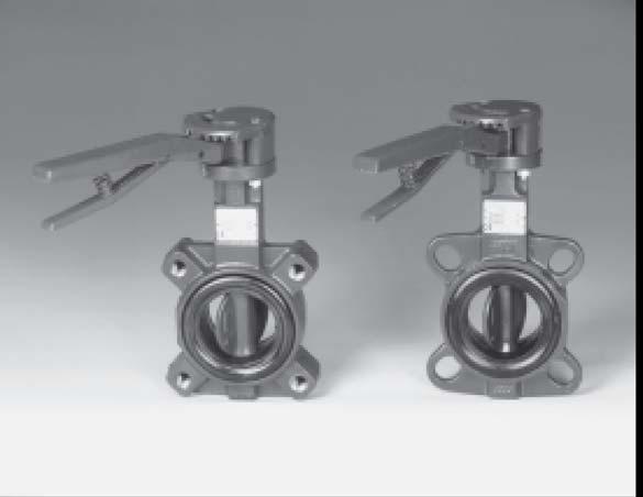

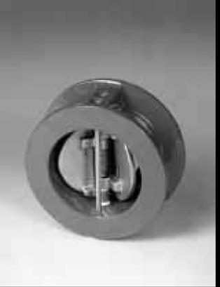
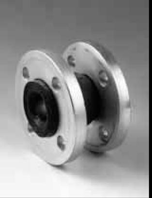
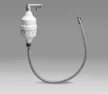
132 ACCESSORIES SORIES AIR SUPPLY UNITS FLOAT SWITCHES VALVES CYLINDER WATER TANK TECHNICAL APPENDIX NON-RETURN VALVES COUPLINGS PRESSURE TRANSMITTER 13
50 Hz. GS20-GS21-GS30 Series. FIXED-SPEED PRESSURE BOOSTER SETS WITH HORIZONTAL CENTRIFUGAL ELECTRIC PUMPS FH and SH SERIES. Cod.
 Hz GS-GS1-GS3 Series FIXED-SPEED PRESSURE BOOSTER SETS WITH HORIZONTAL CENTRIFUGAL ELECTRIC PUMPS FH and SH SERIES Cod. 19191 Rev ev.b.b Ed./1 CONTENTS General introduction... Choice and selection...
GMD20..NL, GMD30..NL* GHV20..NL, GHV30..NL* GHV40..NL, GTKS20..NL* Series
 GMD20..NL, GMD30..NL* GHV20..NL, GHV30..NL* GHV40..NL, GTKS20..NL* Series Fixed and Variable speed Booster sets Maximum operating pressure 16 bar. Flow rates up to 56 m 3 /h 50 Hz * FOR NEDERLAND MARKET
Multiple Pressure Booster Systems With Variable Speed Controller Type BL
 Multiple Pressure Booster Systems With Variable Speed Controller Type BL General Characteristics - Single or multistage pumps - Horizontal or vertical mounting - Total head 30m ~ 250m - Material construction:
Installation, Operation and Maintenance Instructions for Electronically Controlled Pressurisation Units
 Installation, Operation and Maintenance Instructions for Electronically Controlled Pressurisation Units Models: EPS Single Pump EPT Twin Pump EPS-HP EPT-HP Single Pump High Pressure Twin Pump High Pressure
GRUNDFOS DATA BOOKLET. Hydro Solo-E. Complete pressure boosting systems 50/60 Hz
 GRUNDFOS DATA BOOKLET Complete pressure boosting systems 5/6 z Contents Product data Performance range 3 Operating conditions Inlet pressure Type key Product range 5 Construction 5 Installation 5 Mechanical
On-Off switch. Selectable manual control for commissioning. Remote start input for control via an irrigation controller, or external sensor.
 SPEEDMAN VARIABLE SPEED PUMP SET VARIABLE SPEED PUMP SET PRODUCT DESCRIPTION Variable speed / constant pressure system consisting of a Davey VM vertical multistage pump with Speedman controller, VSD unit,
Locator Locator-D-Lux Air-Saver G1 Air-Saver G2
 170663_air_saving_products 17-02-2011 16:42 Pagina 1 Locator Locator-D-Lux Air-Saver G1 Air-Saver G2 AIR SAVING PRODUCTS 170663_air_saving_products 17-02-2011 16:42 Pagina 2 170663_air_saving_products
COMPACT Booster Sets Data Book 50Hz
 Japanese Technology since 1912 COMPACT Booster Sets Data Book 50Hz 50Hz CONTENTS INDEX GP-GPE Page CONTENTS INDEX 2 DEFINITION AND USE OF PRESSURISATION UNITS 101 TYPICAL APPLICATIONS 101 PRINCIPLE OF
Hydro Dome GRUNDFOS INSTRUCTIONS
 GRUNDFOS INSTRUCTIONS Hydro Dome Installation and operating instructions Montage- und Betriebsanleitung Notice d installation et d entretien Istruzioni di installazione e funzionamento Instrucciones de
APPLICATIONS. Pumping of clean, non-muddy liquids in the housing, agricultural and industrial sectors.
 OPERATING RANGES Flow rates of up to: 3 m 3 /h Manometric heads of up to: Max. delivery pressure: Max. intake pressure: Temperature range: 35 9 m CL 1 bar bar - 15 to +11 C* Max. ambient temperature: +
ECONORESS ELECTRONIC EPS & EPT - ENHANCED PRESSURISATION SET INSTALLATION OPERATION & MAINTENANCE DOCUMENTATION
 ECONORESS ELECTRONIC EPS & EPT - ENHANCED PRESSURISATION SET INSTALLATION OPERATION & MAINTENANCE DOCUMENTATION OCT2010 STOKVIS ENERGY SYSTEMS 96R WALTON ROAD EAST MOLESEY SURREY KT8 0DL TEL: 020 87833050
50Hz. water solutions. O SerieS DGO DRO
 Hz water solutions O SerieS DGO DRO D a t a b o o k l e t EN water solutions O SerieS DGO DRO Hz D a t a b o o k l e t O SERIES O Series General characteristics AISI stainless steel lifting and carrying
BUBBLER CONTROL SYSTEM
 BUBBLER CONTROL SYSTEM Description: The HDBCS is a fully automatic bubbler system, which does liquid level measurements in water and wastewater applications. It is a dual air compressor system with, air
BUBBLER CONTROL SYSTEM
 BUBBLER CONTROL SYSTEM Description: The LDBCS is a fully automatic bubbler system, which does liquid level measurements in water and wastewater applications. It is a dual air compressor system with, air
SINGLE VALVE WITH LOW-FLOW BYPASS
 CONTROL VALVES Pressure Reducing Valve Sizing Guide Sizing pilot operated reducing valves is not a complicated process. It starts with determining requirements and following these guidelines in valve size
CALEFFI. Ball zone valves. series /03 GB
 all zone valves series cert. n ISO / Function Zone valves are used to automatically shut-off the flow of carrier fluid distributed to a system. Specifically: -In central heating systems, they support the
Torque Tube TB300 Digital Transmitters
 Page 1 of 7 7E.300-E Issue 4-2009 Description Series TB300 torque tube liquid level instruments utilize the buoyancy exerted on a displacer when immersed in a liquid. The buoyancy on the displacer is proportional
Page - CONSTRUCTIONS 300 SECTIONAL VIEW DRAWING 300 SECTIONAL VIEW TABLE 301 ITEM QUANTITY FOR MODEL 302
 CONTENTS. Page - SPECIFICATIONS 200 SPECIFICATION 200 SELECTION CHART PFC 201 SELECTION CHART 202 TYPE KEY AND CURVE SPECIFICATIONS 203 PERFORMANCE CURVE 2 204 PERFORMANCE CURVE 3 205 PERFORMANCE CURVE
TECHNICAL DATA. Q = C v P S
 Page 1 of 13 1. DESCRIPTION The Viking 6 Model G-6000 Dry Valve Riser Assembly consists of a small profile, light weight, pilot operated valve that is used to separate the water supply from the dry sprinkler
MV-01. Features. 2/2-way Solenoid Valve for Fluids. Description: Application:
 MV-01 2/2-way Solenoid Valve for Fluids Description: Features / Nominal diameters 1/4-2 / Pressure up to 10 bar / 24 V DC and all common AC variants / Forced-lifting The pilot-controlled full-way valve
Aquavar SOLO 2 Frequently Asked Questions
 Aquavar SOLO 2 Frequently Asked Questions How do I size the Aquavar SOLO 2 for the appropriate pump/motor combination? Can I use a 208 Volt motor? Can I run the Aquavar SOLO 2 up to 80HZ? What are the
SIHI LPH-X - Liquid Ring Compressors
 - Liquid Ring Compressors LPH 50523 LPH 60527 Pressure range: Suction volume range: 0.2 to 1.5 bar 260 to 780 m³/h CONSTRUCTION Sterling SIHI liquid ring compressors are displacement compressors with a
Installation, Operation and Maintenance Instructions for Electronically Controlled Pressurisation Units Digital Range
 Installation, Operation and Maintenance Instructions for Electronically Controlled Pressurisation Units Digital Range Models: DS 126 Single Pump / Single System DT 126 Twin Pump / Single System DS 160
KIT. Small Automatic Water Boosters KIT MODELS
 KIT Small Automatic Water Boosters The electronic controller KIT orders the automatic start and stop of the water pump when opening or closing any tap or valve in the installation. There are four main
SonoMeter 30 Energy Meters
 Data Sheet SonoMeter 30 Energy Meters Description The Danfoss SonoMeter 30 is a range of ultrasonic, compact energy meters intended for measuring energy consumption in heating and cooling applications
BOSS PULISCI PROVA IMPIANTI MEDIA
 BOSS PULISCI PROVA IMPIANTI MEDIA Pump for power flushing operations and removal of impurities, suitable for hydraulic, solar, floor systems and for cooling circuits of medium size. Suitable for buildings,
Mobile High Pressure Compressor Unit for Compressing Air and Breathing Air. PE 250-TE with compressor control (optional equipment)
") Mobile High Pressure Compressor Unit for Compressing Air and Breathing Air Types: PE 200-TE PE 250-TE PE 300-TE Production status: F02 PE 250-TE with compressor control (optional equipment) General Medium
Mobile High Pressure Compressor Unit for Compressing Air and Breathing Air Types: PE 200-TE PE 250-TE PE 300-TE Production status: F02 PE 250-TE with compressor control (optional equipment) General Medium
TECHNICAL DATA 3 MODEL G-3000 DRY VALVE RISER ASSEMBLY
 Page 1 of 13 1. DESCRIPTION The Viking 3 Model G-3000 Dry Valve Riser Assembly is equipped with a small profile, light weight, pilot operated valve that is used to separate the water supply from the dry
TECHNICAL DATA. Q= Cv S
 Page 1 of 13 1. DESCRIPTION The Viking 4 inch Model G-4000 Dry Valve Riser Assembly consists of a small profile, light weight, pilot operated valve that is used to separate the water supply from the dry
Liquid ring vacuum pumps in compact design
 Liquid ring vacuum pumps in compact design LEM 25, LEM 5 Pressure range: Suction volume flow: 33 to 113 mbar 4 to 6 m³/h CONSTRUCTION SIHI liquid ring vacuum pumps are displacement pumps of uncomplicated
High Pressure Breathing Air Compressors
 High Pressure Breathing Air Compressors [ Full variety for different applications] MSA offers a comprehensive range of high pressure breathing air compressors for both the firefighting and diving market,
TECHNICAL DATA. Q = C v P S
 Preaction 346a 1. Description The 6 Model G-6000P Electric Release Preaction System Riser Assembly can be used as a Single Interlock Preaction System with Electric Release, or as a Double Interlock Preaction
Seated valves VRB 3, VRG 3
 Data sheet Seated valves VRB 3, VRG 3 Description VRB, VRG valves provide a quality, cost effective solution for most water and chilled applications. These valves may be used with glycol concentrations
AIR SAVING PRODUCTS ADDING VALUE AIR-SAVER LOCATOR LOCATOR-EV
 AIR SAVING PRODUCTS AIR-SAVER LOCATOR LOCATOR-EV ADDING VALUE REL LIABLE COMPRESSED AIR CONDENSATE MANAGEMENT AND ENERGY SAVING PRODUCTS Air saving products INDEX Chapter Content 1 Introduction to compressed
Pressure transmitters EMP 2
 Data sheet Pressure transmitters EMP 2 The high accuracy pressure transmitter EMP 2 is designed for monitoring and control in marine and industial applications and offers a reliable pressure measurement,
Submersible Electric Pumps for drainage of clean and slightly dirty water DIWA Series
 Submersible Electric Pumps for drainage of clean and slightly dirty water DIWA Series Submersible pumps for clean and slightly dirty water manufactured in AISI 304 stainless steel. Head up to 20 metres,
![[Instruments for vacuum measurement, checking and adjustment] 3](/thumbs/94/121874202.jpg "[Instruments for vacuum measurement, checking and adjustment] 3")
Level switches Series LD Vibrating fork level switch for liquids and solids
 Level switches Series LD Vibrating fork level switch for liquids and solids Robust and compact Suitable for liquids (model LD61) and solids (model LD60) No moving parts, low maintenance Corrosion resistant
TECHNICAL DATA. Q = C v P S
 January 6, 2012 Preaction 348a 1. Description Viking supervised Surefire Preaction Systems utilize the Viking G-6000P Valve. The small profile, lightweight, pilot operated Viking G-6000P Valve comes complete
DMK 458. Pressure Transmitter for Marine and Offshore. Ceramic Sensor. accuracy according to IEC 60770: standard: 0.25 % FSO option: 0.
 Pressure Transmitter for Marine and Offshore Ceramic Sensor accuracy according to IEC 60770: standard: 0.5 % FSO option: 0. % FSO Nominal pressure from 0... 40 mbar up to 0... 0 bar Output signals -wire:
TECHNICAL DATA. Q = C v P S
 January 6, 2012 Preaction 333a 1. Description Viking supervised Surefire Preaction Systems Utilize the Viking G-3000P Valve. The small profile, lightweight, pilot-operated Viking G-3000P Valve comes complete
COMPRESSED AIR SAVING PRODUCTS INDEX. Useful information AIR-SAVER G1 AIR-SAVER G2 LOCATOR. Condensate Management Specialist
 INDEX Useful information AIR-SAVER G1 AIR-SAVER G2 LOCATOR COMPRESSED AIR SAVING PRODUCTS Condensate Management Specialist Information provided herewith is believed to be accurate and reliable. However,
TECHNICAL DATA. Q = C v P S
 January 6, 2012 Preaction 331a 1. Description Viking supervised Double-Interlocked Electric/Pneumatic Release Preaction Systems utilize the Viking G-3000P Valve. The small profile, lightweight, pilot-operated
Flamco Airfix D-E. Installation and operating instructions. 1999, Flamco eps
 Airfix D-E 6442.eps GB Installation and operating instructions 1999, Exclusion of liability All operation and maintenance related technical information, data and instructions contained in these installation
Level switches Series LD Vibrating fork level switch for liquids and solids
 Level switches Series LD Vibrating fork level switch for liquids and solids Robust and compact Suitable for liquids (model LD61) and solids (model LD60) No moving parts, low maintenance Corrosion resistant
Monitoring device NTS 30
 P R O D U C T I N F O R M A T I O N Electronic level- and temperature monitoring device Monitoring device NTS 30 Contents Description Description... 2 Operating... 3 Design and electrical data... 4 Circuit
4/2 way Pneumatic Solenoid Valve
 4/2 way Pneumatic Solenoid Valve Compact design Push-over solenoid coil Exhaust air can be regulated Tube, threaded and sub-base connections Type combined with Seat valve version Type 2508 Type 2510/11
Seated valves (PN 6) VL 2 2-way valve, flange VL 3 3-way valve, flange
 VL 2 2-way valve, flange VL 3 3-way valve, flange") Data sheet Seated valves (PN 6) VL 2 2-way valve, flange VL 3 3-way valve, flange Description VL 2 VL 3 VL 2 and VL 3 valves provide a quality, cost effective solution for most water and chilled applications.
Data sheet Seated valves (PN 6) VL 2 2-way valve, flange VL 3 3-way valve, flange Description VL 2 VL 3 VL 2 and VL 3 valves provide a quality, cost effective solution for most water and chilled applications.
Liquid ring vacuum pumps in compact design
 Liquid ring vacuum pumps in compact design, Pressure range: Suction volume flow: 33 to 113 mbar 3 to 58 m³/h CONSTRUCTION TYPE SIHI liquid ring vacuum pumps are displacement pumps of uncomplicated and
TECHNICAL DATA. Q = C v P S
 January 6, 2012 Preaction 347a 1. Description Viking supervised Double-Interlocked Electric/Pneumatic Release Preaction Systems utilize the Viking G-6000P Valve. The small profile, lightweight, pilot operated
Pressure Automated Calibration Equipment
 GE Measurement & control Pressure Automated Calibration Equipment Safety Instructions and User Guide - K0447 PACE5000 PACE6000 K0447 Issue No. 9 1 10 1 PACE5000 1 2 3 4 5 PACE6000 2 6 7 8 3 4 5 6 7 8 9
Uniflair LE TDAR-TUAR
 Uniflair LE TDAR-TUAR Direct Expansion air-cooled units with backward-curved fans 20-100kW > Perimeter cooling for medium/large data center > Refrigerant R-410A Available Versions: > Downflow (TDAR) >
AIR-SAVER G1 AIR-SAVER G2 LOCATOR-EV COMPRESSED AIR CONDENSATE MANAGEMENT AND ENERGY SAVING PRODUCTS AIR SAVING PRODUCTS
 AIR-SAVER G1 AIR-SAVER G2 LOCATOR-EV ENVIRONMENT ADDING VALUE SAFEGUARD RELIABLE COMPRESSED AIR CONDENSATE MANAGEMENT AND ENERGY SAVING PRODUCTS AIR SAVING PRODUCTS Air saving products INDEX Chapter Content
Seated valves (PN 16) VF 2 2-way valve, flange VF 3 3-way valve, flange
 VF 2 2-way valve, flange VF 3 3-way valve, flange") Data sheet Seated valves (PN 16) VF 2 2-way valve, flange VF 3 3-way valve, flange Description VF 2 VF 3 VF 2 and VF 3 valves provide a quality, cost effective solution for most water and chilled applications.
Data sheet Seated valves (PN 16) VF 2 2-way valve, flange VF 3 3-way valve, flange Description VF 2 VF 3 VF 2 and VF 3 valves provide a quality, cost effective solution for most water and chilled applications.
(AS AT 31 st MARCH, 2002)
") ACACA PROTOCOL 2000 (AS AT 31 st MARCH, 2002) ACACA PROTOCOL 2000 INCLUDES (A) CODE OF PRACTICE FOR MANUFACTURERS AND/OR SUPPLIERS OF COMMERCIAL AIR COMPRESSORS AND METHOD FOR DETERMINING (B) RECIPROCATING
ACACA PROTOCOL 2000 (AS AT 31 st MARCH, 2002) ACACA PROTOCOL 2000 INCLUDES (A) CODE OF PRACTICE FOR MANUFACTURERS AND/OR SUPPLIERS OF COMMERCIAL AIR COMPRESSORS AND METHOD FOR DETERMINING (B) RECIPROCATING
KSB Delta Compact Type Series Booklet
 Pressure Booster System KSB Delta Compact Type Series Booklet Legal information/copyright Type Series Booklet KSB Delta Compact All rights reserved. The contents provided herein must neither be distributed,
Installation, Operation and Maintenance Instructions for Electronically Controlled Pressurisation Units
 Installation, Operation and Maintenance Instructions for Electronically Controlled Pressurisation Units Micro-S / Micro-S Digital Wall Hung Unit Please fulfil all listed requirements prior to and during
Pressure independent control valve (PICV) FLOWMATIC
 FLOWMATIC") Pressure independent control valve (PICV) FLOWMATIC 145 series FM 21654 003 01262/19 GB replaces dp 01262/17 GB Function The pressure independent control valve is a device composed of an automatic flow
Pressure independent control valve (PICV) FLOWMATIC 145 series FM 21654 003 01262/19 GB replaces dp 01262/17 GB Function The pressure independent control valve is a device composed of an automatic flow
TECHNICAL DATA Q = C. v P S. 2 Model G-2000 Dry valve. Page 1 of 13
 Page 1 of 13 1. Description The Viking 2 Model G-2000 Dry Valve Riser Assembly consists of a small profile, light weight, pilot operated valve that is used to separate the water supply from the dry sprinkler
AIR-SAVER G1 AIR-SAVER G2 LOCATOR LOCATOR-EV COMPRESSED AIR CONDENSATE MANAGEMENT AND ENERGY SAVING PRODUCTS AIR SAVING PRODUCTS
 AIR-SAVER G1 AIR-SAVER G2 LOCATOR LOCATOR-EV ENVIRONMENT ADDING VALUE SAFEGUARD RELIABLE COMPRESSED AIR CONDENSATE MANAGEMENT AND ENERGY SAVING PRODUCTS AIR SAVING PRODUCTS AIR SAVING PRODUCTS INDEX Chapter
C-Flow Coriolis Mass Flow Meters
 Coriolis Mass Flow Meters Ready for Take Off The New Compact C-Flow Küppers Elektromechanik GmbH The C-Flow The C-Flow Coriolis Mass Meters consist of two components: KCE Transmitter KCM Transducer 2 KEM
1. PARTS INTRODUCTION ELECTRICAL NOTES INSTALLATION 5/6. 5. START UP 6/7. 6. MAINTENANCE 7/8/9. 7. PRESSURE SWITCH ADJUSTMENTS 9/10.
 CONTENTS 1. PARTS 3. 2. INTRODUCTION 4. 3. ELECTRICAL NOTES 5. 4. INSTALLATION 5/6. 5. START UP 6/7. 6. MAINTENANCE 7/8/9. 7. PRESSURE SWITCH ADJUSTMENTS 9/10. 8. ELECTRICAL CONNECTIONS 10/11. 9. SPECIFICATIONS
Product Range. High performance and economic high pressure solutions Made in Germany
 Product Range Purification Storage Filling Panels Nitrox/Trimix High performance and economic high pressure solutions Made in Germany www.lw-compressors.com 2 Lenhardt & Wagner Solid Growth Lenhardt &
Instruction Manual Differential Pressure Transmitter
 DE13 Instruction Manual Differential Pressure Transmitter Table of Contents 1. Safety Instructions 2. Intended Applications 3. Product Description and Functions 4. Installation 5. Commissioning 6. Maintenance
Installation, Operating, Maintenance and Safety Instructions for. Pressurised water systems for boats
 FLOMAX-SYSTEM DOC532/11 Installation, Operating, Maintenance and Safety Instructions for FLOMAX-SYSTEM Pressurised water systems for boats CW343A FloMax System 12 volt d.c. CW344A FloMax System 24 volt
Submersible Pumps Product Overview
 TM/TMW 32 Duty chart (2 -pole, 50 Hz) H[m] 10 8 6 TM/TMW 32 Submersible Pumps Product Overview Submersible Pumps Basement drainage pump Applications: Pumping clear or slightly soiled water from tanks,
INDUSTRIAS IBAIONDO, HYDROPNEUMATIC TANKS
 IBAIONDO, HYDROPNEUMATIC TANKS IBAIONDO, INTRODUCTION Hydropneumatic tanks are designed to be used in potable water supply installations as a part of the pressure booster set in order to ensure the adequate
Columbus Instruments
 0215-003M Portable O 2 /CO 2 /CH 4 Meter User s Manual Columbus Instruments 950 NORTH HAGUE AVENUE TEL:(614) 276-0861 COLUMBUS, OHIO 43204, USA FAX:(614) 276-0529 1 www.colinst.com TOLL FREE 1-800-669-5011
DEEP WELL SUBMERSIBLE PUMPS. An ISO 9001 & Company
 C.R.I. PUMPS DEEP WELL SUBMERSIBLE PUMPS EVERGREEN SERIES - 5Hz An ISO 91 & 141 Company Submersible Pumps C.R.I. Submersible Pumps are the products of the expertise gained from over four decades of experience,
DIAPHRAGM PUMPS WITH KNF STABILIZATION SYSTEM
 DIAPHRAGM PUMPS WITH KNF STABILIZATION SYSTEM DATA SHEET E 037 N 940.5 APE as AC version in IP 54 N 940.5 APE-W with multi-voltage power supply input (As an option adjustable with potentiometer or by external
erc-o 2 -tech Ò innovative gas systems Markwerbener Str Weißenfels Germany
 Compart Umwelttechnik GmbH erc-o 2 -tech Ò innovative gas systems Markwerbener Str. 24 06667 Weißenfels Germany Phone: 0049 (0) 3443/2901-0 Fax: 0049 (0) 3443/2901-12 Mail: compart-weissenfels@t-online.de
Flamco Flexcon M-P Pump automat
 Flexcon M-P Pump automat 0664 Flex MP-eps GB Installation and operating instructions 1999, Flamco 2 Installation and operating instructions Flexcon M-P pump automat Dear customer, GB With the purchase
FLOW. State of the Art ELECTRONIC PUMPS CONTROLLERS. * Electronic starters. * Inverters. * Protection devices YOURWATER UNDER CONTROL
 PRODUCT CATALOGUE State of the Art * Electronic starters * Inverters * Protection devices For * Stable Pressure Control * Dry Run Protection * Energy Saving * Water Saving YOURWATER UNDER CONTROL DPI Trading
The CWE / HWE-R Series: Overview. Frame and cabinet covering
 Table Of Contents The CWE / HWE-R Series: Overview...... 1 Frame and cabinet covering... 1 Refrigerant gas...... 2 Compressors...... 2 Condensers...... 2 Fans... 3 Evaporator...... 3 Refrigerant circuit......
Euroswim Swimming pool pumps. 11/2010 Copyright of DWT GROUP 1
 Euroswim Swimming pool pumps 1 SWIMMING POOL PUMPS What EUROSWIM is an horizontal self-priming centrifugal electropump suitable for: Domestic swimming pools Residential swimming pools Agricoltural, industrial
System Pressure Manager Standard & System Pressure Manager Plus
 System Pressure Manager Standard & System Pressure Manager Plus Installation, Commissioning & Servicing Instructions Note: THESE INSTRUCTIONS MUST BE READ AND UNDERSTOOD BEFORE INSTALLING, COMMISSIONING,
Budget Range Operators Handbook
 Budget Range Operators Handbook BAMBI AIR COMPRESSORS LTD 152 Thimble Mill Lane Heartlands Birmingham B7 5HT United Kingdom Tel: 0121 322 2299 Fax: 0121 322 2297 Email: sales@bambi-air.co.uk www.bambi-air.co.uk
CCT-7320/ROC-2313 Reverse Osmosis Controller
 CCT-7320/ROC-2313 Reverse Osmosis Controller 1 General The instrument is a combined control instrument of a reverse osmosis controller and an on-line conductivity instrument. It can perform the operation
STAINLESS STEEL GRAND SERIES
 STAINLE STEEL GRAND SERIES STAINLE STEEL GRAND SERIES DEEPWELL SUBMERSIBLE PUMPS STAINLE STEEL - GRAND SERIES C.R.I. Always equips itself in advance to face the exponentially growing technological challenges
Pressure Transmitters 36 F-27839
 Pressure Transmitters 36 F-27839 SPD310/SPD360 Air Differential schneider-electric.com 37 SPD310/SPD360 SPD310/SPD360 differential pressure transmitters are intended for use in air handling systems for
Liquid ring compressor
 Liquid ring compressor KLH 47005, KLH 47105 Compression pressures: Suction volume flow: 2 to 11 bar 56 to 65 m³/h CONSTRUCTION TYPE Sterling SIHI liquid ring compressors are displacement compressors of
PRODUCTS CATALOGUE 2017 / Torino - Strada Settimo 388/15 Tel (+39) /43 Fax (+39)
 /43 Fax (+39)") PRODUCTS CATALOGUE 2017 / 2018 10156 Torino - Strada Settimo 388/15 Tel (+39) 011.223.68.42 /43 Fax (+39) 011.223.67.67 info@ebarbero.com www.ebarbero.com CATALOGO INDEX PRODOTTI 2017 / 2018 Pumps for
PRODUCTS CATALOGUE 2017 / 2018 10156 Torino - Strada Settimo 388/15 Tel (+39) 011.223.68.42 /43 Fax (+39) 011.223.67.67 info@ebarbero.com www.ebarbero.com CATALOGO INDEX PRODOTTI 2017 / 2018 Pumps for
GM Series Dual-Block Multi-Function Gas Control Valves
 Installation Sheets Manual 121 Gas Combustion Combination Controls and Systems Section G Technical Bulletin GM Issue Date 0297 GM Series Dual-Block Multi-Function Gas Control Valves Figure 1: GM Series
TECHNICAL DATA MAINTENANCE AIR COMPRESSOR MODEL G-1
 Dry 131h 1. DESCRIPTION The Viking Model G-1 Maintenance Air Compressor is an electric motor-driven, aircooled, single-stage, oil-less compressor. The unit is equipped with a check valve and provides a
Glycol Systems. Engineering Manual. 1/2 to 10 Hp Pumps 3 to 190 Tons Drycoolers (60 Hz Data) Pump Packages & Remote Outdoor Drycoolers
 Pump Packages & Remote Outdoor Drycoolers") Glycol Systems Engineering Manual 1/2 to 10 Hp Pumps 3 to 190 Tons Drycoolers (60 Hz Data) Pump Packages & Remote Outdoor Drycoolers Stulz Air Technology Systems, Inc. Table of Contents Section - 1 Table
Glycol Systems Engineering Manual 1/2 to 10 Hp Pumps 3 to 190 Tons Drycoolers (60 Hz Data) Pump Packages & Remote Outdoor Drycoolers Stulz Air Technology Systems, Inc. Table of Contents Section - 1 Table
Pilot valves for pilot operated servo valves
 Data sheet Pilot valves for pilot operated servo valves The range of pilot valves consists of: Constant-pressure pilot valve, type CVP (LP) and CVP (HP) Differential-pressure pilot valve, type CVPP (LP)
Installation, operating and maintenance Instructions for Seemag bypass level indicator
 Issue: S Date: 05-09-14 Type G35 General information The Seetru bypass magnetic level indicator, abbreviate SEEMAG, serves to show the filling level of fluids in tanks, basins, tubes etc. The Seemag operates
Automatic balancing valves ASV
 Automatic balancing valves ASV ASV-P ASV-PV ASV-PV ASV-PV ASV-I ASV-M 15-40 15-40 50 65-100 15-50 15-50 Description / Application ASV balancing valves are used for dynamic hydronic balance in heating and
GENERIC MANUAL - FOR REFERENCE ONLY. ALL BESPOKE UNITS WILL HAVE PROJECT SPECIFIC DETAILS
 GENERIC MANUAL - FOR REFERENCE ONLY. ALL BESPOKE UNITS WILL HAVE PROJECT SPECIFIC DETAILS EnwaMatic Bespoke BS 300 Contents Declaration of conformity: 2 Pressure test certificate: 3 Contacts: 4 Installation
6-way characterised control valves DN15 and DN 20
 6-way characterised control valves DN15 and DN 20 Table of contents Introduction 2 Project planning 2 Structure of the 6-way characterised control valves 2 Range of use 2 Characteristic curve 3 Flow direction
The Discussion of this exercise covers the following points: Pumps Basic operation of a liquid pump Types of liquid pumps The centrifugal pump.
 Exercise 2-3 Centrifugal Pumps EXERCISE OBJECTIVE In this exercise, you will become familiar with the operation of a centrifugal pump and read its performance chart. You will also observe the effect that
Autocalibration Systems For In Situ Oxygen Analyzers
 Product Data Sheet PDS 106-340AC SPS 4000, IMPS 4000, and MPS 3000 January, 1999 Autocalibration Systems For In Situ Oxygen Analyzers Cost-effective autocalibration systems for installations ranging from
Expansion Vessels for Potable Installations
 4. Expansion Vessels for Potable Installations Domestic installations lose millions of litres of potable water due to expansion water leaking from the vent and expansion pipe. Flamco s Airfix diaphragm
Solenoid valves VZWF, force pilot operated
 Key features and overview Function Normally closed solenoid valve with diaphragm and forced lifting. When the solenoid is energised, the differential pressure from the secondary side of the diaphragm is
High-performance submersible pressure transmitter For level measurement Model LH-10
 Electronic pressure measurement High-performance submersible pressure transmitter For level measurement Model LH-10 WIKA data sheet PE 81.09 Applications Level measurement in rivers and lakes Deep well
OPTIBAR P 1010 C Technical Datasheet
 Technical Datasheet Pressure transmitter with recessed diaphragm for general applications Wide variety thanks to modular design Measuring ranges up to 250 bar / 3750 psi High overload and temperature stability
Measuring range Δp (span = 100%) Pa
 Pa") 4.4/ RLE 5: Volume-flow controller, continuous How energy efficiency is improved Enables demand-led volume flow control for the optimisation of energy consumption in ventilation systems. Areas of application
4.4/ RLE 5: Volume-flow controller, continuous How energy efficiency is improved Enables demand-led volume flow control for the optimisation of energy consumption in ventilation systems. Areas of application
TotalPac X Single interlock Preaction system Electric release
 DESCRIPTION This TOTALPAC X integrated fire protection system by FireFlex Systems Inc. consists of a preaction system trim totally preassembled, pre-wired and factory tested. All electrical and mechanical
LMP 307. Stainless Steel Probe. Stainless Steel Sensor. accuracy according to IEC 60770: standard: 0.35 % FSO option: 0.25 % / 0.
 LMP 07 Stainless Steel Sensor accuracy according to IEC 60770: standard: 0.5 % FSO option: 0.5 % / 0. % FSO Nominal pressure from 0... mho up to 0... 50 mho Output signals -wire: 4... 0 ma -wire: 0...
SCA Series Inverted Bucket Steam Traps
 0770050/5 IM-P077-06 ST Issue 5 SCA Series Inverted Bucket Steam Traps Installation and Maintenance Instructions 1. General safety information 2. General product information 3. Installation 4. Commissioning