Compressed Air Cleaning Filter Series
|
|
|
- Bruce Weaver
- 6 years ago
- Views:
Transcription

1 Compressed ir Cleaning Filter Series M /FF Series For Water Droplet, Solid/Oil Separation and Deodorization Modular connection, Space-saving design, Labor-saving in piping! Uses the same spacer as the F.R.L. combination C series. Possible to make a modular connection with products such as R series regulator. Options added ddition: 5 types 1. MPa specifications FKM specifications With differential pressure switch (125 VC, 30 VDC) With differential pressure switch (30 VDC) White vaseline specifications Spacer Note) Note) Spacer with bracket cannot be mounted. Use the attached bracket. MG C, FF C, M C, MD C MH C, ME C, MF C Differential pressure switch MH + ME MH + ME + MF Height and weight reduced by up to 40% New MG C, FF C, M C, MD C MH C, ME C, MF C Modular connection example The C type is only suitable for modular connection. Compact, Lightweight (ME C, MF C) Current Water Droplet Separation Water Separator/MG Solid/Oil Separation Main Line Filter/FF Mist Separator/M Micro Mist Separator/MD Micro Mist Separator with Pre-filter/MH Super Mist Separator/ME Deodorization Odor Removal Filter/MF H HW T B G K MG FF M MD MH ME MF D D 3 B

2 M /FF Series Water droplet separation Water Separator Water droplet removal ratio: % Large dust particle filtration, Oil droplet separation Main Line Filter Nominal filtration rating: 3 µm [Filtration efficiency: %] FF2C to 22C Dust filtration, Oil mist separation Mist Separator MG150C to 550C FF37B/75B Nominal filtration rating: 0.3 µm [Filtration efficiency:.%] Oil mist density at outlet: Max. 1.0 mg/m 3 (NR) [ 0.8 ppm] M150C to 550C Dust filtration, Oil mist separation Micro Mist Separator Nominal filtration rating: 0.01 µm [Filtration efficiency:.%] Oil mist density at outlet: Max. 0.1 mg/m 3 (NR) [ 0.08 ppm] MG50/850 FF75 to 2 M50/850 Model 150C 250C 350C MG 450C 550C C 4C 8C 11C 22C FF 37B 75B C 250C 350C M 450C 550C C 250C 350C 450C MD 550C Rated flow L/min (NR) ,500 2,0 3,700,000 12, ,500 2,0 3,700,000 12,000 12,400 23,700 30,000 45, ,500 2,0 3,700,000 12, ,000 2,000 3,700,000 12,000 24,000 40,000 Port size 1/8, 1/4 1/4, 3/8 3/8, 1/2 1/2, 3/4 3/4, 1 1, 1 1/2 1 1/2, 2 1/8, 1/4 1/4, 3/8 3/8, 1/2 1/2, 3/4 3/4, 1 1, 1 1/2 1 1/2, 2 50(2B) flange 80(3B) flange 0(4B) flange 1/8, 1/4 1/4, 3/8 3/8, 1/2 1/2, 3/4 3/4, 1 1, 1 1/2 1 1/2, 2 1/8, 1/4 1/4, 3/8 3/8, 1/2 1/2, 3/4 3/4, 1 1, 1 1/2 1 1/2, 2 50(2B), 80(3B), 0(4B) flange 0(4B), 150(B) flange Note Piping support type Piping support type Free standing type Piping support type Piping support type Free standing type MD150C to 550C MD50, 850 B 4
3 Compressed ir Cleaning Filter Series M /FF Series Dust filtration, Oil mist separation Micro Mist Separator with Pre-filter Built-in 0.3 µm pre-filter The M + MD element have been integrated to achieve a space-saving design. Nominal filtration rating: 0.01 µm [Filtration efficiency:.%] Oil mist density at outlet: Max. 0.1 mg/m 3 (NR) [ 0.08 ppm] Model 150C 250C 350C MH 450C 550C 50 Rated flow L/min (NR) ,000 2,000 3,700,000 Port size 1/8, 1/4 1/4, 3/8 3/8, 1/2 1/2, 3/4 3/4, 1 1, 1 1/2 Note Piping support type H HW T , /2, 2 B 150C 0 1/8, 1/4 Super Mist Separator Odor Removal Filter MH150C to 550C MH50/850 Dust filtration, Oil mist adsorption Color change indicates when element is saturated. Nominal filtration rating: 0.01 µm [Filtration efficiency:.%] Oil mist density at outlet: Max mg/m 3 (NR) [ ppm] Cleanliness at outlet: Not more than 0 particles of size 0.3 µm or larger/ft 3 [35 particles or less/ L (NR)] ME150C to 550C ME50/850 Deodorization Nominal filtration rating: 0.01 µm [Filtration efficiency:.%] Oil mist density at outlet: Max mg/m 3 (NR) [ ppm] ME MF 250C 350C 450C 550C C 250C 350C 450C 550C ,000 2,000 3,700,000 12, ,000 2,000 3,700,000 12,000 1/4, 3/8 3/8, 1/2 1/2, 3/4 3/4, 1 1, 1 1/2 1 1/2, 2 1/8, 1/4 1/4, 3/8 3/8, 1/2 1/2, 3/4 3/4, 1 1, 1 1/2 1 1/2, 2 Piping support type Piping support type G K MG FF M MD MH ME MF D D MF150C to 550C MF50, B
4 Compressed ir Cleaning Filter Series M /FF Series Series Water removal rate Nominal filtration rating Oil mist density at outlet Smell Page Water Droplet Separation Water Separator Eliminates water droplets in the compressed air. MG Series % P.7 Main Line Filter Eliminates impurities such as oil and foreign matter, etc. in compressed air. FF Series 3 µm (Filtration efficiency: %) P.215 Deodorization Solid/Oil Separation Mist Separator Eliminates oil mist in compressed air or rust sized 0.3 µm or more, and foreign matter such as carbon. Micro Mist Separator Eliminates foreign matter sized 0.01 µm or more, or oil particles in an aerosol state. Micro Mist Separator with Pre-filter Incorporates pre-filter (equivalent to the M series) into micro mist separator. Super Mist Separator Captures foreign matter sized 0.01 µm or more and adsorbs oil particles in an aerosol state. Odor Removal Filter Eliminates odor from compressed air. M Series MD Series MH Series ME Series MF Series 0.3 µm (Filtration efficiency:.%) 0.01 µm (Filtration efficiency:.%) 0.01 µm (Filtration efficiency:.%) 0.01 µm (Filtration efficiency:.%) 1 mg/m 3 (NR) ( 0.8 ppm) (after oil saturation) 0.1 mg/m 3 (NR) ( 0.08 ppm) (after oil saturation) 0.01 mg/m 3 (NR) ( ppm) mg/m 3 (NR) ( ppm) Reduces oil smell. Deodorizes oil smell. P.223 P.231 P.241 P.24 P.257 Operating State and Proper Use of uto P.25 Optional ccessories (Spacer for Modular Connection, Piping dapter) P.2 Bowl ssembly P.28 Options Rubber material: FKM - reversal direction White vaseline For medium air pressure guide 1/4 female threaded With element service indicator With differential pressure switch (with indicator) (125 VC, 30 VDC) Refer to How to Order of respective models. pplicable only to the FF37B, 75B, M 50 and 850 by Made to Order. With differential pressure gauge (X) Manage the replacement period by monitoring the clogged element. With differential pressure switch (with indicator) (X37) The differential pressure used as the guide for the element replacement period, can be checked Made to Order visually and with an electrical signal. With - flange (X15) Flange piping connection With differential pressure gauge, - flange (X17) The replacement period due to clogging of the element can be checked by the differential pressure gauge. Flange piping connection pplicable only to the FF37B, 75B, M 50 and 850. Specific Product Precautions uto drain, drain piping threaded connection type (X2) Threaded connection for the piping of the auto drain exhaust port White vaseline specifications (X12) Using white vaseline for lubricant. Main line filter for high flow rate with nominal filtration rating of 0.3 µm (X13) This filter is for high flows with a nominal filtration rating the same as the M series mist separator. With by-pass port (X30) Ports connected to the and sides are provided in two locations. This specification can be used for applications which do not require flow rates, which leads to reduction in piping labor and saves space. P.272 P.277 uto Valve, Motor Operated uto, Heavy Duty uto, Differential Pressure Gauge P.37
5 Water Separator MG Series RoHS Can remove water droplets in compressed air. Use this product in cases where water must be avoided, but not so dry as when an air dryer is used. Through the adoption of a dedicated element and the ample housing interior space, a % water removal rate has been achieved. Caution Water separator can remove water droplets, but it cannot remove moisture. Condition of inlet air Pressure: 0.7 MPa Temperature: 25 C Relative humidity: 0% Liquid water content (Water droplet content): 15 g/m 3 (NR) Compressed air flow: Rated flow of each model Water removal rate (%) = Removed water (Water droplet) (g) x 0 Inflowed water (Water droplet) (g) Modular connection is possible with MG150C to 550C. (For details, refer to page 2.) Model Model MG150C MG250C MG350C MG450C MG550C MG50 MG850 Note) Rated flow (L/min (NR)) Port size 1 8, , , , , 1 1, , 2 Weight (kg) Note) capacity at 0.7 MPa. capacity varies depending on the operating pressure. Refer to Flow Rate Characteristics (page 2) and Maximum Flow Capacity Line (page 211). Specifications Fluid Compressed air Max. operating pressure 1.0 MPa Min. operating pressure 0.05 MPa Proof pressure 1.5 MPa mbient and fluid temperature 5 to 0 C Water removal rate % Element replacement period 2 years or when pressure drop reached 0.1 MPa With auto drain: 0.1 MPa (N.O. type) or 0.15 MPa (N.C. type) ccessory Part No. pplicable model MG150C MG250C MG350C MG450C MG550C MG50 MG850 Bracket assembly M-BM1 M-BM2 M-BM3 M-BM4 M-BM5 BM5 BM57 (with 2 mounting screws) Caution Be sure to read this before handling the products. Refer to back page 50 for Safety Instructions and pages to 8 for ir Preparation Equipment Precautions. H HW T B G K MG FF M MD MH ME MF D D MG150C to 550C MG50/850 ( cock specifications) (uto drain specifications) Made to Order (For details, refer to page 272.) 7
6 MG Series How to Order MG150C to 550C MG 550 C Port Options Size size 150 1/8 1/4 3/8 1/2 3/4 1 Thread type Type Nil Rc F G N NPT Port size pplicable size ccessory Description Nil B Bracket 1 1 Bracket is included, (but not assembled). Nil F H J R V Made to Order s are only added at the end for Made to Order. Refer to page 272 and later for the contents of Made to Order, How to Order, and the applicable models. Option 3 Multiple options can be selected. Refer to the table below for the available combinations. Indicate symbols in alphabetical order. Description Rubber material: FKM For medium air pressure (1. MPa) guide 1/4 female threaded 5 - reversal direction White vaseline 5 Without a valve function uto drain 2 3 Description Nil Without auto drain (With drain cock 4 ) C N.C. (Normally closed) port is closed when pressure is not applied. D N.O. (Normally open) port is open when pressure is not applied. 2 Refer to page 25 for proper use of the auto drain. (Only one auto drain specification can be selected.) 3 Refer to the following table for the available combinations of the auto drain specifications and options. 4 When the option J is selected, the auto drain and drain cock are not available. uto Specifications/Option Combinations : ll types of auto drain specifications are available. (including drain guide, J specification) : N.C. auto drain ( C specification) is not available. : Both N.C. and N.O. auto drain ( C, D specification) are not available. F H R V Nil F H R V : Not available F: Rubber material: FKM FKM is used for the parts such as O-ring and gasket. H: For medium air pressure (1. MPa) Can be used up to 1. MPa at maximum. J: guide 1/4 female threaded Pipe threaded connection for the drain exhaust port 1/4 female threaded R: - reversal direction Flow direction: Right to left (Flow direction of the standard: Left to right) V: White vaseline The body/housing is degreased, and the grease used for the parts requiring lubrication has been changed to white vaseline. B 8
7 Water Separator MG Series MG50/850 MG 50 How to Order Options Size Thread type Type Nil Rc F G N NPT Port size Port size pplicable size ccessory Description Nil B Bracket 1 1 Bracket is included, (but not assembled). J: guide 1/4 female threaded Pipe threaded connection for the drain exhaust port 1/4 female threaded Made to Order s are only added at the end for Made to Order. Refer to page 272 and later for the contents of Made to Order, How to Order, and the applicable models. Option 2 Multiple options can be selected. Refer to the table below for the available combinations. Indicate symbols in alphabetical order. Description Nil J guide 1 4 female threaded 5 R - reversal direction 5 Without a valve function uto drain 2 Description Nil Without auto drain (With drain cock 3 4 ) D N.O. (Normally open) port is open when pressure is not applied. 2 Refer to the following table for the available combinations of the auto drain specifications and options. 3 When the option J is selected, the auto drain and drain cock are not available. 4 Body size 850 is equipped with a ball valve (Rc 3/8). Mount a piping adapter -P0 (page 27) to the ball valve if NPT 3/8 female threaded is required. uto Specifications/Option Combinations : vailable : Not available uto drain specifications/option uto drain specifications Option pplicable model D J R MG50 MG850 uto drain specifications N.O. auto drain guide 1 4 D J Option - reversal direction R R: - reversal direction Flow direction: Right to left (Flow direction of the standard: Left to right) H HW T B G K MG FF M MD MH ME MF D D
 / Select the model under the max.")


) MG250C MG550C capacity line")
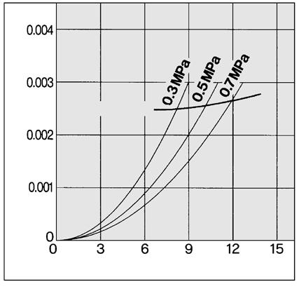
8 MG Series Flow Rate Characteristics (Representative values) / Select the model under the max. flow capacity line. Note) Compressed air over max. flow capacity line in the table below may not meet the specifications of the product. MG150C MG450C MG850 capacity line capacity line capacity line ir flow rate (L/min (NR)) ir flow rate (L/min (NR)) ir flow rate (m 3 /min (NR)) MG250C MG550C capacity line capacity line ir flow rate (L/min (NR)) ir flow rate (L/min (NR)) MG350C capacity line MG50 capacity line ir flow rate (L/min (NR)) ir flow rate (L/min (NR)) 2
 and O-ring (1 pc.")
9 Water Separator MG Series Construction MG150C to 550C, MG50 Component Parts No. Description Material Note Replacement Parts No. Description Material 4 Element assembly Resin, others pplicable model Except option F For option F MG150C MG-EL150 MG-EL150-F Element assembly: With gasket (1 pc.) and O-ring (1 pc.) Refer to page 280 for replacement of auto drain. Maximum Flow Capacity Line capacity (m 3 /min (NR)) Body q r w Housing (Case) Sight glass luminum alloy luminum alloy Tempered glass e Inner/outer surface coating MG250C MG-EL250 MG-EL250-F MG850 MG350C MG-EL350 MG-EL350-F Note) The figure shows the drain cock specification. Note) Sight glass is indicated in the figure for easy understanding of component parts. However, it differs from the actual construction. Refer to dimensions on pages 212 to 214 for details. Model MG450C MG-EL450 MG-EL450-F Model Selection MG550C MG-EL550 MG-EL550-F MG50 MG-EL50 MG850 MG-EL850 Select a model in accordance with the following procedure taking the inlet pressure and the max. flow capacity into consideration. (Example) Inlet pressure: 0. MPa capacity: 5 m 3 /min (NR) 1. Obtain the intersecting point of inlet pressure and max. flow capacity in the graph. 2. The MG50 is obtained when the max. flow capacity line is above the intersecting point in the graph. Note) Make sure to select a model that has the max. flow capacity line above the obtained intersecting point. With a model that has the max. flow capacity line below the obtained intersecting point, the flow rate will be exceeded, thus leading to a problem such as being unable to satisfy the specifications. H HW T B G K MG FF M MD MH ME MF D D Inlet pressure (MPa) 211
10 MG Series Dimensions MG150C to 550C P Q R S uto drain C: With auto drain (N.C.) D: With auto drain (N.O.) uto drain F O Color of drain cock Gray: N.C. Black: N.O. 34 One-touch fitting Thread type Rc, G: ø Thread type NPT: ø3/8 K U T D I L M øv Bracket (ccessory) N Combination of D: With auto drain (N.O.) and H: For medium air pressure uto drain H C J E B 2 Port size Note) 1/4 female threaded The same thread type is used for the and. Note) 23 for MG250C Width across flats 17 Option J: guide 1/4 female threaded G Maintenance space M5 Note) The figure shows the drain cock specification. guide Width across flats 24 1/4 female threaded The same thread type is used for the and. Model MG150C MG250C MG350C MG450C MG550C Port size 1/8, 1/4 1/4, 3/8 3/8, 1/2 1/2, 3/4 3/4, B C D E F G 15 H I 5 J K T 7 Bracket related dimensions U L M V N O P 70 Q R (mm) S
11 Water Separator MG Series Dimensions MG50 uto drain D: With auto drain (N.O.) uto drain cock: Black 34 H HW T One-touch fitting Thread type Rc, G: ø Thread type NPT: ø3/8 B 10 Option J: guide 1/4 female threaded Bracket (ccessory) 85 G K guide MG x Port size 1, 1 1 /2 female threaded Width across flats 24 1/4 female threaded The same thread type is used for the and. FF M MD MH ME MF 23 Maintenance space M5 D Note) The figure shows the drain cock specification. D 213
 The figure shows the drain cock")
12 MG Series Dimensions MG850 uto drain D: With auto drain (N.O.) () uto drain 3/8 female threaded The same thread type is used for the and Bracket ccessory 348 Drawing of view B View B 30 2 x Port size 11/2, 2 female threaded 41 Maintenance space Rc 3/8 Note) The figure shows the drain cock specification. 214


13 Main Line Filter FF Series RoHS Can remove impurities such as oil, water and foreign matter in compressed air and can improve the function of a dryer in the downstream, extend the replacement period of precision filter element, and prevent trouble with the equipment. Modular connection is possible with FF2C to 22C. (For details, refer to page 2.) FF2C to 22C FF37B, 75B ( cock specifications) (uto drain specifications) Made to Order (For details, refer to page 272.) Caution Be sure to read this before handling the products. Refer to back page 50 for Safety Instructions and pages to 8 for ir Preparation Equipment Precautions. Model Model FF2C FF4C FF8C FF11C FF22C FF37B FF75B FF75 FF125 FF150 FF2 Rated flow Note) (L/min (NR)) Port size 1 8, , , , 3 50(2B) 80(3B) 0(4B) 0(4B) 4 3 4, 1 1, , 2 JIS K FF flange Weight (kg) Note) capacity at 0.7 MPa. capacity varies depending on the operating pressure. Refer to Flow Rate Characteristics (page 218) and Maximum Flow Capacity Line below. Specifications Fluid Max. operating pressure Min. operating pressure Note 2) Proof pressure mbient and fluid temperature Filtration rating Element replacement period ccessory Part No./For FF2C to 22C, FF37B/75B pplicable model FF2C FF4C FF8C FF11C FF22C FF37B FF75B Bracket assembly (with 2 mounting screws) M-BM1 M-BM2 M-BM3 M-BM4 M-BM5 BM5 BM57 ccessory Part No./For FF75 to 2 pplicable model FF75 FF125 FF150 FF2 uto drain with metal case (2 pcs. each) uto drain with resin case (2 pcs. each) Pressure gauge (2 pcs. each) D D G Companion flange (2 pcs. each) 50(2B)JIS K FF flange 80(3B)JIS K FF flange 0(4B)JIS K FF flange nchor bolt (3 pcs. each) I-2S Model Selection Select a model in accordance with the following procedure taking the inlet pressure and the max. flow capacity into consideration. (Example) Inlet pressure: 0. MPa capacity: 5 m 3 /min (NR) 1. Obtain the intersecting point of inlet pressure and max. flow capacity in the graph. 2. The FF37B is obtained when the max. flow capacity line is above the intersecting point in the graph. Compressed air 1.0 MPa Note 1) 0.05 MPa 1.5 MPa 5 to 0 C 3 µm (Filtration efficiency: %) 2 years Note 1) or when pressure drop reached 0.1 MPa Note 1) The maximum operating pressure of the FF75 to FF2 is 0.7 MPa, and the element replacement period is when the pressure drop reaches 0.1 MPa or after 1 year operation. Note 2) With auto drain: 0.1 MPa (N.O. type) or 0.15 MPa (N.C. type) Note) Make sure to select a model that has the max. flow capacity line above the obtained intersecting point. With a model that has the max. flow capacity line below the obtained intersecting point, the flow rate will be exceeded, thus leading to a problem such as being unable to satisfy the specifications. Maximum Flow Capacity Line capacity (m 3 /min (NR)) Inlet pressure (MPa) H HW T B G K MG FF M MD MH ME MF D D 215
14 FF Series FF2C to 22C Options Port size 2 1/8 1/4 3/8 1/2 3/4 1 Thread type Type Nil Rc F G N NPT Port size pplicable size ccessory Description Nil B Bracket 1 1 Bracket is included, (but not assembled). uto Specifications/Option Combinations Nil F H R S U T V Nil Note F FF 22 C Size : ll types of auto drain specifications are available. (including drain guide, J specification) : N.C. auto drain ( C specification) is not available. : Both N.C. and N.O. auto drain ( C, D specification) are not available. H R Note S U T V Note Note Note: Only one drain exhaust method can be selected. : Not available How to Order Made to Order s are only added at the end for Made to Order. Refer to page 272 and later for the contents of Made to Order, How to Order, and the applicable models. Option 3 Multiple options can be selected. Refer to the table on the lower left for the available combinations. Indicate symbols in alphabetical order. Description Nil F Rubber material: FKM H For medium air pressure (1. MPa) J guide 1/4 female threaded 5 R - reversal direction S With differential pressure switch (125 VC, 30 VDC), Note) U With differential pressure switch (30 VDC) T With element service indicator V White vaseline 5 Without a valve function Differential pressure switch is included, (but not assembled). Note) Select U if conformity to the EU directive is required. uto drain 2 3 Description Nil Without auto drain (With drain cock 4 ) C N.C. (Normally closed) port is closed when pressure is not applied. D N.O. (Normally open) port is open when pressure is not applied. 2 Refer to page 25 for proper use of the auto drain. (Only one auto drain specification can be selected.) 3 Refer to the table on the left for the available combinations of the auto drain specifications and options. 4 When the option J is selected, the auto drain and drain cock are not available. F: Rubber material: FKM FKM is used for the parts such as O-ring and gasket. H: For medium air pressure (1. MPa) Can be used up to 1. MPa at maximum. J: guide 1/4 female threaded Pipe threaded connection for the drain exhaust port 1/4 female thread B R: - reversal direction Flow direction: Right to left ir flow is changed to right to left. (Flow direction of the standard: Left to right) T: With element service indicator Pressure drop 0.1 MPa Clogging of the element can be observed visually. V: White vaseline The body/housing is degreased, and the grease used for the parts requiring lubrication has been changed to white vaseline. 21 S: With differential pressure switch (with indicator) Clogging of the element can be observed visually or with an electrical signal. The rated contact voltage is different from U. Max. contact capacity: V C, W DC Rated contact voltage (max. operating current): 125 V C (0.08 ), 30 V DC (0.33 ) Reed switch U: With differential pressure switch (with indicator) Clogging of the element can be observed visually or with an electrical signal. The rated contact voltage is different from S. Max. contact capacity: W DC Rated contact voltage (max. operating current): 30 V DC (0.33 ) Reed switch
15 Main Line Filter FF Series FF37B, FF37B/75B75B 14 FF75 to FF 37 B Size Thread type Type Nil Rc F G N NPT Port size Port size pplicable size How to Order Option 2 Multiple options can be selected. Refer to the table below for the available combinations. Indicate symbols in alphabetical order. Description Nil J guide 1 4 female threaded 5 R - reversal direction T With element service indicator 5 Without a valve function uto drain 2 Description Nil Without auto drain (With drain cock 3 ) D N.O. (Normally open) port is open when pressure is not applied. 2 Refer to the following table for the available combinations of the auto drain specifications and options. 3 When the option J is selected, the auto drain and drain cock are not available. 4 Body size 75B is equipped with a ball valve (Rc 3/8). Mount a piping adapter -P0 (page 27) to the ball valve if NPT 3/8 female threaded is required. uto Specifications/Option Combinations : vailable : Not available uto drain specifications/option uto drain specifications Option pplicable model D J R T FF37B FF75B uto drain specifications Option N.O. auto drain guide reversal direction D J R With element service indicator T Port size 50(2B) JIS K FF flange 80(3B) JIS K FF flange 0(4B) JIS K FF flange ccessory Description Nil B Bracket 1 1 Bracket is included, (but not assembled). FF 75 Size Port size pplicable size uto drain (ccessory) Description Nil Without auto drain D With metal case (2 pcs. each) P With resin case (2 pcs. each) Made to Order s are only added at the end for Made to Order. Refer to page 272 and later for the contents of Made to Order, How to Order, and the applicable models. Made to Order s are only added at the end for Made to Order. Refer to page 272 and later for the contents of Made to Order, How to Order, and the applicable models. nchor bolt (ccessory) Description Nil Without anchor bolt L nchor bolt (3 pcs. each) Companion flange (ccessory) Description Nil Without companion flange F Companion flange (2 pcs. each) Pressure gauge (ccessory) Description Nil Without pressure gauge G Pressure gauge (2 pcs. each) 217 H HW T B G K MG FF M MD MH ME MF D D
/select the")


) ir flow rate (L/min (NR)) ir")

) ir flow")
) FF11C FF2 capacity line")
) ir flow rate (m 3 /min (NR))")
16 FF Series Flow Rate Characteristics (Representative values)/select the model under the max. flow capacity line. (Element oil saturation) Note) Compressed air over max. flow capacity line in the table below may not meet the specifications of the product. FF2C FF22C FF75 capacity line capacity line capacity line ir flow rate (L/min (NR)) ir flow rate (L/min (NR)) ir flow rate (m 3 /min (NR)) FF4C FF37B FF125 capacity line capacity line capacity line ir flow rate (L/min (NR)) ir flow rate (L/min (NR)) ir flow rate (m 3 /min (NR)) FF8C FF75B FF150 capacity line capacity line capacity line ir flow rate (L/min (NR)) ir flow rate (m 3 /min (NR)) ir flow rate (m 3 /min (NR)) FF11C FF2 capacity line capacity line 218 ir flow rate (L/min (NR)) ir flow rate (m 3 /min (NR))
17 Main Line Filter FF Series Construction FF2C to 22C, FF37B FF75B q Replacement Parts No. Description Material 4 r w Element assembly Cotton paper, others Element assembly: With gasket (1 pc.) and O-ring (1 pc.) Refer to page 280 for replacement of auto drain. FF75 to 2 ( side) Gauge port pplicable model Except option F For option F FF2C FF-EL2B FF-EL2B-F Component Parts No. Description Material Note Body Housing (Case) Sight glass luminum alloy luminum alloy Tempered glass e Inner/outer surface coating FF4C FF-EL4B FF-EL4B-F FF8C FF-EL8B FF-EL8B-F Note) The figure shows the drain cock specification. Note) Sight glass is indicated in the figure for easy understanding of component parts. However, it differs from the actual construction. Please refer to pages 2 through to 222 for details. Model FF11C FF-EL11B FF-EL11B-F FF22C FF-EL22B FF-EL22B-F FF37B FF-EL37B FF75B FF-EL75B H HW T B G K MG FF M MD MH ME MF D D Gauge port ( side) Component Parts No. Description 1 Case 2 Cover Material Carbon steel Carbon steel Note Replacement Parts No. Description Material Qty. 3 Element 4 Seal NBR 1 1 Model FF75 FF125 FF150 FF2 EC N EC N EC00-003N L-33S L-34S L-35S 21
18 FF Series Dimensions FF2C to 22C P Q uto drain C: With auto drain (N.C.) D: With auto drain (N.O.) uto drain F O 2 x port size S, U: With differential pressure switch (with indicator) Y Z T: With element service indicator W X R S Color of drain cock Gray: N.C. Black: N.O. One-touch fitting Thread type Rc, G: ø Thread type NP: ø3/8 Combination of D: With auto drain (N.O.) and H: For medium air pressure 34 J K U T D I L M øv Bracket (ccessory) N uto drain Note) 23 for FF4C Note) Width across flats 17 1/4 female threaded The same thread type is used for the and. H C E B Option J: guide 1/4 female threaded guide Width across flats 24 1/4 female threaded The same thread type is used for the and. G Maintenance space M5 Note) The figure shows the drain cock specification. Model FF2C FF4C FF8C FF11C FF22C 2 Port size 1/8, 1/4 1/4, 3/8 3/8, 1/2 1/2, 3/4 3/4, B C D E F G Bracket related dimensions 15 H I J K T 7 U 7 L M 7 V N O 54 P 70 Q 2 R 4.5 S 1. (mm) Element Differential service pressure indicator related switch related dimensions dimensions W 24 X 37 Y 32 Z
19 Main Line Filter FF Series Dimensions FF37B uto drain D: With auto drain (N.O.) uto drain H HW 12 cock: Black T One-touch fitting Thread type Rc, G: ø Thread type NPT: ø3/8 34 Option B J: guide 1/4 female threaded Bracket (ccessory) 85 guide G K Width across flats 24 1/4 female threaded The same thread type is used for the and. T: With element service indicator MG FF M x port size 1, 1 1 /2 female threaded MD MH ME MF 23 Maintenance space M5 D Note) The figure shows the drain cock specification. D 221
 58 41 uto drain Rc 3/8 23 Maintenance space Note) The figure shows the drain cock specification. 3/8 female threaded The same thread type is used for the and.")
JISK FF flange 80(3B)JISK FF flange 0(4B)JISK FF flange 0 (8B) 0 (8B) 250 (B) 380 380 450 1125 1125 1178 35 35 80 505 505 540 25 25 25 184 184 23 FF2 0(4B)JISK FF")
20 FF Series Dimensions FF75B Bracket ccessory () View B x port size 1 /2, 2 female threaded Drawing of view B 44 uto drain D: With auto drain (N.O.) uto drain Rc 3/8 23 Maintenance space Note) The figure shows the drain cock specification. 3/8 female threaded The same thread type is used for the and. FF75 to 2 3 x ø holes For foundation bolt Option T: With element service indicator Label N5: Pressure outlet ( side) N: Pressure outlet ( side) ORIENTTION 222 (mm) Model Port size (Flange) ø B C D E F G FF75 FF125 FF150 50(2B)JISK FF flange 80(3B)JISK FF flange 0(4B)JISK FF flange 0 (8B) 0 (8B) 250 (B) FF2 0(4B)JISK FF flange 300 (12B)
21 Mist Separator M Series RoHS Can remove oil mist in compressed air and separate and remove particles such as rust or carbon of more than 0.3 µm. Modular connection is possible with M150C to 550C. (For details, refer to page 2.) M150C to 550C ( cock specifications) M50/850 (uto drain specifications) Made to Order (For details, refer to page 272.) Model Model Note) Rated flow (L/min (NR)) Port size Weight (kg) M150C 300 M250C 750 M350C 1500 M450C 20 M550C 3700 M M , , , , , 1 1, , Note) Maximum flow capacity at 0.7 MPa. Maximum flow capacity varies depending on the operating pressure. Refer to Flow Rate Characteristics (page 22) and Max. Flow Capacity Line (page 227) below. Note) Refer to Made to Order (page 27) for high flow type of M850 or more. Specifications Fluid Max. operating pressure Min. operating pressure 1 Proof pressure mbient and fluid temperature Nominal filtration rating Oil mist density at outlet Element replacement period 1 With auto drain: 0.1 MPa (N.O. type) or 0.15 MPa (N.C. type) 2 When the inlet oil mist density is 30 mg/m 3 (NR). ccessory Part No. pplicable model Bracket assembly (with 2 mounting screws) Caution Compressed air 1.0 MPa 0.05 MPa 1.5 MPa 5 to 0 C 0.3 µm (Filtration efficiency:.%) Max. 1 mg/m 3 (NR) ( 0.8 ppm) 2 2 years or when pressure drop reached 0.1 MPa M150C M250C M350C M450C M550C M50 M850 M-BM1 M-BM2 M-BM3 M-BM4 M-BM5 BM5 BM57 Be sure to read this before handling the products. Refer to back page 50 for Safety Instructions and pages to 8 for ir Preparation Equipment Precautions. H HW T B G K MG FF M MD MH ME MF D D 223
22 M Series M150C to 550C uto Specifications/Option Combinations : ll types of auto drain specifications are available. (including drain guide, J specification) : N.C. auto drain ( C specification) is not available. : Both N.C. and N.O. auto drain ( C, D specification) are not available. Nil F H R S U T V Nil Note F H R Note S U T V Note Note Note: Only one drain exhaust method can be selected. : Not available Options M 550 C Size Thread type Type Nil Rc F G N NPT Port size Port pplicable size size /8 1/4 3/8 1/2 3/4 1 ccessory Description Nil B Bracket 1 1 Bracket is included, (but not assembled). How to Order Made to Order s are only added at the end for Made to Order. Refer to page 272 and later for the contents of Made to Order, How to Order, and the applicable models. Option 3 Multiple options can be selected. Refer to the table on the lower left for the available combinations. Indicate symbols in alphabetical order. Description Nil F Rubber material: FKM H For medium air pressure (1. MPa) J guide 1/4 female threaded 5 R - reversal direction S With differential pressure switch (125 VC, 30 VDC), Note) U With differential pressure switch (30 VDC) T Element service indicator V White vaseline 5 Without a valve function Differential pressure switch is included, (but not assembled). Note) Select U if conformity to the EU directive is required. uto drain 2 3 Description Nil Without auto drain (With drain cock 4 ) C N.C. (Normally closed) port is closed when pressure is not applied. D N.O. (Normally open) port is open when pressure is not applied. 2 Refer to page 25 for proper use of the auto drain. (Only one auto drain specification can be selected.) 3 Refer to the table on the left for the available combinations of the auto drain specifications and options. 4 When the option J is selected, the auto drain and drain cock are not available. F: Rubber material: FKM FKM is used for the parts such as O-ring and gasket. H: For medium air pressure (1. MPa) Can be used up to 1. MPa at maximum. J: guide 1/4 female threaded Pipe threaded connection for the drain exhaust port 1/4 female threaded B R: - reversal direction Flow direction: Right to left (Flow direction of the standard: Left to right) T: With element service indicator Pressure drop 0.1 MPa Clogging of the element can be observed visually. V: White vaseline The body/housing is degreased, and the grease used for the parts requiring lubrication has been changed to white vaseline. 224 S: With differential pressure switch (with indicator) Clogging of the element can be observed visually or with an electrical signal. The rated contact voltage is different from U. Max. contact capacity: V C, W DC Rated contact voltage (max. operating current): 125 VC (0.08 ), 30 VDC (0.33 ) Reed switch U: With differential pressure switch (with indicator) Clogging of the element can be observed visually or with an electrical signal. The rated contact voltage is different from S. Max. contact capacity: W DC Rated contact voltage (max. operating current): 30 VDC (0.33 ) Reed switch
23 Mist Separator M Series M50/850 Options M 50 Size Port size Thread type Type Nil Rc F G N NPT Port size pplicable size ccessory Description Nil B Bracket 1 1 Bracket is included, (but not assembled). How to Order Option 3 Multiple options can be selected. Refer to the table below for the available combinations. Indicate symbols in alphabetical order. Description Nil J guide 1 4 female threaded 5 R - reversal direction T With element service indicator 5 Without a valve function uto Specifications/Option Combinations uto drain specifications/option uto drain specifications N.O. auto drain guide 1 4 Option - reversal direction With element service indicator T J: guide 1/4 female threaded Pipe threaded connection for the drain exhaust port 1/4 female threaded uto drain 2 Description Nil Without auto drain (With drain cock 3 4 ) D N.O. (Normally open) port is open when pressure is not applied. 2 Refer to the following table for the available combinations of the auto drain specifications and options. 3 When the option J is selected, the auto drain and drain cock are not available. 4 Body size 850 is equipped with a ball valve (Rc 3/8). Mount a piping adapter -P0 (page 27) to the ball valve if NPT 3/8 female threaded is required. D J R R: - reversal direction Flow direction: Right to left (Flow direction of the standard: Left to right) Made to Order s are only added at the end for Made to Order. Refer to page 272 and later for the contents of Made to Order, How to Order, and the applicable models. uto drain specifications Option D J R T : vailable : Not available pplicable model M50 M850 T: With element service indicator Pressure drop 0.1 MPa Clogging of the element can be observed visually. H HW T B G K MG FF M MD MH ME MF D D 225
 /Select the model under")
 Note) Compressed air")


) ir flow rate (m 3 /min (NR))")
) 22")
24 M Series Flow Rate Characteristics (Representative values) /Select the model under the max. flow capacity line. (Element oil saturation) Note) Compressed air over max. flow capacity line in the table below may not meet the specifications of the product. M150C M450C M850 capacity line capacity line capacity line ir flow rate (L/min (NR)) ir flow rate (L/min (NR)) ir flow rate (m 3 /min (NR)) M250C M550C capacity line capacity line ir flow rate (L/min (NR)) ir flow rate (L/min (NR)) M350C M50 capacity line capacity line ir flow rate (L/min (NR)) ir flow rate (L/min (NR)) 22
 Sight glass luminum alloy luminum alloy Tempered glass Replacement Parts No. Description Material 4 Element assembly: With gasket (1 pc.")
25 Mist Separator M Series Construction M150C to 550C, M50 M850 q Component Parts No. Description Material Note Body Housing (Case) Sight glass luminum alloy luminum alloy Tempered glass Replacement Parts No. Description Material 4 Element assembly: With gasket (1 pc.) and O-ring (1 pc.) Refer to page 280 for replacement of auto drain. Maximum Flow Capacity Line Maximum flow capacity (m 3 /min (NR)) r w Element assembly Glass fiber, others pplicable model Except option F For option F M150C M-EL150 M-EL150-F e Inner/outer surface coating M250C M-EL250 M-EL250-F M350C M-EL350 M-EL350-F Note) The figure shows the drain cock specification. Note) Sight glass is indicated in the figure for easy understanding of component parts. However, it differs from the actual construction. Refer to dimensions on pages 228 through to 230 for details. Model M450C M-EL450 M-EL450-F Model Selection M550C M-EL550 M-EL550-F M50 M-EL50 M850 M-EL850 Select a model in accordance with the following procedure taking the inlet pressure and the maximum flow capacity into consideration. (Example) Inlet pressure: 0. MPa Maximum flow capacity: 5 m 3 /min (NR) 1. Obtain the intersecting point of inlet pressure and Maximum flow capacity in the graph. 2. The M50 is obtained when the max. flow capacity line is above the intersecting point in the graph. Note) Make sure to select a model that has the max. flow capacity line above the obtained intersecting point. With a model that has the max. flow capacity line below the obtained intersecting point, the flow rate will be exceeded, thus leading to a problem such as being unable to satisfy the specifications. H HW T B G K MG FF M MD MH ME MF D D Inlet pressure (MPa) 227
26 Z M Series Dimensions M150C to 550C P Q uto drain C: With auto drain (N.C.) D: With auto drain (N.O.) uto drain F R O S Color of drain cock Gray: N.C. Black: N.O. One-touch fitting Thread type Rc, G: ø Thread type NPT: ø3/8 Combination of D: With auto drain (N.O.) and H: For medium air pressure 34 uto drain H C K J U G Maintenance space T D I L M øv Bracket (ccessory) Width across flats 24 1/4 female threaded The same thread type is used for the and. S, U: With differential pressure switch (with indicator) Y T: With element service indicator W X E B M5 Note) The figure shows the drain cock specification. N 2 x Port size Note) 1/4 female threaded The same thread type is used for the and. Note) 23 for M250C Option J: guide 1/4 female threaded guide Width across flats 17 Model M150C M250C M350C M450C M550C 228 Port size 1/8, 1/4 1/4, 3/8 3/8, 1/2 1/2, 3/4 3/4, B C D E F G Bracket related dimensions 15 H I J K T 7 U 7 L M 7 V N O 54 P 70 Q 2 R 4.5 S 1. (mm) Element Differential service pressure indicator related switch related dimensions dimensions W 24 X 37 Y 32 Z
27 Mist Separator M Series Dimensions M50 uto drain D: With auto drain (N.O.) uto drain cock: Black H HW T One-touch fitting Thread type Rc, G: ø Thread type NPT: ø3/8 34 Option B J: guide 1/4 female threaded Bracket (ccessory) x Port size 1, 1 1 /2 female threaded guide Width across flats 24 T: With element service indicator 55 1/4 female threaded The same thread type is used for the and. 37 G K MG FF M MD MH ME MF 23 Maintenance space M5 D Note) The figure shows the drain cock specification. D 22
28 M Series Dimensions M Bracket (ccessory) 180 () View B x port size 1 /2, 2 female threaded Drawing of view B 44 uto drain D: With auto drain (N.O.) uto drain Maintenance space Rc 3/8 Note) The figure shows the drain cock specification. 3/8 female threaded The same thread type is used for the and. Option T: With element service indicator 230
29 Micro Mist Separator MD Series RoHS Can separate and remove aerosol state oil mist in compressed air and remove particles such as carbon or dust of more than 0.01 µm. Use this product as a pre-filter for compressed air for precision instruments or clean room requiring higher clean air. Modular connection is possible with MD150C to 550C. (For details, refer to page 2.) MD150C to 550C ( cock specifications) MD50/850 (uto drain specifications) Made to Order (For details, refer to page 272.) Model Note) Rated flow (L/min (NR)) Port size Model Weight (kg) MD150C MD250C MD350C MD450C MD550C MD50 MD , , , , , Note) capacity at 0.7 MPa. capacity varies depending on the operating pressure. Refer to Flow Rate Characteristics (page 234) and Maximum Flow Capacity Line (page 233). Model/Free Standing Type Model Rated flow (L/min (NR)) Port size Weight (kg) Specifications Fluid Max. operating pressure Note 1) Min. operating pressure Proof pressure mbient and fluid temperature Filtration rating Oil mist density at outlet Element replacement period MD (2B), 80(3B), 0(4B)JIS K FF flange 2 Note 1) With auto drain: 0.1 MPa (N.O. type) or 0.15 MPa (N.C. type) Note 2) When the inlet oil mist density is 30 mg/m 3 (NR). Note 3) 0.7 MPa for free standing type ccessory Part No. pplicable model Bracket assembly (with 2 mounting screws) Caution 1, , 2 MD (4B), 150(B)JIS K FF flange 430 Compressed air Note 3) 1.0 MPa 0.05 MPa 1.5 MPa 5 to 0 C 0.01 µm (Filtration efficiency:.%) Max. 0.1 mg/m 3 (NR) Note 2) (Before saturated with oil, less than 0.01 mg/m 3 (NR) ppm) 2 years (1 year for free standing type) or when pressure drop reached 0.1 MPa MD150C MD250C MD350C MD450C MD550C MD50 MD850 M-BM1 M-BM2 M-BM3 M-BM4 M-BM5 BM5 BM57 Be sure to read this before handling the products. Refer to back page 50 for Safety Instructions and pages to 8 for ir Preparation Equipment Precautions. H HW T B G K MG FF M MD MH ME MF D D 231
.")
30 MD Series MD150C to 550C Size Options Thread type Type Nil Rc F G N NPT Port size Port pplicable size size /8 1/4 3/8 1/2 3/4 1 ccessory Description Nil B Bracket 1 1 Bracket is included, (but not assembled). uto Specifications/Option Combinations Nil F H R S U T V Nil Note MD 550 C : ll types of auto drain specifications are available. (including drain guide, J specification) : N.C. auto drain ( C specification) is not available. : Both N.C. and N.O. auto drain ( C, D specification) are not available. F H R Note S U T V Note Note Note: Only one drain exhaust method can be selected. : Not available How to Order Made to Order s are only added at the end for Made to Order. Refer to page 272 and later for the contents of Made to Order, How to Order, and the applicable models. Option 3 Multiple options can be selected. Refer to the table on the lower left for the available combinations. Indicate symbols in alphabetical order. Description Nil F Rubber material: FKM H For medium air pressure (1. MPa) J guide 1/4 female thread 5 R - reversal direction S With differential pressure switch (125 VC, 30 VDC) U With differential pressure switch (30 VDC) T With element service indicator V White vaseline 5 Without a valve function Differential pressure switch is included, (but not assembled). Note) Select U if conformity to the EU directive is required., Note) uto drain 2 3 Description Nil Without auto drain (With drain cock 4 ) C N.C. (Normally closed) port is closed when pressure is not applied. D N.O. (Normally open) port is open when pressure is not applied. 2 Refer to page 25 for proper use of the auto drain. (Only one auto drain specification can be selected.) 3 Refer to the table on the left for the available combinations of the auto drain specifications and options. 4 When the option J is selected, the auto drain and drain cock are not available. F: Rubber material: FKM FKM is used for the parts such as O-ring and gasket. H: For medium air pressure (1. MPa) Can be used up to 1. MPa at maximum. J: guide 1/4 female threaded Pipe threaded connection for the drain exhaust port 1/4 female threaded B R: - reversal direction Flow direction: Right to left (Flow direction of the standard: Left to right) T: With element service indicator Pressure drop 0.1 MPa Clogging of the element can be observed visually. V: White vaseline The body/housing is degreased, and the grease used for the parts requiring lubrication has been changed to white vaseline. 232 S: With differential pressure switch (with indicator) Clogging of the element can be observed visually or with an electrical signal. The rated contact voltage is different from U. Max. contact capacity: V C, W DC Rated contact voltage (max. operating current): 125 V C (0.08 ), 30 V DC (0.33 ) Reed switch U: With differential pressure switch (with indicator) Clogging of the element can be observed visually or with an electrical signal. The rated contact voltage is different from S. Max. contact capacity: W DC Rated contact voltage (max. operating current): 30 V DC (0.33 ) Reed switch
. uto drain 2 Description Without auto drain (With drain cock 3 4 ) N.O.")
.")
31 Micro Mist Separator MD Series MD50/ Nil D MD 50 Size Port size Thread type Type Nil Rc F G N NPT Port size pplicable size Free standing type MD Size Model Selection 00 ccessory Description Nil B Bracket 1 1 Bracket is included, (but not assembled). uto drain 2 Description Without auto drain (With drain cock 3 4 ) N.O. (Normally open) port is open when pressure is not applied. 2 Refer to the table on the right for the available combinations of the auto drain specifications and options. 3 When the option J is selected, the auto drain and drain cock are not available. 4 Body size 850 is equipped with a ball valve (Rc 3/8). Mount a piping adapter -P0 (page 27) to the ball valve if NPT 3/8 female threaded is required. MD, uto drain Description 00 With manual drain cock With auto drain uto drain is N.O. (Normally open). port is open when pressure is not applied. Port size Select a model in accordance with the following procedure taking the inlet pressure and the max. flow capacity into consideration. (Example) Inlet pressure: 0. MPa capacity: 5 m 3 /min (NR) 1. Obtain the intersecting point of inlet pressure and max. flow capacity in the graph. 2. The MD50 is obtained when the max. flow capacity line is above the intersecting point in the graph. Note) Make sure to select a model that has the max. flow capacity line above the obtained intersecting point. With a model that has the max. flow capacity line below the obtained intersecting point, the flow rate will be exceeded, thus leading to a problem such as being unable to satisfy the specifications. How to Order Made to Order s are only added at the end for Made to Order. Refer to page 272 and later for the contents of Made to Order, How to Order, and the applicable models. Option 3 Multiple options can be selected. Refer to the table below for the available combinations. Indicate symbols in alphabetical order. Description Nil J guide 1 4 female threaded 5 R - reversal direction T With element service indicator 5 Without a valve function uto Specifications/ Option Combinations : vailable : Not available uto drain uto drain specifications/option specifications Option pplicable model D J R T MD50 MD850 uto drain specifications N.O. auto drain guide 1 4 D J Option - reversal direction R With element service indicator T Port size 50(2B)JIS K FF flange 80(3B)JIS K FF flange 0(4B)JIS K FF flange 150(B)JIS K FF flange pplicable size MD 0 MD 0 Maximum Flow Capacity Line capacity (m 3 /min (NR)) MD MD MD850 MD50 MD550C MD450C MD350C MD250C H HW T B G K MG FF M MD MH ME MF D D MD150C Inlet pressure (MPa) 233

32 MD Series Flow Rate Characteristics (Representative values)/select the model under the max. flow capacity line. ( Element oil saturation Initial condition) Note) Compressed air over max. flow line in the table below may not meet the specifications of the product. MD150C MD250C MD350C capacity line capacity line capacity line ir flow rate (L/min (NR)) ir flow rate (L/min (NR)) ir flow rate (L/min (NR)) MD450C MD550C MD50 capacity line capacity line capacity line ir flow rate (L/min (NR)) ir flow rate (L/min (NR)) ir flow rate (L/min (NR)) MD850 MD MD capacity line capacity line capacity line ir flow rate (m 3 /min (NR)) ir flow rate (m 3 /min (NR)) ir flow rate (m 3 /min (NR)) 234
33 Micro Mist Separator MD Series Construction MD150C to 550C, MD50 q MD850 Replacement Parts No. Description Material 4 r w Element assembly Glass fiber, others MD, 0 pplicable model Except option F For option F MD150C MD-EL150 MD-EL150-F Element assembly: With gasket (1 pc.) and O-ring (1 pc.) Refer to page 280 for replacement of auto drain. Component Parts No. Description Material Note Body Housing (Case) Sight glass luminum alloy luminum alloy Tempered glass Inner/outer surface coating e Details of element mounting part MD250C MD-EL250 MD-EL250-F MD350C MD-EL350 MD-EL350-F Component Parts/Material No. 1 Case 2 Cover Description Replacement Parts No. Description 3 Element 4 Seal 5 Seal Model MD450C MD-EL450 MD-EL450-F MD550C MD-EL550 MD-EL550-F Material NBR NBR Note) The figure shows the drain cock specification. Note) Sight glass is indicated in the figure for easy understanding of component parts. However, it differs from the actual construction. Refer to dimensions on pages 23 through to 23 for details. MD50 MD-EL50 Model MD, Carbon steel Carbon steel Model MD MD pcs pcs pcs pcs. O.D112 x I.D0 x T3 3 pcs. MD850 MD-EL850 O.D112 x I.D0 x T3 5 pcs. H HW T B G K MG FF M MD MH ME MF D D Gasket V#500 L-3S L-31S 7 O-ring NBR K pcs. K pcs. 235
34 Z MD Series Dimensions MD150C to 550C P Q uto drain C: With auto drain (N.C.) D: With auto drain (N.O.) uto drain F R O S Color of drain cock Gray: N.C. Black: N.O. One-touch fitting Thread type Rc, G: ø Thread type NPT: ø3/8 Combination of D: With auto drain (N.O.) and H: For medium air pressure 34 H C K J U G Maintenance space T D I L M øv Bracket (ccessory) 1/4 female threaded The same thread type is used for the and. S, U: With differential pressure switch (with indicator) Y T: With element service indicator W X E B M5 Note) The figure shows the drain cock specification. N 2 x port size uto drain Note) 1/4 female threaded The same thread type is used for the and. Note) 23 for MD250C Option J: guide 1/4 female threaded guide Width across flats 24 Width across flats 17 Model MD150C MD250C MD350C MD450C MD550C 23 Port size 1/8, 1/4 1/4, 3/8 3/8, 1/2 1/2, 3/4 3/4, B C D E F G Bracket related dimensions 15 H I J K T 7 U 7 L M 7 V N O 54 P 70 Q 2 R 4.5 S 1. (mm) Element Differential service pressure indicator related switch related dimensions dimensions W 24 X 37 Y 32 Z
35 Micro Mist Separator MD Series Dimensions MD Maintenance space Bracket (ccessory) M5 Note) The figure shows the drain cock specification x port size 1, 11/2 female threaded uto drain D: With auto drain (N.O.) uto drain cock: Black One-touch fitting Thread type Rc, G: ø Thread type NPT: ø3/8 Option J: guide 1/4 female threaded guide Width across flats 24 T: With element service indicator /4 female threaded The same thread type is used for the and. H HW T B G K MG FF M MD MH ME MF D D 237
 58 uto drain Rc 3/8 23 Maintenance space 3/8 female threaded The same thread type is used for the and. Note) The figure shows the drain cock specification.")
36 MD Series Dimensions MD () Bracket ccessory 42 3 View B x port size 11/2, 2 female threaded Drawing of view B uto drain D: With auto drain (N.O.) 58 uto drain Rc 3/8 23 Maintenance space 3/8 female threaded The same thread type is used for the and. Note) The figure shows the drain cock specification. Option T: With element service indicator 238
, 150(B)JIS K FF flange 870 øb 50 745 øc 400 550 D 300 300 E 13 1380 F 1480 1 G 1585 1740 (mm) H 24 24 K MG FF M MD MH ME MF D D")
37 Micro Mist Separator MD Series Dimensions MD, H HW ORIENTTION T 3 x øh holes Label B G Model MD MD Port size (Flange) 50(2B), 80(3B), 0(4B)JIS K FF flange 7 0(4B), 150(B)JIS K FF flange 870 øb øc D E F G (mm) H K MG FF M MD MH ME MF D D 23

38 Micro Mist Separator with Pre-filter MH Series RoHS Can separate and remove aerosol state oil mist in compressed air and remove particles such as carbon or dust of more than 0.01 µm. Use this product as a pre-filter for compressed air for precision instruments or clean room requiring higher clean air. The M series and MD series have been integrated to achieve a reduction in installation space and in piping labor. Modular connection is possible with MH150C to 550C. (For details, refer to page 2.) MH150C to 550C ( cock specifications) MH50/850 (uto drain specifications) Made to Order (For details, refer to page 272.) Model Model MH150C MH250C MH350C MH450C MH550C MH50 MH850 Note) Rated flow (L/min (NR)) Port size Weight (kg) 1 8, , , , , Note) capacity at 0.7 MPa. capacity varies depending on the operating pressure. Refer to Flow Rate Characteristics (page 244) and Maximum Flow Capacity Line below. Specifications Fluid Max. operating pressure Min. operating pressure 1 Proof pressure mbient and fluid temperature Nominal filtration density Oil mist density at outlet Element replacement period 1 With auto drain: 0.1 MPa (N.O. type) or 0.15 MPa (N.C. type) 2 When the inlet oil mist density is 30 mg/m 3 (NR). ccessory Part No. pplicable model Bracket assembly (with 2 mounting screws) Model Selection Select a model in accordance with the following procedure taking the inlet pressure and the max. flow capacity into consideration. (Example) Inlet pressure: 0. MPa capacity: 5 m 3 /min (NR) 1. Obtain the intersecting point of inlet pressure and max. flow capacity in the graph. 2. The MH50 is obtained when the max. flow capacity line is above the intersecting point in the graph. Note) Make sure to select a model that has the max. flow capacity line above the obtained intersecting point. With a model that has the max. flow capacity line below the obtained intersecting point, the flow rate will be exceeded, thus leading to a problem such as being unable to satisfy the specifications. Caution Compressed air 1.0 MPa 0.05 MPa 1.5 MPa 5 to 0 C 0.01 µm (Filtration efficiency:.%) Max. 0.1 mg/m 3 (NR) 2 (Before saturated with oil, less than 0.01 mg/m 3 (NR) ppm) 2 years or when pressure drop reached 0.1 MPa MH150C MH250C MH350C MH450C MH550C MH50 MH850 M-BM1 M-BM2 M-BM3 M-BM4 M-BM5 BM5 BM57 Maximum Flow Capacity Line capacity (m 3 /min (NR)) Inlet pressure (MPa) 1, , 2 H HW T B G K MG FF M MD MH ME MF D D Be sure to read this before handling the products. Refer to back page 50 for Safety Instructions and pages to 8 for ir Preparation Equipment Precautions. 241
39 MH Series MH150C to 550C Options Size Thread type Type Nil Rc F G N NPT Port size Port pplicable size size /8 1/4 3/8 1/2 3/4 1 ccessory Description Nil B Bracket 1 1 Bracket is included, (but not assembled). Exhaust Specifications/Option Combinations Nil F H R S U T V Nil Note MH 550 C : ll types of drain exhaust specifications are available. (including drain guide, J specification) : N.C. auto drain ( C specification) is not available. : Both N.C. and N.O. auto drain ( C, D specification) are not available. F H R Note S U T V Note Note Note: Only one drain exhaust method can be selected. : Not available How to Order Made to Order s are only added at the end for Made to Order. Refer to page 272 and later for the contents of Made to Order, How to Order, and the applicable models. Option 3 Multiple options can be selected. Refer to the table on the lower left for the available combinations. Indicate symbols in alphabetical order. Description Nil F Rubber material: FKM H For medium air pressure (1. MPa) J guide 1/4 female threaded 5 R - reversal direction S With differential pressure switch (125 VC, 30 VDC) U With differential pressure switch (30 VDC) T With element service indicator V White vaseline 5 Without a valve function Differential pressure switch is included, (but not assembled). Note) Select U if conformity to the EU directive is required., Note) uto drain 2 3 Description Nil Without auto drain (With drain cock 4 ) C N.C. (Normally closed) port is closed when pressure is not applied. D N.O. (Normally open) port is open when pressure is not applied. 2 Refer to page 25 for proper use of the auto drain. (Only one auto drain specification can be selected.) 3 Refer to the table on the left for the available combinations of the auto drain specifications and options. 4 When the option J is selected, the auto drain and drain cock are not available. F: Rubber material: FKM FKM is used for the parts such as O-ring and gasket. H: For medium air pressure (1. MPa) Can be used up to 1. MPa at maximum. J: guide 1/4 female threaded Pipe threaded connection for the drain exhaust port 1/4 female threaded B R: - reversal direction Flow direction: Right to left (Flow direction of the standard: Left to right) T: With element service indicator Pressure drop 0.1 MPa Clogging of the element can be observed visually. V: White vaseline The body/housing is degreased, and the grease used for the parts requiring lubrication has been changed to white vaseline. 242 S: With differential pressure switch (with indicator) Clogging of the element can be observed visually or with an electrical signal. The rated contact voltage is different from U. Max. contact capacity: V C, W DC Rated contact voltage (max. operating current): 125 V C (0.08 ), 30 V DC (0.33 ) Reed switch U: With differential pressure switch (with indicator) Clogging of the element can be observed visually or with an electrical signal. The rated contact voltage is different from S. Max. contact capacity: W DC Rated contact voltage (max. operating current): 30 V DC (0.33 ) Reed switch
40 Micro Mist Separator with Pre-filter MH Series MH50/850 MH Size Thread type Type Nil Rc F G N NPT Port size Port size pplicable size ccessory Description Nil B Bracket 1 1 Bracket is included, (but not assembled). How to Order Made to Order s are only added at the end for Made to Order. Refer to page 272 and later for the contents of Made to Order, How to Order, and the applicable models. Option 3 Multiple options can be selected. Refer to the table below for the available combinations. Indicate symbols in alphabetical order. Description Nil J guide 1 4 female threaded 5 R - reversal direction T With element service indicator 5 piping and piping for a stop valve such as ball valve are required. uto drain 2 Description Nil Without auto drain (With drain cock 3 4 ) D N.O. (Normally open) port is open when pressure is not applied. 2 Refer to the following table for the available combinations of the auto drain specifications and options. 3 When the option J is selected, the auto drain and drain cock are not available. 4 Body size 850 is equipped with a ball valve (Rc3/8). Mount a piping adapter -P0 (page 27) to the ball valve if NPT3/8 female threaded is required. uto Specifications/Option Combinations : vailable : Not available uto drain specifications/option uto drain specifications Option pplicable model D J R T MH50 MH850 uto drain specifications Option N.O. auto drain guide reversal direction D J R With element service indicator T H HW T B G K MG FF M MD MH ME MF D D 243
/select the model under the max.")
 Note)")


) ir flow")


41 MH Series Flow Rate Characteristics (Representative values)/select the model under the max. flow capacity line. ( Element oil saturation Initial condition) Note) Compressed air over max. flow capacity line in the table below may not meet the specifications of the product. MH150C MH450C MH850 Inlet air pressure ir pressure Inlet air pressure capacity line capacity line capacity line ir flow rate (L/min (NR)) ir flow rate (L/min (NR)) ir flow rate (m 3 /min (NR)) MH250C MH550C Inlet air pressure ir pressure capacity line capacity line ir flow rate (L/min (NR)) ir flow rate (L/min (NR)) MH350C MH50 Inlet air pressure ir pressure capacity line capacity line ir flow rate (L/min (NR)) ir flow rate (L/min (NR)) 244
42 Micro Mist Separator with Pre-filter MH Series Construction MH150C to 550C, MH50 MH850 q r w Replacement Parts No. Description Material 4 Element assembly Glass fiber, pplicable model Except option F Component Parts No. Description Material Note Body Housing (Case) Sight glass luminum alloy luminum alloy Tempered glass e MH150C MH-EL150 others For option F MH-EL150-F Element assembly: With gasket (1 pc.) and O-ring (1 pc.) Refer to page 280 for replacement of auto drain. Inner/outer surface coating MH250C MH-EL250 MH-EL250-F MH350C MH-EL350 MH-EL350-F Note) The figure shows the drain cock specification. Note) Sight glass is indicated in the figure for easy understanding of component parts. However, it differs from the actual construction. Refer to dimensions on pages 24 through to 248 for details. Model MH450C MH-EL450 MH-EL450-F MH550C MH-EL550 MH-EL550-F MH50 MH-EL50 MH850 MH-EL850 H HW T B G K MG FF M MD MH ME MF D D 245
43 MH Series Dimensions MH150C to 550C P Q uto drain C: With auto drain (N.C.) D: With auto drain (N.O.) uto drain F R O D I Width across flats 24 1/4 female threaded The same thread type is used for the and. S, U: With differential pressure switch (with indicator) Y Z T: With element service indicator W X S Color of drain cock Gray: N.C. Black: N.O. One-touch fitting Thread type Rc, G: ø Thread type NPT: ø3/8 Combination of D: With auto drain (N.O.) and H: For medium air pressure 34 H C K J U G T L M øv Bracket (ccessory) E B N 2 x port size 1/4 female threaded The same thread type is used for the and. Note) 23 for MH250C Option J: guide 1/4 female threaded guide Maintenance space M5 Note) The figure shows the drain cock specification. Model MH150C MH250C MH350C MH450C MH550C 24 Port size 1/8, 1/4 1/4, 3/8 3/8, 1/2 1/2, 3/4 3/4, B C D E F G Bracket related dimensions 15 H I J K T 7 U 7 L M 7 V N O 54 P 70 Q 2 R 4.5 S 1. (mm) Element Differential service pressure indicator related switch related dimensions dimensions W 24 X 37 Y 32 Z
44 Micro Mist Separator with Pre-filter MH Series Dimensions MH50 uto drain D: With auto drain (N.O.) uto drain cock: Black H HW T One-touch fitting Thread type Rc, G: ø Thread type NPT: ø3/8 Option 34 J: guide 1/4 female threaded B Bracket (ccessory) guide Width across flats 24 1/4 female threaded The same thread type is used for the and. T: With element service indicator G K MG FF M MD MH ME Maintenance space 23 M5 2 x port size 1, 11/2 female threaded MF D Note) The figure shows the drain cock specification. D 247
 uto drain 58 23 Rc 3/8 3/8 female threaded The same thread type is used for the and.")
45 MH Series Dimensions MH () Bracket ccessory 42 View B x port size 11/2, 2 female threaded Drawing of view B uto drain D: With auto drain (N.O.) uto drain Rc 3/8 3/8 female threaded The same thread type is used for the and. Maintenance space Option T: With element service indicator 248

46 Super Mist Separator ME Series RoHS Can separate and adsorb aerosol state fine oil particles in compressed air and change the oil lubricating compressed air to oilless air or equivalent. Use this product for filtration of compressed air requiring higher clean air for painting lines, compressed air for clean rooms and/or equipment where oils must be avoided. The replacement time of the element is indicated by a color change. When the element becomes saturated with oil content, a red color spot will begin to appear on the front surface. When the red color spot becomes visible, replace the element immediately. Caution Be sure to use either the M, MD, or MH series as a pre-filter. Modular connection is possible with ME150C to 550C. (For details, refer to page 2.) ME150C to 350C ME450C/550C Model Model ME150C ME250C ME350C ME450C ME550C ME50 ME850 Note) Rated flow (L/min (NR)) Port size Weight (kg) 1 8, , , , , Note) capacity at 0.7 MPa. capacity varies depending on the operating pressure. Refer to Flow Rate Characteristics and Maximum Flow Capacity Line (page 252). Specifications Fluid Max. operating pressure Min. operating pressure Proof pressure mbient and fluid temperature Filtration rating Note 2) Cleanliness at outlet 1, , 2 Compressed air 1.0 MPa 0.05 MPa 1.5 MPa 5 to 0 C 0.01 µm (Filtration efficiency:.%) Less than 0 particles of 0.3 µm or larger per cubic foot [Less than 35 particles per liters (NR)] Max mg/m Oil mist density at outlet 3 (NR) ( ppm) 1. Replace the element when a red color spot occurred on the Note 1) surface. Element replacement period 2. Even if a red color spot does not appear on the surface, the replacement interval for the element is when the pressure drop reaches 0.1 MPa or after two years of operation, whichever comes first. Note 1) Failure to replace the element when the red color spot begins to appear will result in red-pigmented oil content leaking into the secondary side. If immediate element replacement is for some reason not an option, an MF must be installed on the secondary side and the element should be replaced as soon as possible. In such cases, the MF element should be replaced at the same time. Note 2) Depending on the operating conditions, only a miniscule amount of red pigment, which will not affect filtration performance, may leak into the secondary side. Prolonged use under such conditions may result in minimal red-pigmented residue on the interior of the piping on the secondary side. ccessory Part No. pplicable model Bracket assembly (with 2 mounting screws) Caution ME150C ME250C ME350C ME450C ME550C ME50 ME850 M-BM1 M-BM2 M-BM3 M-BM4 M-BM5 BM5 BM57 Be sure to read this before handling the products. Refer to back page 50 for Safety Instructions and pages to 8 for ir Preparation Equipment Precautions. H HW T B G K MG FF M MD MH ME MF D D ME50/850 Made to Order (For details, refer to page 272.) 24 B
47 ME Series ME150C to 550C Size Thread type Type Nil Rc F G N NPT How to Order ME 550 C Option Multiple options can be selected. Indicate symbols in alphabetical order. Description Nil F Rubber material: FKM H For medium air pressure (1. MPa) R - reversal direction V White vaseline ccessory Description Nil B Bracket Bracket is included, (but not assembled). Port size Port size /8 02 1/4 03 3/8 04 1/2 0 3/4 1 pplicable size Options F: Rubber material: FKM FKM is used for the parts such as O-ring and gasket. H: For medium air pressure (1. MPa) Can be used up to 1. MPa at maximum. R: - reversal direction Flow direction: Right to left (Flow direction of the standard: Left to right) V: White vaseline The body/housing is degreased, and the grease used for the parts requiring lubrication has been changed to white vaseline. B 250
48 Super Mist Separator ME Series ME50/850 ME 50 Size Port size Thread type Type Nil Rc F G N NPT Port size pplicable size How to Order Option Description Nil R - reversal direction ccessory Description Nil B Bracket Bracket is included, (but not assembled). Made to Order s are only added at the end for Made to Order. Refer to page 272 and later for the contents of Made to Order, How to Order, and the applicable models. H HW T B G K MG FF M MD MH ME MF D D 251


) ir flow rate (L/min (NR)) ir flow rate (L/min (NR)) ME250C ME550C ME850")
) ir flow rate (m 3 /min (NR)) ME350C capacity line Maximum Flow Capacity")

 1.")

) Note) Make sure to select a model that has the max.")
49 ME Series Flow Rate Characteristics (Representative values) /Select the model under the max. flow capacity line. (Element initial condition) Note) Compressed air over max. flow capacity line in the table below may not meet the specifications of the product. ME150C ME450C ME50 capacity line capacity line capacity line ir flow rate (L/min (NR)) ir flow rate (L/min (NR)) ir flow rate (L/min (NR)) ME250C ME550C ME850 capacity line capacity line capacity line ir flow rate (L/min (NR)) ir flow rate (L/min (NR)) ir flow rate (m 3 /min (NR)) ME350C capacity line Maximum Flow Capacity Line ir flow rate (L/min (NR)) Model Selection Select a model in accordance with the following procedure taking the inlet pressure and the max. flow capacity into consideration. (Example) Inlet pressure: 0. MPa capacity: 5 m 3 /min (NR) 1. Obtain the intersecting point of inlet pressure and max. flow capacity in the graph. 2. The ME50 is obtained when the max. flow capacity line is above the intersecting point in the graph. capacity (m 3 /min (NR)) Note) Make sure to select a model that has the max. flow capacity line above the obtained intersecting point. With a model that has the max. flow capacity line below the obtained intersecting point, the flow rate will be exceeded, thus leading to a problem such as being unable to satisfy the specifications. 252 Inlet pressure (MPa)
50 Super Mist Separator ME Series Construction ME150C to 550C q ME50/850 Component Parts No. Description Material Note Body Housing (Case) Sight glass luminum alloy luminum alloy Tempered glass Replacement Parts No. Description Material 4 r w Element assembly Glass fiber, others pplicable model Except option F For option F ME150C ME-EL150 ME-EL150-F Element assembly: With gasket (1 pc.) and O-ring (1 pc.) e Inner/outer surface coating ME250C ME-EL250 ME-EL250-F ME350C ME-EL350 ME-EL350-F Note) Sight glass is indicated in the figure for easy understanding of component parts. However, it differs from the actual construction. Refer to dimensions on pages 254 through to 25 for details. Model ME450C ME-EL450 ME-EL450-F ME550C ME-EL550 ME-EL550-F ME50 ME-EL50 ME850 ME-EL850 H HW T B G K MG FF M MD MH ME MF D D 253
51 O B S R T P Q F E Bracket (ccessory) M øw I J V D N L U K G C Maintenance space ME150C to 350C (mm) ME150C ME250C ME350C Model Port size Bracket related dimensions /8, 1/4 1/4, 3/8 3/8, 1/2 B C D E F G I N 5 80 J K U 7 V 7 L M 7 W 12 O P Q R S T Dimensions ME Series 2 x port size 254
52 E R Q P D T Bracket (ccessory) L M U N øw V J K C I D H G Maintenance space B O F ME450C/550C ME450C ME550C Model Port size Bracket related dimensions /2, 3/4 3/4, 1 B 24 C D 122 E 3 3 F 122 G 15 H 3 44 I 172 N 0 0 J K U V L M W O 55 5 P Q 50 0 R 88 2 T (mm) Dimensions Super Mist Separator ME Series 2 x port size 255 H HW T B G K MG FF M MD MH ME MF D D ME
 S 4.")
53 K M ME Series Dimensions ME50/850 Bracket ccessory N L 3 View B J 2 x port size Drawing of view B Maintenance space Model Port size ME50 1, ME , B C D 10 2 E F 10 2 G H I J K Bracket related dimensions L 24 M N O 85 1 P Q 7 1 R (mm) S

54 Odor Removal Filter MF Series RoHS Efficiently can remove odor in compressed air with an activated carbon element. Use this unit for applications sensitive to odors, such as for clean rooms. Can remove odor and gas ingredients in compressed air. ctivated carbon element with large filtration area. Easy replacement of elements. Caution Be sure to use the ME series as a pre-filter. Modular connection is possible with MF150C to 550C. (For details, refer to page 2.) MF150C to 350C MF450C/550C Model Port size Model Note) Rated flow (L/min (NR)) Weight (kg) MF150C MF250C MF350C MF450C MF550C MF50 MF , , , , , Note) capacity at 0.7 MPa. capacity varies depending on the operating pressure. Refer to Flow Rate Characteristics (page ) and Maximum Flow Capacity Line (page 25). Specifications Fluid Max. operating pressure Min. operating pressure Proof pressure mbient and fluid temperature Nominal filtration rating Cleanliness at outlet Oil mist density at outlet Element replacement period ccessory Part No. pplicable model Bracket assembly (with 2 mounting screws) Caution Compressed air 1.0 MPa 0.05 MPa 1.5 MPa 5 to 0 C 0.01 µm (Filtration efficiency:.%) Less than 0 particles of 0.3 µm or larger per cubic foot [Less than 35 particles per liters (NR)] (The ME series is required on the inlet side.) Max mg/m 3 (NR) ( ppm) (The ME series is required on the inlet side.) 1. Replace the element when you notice an odor coming from the outlet side. 2. Even if the deodorization performance is normal, the replacement interval for the element is when the pressure drop reaches 0.1 MPa or after two years of operation, whichever comes first. MF150C MF250C MF350C MF450C MF550C MF50 1, , 2 MF850 M-BM1 M-BM2 M-BM3 M-BM4 M-BM5 BM5 BM57 Be sure to read this before handling the products. Refer to back page 50 for Safety Instructions and pages to 8 for ir Preparation Equipment Precautions. H HW T B G K MG FF M MD MH ME MF D D MF50/850 Made to Order (For details, refer to page 272.) 257 B
55 MF Series MF150C to 550C MF 550 C Size Thread type Type Nil Rc F G N NPT How to Order Option Multiple options can be selected. Indicate symbols in alphabetical order. Description Nil F Rubber material: FKM H For medium air pressure (1. MPa) R - reversal direction V White vaseline ccessory Description Nil B Bracket Bracket is included, (but not assembled). Port size Port size /8 1/4 3/8 1/2 3/4 1 pplicable size Options F: Rubber material: FKM FKM is used for the parts such as O-ring and gasket. H: For medium air pressure (1. MPa) Can be used up to 1. MPa at maximum. R: - reversal direction Flow direction: Right to left (Flow direction of the standard: Left to right.) V: White vaseline The body/housing is degreased, and the grease used for the parts requiring lubrication has been changed to white vaseline. B 258
 Inlet pressure: 0. MPa capacity: 5 m 3 /min (NR) 1.")
56 Odor Removal Filter MF Series How to Order MF50/850 MF Size Model Selection Thread type Type Nil Rc F G N NPT Port size Port size pplicable size Select a model in accordance with the following procedure taking the inlet pressure and the max. flow capacity into consideration. (Example) Inlet pressure: 0. MPa capacity: 5 m 3 /min (NR) 1. Obtain the intersecting point of inlet pressure and max. flow capacity in the graph. 2. The MF50 is obtained when the max. flow capacity line is above the intersecting point in the graph. Note) Make sure to select a model that has the max. flow capacity line above the obtained intersecting point. With a model that has the max. flow capacity line below the obtained intersecting point, the flow rate will be exceeded, thus leading to a problem such as being unable to satisfy the specifications. Option Description Nil R - reversal direction ccessory Description Nil B Bracket Bracket is included, (but not assembled). Maximum Flow Capacity Line capacity (m 3 /min (NR)) Made to Order s are only added at the end for Made to Order. Refer to page 272 and later for the contents of Made to Order, How to Order, and the applicable models. Inlet pressure (MPa) H HW T B G K MG FF M MD MH ME MF D D 25
/select the")


) ir flow rate (L/min (NR)) ir")

)")
) ir flow rate (m")
57 MF Series Flow Rate Characteristics (Representative values)/select the model under the max. flow capacity line. (Element initial condition) Note) Compressed air over max. flow line in the table below may not meet the specifications of the product. MF150C MF550C MF00 capacity line capacity line ir flow rate (L/min (NR)) ir flow rate (L/min (NR)) ir flow rate (m 3 /min (NR)) MF250C MF50 MF00 capacity line capacity line ir flow rate (L/min (NR)) ir flow rate (L/min (NR)) ir flow rate (m 3 /min (NR)) MF350C MF800 capacity line MF450C ir flow rate (L/min (NR)) MF850 ir flow rate (m 3 /min (NR)) capacity line capacity line ir flow rate (L/min (NR)) ir flow rate (m 3 /min (NR))
58 Odor Removal Filter MF Series Construction MF150C to 550C q MF50/850 r w Component Parts No Description Body Housing (Case) Sight glass Material luminum alloy luminum alloy Tempered glass Replacement Parts No. Description Material pplicable model Except option F For option F MF150C Element 4 Glass fiber, MF-EL150 assembly others MF-EL150-F Element assembly: With gasket (1 pc.) and O-ring (1 pc.) e Note Inner/outer surface coating MF250C MF-EL250 MF-EL250-F MF350C MF-EL350 MF-EL350-F Note) Sight glass is indicated in the figure for easy understanding of component parts. However, it differs from the actual construction. Refer to dimensions on pages 22 to 24 for details. Model MF450C MF-EL450 MF-EL450-F MF550C MF-EL550 MF-EL550-F MF50 MF-EL50 MF850 MF-EL850 H HW T B G K MG FF M MD MH ME MF D D 21
59 O B S R T P Q F E M øw I J V D N L U K G C 2 x port size MF150C MF250C MF350C /8, 1/4 1/4, 3/8 3/8, 1/2 B C D E F G I N 5 80 J K U 7 V 7 L M 7 W 12 O P Q R S T MF150C to 350C Dimensions Bracket (ccessory) Maintenance space Model Port size Bracket related dimensions (mm) 22 MF Series
60 E R Q P D T L M U N øw V J K C I D H G B O F 2 x port size MF450C MF550C /2, 3/4 3/4, 1 B 24 C D 122 E 3 3 F 122 G 15 H 3 44 I 172 N 0 0 J K U V L M W O 55 5 P Q 50 0 R 88 2 T MF450C/550C Dimensions Bracket (ccessory) Maintenance space (mm) Model Port size Bracket related dimensions 23 Odor Removal Filter MF Series H HW T B G K MG FF M MD MH ME MF D D MF
61 K M MF Series Dimensions MF50/850 3 Bracket ccessory N L View B Drawing of view B Maintenance space J 2 x port size Model MF50 MF850 Port size B C D E 1, , F 10 2 G H I J K Bracket related dimensions L 24 M N O 85 1 P Q 7 1 R (mm) S
62 uto Operating State and Proper Use of Float Type uto uto drain N.O. Normally open N.C. Normally closed Compressor When pressure is not applied (fter exhausting residual pressure) discharged (Open) Float Piston Orifice not discharged (Close) Float Piston Orifice Proper Use When pressure is not applied (fter exhausting residual pressure) not accumulated Do not want to accumulate drain generated at the inlet side when pressure is not applied. Before drain accumulates not discharged (Close) When pressure is applied Cold climates Want to prevent troubles caused by freezing. When drain accumulates discharged (Open) For both N.O. and N.C., the drain can be discharged manually by turning the drain cock to the O position. (Except for medium air pressure, FF75B, M 850, and free standing type) cock Open 0.75 kw or more Close Minimum operating pressure (Outlet pressure) 0.1 MPa or more M 150 to 850 FF2 to MPa or more M 150 to 550 FF2 to 22 Recommended auto drain N.O. Note) Normally open H HW T B G K MG FF M MD MH ME MF D D Less than 0.75 kw accumulated N.C. Normally closed Note) For N.O. (Normally open) type, the drain discharge passage is open when pressure is not applied. For this reason, the drain exhaust port is not closed completely in a compressor with a small supply amount (less than 0.75 kw) and the air will ceaselessly blow out. 25
 cannot be used.) Caution Modular connection Mount the attached bracket on one side when connecting 2 sets.")


63 Optional ccessories Spacer for Modular Connection Use a spacer listed below when connecting modular type FF2C to 22C, M 150C to 550C. The spacer must be ordered separately. (Note: Spacer with bracket (Y0T- to Y00T-) cannot be used.) Caution Modular connection Mount the attached bracket on one side when connecting 2 sets. Mount the attached brackets on both sides when connecting 3 sets or more. s a guideline for the number of brackets, one bracket should be mounted for every 2 products. Combination examples of modular type products rrangement example MH250C- B 1 pc. ME250C 1 pc. Y300-1 pc. Spacer: Y300- Bracket 158 rrangement example MH250C- B 1 pc. ME250C 1 pc. MF250C- B 1 pc. Y300-2 pcs ME250C ME250C MF250C- B Spacer (15) MH250C- B MH250C- B (23) D Center of F.R.L. body B C Y0- Y400- Model Y0- Y300- Y400- Y500- Y00- B C D Model FF2C, M 150C FF4C, M 250C FF8C, M 350C FF11C, M 450C FF22C, M 550C (Spacer width) Seal Replacement Parts Description Seal Note) ssembly of 2 O-rings 2 Material HNBR Y0- Y2P-050S Y300- Y3P-050S Part no. Y400- Y4P-050S Y500- Y5P-050S Y00- YP-050S
AMG. Model Note) Rated flow (l/min (ANR)) Port size Mass (kg) 1 8, , 3 8. Specifications Fluid. Element life
 Rated flow (l/min (ANR)) Port size Mass (kg) 1 8, , 3 8. Specifications Fluid. Element life") Water Separator Series AMG Can remove water droplets in compressed air. Use this product in cases where water must be avoided, but not so dry as when an air dryer is used. Through the adoption of an element
Water Separator Series AMG Can remove water droplets in compressed air. Use this product in cases where water must be avoided, but not so dry as when an air dryer is used. Through the adoption of an element
Compressed Air Cleaning Filter Series
 Compressed Air Cleaning Filter Series For Water, Solid/Oil Separation and Deodorization Modular connection, Space-saving design, Labor-saving in piping! AMG C, AFF C, AM C, AMD C AMH C, AME C, AMF C Uses
Series SFD. Clean Air Filter. Variations. Made to Order. Type. Cartridge (replaceable element) Disposable (non-replaceable element) Up to 100
 Disposable (non-replaceable element) Up to 100") Clean Air Filter Variations SFD SFD SFD SFD Made to Order Type Disposable (non-replaceable element) Cartridge (replaceable element) Flow rate L/min (ANR) (at inlet pressure.7 MPa) Up to 6 Up to 8 Up to
Clean Air Filter Variations SFD SFD SFD SFD Made to Order Type Disposable (non-replaceable element) Cartridge (replaceable element) Flow rate L/min (ANR) (at inlet pressure.7 MPa) Up to 6 Up to 8 Up to
ALF400 to 900, ALT-5/-9
 uto Feed Lube, uto Feed Tank LF00 to 900, -/-9 Standard Specifications uto feed lube uto feed tank LF00 LF00-0 LF00 LF00 LF00 LF900 - --IS- -9 IR : OIL : Fluid Proof pressure ir. MPa 0. MPa.0 MPa (Note
ALF400 to 900, ALT-5/-9
 uto Feed Lube, uto Feed Tank LF00 to 900, -/-9 Standard Specifications uto feed lube uto feed tank LF00 LF00-0 LF00 LF00 LF00 LF900 - --IS- -9 IR : OIL : Fluid Proof pressure ir. MPa Max. operating pressure
Power Valve: Precision Regulator. High precision, large capacity relief regulator
 Power Valve: Precision Regulator Series VEX High precision, large capacity relief regulator port large exhaust capacity pressure reducing valve which utilizes a nozzle flapper mechanism available as air
Modular F.R.L. Units. New. New. Series AC 46% Better visibility and environmental resistance. Energy saving regulator
 Modular F.R.L. Units New RoHS etter visibility and environmental resistance Double layer design The bowl is covered with a transparent bowl guard! The inside is visible from 36. The bowl is completely
Clean Gas Filter. SF Series. Cartridge Type/Disposable Type IDFA IDFB IDH ID IDG IDK AMG AFF AM AMD AMH AME AMF ZFC SF SFD LLB AD GD SFC10
 Clean Gas Filter SF Series Cartridge Type/Disposable Type Disposable type SFC0 Disposable type SFB30 Cartridge type SFA0 SFA20 SFA30 HAA HAW AT IDU FS A B IDH ID IDG IDK AMG AFF AM AMD AMH AME AMF ZFC
Auto Feed Lube, Auto Feed Tank ALF400 to 900, ALT-5/-9
 Auto Feed Lube, Auto Feed Tank 00 to 900, -/-9 Standard Specifications Fluid Proof pressure Operating pressure differential range (Difference between tank pressure and line pressure) Vibration resistance
ALF400 to 900, ALT-5/-9
 Auto Feed Lube, Auto Feed Tank 00 to 900, -/-9 Standard Specifications Auto feed lube 00 00-0 00 00 00 900 - --IS- -9 AIR : OIL : Fluid Proof pressure Air. MPa 0. MPa.0 MPa (Note ) Operating pressure differential
LMU100/200 Series. Standard Specifications
 Mist Spray Unit MU/ Series Intermittent spray to cutting and press gear chains, etc. Standard Specifications Inlet air Oil tank set range Oil Dynamic viscosity of oil ( C) Oil tank capacity (cm ) mbient
Booster Regulator/Air Tank
 Booster Regulator/Air Tank Increase factory air pressure by up to 4 times! Air-only operation requires no power supply, reduces heat generation, and Boost pressure allows easy installation. NEW Renewed
Direct Operated Precision Regulator Modular Style. Standard Specifications
 1 Direct Operated Precision Regulator Modular Style Series P3 Courtesy of Steven Engineering, Inc.-23 Ryan Way, South San Francisco, CA 948-637-Main Office: (65) 588-92-Outside Local Area: (8) 258-92-www.stevenengineering.com
kpa or less 5.0. Compressed Air Preparation Filter. AFF/AM/AMD Series CAT.ES30-17B. 1 μm (Current model: 3 μm) 20% 60% 52% 160 mm.
 20% 60% 52% 160 mm.") Compressed Air Preparation Filter Compressed Air Purity Class ISO 573 Main Line Filter Series Mist Separator Series 1 μm.1 μm Water droplet removal Oil mist separation and removal Micro Mist Separator
Compressed Air Preparation Filter Compressed Air Purity Class ISO 573 Main Line Filter Series Mist Separator Series 1 μm.1 μm Water droplet removal Oil mist separation and removal Micro Mist Separator
Pilot Check Valve: Metal Body Type
 INFORMATION Pilot Check Valve: Metal Body Type The use of a metal body improves strength and environmental resistance. Temporary intermediate stops are possible. *1 *1 Precise intermediate stops are not
Precision Regulator. Series Model Regulating pressure range Port size Page
 Precision Regulator Series // Basic Type Air Operated Type Series Model Regulating pressure range Page Series Series Series Series Series.5 to MPa. to MPa. to.8 MPa /8 55.5 to MPa. to MPa /4 55. to.8 MPa.
Components for air preparation and pressure adjustment. OUT port position ( ) connected Rear side. of IN port. Air tank. directly.
 connected Rear side. of IN port. Air tank. directly.") Components preparation and pressure adjustment ABP Overview ABP is a component that enables boosting by s only up to twice primary pressure (.0MPa max.) in combination with using air tank but not using
Components preparation and pressure adjustment ABP Overview ABP is a component that enables boosting by s only up to twice primary pressure (.0MPa max.) in combination with using air tank but not using
Regulator. Modular Type AR10 AR20 AR25 AR30 AR40 AR40-06 AR50 AR60. Pages 36 through 40 AR20K AR25K AR30K AR40K AR40K-06 AR50K AR60K
 Modular Type Regulator Series R Regulator Series R Model R M5 x.8 ccessory R2 /8, /4 R /4, 3/8 R3 /4, 3/8 R4 /4, 3/8, /2 Pages 36 through 4 Regulator with back flow mechanism Series RK R4-6 R5 R6 R2K RK,
Regulator. Modular Type AR10 AR20 AR25 AR30 AR40 AR40-06 AR50 AR60. Pages 36 through 40 AR20K AR25K AR30K AR40K AR40K-06 AR50K AR60K
 Modular Type Regulator Series R Regulator Series R Model R M5 x.8 ccessory R2 /8, /4 R /4, 3/8 R3 /4, 3/8 R4 /4, 3/8, /2 Pages 36 through 4 Regulator with back flow mechanism Series RK R4-6 R5 R6 R2K RK
How to Order. Rc NPT 1/8 1/4 3/8 1/2
 AWM 3 AWD 3 Mist Separator Regulator AWM2 to AWM4 Micro Mist Separator Regulator AWD2 to AWD4 3 E 3 E How to Order Mist Separator Regulator 1 2 Micro Mist Separator Regulator The AWM series is made up
Air preparation units
 Overview Description Page Characteristics Dimensions Order instructions Type overview unit three-piece 44, 45, 48 52 6 unit two piece 44, 45, 48 52 6 Filter-regulator 44, 45, 48 53 6 Filter-water-separator
Related Products: Auto Drain Valve. Model/Specifications. Model
 Related Products: Auto Drain Valve /600 Drainage is automatically discharged in a reliable manner, without requiring human operators. Highly resistant to dust and corrosion, operates reliably, and a bowl
Model AWG20 AWG30 AWG40 AWG20K AWG30K AWG40K
 Modular Type ilter Regulator with uilt-in Pressure auge eries W ilter Regulator with uilt-in Pressure auge eries W ominal filtration rating ccessory W2 /8, /4 W3 /4, 3/8 W /4, 3/8, /2 racket Pages 424
Regulator: Modular Type with Back flow Mechanism. AR30K to 60K. Body size. Port size 1/4 3/8 1/2 3/4 AR40 AR50 3/4 1/2
 Regulator: Modular Type with ack flow Mechanism R3 to 6 How to Order Regulator with a built-in mechanism that ensures a quick release of the outlet air pressure (built-in check valve with back flow mechanism).
List of Contents VMA. System description 2. Individual Units Pre-Filters 3. Combinations 6. Accessories and Main spare parts 6
 List of Contents VMA System description Individual Units Pre-Filters 3 Micro-Filters Activated-Charcoal-Filters 5 Combinations Accessories and Main spare parts Service Units G 1 / Pre-Filter Micro-Filter
Digital Flow Switch. Series PFM7
 Compatible with rgon (r), Carbon Dioxide (CO) and the Mixed Gas (r+co) Digital Flow witch eries PFM7 Flow adjustment valve Fluid r, CO r + CO RoH -color display ee abnormal values at a glance. llows flow
Compact Regulator. ARX20 Series. 2.0 MPa compatible, piston type compact regulator ARJ
 Compact Regulator 2 Series 2. MPa compatible, piston type compact regulator V SR X AP1 Compatible with inlet supply pressure of 2. MPa Employs a knob shape for easy operation Compact type (face to face
30% (SMC comparison) Silencer. New. New. The M5 silencer is now added! The resin silencer is now a more compact size! Series AN.
 Silencer. New. New. The M5 silencer is now added! The resin silencer is now a more compact size! Series AN.") Silencer The M silencer is now added! Space saving New RoHS ctual size 6. mm mm Fingertip size The resin silencer is now a more compact size! Existing model Entire length reduced by up to 30% (SMC comparison)
Silencer The M silencer is now added! Space saving New RoHS ctual size 6. mm mm Fingertip size The resin silencer is now a more compact size! Existing model Entire length reduced by up to 30% (SMC comparison)
Precision Regulator. IR1000/2000/3000 Series ARJ ARX AMR ARM ARP IR -A IR IRV VEX SRH SRP SRF ITV IC ITVH ITVX PVQ VY1 AP100.
 Precision Regulator //3 Series Basic Type Air Operated Type Series Model Set pressure range Port size Page Series Series 3 Series 3 3 3 Series 3 Series 3.5 to MPa. to MPa. to.8 MPa /8 8.5 to MPa. to MPa.
B74G - EXCELON Modular System General purpose filter/regulator
 > Port size: /8... / (ISO G/PTF) > Excelon design allows in-line installation or modular installation with other Excelon products > Push to lock adjusting knob with optional tamper resistant accessory
lternative odels 3.87 (98) anual Drain 2.67 (68) 3.72 (94) utomatic Drain 2.13 (54) 1.12 (28) P1H, PTH Filter/Regulator-Lubricator Combination Units 0
 anual Drain 2.67 (68) 3.72 (94) utomatic Drain 2.13 (54) 1.12 (28) P1H, PTH Filter/Regulator-Lubricator Combination Units 0") ir line equipment P1H, PTH Filter/Regulator- Lubricator Combination Units 07 Series Compact design Filter removes liquids and solid particles down to 5 µm Push to lock adjusting knob with tamper resistant
ir line equipment P1H, PTH Filter/Regulator- Lubricator Combination Units 07 Series Compact design Filter removes liquids and solid particles down to 5 µm Push to lock adjusting knob with tamper resistant
Related products. Components for air preparation and pressure adjustment / F.R.L. unit. Pressure gauge. Indidcator
 Related products Pressure gauge / indicator omponents preparation and pressure adjustment / unit Refrigerating ir uto. drain ir Pressure gauge ONTENTS Pressure gauge assembly (G401-W) 660 With safety mark
How to Order RM0 0 Z. IN/OUT fitting type Metric size Inch size Straight Elbow Straight Elbow Straight Elbow Straight Elbow ø ø ø ø ø ø ø ø ø/ ø/ ø/ ø
 Series RM/ End lock RME Port Plug End block End block type Mounting position L Left side R Right side L side end block 0. L VVQ0000 Single unit regulator / Port plug for regulator block ø0 0 Options Note
Regulator for 2 MPa ARX 20. How to Order. Bracket. Pressure gauge. Port size 1/8 1/4. Panel nut
 Regulator for 2 MPa RX 2 How to Order RX2 1 Regulator 1 Regulating pressure.5 to.85mpa {.51 to 8.7kgf/cm²}.5 to.3mpa {.51 to 3.1kgf/cm²} Thread type Nil N F Rc(PT) NPT (PF) Port size 1 2 ccessories/options
Process Pump Automatically Operated Type (Internal Switching Type) Air Operated Type (External Switching Type) How to Order. Option. Symbol.
 Air Operated Type (External Switching Type) How to Order. Option. Symbol.") Process Pump Automatically Operated Type (Internal Switching Type) Air Operated Type (External Switching Type) Series PAF3 Female threaded PAF31 3 3 Note 1) Actuation Actuation Automatically operated Note
Process Pump Automatically Operated Type (Internal Switching Type) Air Operated Type (External Switching Type) Series PAF3 Female threaded PAF31 3 3 Note 1) Actuation Actuation Automatically operated Note
PARTICULATE FILTER/REGULATOR
 PRTICULTE FILTER/REGULTOR High flow with a wide range of adjustable output pressure ranges Optional low profile integrated gauge, Optional extended temperature range of -40 C to +80 C Threaded ports allow
Clean Speed Controller with One-touch Fitting
 Clean Speed Controller with One-touch Fitting Series -FPQ/-FPG -FPG Series -FPQ Series Speed controllers for clean room use S R -FPQ: (electroless nickel plated) and -FPG: are now available as a series.
Thin pressure gauge. G401-W Series. Symbol Descriptions. A Connection A A. B Pressure display [MPa] P04 0 to 0.4MPa P10 0 to 1.
![Thin pressure gauge. G401-W Series. Symbol Descriptions. A Connection A A. B Pressure display [MPa] P04 0 to 0.4MPa P10 0 to 1.](/thumbs/87/95552396.jpg "Thin pressure gauge. G401-W Series. Symbol Descriptions. A Connection A A. B Pressure display [MPa] P04 0 to 0.4MPa P10 0 to 1.") Thin pressure gauge G401-W Series Thin, compact design ideal for incorporating devices. Suitable for filter regulator, regulator, and pressure switch (P4000-W). onnection: O ring seal, set screw G401-W
Thin pressure gauge G401-W Series Thin, compact design ideal for incorporating devices. Suitable for filter regulator, regulator, and pressure switch (P4000-W). onnection: O ring seal, set screw G401-W
E 094 E 103 E 143 Tank top mounting Connection up to G1 / -16 SAE Nominal flow rate up to 135 l/min / 35.7 gpm
 Return Filters E 9 E E Tank top mounting Connection up to G / -6 SAE Nominal flow rate up to 5 l/min / 5.7 gpm Description Application In the return line circuits of hydraulic systems. Performance features
List of Contents vma. Compressed Air Conditioning 2. System description 2. Individual Units Pre-Filters 3. Combinations 6
 Úprava stlačeného vzduchu EWO VMA List of Contents System description Individual Units Pre-Filters 3 Micro-Filters 4 Activated-Charcoal-Filters 5 Combinations 6 Accessories and Main spare parts 6 Service
Modular Air Combination Units
 ...... 12-25 NAC1 ~ 6 series.................................. 12-16 Filter + Regulator + Lubricator NAC11 ~ 41 series.................................. 17-18 Filter/Regulator + Lubricator NAC12 ~ 62 series..................................
Process Pump. Series PAF3000/Series PAF5000
 Process Pump Series 3/Series The excellent corrosion resistance is achieved due to the new PFA wetted material construction! PPS/PFA dual construction, withstand pressure and heat cycle performance have
INDUSTRIAL PNEUMATICS - air treatment units. FIL filter
 Due to its metal construction, the entire range of NEW DEAL elements is resistant to heavy duty working conditions. Designed for high pressure application (up to 18 bar). FIL filter Degree of filtration:
Series AMJ. Drain Separator for Vacuum
 CAT.E 827- Drain Separator for Vacuum Remove water droplets from air by simply installing in vacuum equipment connection lines. Effective for removing water droplets from the air sucked into vacuum pumps
Process Pump. Self-priming makes priming unnecessary. Air operated type. Air supply port. 5 port solenoid valves. Application Example
 Process Pump Series 3/5 Automatically Operated Type (Internal Switching Type)/Air Operated Type (External Switching Type) High abrasion resistance and low particle generation No sliding parts in wetted
Pressure Relief 3 Port Valve New. Sonic Conductance 45% With the indicator window Step1. With locking holes
 Conforming to OSHA Standard Pressure Relief Port Valve New RoHS with Locking Holes Weight Max. 60% Lighter Sonic Conductance 5% C[dm/s bar] VHS0 Max. Energy Saving Up Safety Measure Zero blow-by of the
B84G - Excelon Plus Modular System General purpose filter/regulator
 > Port size: 3/8... 3/4 (ISO G/PTF) > Excelon Plus design allows in-line installation or modular installation with other Excelon Plus products > Push to lock adjusting knob with built in tamper resistant
New Product. Air Consumption 70% Down. Precision Regulator Air Saving Type. RPE Series PRECISION REGULATOR RPE SERIES CC-1072A
 Air Consumption 70% Down New Product Precision Regulator Air Saving Type RPE Series PRECISION REGULATOR RPE SERIES Large Air Saving CC-1072A Air Consumption 70% Down. New Type Eco-friendly Precision Regulator
Clean Regulator/Fluororesin Type
 Clean egulator/fluororesin Type Series Washing/ssembly Procedure Washing parts: ody, Valve diaphragm and Diaphragm Parts Degreasing washing DI water washing lcohol washing ssembly Inspection Wetted part
EXH. Specifications. Descriptions. Min. working pressure MPa
 Functional explanation Primary pressure flowed from passes through check valve on side, and flows in chamber A and B. Primary pressure also passes through pressure adjustment section and switching valve,
E 328 E 498 Tank top mounting Connection up to G1½ / -24 SAE and SAE 2 Nominal flow rate up to 600 l/min / gpm
 Return-Suction Filters E 8 E 98 Tank top mounting Connection up to G½ / - SE and SE Nominal flow rate up to 6 l/min / 8. gpm Description pplication For operation in units with hydrostatic drives, when
Series variation. Silencer. High damping effect and 2 types of materials. Applicable cylinder bore size (mm) Effective sectional area (mm 2 )
 Effective sectional area (mm 2 )") Series variation High damping effect and types of materials Model / appearance Metering valve with silencer Model no. SMW-6 SMW-8 FMS-M SMW- SMW- (R) M M /8 / /8 / / / / 6 8 Effective sectional area (mm
Series variation High damping effect and types of materials Model / appearance Metering valve with silencer Model no. SMW-6 SMW-8 FMS-M SMW- SMW- (R) M M /8 / /8 / / / / 6 8 Effective sectional area (mm
Low torque Metal seal type Rotary joint
 CAT.E0- A Low torque Metal seal type Rotary joint Long Life 0. to billion rotations Under SMC s life test conditions. Flexible Coupling Fixed (Body) Low rotational torque 0.00 to 0.0 N.m or less Rotary
VERTICAL BLADDER TANK
 Balanced Pressure Proportioning System Reliable Foam System Requiring Only Water Power Perfect For Tight Spaces UL Listed, ASME, National Board Registered Bladder-UL162 Approved, High Tensile Pressure
Pneumatic valve islands
 Pneumatic valve islands The MEGA solenoid air operated spool valve JOUCOMATIC offers a concept of solenoid air operated spool valves which can be fitted together to form islands. Due to its new patented
PRODUCT NAME. Main Line Filter. MODEL / Series / Product Number
 PRODUCT NAME Main Line Filter MODEL / Series / Product Number AFF75A-20 / AFF75A-20X13 AFF125A-30 / AFF125A-30X13 AFF150A-40 / AFF150A-40X13 AFF220A-40 / AFF220A-40X13 This operation manual is for model
FIK In-Tank Filters FIK. Max Flow: 170 gpm (643 lpm) Working Pressures to: Rated Static Burst to: Flow Range to:
 Working Pressures to: Rated Static Burst to: Flow Range to:") LOW PRESSURE FILTERS Max Flow: gpm ( lpm) In-Tank Filters Working Pressures to: Rated Static Burst to: psi kpa bar psi kpa bar Flow Range to: gpm lpm Features STYLE C STYLE D STYLE E in-tank filters are
LOW PRESSURE FILTERS Max Flow: gpm ( lpm) In-Tank Filters Working Pressures to: Rated Static Burst to: psi kpa bar psi kpa bar Flow Range to: gpm lpm Features STYLE C STYLE D STYLE E in-tank filters are
Regulator/Modular Style AR1000 to 6000
 Regulator/Modular Style AR000 to 6000 Can be combined with a modular style air filter and lubricator A rich variety of models enables precise and stable pressure settings to meet user needs Drain cock
Clean Air Filter Built-in Hollow Fibre Element
 Clean Air Filter Built-in Hollow Fibre Element Nominal filtration rating: 0.0 µm (filtration efficiency 99.99%) Initial pressure drop: 0.0 MPa (at inlet pressure 0.7 MPa, maximum flow) Maximum operating
UCA2 Series. Bore size: 10, 16, 25, 32. UCA2 UCA2-L (with switch) Double acting Compressed air to 60 (no freezing)
 Double acting Compressed air to 60 (no freezing)") SCP* CMK CM SC CKV C/OV CT MDC SMD JSK/M U STR SRL SM RCC Specifications Descriptions Bore size mm ctuation Working fluid Max. working pressure MPa Min. working pressure MPa Withstanding pressure MPa mbient
SCP* CMK CM SC CKV C/OV CT MDC SMD JSK/M U STR SRL SM RCC Specifications Descriptions Bore size mm ctuation Working fluid Max. working pressure MPa Min. working pressure MPa Withstanding pressure MPa mbient
Filter regulator. Accessory. Description. Symbol. B With bracket With round. Port size. (Without limit indicator) Body size.
 Body size.") eries ow to Order opper, fluorine and silicon-free + Low particle generation il ote 1) ote 2) part no. lean series hread type Rc racket assembly ote ) ote 9) 1.0a 0.2a / -20 49-01 49-2-01 ilter regulator
eries ow to Order opper, fluorine and silicon-free + Low particle generation il ote 1) ote 2) part no. lean series hread type Rc racket assembly ote ) ote 9) 1.0a 0.2a / -20 49-01 49-2-01 ilter regulator
E 441 E 451 E 461 E 641 E 700 Tank mounting Nominal flow rate up to 800 l/min
 Return Filters E E E 6 E 6 E 7 Tank mounting Nominal flow rate up to 8 l/min Description Application In the return line circuits of hydraulic systems. Performance features Protectionagainst wear: By means
Position locking powerful chuck. CKL2-*-HC Series CKL2-40CS-HC CKL2-50CS-HC CKL2-63CS-HC CKL2-80CS-HC Compressed air to
 RV* FH1 G G B FH Specifications Descriptions Cylinder bore size Working fluid Max. working pressure Min. working pressure Ambient temperature Port size Operational stroke length Rod diameter Capacity of
Air-service devices, Series MU1
 Electric Drives and Controls Hydralics Linear Motion and Assembly Technologies Pneumatics Service Air-service devices, Series MU1 Technical data Pressure regulator valve, MU1, G 1 Technical Data Type Operating
E 328 E 498 Tank top mounting Connection up to G1½ and SAE 2 Nominal flow rate up to 600 l/min
 Return-Suction Filters E 8 E 98 Tank top mounting Connection up to G½ and SE Nominal flow rate up to 6 l/min Description pplication For operation in units with hydrostatic drives, when the return flow
Filter Regulator 21 AW 30 K F 03 BG JN. Description. Without backflow function. Rc NPT 1/8 1/4 3/8 1/2 3/4
 eries eries ilter Regulator ilter Regulator with ackflow unction ow to Order lean series opper, fluorine and silicon-free low particle generation ilter regulator 10 03 21 03 q w e r t y "" must always
E 212 E 222 Tank top mounting Connection up to G1¼ / -20 SAE Nominal flow rate up to 220 l/min / 58.1 gpm
 Return Filters E E Tank top mounting Connection up to G¼ / - SE up to l/min / 8. gpm Description pplication In the return line circuits of hydraulic systems. erformance features rotection against wear:
FILTER REGULATOR. We produce with artistic attitude.
 FILTER REGULTOR We produce with artistic attitude. DURY from Germany is expert in fluid control; the products are mainly for control and measurement of various gases, liquid pressure and flow, including
BL68 - Olympian Plus, plug-in system Filter/regulators and lubricators
 >> Port size: 3/4... /2 (ISO G/ PTF) >> Complete air processing units pre-assembled, ready to install Technical features Medium: Compressed air only Maximum operating pressure: 7 bar (246 psi) Pressure
E 084 Tank top mounting Connection up to G1 / -16 SAE Nominal flow rate up to 80 l/min / 21.1 gpm
 Return-Suction Filters E 08 Tank top mounting Connection up to G / -6 SE Nominal flow rate up to 80 l/min /. gpm Description pplication For operation in units with hydrostatic drives, when the return flow
Air preparation filter
 PRODUCT NAME Air preparation filter MODEL / Series / Product Number Main Line Filter Mist Separator Micro Mist Separator AFF70D, AFF80D, AFF90D AM70D, AM80D, AM90D AMD70D, AMD80D, AMD90D -1- Contents Page
One-touch Fittings Manifold. Porting. One-touch fitting. One-touch fitting. One-touch fitting. One-touch fitting. One-touch fitting.
 One-touch Fittings Manifold Series KM RoHS Compact piping possible. Manifold piping possible. Many varieties (0 types) are available. s give the most efficient operation. KM1 KM1 orting Rc female thread
VACUUM REGULATORS CONTENTS
 CAD drawing data catalog is available. ACCESSORIES GENERAL CATALOG AIR TREATMENT, AUXILIARY, VACUUM, AND FLUORORESIN PRODUCTS CONTENTS Small Regulators Features 759 Specifications, Order Codes, Flow Rate
Precision and Instrument Regulators 1/4" port size
 Section 8 Precision and Instrument Regulators /" port size Contents -8 Precision Air Pressure Regulator /" ports............ale-8-2 R38 Instrument Regulator Aluminum Model /" ports.........ale-8- -8 R38
How to Order. Finger material. Carbon steel 1 Stainless steel. Dust cover material Chloroprene rubber (CR) Fluoro rubber (FKM) Silicon rubber (Si)
 Fluoro rubber (FKM) Silicon rubber (Si)") Wedge Cam Operation lide Guide Air Gripper (2 inger) ø2, ø, ø2, ø2 How to Order tandard model 2 2 D N ong stroke model 2 2 D N Number of fingers 2 2 fingers Number of auto switches _ 2 D C 2 2 2 Bore size
Wedge Cam Operation lide Guide Air Gripper (2 inger) ø2, ø, ø2, ø2 How to Order tandard model 2 2 D N ong stroke model 2 2 D N Number of fingers 2 2 fingers Number of auto switches _ 2 D C 2 2 2 Bore size
HORIZONTAL BLADDER TANK
 Balanced Pressure Proportioning System Reliable Foam System Requiring Only Water Power Perfect For Low Ceilings UL Listed, ASME, National Board Registered Bladder-UL162 Approved, High Tensile Pressure
E 212 E 222 Tank top mounting Connection up to G1¼ Nominal flow rate up to 220 l/min
 Return Filters E E Tank top mounting Connection up to G¼ ominal flow rate up to l/min Description pplication In the return line circuits of hydraulic systems. Performance features Protection against wear:
B84G - Excelon Plus Modular System General purpose filter/regulator
 > Port size: 3/8" to 3/4" (PTF/ISO G) > Excelon Plus design allows in-line installation or modular installation with other Excelon Plus products > Push to lock adjusting knob with built in tamper resistant
MINIATURE COMBINATION UNITS Filter/regulators and lubricators P1H - G1/8, G1/4
 P1H INITURE COINTION UNITS ilter/regulators and lubricators P1H - 1/8, 1/4 Combinations of filterregulators and lubricators can be ordered as pre-assembled units Complete control of filtration, regulation
Regulator. Accessory. Description. Symbol. Nil. With bracket. B With round. Port size. (Without limit indicator) With set nut (For panel mount)
 With set nut (For panel mount)") eries R 2- ow to Order opper, fluorine and silicon-free + Low particle generation il hread type Rc 0 R 03 2 R 03 ody size / ith bracket Round pressure ith set nut tandard specifications odel luid roof
eries R 2- ow to Order opper, fluorine and silicon-free + Low particle generation il hread type Rc 0 R 03 2 R 03 ody size / ith bracket Round pressure ith set nut tandard specifications odel luid roof
Series ACG/ARG/AWG. Regulator with Built-in Pressure Gauge Filter Regulator with Built-in Pressure Gauge
 Regulator with uilt-in ressure auge ilter Regulator with uilt-in ressure auge Series /R/W - - - R- L- W- R L W V Visibility of pressure gauge is improved in various installation places When mounting on
Port size. Model Screw-in ZFA10 1/8 ZFA20 1/4 ZFB10 ZFB20 ZFB30 ZFB40 ZFC5 ZFC7
 Air Suction Filter Series ZF Prevent from occurring vacuum equipment trouble due to solid foreign objects. Series Features Port size Model Screw-in for One-touch fittings Air flow Note) [L/min(ANR)] Filtration
HIGH PRESSURE FILTERS DFDK Series Inline Duplex Filters 4568 psi up to 90 gpm
 DFDK Series Inline Duplex Filters 4568 psi up to 9 gpm Hydraulic Symbol DFDK QL L Ball Valve A DFDK QT T Ball Valve (sizes 33 or larger) A B B Features The DFDK Filters have a filter head of ductile iron
Mounting and Operating Instructions EB 8546 EN. Supply Pressure Regulator Type Fig. 1 Supply pressure regulators
 Supply Pressure Regulator Type 4708 Type 4708-5352 on Type 3730 Positioner Type 4708-52 with filter receptacle Type 4708-6252 on Type 3372 ctuator Fig. Supply pressure regulators Mounting and Operating
Standard Specifications
 NARM, 2 Ways of Connection Small Size Pressure Gauge ø5mm Reverse flow function available on the standard model Space Saving -B2 NARM-6A-NG Standard Specifications Fluid Proof pressure psig (MPa) Max.
PSE Series. Remote Type Pressure Sensors/Pressure Sensor Controllers PSE550 ISE70 PS ISA3 ISA2 ISE35 PSE IS ISG ZSM1
 Remote Type Pressure Sensors/Pressure Sensor Controllers PSE Series Compact Pneumatic Pressure Sensor PSE530 Pressure Sensor for General FluidsPSE560 sp.134 Low Differential Pressure Sensor sp.143 PSE550
Maximum 0.85 MPa pressure setting Long-life, high flow perfect for balancer applications
 Outstanding performance in extremely low pressure and low pressure ranges from 0.003 to. Realizing high performance, energy saving, and compact size. Realize precise pressure control in a pressure range
D 042 D 062 In-line mounting Operating pressure up to 100 bar Nominal flow rate up to 90 l/min
 Pressure Filters D D 6 In-line mounting Operating pressure up to 1 bar Nominal flow rate up to 9 l/min Description Application In the pressure circuits of hydraulic and lubrication systems. Performance
Description Pressure range Connection thread Device Page
 Pressure Regulator Pressure range onnection thread Device Page max. 22 l/min miniature -850 0 mbar 1 8 NPT V800.02 max. 22 l/min miniature -850 0 mbar 10-32 and flange V900.02 max. 0 l/min precise -1 +0,.4
NEWS 66. VALVES & AIR SERVICE UNITS STEEL LINE Series
 NEWS 66 Components for Pneumatic Automation VALVES & AIR SERVICE UNITS STEEL LINE Series www.pneumaxspa.com Valves General The new Steel line valve series was created and developed specifically for the
Discontinued. Powers Controls. Technical Instructions Document No P25 RV Rev. 1, May, RV 201 Pressure Reducing Valves.
 Powers Controls RV 201 Pressure Reducing Valves Description Features Product Numbers Dual Pressure PRV Technical Instructions Document No. 155-049P25 RV 201-1 Single Pressure PRV The RV 201 Pressure Reducing
F.R.L. Units Precautions 1 Be sure to read this before handling.
 Precautions 1 1. Confirm the specifications. Products represented in this catalog are designed only for use in compressed air systems (including vacuum). Do not operate at pressures or temperatures, etc.,
Self-priming makes priming unnecessary Exhausts the air inside the suction pipe to suck up liquid. Air operated type.
 Process Pump Series 3/5 Automatically Operated Type (Internal Switching Type)/Air Operated Type (External Switching Type) High abrasion resistance and low particle generation o sliding parts in wetted
Slit Valve. XGT Series. Low particle generation. With end lock mechanism. Service life of two million cycles. XLA XL XL Q D- XSA XVD XGT CYV
 Slit Valve Series For 00 mm wafer Low particle generation L motion With end lock mechanism Can be held open/close of the gate when emergency stop. Service life of two million cycles. With SMC's life conditions.
Modular Type Regulators
 Modular Type Regulators Series AR AC Regulator Series AR Port size Options AFARAL, 1/4 Bracket AFAR AWAL AR4-A, 1/2 Round type pressure gauge With set nut (for panel mount) AFAFMAR P.45 to 5 AR4-6-A ot
CMZ Series. Combination. FRZ Series. A combination to reliably remove water is now available!! ib-cyclone FRZ Series BK-P027- Filter regulator
 BK-P27- ib-cyclone ib-cyclone FRZ Series Combination CMZ Series Water separator using high speed cyclone method New generation fi lter regulator FRZ Series IBCY4 IBCY5 FRZ4 FRZ5 A combination to reliably
Process Pump Automatically Operated Type (Internal Switching Type) Air Operated Type (External Switching Type) How to Order
 Air Operated Type (External Switching Type) How to Order") Process Pump /5 Series Automatically Operated Type (Internal Switching Type)/Air Operated Type (External Switching Type) High abrasion resistance and low particle generation o sliding parts in wetted areas.
Process Pump /5 Series Automatically Operated Type (Internal Switching Type)/Air Operated Type (External Switching Type) High abrasion resistance and low particle generation o sliding parts in wetted areas.
Series ZFC. Air Suction Filter In-line Type with One-touch Fittings
 CAT.E832- A Air Suction Filter In-line Type with One-touch Fittings Series ZFC An in-line type air suction filter that prevents trouble in vacuum equipment due to contaminants in the air IN/OUT straight
97C COMPRESSOR KIT 12V PART NO C COMPRESSOR KIT 24V PART NO C COMPRESSOR KIT PART NO
 97C COMPRESSOR KIT 12V PART NO. 00097 97C COMPRESSOR KIT 24V PART NO. 02497 98C COMPRESSOR KIT PART NO. 00098 97C 98C IMPORTANT: It is essential that you and any other operator of this product read and
Model GP PRESSURE REDUCING VALVE Installation & Operation Manual
 Model GP-2000 PRESSURE REDUCING VALVE Installation & Operation Manual Please read this bulletin thoroughly before using the pressure reducing valve, so that you may do so correctly and safely. Please carefully