A guide to building and understanding the physics of Water Rockets
|
|
|
- Hillary Fowler
- 6 years ago
- Views:
Transcription


1 A guide to building and understanding the physics of Water Rockets
2 Version 1.02 June 2007 Warning: Water Rocketeering is a potentially dangerous activity and individuals following the instructions herein do so at their own risk. Exclusion of liability: Serco and NPL Management Limited cannot exclude the risk of accident and, for this reason, hereby exclude, to the maximum extent permissible by law, any and all liability for loss, damage, or harm, howsoever arising.
3 Contents WATER ROCKETS SECTION 1: WHAT IS A WATER ROCKET? 1 SECTION 3: LAUNCHERS 9 SECTION 4: OPTIMISING ROCKET DESIGN 15 SECTION 5: TESTING YOUR ROCKET 24 SECTION 6: PHYSICS OF A WATER ROCKET 29 SECTION 7: COMPUTER SIMULATION 32 SECTION 8: SAFETY 37 SECTION 9: USEFUL INFORMATION 38 SECTION 10: SOME INTERESTING DETAILS 40 Copyright and Reproduction Michael de Podesta hereby asserts his right to be identified as author of this booklet. The copyright of this booklet is owned by NPL. Michael de Podesta and NPL grant permission to reproduce the booklet in part or in whole for any not-for-profit educational activity, but you must acknowledge both the author and the copyright owner. Acknowledgements I began writing this guide to support people entering the NPL Water Rocket Competition. So the first acknowledgement has to be to Dr. Nick McCormick, who founded the competition many years ago and who is still the driving force behind the activity at NPL. Nick s instinct for physics and fun has brought pleasure to thousands. The inspiration to actually begin writing this document instead of just saying that someone ought to do it, was provided by Andrew Hanson. Once I began writing, lots of people assisted me, many from the NPL Water Rocket Helpers Team, but I would particularly like to thank, Dave Lowe, Jaco Stander and Gergely Vargha for advice about building launchers, permission to use photographs of their equipment, and for generally putting me right on one or two finer points of rocket design. Finally, the Water Rocket activity is supported by NPL s management, and by Serco, and I am grateful to both the organisations, and many individuals within them. Their support for this kind of activity is one of the reasons that NPL is such a great place to work. Thanks to all of you Michael de Podesta April 2006


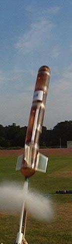
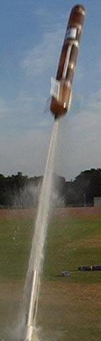
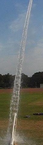
4 Section 1: What is a water rocket? At its simplest, a water rocket is basically an upside down fizzy drinks bottle, which has had a nose cone and some fins added. The nose cone The job of the nose cone is to make the rather snub-nosed end of the fizzy drinks bottle more aerodynamic. Also if you have payload on your rocket, or a parachute mechanism, this is probably where it will be placed. The fins Others might disagree, but I think the fins are the parts of a rocket that really give a rocket its character. Technically, the fins are important for ensuring that the rocket flies smoothly Once we have added the fins and the nose cone, we have something which looks like a rocket. But how do we make it go like a rocket? First we need to add some water, and some kind of release mechanism, that will keep the water in the bottle, until we choose to release it. The water will then leave the bottle through its nozzle. Typically the bottle will be between about one quarter and one third filled with water. Launch To launch the water rocket, we need to pump air into the rocket: this provides the energy for the launch. As the air enters, it bubbles up through the water and pressurises the empty space above the water. You can see that the release mechanism has to be really quite clever, allowing air into the rocket, while not allowing the water to escape until we activate a trigger. 1
, and without too much difficulty its possible for a rocket to reach heights in excess of 30 m.")
5 When the trigger activates the release mechanism, the pressurised air within the rocket pushes the water rapidly out through the nozzle, sending the rocket rapidly into the air. Peak launch velocities can easily reach 30 metres per seconds (about 60 miles per hour), and without too much difficulty its possible for a rocket to reach heights in excess of 30 m. But launching a rocket straight up in the air can be dangerous 2

6 There are two ways to make your water rocket launch safe. The first way is to use a parachute or other similar device to slow the descent of the rocket. Seeing a rocket launch, reach its peak, deploy a parachute and descend gracefully to Earth, is a really great sight. Unfortunately, its not a very common sight, because getting a parachute to open at just the right time is very tricky, and requires real ingenuity. The second way to safely launch your water rocket is to launch it an angle. Of course, this makes it safe for you, but potentially dangerous for passers by! One of the best features about launching at angle is that water rockets can travel really impressive distances. Reaching 30 or 40 metres should be quite achievable, but distances beyond 100 m are possible with some careful design. The main problem with launching the rocket at an angle is that the rocket can no longer stand on its own feet, and if it is supported entirely by its nozzle, then it tends to flop over. This happens before launch, and most importantly, it happens just after launch before the rocket has begun to move quickly. 3

7 There are two standard ways to solve this problem: launch ramp and launch tubes. Launch Ramps A launch ramp supports the weight of the rocket before launch and just after launch, until its speed has built up. Launch Tubes A launch tube is a tube that runs through the nozzle of the rocket. When the trigger activates the release mechanism, the rocket slides along the launch tube before fully attaining free flight. This has two advantages. The first and most obvious advantage is that the launch tube stops the rocket from flopping over just after launch. In this respect it acts like a kind of internal launch ramp. The second advantage is not quite so obvious. Once the trigger has been activated, the high pressure gas inside the rocket expands, and pushes (as the middle section of the figure below shows) the rocket along the launch tube. As it slides along the launch tube it accelerates, and it can be moving quite fast when it leaves the launch tube. However, while it is on the launch tube, it is not losing any water. This gives the rocket a kind of moving start and allows it to use its charge of water more effectively. This can significantly improve its performance. 4

8 Why? So now you know what a water rocket is. But perhaps the question still lingers: What s the point? The answer is very simple: building and launching rockets is just enormously enjoyable. It combines the simple pleasure of watching in awe at the power of a compressed gas, with the rather more subtle pleasure of mastering an engineering problem. In short, its fun for all ages. The challenge: Some teams, designs and launches from NPL s Water Rocket Challenge Photo Credits: Photos from the NPL Water Rocket Challenge Web Site. Thanks to Mike Parfitt, Steve Forrester, Clive Scoggins, Stuart Rogers 5


, an enormously strong plastic. A tennis ball, or rubber ball weighing about 60 g.")

9 Section 2: How to make a basic water rocket In Section 1, we saw what a water rocket was. In this section we ll see in detail how to make a basic water rocket that will fly pretty well in a wide range of conditions. We ll cover how to launch your rocket in Section A Basic Rocket What you will need A two-litre fizzy drinks bottle: this will form the main body of the rocket. Be sure only to use bottles that contained fizzy drinks: similar looking bottles which contained still drinks (cordial, milk drinks etc.) are not suitable. Fzzy drinks bottles are made from PET (short for Polyethylene Terephthalate), an enormously strong plastic. A tennis ball, or rubber ball weighing about 60 g. This will form the main part of the nose. Some corrugated cardboard, or better still, corrugated plastic. This will be used to make the fins. Duck tape or equivalent strong, sticky tape. Scissors or a knife. Time: Between 30 and 40 minutes When completed it will look like Schematic Actual First of all you start with a fizzy drinks bottle. You need to empty out the fizzy drink, get rid of the labels, and rinse it with water. Supermarkets sell value ranges of lemonade and fizzy water that cost only perhaps 20 pence per bottle so this shouldn t cost too much. Now you need to add a nose cone and some fins 6


 is waterproof, and")


.")

10 The nose cone The nose cone needs to be slightly pointed, and as we ll see in Section 4, it s also important to have a little bit of weight towards the front of the rocket. My favourite way of achieving both these aims is simply to tape a tennis ball to the end of the bottle. This might not look quite as aerodynamic as you were hoping for, but trust me, it will fly! The fins These fins were cut out of an old estate agent s For Sale board. More technically, this corrugated plastic (known as Corriflute ) is waterproof, and has excellent rigidity for its weight. If you can t find any old For Sale signs, a source of Corriflute is listed in Section 9. However, then there are many suitable alternatives. Corrugated cardboard will do, but does tend to go soggy after a few launches. Also many packaging materials have the same design requirements as water rocket fins (high rigidity-to-weight ratio). One common choice is to cut up old CD s to use as fins. If you do this please then make sure you put tape over any sharp edges in case your rocket should hit someone. I ve used three fins rather than four, because three fins means one less fin to cut out! I ve included a picture showing the actual dimensions I used on these fins, but this design is far from optimal. I like this design because the rocket can stand on the fins 7

11 (which is actually quite handy), and they make the rocket look a little bit like the rockets from Tintin books. The fins are simply taped to the side of the rocket. They need to be reasonably firmly attached in order to stop them being ripped off during the launch. The fins will almost certainly be damaged on landing, but then they will not be too difficult to repair. Whether you use this fin design or your own, the important things about the fins are that: All the fins should be the same as each other, They should be positioned towards the back of the rocket. They should arranged symmetrically around the rocket (every 120 if you have three fins or every 90 if you have four) They should be thin when viewed head on Decoration Decorating and naming your rocket can give a disproportionate amount of pleasure for the time it takes: I give you: The Flying Gherkin! Critique This rocket is not optimised in many ways, and in Section 4 we ll see how to optimise each part of the rocket, and discuss the different design compromises that you will need to make. But you can probably already see that it could be made lighter, the nose cone could be made more aerodynamic, and the fins could be reduced in size. However, the aerodynamics are not too bad, and the weight and fin size are such as to keep the rocket stable in flight. In short: it s not a bad starting point. Vital Statistics Internal Volume 2 litres Mass when empty 171 g (0.171 kg) Length 45 cm (0.45 m) Area of Fins 1200 cm 2 Frontal Cross Sectional area 62 cm 2 8


12 Section 3: Launchers Launchers are more complicated to build than rockets, and it will take you much longer to build a launcher than it will to build a rocket. For this reason I think you might like to consider investing in a commercial launcher. I tested the rocket described in the previous section using a launch system available from Maplin (Section 9). The Maplin system uses a special nozzle which screws onto the bottle in place of its cap. The nozzle is shaped to fit into normal garden hose fittings, and the system comes with a quick release based on normal garden hose connectors, and activated by a neat system based on a bicycle brake cable mechanism. Right: details of the special nozzles used by the Maplin Launcher Far Right: The nozzle screwed onto the rocket. Right: The rocket The Flying Gherkin installed on the Maplin Launcher ready for launch Far Right: Filling the rocket with a measured charge of water. Personally, I have used parts of the Maplin launcher mechanism, but attached them to my own launch ramp. It s not the best design in the world, but it is my design. And it may be that you too long to design and build your own launcher. In which case, the following pages may be of assistance. 9


13 Making your own launcher First of all, a confession: before I made the launcher shown on the previous page, I made a launcher similar to those featured below. However it didn t work very well. So these instructions are not based on what I have done, but rather on what I would have done if I had been clever enough to consult my colleagues before I started building. Launchers are more complicated than water rockets, and if you are attempting this, then you are probably quite good at DIY, and won t need complete instructions. So in this section I will only describe those parts that I think are not obvious. I will describe two designs, one without a launch tube (Design A) and one with a launch tube (Design B). If you attend any water rocket gathering, you will see that these designs are simply two stars in a galaxy of possible designs. When completed your launcher might look something like Below: Schematic of the main components of a launcher. Below Left : A typical rocket launcher without a launch tube: we ll call this Design A. 10 Below Right : A typical rocket launcher with a launch tube: we ll call this Design B.
, and is constructed out of standard 15 mm copper plumbing tube soldered together.")
. However, the design depends on small details of the fittings so you will need to check what will and won t work with the particular fittings you choose.")

 The bottle fits into a 28 mm to 28 mm straight through connector, attached to a 28 mm to 15 mm reducing adapter, which in turn is attached to 15 mm copper")

 the large diameter plumbing tube is pulled away. This allows the cable ties to move outwards permitting the rocket to launch.")
14 The launching Mechanism Connecting the rocket to the launcher and designing a launching mechanism is probably the trickiest part of the construction. Let s look at how the two designs approach this. Design A Design A is Jaco Stander's version of the Ian Clark s cable tie launcher (see Section 9 for a web link), and is constructed out of standard 15 mm copper plumbing tube soldered together. Soldering is probably quite hard for beginners, so as an alternative, the launcher could have been made using either compression fittings (which can be made pressure tight with spanners) or push fit fittings (which require no additional tools). However, the design depends on small details of the fittings so you will need to check what will and won t work with the particular fittings you choose. In this design, the screw thread on the outer part of the bottle is removed with sand paper to make a smooth surface. This can be done by hand, but a much better finish can be achieved by spinning the bottle and applying gentle pressure with sand paper. Before Sanding After Sanding The launcher and launching procedure is illustrated in the Figure below. The launching technique for Design A (a) The bottle fits into a 28 mm to 28 mm straight through connector, attached to a 28 mm to 15 mm reducing adapter, which in turn is attached to 15 mm copper pipe. (b) The modified bottle-end is fitted snugly into the 28 mm throat of the adapter. The pressurised seal is achieved by the use of a thin 28 mm diameter O ring. Notice that at this point all the pipework visible in the illustration will be filled with water. (c) The bottle is then locked in place by cable ties, which in turn are held in place by large diameter plastic plumbing tube. At this point the rocket can be pressurised, and will not launch until (d) the large diameter plumbing tube is pulled away. This allows the cable ties to move outwards permitting the rocket to launch. (a) (b) (c) (d) The major problem with Design A is that the rocket is only supported at the neck, and since a large rocket can weigh several kilograms when filled with water, this makes the rocket liable to sag before launch. This could be overcome by the addition of either a launch ramp to support the rocket, or a launch tube. A photograph of the launcher in action can be seen in the collection on Page 5 (one down from the top right), where Jaco has used an improvised launch ramp. 11


 The bottle with its modified cap slips over a piece of polished 22 mm plastic pipe.")
15 Design B Design B is by Dave Lowe, and uses a launch tube to add support and give extra momentum at launch. It is constructed out of two types of plumping pipe: standard 22 mm diameter plastic plumbing tube, and undersized 21.5 mm plastic overflow pipe. It is assembled using simple push-fit plumbing connections. In this design, a 22 mm diameter hole is drilled through a standard bottle cap. Be careful when drilling because any drilling operation could be hazardous! The plastic of the cap is soft, and we recommend the use of wood bit rather than a conventional high-speed steel drill. The cap can now be slipped over the 21.5 mm overflow pipe trapping an O ring between the bottle top and the tube. This should form a pressure-tight sliding seal against the wall of the tube. Standard 22 mm plumbing tube will not fit inside the neck of PET bottle. To make sure you get the correct type of pipe, take a bottle along to the shop to check the pipe will fit before you buy it! If the bottle is a tight fit on the tube, reduce its diameter slightly using sandpaper. One technique is to fit the tube into a drill and rotate it, and hold fine sand paper against the tube. You may need to add a small amount of lubricating oil or grease to allow the bottle to slide easily along the tube. The launching technique for Design B (a) The bottle with its modified cap slips over a piece of polished 22 mm plastic pipe. In this design, the pipework visible in the illustration extends far enough into the bottle to prevent water overflowing into the pipes. (b) The bottle is then locked in place by cable ties, which in turn (c) are held in place by large diameter plastic plumbing tube. At this point the rocket can be pressurised, and will not launch until (d) the large diameter plumbing tube is pulled away. This allows the cable ties to move outwards permitting the rocket to launch. (a) (b) (c) (d) 12


16 Designs A and B both use cable ties as a key component in the launching mechanism, but as the photographs below show, they adopt a what I can only describe as different design philosophies. Dave has gone for the minimum of three cable ties, and Jaco has gone for the maximum number of cable ties that can be arranged around the rim of the bottle. Which is better? I don t know: they both work very reliably! Photographs of Designs A and Design B Details of the launch mechanism of Design A. Below. The cable ties loosely arranged around the 28 mm to 15 mm plumbing adapter. Right. The large diameter plumbing tube has been lifted up to clamp the cable ties over the neck of the rocket. Details of the launch mechanism of Design B. Right. The arrangement of the bottle, the sealing O ring and the modified cap used to clamp the O ring against the launch tube. Far Right. The three cable ties held loosely arranged around the neck of a bottle. The large diameter plumbing tube has not been lifted up completely to clamp the cable ties over the neck of the rocket. Notice that launch tube continues inside the water rocket 2. Pressurised connections & the pumping valve Both designs A and B use pipework systems that are readily available from plumber s merchants and DIY stores. However one part of a rocket launcher which is not available from shops is a component to allow connection between these pipework systems and a bicycle pump. Both designs tackle this by installing either a bicycle tyre valve or a car tyre valve. The Figure over the page shows details of Design A s connector. 13
 a standard 15 mm compression fitting (called a union ); a car tyre valve; the compression nut. Right. The valve shown assembled.")


17 Details of the pumping valve in Design A. Left. The valve is shown disassembled, showing (from left to right) a standard 15 mm compression fitting (called a union ); a car tyre valve; the compression nut. Right. The valve shown assembled. A similar arrangement can be made with 22 mm plumbing fittings, but there it will be necessary to drill a hole in an end-cap, and to fit the car tyre valve in place. Glue or sealant should not be necessary, because the tyre valve fitting is designed so that as the pressure increases, the seal will improve. A similar design can also be made using bicycle tyre valves Pump types One last feature of launcher design concerns the choice of pump used to pressurise the water rocket. There are broadly three types of pumps available: Hand pumps, foot pumps, and stirrup pumps. Any of these can be used, but the must have feature for any pump you choose is a pressure gauge: if the pump doesn t have a pressure gauge then you will have no idea how your rocket will perform and be unable get it to behave reproducibly. Having said that any type of pump can be used, I would definitely not recommend a normal bicycle hand pump. The amazing performance of water rockets comes from energy stored in the compressed air, and the source of the work required to compress the air is your arms and legs. Aside, from normally lacking a pressure gauge, handpowered pumps are very hard work. Stirrup pumps (which allow the work to be shared across both arms), and foot pumps (especially dual-piston pumps) are both popular, but amongst the people who do a lot of rocketeering, the stirrup pump seems to be the preferred choice. 14
18 Section 4: Optimising Rocket Design Aside from actually firing the rockets, designing the rocket itself is the part of rocketeering I enjoy most. In this section we ll look at some of the factors that you will need to consider if you want to optimise the design of your rocket. Design considerations Size (Volume) The first consideration is the size of the rocket you want to construct. Looking around the shops, you will see a wide range of fizzy drinks bottles available, and any of them can be modified to make a water rocket. It s common to find 500 ml, 1 litre, 2 litre and even 3 litre bottles. Larger bottles tend make more spectacular launches, but if you want to go larger than three litres then you will need to construct a rocket by joining together more than one bottle. There s some tips on how to make multi-bottle rockets later on in this section The volume of the rocket determines the maximum amount of energy that can be stored in the compressed gas. The energy is proportional to both the pressure and the volume. There are limits to the pressure that the rocket can sustain (5 atmospheres [or 75 psi] appears to be a safe working limit) and so in order to increase the total amount of energy available, it is necessary to use a larger rocket. With a little ingenuity it is possible to increase the volume with relatively little cost in terms of added weight. Weight The lower the weight of your water rocket, the better it will fly. Most of the work of designing a lightweight rigid structure has been done for you already by the manufacturers of the fantastically strong PET bottles. In order to capitalise on the strength-to-weight ratio of the bottles, you need to avoid adding too much weight as you improve the aerodynamics of the bottle. It is also important to add the weight in the correct places so that your rocket is aerodynamically stable. The distribution of weight along the length of the rocket is one of the factors which determines whether it will fly like rocket, or like a bottle. What s the difference? An aerodynamically stable rocket flies with its nose first, and should have a flight trajectory like a beautiful smooth arc. Right: An aerodynamically stable rocket trajectory. Notice that air-resistance tends to make the trajectory asymmetric, with the rocket falling rather more steeply than it ascends. An aerodynamically unstable rocket may start out with its nose first, but its flight will quickly become unstable and it will flap and tumble in the air, and then simply fall to Earth. 15


19 Right: An aerodynamically un-stable bottle trajectory. Several commercially sold rocket systems have rockets that perform in this way. In order to make your rocket fly like a rocket rather than like a bottle, the weight needs to be in the front half of the rocket. However depending on the design of your fins, this may or may not be enough to ensure aerodynamically stable flight. One of the most important properties of your rocket is the position of its centre of mass, sometimes called its centre of gravity. Estimating the position of the Centre of Mass Since your rocket will spend most of its flight without any water in it, this makes it easy to find its the centre of mass by simply tying a string around the rocket and moving the suspension point along the rocket until you find the balance point. The further forward this balance point, the more likely it is that your rocket will be stable in flight. Below: Finding the centre of mass of a rocket by suspending it from a thread. Fins The fins on a rocket provide a mechanism by which aerodynamically stable flight can be ensured. To understand the role of the fins, it is necessary to consider the forces on a rocket when it becomes slightly misaligned in flight. If these forces act to increase the degree of misalignment, then the rocket will not fly well. If these forces act to decrease the degree of misalignment, then the rocket will fly like a rocket! We ll see how the fins help to achieve stability in the next section. Aerodynamic stability To understand aerodynamic stability we need to consider the forces which act on the rocket both when it is flying correctly, and also when it is misaligned. Let s consider two different rockets (let s call them Rocket A and Rocket B) which are the same shape and have the same fins, but which have different weight distributions and so have their centres of mass positioned at different places. In particular let s assume that Rocket B has its centre of mass much further back than in Rocket A. 16


20 Rocket A Rocket B Now let s think about the forces when the rocket is travelling in the direction of the blue arrow. The main drag forces act on all the surfaces exposed to air moving past the rocket. For a typical rocket oriented correctly, these forces act mainly on the nose cone, because the fins are usually very thin and expose very little cross section to the air through which they move. Now consider what would happen if the rocket became slightly misaligned. In this case much more of the rocket would be exposed, and the drag forces would increase significantly. The forces would act: on the nose of the rocket, along the exposed side of the rocket, and on the fins. The forces along each portion of the rocket are difficult to calculate or measure precisely, but there will be some point on the rocket which is their effective point of action. This point is known as the centre of pressure, and is marked with a purple dot in the figures right and left. Because the shapes of the two rockets are the same, the centre of pressure lies in the same place. But because the centre of mass occurs in different places on each rocket, the effect of the same drag forces on each rocket is quite different. 17

 the centre of mass lies further backwards along the rocket axis than the centre of pressure.")
 or unstable (like Rocket B).")

21 For Rocket A (left) the centre of mass lies further forwards along the rocket axis than the centre of pressure. The extra drag forces therefore act more on the back end of the rocket and tend to push it back into line. Technically we say the drag forces exert a torque which acts about the centre of mass to restore optimal flight attitude. For Rocket B (right) the centre of mass lies further backwards along the rocket axis than the centre of pressure. The extra drag forces therefore act more on the front end of the rocket and tend to push it even further out of line. So it is the relative positions of the centre of mass and the centre of pressure that determines whether a rocket is aerodynamically stable (like Rocket A) or unstable (like Rocket B). We saw in a previous section how to determine the position of the centre of mass, but how do we determine the position of the centre of pressure? Estimating the position of the Centre of Pressure Estimating the position of the centre of pressure turns out to be rather hard to do accurately, but there is a simple technique which you can use to make a rough estimate of its position. This involves making a flat silhouette of your rocket. To understand why this is relevant look at the photographs below which show what the rocket would like if it became misaligned in flight. Left: A photograph of the Flying Gherkin from directly above its nose cone: this is what you would see if the rocket were flying directly towards you. Right: Exposed surfaces of the rocket: The circle shows the area of the rocket exposed to the oncoming air. The fins are rather thin and move easily through the air. Left: This picture shows the Flying Gherkin slightly misaligned: this is what you would see if the rocket were flying directly towards you, but its back end had swung around slightly. Right: In this attitude, additional surfaces (outlined and shaded) are exposed to the oncoming air. Some of these surfaces are on the side of the rocket and some are on the fins. 18

 of the rocket, and then estimating the centre of mass of the cut-out.")
of the rocket. Right. Assessing the centre of mass of the rocket and its silhouette together.")


22 The silhouette technique considers what would happen if for some reason your rocket were flying through the air sideways. This is obviously a more extreme scenario than the misalignments considered above, but let s follow the logic through. If this were happening then the surfaces of the rocket exposed to oncoming air would not form a circle (as when the rocket is correctly oriented) but rather would look like a silhouette of the entire rocket. The position of the centre of pressure of the rocket can be estimated making a silhouette (or cut out) of the rocket, and then estimating the centre of mass of the cut-out. Illustration of the silhouette technique for estimating the centre of pressure. Above Left: Drawing around the rocket. Above Right: Silhouette (cut out)of the rocket. Right. Assessing the centre of mass of the rocket and its silhouette together. We estimate the centre of pressure of the rocket to be in roughly the same relative position as the centre of mass of the silhouette. Notice that the rocket design with its large light, fins projecting back from the body of the rocket help to keep the centre of pressure towards the rear of the rocket. Also, extra weight in the nose of the rocket (a tennis ball) helps to keep centre of mass towards the front of the rocket. As the photograph above shows, the centre of mass of the silhouette is much further back along the rocket body than the centre of mass of the rocket itself. To the extent that the centre of mass of the silhouette really is a good estimator for the centre of pressure of the rocket, we can see immediately that The Flying Gherkin is aerodynamically stable. If the Flying Gherkin were flying sideways, then the air pressure would cause an effective force to act at the centre of pressure. Since the centre of pressure lies further back along the rocket than the centre of mass, the air pressure causes the rear of the rocket to be pushed backwards, and the nose of the rocket to swing forward, restoring the correct flight attitude. Tip: If your rocket is bigger than a sheet or two of A4 paper, then rather than drawing around your rocket, you may find it easier to make a scale drawing of your rocket. Drag As the water leaves the rocket s nozzle, it pushes the rocket forward. But this acceleration is decreased because the rocket needs to push air out of the way. The force required to push air out of the way is known as aerodynamic drag, and without specialist facilities, it is rather difficult to measure. 19

23 Travelling at just a few metres per second we are hardly aware of drag, but at higher speeds, drag dominates the motion of projectiles. For the rocket-shaped projectiles we are interested in, drag forces become significant above approximately 10 metres per second. Just after launch, a water rocket might reach a maximum speed of 20 metres per second, and a high-pressure rocket might reach 40 metres per second. At speeds such as this it is essential to create a design with low drag. Assuming your design is basically rocket shaped (pointy-nose, long body, fins) then you can minimise the drag by considering the following points. Nose: This nose needs to be : Cone shaped, but there is no need to make it excessively pointy. In fact, from a safety point of view this is really quite undesirable. Weight may need to be placed in the nose. I am fond of using tape around a tennis ball, but other designs use plasticine stuffed into a cardboard or plastic nose cone. Body: The body needs to be: As smooth as possible. For a given rocket volume, long thin rockets tend to have lower drag than short fat rockets. Fins: The fins need to be: Thin and light Arranged symmetrically around the body of the rocket: usually there are three or four of them. Positioned as far back along the rocket as possible Fairings A fairing is defined in my online dictionary as: fair ing1 n a streamlined structure added to an aircraft, car, or other vehicle to reduce drag. See also cowling Fairings are used in two quite different ways. The first technique is used when joining two bottles together: a midsection of a bottle is cut out and placed around the joint for strength and streamlining (see Figure on page 22). The second technique (see right) adds whole bottles or parts of bottles onto the water rocket engine to produce a longer rocket. This is a useful way of moving the centre of mass forward along the rocket to improve stability. Nozzle The nozzle is the transducer which converts the energy of the expanding air into linear momentum of the water exiting the back of the rocket. The efficiency of the nozzle measures the extent to which energy is wasted in this process. Losses can occur due to friction, viscosity, and off-axis acceleration of the water. You have rather little control over the first two of these properties, but your design can affect the third process. 20


 which will mechanically join the bottles, and then to seal the component in place.")
24 Consider the two bottles shown left and right: the left-hand figure represents the standard fizzy drinks bottle, and gives acceptable nozzle performance. However, the style of bottle shown right offers improved nozzle performance. Its gently sloping shoulders guide water in just the right direction and little energy is wasted in pushing the water sideways towards the nozzle. Unfortunately this style seems to be only available in one litre sizes. One further parameter may be used to describe a nozzle: its flow impedance. This is mainly determined by the minimum cross-sectional area: the larger the area, the lower the impedance, and the quicker water comes out; the smaller the area, the higher the impedance, and the slower water comes out. In the limiting case of a very high impedance, water will simply trickle out the bottle, and it will not leave the ground. Multibottle rockets Joining two or more bottles together to make a pressure-tight joint is simple in principle, but tricky in practice. The basic technique is to find a component (typically a plumbing connector or valve) which will mechanically join the bottles, and then to seal the component in place. Let s look at a couple of similar techniques. In the first technique one begins by drilling a hole in the centre of the bottom of a bottle. The hole should be around 12.5 mm in diameter (a half-inch drill will be fine). A wood drill will generally give a better result than a standard high-speed steel drill. Now one inserts a car tyre valve into the bottom of the bottle. This is the same kind of valve that Jaco and Dave used to make their pumping valve and is illustrated on Page 14 Before inserting the valve into the bottle, the insides of the valve need to be removed with needle-nosed pliers or similar. This should result in a straight hole through the centre of valve with a diameter of roughly 3 mm. Now we need to attach another bottle to this valve. To do this we begin with a standard bottle cap and drill a hole which will allow the stem of the tyre valve to protrude as shown below. We now have to make the connection pressure tight. To do this one first places a rubber washer over the valve stem, and squeezes it tightly into place with a nut made from a cut down cap for a tyre valve. One then seals the entire connection with silicone sealant and allows the assembly to set for 24 hours. 21


. Joining bottles together. Left: Bottle cap attached to the bottom of a bottle.")
25 The arrangement now looks like the leftmost figure in the set right. One can now screw a second bottle into the first bottle to make a pressure tight seal. The resulting joint should be pressure tight, but it is not very aerodynamic, and will also be rather fragile and flexible. The last step is to add a fairing to reduce drag. One clever way to do this is to cut out the central part of yet another bottle and slip it over the combined bottles. To do this you will find it convenient to slightly reduce the pressure in the combined bottles by sucking on them. The combined bottles will crumple a little, but this does not seem to affect their strength as long as the plastic is not creased. When reinflated, the fairing will be held firmly in place. This process can then be repeated to make rockets as large as you have the patience to create. Please note, however, that since the energy stored in a large rocket can be considerable when pressurised, you should be sure to observe the pressure safety precautions (Section 8). Joining bottles together. Left: Bottle cap attached to the bottom of a bottle. Centre: Two bottles joined together (the fairing is not yet in place) Far Right: There are many other ways of joining bottles together using cable entry grommets or similar. Small hands are an advantage for this fiddly work. Alternative technique: Using similar principles to those described above, a cable entry grommet for electrical wiring (above right) can be used to make a large aperture bottle connector. 22
26 Parachutes I am not in a position to tell you how to get a parachute to deploy correctly, because I have never managed to do it myself! Also, when I ve asked people who have done it what the secret is, they have been somewhat secretive! But I can tell you why it is so difficult, and I can pass on one or two hints given by some of the less secretive rocketeers. Generally its considered that the ideal time for deployment is when the rocket reaches its maximum height (apogee). The problem is to tell when this occurs. The Figure (right) shows the calculated speed of a standard rocket as a function of time. From this graph it is possible to see why detecting the apogee is a problem. After the acceleration phase, both the horizontal and vertical components of the rocket velocity gently decrease. At the apogee, there is no change in the forces acting on the rocket, and so it is hard to detect. Velocity (m/s) Water expelled 'Gas Blast' ends When the vertical velocity component is zero the rocket is at its maximum height Time (s) Horizontal velocity Vertical velocity In order to arrange for the parachute to deploy correctly, I have seen only two generic types of mechanism. The first detects the height of the rocket, and the second activates at a pre-determined time. Another possibility would be to have a mechanism based on the orientation of the rocket, but I have never seen this implemented. The first height-detecting mechanism I have seen consisted of a piece of thread attached to the ground: it broke during the rapid acceleration phase. The second height-detecting mechanism consisted of a rocketeer with a radio-control. The parachute was stowed in the nose of the rocket beneath a cover which was held in place by nylon fishing line. The radio control activated a heater that melted the fishing line, causing elastic bands to pull off the cover, allowing the parachute to deploy. This ingenious mechanism worked perfectly. Most of the time. This type of deployment mechanism could also be used with a timer. The mechanisms based on timing involved a tiny clockwork timer (See Section 9) which could be set to activate after periods of just a few seconds or so. Arranging for the timer to be started on launch, and then deploy correctly proved very tricky. When the mechanism worked, it worked perfectly, but frequently it deployed the parachute on launch, or failed to deploy it all. 23
27 Section 5: Testing your Rocket The way you test your rocket is what distinguishes those who want to just have bit of fun (which is great in itself) and those who want to understand and improve their design (which the first step on the road to being a successful engineer). At the heart of this test process is measurement. You need to: measure the properties of rocket before launch, and then measure the performance of rocket. You then need to use your understanding of the launch process and flight dynamics to try to work out which launch properties most significantly affect the performance of the rocket. Rocket Properties Weight of Empty Rocket: This is (pretty obviously) the weight of the rocket without the water in it. This will be the part of the rocket which makes the whole journey. Using electronic kitchen scales it is not too difficult to measure to the nearest gramme, which is more than accurate enough for our purposes. Total Volume: If you have just a single bottle design, the total volume is likely to be very close to the volume stated on the label. If you have constructed a multi-bottle rocket, then you probably need to measure this. The easiest way is to weigh the rocket empty (see above) and then weigh it full of water. Each gramme of excess weight corresponds to 1 cubic centimetre of water. Or each kilogramme corresponds to 1 litre of water. Water Volume: This is something you can easily customise and which makes a big difference to the performance. A good starting point is generally to fill with about one quarter water. The optimum filling depends on a number of factors, but is generally in the range from 20% to 30%. One thing you can do before you leave home, is to mark the side of the rocket with tape to show where (say) the 20% or 25% mark is: remember you will generally be filling the rocket when it is upside down so this mark will generally be in a non-obvious position. Launch Angle: If the rocket were an un-powered projectile with no aerodynamic drag, then the angle to give the greatest range would be 45. However, this is not the case for a water rocket, although the optimum angle is unlikely to be very far from 45. My feeling is that launching slightly more vertically than this gives the best range, but you should check this for your rocket. Launch Pressure: Increasing the pressure increases the stored energy at launch, which increases the maximum speed attained by the rocket, and this increases the launch range, flight time, and maximum height. However, you will find that increasing the launch pressure by a given amount (a) becomes harder to do and (b) makes less and less difference. The reason is aerodynamic drag which increase very rapidly with increasing launch speed, and steals all the kinetic energy imparted to the rocket. If you have a launch pressure of 5 atmospheres (75 psi) and are still looking for improvements, then its better to try reducing drag rather than increasing the pressure further. Other features: You need to note how you have set the fins, or whether you are trying any other interesting alterations either to the rocket or to the launcher. Rocket Performance Ground Range: This is the distance between the launch point and the point where the rocket hits the ground. When you begin rocketeering, increasing the range is simplest 24
28 and most obvious measure of success, but as you get better, you will find that increasing the range is not so obviously a good thing. The first problem is that once the range becomes long (beyond 100 m or so) it takes a long time to measure the range and retrieve your rocket. Secondly, depending on the kind of space you have available to launch into, it becomes increasingly difficult to ensure that your rocket will not hit a passer by, or leave the field or park where you are practicing. At the extremes of the range over 200 m it simply becomes impossible to find anywhere to safely launch! The best way to measure the range is probably with a wheel-based odometer. However, for most practical purposes, counting an adult s purposeful strides to the landing point will suffice for comparative measurement. If you want to go one step better than this (no pun intended), the adult can calibrate their stride by walking 10 purposeful paces, and measuring the distance travelled. From this you can work out the actual length of each stride in metres. Height: This is a really interesting property of the rocket s trajectory, but unfortunately one that is very hard to measure. If you really want to know how high the rocket goes, then I would recommend a straight up launch (see Page 3 for warning!) with a long length of sewing thread attached to the tail of the rocket. The thread should be laid out on the ground, so that as the rocket increases in altitude it can lift the thread off the ground. If you want to measure the height for a non-vertical launch, then (aside from complicated triangulation from analysis of multiple video films) the only way I know of is to use an altitude data logger available from model aircraft shops (See Section 9). Time in the air: The length of time spent in the air is a good measure of rocket performance, and is probably best measured with a sports stopwatch. With a little practice you should be able to measure this to the nearest tenth of a second or so. If your rocket has no parachute, then your flight times are likely to be under 10 seconds, but if you use a parachute, then flight times could be longer than a minute. Launch Velocity: One very useful addition to your measurement armoury is the advent of affordable digital cameras which will take video clips. Typically the cameras can record at either 10 or 15 frames per second. By analysing video footage frame by frame it is possible to make estimates of previously un-measurable properties such as launch velocity. These measurements can be considerably improved by placing a metre rule or other object of known size in the field of view close to the rocket trajectory. It will also help to place the camera on a tripod so that there is no shake at the moment of launch. To analyse a movie frame by frame, the files produced by the movie can be viewed with the Quicktime video player downloadable from the web (Section 9). The figure overleaf shows five frames extracted from a movie (.avi format) from a typical digital still camera operating in movie mode. 25
 in 1/15 th of a second, which corresponds to a speed of approximately 6 metres per second. Between the third and fourth frame, the rocket travels approximately 3 bottle lengths (roughly 1.")


29 t = 0 t = s t = s t = s t = s Between the second and third frame, the rocket travels approximately 1 bottle length (roughly 0.4 metres) in 1/15 th of a second, which corresponds to a speed of approximately 6 metres per second. Between the third and fourth frame, the rocket travels approximately 3 bottle lengths (roughly 1.2 metres) in 1/15 th of a second, which corresponds to a speed of approximately 18 metres per second (40 miles per hour). The increase in speed from 6 metres per second to 18 metres per second takes only 1/15 th of a second, which corresponds to an acceleration of = 180 metres per second per second. Colloquially, this is around 18g, where g is the acceleration due to gravity at the Earth s surface. Aside from quantitative results, viewing the movies is also instructive in showing how the water leaves the rocket. In this case it is clear that the water really does move mainly backwards along the axis of the rocket indicating a satisfactory nozzle design. Testing Before you begin testing, please read Section 8 on Safety. Water rockets are on the whole pretty safe, but the potential exists for a nasty accident that will take all the pleasure out of the endeavour. So for your own sake, and others, follow the safety guidelines. Tips Bring enough water: a barrel used for brewing beer is helpful, having a tap at the bottom. Plastic hose, funnels, and measuring cylinders are all likely to come in handy. Try to get into the habit of recording what you do as you do it. Its amazing how the process of simply writing down what I tried: what happened can help to clarify what may seem confusing results. Enter results on a laptop, or use a sheet such as the one on Page
30 Try to use the computer model (Section 7) to estimate some of the relevant parameters, and to predict what you think will happen. Don t worry too much about precise measurements. Estimating most quantities to within 5% to 10% is generally sufficient to gain a good understanding. Ideas for experiments to try Try doing the same thing three times. This will allow you to assess the reproducibility of your rocket s performance. If you can t get your rocket to do roughly the same thing when you launch it in the same circumstances, then you are not going to be able really optimise its performance in any meaningful way. Try launching with no water: This is a nice demonstration of the principle of rocket propulsion. The rocket will still fly, but if you then add even a small amount of water (perhaps just 5% filling of the rocket), you should see a dramatic effect on the rocket s performance. Launch in teams of at least two. Its good to talk about what s happening as you launch and to explain your ideas, and one person can act as Safety Marshal or timer as the other launches. Try changing the launch angle and recording the range. You should find a range of angles (probably close to 45 ) where the range is insensitive to the precise launch angle. The graph right shows typical results from the water rocket simulator. It shows that changing the launch angle by ±5 around 45, makes very little difference to the range. This makes this angle setting good for testing the dependence of range on other rocket parameters, such as launch pressure. Range (metres) Range of angles with the same range Launch Angle (degrees) Try changing the launch pressure and recording the range. You should find that increasing the launch pressure always increases the range, but by smaller and smaller amounts. The graph right shows typical results from the water rocket simulator. It shows that at high pressures, reducing the drag factor of the rocket has an increasing benefit rather than simply using the brute force higher pressure approach. Increased range (m) Increased range from reducing drag by 10% Increased range from increasing launch pressure by 1 bar Launch Pressure (bar) 27
31 Water Rocket Test Sheet Date Time Rocket Identifier Launch Parameters Launch Number Rocket Mass Rocket Volume Filling Factor Launch Mass Launch Angle Launch Pressure Launch Results Range Time Height Video file identifier Other Other Notes 28


32 Section 6: Physics of a water rocket This section is for people who want to understand in general terms what happens during a rocket launch. The left hand column has the time before or after launch in seconds; the middle column shows what s happening ; and the right hand column contains my commentary. We assume a vertical launch of a two-litre rocket weighing 100 grammes when empty, and quarter filled with water at launch. The speeds and heights quoted are those derived from the water rocket simulator software described in Section 7. Further details of the calculations can be found in Section 10. Time What s happening? Comments 60 s The rocket is filled, and then placed on its stand. Everyone nearby is warned that the rocket is about to be pressurised, and then pumping commences. As the air is compressed it gets hot, and you should be able to feel this near the exit of the pump. However, as the air bubbles through the water it cools down again, so the air in your water rocket should be close to the temperature of the water 30 s Your chosen launch pressure is reached. To be specific, we ll assume that the gauge on the foot pump you have used reads 3 atmospheres. Since the pressure before you started was one atmosphere the actual pressure of the air in the bottle is now 4 atmospheres. 1 atmosphere sometimes called 1 bar, is roughly equivalent to: 15 pounds per square inch (psi) 2 kilograms per square centimetre pascal (Pa) The pressurised gas is the energy source for the rocket. A good rocket design will convert the maximum amount of stored energy into kinetic energy of the rocket. 5 s The final launch warning is given and if everything is safe, the launch mechanism is released. Just before launch the force on the nozzle is very large. At this point the 500 ml of water weighing 500 g (0.5 kg) makes up most of the mass of the rocket. 29

33 Time What s happening? Comments s As the catch is released, the gas pushes the water out through the nozzle, and the rocket begins to lift off. The pressure of the air begins to fall, and also its temperature drops as the air expands. After 10 milliseconds the speed is still quite slow (around 1 metre per second) because the rocket still has a heavy load of water on board. The rocket has moved less than a centimetre s Just under half the water has now left the rocket. The rocket has reached a height of around 0.5 metres and is travelling upwards at approximately 10 metres per second. This corresponds to very large acceleration of around 100 metres per second per second, or roughly 10g. If the nozzle causes water to be sprayed sideways, then this adds nothing to the lift forces. Frame by frame analysis of a video (Page 26) should show a tube of water trailing behind the accelerating rocket s Amazingly all the water has now left the rocket. If you could just imagine emptying 500 ml of water out of a bottle it might easily take 10 seconds. It has now all gone in just under a quarter of a second! The rocket is now travelling at around 26 metres per second. The pressure has fallen to 2.4 bar from its initial value of 4 bar. As the air has expanded it cools and is now at approximately 19 C. But it is still pressurised. However now that the exit is not blocked by water, the air finds it considerably easier to leave the rocket than the water did. 30
34 Time What s happening? Comments s After another 30 milliseconds, the pressurised air has left the rocket giving the rocket a last boost. This boost can have quite a considerable effect because the rocket is now much lighter than it was on launch. At the end of this phase, the rocket is moving at its maximum speed of around 35 metres per second. The rocket now enters the cruise or ballistic phase of its flight s to s In this phase of its flight, the only forces acting on the rocket are gravity, and the aerodynamic drag force. Gravity always acts vertically downward on the rocket, and limits the maximum height to around 34 metres. The rocket then falls, striking the ground after around 5.4 seconds at a speed of approximately 20 metres per second If the rocket is well designed, the aerodynamic drag always acts to oppose the direction of motion, so the drag acts downwards as the rocket ascends, and upwards, as the rocket descends. If the rocket is not so well designed, the aerodynamic forces can act on the rocket in other directions and cause it to tumble. If your rocket does this, look at the Section 4 on aerodynamic stability. 31

35 Section 7: Computer Simulation Water rocket simulation software has been written to operate under the Windows operating system. The software can be downloaded from the NPL water rocket site at: Disclaimer. This software has not been developed under NPL quality procedures and is not warranted for any use whatsoever. Got that? I can t be clearer. The software comes with no guarantee that it will do anything at all. That said, we believe that it is pretty Good for Nothing TM Introduction First of all you need to install the software using the standard Windows installer. When you launch the software and you will be faced with a screen similar to the following. First of all You probably feel tempted to click the big red Launch button. Well go ahead! The application will switch screens to show you the calculated trajectory of the rocket with the design parameters on the left-hand side of the window above. The key predictions for the flight duration, maximum height and range can be seen in the lower left of the screen. The basic idea of the program is that you: design a virtual rocket by choosing values for some key parameters; launch your virtual rocket by clicking the launch button look at the results and revise your design. 32


36 This cycle of design/experiment/measurement of results/re-design is the fundamental process of engineering. The purpose of the software is to speed up the design cycle, allowing you to focus your real design efforts on those parameters likely to have the most effect on your real rocket. Rocket Design Tab The left-hand side of the screen features the parameters that you can control. They are all inside a Rocket Design control box. Holding the cursor over a text box will bring up a short help message. Most of the parameters are easy to estimate, but some are not so easy. In particular, the Nozzle Impedance and the Drag Factor can be problematic. The nozzle impedance is a number which characterises how many cubic centimetres of water leave the nozzle per second per pascal of pressure difference between the inside and outside of the rocket. Using typical figures, a pressure of 1 atmosphere ( Pa) causes 100 cubic centimetres of water to leave the rocket in about 0.1 seconds, a flow rate of 1000 cubic centimetres per second. So this corresponds to an impedance of /1000 = 100 Pa s/cc. Increasing the nozzle impedance reduces the flow of water for a given pressure difference. 33


37 The drag factor is a number which characterises the magnitude of the drag force on the rocket. On this scale, a tennis ball has a value of 10, and a football has value close to 100. Most rockets will lie in the range between 10 and 100. If you take special care you can achieve lower values, and you will see that if everything else is optimally designed, it is the drag factor which will ultimately limit the performance of the rocket When you click either the launch button or the check parameters button the application will calculate some basic parameters that describe the launch, such as the amount of energy stored in the compressed gas at launch The gas blast refers to the phase of the rocket flight after the water has been ejected during which (the rocket being rather light) can undergo extreme accelerations. The energy per unit mass field shows the value of the initial energy stored in the gas at launch divided by the launch mass. The optimise button in the rocket design panel, evaluates the energy per unit mass for all values of filling factor from 1% to 99% and fills in the value which maximises the energy per unit mass at launch If you have a rocket design you like, you can save the key parameters in a text file (.txt), by clicking the appropriate SAVE button. Saved Rockets can similarly be reloaded for further study by using the LOAD button. Trajectory After the LAUNCH button is clicked, the application switches to the trajectory tab. The trajectory of the most recent launch is shown colour coded: The portion of the trajectory during which water is being ejected is shown in red The gas blast phase of the trajectory during which air is being ejected is shown in green The ballistic portion of the trajectory during which the rocket is in free unpropelled flight is shown in purple The ten previous launches are shown as blue lines. If you want to always see only on the last calculated trajectory, then check the Only plot the last rocket I launched check box. 34

38 If the screen becomes too cluttered then clicking the Erase Launch History will clear the screen. The maximum values of the range and altitude are preset at values likely to be appropriate. You can change them as you see fit, but you will need to click the launch button again to see the effect. The calculated trajectory can be saved as a tab delimited data file by clicking the SAVE button in the Trajectory panel. This file can be opened in many applications including MS Excel for further analysis. Alternatively, clicking the COPY button places a copy of the data on the clipboard which can then be simply pasted into an open Excel spreadsheet. Velocity versus Time Graph The velocity vs. time tab shows a graph of three quantities as a function of time Vertical velocity (blue) is the speed in the vertical direction. This curve rises, reaches a peak and then declines, falls through zero and reaches negative values, which corresponds to travelling downwards. The point at which the vertical velocity reaches zero is apogee, or the point of maximum altitude Horizontal velocity (red) is the speed in the horizontal direction. This curve rises, reaches a peak and then declines gradually, but in general it does not reach zero Air speed is the raw speed of the rocket. It is calculated as: Air speed = ( Vertical velocity) 2 + ( Horizontal velocity) 2 Notice that when the rocket is at apogee, the air speed is equal to the horizontal velocity. Also marked as vertical lines on the graph are: the time at which the water runs out; the time at which the internal pressure is equal to atmospheric pressure; the passage of each tenth of a second. 35

39 The scale of the graph is pre-set to match most flights with a maximum speed of 40 m s -1 and a flight time of 5 seconds. If you should find that the curves leave the graph, then you can reset the maximum values of the graph with your own values. After re-scaling, you will need to re-launch your rocket in order to see the curves. Commentary The last tab panel summarises the story of your last launch. Clicking the [Copy Commentary] button places this text on the clipboard so that it can be pasted into a word processor. Bugs reports, comments, and suggestions for improvements There are several known bugs in the water rocket simulator. The effect of these bugs is to introduce inaccuracies in the results of some of the rocket calculations in certain regimes. If you find any bugs that you think I might not know about, please let me know by at: michael.depodesta@npl.co.uk Disclaimer. This software has not been developed under NPL quality procedures and is not warranted for any use whatsoever. Got that? I can t be clearer. The software comes with no guarantee that it will do anything at all. That said, we believe that it is pretty Good for Nothing TM. 36

40 Section 8: Safety Building and launching water rockets is a pretty safe pastime, and I say that as someone who has had a water rocket land on their head more than once. But there are some hazards associated with both the launching of water rockets, and their construction and you should be aware of them. Taking some simple precautions should keep things safe Sharp knives and blades: any sharp knife or blade presents a potential accident waiting to happen, especially with children present. So when using craft knives or blades: Always cut away from your fingers When not using the blade, always cover the sharp surface with either the manufactures cover, or failing that a cork, or piece of soft wood. Rocket design: Do not use any sharp points on either the nose cone or the fins and never use metal fixtures or fittings external to the rocket body. Pressurised objects and pipes: during launching and testing, pipework and connections will be pressurised, and large forces can be exerted on different parts of your system. Outright failure of component is extremely rare (see below for pressure limits) but it is common for connections to creep while under pressure and then to pop out suddenly. When your launch system is pressurised, it should be treated like an unexploded firework. In particular you should keep small children away. We recommend that safety spectacles and ear plugs or ear defenders be worn while the launcher is pressurised. Pressure limits: at times the desire may come upon you to increase the pressure just a little bit more. If you feel tempted, please note the following. Use only PET bottles designed for fizzy drinks or carbonated water. Do not use PET bottles used (for example) for fruit cordial or milk drinks. These are not safe. Aside from leaking connections, the most likely component to fail under pressure is the water rocket itself. The precise pressure at which bottles will explode depends on the bottle design, its history, as well as any of the strange things you may have done to it. Collectively, the rocketeers at NPL feel that if you are using relatively new undamaged bottles, then keeping the pressure below 5 bar (75 psi or 5 kg per square centimetre) will pretty much avoid the risk of explosion. If you feel the temptation to increase the pressure above this, then I recommend you re-design your rocket with less drag: this will have the same effect without any additional risk (See page 27 for a graph). Launch procedure: when launching the rocket you should avoid any possibility that the rocket will hit any living thing. Since the rocket could land up to 100 metres away, this represents something of a challenge in any public access space! Please pick your spot carefully: most public parks are not suitable for any but the shortest flights. Launch in a team, with one person s job being to ensure safety. They should look out for people wandering into the firing range. Begin by firing at low pressures until you become familiar with your launch system. Remember that an accidental launch of the rocket is a real possibility, whenever the rocket is pressurised, Do not launch with children playing nearby. 37
Objective: To launch a soda bottle rocket, achieve maximum time of flight, and safely land a payload (tennis ball).
.") Bottle Rocket Project 2016-17 Objective: To launch a soda bottle rocket, achieve maximum time of flight, and safely land a payload (tennis ball). Materials: 2 liter plastic soda bottle (carbonated beverage
Bottle Rocket Project 2016-17 Objective: To launch a soda bottle rocket, achieve maximum time of flight, and safely land a payload (tennis ball). Materials: 2 liter plastic soda bottle (carbonated beverage
Very Basic Design Considerations for Water-Bottle Rockets
 Very Basic Design Considerations for Water-Bottle Rockets The next few pages are provided to help in the design of your water-bottle rocket. Read through this packet and answer the questions on the last
Bottle Rocket Launcher P4-2000
 WWW.ARBORSCI.COM Bottle Rocket Launcher P4-2000 BACKGROUND: The Bottle Rocket Launcher allows for the exploration of launching rockets using commonly available materials such as plastic soda bottles and
Acceleration= Force OVER Mass. Design Considerations for Water-Bottle Rockets
 Acceleration= Force OVER Mass Design Considerations for Water-Bottle Rockets The next few pages are provided to help in the design of your water-bottle rocket. Read through this packet and answer the questions
Bottle Rockets. The bottle rocket, like the squid, uses water as the driving agent and compressed air instead of heat to provide the energy.
 Bottle Rockets Problem/Purpose: To create a bottle rocket that will fly straight and will stay in the air for as long as possible. Background Information: A squid propels itself by filling its body with
2 week water propelled rocket
 week water propelled rocket INTRODUCTION A few minutes on the web turns up a lot of information on water propelled rockets which students will inevitably access. In assessing the students work therefore
Table of Contents. Career Overview... 4
 Table of Contents Career Overview.................................................. 4 Basic Lesson Plans Activity 1 Design a Straw Rocket I...................................... 5 Activity 2 Design a Straw
Give Wings to Imagination
 Give Wings to Imagination Water rocket uses water as a propellant. PRINCIPLE It is based on the NEWTON S THIRD LAW OF MOTION. For a simple model, water rocket consists of a bottle having water above
Learning Objectives. Key Concepts: Momentum, Pressure, Aerodynamic Forces
 Water Rockets Launch rockets high into the sky using nothing but air pressure and a bit of water! There s no better way to demonstrate the principle of momentum exchange. Suggested grade level: 7-8 Activity
College of Engineering
 College of Engineering Department of Mechanical and Aerospace Engineering MAE-250, Section 001 Introduction to Aerospace Engineering Final Project Bottle Rocket Written By: Jesse Hansen Connor Petersen
Size: Universal. StratoFins. Screw-on Water Rocket Fins. StratoFins Instructions & Information. Take Your Rocketry To The Next Level
 Size: Universal StratoFins Screw-on Water Rocket Fins StratoFins Instructions & Information Take Your Rocketry To The Next Level StratoFins Kit Includes: Attachment ring (1) Fins (3) Instruction booklet
science-u.org How do you launch a rocket without using Air Pressure Rockets Directions You Will Need ESTIMATED TIME Minutes
 BEST FOR GRADES 3-6 ESTIMATED TIME 40-60 Minutes You Will Need 1-3 feet of ½ inch PVC pipe (pre-cut into 6, 10 inch sections) 1-3 feet of ¾ inch pipe insulation 2-5 PVC pipe connectors (curved and straight)
Materials: Balloon demo (optional): - balloon, string, drinking straw, flour (optional)
: - balloon, string, drinking straw, flour (optional)") Lesson Plan for Water Rockets Demonstration Concepts: Momentum, aerodynamics, propulsion Applicable Classes: EPSS 9, ASTR 3 Educational (for undergraduates) and Instructional (for TAs) videos available
Lesson Plan for Water Rockets Demonstration Concepts: Momentum, aerodynamics, propulsion Applicable Classes: EPSS 9, ASTR 3 Educational (for undergraduates) and Instructional (for TAs) videos available
Designing a Model Rocket
 Designing a Model Rocket Design Components In the following pages we are going to look at the design requirements for a stable single stage model rocket. From the diagram here you can see that the rocket
Today Mr. Happer told us to use the following physics vocabulary words and relate them to our experiment:
 Design Your Own Experiment Lab Report Objective While making our water rocket, our group tried to achieve different criteria listed by Mr. Happer. With our rocket, we were trying to achieve a distance
Rocket Activity Foam Rocket
 Rocket Activity Foam Rocket Objective Students will learn about rocket stability and trajectory with rubber bandrpowered foam rockets. Description Students will construct rockets made from pipe insulating
Building a Wind Tunnel
 Technical Report TR-5 Building a Wind Tunnel Estes Industries 1963 These reports are published as a service to its customers by Estes Industries, Inc., Box 227, Penrose, Colorado 81240 Building a Wind
BOYLE S / CHARLES LAW APPARATUS - 1m long
 BOYLE S / CHARLES LAW APPARATUS - 1m long Cat: MF0340-101 (combination Boyle s and Charles without mercury) DESCRIPTION: The IEC Boyle's & Charles Law apparatus is a high quality instrument designed to
Bicycles 2. Bicycles 1. Bicycles 4. Bicycles 3. Bicycles 5. Bicycles 6
 Bicycles 1 Bicycles 2 Reading Question 4.1a How would raising the height of a sport utility vehicle affect its turning stability? A. Make it less likely to tip over B. Make it more likely to tip over C.
600 / 600FC OWNER'S MANUAL
 PROGRESSION 600 / 600FC OWNER'S MANUAL Issue 2 / Version E - Dec. 10, 1997 Copyright 1997 GAMMA Sports - All Rights Reserved PROGRESSION 600 / 600FC OWNER'S MANUAL TABLE OF CONTENTS PAGE 1... WARRANTY
High Altitude Deployment Article By Jim Jarvis Rockets Magazine, June 2011 Edited May 2013
 High Altitude Deployment Article By Jim Jarvis Rockets Magazine, June 2011 Edited May 2013 I usually use a CO 2 device for high altitude deployment and it works pretty well. However, in the interest of
Rocket Activity Rocket Wind Tunnel
 Rocket Activity Rocket Wind Tunnel Objective Students predict the performance of their air rockets by measuring their streamlining properties. National Science Content Standards Unifying Concepts and Processes
PART 1 Rocket Assembly
 PART 1 Rocket Assembly Please understand that there are many ways for you to do this. Here is one way Bottle Rocket Lab Activity Student Edition OBJECTIVE: The Student will design, construct, assemble,
LAUNCH IT. DESIGN CHALLENGE Design and build an air-powered rocket that can hit a target at least 5 feet away.
 Grades 3 5, 6 8 10 60 minutes LAUNCH IT DESIGN CHALLENGE Design and build an air-powered rocket that can hit a target at least 5 feet away. MATERIALS Supplies and Equipment: Several pairs of scissors Balloon
Fly Rocket Fly Design Report
 Fly Rocket Fly Design Report The Flying Lady Date: 2016 - December, 21 Maximum Distance: 290 Yards Purpose 1 The purpose of this experiment is to determine the design for a bottle rocket, powered by water,
Measurement of court speed and bounce. Rod Cross, Physics Department, Sydney University 2nd July 2006
 1 Measurement of court speed and bounce Rod Cross, Physics Department, Sydney University 2nd July 2006 The speed of a surface refers to the change in ball speed in a direction parallel to the surface.
wind wobble unstable
 Rocket Stability During the flight of a model rocket, gusts of wind or thrust instabilities, can cause the rocket to "wobble", or change its attitude in flight. Poorly built or designed rockets can also
Stage 2 Stem Project Term 2, Rocket Design. By Willow, Malia and Sofia
 Stage 2 Stem Project Term 2, 2018 Rocket Design By Willow, Malia and Sofia Design Brief: Our college is celebrating its 25th birthday and we are wanting to take a photo of all students on the oval. The
Rocket Activity Using Dependent and Independent Variables. Constructing the Rocket and Launch System Compressor (LSC)
") Rocket Activity Using Dependent and Independent Variables This rocket activity is intended to be used with early middle school students. It can be used to illustrate a number of related principles in science
Rocket Activity Using Dependent and Independent Variables This rocket activity is intended to be used with early middle school students. It can be used to illustrate a number of related principles in science
THE AIRCRAFT IN FLIGHT Issue /07/12
 1 INTRODUCTION This series of tutorials for the CIX VFR Club are based on real world training. Each document focuses on a small part only of the necessary skills required to fly a light aircraft, and by
BOTTLE ROCKET. What you need to make one
 This experiment demonstrates how a built up in pressure can launch a rocket with just water and air. No Jet fuel required because that s just dangerous. Children can construct individual rockets or make
602 STRINGING MACHINE OWNER'S MANUAL
 PROGRESSION 602 STRINGING MACHINE OWNER'S MANUAL AL Issue 1- April 2000 Copyright 2000 GAMMA Sports - All Rights Reserved PROGRESSION 602 STRINGING MACHINE TABLE OF CONTENTS PAGE 1... WARRANTY PAGE 2...
HOME ASSEMBLY INSTRUCTIONS
 HOME ASSEMBLY INSTRUCTIONS This Papillionaire Bicycle now belongs to you. It will take you to work, wait patiently outside your local cafe, and carry your groceries home. This is the start of your long-term
USE OF TIRE PRESSURE TO IMPROVE THE CALIBRATION OF THE BICYCLE W...
 Page 1 of 8 PROPOSED USE OF TIRE PRESSURE TO IMPROVE THE CALIBRATION OF THE BICYCLE WHEEL IN THE MEASUREMENT OF ROAD-RACING COURSES ABSTRACT NEVILLE F WOOD nfwood@hotmail.com Revised 6/3/05 I have shown
Hang Time Detailed Event Description. Hang Time!
 Hang Time! Grades: Team: Duration: Supervisor: 3 rd, 4 th, 5 th 1 4 participants 40 minutes Amber Beattie, Alex Damm, Joe Hood, Eli Micale Summary Description Teams will build up to two rockets designed
Agood tennis player knows instinctively how hard to hit a ball and at what angle to get the ball over the. Ball Trajectories
 42 Ball Trajectories Factors Influencing the Flight of the Ball Nathalie Tauziat, France By Rod Cross Introduction Agood tennis player knows instinctively how hard to hit a ball and at what angle to get
Design and Make a foam rocket
 Design and Make a foam rocket Activity DESIGN AND MAKE A FOAM ROCKET - and investigate its flight path. Equipment For each rocket: Foam pipe insulation (½ diameter) 30 cm length Wide rubber band - (6 mm.
Instructions for using the PRECISION DIGITAL PITCH GAUGE 2008, Precision Analytical Instruments, Inc. Congratulations!
 10857 Millington Court Blue Ash, OH 45242 513-984-1600 (voice), 513-984-4090 (fax) email Doug@ToolsForAnalysis.com Instructions for using the PRECISION DIGITAL PITCH GAUGE 2008, Precision Analytical Instruments,
1 Korean-American Scientists and Engineers Association National Mathematics and Science Competition. 1. Raft Rally
 1 Korean-American Scientists and Engineers Association 1. Raft Rally GOAL The goal of raft rally contest is to understand the concept of buoyancy and apply it to the design of a mini boat that can hold
Related Careers: Aircraft Instrument Repairer Aircraft Designer Aircraft Engineer Aircraft Electronics Specialist Aircraft Mechanic Pilot US Military
 Airplane Design and Flight Fascination with Flight Objective: 1. You will be able to define the basic terms related to airplane flight. 2. You will test fly your airplane and make adjustments to improve
Instruction Manual. B&O WITH SLOPE BACK TENDER Live Steam
 Instruction Manual B&O 0-4-0 WITH SLOPE BACK TENDER Live Steam AML is proud to offer the famous B&O 0-4-0 of the Baltimore Waterfront. Four switchers were built in 1912 by Baldwin for the B&O. Initially
Regulators repair and maintenance. XS Compact 2nd stage. January 2014 Rev XSC /3 Ed. C /14 1
 XS Compact 2nd stage January 2014 Rev XSC /3 Ed. C /14 1 XS Compact 2nd stage WARNING! This manual is intended for use by expert technicians who have already received training in equipment repairs and
Transcript of Ping Pong Ball Launcher Research and Design
 Transcript of Ping Pong Ball Launcher Research and Design Objective To construct a mechanism to launch a ping pong ball into a garbage bin 2, 4, 6, and 8 metres away from the launcher, with restrictions:
DIY ROCKET LAUNCHER. PVC Tee (no hole) PVC Tee (with hole) 3 x 45* PVC elbow. 1 x cork. 3 x PVC endcap. 1 x bike tube valve.
 PVC Tee (with hole) 3 x 45* PVC elbow. 1 x cork. 3 x PVC endcap. 1 x bike tube valve.") PVC Tee (no hole) PVC Tee (with hole) DIY ROCKET LAUNCHER 3 x PVC endcap 1 x cork 3 x 45* PVC elbow 1 x bike tube valve 5 x pipe 2 x 2 PVC pipe 2 vinyl tubing (5/16 ) Soda bottle (not pictured) How It
PVC Tee (no hole) PVC Tee (with hole) DIY ROCKET LAUNCHER 3 x PVC endcap 1 x cork 3 x 45* PVC elbow 1 x bike tube valve 5 x pipe 2 x 2 PVC pipe 2 vinyl tubing (5/16 ) Soda bottle (not pictured) How It
IMPORTANT PLEASE READ BEFORE COMMENCING INSTALLATION
 IMPORTANT PLEASE READ BEFORE COMMENCING INSTALLATION This Fitting Guide is designed to assist in the Installation of your Reverse Osmosis System. Some of the parts that are supplied with each system may
Parts List. 7. Handlebars 8. Grips 9. Handlebar Stem 10. Front Brake 11. Front Wheel 12. Crank 13. Chain
 Woodworm Cruise Parts List 1. Free Wheel with Rear Hub 2. Fenders 3. Fender Stay 4. Quick Release 5. Saddle 6. Seat Post 7. Handlebars 8. Grips 9. Handlebar Stem 10. Front Brake 11. Front Wheel 12. Crank
Pre-Paint>Fuselage>Empennage>Fit vertical tail fin. Objectives of this task: Materials and equipment required: Fit the spar extender
 Pre-Paint>Fuselage>Empennage>Fit vertical tail fin Objectives of this task: To fit the vertical tail fin to the fuselage, including fitting the static probe, static tube, optional strobe light wiring and
How To Build A Water Rocket
 How To Build A Water Rocket DESIGN AND DEVELOPMENT Brainstorm The first step in the design of a water bottle rocket is brainstorming. Brainstorming is a problem-solving technique that involves the spontaneous
256 Pneumatic Pressure Indicator
 256 Pneumatic Pressure Indicator 51425699 Copyright 2002 Slope Indicator Company. All Rights Reserved. This equipment should be installed, maintained, and operated by technically qualified personnel. Any
Stand-N-Fish FULL DETAIL INSTALLATION INSTRUCTIONS
 1 Stand-N-Fish FULL DETAIL INSTALLATION INSTRUCTIONS Thank you for purchasing the incredible new Stand-N-Fish Kayak Fishing System. Once installed on your kayak the Stand-N-Fish will take your kayak fishing
Thanks for shopping with Improvements! 20 Reel Mower with Catcher Item #
 Thanks for shopping with Improvements! 20 Reel Mower with Catcher Item # 411837 To order, call 1-800-642-2112 West Chester, OH 45069 0313 If you have any questions regarding this product, call 1-800-642-2112
Module 2, Add on Lesson Depth Sensor. Teacher. 90 minutes
 Module 2, Add on Lesson Depth Sensor 90 minutes Teacher Purpose of this lesson Investigate the relationship between pressure and depth Construct a sensor to measure the depth of water Graph data and reason
H ow To Buil d A Wa ter Rocket
 H ow To Buil d A Wa ter Rocket DESIGN AND DEVELOPMENT Brainstorm The first step in the design of a water bottle rocket is brainstorming. Brainstorming is a problem-solving technique that involves the spontaneous
Weightlifter Nacelle Only
 Weightlifter Nacelle Only i n s t r u c t i o n s About KidWind The KidWind Project is a team of teachers, students, engineers, and practitioners exploring the science behind wind energy in classrooms
WATER ROCK. Lawndart The rocket goes straight up and comes down nose first at high speed. Disadvantages
 Water Rocket Recovery Index What is a recovery system? A recovery system is a feature of a rocket that allows it to come back to Earth with minimal damage. Introduction This guide is intended to serve
TO RECEIVE the most benefit from a
 Using Surveying Equipment TO RECEIVE the most benefit from a tool, it must be used properly. In addition, it must be well maintained. In most cases, the user will need some instruction and training regarding
OWNER'S MANUAL. Copyright 1999 ATS - All Rights Reserved
 OWNER'S MANUAL AL Issue 2 - August 19, 1999 Copyright 1999 ATS - All Rights Reserved OWNER'S MANUAL TABLE OF CONTENTS PAGE 1... WARRANTY PAGE 2... ASSEMBLY INSTRUCTIONS PAGE 4... MOUNTING THE RACQUET PAGE
WONDERLAB: THE EQUINOR GALLERY. The science and maths behind the exhibits 30 MIN INFORMATION. Topic FORCES. Age
 WONDERLAB: THE EQUINOR GALLERY and maths s INFORMATION Age 7 11 11 14 Topic FORCES 30 MIN Location LEVEL 3, SCIENCE MUSEUM, LONDON What s the science? What more will you wonder? and maths s Wonderlab:
CHAPTER 9 PROPELLERS
 CHAPTER 9 CHAPTER 9 PROPELLERS CONTENTS PAGE How Lift is Generated 02 Helix Angle 04 Blade Angle of Attack and Helix Angle Changes 06 Variable Blade Angle Mechanism 08 Blade Angles 10 Blade Twist 12 PROPELLERS
Fly Rocket Fly: Rocket Report. Hammerhead X 134
 Fly Rocket Fly: Rocket Report Hammerhead X 134 Question: How do you design and test a 2 liter bottle rocket to fly a maximum distance? What kind of things will help the rocket reach a maximum distance?
8. Carefully layout all the parts of the reservoir setup and clean any dirt, grime or dust from the parts. ( image 8 ) 8
 8") INSTRUCTIONS TO SERVICE AMADAXTREME SHOCKS 2.0 REMOTE RES AUSTRALIAN VERSION PART 1 - SERVICE THE RESERVOIR 1.Prior to cleaning the shock check for any leaks or signs of damage to the res, lines, bushes
INSTRUCTIONS TO SERVICE AMADAXTREME SHOCKS 2.0 REMOTE RES AUSTRALIAN VERSION PART 1 - SERVICE THE RESERVOIR 1.Prior to cleaning the shock check for any leaks or signs of damage to the res, lines, bushes
Paintball Marker. User s Manual. 530 South Springbrook Road Newberg, OR 97132
 Paintball Marker User s Manual 530 South Springbrook Road Newberg, OR 97132 Component Concepts, Inc., 530 South Springbrook Road, Newberg, OR 97132 Phone: (503) 554-8095 Fax: (503) 554-9370 www.phantomonline.com
JSUNIL TUTORIAL,BIHAR FORCE AND PRESSURE. Forces which act only when there is physical contact between two interacting objects are known as
 FORCE AND PRESSURE A force is a push or pulls acting on an object which changes or tends to change the state of the object. In the international system of units (SI System), the unit of force is Newton
This activity also connects to the following standards for Engineering, Technology, and Applications of Science:
 Straw Rockets Build and launch a rocket using common classroom materials! This activity is a great demonstration of momentum exchange and aerodynamic forces. Suggested grade level: 3-4 Activity length:
OPERATING INSTRUCTIONS
 OPERATING INSTRUCTIONS Air Entrainment Meter ELE International Chartmoor Road, Chartwell Business Park Leighton Buzzard, Bedfordshire, LU7 4WG England phone: +44 (0) 1525 249200 fax: +44 (0) 1525 249249
BROCK UNIVERSITY. Name: Student #: Page 1 of 12
 Name: Student #: BROCK UNIVERSITY Page 1 of 12 Final Exam: July 2016 Number of pages: 12 (+ formula sheet) Course: PHYS 1P21/1P91 Number of students: 104 Examination date: 9 July 2016 Number of hours:
RB70 Automatic Diluent Valve Maintenance Manual. Version 1.1 November 2006 Written by Tino de Rijk. Page 1 of 23
 RB70 Automatic Diluent Valve Maintenance Manual Version 1.1 November 2006 Written by Tino de Rijk Page 1 of 23 Table of Contents 1. Introduction... 3 2. ADV diagram and parts list (Pre June 2006)... 4
CRP INSTALLATION, OPERATING AND MAINTENANCE INFORMATION FOR INLINE SAMPLING VALVES
 CRP INSTALLATION, OPERATING AND MAINTENANCE INFORMATION FOR INLINE SAMPLING VALVES Sampling Valves Installation Commissioning and Operating Instructions SD IL 300 & SD IL 400 Inline Sampling Valve This
29 Pressure, Temperature relationship of a gas
 Chemistry Sensors: Loggers: Gas Pressure, Temperature Any EASYSENSE Logging time: EasyLog Teacher s notes 29 Pressure, Temperature relationship of a gas Read The ideal gas laws tell us that if we keep
AIR/OVER HYDRAULIC JACK 20 TON
 AIR/OVER HYDRAULIC JACK 0 TON 4487 ASSEMBLY AND OPERATING INSTRUCTIONS 349 Mission Oaks Blvd., Camarillo, CA 930 Visit our Web site at http://www.harborfreight.com Copyright 999 by Harbor Freight Tools.
I have to say that I had no idea about compressors. That means it s easy for everybody.
 D I S C L A I M E R O F L I A B I L I T Y A N D W A R R A N T Y This publication describes the author s opinions regarding the subject matter herein. The author and publisher are not rendering advice or
5. A bead slides on a curved wire, starting from rest at point A in the figure below. If the wire is frictionless, find each of the following.
 Name: Work and Energy Problems Date: 1. A 2150 kg car moves down a level highway under the actions of two forces: a 1010 N forward force exerted on the drive wheels by the road and a 960 N resistive force.
PETERSEN 161-SERIES HIGH PRESSURE LIFTING AIR BAGS OPERATING INSTRUCTIONS WARNING!
 PETERSEN 161-SERIES HIGH PRESSURE LIFTING AIR BAGS OPERATING INSTRUCTIONS WARNING! Read and understand instructions before using Petersen Plugs. Failure to comply may result in property damage, serious
VR1 Owner s Manual. Vigilance Rifles, Inc Plum Lane Redlands, CA P F
 VR1 Owner s Manual Vigilance Rifles, Inc. 1653 Plum Lane Redlands, CA 92374 P 909.307.8877 F 909.307.8866 www.vigilancerifles.com INTRODUCTION: Vigilance Rifles offers a new line of Semi-Automatic Rifles
Columbia Taping Tools. Hydra Reach Handle. Manual
 Columbia Taping Tools Hydra Reach Handle Manual Table of contents Warning 2 Introduction 3 Before you start, identify your handle 4 What is your problem? 5 Reservoir Upgrade 5 Setting up the loading system
Engineerathon (Wacky Sports Day) Investigation 5 - Forces. Teacher Information
 Investigation 5 - Forces. Teacher Information") Engineerathon (Wacky Sports Day) Teacher Information 5 Engineerathon Notes: Download your pupil certificates here bbc.co.uk/guides/ z9fc2nb Here are some ideas for further challenge events for your own
Engineerathon (Wacky Sports Day) Teacher Information 5 Engineerathon Notes: Download your pupil certificates here bbc.co.uk/guides/ z9fc2nb Here are some ideas for further challenge events for your own
Guide of the BrickIt balloon system for LEGO Blimps
 Guide of the BrickIt balloon system for LEGO Blimps Introduction At LEGO WORLD Zwolle 2010 we saw the blades on the LEGO Education Renewable Energy Add-On Set 9688 for the first time (See Figure 1). We
Pressure Dump Valve Service Kit for Series 3000 Units
 Instruction Sheet Pressure Dump Valve Service Kit for Series 000 Units. Overview The Nordson pressure dump valve is used to relieve hydraulic pressure instantly in Series 00, 400, 500, and 700 applicator
Building a Rocket (Advanced) Before you build a rocket try the bottle on the launcher to test if it holds pressure and fits correctly.
 Before you build a rocket try the bottle on the launcher to test if it holds pressure and fits correctly.") You Will Need 3X 2ltr Bottles 1X Paper lip 1X Glue/Double Sided Tape 1X ardboard 1X Bin Liner 1X Roll of Fishing Line or Thin s Sheets of Paper Side A of Fin 1X Hot Glue Gun 1X Pair of Scissors 1X Fine
You Will Need 3X 2ltr Bottles 1X Paper lip 1X Glue/Double Sided Tape 1X ardboard 1X Bin Liner 1X Roll of Fishing Line or Thin s Sheets of Paper Side A of Fin 1X Hot Glue Gun 1X Pair of Scissors 1X Fine
L-23 Super Blanik Rigging (assembly/disassembly) Guide Maj Carl Kerns
 Guide Maj Carl Kerns") L-23 Super Blanik Rigging (assembly/disassembly) Guide Maj Carl Kerns The L-23 Blanik is a difficult Sailplane to rig (assemble). The wings are heavy and are secured via a single
L-23 Super Blanik Rigging (assembly/disassembly) Guide Maj Carl Kerns The L-23 Blanik is a difficult Sailplane to rig (assemble). The wings are heavy and are secured via a single
PROPORTIONING VALVE. Model 150 INSTRUCTION MANUAL. March 2017 IMS Company Stafford Road
 PROPORTIONING VALVE Model 150 INSTRUCTION MANUAL March 2017 IMS Company 10373 Stafford Road Telephone: (440) 543-1615 Fax: (440) 543-1069 Email: sales@imscompany.com 1 Introduction IMS Company reserves
Lab Report. Objectives:
 Lab Report Introduction: Aerodynamics is the study of forces and motion of objects that fly/move through the air. Studying aerodynamics allows us to measure the forces of lift and drag. Lift allows an
Principles of glider flight
 Principles of glider flight [ Lecture 2: Control and stability ] Richard Lancaster Email: Richard@RJPLancaster.net Twitter: @RJPLancaster ASK-21 illustrations Copyright 1983 Alexander Schleicher GmbH &
Experiment 13: Make-Up Lab for 1408/1420
 Experiment 13: Make-Up Lab for 1408/1420 This is only for those that have approval. Students without approval will not be allowed to perform the lab. The pre-lab must be turned in at the beginning of lab.
PORTABLE GAMING TERRAIN BOARD
 TM PORTABLE GAMING TM Age TERRAIN BOARD 9+ Safety First! Use eye protection, always! Use ear protection with loud power tools Stay with kids while they work! Follow tool manufacturers safety guidelines
Properties of Air. Air Takes Up Space
 Properties of Air Air Takes Up Space Take an empty ziploc bag, open it and pull it through the air like a parachute. Now close it, seal it and try to squish the bag. There s nothing in the bag, right?
Lab 9 Ballistic Pendulum
 b Lab 9 Ballistic Pendulum What You Need To Know: The Physics Today s lab is not going to cover any new physics. However, based on what you ve learned in lecture and in lab, we will be combining together
Trike-Bike Assembly Manual
 Be sure to check our website for more instruction details, videos and photographs as well as a complete listing of each Nut and Bolt for the Trike Bike. www.trike-bike.com.au Go to the page marked ASSEMBLY
Experiment 11: The Ideal Gas Law
 Experiment 11: The Ideal Gas Law The behavior of an ideal gas is described by its equation of state, PV = nrt. You will look at two special cases of this. Part 1: Determination of Absolute Zero. You will
COMPRESSED AIR DISTRIBUTION SYSTEMS
 Series COMPRESSED AIR DISTRIBUTION SYSTEMS 18 DESIGNING AN EFFICIENT COMPRESSED AIR DISTRIBUTION The main source of inefficiencies and problems affecting compressed air distribution systems is often the
ROCKET LABTM. Technology. Fins R Roots! 1. LEARN (First class session)
") Technology Fins R Roots! 1. LEARN (First class session) STEP Objectives Students will learn the purpose of fins. Students will identify the different fin shapes and parts of a fin. Students will construct
Technology Fins R Roots! 1. LEARN (First class session) STEP Objectives Students will learn the purpose of fins. Students will identify the different fin shapes and parts of a fin. Students will construct
LEAK TROUBLESHOOTING
 LEAK TROUBLESHOOTING If you suspect that your TMC isolation system is leaking (most often evidenced by going through air/nitrogen tanks too quickly), this guide will help you to find and fix the problem.
SAILTEC, INC CONGER COURT, OSHKOSH, WI USA
 OK to make this valve hand tight. Pin Mount Style Integral lies 4-5 Degrees above Horizontal. If you store your Hunter "bow down" you will get air-lock in the Integral. Slot Mount Style Pump Body "Down"
Aliphatic Resin Wood Glue. 18" Fabric Parachute Part #PNC50 Part # Part #11700 Part #J0016. Launch Lug
 ADANCED * What you will need to build the Quest High-Q Hobby Knife * Straight Edge Pencil Aliphatic Resin Wood Sanding Sealer & Brush Spray Paint Parts and exploded view of the Quest High-Q Nose Cone 18"
Helicopter & Launcher
 Helicopter & Launcher Category: Physics: Force & Motion Type: Make & Take Rough Parts List: 2 Large craft sticks or paint paddles 12 Dowel, ¼ 1 Dowel, 1 long, ¼ 1 Wood block, 8 x 1 x 1 1 Wood block, tiny
AGM 33 PIKE ALL FIBERGLASS. Specifications Length: 92 Diameter 5.5 Weight: 24 lbs Motor Mount: 75mm Fins: 6-3/16 G10 CP: 68 from nose tip Parts List
 ALL FIBERGLASS AGM 33 PIKE Specifications Length: 92 Diameter 5.5 Weight: 24 lbs Motor Mount: 75mm Fins: 6-3/16 G10 CP: 68 from nose tip Parts List (1) Filament Wound Nose Cone w/ Metal Tip (1) Nose Cone
Recognise that some mechanisms, including levers, pulleys and gears, allow a smaller force to have a greater effect
 MODULE 7 FEEL THE FORCE Key vocabulary: lever, pivot, push, pull, mechanism, machine, force, fulcrum LESSON 8: HOW CAN WE USE LEVERS TO HELP US? LESSON SUMMARY: This lesson introduces mechanisms devices
NAVIGATOR PROP BUILDING INSTRUCTIONS & PHOTOS
 NAVIGATOR PROP BUILDING INSTRUCTIONS & PHOTOS Science under the ice Ice sheet At regional competitions the ice is simulated by 8 ft x 4 ft ½-inch foam sheeting (Home Depot part #703990 [in store only],
2010 International Snow Science Workshop
 HOW TO TURN A KIDS BIKE INTO A BOMB TRAM FOR AVALANCHE CONTROL WORK David Immeker* Heavenly Mountain Resort Professional Ski Patrol, South Lake Tahoe, California ABSTRACT: Bomb trams have been used for
A. TO PREPARE THE MACHINE FOR USE.
 INSTRUCTION MANUAL FOR THE ML120 STRINGING MACHINE. CONTENTS: A. TO PREPARE THE MACHINE FOR USE. 1. The assembly of frame with console and tooltray. 2. Fixing the lever of the tension unit. 3. Putting