Downloaded from MILITARY STANDARD
|
|
|
- Christina Stevenson
- 6 years ago
- Views:
Transcription

1 MIL-STD-1522A(USA SUPERSEDING MIL-STD-1522 (USAF) 1 JULY 1972 MILITARY STANDARD STANDARD GENERAL REQUIREMENTS FOR SAFE DESIGN AND OPERATION OF PRESSURIZED MISSILE AND SPACE SYSTEMS NO DELIVERABLE DATA REQUIRED BY THIS DOCUMENT AREA SAI
2 DEPARTMENT OF AIR FORCE Washington, D.C Standard General Requirements for Safe Design and Operation of Pressurized Missile and Space Systems 1. This military standard is approved for use by the Department of the Air Force, and is available for use by all departments and agencies of the Department of Defense. 2. Beneficial comments (recommendations, additions, or deletions) and any pertinent data which may be of use in improving this document should be addressed to: SD/ALM P.O. Box Worldway Postal Center LOS Angeles, California by using the self addressed Standardization Document Improvement Proposal (DD Form 1426) appearing at the end of this document or by letter. ii
3 FOREWORD This standard establishes the basic system safety criteria for pressurized systems used on Missiles and Space System-Aerospace Vehicle Equipment (AVE) and its related Ground Support Equipment (GSE). It is applicable to all AVE and GSE which contain pressurized systems, subsystems or components. All criteria listed herein are mandatory design criteria when this standard is placed on contract. Each criterion will be reviewed for specific applicability to the projected new design, and when systems are approved for modification. Specific approval of the procuring activity is required prior to the exclusion, modification or revision of any criterion listed in this standard during the generation of design specifications for items of AVE and GSE which contain pressurized systems, subsystems or components thereof. iii
4 THIS PAGE INTENTIONALLY LEFT BLANK (FOR PURPOSE OF PAGING) iv
5
6 CONTENTS (Cont) Proof Factor Proof Pressure Qualification Tests Residual Strength Safe-Life Service Life Stabilizing pressure Stiffness Stress Corrosion Cracking Stress Intensity Factor Threshold Stress Intensity Factor.... Ultimate Load Ultimate Factor of Safety Ultimate Pressure Ultimate Pressure Factor Verification/Re-Certification Tests... GENERAL REQUIREMENTS System Analysis Requirements System Analysis System Analysis Data General Design Requirements Loads, Pressures and Environments... Strength Requirements Stiffness Requirements Thermal Requirements Stress Analysis Requirements..... Malfunction Miscellaneous Requirements Materials Requirements Material Selection Material Evaluation Material Characterization Safe-Life Requirements Fabrication and Process Control Requirements Quality Assurance Requirements Inspection Plan Inspection Techniques Inspection Data Acceptance Test Operations and Maintenance Requirements. Operating Procedures Safe Operating Limits Inspection and Maintenance Repair and Refurbishment Storage Requirements PAGE vi
7 CONTENTS (Cont) Documentation Special Requirements Re-Activated Pressurized Hardware... Multiple Proof Tests Test Fluids DETAILED REQUIREMENTS. Non-composite Pressure Vessels Pressure Vessels with Non-Hazardous Leak-Before-Burst Failure Mode (AVE) Factor of Safety Requirements... Safe-Life Analysis Requirements.. Qualification Test Requirements.. Acceptance Test Requirements.... Re-Certificate on Test Requirements. Pressure Vessels with Brittle Fracture Failure Mode (AVE) Factor of Safety Requirements... Safe-Life Demonstration Requirements Qualification Test Requirements.. Acceptance Test Requirements.... Re-Certification Test Requirements. Pressure Vessels Designed Employing Strength of Materials (AVE).... Factor of Safety Requirements... Safe-Life Analysis Requirements.. Qualification Test Requirements.. Acceptance Test Requirements.... Re-Certification Test Requirements. Pressure Vessels Designed Employing the ASME Boiler Code (AVE & GSE).. Qualification Test Requirements.. Acceptance Test Requirements.... Re-Certification Requirements (GSE) Composite Pressure Vessels Composite Pressure Vessels with Non- Hazardous Leak-Before-Burst Failure Mode (AVE) Factor of Safety Requirements... Safe-Life Analysis Requirements.. Qualification Test Requirements.. Acceptance Test Requirements.... Re-Certification Test Requirements. Composite Pressure Vessels with Brittle Fracture or Hazardous Leak- -Before-Burst Failure Mode (AVE).. PAGE vii
8 CONTENTS (Cont) Factor of Safety Requirements... Safe-Life Requirements Qualification Test Requirements.. Acceptance Test Requirements.... Re-Certification Test Requirements. Composite Pressure Vessels Designed Employing Strength of Materials (AVE) Composite Pressure Vessels Designed Employing the ASME Boiler Code (AVE & GSE) Qualification Test Requirements. Acceptance Test Requirements... Components Factor of Safety Requirements.... Safe-Life Analysis Requirements... Qualification Test Requirements... Acceptance Test Requirements.... Re-Certification Test Requirements. PRESSURIZED SYSTEM REQUIREMENTS General Pressurized System Requirements Design Features Assembly Routing Separation Shielding Grounding Handling Special Tools Test Points Common-Plug Test Connectors.. Individual Pressure and Return Test Connectors..... Threaded Parts Friction Locking Devices.. Internally Threaded Bosses. Retainer or Snap Rings... Snubbers Component Selection Connections Fluid Temperature..... Actuator Pressure Rating.. Pressure Service Ratings.. Pump Selection Fracture and Leakage.... Oxygen System Components.. PAGE viii

9 CONTENTS (Cont) PAGE Pressure Regulators Flareless Tube Fittings Manual Values and Regulators Design Pressures Over Pressure Back Pressure Pressure Isolation Gas/Fluid Separation Compressed Gas Bleeding Design Loads Acceleration and Shock Loads Torque Loads Vibration Loads Controls Interlocks Multiple Safety Critical Functions. 45 Critical Flows and Pressures Protection Electrical Hazardous Atmospheres Radio Frequency Energy Grounding Solenoids Electric Motor Driven Pumps..... Pressure Relief Requirement Flow Capacity Sizing Unmanned Flight Vehicle Servicing. 46 Automatic Relief..., Low Safety Factor Confinement Venting Relief Value Isolation Negative Pressure Protection Testing Storage and Transportation Reservoir Pressure Relief Air Pressure Control Contamination Filtering Fluid Filters Air Filters Pressurized Reservoirs Unpressurized Reservoirs Bleed Ports Location Auxiliary Bleed Ports ix
10 CONTENTS (Cont) PAGE Filler Cap Bleed Control Devices. Directional Control Values.... Overtravel Pressure and Volume Control Stops Manually Operated Levers.... Limit Torque Accumulators Accumulator Design Accumulator Gas Pressure Gages. Accumulator Identification. Flex Hose Installation Restraining Devices... Flex Hose Stress..... Temporary Installations. Hydraulic System Requirements. Hydraulic System Components. Component Integrity... Component Selection. Cycling Actuators Shutoff Valves Variable Response.... Fire Resistant Fluids.. Accumulators Adjustable Orifices... Lock Valves Hydraulic Reservoir... Pressure Limits Cavitation Inlet Pressure Fluid Column Redundancy Hydraulic Lockup Emergency Disengage... Emergency By-Pass.... Hydraulic System Pressure Relief Pump Pressure Relief..... Thermal Pressure Relief... Location Pneumatic Systems Requirements... Pneumatic System Components... Component Integrity..... Configuration Compressors Actuators Adjustable Orifice Restrictors. Controls Manual Takeover x
11 FIGURES PAGE Figure 1 2 Total Energy Contained in a Pressure Vessel Pressure Vessel Design Verification Approach PAGE Table I Stored Energy in a Pressure Vessel.. II Qualification Test Requirements.... III System Safety Factors IV Open Line Force Calculation Factor.. APPENDIX xi
12 THIS PAGE INTENTIONALLY LEFT BLANK (FOR PAGING PURPOSES) xii
13 SECTION 1 SCOPE 1.1 PURPOSE - This standard establishes requirements for the design and test of all pressurized systems for missiles, space vehicles and ground support equipment. These requirements, when implemented on a particular pressurized system, will assure a high level of confidence in achieving safe operation and mission success. 1.2 APPLICATION - All the requirements listed herein are mandatory requirements when this standard is placed on contract. Specific approval of the procuring activity is required prior to the exclusion, modification or revision of any requirement listed in this standard when design specifications are generated for pressurized systems, subsystems and components. When the system is intended for use on a launch test range, specific approval for exclusion of any requirement must be obtained by the procuring activity and the appropriate launch or test range approval authority.
14 THIS PAGE INTENTIONALLY LEFT BLANK (FOR PAGING PURPOSES) 2
15 SECTION 2 REFERENCED DOCUMENTS 2.1 ISSUES OF DOCUMENTS - The following documents of the issue in effect on the date of invitation for bids or request for proposal, form a part of this standard to the extent specified herein. SPECIFICATIONS MILITARY MIL-E-6051 MIL-S-8512 Electromagnetic Compatibility Requirements Systems Support Equipment, Aeronautical, Special, General Specification for the Design of STANDARDS MILITARY MIL-STD-1540 MIL-STD-1472 HANDBOOKS MILITARY MIL-HDBK-5 MIL-HDBK-17 PUBLICATIONS FEDERAL Title 49 Code of Federal Regulation Test Requirements for Space Vehicles Human Engineering Design Criteria for Military Systems, Equipment, and Facilities Metallic Materials and Elements for Aerospace Vehicle Structures Plastic for Aerospace Vehicles Part 1 Reinforced Plastics Transportation DOT (Department of Transportation) CFR 3
16 OTHER AFML-TR Aerospace Structural Metals Handbook MCIC-HB-01 Damage Tolerant Design Handbook, Air Force Materials Laboratory, Air Force Flight Dynamics Laboratory (Copies of specifications, standards, drawings, and publications required by contractors in connection with specific procurement functions should be obtained from the procuring activity or as directed by the contracting officer.) 2.2 Other Publications. The following documents form a part of this standard to the extent specified herein. Unless otherwise indicated, the issue in effect on date of invitation for bids or request for proposal shall apply. PUBLICATIONS Codes ASME Boiler and Pressure Vessel Codes, Section VIII, Division 1 and 2 ASME Boiler and Pressure Vessel Code: Section X. (Applications for copies should be addressed to ASME Order Department P.O. Box 3199, Grand Central Station, New York New York, ) The Standards of the Hydraulic Institute (Applications for copies should be addressed to Hydraulic Institute, 712 Lakewood Center N, Detroit Ave., Cleveland, Ohio ) 4
17 SECTION 3 DEFINITIONS The following definitions of significant terms are provided to insure precision of meaning and consistency of usage. In the event of a conflict, the definitions listed herein apply. 3.1 A BASIS ALLOWABLE - The A basis allowable of a material are the minimum mechanical strength values guaranteed by the material producers/suppliers such that at least 99% of the material they produce/supply will meet or exceed the specified properties with a 95% confidence level. 3.2 ACCEPTANCE TESTS - Acceptance tests are the required formal tests conducted on hardware to ascertain that the materials, manufacturing processes, and workmanship meet specifications and that the hardware is acceptable for delivery. 3.3 APPLIED LOAD (STRESS) - The actual applied load (stress) on a structure is the load ( stress) imposed on the structure in the design environment. 3.4 B BASIS ALLOWABLES - The B basis allowable of a material are mechanical strength values specified by material producers/suppliers such that at least 90% of the materials they produce/supply will meet or exceed the specified properties with a 95% confidence level. 3.5 BRITTLE FRACTURE - Brittle fracture is a type of catastrophic failure in structural materials that usually occurs without prior plastic deformation and at extremely high speed. The fracture is usually characterized by a flat fracture surface with little or no shear lips (slant fracture surface) and at average stress levels below those of general yielding. 3.6 BURST FACTOR - The burst factor is a multiplying factor applied to the maximum expected operating pressure (MEOP) to obtain the design burst pressure. Burst factor is synonymous with ultimate pressure factor. 3.7 COMPONENTS - Components for purposes of this standard, are all elements of a pressurized system. 3.8 COMPOSITE MATERIAL - Composites are combinations of materials differing in composition or form on a macroscale. The constituents retain their identities in the composite. Normally the constituents can be physically identified and there is an interface between them.
18 3.9 CRITICAL CONDITION - The critical condition is the most severe environmental condition in terms of loads, pressures and temperatures, or combination thereof imposed on structure, systems, subsystems, and components during service life CRITICAL STRESS INTENSITY - The stress intensity at which unstable fracture occurs CRITICAL FLAW - The critical flaw in a structural material is a flaw of sufficient size and shape that unstable growth will occur under the specific operating load and environment DAMAGE TOLERANCE - The damage tolerance of a structure is its ability to resist failure due to the presence of flaws, cracks, or other damage for a specified period of unrepaired usage DESIGN BURST PRESSURE - The design burst pressure is a test pressure that pressurized components must withstand without rupture to demonstrate design adequacy in a qualification test. It is equal to the product of the maximum expected operating pressure, burst factor, and a factor to account for the difference in material-properties between test and design temperatures DESTABILIZING PRESSURE - Any pressure that produces compressive stresses in pressurized structure DETRIMENTAL DEFORMATION - Detrimental deformations include all structural deformations, deflections, or displacements that prevent any portion of the structure from performing its intended function, or that reduce the probability of successful completion of the mission DUCTILE FRACTURE - Ductile fracture is a type of failure in structural materials generally preceded by large amounts of plastic deformation and in which the fracture surface is inclined to the direction of the applied stress FACTOR OF SAFETY - The factor of safety of a structure is the ratio of the allowable load to the limit load FATIGUE - Fatigue is the progressive localized permanent structural change that occurs in a material subjected to repeated or fluctuating loads at stresses having a maximum value less than the ultimate tensile strength of the material. Fatigue may culminate in cracks or fracture after a sufficient number of fluctuations.
19 3.19 FITTINGS - Fittings are local elements of a pressurized system utilized to connect lines, components and/or vessels within the system FLAW - A flaw is a local discontinuity in a structural material, such as a scratch, notch, crack or void FRACTURE CONTROL - Fracture control is a set of policies and procedures involving the application of analysis and design methodology, manufacturing technology and operating procedures to prevent structural failure due to the initiation of and/or propagation of flaws or crack-like deflects during fabrication, testing, and service life FRACTURE MECHANICS - Fracture mechanics is an engineering concept used to predict flaw-growth and fracture behavior of materials and structures containing cracks or crack-like flaws FRACTURE TOUGHNESS (~IC) - Fracture toughness is a material characteristic which reflects flaw tolerance and resistance to fracture and is equal to the value of the stress intensity factor at flaw instability. Fracture toughness is dependant on the environment, geometry and loading rate HAZARD - An existing or potential condition that can result in an accident HYDROGEN EMBRITTLEMENT - Hydrogen embrittlement is a mechanical- environmental failure process that results from the initial presence or absorption of excessive amounts of hydrogen in metals, usually in combination with residual or applied tensile stresses INITIAL FLAW - An initial flaw is a flaw in a structural material before the application of load or environment LEAK-BEFORE-BURST (LBB) - A fracture mechanics design concept in which it is shown that any initial flaw will grow through the wall of a pressure vessel and cause leakage rather than burst (catastrophic failure) LIMIT LOAD - The limit load is the maximum anticipated load, or combination of loads, which a structure may be expected to experience during the performance of specified missions in specified environments. Since the actual loads that are experienced in service are in part random in nature, statistical methods for predicting limit loads are employed wherever appropriate.
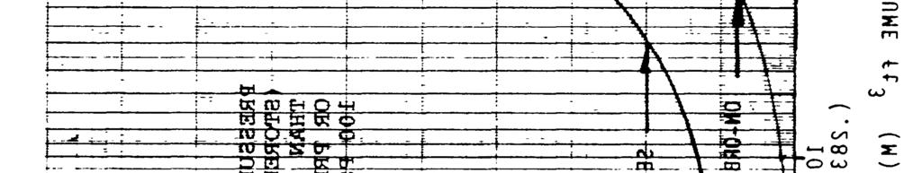
20 3.29 LINES - Lines are tubular elements of a Pressurized system provided as a means for transferring fluids between components of the system. Included in this definition are flex hoses LOAD SPECTRUM - The load spectrum on a structure is a representation of the cumulative static and dynamic loadings anticipated for the structure under all expected operating environments MARGIN OF SAFETY - The margin of safety of a structure is the increment by which the allowable load (or stress) exceeds the applied load (or stress), for a specific design condition, expressed as a fraction of the applied load (or stress). Margin of Safety = ALLOWABLE LOAD (OR STRESS) = 1 APPLLIED LOAD (OR STRESS) 3.32 MAXIMUM ALLOWABLE WORKING PRESSURE (MAWP) - The maximum pressure at which a component can continuously operate based on allowable stress values and functional capabilities. MAWP is synonymous with MDOP (Maximum Design Operating Pressure) or Rated Pressure MAXIMUM OPERATING PRESSURE (MOP) (MEOP) - The maximum pressure at which the system or component actually operates in a particular application. MOP is synonymous with MEOP (Maximum Expected Operating Pressure) or maximum working pressure. MOP includes the effects of temperature, transient peaks, vehicle acceleration, and relief valve tolerance PRESSURE CYCLE - A pressure cycle is a pressure increase greater than the threshold pressure (PTH) followed by a pressure decrease greater than the pth unless otherwise specified PRESSURE VESSEL A pressure vessel is a component of a pressurized system designed primarily as a container that stores pressurized fluids and: (1) Contains stored energy of 14,240 foot-pounds (19,310 joules) or greater based on adiabatic expansion of a perfect gas, Figure 1; Table I; or (2) Contains a gas or liquid which will create a mishap (accident) if released; or (3) Will experience a design limit pressure greater than 100 psi. 8
21
22 NOTE: energy feet. To obtain the pressure vessel equivalent, multiply the equivalent per cubic foot by the vessel volume in cubic 10
23 3.36 PRESSURIZED STRUCTURE - A pressurized structure is a structure designed both to carry internal pressure and vehicle structural loads PRESSURIZED SYSTEM - A pressurized system, as addressed in this document, comprises the pressure vessels or pressurized structure, lines, fittings, valves, etc., that are exposed to and designed by the pressure within these components. It does not include electrical control devices, etc., required to operate the system PROOF FACTOR - The proof factor is a multiplying factor applied to the limit load or MEOP to obtain proof load or proof pressure, for use in acceptance testing PROOF PRESSURE - The proof pressure is the test pressure that pressurized components shall sustain without detrimental deformation. The proof pressure is used to give evidence of satisfactory workmanship and material quality, and/or establish maximum initial flaw sizes. It is equal to the product of maximum expected operating pressure, proof pressure design factor, and a factor accounting for the difference in material properties between test and design temperature QUALIFICATION TESTS - Qualification tests are formal contractual demonstrations that the design, manufacturing, and assembly have resulted in hardware conforming to specification requirements RESIDUAL STRESS - Residual stress is a stress which remains in a detail part as a result of manufacturing processing, testing and operation SAFE-LIFE - Safe-life of a structure is the period during which the structure is predicted not to fail in the expected operating environment SERVICE LIFE - The service life of a component or space vehicle is the total life expectancy of the item. The service life starts with the manufacture of the structure and continues through all acceptance testing, handling, storage, transportation, launch operations, orbital operations, refurbishment, retesting, reentry or recovery from orbit, and reuse that may be required or specified for the item STABILIZING PRESSURE - Any pressure which produces tensile stresses in a pressurized structure is a stabilizing pressure. 11
24 3.45 STIFFNESS - The stiffness of a structure is its resistance to deflection under an applied load STRESS-CORROSION CRACKING - Stress-corrosion cracking is a mechanical-environmental induced failure process in which sustained tensile stress and chemical attack combine to initiate and propagate a flaw in a metal part STRESS INTENSITY FACTOR (K1) - The stress intensity factor is a parameter that describes the elastic stress field in the vicinity of a crack tip THRESHOLD PRESSURE (pth) - Threshold pressure is a pressure change great enough to induce a stress which affects the flaw growth in a pressure vessel THERMAL STRESS - Thermal stress is a structural stress arising from temperature gradients and/or differential thermal deformation in or between structural components, assemblies, or systems THRESHOLD STRESS INTENSITY FACTOR (XTH) - The threshold stress intensity factor is the maximum value of the stress intensity factor below which environmentally induced flaw-growth, under sustained static tensile - stress, does not occur for a given material in a specified environment ULTIMATE LOAD - The ultimate load is the product of the limit load and the ultimate factor of safety. It is the maximum load which the structure must withstand without rupture or collapse in the expected operating environments ULTIMATE FACTOR OF SAFETY - The ultimate factor of safety of structure is the ratio of the ultimate load to the limit load ULTIMATE PRESSURE - The ultimate pressure is the product of the MEOP and the ultimate pressure factor. It is the maximum pressure which the structures must withstand without rupture in the expected operating environment ULTIMATE PRESSURE FACTOR - The ultimate pressure factor is a multiplying factor applied to the MEOP to obtain ultimate pressure VERIFICATION/RE-CERTIFICATION TESTS - Verification/re-certification tests are tests conducted to verify/recertify the integrity of structures after some specific period of operation or storage or after exposure to some adverse conditions. 12
25 SECTION 4 GENERAL REQUIREMENTS This section presents general requirements for the analysis, design and verification of pressure vessels and pressurized structures. Included are requirements on system analysis, structural design, material selection, safe operating stress levels, fracture control, quality assurance and other special requirements. Pressure vessels and pressurized structures shall comply with the requirements specified in Section 4. Pressure vessels and pressurized structures designed fabricated, inspected, and tested in accordance with the ASME Boiler and Pressure Vessel Code, Section VIII Divisions 1 or 2, Section X; or (for GSE only) Title 49 Code of Federal Regulation shall comply with system analysis requirements (Section 4.1) only. 4.1 SYSTEM ANALYSIS REQUIREMENTS System Analysis. Perform a detailed system functional analysis to determine that the operation, interaction, or sequencing of components shall not lead to unsafe conditions which could cause personnel injury or major damage to the vehicle, its booster, or associated ground equipment. The analysis shall identify any single malfunction or personnel error in operation of any component that will create conditions leading to an unacceptable risk to operating personnel or equipment. The analysis shall also evaluate any secondary or subsequent occurrence, failure, or component malfunction which, initiated by a primary failure, could result in personnel injury. Such items identified by the analysis shall be designated safety critical and will require the following considerations. a. Specific Design Action b. Special Safety Operating Requirements c. Specific Hazard Identification and Proposed Corrective Action d. Special Safety Supervision Systems analysis data. Systems analysis data will show that: a. The system provides the capability of maintaining all pressure levels in a safe condition in the event of interruption of any process or control sequence at any time during test or countdown.
26 b. Redundant pressure relief devices have mutually independent pressure escape routes. 4.2 c. In systems where pressure regulator failure may involve critical hazard to the crew or mission success, regulation is redundant and where passive redundant systems are specified includes automatic switchover. d. When the hazardous effects of safety critical failures or malfunctions are prevented through the use of redundant components or systems, it shall be mandatory that all such redundant components or systems are operational prior to the initiation of irreversible portions of safety critical operations or events. GENERAL DESIGN REQUIREMENTS Loads, Pressures and Environments. The entire anticipated load -pressure-temperature history and associated environments throughout the service life shall be determined in accordance with specified mission requirements. As a minimum, the following factors and their statistical variations shall be considered : a. The environmentally induced loads and pressures. b. The environments acting simultaneously with these loads and pressures with their proper relationships. c* The frequency of application of these loads, pressures, environments and their levels and duration. These data shall be used to define the design spectra which shall be used for both design analysis and testing. The design spectra shall be revised as the structural design develops and the loads analysis matures Strength Requirements. All pressure vessels and pressurized structures within the structural system shall possess sufficient strength to withstand limit loads and internal pressures in the expected operating environments throughout their respective service lives without experiencing detrimental deformation. They shall also withstand ultimate loads and internal pressures in the expected operating environments without experiencing rupture or collapse. 14
27 Pressure vessels and pressurized structures shall be capable of withstanding ultimate external loads and ultimate external pressures (destabilizing) without collapse or rupture when internally pressurized to the minimum anticipated operating pressure. All pressure vessels and pressurized structures shall sustain proof pressure without incurring gross yielding or detrimental deformation and shall sustain design burst pressure without rupture. When proof tests are conducted at temperatures other than design temperatures, the change in material properties at the proof temperature shall be accounted for in determining proof pressure. Pressurized structures subject to instability modes of failure shall not collapse under ultimate loads nor degrade the functioning of any system due to elastic buckling deformation under limit loads. Evaluation of buckling strength shall consider the combined action of primary and secondary stresses and their effects on general instability, local or panel instability, and crippling. Design loads for buckling shall be ultimate loads, except that any load component that tends to alleviate buckling shall not be increased by the ultimate design factor. Destabilizing pressures shall be increased by the ultimate design factor, but internal stabilizing pressures shall not be increased unless they reduce structural capability. The margin of safety shall be positive and shall be determined b analysis or test at design ultimate and design limit levels, when appropriate, at the temperatures expected for all critical conditions Stiffness Requirements. Pressure vessels and pressurized structures shall possess adequate stiffness to preclude detrimental deformation at limit loads and pressures in the expected operating environments throughout their respective service lives. The stiffness properties of pressure vessels and pressurized structures shall be such as to prevent all detrimental instabilities of coupled vibration modes, minimize detrimental effects of the loads and dynamics response which are associated with structural flexibility, and minimize adverse interaction with other vehicle systems Thermal Requirements. Thermal effects, including heating rates, temperatures, thermal stresses and deformations, and changes in the physical and mechanical properties of the materials of construction shall be considered in the design of all pressure vessels and pressurized structures. These effects shall be based on temperature extremes which simulate those predicted for the operating environment plus a design margin as specified in MIL-STD
28 4.2.5 Stress Analysis Requirements. A detailed and comprehensive stress analysis of each pressure vessel and pressurized structure shall be conducted under the assumption or no crack-like flaws in the structure. The analysis shall determine stresses resulting from the combined effects of internal pressure, ground or flight loads, temperature and thermal gradients. Both primary membrane stresses and secondary bending stresses resulting from internal pressure shall be calculated to account for the effects of design discontinuities, design configuration and structural support attachments. Loads shall be combined by using the appropriate limit or ultimate safety factors on the individual loads and comparing the results to material and/or geometric capabilities. Safety factors on internal pressures shall be as determined in Section 5.0. Safety factors on external (support) loads shall be as assigned to primary structure supporting the pressurized system. Classical solutions are acceptable if the design geometries and loading conditions are sufficiently simple and the results are sufficiently accurate to warrant their application. Finite element or finite difference structural analysis techniques shall be used to calculate the stresses, strains and displacements for complex design geometries and loading conditions. Local structural models shall be constructed, as necessary> to augment the overall structural model in areas of rapidly varying stresses. Minimum material gage as specified in the design drawings shall be used in calculating stresses. The allowable material strengths shall reflect the effects of temperature, thermal cycling and gradients, processing variables, and time associated with the design environments. Minimum margins of safety associated with the parent materials, weldments and heat-affected zones shall be calculated and tabulated for all pressure vessels and pressurized structures along with their locations and stress levels. The margins of safety shall be positive against the strength and stiffness requirements of Section and 4.2.3, respectively. Records of the stress analysis shall be maintained. The analysis shall include the input parameters> data, assumptions) rationales, methods, references, and a summary of significant analysis results, and safe-life analysis. The analysis shall be revised and updated to maintain currency for the life of the program. 16
29 4.2.6 Malfunction. Pressure vessels and pressurized structures are not required to withstand loads, pressures, or environments due to malfunctions that could create conditions outside the maximum expected mission requirements Miscellaneous Requirements. The structural design of all pressure vessels and pressurized structures shall employ proven processes and procedures for manufacture and repair. The design shall emphasize the need for access, inspection, service, replacement, repair and refurbishment. For all reusable pressure vessels and reusable pressurized structures, the structural design shall permit these structures to be maintained in and refurbished to a flightworthy condition. Repaired and refurbished structures shall meet all stipulated conditions of flightworthiness. 4.3 MATERIALS REQUIREMENTS Material Selection. Materials shall be selected on the basis of proven environmental compatibility, material strengths, fracture properties, and service life consistent with the overall program requirements. Material A allowable values shall be used for pressure vessels, and pressurized structures where failure of a single load path would result in loss of structural integrity. For redundant pressurized structures in which failure of a structural element would result in a safe redistribution of applied loads to other load-carrying members, material B allowable may be used. The fracture toughness shall be as high as practicable within the context of structural efficiency and damage tolerance. For pressurized systems to be analyzed with linear elastic fracture mechanics, fracture properties shall be accounted for in material selection. These properties include fracture toughness; threshold values of stress intensity under sustained loading; subcritical flaw-growth characteristics under sustained and cyclic loadings; the effects of fabrication and joining processes; the effects of cleaning agents, dye penetrants, coatings and proof-test fluids; and the effects of temperature, load spectra, and other environmental conditions. Materials which exhibit a low threshold stress intensity value, i~~, in the expected operating environments shall not be used in pressure vessels and pressurized structures unless adequate protection from the operating environments can be demonstrated by tests. If the material has a threshold stress intensity factor, KTH, of less than 60% of the critical stress intensity factor, KIC, under the conditions of its application, it shall be mandatory to show, by a worst case fracture mechanics analysis, that the low allowable threshold stress intensity factor will not precipitate premature structural failure. 17
30 4.3.2 Material Evaluation. The materials selected for design shall be evaluated with respect to material processing, fabrication methods, manufacturing operations, refurbishment procedures and processes, and other pertinent factors which affect the resulting strength and fracture properties of the material in the fabricated as well as the refurbished configurations. (Reference Section 4.5) The evaluation shall ascertain that the mechanical properties, strengths and fracture properties used in design and analyses will be realized in the actual hardware and that these properties are compatible with the fluid contents and the expected operating environments. Materials which are susceptible to stress-corrosion cracking or hydrogen embrittlement shall be evaluated by performing sustained threshold-stress-intensity tests when applicable data are not available Material Characterization. The allowable mechanical properties, strength and fracture properties of all materials selected for pressure vessels and pressurized structures shall be characterized in sufficient detail to permit reliable and high confidence predictions of their structural performance in the expected operating environments unless these properties are available from reliable sources such as MIL-HDBK-5, MIL-HDBK-17, ASTM Standards, AFML/AFFDL Damage Tolerant Design Handbook, MIL Specifications, Aerospace Structural Metals Handbook, and other sources approved by the procuring agency. Where material properties are not available, they shall be determined by test methods approved by the procuring agency. As a minimum, the characterization shall produce the following strength and fracture properties for the parent metals, weldments and heat-affected zones as a function of the fluid contents, loading spectra, and the expected operating environments, including proof-test environments: a. b. Uniaxial tensile yield stress, Cys, and ultimate stress, ~u; Fracture toughness KIC and KTH; and, for pressurized systems to be analyzed with linear elastic fracture mechanics: c. d. e. Sustained-stress flaw-growth data, da/dt VS~K; Cyclic-stress flaw-growth data, da/dn vsbk and load ratio, R; and, Empirical constants associated with the chosen flaw-growth models. 18
31 Uniform test procedures shall be employed for determining material fracture properties as required. These procedures shall conform to recognized standards, such as test specifications of the American Society for Testing and Materials, and the Society of Automotive Engineers. The test specimens and procedures utilized shall provide valid test data for the intended application. Enough tests shall be conducted so that meaningful nominal values of fracture toughness and flaw-growth rate data corresponding to each alloy system, temper, product form, thermal and chemical environments and loading spectra can be established to evaluate compliance with service life requirements of Section 4.4. Test plans and results shall be approved by the procuring agency. 4.4 SAFE-LIFE REQUIREMENTS The safe-life shall be determined by analysis, test, or both and shall be at least four times the specified service life for those pressure vessels and pressurized structures which are not accessible for periodic inspection and repair. For those pressure vessels and pressurized structures which are readily accessible for periodic inspection and repair, the safe-life, as determined by analysis and test, shall be at least four times the interval between scheduled re-certification. All pressure vessels and pressurized structures which require periodic refurbishment to meet safe-life requirements shall be re-certified after each refurbishment by the same techniques and procedures used in the initial certification, unless an alternative re-certification plan has been approved by the procuring agency. 4.5 FABRICATION AND PROCESS CONTROL REQUIREMENTS Proven processes and procedures for fabrication and repair shall be used to preclude damage or material degradation during material processing, manufacturing operations, and refurbishment. In particular, special attention shall be given to ascertain that the melt process, thermal treatment, welding process, forming, joining, machining, drilling, grinding, repair and rewelding operations, etc., P within the state-of-the-art and have been used on similar ha.re. The fracture toughness, mechanical and physical properties of the parent materials, weldments and heat-affected zones shall be within established design limits after exposure to the intended fabrication processes. The machining, forming, joining, 19
32 welding, dimensional stability during thermal treatments, and through-thickness hardening characteristics of the material shall be compatible with the fabrication processes to be encountered. Fracture control requirements and precautions shall be defined in applicable drawings and process specifications. Detailed fabrication instructions and controls shall be provided to insure proper implementation of the fracture control requirements. Special precautions shall be exercised throughout the manufacturing operations to guard against processing damage or other structural degradation. In addition, procurement requirements and controls shall be implemented to insure that suppliers and subcontractors employ fracture control procedures and precautions consistent with the fabrication and inspection processes intended for use during actual hardware fabrication. 4.6 QUALITY ASSURANCE REQUIREMENTS A quality assurance program, based on a comprehensive study of the product and engineering requirements, such as drawings, material specifications, process specifications, workmanship standards design review records, and failure mode analysis, shall be established to assure that the necessary non-destructive inspections and acceptance tests are effectively performed to verify that the product meetsthe requirements of this document. The program shall insure that materials, parts subassemblies, assemblies, and all completed and refurbished r~i are conform to applicable drawings and process specfications; that no damage or degradation has occurred during material processing, fabrication, inspection, acceptance tests, shipping, storage, operational use and refurbishment; and that defects which could cause failure are detected or evaluated and corrected. As a minimum, the following consideration shall be included in structuring the quality assurance program Inspection Plan. An inspection master plan shall be established prior to start of fabrication. The plan shall specify appropriate inspection points and inspection techniques for use throughout the program, beginning with material procurement and continuing through fabrication, assembly, acceptance proof test, operation, and refurbishment, as appropriate. In establishing inspection points and inspection techniques, consideration shall be given to the material characteristics, fabrication processes, design concepts, structural configuration and accessibility for inspection- Designs employing fracture mechanics techniques shall also include inspection for flaws. The flaw geometries shall encompass defects commonly encountered, including surface crack, corner crack, through-the-thickness crack at the edge of
33 fastener hole, surface crack at the edge of bolt hole, and surface crack at the root of intersecting prismatic structural elements. Acceptance and rejection standards shall be established for each phase of inspection, and for each type of inspection technique Inspection Techniques. The selected non-destructive inspection (NDI) techniques must have the capability to determine the size, geometry, location and orientation of a flaw or defect; to obtain, where multiple flaws exist, the location of each with respect to the other and the distance between them; and to differentiate among defect shapes, from tight cracks to spherical voids. Two or more NDI methods shall be used for a part or assembly that cannot be adequately examined by only one method. The flaw detection capability of each selected NDI technique shall be based on past experience on similar hardware. Where this experience is not available or is not sufficiently extensive to provide reliable results, the capability, under production or operational inspection conditions, shall be determined experimentally and demonstrated by tests approved by the procuring agency on representative material product form, thickness, and design configuration. The flaw detection capability shall be expressed in terms of detectable crack length, crack depth, or crack area. To minimize the possibility of proof test failure in pressure vessels the selected NDI technique(s) should be capable of detecting flaws smaller than critical size with a 90% probability of detection at a 95% confidence level. The most appropriate NDI technique(s) for detecting commonly encountered flaw types shall be used for all pressure vessels along with their flaw detection capabilities. The following criteria shall apply in defining the characteristics of part-through initial flaws in the event the selected NDI technique measures either the flaw length or the flaw depth, but not both. The depth of initial flaw shall be assumed to be one-half (1/2) the flaw length if the NDI technique measures only the flaw-length; whereas, for an NDI technique which measures only flaw-depth, the length of flaw shall be assumed to be twenty (20) times the depth Inspection Data. Inspection data in the form of flaw histories shall be maintained throughout the life of the pressure vessel and pressurized structure. These data shall be periodically reviewed and assessed to evaluate trends and anomalies associated with the inspection procedures, equipment 21
34 and personnel, material characteristics, fabrication processes, design concept and structural configuration. The result of this assessment shall form the basis of any required corrective action Acceptance Test. Every pressure vessel, and pressurized structure shall be proof-pressure tested in accordance with the requirements of Section 5.1, 5.2, and 5.3 as applicable to verify that the hardware has sufficient structural integrity to sustain the subsequent service loads, pressure, temperatures and environments. The temperature of the vessel shall be consistent with the critical use temperature, or, as an alternative, tests may be conducted at an alternate temperature if the test pressures are suitably adjusted to account for temperature effects on strength and fracture toughness. Accept/reject criteria shall be formulated prior to acceptance test. Every pressure vessel and pressurized structure shall not leak, rupture or experience gross yielding during acceptance testing. 4.7 OPERATIONS AND MAINTENANCE REQUIREMENTS Operating Procedures. Operating procedures shall be established for each pressure vessel. These procedures shall be compatible with the safety requirements and personnel control requirements at the facility where the operations are conducted. Step-by-step directions shall be written with sufficient detail to allow a qualified technician or mechanic to accomplish the operations. Schematics which identify the location and pressure limits of relief valves and burst disc shall be provided, and procedures to insure compatibility of the pressurizing system with the structural capability of the pressurized hardware shall be established. Prior to initiating or performing a procedure involving hazardous operations with pressure systems, practice runs shall be conducted on non-pressurized systems until the operating procedures are well rehearsed. Initial tests shall then be conducted at pressure levels not to exceed 50% of the normal operating pressures until operating characteristics can be established and stabilized. Only qualified and trained personnel shall be assigned to work on or with high pressure systems. Warning signs with the hazard(s) identified shall be posted at the operations facility prior to pressurization Safe Operating Limits. Safe o crating limits shall be established for each pressure vessel and each pressurized structure based on the appropriate analysis and testing employed in its design and qualification per Section
35 These safe operating limits shall be summarized in a format which will provide rapid visibility of the important structural characteristics and capability. The desired information shall include, but not be limited to, such data as fabrication materials, critical design conditions, MEOP, nominal operating or working pressure, proof pressure, burst pressure, pressurization and depressurization sequence, operational cycle limits, design and operating temperatures, operational s stem fluid, cleaning agent, NDI techniques employed, permissible thermal and chemical environments, minimum margin of safety and potential failure mode. For pressurized systems with potential brittle fracture failure mode, the critical flaw sizes and maximum permissible flaw sizes shall also be included. Appropriate references to design drawings, detail analyses, inspection records, test reports, and other back-up documentation shall be indicated Inspection and Maintenance. The results of the appropriate stress, and safe-life, analyses shall be used in conjunction with the appropriate results from the structural development and qualification tests to develop a quantitative approach to inspection and repair. Allowable damage limits shall be established for each pressure vessel and pressurized structure so that the required inspection interval and repair schedule can be established to maintain hardware to the requirements of this document NDI technique(s) and inspection procedures to reliably detect critical structural defects and determine flaw size under the condition of use shall be specified. Detailed repair procedures shall be developed for use in field and depot levels. Procedures shall be established for recording, tracking, and analyzing operational data as it is accumulated to identify critical areas requiring corrective actions. Analyses shall include prediction of remaining life and reassessment of required inspection intervals Repair and Refurbishment. When inspections reveal structural damage or detects exceeding the permissible levels, the damaged hardware shall be repaired, refurbished, or replaced, as appropriate. All repaired or refurbished hardware shall be re-certified after each repair and refurbishment by the applicable acceptance test procedure for new hardware to verify their structural integrity and to establish their suitability for continued service Storage Requirements. When pressure vessels and pressurized structures are put into storage, they shall be protected against exposure to adverse environments which could cause corrosion or other forms of material degradation. In addition, they shall be protected against mechanical damages resulting from scratches, dents, or accidental dropping of the 23
36 hardware. Induced stresses due to storage fixture constraints shall be minimized by suitable storage fixture design. In the event storage requirements are violated, re-certification shall be required prior to acceptance for use Documentation. Inspection, maintenance, and operation records shall be kept and maintained throughout the life of each pressure vessel and each pressurized structure. As a minimum, the records shall contain the following information: a. b. c. d. e. f. g. h. Temperature, pressurization history, and pressurizing fluid for both tests and operations. Number of pressurizations experienced as well as number allowed in safe-life analysis. Results of any inspection conducted, including: inspector, inspection dates, inspection techniques employed, location and character of defects, defect origin and cause. Storage condition. Maintenance and corrective actions performed from manufacturing to operational use, including refurbishment. Sketches and photographs to show areas of structural damage and extent of repairs. Acceptance and re-certification test performed, including test conditions and results. Analyses supporting the repair or modification which may influence future use capability. 4.8 SPECIAL REQUIREMENTS Re-activated Pressurized Hardware. Pressure vessels and pressurized structures which are re-activated for use after an extensive period in either an unknown, unprotected, or unregulated storage environments shall be re-certified to ascertain their structural integrity and suitability for continued service before commitment to flight. Re-certification tests for pressurized hardware shall be in accordance with the appropriate Re-Certification Test Requirement ( , ). 24
37 4.8.2 Multiple Proof Tests. Multiple proof tests are generally not required or recommended except in special circumstances, as described below: a. Re-activated pressurized hardware as described in Section b. c. d. e. f. g. h. Refurbished or repaired hardware (Section 4.7.4). Hardware modification after the initial proof test. Re-certification of hardware for additional service after it has been in service for its intended safe-life. Re-certification of hardware designed for safe-life between regularly scheduled inspection. Component testing prior to final assembly. Proof test limitation resulting from inability of a single proof test to envelope the critical operational pressure, temperature, and external loading combinations. Proof test limitation resulting from inability of the initial proof test to verify the entire service life capability of the hardware Test Fluids. Proof-test fluids shall be compatible with the structural materials in the pressure vessels and pressurized structures. Proof test fluids shall not pose a hazard to test personnel. If such compatibility data is not available, required testing shall be conducted to demonstrate that the proposed test fluid does not have a deleterious effect on the article to be tested. 25
38 THIS PAGE INTENTIONALLY LEFT BLANK (FOR PAGING PURPOSES) 26
39 SECTION 5 DETAILED REQUIREMENTS Four approaches for the design, analysis and verification of pressure vessels are offered as illustrated in Figure 2. Selection of the approach to be used is dependent on the desired efficiency of design coupled with the level of analysis and verification testing required. Final selection shall be coordinated and/or defined by the procuring agency and the appropriate launch or test range approval authority. Approach A, Figure 2, illustrates the steps required for verification of a pressure vessel designed with a burst factor equal to 1.5 or greater. This approach is not acceptable for the design and verification of ground support equipment. Based on the results of the failure mode determination, one of two distinct verification paths must be satisfied: 1) Leak-Before-Burst with leakage of the contents not creating a condition which could lead to a mishap (such as toxic gas venting or pressurization of a compartment not capable of the pressure increase), and 2) Brittle failure mode or Leak-Before-Burst in which, if allowed to leak, the leak causes a hazard. The verification requirements for path 1 are delineated in Sections and 5.2.1, and the verification requirements for path 2 in Sections and Approach B, Figure 2, illustrates the steps required for verification of a pressure vessel designed with a burst factor equal to 2.0 or greater. This approach is not acceptable for USAF/SD use, or design and verification of ground support equipment. Verification requirements for this approach are delineated in Sections and Approach C, Figure 2, illustrates the steps required for verification of a pressure vessel designed employing the ASME Boiler and Pressure Vessel Code. This approach is the only acceptable approach for ground support equipment. Additional requirements for airborne vehicle equipment and ground support equipment are delineated in Sections and NON-COMPOSITE PRESSURE VESSELS This section is intended primarily for application to metallic pressure vessels but may be used for certain non-metallics with the approval of the procuring agency (for fiber reinforced composite pressure vessels, see Section 5.2). 27
40
41 5.1.1 Pressure Vessels with Non-Hazardous Leak-Before-Burst(LBB) Failure Mode (Aerospace Vehicle Equipment, AVE). The LBB failure mode shall be demonstrated analytically or by test showing that an initial flaw of any size, considering a flaw shape range of.05 z a/2c z.5, will propagate through the thickness of the pressure vessel before becoming critical. (See the Appendix for an acceptable analytical approach) Factor of Safety Requirements. Pressure vessels which satisfy the LBB failure mode criterion may be designed conventionally, wherein the design factors of safety and test factors are selected on the basis of successful past experience or specified by codes and specifications. Unless otherwise specified, the minimum Design Burst Factor shall be Safe-Life Analysis Requirements. In addition to the stress analysis conducted in accordance with the requirements of-section 4.2.5, conventional fatigue-life analysis shall be performed, as appropriate, on the unflawed structure to ascertain that the pressure vessel, acted upon by the spectra of maximum expected operating loads, pressures and environments will meet the safe-life requirements of Section 4.4. Nominal values of fatigue-life characteristics of the structural materials shall be taken from reliable sources such as MIL-HDBK-5, ASTM Standards, MIL Specifications, the Aerospace Structural Metals Handbook, or other sources approved by the procuring agency. Safe-life requirements are met when Minor s rule, expressed as is satisfied. In this equation, ni = 4 times the number of cycles applied at stress level i, Ni = the number of cycles to failure at stress level i, and k = number of stress levels considered in the analysis. The LBB failure mode criteria accepts the possibility of propagation of an existing flaw, through the thickness of the vessel wall, allowing leakage of the contained gas or liquid. In the event that this leakage would present a hazard, fracture mechanics analysis shall be required. (See Section ) Qualification Test Requirements. Qualification tests shall be conducted on flight-quality hardware to demonstrate structural adequacy of the design. The test fixtures, support structures, and methods of environmental application shall not induce erroneous test conditions. The types of instrumentation and their locations in qualification 29
42 tests shall be based on the results of the stress analysis of Section The instrumentation shall provide sufficient data to ensure proper application of the accept/reject criteria, which shall be established prior to test. The sequences, combinations, levels, and duration of loads, pressure and environments shall demonstrate that design requirements have been met. Qualification testing shall include demonstration of the leak-before-burst failure mode by pre-flawed specimen testing, fatigue life by cycle testing and random vibration testing and ultimate strength by burst testing. The following delineates the required tests: a. Leak before burst testing The test may be conducted on coupons which duplicate the materials (parent material, weldment, and HAZ) and thicknesses of the pressure vessel or on a pressure vessel representative of the flight hardware. Test specimens shall be pre-flawed and cycled through the design spectrum to demonstrate stable flaw growth completely through the wall thickness. A sufficient number of tests is to be conducted to establish that all areas (thicknesses) and stress fields will exhibit a leak-before-burst mode of failure. This test may be partially or completely omitted if available materials data, directly applicable to the materials and methods of construction, are available to substantiate an analytical demonstration of the leak-before-burst failure mode. b. Pressure Testing Required qualification pressure testing levels are shown in Table II. Requirement for application of external loads in combination with internal pressures during testing must be evaluated based on the relative magnitude and/or destabilizing effect of stresses due to the external load. If limit combined tensile stresses are enveloped by test pressure stresses, the application of external loads shall not be required. If the application of external loads is required, the load shall be cycled to limit for four times the predicted number of operating cycles of the most severe design condition (eg. destabilizing load with constant minimum internal pressure or maximum 30
43 additive load with constant maximum expected operating pressure). Qualification test procedure shall be approved by the procuring agency and the appropriate launch or test range approval authority. c. Random Vibration Testing Random Vibration qualification testing shall be performed per requirements of MIL-STD-1540 unless it can be shown the vibration requirement is enveloped by other qualification testing performed Acceptance Test Requirements. Acceptance tests shall be conducted on every pressure vessel before commitment to flight. Accept/reject criteria shall be formulated prior to tests. The test fixtures and support structures shall be designed to permit application of all test loads without Jeopardizing the flightworthiness of the test article. The following are required as a minimum. a. Non-Destructive Inspection. A complete inspection by the selected non - destructive inspection (NDI) technique(s) shall be performed prior to proof pressure test to establish the initial condition of the hardware. All pressurized hardware which requires periodic refurbishment to meet safe-life requirements shall undergo a complete postrefurbishment inspection prior to additional proof pressure tests. b. Proof Pressure Test. Every pressure vessel shall be proof-pressure tested to verify that the materials, manufacturing processes, and workmanship meet design specifications and that the hardware is suitable for flight. The proof pressure shall be equal to: proof = (1 + Burst Factor)/2 x MEOP or 1.5 x (MEOP) whichever is lower Re-Certification Test Requirements. All refurbished pressure vessels shall be re-certified after each refurbishment by the acceptance test requirements for new hardware to verify their structural integrity and to establish their suitability for continued service before commitment to flight. Pressure vessels which have exceeded the approved storage environment (temperature, humidity, time etc.) shall also be re-certified by the acceptance test requirements for new hardware. 31
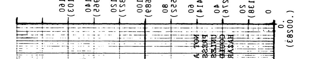
44 TABLE II. Qualification Test Requirements Pressure Vessels with Brittle Fracture or Hazardous Leak-Before-Burst (LBB) Failure Mode (AVE) Factor of Safety Requirements. Safe-life design methodology based on fracture mechanics techniques shall be used to establish the appropriate design factor of safety and the associated proof factor for pressure vessels which exhibit brittle fracture or hazardous leak-before-burst failure mode. The loading spectra, material strengths, fracture toughness and flaw-growth rates of the parent material and weldments, test program requirements, stress levels, and the compatibility of the structural materials with the thermal and chemical environments expected in service shall be taken into consideration. Nominal values of fracture toughness and flaw-growth rate data corresponding to each alloy system, temper and product form shall be used along with a life factor of four on specified service life in establishing the design factor of safety and the associated proof factor. Unless otherwise specified the minimum burst factor shall be
45 Safe-life Demonstration Requirements. In addition to the stress analysis conducted in accordance with the requirements of Section 4.2.5, safe-life analysis of each pressure vessel covering the maximum expected operating loads and environments, shall be performed under the assumption of pre-existing initial flaws or cracks in the vessel. In particular, the analysis shall show that the pressure vessel with flaws placed in the most unfavorable orientation with respect to the applied stress and material properties, of sizes defined by the acceptance proof test or NDI and acted upon by the spectra of maximum expected operating loads and environments, will meet the safe-life requirements of Section 4.4. Nominal values of fracture toughness and flaw-growth rate data associated with each alloy system, temper, product form, thermal and chemical environments, and loading spectra shall be used along with a life factor of four on specified service life in all safe-life analyses. Pressure vessels which experience sustained stress shall also show that the corresponding applied stress intensity (K1) during operation is less than the threshold stress intensity (KTH) in the appropriate environment If the above cannot be shown: then analysis must show flaw growth to failure or.9t, whichever is less, will not occur during four times the time interval for which the pressure vessel is a hazard (eg. pressurized in the STS cargo bay). The safe-life analysis shall be included in the stress analysis of Section In particular, the fracture mechanics data, loading spectra and environments, flaw-growth model, initial flaw sizes, proof factors, strength and other input data, analysis assumptions, rationales, methods, references, summary of significant results, shall be clearly presented. Testing of structure under fracture control in lieu of safe-life analysis is an acceptable alternative, provided that, in addition to following a quality assurance program (Section 4.6) for each flight article, a qualification test program is implemented on pre-flawed specimens representative of the structure design. These flaws shall not be less than the flaw sizes established by the acceptance proof test or the selected NDI method(s). Safe-life requirements of Section 4.4 are considered demonstrated when the pre-flawed test specimens successfully sustain the limit loads and pressures in the expected operating environments for the specified test duration without rupture. 33
46 Qualification Test Requirements. Qualification tests shall be conducted on flight-quality hardware to demonstrate structural adequacy of the design. The test fixtures, support structures, and methods of environmental application shall not include erroneous test conditions. The types of instrumentation and their locations in qualification tests shall be based on the results of the stress analysis of Section The instrumentation shall provide sufficient data to ensure proper application of the accept/reject criteria, which shall be established prior to test. The sequences, combinations, levels, and duration of loads, pressure and environments shall demonstrate that design requirements have been met. Qualification testing shall include life cycle testing, random vibration testing, and burst testing. The following delineates the required tests: a. Pressure Testing Required qualification pressure testing levels are shown in Table II. Requirement for application of external loads in combination with internal pressures during testing must be evaluated based on the relative magnitude and/or destabilizing effect of stresses due to the external load. If limit combined tensile stresses are enveloped by test pressure stresses, the application of external loads shall not be required. If the application of external loads is required, the load shall be cycled to limit for four times the predicted number of operating cycles of the most severe design condition (e.g., destabilizing load with constant minimum internal pressure, or maximum additive load with constant maximum expected operating pressure). Qualification test procedure shall be approved by the procuring agency and the appropriate launch or test range approval authority. b. Random Vibration Random vibration qualification testing shall be performed per requirements of MIL-STD-1540 unless it can be shown the vibration requirement is enveloped by other qualification testing performed Acceptance Test Requirements. The acceptance test requirements for pressure vessels which exhibit brittle fracture, or hazardous LBB, failure mode are identical to those with ductile fracture failure mode as defined in Section except that the test level shall be that defined by the fracture
47 mechanics analysis. Cryo-proof acceptance test procedures may be required to adequately verify initial flaw size. The pressure vessel shall not rupture or leak at the acceptance test pressure Re-certification Test Requirements. All refurbished pressure vessels shall be re-certified after each refurbishment by the acceptance test requirements for new hardware to verify their structural integrity and to establish their suitability for continued service before commitment to flight. Pressure vessels which have exceeded the approved storage environment (temperature, humidity, time etc.) shall also be re-certified by the acceptance test requirements for new hardware Pressure Vessels Designed Employing Strength of Materials (AVE). Pressure vessels may be designed and verified utilizing the following criteria which does not employ fracture mechanics techniques. Pressure vessel failure mode demonstration is not required. The DoD user of this approach should be aware that this approach is not acceptable for USAF/SD use. The pressure vessel is to be designed, analyzed and verified as defined in Section with the following exceptions or changes to criteria Factor of Safety Requirements - The pressure vessel is to be designed to a minimum Proof Pressure = 1.5 x MEOP and a minimum Design Burst Pressure = 2.0 x MEOP Safe-Life Analysis Requirements - Requirements per Section Qualification Test Requirements - Requirements per Section except that Leak Before Burst testing is deleted Acceptance Test Requirements - Requirements per Section except that proof test shall be conducted at 1.5 x MEOP , Re-Certification Test Requirements- Requirements per Section > Pressure Vessels Designed Employing the ASME Boiler Code (AVE & GSE). Pressure vessels may be designed and manufactured per the rules of the ASME Boiler and Pressure Vessel Code, Section VIII, Divisions 1 or 2. 35
48 Qualification Test Requirements - (For airborne systems required to satisfy Space Transportation System Safety Requirements). Qualification testing shall consist of the cycle testing defined in Section b Acceptance Test Requirements - As specified in Code. AVE pressure vessels shall be proof pressure tested at 105 x MEOP. This test may be accomplished when satisfying code requirements Re-Certification Requirements (GSE) - When no data is available concerning existing ground system pressure vessel or history of use, or if the origin of data is uncertain, perform a detailed investigation to determine the utility of the vessel. This investigation shall, as a minimum, include the following: (a) Paint removal and thorough internal and external surface cleaning including removal of corrosion. (b) Thorough internal and external surface inspection to determine extent of corrosion or any handling damage or cracks. (c) Accurate measurement of minimum vessel wall thickness. (d) Identification of construction materials. (e) Determination of operating stress levels using proposed system maximum expected operating pressure. (f) Analysis to determine the operating safety factor based on corrosion or other existing damage. (g) Hydrostatic test to 150% of proposed maximum expected operating pressure. (h) The using activity above investigation as 5.2 COMPOSITE PRESSURE VESSELS shall maintain reports of the a part of the system records. Pressure vessels fabricated of composite materials must satisfy the non-composite requirements of Section 5.1 with the following exceptions applicable to each design verification analysis approach. 36
49 Composite vessels with metallic liners may be designed employing either of the two approaches. Composite vessels without a load carrying metallic liner may only be designed by the ASME code, (section of this standard). The leak-before-burst or brittle failure mode designation for a metal lined composite vessel shall be based on the characteristics of the liner. Fracture mechanics methodology is not applicable to the composite overwrap Composite Pressure Vessels with Non-Hazardous Leak-Before-Burst (LBB) Failure Mode (AVE). Applicable fracture mechanics analysis and/or tests of metal lined composite pressure vessels shall verify the leak-before-burst failure mode of the metal liner Factors of Safety Requirements. Requirements per Section Safe-Life Analysis Requirements. Requirements per Section Qualification Test Requirements. Qualification testing shall consist of the leak-before-burst demonstration of the liner and cycle/burst testing of the composite vessel as defined in Section In particular the effects of the liner sizing operation on the fracture mechanics characteristics of the liner should be accounted for in the LBB evaluation Acceptance Test Requirements. Acceptance tests shall be conducted as defined in Section The substitution of the metal liner sizing operation for acceptance test is acceptable provided the requirements of Section are satisfied Re-Certification Test Requirements. Requirements per Section (NOTE) Alternate re-certification procedure may be approved by the procuring and safety agencies Composite Pressure Vessels with Brittle Fracture or Hazardous LBB Failure Mode (AVE). This section is applicable only to composite pressure vessels with metal liners which exhibit brittle fracture or hazardous leak-before-burst failure mode Factor of Safety Requirements. Unless otherwise specified, the minimum burst factor shall be
50 Safe - Life Demonstration Requirements. Requirements of Section shall apply to the metal liner. Conventional fatigue life analysis of the composite overwrap must verify the liner is the critical safe-life component. Analysis shall show the safe-life of the overwrap to be a factor of 10 longer than the safe-life of the liner Qualification Test Requirements. Requirements per Section Acceptance Test Requirements. Acceptance test requirements shall be as defined in Section The substitution of metal liner sizing operation for an acceptance test is acceptable provided the requirements of Section are satisfied. The metal liner shall not leak at the proof test pressure. An additional Cryo type proof test of the liner, prior to composite overwrap, may be required to adequately verify the largest allowable initial flaw size present in the liner Re-certification Test Requirements. The re-certification test requirements for all refurb ifshed composite pressure vessels are as defined in Section Composite Pressure Vessels Designed Employing Strength of Materials (AVE). Composite pressure vessels, both load bearing metal Lined and all composite, may be designed and verified utilizing the criteria of Section which does not employ fracture mechanics techniques Composite Pressure Vessels Designed Employing the ASME Boiler Code (AVE & GSE). Composite pressure vessels may e designed and manufactured per the rules of the ASME Boiler and Pressure Code, Section X Qualification Test Requirements. (For airborne systems required to satisfy Space Transportation System Requirements). Qualification testing shall consist of the cycle testing defined in Section b and random vibration testing defined in Section c, Acceptance Test Requirements. AS specified in Code. AVE pressure vessels shall be proof pressure tested at 1.5 x MEOP. This test may be accomplished when satisfying code requirements. 5.3 COMPONENTS Factors of Safety Requirements - Components excluding pressure vessels are to be designed to the minimum factors given in Table III. 38
51 TABLE III. Systems Safety Factors Safe-Life Analysis Requirements. Not required Qualification Test Requirements. Not required on lines and fittings. Internal/ external pressure testing shall be conducted on all other components to demonstrate no failure at the design burst pressure Acceptance Test Requirements. Acceptance test requirements shall be satisfied by completion of leak and/or proof test requirements for the assembled pressurized system as dictated by the applicable range safety documentation, and or procuring agency, requirements Re-Certification Test Requirements. Re-certification of lines, fittings and components shall be as delineated in Section as applied to the refurbished systems. 39
52 THIS PAGE INTENTIONALLY LEFT BLANK (FOR PAGING PURPOSES) 40
53 SECTION 6 PRESSURIZED SYSTEM REQUIREMENTS Requirements which apply to all types of pressurized systems are in section 6.1. Additional detail requirements applicable to specific system types are in the sections following. 6.1 GENERAL PRESSURIZED SYSTEM REQUIREMENTS Design Features Assembly. Design components so that, during the assembly of parts, sufficient clearance exists to permit assembly of the components without damage to O-rings or backup rings where they pass threaded parts or sharp corners Routing. Avoid straight tubing and piping runs between two rigid connection points. Where such straight runs are necessary, provisions shall be made for expansion joints, motion of the units, or similar compensation to insure that no excessive strains will be applied to the tubing and fittings. Use line bends to ease stresses induced in tubing by alignment tolerances and vibration Separation. Physically separate redundant pressure components and systems from main systems for maximum safety advantage in case of damage or fire Shielding. Shield pressure systems from other systems when required to minimize all hazards caused by proximity to combustible gases, heat sources, electrical equipment, etc. Any failure in any such adjacent system shall not result in combustion or explosion of pressure fluids or components. Shield or separate lines, drains, and vents from other high-energy systems; for example, heat, high voltage, combustible gases, and chemicals. Drain and vent lines will not be connected to any other lines in any way that could generate a hazardous mixture in the drain/vent line, or allow feedback of hazardous substances to the components being drained or vented. Shield or isolate pressure fluid reservoirs from combustion apparatus or other heat sources Grounding. Electrically ground hydraulic system components and lines to metallic structures Handling. Provide fixtures for safe handling and hoisting with coordinated attachment points in the system structure, for equipment that cannot be hand-carried. Handling and hoisting loads shall be in accordance with MIL-S
54 Special Tools. Design safety critical pressure systems so that special tools shall not be required for removal and replacement of components unless it can be shown that the use of special tools is unavoidable Test Points. Provide test points if required, such that disassembly for test is not required. The test points shall be easily accessible for attachment of ground test equipment Common-Plug Test Connectors. Common-plug test connectors for pressure and return sections shall be designed to require positive removal of the pressure connection prior to unsealing the return connections Individual Pressure and Return Test Connectors. Individual pressure and return test connectors shall be designed to positively prevent inadvertent cross-connections Threaded Parts. All threaded parts in safety critical components shall be securely locked to resist uncoupling forces by acceptable safe design methods. Safety wiring and self-locking nuts are examples of acceptable safe design. Torque for threaded parts in safety critical components shall be specified Friction Locking Devices. Avoid friction-type locking devices in safety critical applications. Star washers and jam nuts shall not be used as locking devices Internally Threaded Bosses. The design of internally threaded bosses shall preclude the possibility of damage to the component or the boss threads because of screwing universal fittings to excessive depths in the bosses Retainer or Snap Rings. Retainer or snap rings shall not be used in pressure systems where failure of the ring would allow connection failures or blow-outs caused by internal pressure Snubbers. Snubbers shall be used with all Bourdon type pressure transmitters, pressure switches, and pressure gages, except air pressure gages Component Selection Connections. Design or select components to assure that hazardous disconnections or reverse installations within the subsystem are not possible. Color codes, labels, and directional arrows, are not acceptable as the primary means for preventing incorrect installation. 42
55 Fluid Temperature. Estimate the maximum fluid temperature early in design as part of data for selection of safety critical components, such as system fluid, pressurizing gas, oil coolers, gaskets, etc Actuator Pressure Rating. Specify components that are capable of safe actuation under pressure equal to the maximum relief valve setting in the circuit in which they are installed Pressure Service Ratings. Pumps, valves/regulators, hoses, and all such prefabricated components of a pressure system shall have proven pressure service ratings equal to or higher than the limit-load (maximum expected operating pressure) and rated service life of the system Pump Selection. Apply "The Standards of the Hydraulic Institute" in evaluating safety in pump selection Fracture and Leakage. Where leakage or fracture is hazardous to personnel or critical equipment, design so that failure occurs at the outlet threads of valves before the inlet threads or body of the valve fails under pressure Oxygen System Components. Specify valves and other components for oxygen systems of 3000 psi or higher that are slow opening and closing types to minimize the potential for ignition of contaminants. Such systems shall also require electrical grounding to eliminate the possibility of the build-up of static electrical charges Pressure Regulators. Select pressure regulators to operate in the center 50 percent of their total pressure range, or design to avoid creep and inaccuracies at either end of the full operating range Flareless Tube Fittings. In all cases flareless tube fittings shall be properly preset prior to pressure application Manual Valves and Regulators. Design manually operated valves and regulators so that over torqueing of the valve stem or regulator adjustment cannot damage soft seats to the extent that failure of the seat will result Valve designs which utilize uncontained seats are unacceptable and shall not be specified. 43
56 6.1.3 Design Pressures Over Pressure. Specify warning devices to indicate hazardous over or under pressures to operating personnel. These devices shall actuate at predetermined pressure levels designed to allow time for corrective action Back Pressure. Safety critical actuations of pneumatic systems shall not be adversely affected by any back pressure resulting from concurrent operations of any other parts of the system under any set of conditions Pressure Isolation. Components or lines that can be isolated and contain residual pressure shall be equipped with gage reading and bleed valves for pressure safety check. Bleed valves shall be directed away from operating personnel. Fittings or caps for bleeding pressure are not acceptable Gas/Fluid Separation. Specify pressurized reservoirs that are designed for gas/fluid separation with provision to entrap gas that may be hazardous to the system or safety critical actuation, and prevent its recirculation in the system. This shall include the posting of instructions adjacent to the filling point for proper bleeding when servicing Compressed Gas Bleeding. Bleed compressed gas emergency systems directly to the atmosphere away from the vicinity of personnel, rather than to reservoir. If the gas is combustible, consideration should be given to methods for reducing the potential for accidental ignition or explosion Design Loads Acceleration and Shock Loads. Specify installation of all lines and components to withstand all expected acceleration and shock loads. Shock isolation mounts may be used if necessary to eliminate destructive vibration and interference collisions Torque Loads. Specify the mounting of components, including valves, on structures having sufficient strength to withstand torque and dynamic loads, and not supported by the tubing. However, light-weight components that do not require adjustment after installation (for example, check valves), may be supported by the tubing, provided that a tube clamp is installed on each such tube near the component Vibration Loads. Support tubing by cushioned steel tube clamps or by multiple-block type clamps that are suitably spaced to restrain destructive vibration. 44
57 6.1.5 Controls Interlocks. Specify interlocks where necessary to prevent a hazardous sequence of operations and provide a fail-safe capability at all times. For example, the "open" position of remotely controlled valves that can hazardously pressurize lines leading to remotely controlled (or automatic) disconnect couplings shall be interlocked to preclude the "open" valve position coincident with the disconnected condition of the couplings Multiple Safety Critical Functions. Pressure systems that combi ne several safety critical functions shall have sufficient controls for isolating failed functions, for the purpose of safely operating the remaining functions Critical Flows and Pressures. All pressure systems shall have pressure indicating devices to monitor critical flows and pressures marked to show safe upper and lower limits of system pressure. The pressure indicators shall be so located as to be readily visible to the operating crew Protection. Protect all systems for pressure above 500 psi in all areas where damage can occur during servicing or other operational hazards. Hazardous piping line routes that invite use as handholds or climbing bars, shall be avoided. Shield pressure lines and components of 500 psi or higher that are adjacent to safety critical equipment to protect such equipment in the event of leakage or burst of the pressure system Electrical Hazardous Atmospheres. Electric components for use in potentially ignitable atmospheres shall be demonstrated to be incapable of causing an explosion in the intended application Radio Frequency Energy. Electrically energized h draulic components shall not propagate radio-frequency energy that is hazardous to other subsystems in the total system, or interfere in the operation of safety critical electronic equipment (Reference MIL-E-6051) Grounding. Electrically ground pressure system components and lines to metallic structures Solenoids. All solenoids shall be capable of safely withstanding a test voltage of not less than 1500 V rms at 60 cps for 1 minute between terminals and case at the maximum operating temperature of the solenoid in the functional envelope. 45
58 29 MAY Electric Motor Driven Pumps. Electric motor driven pumps used in safety critical systems shall not be used for ground test purposes unless the motor is rated for reliable continuous and safe operation. Otherwise, the test parameters may perturb reliability calculations Pressure Relief Requirement. Specify pressure relief devices on all systems having a pressure source which can exceed the maximum allowable pressure of the system, or where the malfunction/failure of any component can cause the maximum allowable pressure to be exceeded. Relief devices are required downstream of all regulating valves and orifice restrictors unless the downstream system is designed to accept full source pressure. On space systems, where operational or weight limitations preclude the use of relief valves, and systems will operate in an environment not hazardous to personnel, they can be omitted if the ground or support system contains such devices and they cannot be isolated from the airborne system during the pressurization cycle and the space vehicle cannot provide its own protection Flow Capacity. Specify that all pressure relief devices shall provide relief at full flow capacity at 110% of the MEOP of the system, or lower Sizing. Specify the size of pressure relief devices to withstand maximum pressure and flow capacities of the pressure source, to prevent pressure from exceeding 110% of the MEOP of the system Unmanned Flight Vehicle Servicing. Where a round system is specifically designed to service an unmanned flight vehicle, pressure relief protection may be provided within the ground equipment, if no capability exists to isolate the pressure relief protection from the flight vehicle during the pressurization cycle Automatic Relief Low Safety Factor. Where safety factors less than 2.0 are used in the design of pressure AVE vessels, provide a means for the automatic relief, depressurization, and pressure verification of safety critical vessels for the event of launch abort Confinement. Whenever any pressure volume can be confined and/or isolated by system valving. provide an automatic pressure relief device. Pop-valves, rupture discs, 46
59 blow-out plugs, armoring, and construction to contain the greatest possible overpressure that may develop are examples of corrective measures for system safety in cases not covered by the above paragraphs Venting. Vent pressure relief devices for toxic or inert gases to safe areas or scrubbers, away from the vicinity of personnel Relief Valve Isolation. Shut-off valves for maintenance purposes on the inlet side of pressurized relief valves are permissible if a means for monitoring and bleeding trapped pressure is provided and the requirements of ASME Code for unfired pressure vessels, Appendix M, paragraph UA-354, and the provisions for valve design in paragraph are met. It is mandatory that the valve be locked open when the system is repressurized Negative Pressure Protection Testing. Hydrostatic testing systems for vessels which are not designed to sustain negative internal pressure shall be equipped with fail-safe devices for relief of hazardous negative pressure during the period of fluid removal. Check valves and valve interlocks are examples of devices which can be used for this purpose Storage and Transportation. Thin walled vessels which can be collapsed by a negative pressure shall have negative pressure relief and/or prevention devices for safety during storage and transportation Reservoir Pressure Relief. Design pressurized reservoirs so that ull age volumes shall be connected to a relief valve that shall protect tune reservoir and power pump from hazardous overpressure or back pressure of the system Air Pressure Control. The air pressure control for pressurized reservoirs shall be an externally nonadjustable pressure regulating device. If this unit also contains a reservoir pressure relief valve, design the unit so that no failure in the unit will permit overpressurization of the reservoir Contamination. The following contamination related considerations shall be addressed in the design of pressurized systems. Contamination includes solid, liquid and gaseous material. a. Prevent contamination from entering or developing within the system. 47
60 b. Design the system to include provisions to detect contamination. c. Design the system to include provisions for removal of contamination. Include provisions for initial purge with fluid or gas which will not degrade future system performance. d. Design the system to be tolerant of contamination Filtering. All pressurizing fluids entering safety critical systems will be filtered through a 10 micron filter, or finer, before entering the system Fluid Filters. a. b. All pressure systems shall have fluid filters in the system, designed and located to reduce the flow of contaminant particles to a safe minimum. All of the circulating fluid in the system shall be filtered downstream from the pressure pump, or immediately upstream from safety critical actuators. Entrance of contamination at test points or vents shall be minimized by downstream filters. The bypass fluid or case drain flow on variable displacement pumps shall be filtered. c. d. When clogging of small orifices could cause a hazardous malfunction or failure of the system, they shall be protected by a filter element designed to prevent clogging of the orifice. Note that this includes servo valves. Do not use filters or screens in suction lines of power pumps or hand pumps of safety critical systems Air Filters Pressurized Reservoirs. Specify air filters for hydraulic reservoir air pressurization circuits and locate air filters to protect the pressure regulating equipment from contamination. Specify dry compressed air for hydraulic reservoir pressurization. Specify a moisture removal unit to protect the pressure regulation lines and equipment Unpressurized Reservoirs. Unpressurized hydraulic reservoirs shall have filters and dessicant units at the breather opening to preclude introduction of moisture and contaminants into the reservoir.
61 Bleed Ports Location - Provide bleed ports where necessary to remove accumulations of residue or contaminants. Provide high point bleed ports where necessary for removal of trapped gases. The bleed valve shall be directed away from operating personnel and possible ignition sources. a. Equip components, cavities, or lines that can be isolated, with bleed valves which can be used to release retained pressure, or will indicate that continued pressure exists in the system. b. Bleed valves used for reducing pressure on systems containing hazardous fluids shall be routed to a safe disposal area Auxiliary Bleed Ports. Provide auxiliary bleed ports where necessary to allow b leed off for safety purposes. Locate bleeder valves so that they can be operated without removal of other components, and shall permit the attachment of a hose to direct the bled off fluid into a container Filler Cap Bleed. Reservoir filler caps shall include design provisions which shall automatically bleed the reservoir on opening, so that possible ullage pressure can not impart hazardous kinetic energy to either the filler caps, the fluid in the reservoir, or the system Control Devices Directional Control Valves. Design safety critical pressure systems incorporating two or more directional control valves to preclude the possibility of inadvertently directing the flow or pressure from one valve into the flow or pressure path intended for another valve, with any combination of valve settings possible in the total system Overtravel. Design control devices to prevent overtravel or undertravel that may contribute to a hazardous condition, or damage to the valve Pressure and Volume Control Stops. All pressure and volume controls shall have stops, or equivalent, to prevent settings outside their nominal safe working ranges. 49
62 Manually Operated Levers. a. b. c. Components that have integrated manually operated levers shall provide levers and stops capable of withstanding the limit torques specified by MIL-STD Provide levers and stops on remote controls, capable of withstanding a limit torque of 1800 lb-in. Because jamming is possible, do not use sheathed flexible-actuators for valve controls in safety critical pressure systems; for example, push-pull wires, torque wires, etc., that are sheathed are not acceptable Limit Torque. Control components that have integral manually operated levers shall provide levers and stops capable of withstanding the following limit torques. Lever Radius (R) Less than 3 inches Design Torque 50 x R lb-in. 3 to 6 inches 75 x R lb-in. over 6 inches Accumulators 150 x R lb-in Accumulator Design. Design accumulators in accordance with the pressure vessel standards for ground systems and locate for minimal probability of mechanical damage and for minimum escalation of material damage or personnel injury in the event of a major failure such as tank rupture Accumulator Gas Pressure Gages. Accumulator gas pressure gages shall not be used to indicate system pressure for operational or maintenance purposes Accumulator Identification. Gas type and pressure level shall be posted on, or immediately adjacent to the accumulator Flexhose Installation. Use flexhose between any two connections where relative motion can be expected to fatigue metal tube or pipe. Design flexhose installation to avoid abrasive contact with adjacent structure or moving parts. Rigid supports shall not be used on flexhose. 50
63 Restraining Devices. Design flexhose installation which are six feet long or greater so that restraint is provided on both the hose and adjacent structure at no greater than six- foot intervals and at each end to prevent whiplash in the event of a burst. Restraining devices shall be designed and demonstrated to contain a force not less than 1.5 X openline pressure force. (See Table IV) The design safety factor shall be not less than 3. Sand or shot bags placed on top of flexible hose is not an acceptable restraint. Do not use hose clamp type restraining devices Flexhose Stress. Design flexhose installations that shall not produce stress or strain of any nature in the hard lines or components. Include stresses induced because of dimensional changes caused by pressure or temperature variations, or torque forces induced in the flexhose Temporary Installations. Temporary installations using chains or cables anchored to substantial fixed points, lead ingots or other weights, are acceptable providing they meet the requirements of paragraph Protect flexhose from kinking or abrasive chafing from the restraining device or damage from adjacent structure or moving parts that may cause reduction in strength. TABLE IV. Open Line Force Calculation Factor 51

64 6.2 HYDRAULIC SYSTEM REQUIREMENTS Hydraulic System Components Component Integrity. When the system pressure profile is indeterminate; perform safety tests at pressure no lower than 67 percent of the maximum allowable working ressure for components rated up to 3000 psig and no lower than 80 percent of the maximum allowable working pressure for components rated above 3000 psig Component Section. Select components which are compatible with and rated for the viscosity of the hydraulic fluid to be used Cycling. Cycling capability for safety critical components shall be not less than 400% of the total number of expected cycles, including system tests, but not less than 2000 cycles. For service above a temperature of 160 F, an additional cycling capability equivalent to the above shall be required as a maximum Actuators. Safety critical hydraulic actuators shall have positive mechanical stops at the extremes of safe motion Shutoff Valves. Hydraulic fluid reservoirs and supply tanks shall be equipped with shutoff valves, operable from a relatively safe location in the event of a hydraulic system emergency Variable Response. Do not use shuttle valves in safety critical hydraulic systems where the event of a force balance on both inlet ports may occur, thus causing the shuttle valve to restrict flow from the outlet port Fire Resistant Fluids. Where system leakage can expose hydraulic fluid to potential ignition sources or is adjacent to a potential fire zone and the possibility of flame propagation exists, fire resistant or flame proof hydraulic fluid shall be used Accumulators. Hydraulic systems incorporating accumulators shall be Interlocked to either vent or isolate accumulator fluid pressure when power is shutoff Adjustable Orifices. Do not use adjustable orifice restrictor valves in safety critical hydraulic systems.
NASA AEROSPACE PRESSURE VESSEL SAFETY STANDARD
 NSS/HP-1740.1 This Standard was CANCELLED on Jul 30 2002 22 FEBRUARY 1974 NASA AEROSPACE PRESSURE VESSEL SAFETY STANDARD OFFICE OF SAFETY AND RELIABILITY AND QUALITY ASSURANCE NATIONAL AERONAUTICS AND
SPACE SYSTEMS FLIGHT PRESSURIZED SYSTEMS
 BY ORDER OF THE COMMANDER SMC Standard SMC-S-005 13 June 2008 ------------------------ Supersedes: New issue Air Force Space Command SPACE AND MISSILE SYSTEMS CENTER STANDARD SPACE SYSTEMS FLIGHT PRESSURIZED
SPACE SYSTEMS FLIGHT PRESSURIZED SYSTEMS
 BY ORDER OF THE COMMANDER SMC Standard SMC-S-005 3 June 2009 ------------------------ Supersedes: SMC-S-005 (15 June 2008) Air Force Space Command SPACE AND MISSILE SYSTEMS CENTER STANDARD SPACE SYSTEMS
SPACE SYSTEMS FLIGHT PRESSURIZED SYSTEMS
 BY ORDER OF THE COMMANDER SMC Standard SMC-S-005 3 June 2009 ------------------------ Supersedes: SMC-S-005 (15 June 2008) Air Force Space Command SPACE AND MISSILE SYSTEMS CENTER STANDARD SPACE SYSTEMS
Space Systems Metallic Pressure Vessels, Pressurized Structures, and Pressure Components
 AIAA S-080-1998 Standard Space Systems Metallic Pressure Vessels, Pressurized Structures, and Pressure Components AIAA standards are copyrighted by the American Institute of Aeronautics and Astronautics
SPACE FLIGHT PRESSURIZED SYSTEMS
 SMC Standard SMC-S-005 28 February 2015 ------------------------ Supersedes: SMC-S-005 (2009) Air Force Space Command SPACE AND MISSILE SYSTEMS CENTER STANDARD SPACE FLIGHT PRESSURIZED SYSTEMS APPROVED
Standard Pneumatic Test Procedure Requirements for Piping Systems
 the pressure equipment safety authority Standard Pneumatic Test Procedure Requirements for Piping Systems AB-522 Edition 2, Rev. 1 Issued 2016-10-24 Table of Contents FOREWORD... 1 1.0 INTRODUCTION...
A Rationale for Pressure Relief Device(s) Qualification Requirements (LH2)
 Qualification Requirements (LH2)") UN-GTR PART A INSERTION Stand 09.02.2011, 17:20 Uhr A.3.3 HYDROGEN STORAGE SYSTEM The hydrogen storage system consists of all components that form the primary pressure boundary of the stored hydrogen in
UN-GTR PART A INSERTION Stand 09.02.2011, 17:20 Uhr A.3.3 HYDROGEN STORAGE SYSTEM The hydrogen storage system consists of all components that form the primary pressure boundary of the stored hydrogen in
Notice for Pressure Special Equipment Manufacture Licensing
 AQSIQ Notice No.151 (2012) Notice for Pressure Special Equipment Manufacture Licensing To further enhance the implementation of the manufacture licensing system to imported pressure special equipment,
An Urgent Bulletin from CSA Group
 An Urgent Bulletin from CSA Group Gas Products No. 335 (Supersedes Notice Gas Products No. 270, Ref No: N12-055) Effective Date: October 1, 2015 Date: July 21, 2014 Apply Before February 2, 2015 Announcing:
Liquefied gas cargo tanks and process pressure vessels
 .1 -.3 Liquefied gas cargo tanks and process pressure vessels.1 General.1.1 The present texts give the general principles which are applied by Classification Societies for approval and survey of the relevant
Phase B: Parameter Level Design
 Phase B: Parameter Level Design 1 FMEA A chart describing the ways in which the product may fail, the impact, and what has been done to alleviate any problems. Measure of the inability to achieve overall
PIP PNE00012 Piping Examination and Leak Test Guide
 October 2017 Piping PIP PNE00012 Piping Examination and Leak Test Guide PURPOSE AND USE OF PROCESS INDUSTRY PRACTICES In an effort to minimize the cost of process industry facilities, this Practice has
CLASS D - SENSITIVE LEAK TEST GAS AND BUBBLE METHOD. 1.1 To provide definitive requirements for PNEUMATIC pressure testing of piping systems.
 Page 1 of 7 CLASS D - SENSITIVE LEAK TEST GAS AND BUBBLE METHOD 1. SCOPE 1.1 To provide definitive requirements for PNEUMATIC pressure testing of piping systems. 1.2 The piping system as used herein is
A hose layline contains important information for specifying the replacement assembly: manufacturer, hose trade name, working pressure and hose ID.
 CONTENTS Introduction Pressure Pressure Drop Temperature Rating Bend Radius Conclusion Additional Information SIDEBAR: Understanding Hydraulic Hose Reinforcement INTRODUCTION Hydraulic hose has a finite
HYDROGEN STANDARDIZATION INTERIM REPORT For
 STP/PT-003 Designator: Meta Bold 24/26 Revision Note: Meta Black 14/16 HYDROGEN STANDARDIZATION INTERIM REPORT For Tanks, Piping, and Pipelines Date of Issuance: June 6, 2005 This report was prepared as
Eutectic Plug Valve. SIL Safety Manual. SIL SM.015 Rev 0. Compiled By : G. Elliott, Date: 19/10/2016. Innovative and Reliable Valve & Pump Solutions
 SIL SM.015 Rev 0 Eutectic Plug Valve Compiled By : G. Elliott, Date: 19/10/2016 Contents Terminology Definitions......3 Acronyms & Abbreviations...4 1. Introduction..5 1.1 Scope 5 1.2 Relevant Standards
Solenoid Valves used in Safety Instrumented Systems
 I&M V9629R1 Solenoid Valves used in Safety Instrumented Systems Operating Manual in accordance with IEC 61508 ASCO Valves Page 1 of 7 Table of Contents 1 Introduction...3 1.1 Terms and Abbreviations...3
CLASS DH - PNEUMATIC TESTING - GREATER THAN 1 BAR (15 PSIG)
") Page 1 of 10 CLASS DH - PNEUMATIC TESTING - GREATER THAN 1 BAR (15 PSIG) 1. SCOPE 1.1 To provide definitive requirements for HIGH PRESSURE PNEUMATIC testing of piping systems according to ASME B31.3. This
Page 1 of 10 CLASS DH - PNEUMATIC TESTING - GREATER THAN 1 BAR (15 PSIG) 1. SCOPE 1.1 To provide definitive requirements for HIGH PRESSURE PNEUMATIC testing of piping systems according to ASME B31.3. This
Limited quantities of compressed gases.
 173.306 Limited quantities of compressed gases. (a) Limited quantities of compressed gases for which exceptions are permitted as noted by reference to this section in 172.101 of this subchapter are excepted
DeZURIK. KGC Cast Knife Gate Valve. Safety Manual
 KGC Cast Knife Gate Valve Safety Manual Manual D11036 August 29, 2014 Table of Contents 1 Introduction... 3 1.1 Terms... 3 1.2 Abbreviations... 4 1.3 Product Support... 4 1.4 Related Literature... 4 1.5
Enbridge Pipelines Inc. PIPELINE INTEGRITY AXIAL CRACK THREAT ASSESSMENT
 Enbridge Pipelines Inc. Line 9B Reversal and Line 9 Capacity Expansion Project Appendix A to Updated Pipeline Engineering Assessment PIPELINE INTEGRITY AXIAL CRACK THREAT ASSESSMENT Table of Contents 1.
Presented to the Israel Annual Conference on Aerospace Sciences, 2009 RISK-ANALYSIS A SUPPLEMENT TO DAMAGE-TOLERANCE ANALYSIS
 RISK-ANALYSIS A SUPPLEMENT TO DAMAGE-TOLERANCE ANALYSIS Abraham Brot Engineering Division Israel Aerospace Industries Ben-Gurion Airport, Israel abrot@iai.co.il ABSTRACT Risk-analysis, based on probabilistic
Other Si min/max. Cr min/max. 0.4/ / / / Bal.
 178.46 Specification 3AL seamless aluminum cylinders. (a) Size and service pressure. A DOT 3AL cylinder is a seamless aluminum cylinder with a imum water capacity of 1000 pounds and minimum service pressure
PERFORMANCE SPECIFICATION PROPELLANT, HYDROGEN
 METRIC 17 May 2013 SUPERSEDING MIL-PRF-27201D 07 February 2007 PERFORMANCE SPECIFICATION PROPELLANT, HYDROGEN This specification is approved for use by all Departments and Agencies of the Department of
Outline for Safety Performance Supervisory Inspection of Boiler and Pressure Vessel Products
 Outline for Safety Performance Supervisory Inspection of Boiler and Pressure Vessel Products Appendix 1 Supervisory Inspection Rule for Safety Performance of Boiler and Pressure Vessel Products Published
SEMATECH Provisional Test Method for Pressure Cycle Testing Filter Cartridges Used in UPW Distribution Systems
 Provisional Test Method for Pressure Cycle Testing Filter Cartridges Used in UPW Distribution Systems Technology Transfer 92010941B-STD and the logo are registered service marks of, Inc. 1996, Inc. Provisional
Technical Standard Order
 Department of Transportation Federal Aviation Administration Aircraft Certification Service Washington, DC TSO-C75 Date: 9/4/63 Technical Standard Order Subject: TSO-C75, HYDRAULIC HOSE ASSEMBLIES Technical
MILITARY STANDARD INTERFACE STANDARD FOR SHIPBOARD SYSTEMS SECTION 106 COMPRESSED AIR SERVICE FOR SURFACE SHIPS
 SUPERSEDING SECTION 106A 19 April 1973 (See 9.2) MILITARY STANDARD INTERFACE STANDARD FOR SHIPBOARD SYSTEMS SECTION 106 COMPRESSED AIR SERVICE FOR SURFACE SHIPS AMSC N/A FSC 1990 DISTRIBUTION STATEMENT
ENGINEERING TECHNICAL REPORT
 SSP DUOLOK FITTINGS ON 1.000 x 0.139 WALL 316SS TUBING ENGINEERING TECHNICAL REPORT SSP 8250 Boyle Parkway Twinsburg, Ohio 44087 U.S.A. mysspusa.com 1.330.425.4250 1 TABLE OF CONTENTS 1.0 Introduction
P-04 Stainless Steel Corrugated Hoses and Metal Bellows Expansion Joints
 Guideline No.P-04 (201510) P-04 Stainless Steel Corrugated Hoses and Metal Bellows Expansion Joints Issued date: 20 th October 2015 China Classification Society Foreword This Guideline is a part of CCS
DETAIL SPECIFICATION HOSE ASSEMBLIES, ELASTOMERIC HYDRAULIC FLUID, FUEL, AND OIL RESISTANT, GENERAL SPECIFICATION FOR
 INCH-POUND MIL DTL 8795E 22 September 2000 SUPERSEDING MIL H 8795D 14 October 1985 DETAIL SPECIFICATION HOSE ASSEMBLIES, ELASTOMERIC HYDRAULIC FLUID, FUEL, AND OIL RESISTANT, GENERAL SPECIFICATION FOR
DeZURIK. KSV Knife Gate Valve. Safety Manual
 KSV Knife Gate Valve Safety Manual Manual D11035 August 29, 2014 Table of Contents 1 Introduction... 3 1.1 Terms... 3 1.2 Abbreviations... 4 1.3 Product Support... 4 1.4 Related Literature... 4 1.5 Reference
IAPMO GUIDE CRITERIA FOR BALL VALVES IAPMO IGC PURPOSE
 INTERNATIONAL ASSOCIATION OF PLUMBING AND MECHANICAL OFFICIALS IAPMO GUIDE CRITERIA FOR BALL VALVES IAPMO IGC 157-20067 1 PURPOSE 1.1 The purpose of this standard is to establish an acceptable standard
RESILIENT SEATED BUTTERFLY VALVES FUNCTIONAL SAFETY MANUAL
 Per IEC 61508 and IEC 61511 Standards BRAY.COM Table of Contents 1.0 Introduction.................................................... 1 1.1 Terms and Abbreviations...........................................
BMW proposal for. Technical requirements concerning LIQUID HYDROGEN STORAGE SYSTEMS. for the use in hydrogen powered road vehicles
 BMW Draft, based on TRANS/WP.29/GRPE/2003/14 page 1 SGS 3-8 BMW proposal for Technical requirements concerning LIQUID HYDROGEN STORAGE SYSTEMS for the use in hydrogen powered road vehicles BMW Draft, based
CONVECTION SECTION FAILURE ANALYSIS AND FITNESS-FOR-SERVICE ASSESSMENT
 ASSET INTEGRITY INTELLIGENCE CONVECTION SECTION FAILURE ANALYSIS AND FITNESS-FOR-SERVICE ASSESSMENT JAMES R. WIDRIG, Manager Advanced Engineering at Quest Integrity Group VOLUME 23, ISSUE 6 NOVEMBER DECEMBER
3. REQUIRED EQUIPMENT
 TEC? 700-700 Materiel Test Procedure 5-2-540 White Sands Missile Range I. OBJECTIVE U. S. ARMY TEST AND EVALUATION COMMAND COMMON ENGINEERING TEST PROCEDURE MISSILEBORNE GAS OPERATED POWER SUPPLY TESTS
HYDROSTATIC LEAK TEST PROCEDURE
 This information is proprietary and shall not be disclosed outside your organization, nor shall it be duplicated, used or disclosed for purposes other than as permitted under the agreement with Kinetics
EASTERN ENERGY SERVICES PTE LTD. 60 Kaki Bukit Place #02-19 Eunos Tech Park Singapore, SG Singapore Telephone: Fax:
 2 Table Of Contents 1. Introduction 3 2. About this Manual 3 3. Contacting YZ Systems 3 4. Vessel Components 4 5. Specifications 5 6. Application 6 7. Theory of Operation 7 8. DuraSite Installation & Use
STANDARD SPECIFICATION FOR SPLIT TEES (HOT TAP MATERIAL)
") STANDARD SPECIFICATION FOR SPLIT TEES (HOT TAP MATERIAL) TEE (HOT TAPPING MATERIAL) S-04-02-040 Page 1 of 7 1.0 SCOPE This specification covers the basic requirements for the design, manufacture and supply
STANDARD SPECIFICATION FOR SPLIT TEES (HOT TAP MATERIAL) TEE (HOT TAPPING MATERIAL) S-04-02-040 Page 1 of 7 1.0 SCOPE This specification covers the basic requirements for the design, manufacture and supply
PERFORMANCE SPECIFICATION SHEET MICROPHONE ASSEMBLY, M-169A/AIC
 PERFORMANCE SPECIFICATION SHEET INCH-POUND MIL-PRF-26542/12C 12 September 2012 SUPERSEDING MIL-PRF-26542/12B 11 February 1999 MICROPHONE ASSEMBLY, M-169A/AIC This specification sheet is approved for use
Kiefner & Associates, Inc.
 Kiefner & Associates, Inc. KAPA FAQs What does KAPA stand for? KAPA is an acronym for Kiefner & Associates Pipe Assessment. What does KAPA do? KAPA calculates an estimated failure pressure of a pipe affected
East Building, PHH-30 U.S. Department New Jersey Avenue S.E. of Transportation Washington, D.C DOT-SP 7218 (NINETEENTH REVISION)
") East Building, PHH-30 U.S. Department 1200 New Jersey Avenue S.E. of Transportation Washington, D.C. 20590 Pipeline and Hazardous Materials Safety Administration DOT-SP 7218 (NINETEENTH REVISION) EXPIRATION
East Building, PHH-30 U.S. Department 1200 New Jersey Avenue S.E. of Transportation Washington, D.C. 20590 Pipeline and Hazardous Materials Safety Administration DOT-SP 7218 (NINETEENTH REVISION) EXPIRATION
TRI LOK SAFETY MANUAL TRI LOK TRIPLE OFFSET BUTTERFLY VALVE. The High Performance Company
 TRI LOK TRI LOK TRIPLE OFFSET BUTTERFLY VALVE SAFETY MANUAL The High Performance Company Table of Contents 1.0 Introduction...1 1.1 Terms and Abbreviations... 1 1.2 Acronyms... 1 1.3 Product Support...
ACCUMULATOR OPERATING & MAINTENANCE INSTRUCTIONS
 ACCUMULATOR OPERATING & MAINTENANCE INSTRUCTIONS READ ALL INSTRUCTIONS PRIOR TO INSTALLATION AND OPERATION TO AVOID POSSIBLE INJURY Warning: Always consider any accumulator to contain pressure until proven
MIL-STD-883G METHOD
 STEADY-STATE LIFE 1. PURPOSE. The steady-state life test is performed for the purpose of demonstrating the quality or reliability of devices subjected to the specified conditions over an extended time
Damage Tolerance Inspection Methodology for Slow Crack Growth Metallic Structure
 Structures Bulletin ASC/EN Bldg 28, 2145 Monahan Way WPAFB, OH 45433-7101 Phone 937-656-9956 Number: EN-SB-12-003 Date: 19 July 2012 Subject: Damage Tolerance Inspection Methodology for Slow Crack Growth
DuPage County Environmental, Safety, Health & Property Loss Control Program Hazardous Energy Control (Lockout/Tagout)
") Purpose: To provide the minimum requirements for the lockout or tagout of energy isolating devices whenever work is performed or servicing is done on County of DuPage machinery, equipment, vehicles and
Purpose: To provide the minimum requirements for the lockout or tagout of energy isolating devices whenever work is performed or servicing is done on County of DuPage machinery, equipment, vehicles and
TIGHTNESS. Glass sealing Thanks to our glass-sealing technology, ODU products can meet the most demanding tightness requirements.
 TIGHTNESS Glass sealing Thanks to our glass-sealing technology, ODU products can meet the most demanding tightness requirements. ODU has the necessary expertise for developing and manufacturing connectors
Gas Injection Systems
 NSF International Recreational Water Program Component Certification Specification CCS-14530 Gas Injection Systems The Public Health and Safety Company. TM NSF Recreational Water Program Component Certification
DETAIL SPECIFICATION VALVES, FILLER, LIQUID OXYGEN, AIRCRAFT TYPE
 INCH-POUND MIL-DTL-25469J 08 December 2014 SUPERSEDING MIL-V-25469H 17 August 1990 DETAIL SPECIFICATION VALVES, FILLER, LIQUID OXYGEN, AIRCRAFT TYPE INACTIVE FOR NEW DESIGN Comments, suggestions, or questions
ASSESSMENT AND ANALYSIS OF PIPELINE BUCKLES
 ASSESSMENT AND ANALYSIS OF PIPELINE BUCKLES GE Oil & Gas PII Pipeline Solutions Inessa Yablonskikh Principal Consultant Aberdeen, November, 14 th 2007 Assessment And Analysis Of Pipeline Buckles Introduction
MSC Guidelines for Pressure Vessels
 References: a. 46 CFR Part 54 Pressure Vessels S. T. Brady, CDR, Chief, Engineering Division b. ASME Boiler and Pressure Vessel Code (BPVC), Section VIII, Division 1, (1998 Edition) c. Navigation and Inspection
Perform Pressure & Leak Test, Tubing & Piping. Module 12306
 Perform Pressure & Leak Test, Tubing & Piping Module 12306 Instrumentation Trainee Task Module 12306 PERFORM PRESSURE AND LEAK TEST, TUBING AND PIPING Objectives Upon completion of this module, the trainee
Oxygen Usage Best Practice Guide
 Oxygen Usage Best Practice Guide 1. Introduction Oxygen enriched systems possess a risk of fire and explosion since ignition and combustion hazards are present in all oxygen systems, and oxygen related
Committee Input No. 35-NFPA [ Chapter 1 ] Submitter Information Verification. Committee Statement
![Committee Input No. 35-NFPA [ Chapter 1 ] Submitter Information Verification. Committee Statement](/thumbs/89/99590399.jpg "Committee Input No. 35-NFPA [ Chapter 1 ] Submitter Information Verification. Committee Statement") Committee Input No. 35-NFPA 1670-2015 [ Chapter 1 ] Chapter 1 Administration 1.1 Scope. 1.1.1* This standard shall identify and establish levels of functional capability for conducting operations at technical
Committee Input No. 35-NFPA 1670-2015 [ Chapter 1 ] Chapter 1 Administration 1.1 Scope. 1.1.1* This standard shall identify and establish levels of functional capability for conducting operations at technical
A New Test Setup for Testing Polyethylene Tubes under Constant and Cyclic Internal Pressures
 A New Test Setup for Testing Polyethylene Tubes under Constant and Cyclic Internal Pressures S. Vahidi, E. Schruba, Y. Sun, M. McCarthy, and Y. G. Hsuan Drexel University, Philadelphia, PA, USA Abstract
RULES FOR CLASSIFICATION Naval vessels. Part 1 Classification and surveys Chapter 5 Surveys for submarines. Edition January 2016 DNV GL AS
 RULES FOR CLASSIFICATION Naval vessels Edition January 2016 Part 1 Classification and surveys Chapter 5 The content of this service document is the subject of intellectual property rights reserved by ("DNV
Safety. April 2018 Supersedes all previous publications 2018 Chevron Phillips Chemical Company LP
 Technical Note 802 Leak Testing of Polyethylene Pipe For Municipal and Industrial Applications Part 1 Pre-Test Considerations Leak testing may be used to find leaks in a newly constructed or newly modified
Time Pressure Dispensing
 Time Pressure Dispensing by Doug Dixon, GDM Product Manager What is time pressure dispensing? Time pressure is a method of dispensing liquid materials (surface mount adhesives and gasketing materials)
Gettysburg College. Energy Control Program
 Gettysburg College Energy Control Program Adopted October 2009 Reviewed and Updated February 2015 Reviewed and Updated July 2015 I. Energy Control Procedures Table of Contents A. General Lockout Procedures
PERFORMANCE SPECIFICATION PROPELLANT PRESSURIZING AGENT, ARGON
 METRIC 07 August 2013 SUPERSEDING MIL-PRF-27415B 08 February 2007 PERFORMANCE SPECIFICATION PROPELLANT PRESSURIZING AGENT, ARGON Comments, suggestions, or questions on this document should be addressed
SECTION BUTTERFLY VALVES
 SECTION 15112 BUTTERFLY VALVES PART 1 GENERAL 1.01 SUMMARY A. All butterfly valves shall be of the tight closing, rubber seated type and fully comply with the latest revision of AWWA Standard C504, Class
Standard Practice for Eddy-Current Examination of Steel Tubular Products Using Magnetic Saturation 1
 Designation: E 309 95 An American National Standard Standard Practice for Eddy-Current Examination of Steel Tubular Products Using Magnetic Saturation 1 This standard is issued under the fixed designation
PROCEDURE. April 20, TOP dated 11/1/88
 Subject: Effective Date: page 1 of 2 Initiated by: Failure Modes and Effects Analysis April 20, 1999 Supersedes: TOP 22.019 dated 11/1/88 Head, Engineering and Technical Infrastructure Approved: Director
Pressure Equipment Directive PED 2014/68/EU Commission's Working Group "Pressure"
 F. INTERPRETATION OF THE ESSENTIAL SAFETY REQUIREMENTS ON MANUFACTURING Guideline F-01 Guideline related to: Annex 1 Section 3.1.2 According to section 3.1.2 (permanent joining) of Annex I, the third party
STRUCTURAL ANALYSIS OF THE VACUUM VESSEL FOR THE LHCb VERTEX LOCATOR (VELO)
") National Institute for Nuclear Physics and High Energy Physics Kruislaan 409 1098 SJ Amsterdam The Netherlands NIKHEF Reference no.: MT-VELO 04-1 EDMS no: 432626 OF THE VACUUM VESSEL FOR THE LHCb VERTEX
National Institute for Nuclear Physics and High Energy Physics Kruislaan 409 1098 SJ Amsterdam The Netherlands NIKHEF Reference no.: MT-VELO 04-1 EDMS no: 432626 OF THE VACUUM VESSEL FOR THE LHCb VERTEX
Temporary Connections to Process. Supersedes: 10/31/09 (Rev.02) Preparer: Owner: Approver: EHS Team Member EHS Team Member EHS Manager
 Preparer: Owner: Approver: EHS Team Member EHS Team Member EHS Manager") Procedure No.: PA-020-0048 Page: 1 of 6 Preparer: Owner: Approver: EHS Team Member EHS Team Member EHS Manager Document Revision Change Table Revision Number Revision Description Revised By Revision Date
Procedure No.: PA-020-0048 Page: 1 of 6 Preparer: Owner: Approver: EHS Team Member EHS Team Member EHS Manager Document Revision Change Table Revision Number Revision Description Revised By Revision Date
This manual provides necessary requirements for meeting the IEC or IEC functional safety standards.
 Instruction Manual Supplement Safety manual for Fisher Vee-Ball Series Purpose This safety manual provides information necessary to design, install, verify and maintain a Safety Instrumented Function (SIF)
Energy Control. Suite 2A, 55 Frid Street Hamilton, ON L8P 4M3 office: cell:
 Energy Control Suite 2A, 55 Frid Street Hamilton, ON L8P 4M3 office: 905.577.0303 cell: 905.977.0210 consultant@staffaid.ca www.staffaid.com Safety, Energy Control, Power Lockout & Function Test Procedures
Annex G (normative) Requirements for Nondestructive Examination
 Requirements for Nondestructive Examination") Purchase API Spec online at http://www.techstreet.com/api Annex G (normative) G.1 General Requirements for Nondestructive Examination This annex specifies the requirements for NDE that shall be performed
Purchase API Spec online at http://www.techstreet.com/api Annex G (normative) G.1 General Requirements for Nondestructive Examination This annex specifies the requirements for NDE that shall be performed
East Building, PHH-30 U.S. Department New Jersey Avenue S.E. of Transportation Washington, D.C DOT-SP (ELEVENTH REVISION)
") East Building, PHH-30 U.S. Department 1200 New Jersey Avenue S.E. of Transportation Washington, D.C. 20590 Pipeline and Hazardous Materials Safety Administration DOT-SP 11808 (ELEVENTH REVISION) EXPIRATION
East Building, PHH-30 U.S. Department 1200 New Jersey Avenue S.E. of Transportation Washington, D.C. 20590 Pipeline and Hazardous Materials Safety Administration DOT-SP 11808 (ELEVENTH REVISION) EXPIRATION
PART Q CONTROL OF HAZARDOUS ENERGY (LOCKOUT-TAGOUT)
") PART Q CONTROL OF HAZARDOUS ENERGY (LOCKOUT-TAGOUT) WAC Page 296-307-320 Control of hazardous energy (lockout-tagout). 1 296-307-32001 What does this section cover? 1 296-307-32003 When does this section
PART Q CONTROL OF HAZARDOUS ENERGY (LOCKOUT-TAGOUT) WAC Page 296-307-320 Control of hazardous energy (lockout-tagout). 1 296-307-32001 What does this section cover? 1 296-307-32003 When does this section
RULES PUBLICATION NO. 52/P UNDERWATER INSPECTION OF MOBILE OFFSHORE DRILLING UNITS IN LIEU OF DRYDOCKING
 RULES PUBLICATION NO. 52/P UNDERWATER INSPECTION OF MOBILE OFFSHORE DRILLING UNITS IN LIEU OF DRYDOCKING 2001 Publications P (Additional Rule Requirements) issued by Polski Rejestr Statków complete or
[Reserved] Packagings ICC 3 1 3AA 3AL 3AX 3A480X 3AAX
![[Reserved] Packagings ICC 3 1 3AA 3AL 3AX 3A480X 3AAX](/thumbs/80/80792632.jpg "[Reserved] Packagings ICC 3 1 3AA 3AL 3AX 3A480X 3AAX") 173.300 [Reserved] 173.301 General requirements for shipment of compressed gases and other hazardous materials in cylinders, UN pressure receptacles and spherical pressure vessels. (a) General qualifications
173.300 [Reserved] 173.301 General requirements for shipment of compressed gases and other hazardous materials in cylinders, UN pressure receptacles and spherical pressure vessels. (a) General qualifications
PERFORMANCE SPECIFICATION VALVES, CHECK, MINIATURE, HYDRAULIC, AIRCRAFT AND MISSILE
 INCH-POUND MIL-PRF-25675C 26 NOVEMBER 1997 SUPERSEDING (See 6.8) PERFORMANCE SPECIFICATION VALVES, CHECK, MINIATURE, HYDRAULIC, AIRCRAFT AND MISSILE This specification is approved for use by the Department
CERTIFICATION OF COMPLIANCE OF THE USER S DESIGN SPECIFICATION
 CERTIFICATION OF COMPLIANCE OF THE USER S DESIGN SPECIFICATION I, the undersigned, being experienced and competent in the applicable field of design related to pressure vessel requirements relative to
DOT-SP 8391 (FIFTHTEENTH REVISION) EXPIRATION DATE: (FOR RENEWAL, SEE 49 CFR )
 EXPIRATION DATE: (FOR RENEWAL, SEE 49 CFR )") U.S. Department East Building, PHH 30 of Transportation 1200 New Jersey Avenue, Southeast Washington, Pipeline and Hazardous Materials Safety Administration D.C. 20590 DOT-SP 8391 (FIFTHTEENTH REVISION)
U.S. Department East Building, PHH 30 of Transportation 1200 New Jersey Avenue, Southeast Washington, Pipeline and Hazardous Materials Safety Administration D.C. 20590 DOT-SP 8391 (FIFTHTEENTH REVISION)
Guide for Evaluating Your Hose Assembly Supplier
 Guide for Evaluating Your Hose Assembly Supplier Supplier Evaluation Checklist, and How to Clearly Define Application Requirements Safe, reliable hose assemblies require appropriate specification work
J. J. Daly Metal Improvement Company Paramus New Jersey USA
 Shot Peening-Current Trends, Future Prospects J. J. Daly Metal Improvement Company Paramus New Jersey USA The shot peening process is sparingly used compared to other processes such as heat treating, plating,
FLANGED TWO-PIECE BALL VALVES
 INTRODUCTION This instruction manual includes installation, operation, and maintenance information for FNW flanged split-body ball valves. This manual addresses lever operated ball valves only. Please
TESCOM 50-4X Series Safety, Installation & Start-Up Procedures
 Operations & Service Manual TESCOM 50-4X Series Safety, Installation & Start-Up Procedures Do not attempt to select, install, use or maintain this product until you have read and fully understood this
Fatigue Life Evaluation of Cross Tubes of Helicopter Skid Landing Gear System
 IJSRD - International Journal for Scientific Research & Development Vol. 3, Issue 04, 2015 ISSN (online): 2321-0613 Fatigue Life Evaluation of Cross Tubes of Helicopter Skid Landing Gear System Madhu S
DeZURIK Double Block & Bleed (DBB) Knife Gate Valve Safety Manual
 Knife Gate Valve Safety Manual") Double Block & Bleed (DBB) Knife Gate Valve Safety Manual Manual D11044 September, 2015 Table of Contents 1 Introduction... 3 1.1 Terms... 3 1.2 Abbreviations... 4 1.3 Product Support... 4 1.4 Related
Double Block & Bleed (DBB) Knife Gate Valve Safety Manual Manual D11044 September, 2015 Table of Contents 1 Introduction... 3 1.1 Terms... 3 1.2 Abbreviations... 4 1.3 Product Support... 4 1.4 Related
FP15 Interface Valve. SIL Safety Manual. SIL SM.018 Rev 1. Compiled By : G. Elliott, Date: 30/10/2017. Innovative and Reliable Valve & Pump Solutions
 SIL SM.018 Rev 1 FP15 Interface Valve Compiled By : G. Elliott, Date: 30/10/2017 FP15/L1 FP15/H1 Contents Terminology Definitions......3 Acronyms & Abbreviations...4 1. Introduction...5 1.1 Scope.. 5 1.2
DETAIL SPECIFICATION VALVES, EXPANSION, THERMOSTATIC, REFRIGERANT-12 (R-12) AND REFRIGERANT-22 (R-22) Inactive for new design after 1 April 1996.
 AND REFRIGERANT-22 (R-22) Inactive for new design after 1 April 1996.") [INCH-POUND] MIL-DTL-23450E 7 September 2016 SUPERSEDING MIL-DTL-23450D w/amendment 1 18 January 2011 DETAIL SPECIFICATION VALVES, EXPANSION, THERMOSTATIC, REFRIGERANT- (R-) AND REFRIGERANT-22 (R-22) Inactive
[INCH-POUND] MIL-DTL-23450E 7 September 2016 SUPERSEDING MIL-DTL-23450D w/amendment 1 18 January 2011 DETAIL SPECIFICATION VALVES, EXPANSION, THERMOSTATIC, REFRIGERANT- (R-) AND REFRIGERANT-22 (R-22) Inactive
Spilt body Flange ball valve. TC-205MFF-PN1640 User Manual English Version. Document No: TC-205MFF-PN1640.Ur-manual. Date: 2007/04/2617. Version: 1.
 Spilt body Flange ball valve TC-205MFF-PN1640 Series PED Category I,II TC-205MFF-PN1640 User Manual English Version Use for company in Europe who will place the product on the market, please amend which
INSTALLATION AND OPERATING INSTRUCTIONS
 INSTALLATION AND OPERATING INSTRUCTIONS For 3D Instruments Direct Drive Pressure Gauges 3D Instruments Inc., 15542 Chemical Lane, Huntington Beach, CA, 92649, U.S.A. Tel. (714) 894-5351, Fax. (714) 895-4309
Guideline No.M-05(201510) M-05 AIR COMPRESSOR. Issued date: 20 October China Classification Society
 M-05 AIR COMPRESSOR. Issued date: 20 October China Classification Society") Guideline No.M-05(201510) M-05 AIR COMPRESSOR Issued date: 20 October 2015 China Classification Society Foreword This Guideline constitutes the CCS rules, and establishes the applicable technical requirements
Guideline No.M-05(201510) M-05 AIR COMPRESSOR Issued date: 20 October 2015 China Classification Society Foreword This Guideline constitutes the CCS rules, and establishes the applicable technical requirements
Inspection Credit for PWSCC Mitigation via Peening Surface Stress Improvement
 Inspection Credit for PWSCC Mitigation via Peening Surface Stress Improvement Glenn A. White, Kyle P. Schmitt, Kevin J. Fuhr, Markus Burkardt, and Jeffrey A. Gorman Dominion Engineering, Inc. Paul Crooker
Preparation and Installation of the Sanitary BDI-FLX Sensor and Connection to the BDI-FLX Interface Cable
 GEP-6075 Rev. B 101574 Ref. I.D.: 16973 Preparation and Installation of the Sanitary BDI-FLX Sensor and Connection to the BDI-FLX Interface Cable WARNING USER SHOULD READ AND THOROUGHLY UNDERSTAND THESE
2 FUSION FITTINGS FOR USE WITH POLYETHYLENE PRESSURE PIPES DESIGN FOR DYNAMIC STRESSES
 Industry Guidelines Part 2 FUSION FITTINGS FOR USE WITH POLYETHYLENE PRESSURE PIPES DESIGN FOR DYNAMIC STRESSES ISSUE 5.1 Ref: POP10B 15 MAR 2010 Disclaimer In formulating this guideline PIPA has relied
Pressure Vessel Program
 Pressure Vessel Program 1. PURPOSE 1.1 This program provides guidance to University employees that work with or are responsible for pressure vessels. Conformance to this Program aids the University in
PERFORMANCE SPECIFICATION VALVE; AIRCRAFT, PNEUMATIC, HIGH-PRESSURE CHARGING
 INCH-POUND 16 October 2012 SUPERSEDING MIL-PRF-6164F 10 October 1998 PERFORMANCE SPECIFICATION VALVE; AIRCRAFT, PNEUMATIC, HIGH-PRESSURE CHARGING This specification is approved for use by all Departments
KBV21i and KBV40i Key Operated Boiler Blowdown Valves Installation and Maintenance Instructions
 4059051/3 IM-P405-48 EMM Issue 3 KBV21i and KBV40i Key Operated Boiler Blowdown Valves Installation and Maintenance Instructions 1. Safety information 2. General product information 3. Installation 4.
PRS(TC)4,8 USER MANUAL. Read the complete manual before installing and using the regulator.
4,8 USER MANUAL. Read the complete manual before installing and using the regulator.") PRS(TC)4,8 USER MANUAL Read the complete manual before installing and using the regulator. WARNING INCORRECT OR IMPROPER USE OF THIS PRODUCT CAN CAUSE SERIOUS PERSONAL INJURY AND PROPERTY DAMAGE. Due to
PRS(TC)4,8 USER MANUAL Read the complete manual before installing and using the regulator. WARNING INCORRECT OR IMPROPER USE OF THIS PRODUCT CAN CAUSE SERIOUS PERSONAL INJURY AND PROPERTY DAMAGE. Due to
FLANGED MULTI-PORT BALL VALVES
 INTRODUCTION This instruction manual includes installation, operation and maintenance information for flanged multi-port ball valves. This manual addresses lever operated ball valves only. Please refer
Piped Air SCBA Refilling System Standard
 WALT WHITE Fire Chief 5770 Freeport Blvd., Suite 200 Sacramento, CA 95822-3516 Ph: (916) 808-1300 Fax: (916) 808-1629 www.sacfire.org Piped Air SCBA Refilling System Standard SCOPE: This specification
Installation and Service Manual
 An Actuant Company Installation and Service Manual Heavy Duty Hydraulic Stabilization Legs CONTENTS Part # 3010003129 REV 0D Section Page 1.0 Receiving Instructions 2 2.0 Safety Issues 2 3.0 Hydraulic