LVU2800 Series. Ultrasonic Level Transmitter
|
|
|
- Cynthia Hancock
- 6 years ago
- Views:
Transcription


1 LVU2800 Series Ultrasonic Level Transmitter

2 2 of 23
3 INTRODUCTION / TABLE OF CONTENTS Step One The LVU2800 Series is a general purpose ultrasonic level transmitter that provides a loop powered 4 20 ma output. The 4 20 ma output can be used to provide the proportional level of liquid in any tank or vessel. The signal can be connected to any device that accepts a loop powered 4 20 ma signal, such as a PLC, SCADA, DCS, display, controller, etc. New Features Simple configuration with push button configuration Adjustable Loop Fail Safe, Hold Last, Empty, Full, 21 ma, 22 ma Easy to reverse ma output, 4 20 ma to 20 4 ma Increased output filtering Table of Contents Introduction... 3 Specifications... 4 Dimensions... 4 About this manual... 5 Wiring... 7 Getting Started... 9 Feature Guide... 9 Getting Around How to enter the MENU How to configure UNITS How to configure the DISPLAY How to configure the operational range (Height & Fill H) How to reverse the current output (Rev ma) How to set the Fail Safe (SAFE) settings How to set Target Calibration (TG CAL) Installation Mounting Guide Fitting Selection Appendix SETUP Diagnostic (DIAG) parameters Reset User Settings Troubleshooting of 23
 LVU2818: 8\" to 18.0' (20 cm to 5.5m) LVU2826: 8\" to 26.4' (20 cm to 8m) LVU2832: 12\" to 32.8' (30 cm to 10m) ± 0.2% of range LVU2810: 0.019 (0.5mm) LVU2818/2826: 0.")

4 SPECIFICATIONS/DIMENSIONS Step Two Range: Accuracy: Resolution: Dead band: Beam width: Configuration: Memory: Display type: Display units: Supply voltage: LVU2810: 4" to 9.8' (10 cm to 3m) LVU2818: 8" to 18.0' (20 cm to 5.5m) LVU2826: 8" to 26.4' (20 cm to 8m) LVU2832: 12" to 32.8' (30 cm to 10m) ± 0.2% of range LVU2810: (0.5mm) LVU2818/2826: (1mm) LVU2832: (2mm) LVU2810: 4 (10cm) LVU2818/2826: 8 (20cm) LVU2832: 12 (30cm) LVU2810: 2 (5cm) LVU2818/2826/2832: 3" (7.6 cm) dia. Push button Non volatile LCD, 6 digit Inch, cm, Feet, m or percent VDC Loop resist.: VDC Signal output: 4 20 ma, two wire Signal invert: 4 20 ma / 20 4 ma Signal fail safe: 4mA, 20 ma, 21 ma, 22 ma, hold last Process temp.: F: 4 to 140 C: 20 to 60 Temp. comp.: Automatic Ambient temp.: F: 31 to 140 C: 35 to 60 Pressure: MWP = 30 PSI Enclosure rating: NEMA 4X (IP65) Encl. material: PC/ABS FR Encl. hardware: Brass and stainless Enclosure vent: Water tight membrane Conduit entrance: Dual, 1/2 NPT Trans. material: PVDF Process mount: LVU2810: 1 NPT/1 G LVU2818/2826/2832: 2 NPT/2 G Mount. gasket: FKM Classification: General purpose Compliance: CE, RoHS Dimensions: Side View / LVU2810 Series Side View / LVU2818, LVU2826 and LVU2832 Series 4 of 23
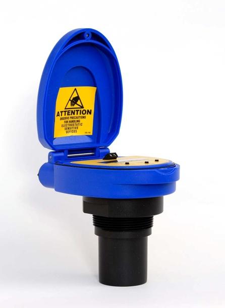
5 SAFETY PRECAUTIONS Step Three About this Manual: PLEASE READ THE ENTIRE MANUAL PRIOR TO INSTALLING OR USING THIS PRODUCT. This manual includes information on the LVU2800 Series Ultrasonic Level Switch from OMEGA ENGINEERING. Please refer to the part number located on the switch label to verify the exact model configuration, which you have purchased. User s Responsibility for Safety: OMEGA ENGINEERING manufactures a broad range of level sensing technologies. While each of these sensors is designed to operate in a wide variety of applications, it is the user s responsibility to select a sensor model that is appropriate for the application, install it properly, perform tests of the installed system, and maintain all components. The failure to do so could result in property damage or serious injury. Proper Installation and Handling: Only professional staff should install and/or repair this product. Install the switch with the included FKM gasket and never over tighten the switch within the fitting. Always check for leaks prior to system start up. Wiring and Electrical: A supply voltage of 12 to 28 VDC is used to power the LVU2800 Series. Electrical wiring of the transmitter should be performed in accordance with all applicable national, state, and local codes. Material Compatibility: The enclosure is made of Polycarbonate (PC). The transducer is made of Polyvinylidene Fluoride (PVDF). Make sure that the model, which you have selected, is chemically compatible with the application media. Enclosure: While the switch housing is liquid resistant the LVU2800 Series is not designed to be operational when immersed. It should be mounted in such a way that the enclosure and transducer do not come into contact with the application media under normal operational conditions. The enclosure has a flip cover with dual 1/2 NPT female conduit ports and an internal terminal strip for wiring. To open the enclosure, you will need a small insertion tool such as a screwdriver. Loosen the locking screw located at the top front of the enclosure. Rotate the hinged cover up for 135 access to the faceplate and terminal strips. Before closing the enclosure, make sure that the enclosure gasket is properly seated, and that any conduit fittings, cable connectors or plugs are installed correctly and sealed. Handling Static Sensitive Circuits/Devices: When handling the transmitter, the technician should follow these guidelines to reduce any possible electrostatic charge build up on the technician s body and the electronic part. 1. Always touch a known good ground source before handling the part. This should be repeated while handling the part and more frequently after sitting down from a standing position, sliding across the seat or walking a distance. 2. Avoid touching electrical terminals of the part unless making connections. 3. DO NOT open the unit cover until it is time to calibrate. 5 of 23
6 SAFETY PRECAUTIONS Step Three Make a Fail Safe System: Design a fail safe system that accommodates the possibility of switch and/or power failure. OMEGA ENGINEERING recommends the use of redundant backup systems and alarms in addition to the primary system. Flammable, Explosive or Hazardous Applications: LVU2800 Series should not be used within classified hazardous environments. Warning: Always use the FKM gasket when installing the LVU2800 Series, and make sure that all electrical wiring of the switch is in accordance with applicable codes. Components: LVU2800 Series is offered in three different models. Depending on the model purchased, you may or may not have been shipped all the components shown below. You do however, need an LVU2800 Series and FKM gasket to configure, install and operate LVU2800 Series. LVU2800 Series o LVU (3 m) range, Type 4X encl., 1 NPT o LVU (5.5 m) range, Type 4X encl., 2 NPT o LVU (8 m) range, Type 4X encl., 2 NPT o LVU (10 m) range, Type 4X encl., 2 NPT FKM Gasket o Part # for LVU2810 series only o Part # for LVU2818, LVU2826 and LVU2832 series Quick Start Guide 6 of 23


7 WIRING Step Four Below is a quick review of wiring the LVU2800 Series to common display, controllers and PLC s. Proportional Level Controller LVCN 51 Series JWA mode (Factory Setting) Proportional Level Controller LVCN 51 Series JWB mode Generic Loop Powered Display Generic PLC 7 of 23

8 WIRING (continued) Step Four General notes for electrical connections, usage and safety: Where personal safety or significant property damage can occur due to a spill, the installation must have a redundant backup safety system installed. Wiring should always be completed by a licensed electrician. Supply voltage should never exceed 28 VDC. The sensor materials must be chemically compatible with the liquids to be measured. Design a fail safe system for possible sensor and/or power failure. Never use the sensor in environments classified as Hazardous. Voltage Output LVU2800 Series can be used as a 0 to 5 or 0 to 10 VDC output device. A resistor will need to be added to the circuit to enable a voltage output (refer to the wiring diagram below). 0 5 VDC output o Add a 250 Ohm resistor o Actual output will be 0.8 to 5 VDC 0 10 VDC output o Add a 500 Ohm resistor o Actual output will be 2 to 10 VDC 8 of 23
9 GETTING STARTED Step Five LVU2800 Series can be configured before installation. The switch features non volatile memory, so the set points configured before installation will not be lost when the switch is powered down. To start, all you need is the following information: Basic Tank Information: o HEIGHT Distance from the transducer face to the bottom of the tank. o FILL H Maximum fill height of the liquid from the bottom of the tank. o These values will all be in the same distance value (inches, centimeters, feet or meters) and will all be measured from the bottom of the tank. Power: o Provide 12 to 28 VDC input power to the LVU2800 Series. Feature Guide: FEATURE Easy to use MENU Many UNITS of measurement. No cumbersome measure required. Set point distances are relative to the tank bottom. Optional Target Calibration Fail Safety ACCESS BY Press and hold SELECT key until MENU is displayed approximately 5 seconds. The MENU items will rotate through display, press SELECT to change an item. In the MENU mode, press SELECT when UNITS is display, then select INCHES, CM (centimeter), FEET, METERS or PERCENT. In MENU mode, select the TANK item and set the HEIGHT of the tank from the transducer face to the bottom of the tank. Set the Fill Height (FILL H) to the maximum fill height of the liquid from the bottom of the tank. Now all of the set points are from the bottom of the tank up. Use this feature if the tank is at the empty or full setting. This will accept the current level as either empty (TG CAL EMPTY) of full (TG CAL FULL). Use the SAFE function to preset the output to either Empty (4 ma), Full (20 ma, 21 ma or 22 ma) or Hold Last Value in case the transmitter loses its signal (LOST). 9 of 23
10 GETTING STARTED (continued) Step Five Getting Around: LVU2800 Series is configured by the use of three push buttons (UP, DOWN and SELECT) and a LCD display. As a lockout feature, the buttons are inactive until the SELECT button is held down for 5 seconds, and then the display will begin to scroll through the top level of the configuration menu. Steps for Basic Configuration: 1. Select and Set the units of operation in the UNITS menu. 2. Configure the Sensor Height and Fill H under the TANK menu. 3. Set the SAFE value. Top Level The Configuration menu will continue to scroll through the items below until the SELECT button is pressed. UNITS TANK SAFE TG CAL VALUES HELP RUN. To return to the Operational mode of LVU2800 Series, press SELECT while RUN appears in the display. UNITS Allows end user to select the units for configuration and operation. Select between Inches, Centimeters, Feet, Meters or Percent. Press EXIT to return to the Top Level menu. TANK Allows the end user to configure the operational range for the switch. o HEIGHT Distance from the transducer face to the bottom of the tank. o FILL H Maximum fill height of the liquid from the bottom of the tank. o REV MA Allows the transmitter to reverse the current output such that 4 ma is at FULL and 20 ma is at EMPTY. o Press Exit to return to the Top level Menu. o Note: if UNITS is set to Percent, then TANK will not appear. To view TANK, set UNITS to any of the following: Inches, Centimeters, Feet or Meters. SAFE The fail safe for the LVU2800 Series can be preset to the customer s requirement. o 22 ma Overfill fail safe setting. o 21 ma Overfill fail safe setting. o 20 ma Full fail safe setting. o 4 ma Empty fail safe setting. o HOLD Keeps the output at its last current reading when fail safe condition occurs. TG CAL Target Calibration (allows for the sensor to accept the current level as either EMPTY or FULL. VALUES Provides setup information, the ability to reset the LVU2800 Series and a simulation mode to test the relay function. o SETUP Will display the setting for all functions of LVU2800 Series. o DIAG This is a production test feature used by the factory to confirm operation. This mode should only be used when supervised by an Omega Engineering representative. o RESET Will reset the LVU2800 Series back to its original factory setting. HELP Provides information for contacting Omega Engineering no line. RUN Returns the unit to normal measurement and control mode. 10 of 23
, FEET, METERS or PERCENT. 3.")

11 GETTING STARTED (continued) Step Five How to enter the MENU: 1. Press and hold SELECT key (approximately 5 seconds) until MENU is displayed. 2. The menu items will rotate through display. 3. Press SELECT to change an item. How to configure UNITS: 1. In the MENU mode, press select when UNITS is display. 2. Press SELECT to choose between INCHES, CM (centimeter), FEET, METERS or PERCENT. 3. Select EXIT to return to the Top Level Menu. Note: Reading the level of liquid in Percent: Omega Engineering recommends that when selecting PERCENT, configure the HEIGHT and FILL H settings before selecting PERCENT in order to span the LVU2800 Series for your application requirements. When in PERCENT, the operational span will be based upon the last TANK settings, typically the factory settings for HEIGHT and FILL H. LVU2800 Series HEIGHT FILL H LVU2810 Series (300 cm) (290 cm) LVU2818 Series (550 cm) (530 cm) LVU2826 Series (800 cm) (780 cm) LVU2832 Series (1000 cm) (970 cm) When PERCENT is selected, the TANK settings (HEIGHT and FILL H) will be disabled. 11 of 23
 or")


12 GETTING STARTED (continued) Step Five DISPLAY AIR Mode vs. LIQUID Mode: The display can be made to display either the height of liquid in the tank (LIQUID mode) or the amount of air in the tank (AIR mode). AIR mode Will display the distance from the bottom of the sensor to the surface of the liquid. LIQUID mode Will display the height of liquid measured from the bottom of the tank. How to change the display mode: 1. In the MENU mode, press select when UNITS is display. 2. Press SELECT when DISPLAY appears. 3. Press SELECT to choose between AIR or LIQUID. 4. When EXIT appears, press SELECT return to Top Level Menu. 12 of 23

 until SAVED is displayed. 5. When FILL H appears, press SELECT. 6.")

13 GETTING STARTED (continued) Step Five How to configure the Operational range of LVU2800 Series: No cumbersome measurement is required via Target Calibration to establish set points. Set point distances are relative to the tank bottom. 1. In MENU mode, select the TANK item. 2. When HEIGHT appears, press SELECT. 3. Using the UP and DOWN buttons, set the HEIGHT of the tank from the transducer face to the bottom of the tank. 4. To enter the value, press and hold SELECT (Approximately 2 seconds) until SAVED is displayed. 5. When FILL H appears, press SELECT. 6. Using the UP and DOWN buttons, set the Fill Height (FILL H) to the maximum fill height of the liquid from the bottom of the tank. 7. Press and hold SELECT (2 seconds) to enter the value. 8. When EXIT appears, press SELECT return to Top Level Menu. Sensor Height Fill Height Note: Omega Engineering recommends that when selecting PERCENT, configure the Height and Fill H settings before selecting PERCENT in order to span the LVU2800 Series for your application requirements. When PERCENT is selected, the TANK settings (Height and Fill H) will be disabled. 13 of 23

 with 20 ma at Empty and 4 ma at Full.")


14 GETTING STARTED (continued) Step Five How to set a Reverse the Current Output: The default for LVU2800 Series is to have 4 ma at Empty and 20 ma at Full. This is the normal (NORM) setting. The output can be reversed (REV) with 20 ma at Empty and 4 ma at Full. 1. In MENU mode, select the TANK item. 2. When REV MA appears, press SELECT. 3. When REV appears, press SELECT. 4. When EXIT appears, press SELECT return to Top Level Menu. LVU2800 Series is now in the Reverse mode. To switch back to the Normal mode, follow the instructions above and select NORM under step 3. How to set the SAFE setting: The default for Fail Safety (LOST) can be preset. The choices are 4 ma, 20 ma, 21 ma, 22 ma and HOLD. 1. In MENU mode, select the SAFE item. 2. When the required setting appears, press SELECT. 3. When EXIT appears, press SELECT return to Top Level Menu. 14 of 23

15 GETTING STARTED (continued) Step Five How to set using Target Calibration (Empty): Instead of measuring for Empty tank, the Empty distance can be set automatically. This method requires that the tank be Empty or at the level that is considered Empty in the application. To set TG Empty, follow the instructions below. 1. Before beginning, make sure the level is tank is at the Empty level. 2. In MENU mode, select the TG CAL item. 3. When EMPTY appears, press SELECT. This sets the current distance as the new Empty setting. 4. When EXIT appears, press SELECT return to Top Level Menu. How to set using Target Calibration (Full): Instead of measuring for Full tank, the Full distance can be set automatically. This method requires that the tank be Full or at the level that is considered Full in the application. To set TG Full, follow the instructions below. 1. Before beginning, make sure the level is tank is at the Full level. 2. In MENU mode, select the TG CAL item. 3. When FULL appears, press SELECT. This sets the current distance as the new Full setting. 4. When EXIT appears, press SELECT return to Top Level Menu. Note: When setting either the TG EMPTY or TG FULL, make sure the reflective surface is perpendicular to the LVU2800 Series and not at an angle. Be careful if the tank has a sloped or cone bottom and the bottom of the tank is exposed to air. 15 of 23

 x 1 thread reducer bushing. Mounting Guide 1. Do not mount at an angle 2.")


16 INSTALLATION Step Six The LVU2800 Series should always be mounted perpendicular to the liquid surface and installed using the provided FKM mounting gasket. Make sure that the fitting and transmitter threads are not damaged or worn. Always hand tighten the transmitter within the fitting. Perform an installed leak test under normal process conditions prior to system start up. Note: The preferred mounting fitting for the LVU2810 series is a plastic 2 thread (or slip) x 1 thread reducer bushing. Mounting Guide 1. Do not mount at an angle 2. Liquid should never enter the dead band 3. Side Wall: a. For LVU2810 Series mount at least 2 from the side wall b. For LVU2818, LVU2826 & LVU2832 Series mount at least 3 from the side wall 4. Do not mount where obstacles will intrude on sensor s beam width a. See Specifications on page 3 5. Do not mount in a vacuum 6. Avoid mounting in the center of a dome top tank. 7. In cone bottom tank, position the sensor over the deepest part of the tank. Do not install at angle relative to the liquid. Do not install within 3 of tank sidewall. Do not install with objects in the beam. Do not install in applications with vacuum. Installation in existing fittings If the existing fitting is larger than the threads of the LVU2800 Series, select a reducer bushing such as a 2 thread x 1 thread, a 2 slip x 1 thread, 3 thread x 2 thread or 3 slip x 2 thread. Metal Tanks (LVU2810 series only) Omega Engineering ultrasonic transmitters have been optimized for use in non metallic fittings. 1. For best performance, avoid the use of metallic fittings. a. Use a plastic 2 x 1 reducer bushing, or a plastic 1 flange (See Fitting Selection on next page). 2. While installations directly into a 1 metal fitting are not recommended, acceptable results may be obtained if the 1 fitting is a half coupling in form and the outer diameter of the coupling is tightly wrapped in vinyl tape to dampen vibrations. 16 of 23

 styles and/or pipe stops forward of the installed transducer. c. Always mount the tank adapter so the majority of fitting is outside the tank. i. Never mount the tank adapter upside down or the bulk of the material is inside the tank.")
 diameter risers should be no taller than 5 (12.7 cm).")
17 INSTALLATION (continued) Step Six Fitting Selection: Check the part number to determine the required fitting mount size and thread type. LVU2800 Series is commonly installed in tank adapters, flanges, brackets or standpipes. Note: Always include the gasket when installing the LVU2800 Series. 1. Tank Adapter: Select a tank adapter fitting, such as a 1 adapter for the LVU2810 series or a 2 adapter for the LVU2818, LVU2826 & LVU2832 series. a. For best results, select a 2 tank adapter and add a 2 x 1 reducer bushing. b. Avoid tank adapter (thread x thread) styles and/or pipe stops forward of the installed transducer. c. Always mount the tank adapter so the majority of fitting is outside the tank. i. Never mount the tank adapter upside down or the bulk of the material is inside the tank. 2 Tank Adapter Socket x Thread Tank Adapter w/ 2 x1 Reducer Bushing Tank Adapter Thread x Thread Do not use thread x thread 2. Riser: Installations with tall, narrow risers can impede the acoustic signal. a. LVU2818, LVU2826 & LVU2832 Series: 2 (5 cm) diameter risers should be no taller than 5 (12.7 cm). Larger diameter risers should be no taller than 12 (30.5 cm). b. LVU2810 Series: Note: Do not exceed the dimensions listed above 17 of 23
. c.")
18 INSTALLATION (continued) Step Six 3. Flange (LVU2810 series): If installing on a flange, select a flange with a thread that is above the plane of the flange. a. The LVU2818, LVU2826 & LVU2832 series works well with Flange installations. b. Avoid the use of blind flanges with tapped threads or flanges where the threads are even with the plane of the flange, such as the Banjo 1" Poly ANSI Flange (series AF100). c. Use a flange with a 2 thread and add a 2 to 1 reducer bushing to complete the installation. 2 Flange w/ thread out of plane 2 Flange w/ thread in plane 2 Flange w/ Reducer Bushing Do not use thread in plane 4. Side Mount Bracket: For installations in open tanks and sumps, use the LVM 30 series side mount bracket. a. For the LVU2810 series, order the LVM 30 with a 2 x 1 Reducer Bushing. b. For the LVU2818, LVU2826 & LVU2832, series, order the LVM 30 side mount bracket. 18 of 23

19 INSTALLATION (continued) Step Six 5. Stand Pipe: A standpipe maybe used to dampen turbulence or when foam is present in the application. a. Pipe can be made of any material. b. Select a minimum 3 ID pipe for the stand pipe. i. A 2 pipe is usable with the LVU2810 series, but is the minimum. ii. Pipes larger than 3 can also be used. c. Use a coupling and reducer bushing to attach the LVU2800 Series to the pipe. i. With the LVU2810 series, be sure to use a plastic reducing bushing 2 Thread x 1 Thread fitting or 2 Slip x 1 Thread fitting. d. The pipe length should run the measurement span and the bottom of the pipe should remain submerged at all times to prevent foam from entering the pipe. e. Cut a 45 notch at the bottom of the pipe and drill a 1/4 pressure equalization hole in the dead band. f. The pumps should not drive liquid past the open end of the stand pipe which causes the liquid in the pipe to oscillate. 19 of 23
20 APPENDIX Step Seven Setup: You can view how the LVU2800 Series is configured. 1. From the main MENU level, press SETUP when VALUES appears. 2. When SETUP appears, press the SELECT key. 3. Setup will display the following information: a. Units, Display, Rev ma, Safe, Height, Fill H 4. When completed, press SELECT when EXIT appears to return to the main program level. Diagnostics (DIAG) Parameters: This mode runs diagnostic tests that confirm operation of LVU2800 Series. This mode should only be used when supervised by an Omega Engineering representative. Reset: LVU2800 Series enables the end user to reset the entire configuration back to the original factory settings. Follow the instructions below to reset LVU2800 Series: 1. From the main MENU level, press SELECT when VALUES appears. 2. When RESET appears, press the SELECT key. 3. When YES appears, press SELECT key to reset LVU2800 Series. a. To cancel the reset, press SELECT when NO appears. 4. When completed, press SELECT when EXIT appears to return to the main program level. Factory Settings: LVU2800 Series HEIGHT FILL H LVU2810 Series (300 cm) (290 cm) LVU2818 Series (550 cm) (530 cm) LVU2826 Series (800 cm) (780 cm) LVU2832 Series (1000 cm) (970 cm) User Settings: Fill out the chart below and keep as a record of your configuration. Tank Height = Fill-H = Norm Reverse Units Inches Feet cm Meter Percent Air Liquid Safe 22mA 21 ma 20mA Hold Last 4mA 20 of 23
21 APPENDIX Step Seven Troubleshooting: PROBLEM TANK does not appear on the main menu: Display shows FULL: Display shows EMPTY: Display shows WARMUP: Display shows LOST: Display is opposite of the measured value: Transmitter indicates a current of 0 ma: Transmitter jumps to a current reading between 19 and 20 ma: Transmitter indicates a current over 23 ma: SOLUTION Units function is set for PERCENT on LVU2800 Series: When Units is set for PERCENT, the TANK function is disabled. To re enable TANK, change units to INCHES, CM, FEET or METERS. Level of liquid is above the FILL H setting: Check the FILL H setting, making sure the FILL H setting is high enough so the level of liquid is below the FILL H setting. The Fill H setting is the distance from the bottom of the tank to the Full level of liquid. Level of liquid is beyond the HEIGHT setting: Check the HEIGHT setting, making sure the HEIGHT setting is low enough so the level of liquid is above the HEIGHT setting. Typically occurs when power is being applied to transmitter. Indicates a weak power supply, bad wire connections or the sensor is out of the operational range. Sensor is in a Fail Safe state. The return sound pulses are not reaching the transducer. First, cycle power off and on, waiting 5 seconds between the off and on states. If problem persists, check the installation fitting against the Installation instructions in the manual. Check the DISPLAY setting. AIR mode indicates the distance from the liquid to the sensor. LIQUID mode indicates the height of liquid in the tank. Change the DISPLAY mode from AIR to LIQUID or vice versa to correct. Check the wiring for an open circuit. An open circuit is the most common issue with a 0 ma signal. Check the installation of the transmitter. Bad installation fittings will cause false signals near the top of the tank, which typically translates to a signal between 19 and 20 ma. Also look for interference just below the transmitter. If the transmitter is installed in a metal fitting, switch to a plastic fitting. Immediately check the wiring for a short circuit. The LVU2800 Series is current limited to 22 ma. Anything above 23 ma indicates a short circuit. 21 of 23


22 22 of 23


23 23 of 23 M 5127/0312
EchoSwitch. LU74, LU77 & LU78 Series Manual NEMA 4X Enclosure. Ultrasonic Level Switch and Transmitter
 EchoSwitch Ultrasonic Level Switch and Transmitter LU74, LU77 & LU78 Series Manual NEMA 4X Enclosure Flowline, Inc. 10500 Humbolt Street, Los Alamitos, CA 90720 p 562.598.3015 f 562.431.8507 w flowline.com
EchoSwitch Ultrasonic Level Switch and Transmitter LU74, LU77 & LU78 Series Manual
 EchoSwitch Ultrasonic Level Switch and Transmitter LU74, LU77 & LU78 Series Manual Flowline Inc. 10500 Humbolt Street Los Alamitos, CA 90720 Tel: (562) 598 3015 Fax: (562) 431 8507 www.flowline.com Rev
BUBBLER CONTROL SYSTEM
 BUBBLER CONTROL SYSTEM Description: The HDBCS is a fully automatic bubbler system, which does liquid level measurements in water and wastewater applications. It is a dual air compressor system with, air
DeltaSpan Pressure Transmitters LD10 Series Owner s Manual
 Warranty, Service & Repair To register your product with the manufacturer, fill out the enclosed warranty card and return it immediately to: Flowline Inc. 10500 Humbolt Street Los Alamitos, CA 90720. If
300C/ 800C/ 990C Plus Series
 Ultrasonic Level Meter 300C/ 800C/ 990C Plus Series INSTRUCTION MANUAL (July, 2008) 1 SLM300C/ 800C/ 990C Plus Series July, 2008 Copyright IS Technologies Co., Ltd. All rights reserved. No part of this
DTG - LCD Digital Temperature Gauge USER MANUAL
 DTG - LCD USER MANUAL Page 1 of 7 USERS GUIDE page 1. Description 3 2. Function 3 3. Safety Instruction 3 3.1. Safety Conventions 3 3.2. Proper Use 3 4. Installation 4 4.1. Unpacking 4 4.2. Storage 4 4.3.
LS-UT Ultrasonic Level Transmitter
 Four Elms Road Edenbridge Kent TN8 6AB UK Features & Benefits Maintenance free Simple set-up procedure IP86 housing (2m for 24 hours) Low consumption Locking nut supplied Technical Overview The LS-UL ultrasonic
Installation, operating and maintenance Instructions for Seemag bypass level indicator
 Issue: S Date: 05-09-14 Type G35 General information The Seetru bypass magnetic level indicator, abbreviate SEEMAG, serves to show the filling level of fluids in tanks, basins, tubes etc. The Seemag operates
SPECIFICATIONS ATTENTION
 VPS 504 S06 Installation Manual - P/N 80122 - Ed. 01/09 VPS 504 S06 and S05 Valve Proving System Installation Instructions VPS 1 6 Gases Natural gas, air and other inert gases. NOT suitable for butane
BUBBLER CONTROL SYSTEM
 BUBBLER CONTROL SYSTEM Description: The LDBCS is a fully automatic bubbler system, which does liquid level measurements in water and wastewater applications. It is a dual air compressor system with, air
RC 195 Receiver-Controller
 Document No. 129-082 RC 195 Receiver-Controller Product Description The POWERS RC 195 Receiver-Controller is a pneumatic instrument that receives one, two or three pneumatic inputs. It produces a pneumatic
Electro Controls. Level WattsIndustries.co.uk
 Electro Controls Level - 2017 WattsIndustries.co.uk levels Section 19 LIQUID LEVEL SWITCHES HORIZONTAL ELL.. Volt free contacts To monitor liquid level in tanks and switch pumps or an alarm in the event
UBEC 1AT. AUTO TANK Fill System Installation, Operation, & Setup Instructions
 Document Number: XE-ATA5PM-R1A UBEC 1AT AUTO TANK Fill System 08899155 Installation, Operation, & Setup Instructions Rev170906-EB-FRC PHYSICAL: 1302 WEST BEARDSLEY AVE ELKHART, IN 46514 WWW.ELKHARTBRASS.COM
ACV-10 Automatic Control Valve
 ACV-10 Automatic Control Valve Installation, Operation & Maintenance General: The Archer Instruments ACV-10 is a precision automatic feed rate control valve for use in vacuum systems feeding Chlorine,
Ultrasonic level transmitter and indicator
 Ultrasonic level transmitter and indicator No contact with the product Compact design with polycarbonate housing (electronics and display). Remote display available on request Very good resistance in corrosive
PROPORTIONING VALVE. Model 150 INSTRUCTION MANUAL. March 2017 IMS Company Stafford Road
 PROPORTIONING VALVE Model 150 INSTRUCTION MANUAL March 2017 IMS Company 10373 Stafford Road Telephone: (440) 543-1615 Fax: (440) 543-1069 Email: sales@imscompany.com 1 Introduction IMS Company reserves
RAM Operation Manual. Worldwide Manufacturer of Gas Detection Solutions
 RAM 4021 Operation Manual Worldwide Manufacturer of Gas Detection Solutions TABLE OF CONTENTS RAM 4021 For Your Safety... 2 Description.... 2 Setup Mode.... 2 Lights/Alarms.... 3 Operation.... 4 Calibration....
3.0 Pressure Transmitter Selection
 3.0 Pressure Transmitter Selection Each Tronic Line pressure transmitter has different features to meet specific performance, environmental, and price requirements. It is not possible to describe every
Preferred Instruments Danbury, CT USA
 Tank Level Sensor Model TG-EL-WF-xx Installation & Operation Instructions SDI-TG-EL-WF March 6, 2006 Preferred Instruments Danbury, CT USA www.preferredinstruments.com CONTENTS Installation Pg. 2 Calibration
RAM 4021-PR. Operation Manual. Worldwide Manufacturer of Gas Detection Solutions
 RAM 4021-PR Operation Manual Worldwide Manufacturer of Gas Detection Solutions TABLE OF CONTENTS RAM 4021-PR For Your Safety... 2 Description.... 2 Setup Mode.... 2 Lights/Alarms.... 3 Operation.... 4
Model 130M Pneumatic Controller
 Instruction MI 017-450 May 1978 Model 130M Pneumatic Controller Installation and Operation Manual Control Unit Controller Model 130M Controller is a pneumatic, shelf-mounted instrument with a separate
Installation, Operation and Maintenance Instructions for Electronically Controlled Pressurisation Units
 Installation, Operation and Maintenance Instructions for Electronically Controlled Pressurisation Units Models: EPS Single Pump EPT Twin Pump EPS-HP EPT-HP Single Pump High Pressure Twin Pump High Pressure
Aquavar SOLO 2 Frequently Asked Questions
 Aquavar SOLO 2 Frequently Asked Questions How do I size the Aquavar SOLO 2 for the appropriate pump/motor combination? Can I use a 208 Volt motor? Can I run the Aquavar SOLO 2 up to 80HZ? What are the
FTS SUBMERSIBLE PRESSURE TRANSMITTER USER S MANUAL
 FTS SUBMERSIBLE PRESSURE TRANSMITTER USER S MANUAL TABLE OF CONTENTS PRODUCT OVERVIEW 2 I - USE AND CARE: 3 II - INSTALLATION: 5 III - GENERAL MAINTENANCE TIPS: 5 IV - APPENDIX: A-1 2-WIRE CURRENT LOOP
OC Panel High Limit Aquastat Kit, Manual Reset p/n
 OC Panel High Limit Aquastat Kit, Manual Reset p/n 233202 Instruction Sheet APPLICATION The OC (Option Control) Panel High Limit Aquastat Kit provides electronic temperature sensing in a UL limit-rated
Pressure Dump Valve Service Kit for Series 2300 Units
 Instruction Sheet Pressure Dump Valve Service Kit for Series 00 Units. Overview The Nordson pressure dump valve is used to relieve hydraulic pressure instantly in Series 00 applicator tanks when the unit
Product Manual. Cyl-Tel and Tank-Tel Liquid Level Gauges. Designed and Built by: Chart Inc th Street NW New Prague, MN USA (800)
") Product Manual Cyl-Tel and Tank-Tel Liquid Level Gauges Designed and Built by: Chart Inc. 407 7th Street NW New Prague, MN 56071 USA (800) 400-4683 Part Number 20544482 Rev. C 2016 Chart Inc. Product
Product Manual Cyl-Tel and Tank-Tel Liquid Level Gauges Designed and Built by: Chart Inc. 407 7th Street NW New Prague, MN 56071 USA (800) 400-4683 Part Number 20544482 Rev. C 2016 Chart Inc. Product
Troubleshooting Guide: 640 Pediatric Exam Table with Midmark Scale
 Troubleshooting Guide: 640 Pediatric Exam Table with Midmark Scale Contents Description Refer To: Scale Troubleshooting Chart Troubleshooting Error Codes Error Messages Adjustments / Repair Procedures
Alphasense 4-20 ma transmitters offer convenience and easy maintenance for toxic sensors:
 ALPHASENSE USER MANUAL Page 1 4-20mA Transmitter for Toxic Sensors UMTOX-1 Issue 4 1 INTRODUCTION The Transmitter PCB includes circuitry for a three electrode toxic sensor to convert the µa output signal
TANK MANAGER FOR TWO TANKS OPERATING MANUAL. 10/31/11 C-More T6C L color touch panel
 TANK MANAGER FOR TWO TANKS OPERATING MANUAL 10/31/11 C-More T6C L color touch panel 1 TABLE OF CONTENTS GENERAL...3 INSTALLATION...4 STONE TEST PROCEDURE...7 OPERATIONAL SUMMARY...7 AUTO CARBONATION...10
MOYNO FLUID DETECTION CONTROL SERVICE MANUAL. Section: ACCESSORIES. Page: 1 of 8 Date: May 1, 1998 GENERAL
 MOYNO Section: ACCESSORIES Page: 1 of 8 Date: May 1, 1998 SERVICE MANUAL FLUID DETECTION CONTROL GENERAL The Moyno Fluid Detection Control prevents unnecessary loss of production time or repair costs to
Level transmitters and indicators Series LU Ultrasonic level transmitter and indicator for liquids and solids
 Level transmitters and indicators Series LU Ultrasonic level transmitter and indicator for liquids and solids No contact with the product Compact design with polycarbonate housing (electronics and display).
Sondaloop and MiniSonda Version 2 Ultrasonic Level Transmitter
 Sondaloop and MiniSonda Version 2 Ultrasonic Level Transmitter Installation & Setting up Instructions Hawker Electronics Limited O&M 82 57 The Avenue Issue H Rubery Industrial Estate APR 2017 Birmingham
The Ins and Outs of I/P Transducers
 The Ins and Outs of I/P Transducers By Mark B. Levine, ControlAir Inc. General description I/P transducers are versatile instruments that use an electrical control signal to proportionally regulate gas
L 100. Bubble-Tube Level System. Installation, Operation and Maintenance Instructions
 L 100 Bubble-Tube Level System Installation, Operation and Maintenance Instructions Figure 1 Contents Section Description Page 1.0 Introduction 2 2.0 Specifications 3 3.0 Installation 3 4.0 Warranty 6
RAI-M series RUDDER ANGLE INDICATOR SYSTEM
 RUDDER ANGLE INDICATOR SYSTEM RAI-M series SEAFIRST ENGINEERING CO 45-16, Ga Um Dong, Chang Won, Kyong Nam Korea Tel : 82 55 267 1645 Fax ; 82 55 266 1646 http://www.seafirst.co.kr GENERAL Seafirst Rudder
GV Standard X-Vent. Setup, Commissioning & Installation Guide
 GV Standard X-Vent Setup, Commissioning & Installation Guide Technical experts in the design, manufacture and supply of precision engineered, architectural rooflights for residential and commercial buildings.
RAM Operation Manual. Worldwide Manufacturer of Gas Detection Solutions
 RAM 4021 Operation Manual Worldwide Manufacturer of Gas Detection Solutions TABLE OF CONTENTS RAM 4021 For Your Safety... 2 Description.... 2 Setup Mode.... 2 Lights/Alarms.... 3 Operation.... 4 Calibration....
OEM Manual MODEL 2305 ECONOMICAL DIGITAL SINGLE CYLINDER SCALE
 OEM Manual MODEL 2305 ECONOMICAL DIGITAL SINGLE CYLINDER SCALE 1 These instructions generally describe the installation, operation, and maintenance of subject equipment. The manufacturer reserves the right
Features. Description
 Features Fast response flow meter ideal for inert gas and liquid mass flow measurement applications Smart electronics permit field adjustment of critical flow meter settings Field validation of flow meter
2600T Series Pressure Transmitter Models 264DC Differential and 264HC Gage Level Transmitters. Kent-Taylor
 INDUSTRIAL INSTRUMENTS AND CONTROLS SPECIALIST Kent-Taylor 2600T Series Pressure Transmitter Models 264DC Differential and 264HC Gage Level Transmitters Features Include Base accuracy : ±0.075% Span limits
Royce Interface Level Analyzer and Sensors
 Royce Interface Level Analyzer and Sensors Model 2511A Interface Level Analyzer The Model 2511A is capable of having the ultrasonic speed of sound signal from its transducers changed by the user in applications
Installation and Operation Manual
 Installation and Operation Manual WIKA FLR-SBDF / BLR-SBDF Magnetic Level Transmitter (Please retain for future usage) Contact: Gayesco-WIKA USA, L.P. 229 Beltway Green Boulevard Pasadena, TX 77503 www.wika.com
Stand-Alone Bubble Detection System
 Instruction Sheet P/N Stand-Alone Bubble Detection System 1. Introduction The Bubble Detection system is designed to detect air-bubble induced gaps in a bead of material as it is being dispensed. When
Float Operated Level Controllers
 CONTENTS Float Operated Level Controllers IM0015 Nov. 2014 PAGE Introduction 1 Scope 1 Description 1 Specification 1 Control Installation 2 INTRODUCTION Side Mount Back Mount Prior to installing, the instructions
Autocalibration Systems For In Situ Oxygen Analyzers
 Product Data Sheet PDS 106-340AC SPS 4000, IMPS 4000, and MPS 3000 January, 1999 Autocalibration Systems For In Situ Oxygen Analyzers Cost-effective autocalibration systems for installations ranging from
Operation manual Level sensor DC-LS-50 Operation Manual Level Sensor DC-LS-50
 Operation Manual Level Sensor DC-LS-50 Rev.02 (2014.06) OL Page 1 of 8 Table of contents I. STRUCTURE OF THE MANUAL / CLARIFICATION... 3 II. SAFETY AND HEALTH CONCERNS... 4 1 INTRODUCTION... 5 1.1 Use
Installation and Operation Manual
 Manual Static pressure transducer with controller Differential static pressure transducer with analog output and optional PI control mode Large diaphragm element with differential transformer Transducer
PX3005. Rangeable Industrial Pressure Transmitter M-5721/1018
 PX3005 Rangeable Industrial Pressure Transmitter INTRUCTION HEET -5721/1018 hop online at omega.com e-mail: info@omega.com For latest product manuals: omegamanual.info ! Pressure / differential pressure
250C-IG COMPRESSOR KIT 12V PART NO C-IG COMPRESSOR KIT 24V PART NO
 250C-IG COMPRESSOR KIT 12V PART NO. 25050 250C-IG COMPRESSOR KIT 24V PART NO. 25058 IMPORTANT: It is essential that you and any other operator of this product read and understand the contents of this manual
QBS Electronic Pressure Regulator
 INSTALLATION AND MAINTENANCE INSTRUCTIONS DESCRIPTION / IDENTIFICATION The QBS stainless steel series is an electronically controlled pressure regulator. The QBS controls the pressure on its output port
250C-IG COMPRESSOR KIT 12V PART NO C-IG COMPRESSOR KIT 24V PART NO
 250C-IG COMPRESSOR KIT 12V PART NO. 25050 250C-IG COMPRESSOR KIT 24V PART NO. 25058 IMPORTANT: It is essential that you and any other operator of this product read and understand the contents of this manual
Installation, Operation and Maintenance Instructions for Electronically Controlled Pressurisation Units Digital Range
 Installation, Operation and Maintenance Instructions for Electronically Controlled Pressurisation Units Digital Range Models: DS 126 Single Pump / Single System DT 126 Twin Pump / Single System DS 160
How to specify a product. Process Sensors and Mechanical Instruments
 How to specify a product Process Sensors and Mechanical Instruments Keep the overview. Here is some guideline information on how to specify our products. Intended as supplementary help to specification
Design Features. General Description
 Model thermal Mass Flow Controllers are designed to indicate and control set flow rates of gases. The combines the characteristics and accuracy of conventional mass flow devices into a unique compact design
Locator Locator-D-Lux Air-Saver G1 Air-Saver G2
 170663_air_saving_products 17-02-2011 16:42 Pagina 1 Locator Locator-D-Lux Air-Saver G1 Air-Saver G2 AIR SAVING PRODUCTS 170663_air_saving_products 17-02-2011 16:42 Pagina 2 170663_air_saving_products
P9000 DESCRIPTION. For parts requiring RoHS compliance, please contact factory. P February /6
 P9000 High accuracy through digital compensation High thermal stability Rugged stainless steel construction Ideal for test stands High burst pressure limit DESCRIPTION The P9000 Series is a range of advanced,
Exercise 5-2. Bubblers EXERCISE OBJECTIVE DISCUSSION OUTLINE. Bubblers DISCUSSION. Learn to measure the level in a vessel using a bubbler.
 Exercise 5-2 Bubblers EXERCISE OBJECTIVE Learn to measure the level in a vessel using a bubbler. DISCUSSION OUTLINE The Discussion of this exercise covers the following points: Bubblers How to measure
100C Air Compressor Kit
 10010 100C Air Compressor (standard mounting bracket, CE Spec) 10014 100C Air Compressor (no leader hose or check valve, CE Spec) 10016 100C Air Compressor (with Omega Bracket, CE Spec) IMPORTANT: It is
COMPRESSED AIR SAVING PRODUCTS INDEX. Useful information AIR-SAVER G1 AIR-SAVER G2 LOCATOR. Condensate Management Specialist
 INDEX Useful information AIR-SAVER G1 AIR-SAVER G2 LOCATOR COMPRESSED AIR SAVING PRODUCTS Condensate Management Specialist Information provided herewith is believed to be accurate and reliable. However,
GAS FUEL VALVE FORM AGV5 OM 8-03
 ALTRONIC AGV5 OPERATING MANUAL GAS FUEL VALVE FORM AGV5 OM 8-03 WARNING: DEVIATION FROM THESE INSTALLATION INSTRUCTIONS MAY LEAD TO IMPROPER ENGINE OPERATION WHICH COULD CAUSE PERSONAL INJURY TO OPERATORS
700 SERIES BMS II BUBBLER MONITORING SYSTEM
 1 700 SERIES BMS II BUBBLER MONITORING SYSTEM VISIT OUR WEBSITE AT SIGMACONTROLS.COM 700 SERIES BMS II MANUAL 062114 2 TABLE OF CONTENTS INTRODUCTION 3 Physical Specifications WIRING 5 PROGRAMMING & SETUP..
North American Pressure Switches
 Combustion North American Pressure Switches Bulletin 8757 Pressure switches are used with Automatic Shutoff Valves or Solenoid Valves to interrupt fuel flow in the event of fuel or air failure. They are
RPS900W Redundant Power Supply. Installation Guide.
 RPS900W Redundant Power Supply Installation Guide www.edge-core.com Installation Guide RPS900W Redundant Power Supply Single DC Output Port with Dual Output Voltages RPS900W E10013-CS-R01 1500000081A
Universal Valve Company Inc
 Universal Valve Company Inc 800-223-0741 www.universalvalve.com 1975-FA34 (Air Tower Troubleshooting Manual) Overview This manual has been arranged as a tool for diagnosing, and repairing Free Air Universal
444C DUAL PERFORMANCE VALUE PACK
 (Chrome) PART NO. 44432 IMPORTANT: It is essential that you and any other operator of this product read and understand the contents of this manual before installing and using this product. SAVE THIS MANUAL
BAPI Pressure Line of Products - FAQs
 Table of Contents 1. Several manufacturers produce pressure transmitters, why should I purchase from BAPI?... p. 2 2. BAPI makes several styles of pressure transmitters. What are the features of each?...
200 PSI COMPRESSORS - MODEL NUMBERS
 200 PSI COMPRESSORS - MODEL NUMBERS 380C AIR COMPRESSOR KIT PART NO. 38033 480C AIR COMPRESSOR KIT PART NO. 48043 380C 480C IMPORTANT: It is essential that you and any other operator of this product read
4150K and 4160K Series Wizard II Pressure Controllers and Transmitters
 Instruction Manual Form 5177 March 1999 4150K and 4160K Series 4150K and 4160K Series Wizard II Pressure Controllers and Transmitters Contents Introduction.............................. 2 Scope of Manual.............................
200 PSI FAST-FILL AIR SOURCE KIT
 200 PSI FAST-FILL AIR SOURCE KIT 55% Duty Compressor on 2.0 Gallon Air Tank PART NO. 20007 IMPORTANT: It is essential that you and any other operator of this product read and understand the contents of
RAM Operation Manual
 RAM 4021-1 Operation Manual Worldwide Manufacturer of Gas Detection Solutions TABLE OF CONTENTS RAM 4021-1 For Your Safety... 2 Description... 2 Setup Mode... 3 Lights/Alarms... 3 Operation... 4 Calibration...
TECHNICAL DATA MAINTENANCE AIR COMPRESSOR MODEL G-1
 Dry 131h 1. DESCRIPTION The Viking Model G-1 Maintenance Air Compressor is an electric motor-driven, aircooled, single-stage, oil-less compressor. The unit is equipped with a check valve and provides a
10 switches simultaneously. The settings of the master sensor (source of copy) can be copied to the slave sensors. Reducing setting labor
 can be copied to the slave sensors. Reducing setting labor") 2-Color Display High-Precision Digital Pressure Switch Series ZSEA(F)/EA ZSE E RoHS New IP65 ZSE E ZSE0 E0 M8 connector type E70 ZSE E E Applicable Air, Non-corrosive gas, Non-flammable gas fluid Can copy
2-Color Display High-Precision Digital Pressure Switch Series ZSEA(F)/EA ZSE E RoHS New IP65 ZSE E ZSE0 E0 M8 connector type E70 ZSE E E Applicable Air, Non-corrosive gas, Non-flammable gas fluid Can copy
IMPORTANT SAFETY INSTRUCTIONS
 IMPORTANT SAFETY INSTRUCTIONS CAUTION - To reduce risk of electrical shock: - Do not disassemble. Do not attempt repairs or modifications. Refer to qualified service agencies for all service and repairs.
420C AIR COMPRESSOR KIT PART NO C AIR COMPRESSOR KIT PART NO
 420C AIR COMPRESSOR KIT PART NO. 42042 460C AIR COMPRESSOR KIT PART NO. 46043 420C 460C IMPORTANT: It is essential that you and any other operator of this product read and understand the contents of this
400C & 450C DUAL PERFORMANCE VALUE PACKS
 (Chrome) PART NO. 40013 (Silver) PART NO. 45012 (Chrome) PART NO. 45013 IMPORTANT: It is essential that you and any other operator of this product read and understand the contents of this manual before
Simple Set. Pressure Independent Control Valves 2 Way 1/2-2
 The Bray Simple Set is a threaded pressure independent control (PIC) valve designed for a wide variety of hot water and chilled water control applications. The SS Series combines high rangeability control
PRESSURE SWITCHES Bulletin 8757
 PRESSURE SWITCHES Bulletin 8757 September 2013 Pressure switches are used with Automatic Shutoff Valves or solenoid valves to interrupt fuel fl ow in the event of fuel or air failure. They are also used
Model PSI Compressor with 3-Gallon Air Tank 12VDC
 Model 6350 150 PSI Compressor with 3-Gallon Air Tank 12VDC IMPORTANT: It is essential that you and any other operator of this product read and understandd the contents of this manual before installing
780S Ultra High Purity Series
 Smart Ultra High Purity Thermal Gas Mass Flow Meter Features Measures mass flow directly, no seperate temperature or pressure inputs required Field adjustment of critical flow meter settings via on-board
T i m i n g S y s t e m s. RACEAMERICA, Inc. P.O. Box 3469 Santa Clara, CA (408)
") RACEAMERICA T i m i n g S y s t e m s Demo Tree Controller Owner s Manual Models 3204D, 3204DW & 3204DX Rev D RACEAMERICA, Inc. P.O. Box 3469 Santa Clara, CA 95055-3469 (408) 988-6188 http://www.raceamerica.com
RACEAMERICA T i m i n g S y s t e m s Demo Tree Controller Owner s Manual Models 3204D, 3204DW & 3204DX Rev D RACEAMERICA, Inc. P.O. Box 3469 Santa Clara, CA 95055-3469 (408) 988-6188 http://www.raceamerica.com
OSAT Series. Intrinsically Safe Infrared Temperature Sensor Operator's Guide
 OSAT Series Intrinsically Safe Infrared Temperature Sensor Operator's Guide Issue L Jan 2017 Introduction OSAT Series intrinsically safe non-contact infrared temperature sensors measure the temperature
Pressure Measurement Single-range transmitters for general applications
 Siemens A 207 Overview Application The SITRANS P Compact pressure transmitter is designed for the special requirements of the food, pharmaceutical and biotechnology industries. The use of high-grade materials
Installing a Probe. Typical Installation
 for hazardous locations. Prior to any installation in a Classified Hazardous Location, verify installation methods by the Control Drawing referenced on the product s name tag 2. The Feed Through Assemblies
Instruction Manual. PLT Series. 1. General Specification. 2. Installation. 3. Wiring. 4. Function. 5. Setting & Calibration
 4 Digit Display, 4-20mA Output Instruction Manual (Digital Differential Pressure Transmitter) 1. General Specification 2. Installation 3. Wiring 4. Function 5. Setting & Calibration 1 4 20 1 Differential
Section 3- Repair and Calibration Procedures
 Section 3- Repair and Calibration Procedures 1. Refrigerant Removal Procedures 2. Scale/PC Board Recalibration Procedure 3. PC Board Configuration Procedure of AR400 4. Scale Tare Procedure 5. Gauge Calibration
DeltaSpan General Purpose Water Small Bore or Wastewater Pressure Level Transmitter LD34 and LD35 Series Manual
 DeltaSpan General Purpose Water Small Bore or Wastewater Pressure Level Transmitter LD34 and LD35 Series Manual LD34 Series Shown LD35 Series Shown Flowline, Inc. 10500 Humbolt Street Los Alamitos, CA
Sterisil Ac+ Installation & Operating Manual
 Sterisil Ac+ Installation & Operating Manual 719 622 7200 Sterisil.com Arbor Dental Associates 2 Table of Contents Introduction 4 Sterisil Ac + Features 5 Installation Instructions 6 Maintenance 10 Troubleshooting
36E DSI, HSI & Proven Pilot Two-Stage Combination Gas Valve INSTALLATION INSTRUCTIONS
 INLET PRESS TAP WTE-RODGERS 36E96-314 DSI, HSI & Proven Pilot Two-Stage Combination Gas Valve INSTALLATION INSTRUCTIONS Operator: Save these instructions for future use! FAILURE TO READ AND FOLLOW ALL
Echotel Model 3P1 Pump Controller and Ultrasonic Level Transmitter
 Echotel Model 3P1 Pump Controller and Ultrasonic Level Transmitter D E S C R I P T I O N The Echotel Model 3P1 Pump Controller is a full-featured non-contact ultrasonic system designed specifically to
Sensoric 4-20 ma Transmitter Board Operation Manual
 Sensoric 4-20 ma Transmitter Board Operation Manual 1 Content Features Operation Manual Technical Data Mechanical Dimensions Remarks & Contact information 2 Features Soldered sensor cell (non replaceable)
Inert Air (N2) Systems Manual
 Systems Manual") INSTRUCTION MANUAL Inert Air (N2) Systems Manual N2-MANUAL 2.10 READ AND UNDERSTAND THIS MANUAL PRIOR TO OPERATING OR SERVICING THIS PRODUCT. GENERAL INFORMATION Positive pressure nitrogen gas pressurizing
INSTRUCTION MANUAL Inert Air (N2) Systems Manual N2-MANUAL 2.10 READ AND UNDERSTAND THIS MANUAL PRIOR TO OPERATING OR SERVICING THIS PRODUCT. GENERAL INFORMATION Positive pressure nitrogen gas pressurizing
OEM Manual. MODEL ½ Digit DRUM SCALE
 OEM Manual MODEL 4020-3 ½ Digit DRUM SCALE Scaletron Industries, Ltd. Bedminster Industrial Park 53 Apple Tree Lane P.O. Box 365 Plumsteadville, PA 18949 USA Toll Free: 1-800-257-5911 (USA & Canada) Phone:
Pressure Dump Valve Service Kit for Series 3000 Units
 Instruction Sheet Pressure Dump Valve Service Kit for Series 000 Units. Overview The Nordson pressure dump valve is used to relieve hydraulic pressure instantly in Series 00, 400, 500, and 700 applicator
AMS 2710 PCB pressure sensor module with V output
 FEATURES Universal pressure sensor module with 0.. 10 V voltage output Fully calibrated and temperature compensated sensor module Variants for (bidirectional) differential, gage, absolute and barometric
Flow and Energy Measurement F-5400 THERMAL MASS FLOW METER
 THERMAL MASS FLOW METER s Series Thermal Mass Flow Meters provide accurate and reliable flow measurement for natural gas, compressed air, and other industrial gas applications. Natural Gas Compressed Air
RAM 4021-DPX Operation Manual
 RAM 4021-DPX Operation Manual Worldwide Manufacturer of Gas Detection Solutions TABLE OF CONTENTS ABL 4021-DPX / RAM 4021-DPX For Your Safety... 3 Description... 3 Setup Mode... 4 Lights/Alarms... 4 Operation...
CCT-7320/ROC-2313 Reverse Osmosis Controller
 CCT-7320/ROC-2313 Reverse Osmosis Controller 1 General The instrument is a combined control instrument of a reverse osmosis controller and an on-line conductivity instrument. It can perform the operation
Universal Valve Company Inc
 1975-FA34 (Air Tower Troubleshooting Manual) Overview This manual has been arranged as a tool for diagnosing, and repairing Universal Air Towers Please read closely to identify the components that are
HBLT-A1 LIQUID LEVEL SENSOR
 Instruction manual HBLT-A1 LIQUID LEVEL SENSOR for measuring liquid level in refrigerant vessels Instruction manual HBLT - A1 - Liquid level Transmitter (HBLT-A1-008-UK) 1 / 16 Contents Safety instructions...