University of Minnesota Nano Fabrication Center
|
|
|
- Randolph Atkins
- 6 years ago
- Views:
Transcription

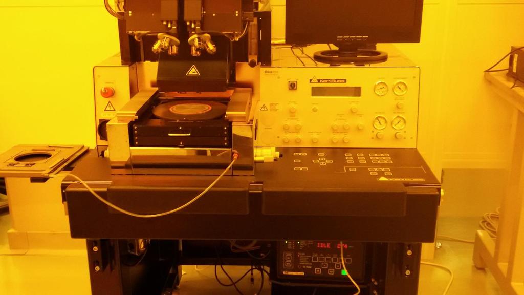
1 Equipment name: Karl Suss Mask Aligners Badger name: MA6-P Revision number: 0 Model: MA6 Revisionist: Paul Kimani Location: Bay 4 PAN Date: September 17, Introduction The Karl Suss MA6-PAN is a contact aligners used for optical lithography down to 1 micron. It can be used with 4-inch, 5-inch and 7-inch mask plates and is capable of processing pieces, 4 inch and 6 inch substrates. Wafers and substrates up to 6mm thickness can be processed. It is equipped with a 350 watt, UV 400 mercury arc lamp (350nm 450nm wavelength range) capable of operating in constant power or constant intensity mode. MNC operates its aligners in constant intensity mode, where the power to the lamps automatically adjusts to maintain a constant intensity. The MA6-PAN is ideal for exposing broadband positive and negative resists. The machine is used for front side alignment with Top Side Scopes 2. Description a. A 350 watt mercury arc lamp with smart power supply capable of operating in constant power mode or constant intensity mode. The lamp is run in constant intensity mode, whereby as the lamp ages, power is adjusted automatically to keep the intensity constant. b. Front-side alignment is achieved using top-side microscope, mask and wafer placed on their respective seats

2 c. Six lithographic modes for exposure. They include: SOFT CONTACT, HARD CONTACT, LOW VACUUM CONTACT, VACUUM CONTACT and PROXIMITY. d. 4-inch, 5-inch and 7-inch masks can be used in any of the aligners e. Three chuck sizes can be used with the aligners: piece chuck, 4-inch and 6-inch. f. Alignment can be done using one or two objectives. Positional memory lock allows one to fast scan between two locations quickly. g. Coordinate system: The length units for the x and y- direction are in mm. The z- direction length unit is in µm. The origin is in the center of the alignment stage unit. The origin in the z-direction is at the mask or upper substrate plane. h. LED on: Key selected or function active i. LED off: Key not selected or function deactivated j. LED flashing: Most applicable key to continue. 3. Safety a. Do not look directly at the ultraviolet light or its reflection. The aligners lamps output 365nm, 405nm and 436 nm wavelengths light. b. Beware of moving parts on the aligner. The microscope assembly moves up and down. The exposure tool will move forward when exposing a wafer. Be careful to avoid putting any body part, clothing, or other material in the path of the moving parts. 4. Restrictions/Requirements a. Do not place heavy or sharp objects on the touch panel b. Do not lean on the anti-vibration table c. Do not turn any knobs more than a few degrees at a time. Turn all knobs with care. Handle all equipment gently and with care. d. Do not use acetone to clean the chuck. If needed, use a cleanroom towel with some methanol or IPA. If you are having repetitive issues with wafer chuck vacuum, report the problem on Badger and/or contact staff. e. Any chucks not in use should be placed in the chucks cabinet for safe keeping f. When handling the mask plate, take care not to damage the proximity flags g. Enable the aligner on Badger before each use. 5. Required facilities a. Compressed air - 5 bar b. Vacuum (< -0.8 relative to ambient pressure or 0.2 bar absolute) c. Nitrogen gas 1bar d. Electrical power - 2 -

 for parallelism adjustment.")
3 6. Definitions a. Mask Holder - holds masks in place. Avoid tampering with the 3 metal proximity flags. b. Chuck - holds wafer in place c. WEC Wedge Error Compensation. It occurs after loading the substrate. In this procedure, the wafer is leveled so that it is as close as possible to being parallel to the mask. The WEC-pressure is used to compensate for the higher gravitation force of a bigger chuck. There are two WEC options; contact and proximity. Contact WEC achieves parallelism by utilizing the flatness of the mask/wafer contact. Proximity WEC uses three proximity flags (see a & m) for parallelism adjustment. Of these two, the contact WEC has less error and is preferred unless circumstances dictate otherwise. If you need to use proximity WEC, use only the MA6-P. If you experience regular over-current errors, reduce the WEC-pressure to 0 (zero). At 0 bar pressure, the force during WEC is about 7N - 8N. d. Micrometer knobs X- and Y- Located on left and the right side of the alignment stage respectively, they are used to move the microscope along the x- (maximal travel ± 10mm) and y-axis (maximal travel ± 5mm). e. Stage θ-movement Micrometer: This is a small knob at the right side of the alignment stage. Maximal travel is ± 5. f. Fast key when activated (LED is on), it allows the microscope to move rapidly in either the x- or y-axis g. SEP keys These keys enable the alignment position of the chuck to be changed in finite steps of 1µm along the z-axis. The keys are active with the wafer loaded and in alignment - 3 -
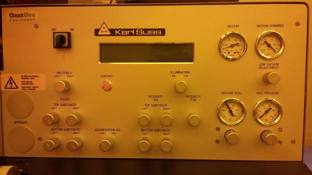
4 position. When used, they increase or decrease the alignment gap between the mask and the wafer. h. ALIGN CONT/EXP Key Enables the operator to change the position of the exposure chuck between alignment gap and contact position with the mask (or proximity if the selected exposure program is proximity). This places the wafer in contact position (proximity) without exposure. Pressing the key again returns the wafer back to its original alignment position. i. ALIGNMENT CHECK key This triggers all parameters of an exposure program except the exposure. The key only works for Hard Contact, Vacuum contact and Low Vacuum Contact. Using this key allows one to check their final alignment before pressing the exposure key. j. EXPOSURE Key After completing the alignment process, press this key to start exposure. k. TSA Key Top side alignment. The top microscope is used to align the mask to the top/front of the wafer. The topside of the substrate is then exposed. l. Multiple Exposure Key This key allows for the overall exposure to be broken down into equal shorter exposure intervals with defined wait times during which the substrate is not exposed. It may be useful in exposure of thick photoresists that have long exposure requirements. m. Proximity Flags The three pneumatically actuated flags located on the mask holder sides. They serve as spacers between the mask and substrate during proximity WEC. n. Overcurrent Error This error may occur when you press the exposure key. However, its cause emanates from bad WEC procedure that causes the motor which brings the mask and wafer into contact, to draw excessive current. The problem manifests itself when the exposure procedure is triggered. Often observed when using a standard mask and little substrate pieces placed off-center on a carrier wafer. 7. Exposure Programs a. Soft Contact One of the six possible lithography modes. The substrate is brought into contact with the mask by a preset force exerted by the WEC head, during exposure. This mode is suitable for feature sizes 2 µm or larger. b. Hard Contact Similar to soft contact mode with an additional pillow pressure provided using nitrogen. This exerts an additional upward force on the wafer. This mode is suitable for feature sizes 1 µm or larger c. Vacuum Contact - The rubber seal on the chuck inflates to form a chamber, which is then evacuated. The parameters PreVac or Full Vac time in this mode allow the vacuum to proceed slowly. This aids in preventing alignment shift. The vacuum in the chamber cannot be adjusted (in contrast to Low Vacuum program). To diminish the vacuum, nitrogen is bled into the chamber after exposure. This mode is suitable for features sizes of 1 µm or less. d. Low Vacuum Contact Similar to vacuum mode except that the contact force can be reduced by bleeding a small amount of N 2 within the evacuated chamber. The vacuum is adjusted by opening an N 2 leak valve. Open the vacuum restrictor LOW VACUUM ADJUSTMENT below the gauge counter clockwise. Close it by turning the knob clockwise. This mode is suitable for features sizes of 1 µm or less

5 e. Proximity - The mask and wafer are separated by an exposure distance specified by the user. There is no contact between the mask and the wafer. 8. Mask loading: a. Enable MA6-P on BADGER b. If the mask holder is already out and placed on the shelf on the left, proceed directly to e c. If a different mask holder is needed, disconnect the vacuum hose at the machine. Push in on the knurled knob and gently pull on the hose. Store the removed mask holder in the Karl Suss parts cabinet. Connect the vacuum hose for your new mask holder. d. If the mask holder is in the inserted position, gently pull it out taking care not to hold the proximity flags. Flip the mask holder and place it on the loading tray to the left of the machine


6 e. Place the mask in the mask holder (chrome side up) and align mask position against the fixed plate and positioning pins. Press the flashing ENTER key to turn the vacuum on. Gently press the silver tab to engage the spring locking mechanism. This serves as an additional protection should the vacuum grip fail. Positioning pins Press vertically down to actuate spring locking device f. Turn the mask holder upright (the mask will now have the chrome side facing down), insert it onto the dovetail guide of the alignment stage and push it in all the way. Clamp the mask holder in the alignment stage by pressing the CHANGE MASK key. A Ready for Load message will appear on the LCD display

7 9. Substrate Loading Three types of wafer chucks can be used; one for pieces that are at least 1 cm 2 area, one for 4-inch and one for 6-inch size substrates. Use the 4-inch wafer chuck with a 5-inch mask holder and a 6-inch wafer chuck with a 7-inch mask holder. The vacuum grooves on the chuck need to be fully covered by the substrate. Care has to be taken when handling the chucks as replacements are pricey and not easily obtained. a. Set the X- and Y-stage micrometers to 10 and the stage rotation knob to 0 to ensure that the resulting image is centered on the wafer. Y-stage micrometer (on left side) 10 is here b. Confirm that you have the right-sized chuck for your alignment/exposure needs. If you need a different chuck, carefully lift off the chuck from the slide and place it in the Karl Suss parts cabinet. Place you desired chuck on the slide opening aligning the white mark on the chuck with the projecting pin on the slide. c. Press the LOAD key. Pull the slide all the way out. Place the wafer on the chuck with the flat facing the user and ensure that the wafer aligns against the three steel alignment pins. Press enter to turn the vacuum on the wafer on. d. Push the slide all the way into the machine. Press ENTER. WEC is performed and then the substrate is ready for alignment. 10. Selecting and editing a program a. Press SELECT PROGRAM key to choose an exposure program. Doing so will select one of the five lithography modes defined in 7 above. On the MA6-P, use the y-key pad to scroll through the six-program choices and then press SELECT PROGRAM again to load your choice. b. EDIT PARAMETERS key allows one to change the existing program s option. Press EDIT PARAMETERS key. EXP TIME will be displayed. Press Y-up/down key to increase/decrease the exposure time. Press X-key until AL GAP is displayed. Press Y-up/down key to set the AL GAP value. Press EDIT PARAMETERS key again to save the recipe
8 - 8 -
9 TSA Illumination - 9 -
10 FAST LED

11 TSA Setup a. The top objectives can be moved over the mask using the X-and Y- arrow keys. If the FAST key Led is lit green, the objectives move much more rapidly than when the FAST Key Led is toggled off. b. One can view the left side and the right side images simultaneously, if SPLIT FIELD knob is centered. Alternatively, one can view a full image provided by the Left or Right side objective, if left or right side mode are toggled. c. The intensity of illumination may be adjusted using the illumination control knobs (see diagrams above) d. The Coarse focus is used to bring the objective s depth of focus into the fine focus range. Fine focus is adjusted using the fine focus knobs. The Top Substrate focus knobs are used to focus on the mask. The Bottom Substrate focus knobs are used to focus on the wafer. Focus control key allows one to switch between focusing on the mask and focusing on the wafer. When Top Substrate Key Led is lit green, one can manipulate the Top Substrate focus knobs. When the Led is off, one can manipulate the Bottom Substrate knobs. Coarse Focus Knob e. You can use the SET REFERENCE key to remember the microscope s position. Position the microscope to your first reference position. Press the SET REFERENCE key to activate it. Move the microscope to the second position. Press SCAN Key. The microscope moves to the first reference point. Pressing the SCAN key again moves the microscope to the second reference position. This allows one to easily locate dual positions for quick alignment. f. The objectives separation knobs (see diagram below) are used to adjust the distance between the objectives. To prepare for alignment, use X- and Y- keys and move objectives over the mask and locate mask alignment marks. To move rapidly, toggle the FAST key, so that the Led is lit green. Use an objective separation knob to find the other alignment mark (if using split field). Use the adjustment for microscope s theta to keep the images on both sides parallel to each other. The adjustment for microscope theta allows the rotational angle of both objectives to be adjusted relative to each other. Use the illumination control knobs to control the amount of light going through each objective. Adjust TSA illumination if needed
 the large coarse focus knob to bring the objective s depth focus into the fine focus range.")

12 Objectives separation knobs Adjustment for microscope theta Illumination control knobs g. Use (rarely) the large coarse focus knob to bring the objective s depth focus into the fine focus range. Fine tune the focus on the mask using the two focus knobs under the TOP SUBSTRATE. Focus control using TOP SUBSTRATE left and right knob is available when the Top/Bottom key is lit green. If it is not, toggle it so that it is illuminated green. 11. Wafer Alignment a. Alignment Marks: Below is the suggested alignment mark placement when designing a mask. It will allow the user to use both the MA6 and the MA6/BA6 contact aligners. Refer to the Mask Design SOP for further questions on how to design a mask
13 Alignment Mark Placement for the MA6 and MA6/BA6 Contact Aligners Center of 100 mm Wafer Alignment Marks should go here. Wafer Chuck 25 mm 25 mm 45 mm 45 mm b. Ensure that the machine is in alignment mode. The ALIGN/CONT key is illuminated when the machine is in alignment mode. Use the X-, Y- and θ micrometers to manipulate the wafer relative to the mask. The two SEP keys can be used to increase/decrease the alignment gap if wafer is too close to or too far from the mask. c. Align the wafer to the mask using the X-, Y- and θ micrometers. Adjust wafer focus by toggling the TOP/BOTTOM key off. The focus is now on the bottom substrate and the focus control is on the BOTTOM SUBSTRATE knobs

14 d. Check alignment using either the ALIGN/CONT key or the ALIGNMENT CHECK key. ALIGN/CONT key brings the wafer and the mask into contact without exposure and the ALIGNMENT CHECK key will activate all the steps in the contact program except the exposure. Check for any shift or misalignment. If further adjustment is required, toggle the ALIGN/CONT key or the ALIGNMENT CHECK key to separate the wafer and mask. SEP ^ or SEP keys can also be used to decrease/increase the mask-wafer gap to check for alignment. If no change is needed, exposure can take place. ALIGNMENT CHECK is not available in Soft Contact or Proximity modes. 12. Wafer Exposure a. Press EXPOSURE key. The top side microscope assembly lifts and the exposure lamp housing slides forward over the mask. Exposure takes place for the selected amount of time, then the exposure lamp housing retreats to the back of the machine and the microscope assembly drops back. b. The exposed wafer can now be removed. Pull the slide out all the way, press ENTER to turn the wafer vacuum off, then remove the wafer and slide the wafer holder back into the machine. c. For resists that need long exposure, you can break down the exposure duration into short exposure periods with cooling periods, using MULTIPLE EXPOSURE key. To use this option, press MULTIPLE EXPOSURE key on the console. Use EDIT
15 PARAMETERS to enter the exposure time, the duration when there is no exposure and the number of exposure cycles needed. If you need to expose for a total of 60 seconds in three cycles, then set your exposure time as 20 seconds and the number of cycles at 3 cycles. 13. Unloading a wafer after exposure a. After the wafer has been exposed, pull the wafer slide all the way out. Unload the wafer and press enter to confirm you action. Push the slide back into the machine. 14. Unloading a wafer before exposure a. To unload the wafer, before exposure, press the UNLOAD key. Pull the slide out and press enter to release wafer vacuum and unload the wafer. Push the slide back into the machine. 15. Mask Unloading a. Press CHANGE MASK key. b. Pull the mask holder out and place it upside down on the loading tray positioned at the left of the machine. Press ENTER to turn the vacuum off. Pull back on the spring loaded locking device to separate it from the mask and lift the mask out. Leave the mask holder on the loading tray. 16. Problems/troubleshooting a. Mask features cannot be focused 1. The mask may be upside down. Reload mask correctly. The chrome (darker side) should be facing the wafer. 2. The mask may not be properly loaded onto the tray. Reload the Mask 3. The mask may not be resting flush against the tray. Possible particle or photoresist is on the mask. Clean the mask and reload b. Wafer is out of focus 1. The alignment gap may be too large. Adjust with the SEP keys or unload and set the alignment gap to a lower value 2. The WEC may have not taken place correctly. Unload the wafer and try again c. Wafer sticks to the mask either before or after exposure 1. If this occurs before exposure, increase the alignment gap. The mask should be cleaned before trying to expose another wafer. 2. If this occurs after exposure, either the mask may be dirty or the resist may not be baked enough. d. Loss of wafer vacuum 1. The wafer may still be held by vacuum. If so continue with the run. If there is no vacuum, try cleaning the backside of the wafer or the chuck with methanol or IPA on a wipe
16 Appendix A. Tight tolerance adjustments on the MA6 and MABA6 contact aligners Before you start: 1) Verify that your mask is clean a) Photoresist on the mask will interfere with good contact between the mask and your wafer 2) Choose the right photoresist a) Use the thinnest photoresist possible. For example, do not use S1818 (coats approximately 1.8µ at 3,000 rpm for 30 seconds) to mask an etch of 500Å of silicon dioxide if S1805 (coats approximately 0.6µ at 3,000 rpm for 30 seconds) is sufficient. The thickness of your photoresist affects your ability to focus the aligner and achieve high resolution. It is practical to work initially with a practice wafer to determine how much resist thickness you actually need. 3) Alignment marks a) Have the right type of alignment marks or fiducials on your mask. If you need 1µm tolerance, have fiducials that show a 0.5µm shift. Aligning your wafer 1) Choose the right program a) For 1µm alignment, you will need to use the Low Vacuum or Vacuum programs. For 2µm alignment, hard contact may be sufficient. b) Use the right exposure and development time. If you do not use the right exposure and develop times, your features may be larger or smaller than the design calls for. If development is inappropriate then the features may not fully develop or they may be distorted or gone after development. Improper development or exposure time might have no effect on you current layer but future layers may be off the mark (say you seek to align a line on one layer to a space in the succeeding layer. If the line ends up being too wide, it may exceed the tolerance allowed by the space in the proceeding layer.) c) Use minimum alignment gap. You do not need a 30µm alignment gap when using S1805 on a flat wafer µm is a good place to start. If you wafer does not seem to be move when adjusting the micrometers, the alignment gap is too small. You want the smallest alignment gap possible while allowing your wafer to move freely while adjusting the micrometers. 2) Load your wafer a) Verify the chuck is clean. Put some methanol on a clean room towel and gently clean the chuck. b) Verify the chuck is level (it should sit correctly on the aligner and not be titled) c) When loading your wafer, check the pins/screws for flat alignment. Make sure they are lower than your wafer. If they are higher than your wafer, it will not be parallel to your mask. The alignment will be off. This can also trigger the OVERCURRENT error
17 3) Align your wafer a) Use the highest objective possible when aligning your wafer. Do not use the 5x objective if you need an alignment tolerance of 1µm. Use at minimum the 10X objectives when aligning, after you have obtained your alignment marks using the 5X objectives. b) Starting at a µm alignment gap, focus on your mask alignment marks. Use the coarse focus knob, to get a clear image. With the top/bottom button lit, use the top substrate focus knobs to get the best possible image. c) Turn the top/bottom button off. Using the bottom substrate focus knobs, focus on your wafer alignment marks. d) Gradually lower the separation using the SEP keys. You should be able to get to an 8-10 µm gap and align your wafer. If your wafer does not move when adjusting the micrometer your alignment gap is too close. You may want to test this on a practice wafer first. e) Once your wafer is aligned with at least 10X objective, check the alignment. You can do this by slowly adjusting the separation to zero. Do not move the micrometers while doing this; doing so will cause your wafer to adhere to the mask. If your alignment marks are still aligned while in contact, increase the gap to 8-10 µm. Press Alignment Check key to verify alignment again. Press Expose. You can also go from zero contact directly to expose. The alignment check button runs the program first (like vacuum contact) which may give a slight focus improvement. Achieving tight alignments on the contact aligners takes practice. It may be best to try this on a practice wafer first before running your actual device. If you have trouble with focusing the aligners on fine features, do not proceed with the alignment. Contact a staff member for assistance and place a problem report in CORAL. If no staff member is available you can try the other contact aligner. B. System Specifications MA6 and MABA6 Contact Aligner Specifications Exposure optics: UV400 Lamp 350 watts Spectral lines (nm) 436 g-line 405 h-line 365 i-line Intensity mwatt 2 cm The aligners are set a constant intensity Mask sizes: 4-inch, 5-inch and 7-inch plates Wafer sizes: 2 Pieces > 1cm, 4 inch and 6 inch
18 - 18 -
University of Minnesota Nano Fabrication Center
 Equipment name: Karl Suss Mask Aligners Badger name: MA6 & Maba6 Revision number: 4 Models: Revisionist: Paul Kimani Location: Bay 2 Date: April 25, 2013 1. Introduction The Karl Suss MA6 and MABA6 are
Equipment Standard Operating Procedure Greg Allion and Kimberly Appel
 Date Created: May 3, 2004 Date Modified: June 1, 2005 MA6/BA6 Mask Aligner Equipment Standard Operating Procedure Greg Allion and Kimberly Appel 1. Purpose 1.1. Photolithography involves transferring a
Karl Suss MA6 Mask Aligner SOP
 Page 1 of 11 Karl Suss MA6 Mask Aligner SOP Safety UV Exposure: The high energy light produced by the high pressure Mercury Xenon lamp can cause eye damage and skin burns. Be sure that the light guards
Warnings: Notes: Revised: October 5, 2015
 Karl Suss MA6 Mask Aligner Standard Operating Procedure Faculty Supervisor: Prof. Robert White, Mechanical Engineering (x72210) Safety Office: Peter Nowak x73246 (Just dial this directly on any campus
Standard Operating Manual
 Standard Operating Manual Karl Suss MA6 Mask Aligner Version 1.1 Page 1 of 24 Contents 1. Picture and Location 2. Process Capabilities 2.1 Cleanliness Standard 2.2 Substrate Size 2.3 Photo Mask Size 2.4
KARL SUSS MJB3 MASK ALIGNER STANDARD OPERATING PROCEDURE
 KARL SUSS MJB3 MASK ALIGNER STANDARD OPERATING PROCEDURE Purpose of this Instrument: This instrument is for patterning photosensitive polymers with UV light. Location: White Hall 410 Cleanroom Primary
Usage Policies Notebook for Karl Suss MA6 Mid / Deep UV Mask Aligner
 Usage Policies Notebook for Karl Suss MA6 Mid / Deep UV Mask Aligner Revision date September 2014 2 Emergency Plan for Karl Suss MA6 Aligner Standard Operating Procedures for Emergencies Contact information
Karl Suss MJB4 Mask Aligner
 Karl Suss MJB4 Mask Aligner Tool Manager: Yong Sun ( yongs@princeton.edu; Office 8-8234; Cell 609-917-5076 ) Backup: George Watson ( gwatson@princeton.edu; Office 8-4626; Cell 732-996-2713 ) ******************************************************************************
MJB4 Mask Aligner Operating Procedure. Effective Date: 07/12/2012 Author(s): Jiong Hua Phone:
: Jiong Hua Phone:") MJB4 Mask Aligner Operating Procedure Effective Date: 07/12/2012 Author(s): Jiong Hua Phone: 402-472-3773 Email: jhua2@unl.edu 1 1 Introduction 1.1 Key Words Karl Suss MJB4 Mask Aligner, Optical Lithography,
MJB4 Mask Aligner Operating Procedure Effective Date: 07/12/2012 Author(s): Jiong Hua Phone: 402-472-3773 Email: jhua2@unl.edu 1 1 Introduction 1.1 Key Words Karl Suss MJB4 Mask Aligner, Optical Lithography,
Warnings: Notes: Revised: January 8,
 OAI Model 204IR Mask Aligner Standard Operating Procedure Faculty Supervisor: Prof. Robert White, Mechanical Engineering (x72210) Safety Office: Peter Nowak x73246 (Just dial this directly on any campus
SOP for Karl Suss MJB3 #1 Mask Aligner
 SOP for Karl Suss MJB3 #1 Mask Aligner Rev. 5 (30/11/2016) Safety UV Exposure: The high-energy light produced by the high-pressure Mercury Xenon lamp can cause eye damage and skin burns. Be sure that the
KARL SUSS MJB3 UV400 Mask Aligner Standard Operating Procedure
 KARL SUSS MJB3 UV400 Mask Aligner Standard Operating Procedure Version: 1.0 February 2014 UNIVERSITY OF TEXAS AT ARLINGTON Nanotechnology Research Center (NRC) 1 TABLE OF CONTENTS 1 Introduction 3 1.1
Quintel Mask Aligner
 Quintel Mask Aligner (quintel) 1.0 1.0 Title Quintel Q4000 Mask Aligner 2.0 2.0 Purpose The Quintel Q4000 MA (Mask Aligner) is a top and bottom side contact lithography printer with the video-view split
COBILT CA-800 Mask Aligner Equipment Operation
 COBILT CA-800 Mask Aligner Equipment Operation For the Micro-Electronics Laboratory At University of Notre Dame Department of Electrical Engineering This user manual is not be removed from room 247A. This
Karl Suss Contact Aligner Operation
 Karl Suss Contact Aligner Operation Roger Robbins 6/31/2008 2 nd ed. 3/12/2009 The University of Texas at Dallas Erik Jonsson Engineering School of Engineering TITLE: Karl Suss Contact Aligner Operation
MJB-3 Mask Aligner Property of TAU MNCF August 2012
 MJB-3 Mask Aligner I. Power Up Sequence 1 LOG IN. Turn on Nitrogen & compressed air lines on the back wall. 2 Turn on the vacuum pump. 3 Flip the COMPRESSED AIR toggle on (up) Compressed air is used to
Approved by Principal Investigator Date: Approved by Super User: Date:
 Approved by Principal Investigator Date: Approved by Super User: Date: Standard Operating Procedure BNC OAI 200 Lithographic Mask Aligner (Aligner 3) Version 2011 June 2 I. Purpose This Standard Operating
Standard Operating Manual
 Standard Operating Manual AB-M Mask Aligner Version 1.1 Page 1 of 18 Contents 1. Picture and Location 2. Process Capabilities 2.1 Cleanliness Standard 2.2 Wafer Chuck Selection 2.3 Mask Holder Selection
Operation of the mask aligner MJB-55
 John Paul Adrian Glaubitz Operation of the mask aligner MJB-55 Department of Physics Faculty of Mathematics and Natural Sciences University of Oslo 1 Introduction The mask aligner is an essential tool
ABM MASK ALIGNERS. NanoFab 26 March 2009 A Micro Machining & Nanofabrication Facility
 ABM MASK ALIGNERS LOCATION: Optical Lithography PRIMARY TRAINER: Stephanie Bozic (2-6724, sbozic@ualberta.ca) SECONDARY TRAINER: Jolene Chorzempa (2-4823, jolenec@ualberta.ca) 1. OVERVIEW The ABM Mask
University of MN, Minnesota Nano Center Standard Operating Procedure
 Equipment Name: Image Reversal Oven Badger name: ir-oven Revision #: 2 Model: YES 310 Revisionist: Paul Kimani Location: Bay 2 Date: October 29, 2013 1. Description The Yield Engineering Systems YES-310
University of MN, Minnesota Nano Center Standard Operating Procedure
 Equipment Name: University of MN, Minnesota Nano Center Deep Trench Etcher Badger Name: deeptrench Revision Number: 9 Model: SLR -770 Sofware Version: CORTEX v4.5 Revisionists: Paul Kimani Location: Bay
OAI Model 200 Tabletop Mask Aligner Portland State University
 OAI Model 200 Tabletop Mask Aligner Portland State University WARNING: This machine exposes users to ultraviolet radiation. Do not touch the lens underneath the lamp hood as it may damage the machine and
Photolithography. Operating Instructions
 Photolithography Operating Instructions The PR used during this laboratory session will be Microposit S1813 (from Shipley). Make sure everyone is following the laboratory protocol. Wear lab coats, safety
Approved by Principal Investigator Date: Approved by Super User: Date:
 Approved by Principal Investigator Date: Approved by Super User: Date: Standard Operating Procedure BNC OAI Lithographic Mask Aligner (Aligner 2) Version 2008 October 31 I. Purpose This Standard Operating
University of MN, Minnesota Nano Center Standard Operating Procedure
 Equipment name: STS Etcher Badger name: STS Revision number: 3 Model: 320 Revisionist: Paul Kimani Location: Bay 3 Date: 1 October 2013 A. Description The 320 is a manually loaded batch plasma etching
OPERATION OF THE DIMPLER
 OPERATION OF THE DIMPLER After thinning your sample to ~80 μm you can now do a dimpling process to thin the center up to 10 μm. When you walk in and use the DIMPLER it should already be calibrated and
Model 130M Pneumatic Controller
 Instruction MI 017-450 May 1978 Model 130M Pneumatic Controller Installation and Operation Manual Control Unit Controller Model 130M Controller is a pneumatic, shelf-mounted instrument with a separate
Operation of the contact mask aligner Canon PPC 210 Projection Print Camera
 Operation of the contact mask aligner Canon PPC 210 Projection Print Camera Start-up Procedure: 1. Start the grey pump in the service corridor behind the aligner 2. Open the valve for the Nitrogen gas
O P E R ATING INSTRUCTIONS FOR MODEL SPR-45 Automatic Screen and Stencil Printer
 O P E R ATING INSTRUCTIONS FOR MODEL SPR-45 Automatic Screen and Stencil Printer TABLE OF CONTENTS I. SPECIFICATIONS...3. II. SAFETY INSTRUCTIONS...4. III. INSTALLATION...5. IV. SET-UP...6. V. SYSTEM OPERATION...9.
March CS-1701F Reactive Ion Etcher
 March CS-1701F Reactive Ion Etcher Standard Operating Procedure Faculty Supervisor: Prof. Robert White, Mechanical Engineering (x72210) Safety Office: Peter Nowak x73246 (Just dial this directly on any
Misaligned Folds Paper Feed Problems Double Feeds Won t Feed FLYER Won t Run iii
 Operator s Manual Table of Contents Operator Safety... 1 Introduction... 2 Unpacking and Setup... 3 Unpacking... 3 Setup... 4 FLYER Overview... 5 FLYER Diagram... 5 Capabilities... 5 Control Panel... 6
NRF Suss Delta 80 Spinner SOP Revision /14/2016 Page 1 of 11. Suss Delta 80 Spinner SOP
 Page 1 of 11 Note: latest updates are blue. Table of Contents Suss Delta 80 Spinner SOP 1.0 Safety 2.0 Quality Controls and Calibration 3.0 Equipment Uses and Restrictions 4.0 Equipment Specifications
icreasepro Creaser Operators Manual
 6-2013 Version 3.0 icreasepro Creaser Operators Manual WWW.MBMCORP.COM 800-223-2508 TABLE OF CONTENTS SPECIFICATIONS.1a SAFETY PROCEDURES/CARE & MAINTENANCE..1b COMPONENT IDENTIFICATION 2 TOUCH SCREEN
EE 432 Lab 3 PMOS source/drain lithography and diffusion
 EE 432 Lab 3 PMOS source/drain lithography and diffusion Group Leader: Yue Zhang Group Numbers: Yueyi Jiao, Yin Huang, Lafit Masud TA: Andy Hoyt Section: NO. 5 Introduction: In this lab, we will perform
[USING THE VITROBOT April 9, Using the Vitrobot
 Using the Vitrobot The Vitrobot Mk 3 (aka Mark III, Mark 3, etc.) can control both the local temperature and the local humidity during the process of plunge-freezing a grid for cryoem. It does require
Issue: H Title: CHA E-Beam Evaporator Page 1 of 7. Table of Contents
 Title: CHA E-Beam Evaporator Page 1 of 7 Table of Contents Purpose/Scope... 2 2.0 Reference Documents... 2 3.0 Equipment/Supplies/Material... 2 4.0 Safety... 2 5.0 Set Up Procedures... 2 5.1 PC Logon and
Standard Operating Procedure. For. PVD E-Beam
 P a g e 1 Standard Operating Procedure For PVD E-Beam P a g e 2 Introduction The PVD Electron-Beam Evaporator (E-Beam) thin film deposition machine uses a magnetically guided and collimated stream of electrons
Powermax machine-side reference guide For mechanized applications with Powermax1000, Powermax1250 and Powermax1650
 Powermax machine-side reference guide For mechanized applications with Powermax1000, Powermax1250 and Powermax1650 This Powermax machine-side reference guide is a supplement to your Operator Manual and
Tire Inflation Cage Kit For servicing only single piece automotive, and most light truck tire/wheel assemblies
 Tire Inflation Cage Kit 85608214 For servicing only single piece automotive, and most light truck tire/wheel assemblies This is a supplement to your operating manual and covers the setup and use of the
Standard Operating Manual
 Standard Operating Manual Allwin21 AW610 RTP Page 1 of 18 Contents 1 Picture and Location 2 Process Capabilities 2.1 Cleanliness Standard 2.2 Recipes 2.3 Performance of Allwin21 AW610 RTP 3 Contact List
Nanofabrication Facility: PECVD SOP Rev. 00, April 24
 Author: Charlie Yao & Mario Beaudoin Email: charlieyao@gmail.com; Beaudoin@physics.ubc.ca Phone: 604-822-1853(MB). Purpose This document outlines the standard operation for the Trion Plasma Enhanced Chemical
Maintenance Manual. Note: This document is broken up into the following 6 sections of prescribed maintenance.
 How to Perform Maintenance On LPKF Circuit Board Plotters Requirements - LPKF Circuit Board Plotter - BoardMaster Software - 2.5 mm Allen wrench (for earlier model machines) - 3mm Allen Wrench - 4mm Allen
R I T. Title: Amray 1830 SEM Semiconductor & Microsystems Fabrication Laboratory Revision: A Rev Date: 09/29/03 1 SCOPE 2 REFERENCE DOCUMENTS
 Fabrication Laboratory Revision: A Rev Date: 09/29/03 Approved by: Process Engineer / / / / Equipment Engineer 1 SCOPE The purpose of this document is to detail the use of the Amray 1830 SEM. All users
STS ICP-RIE. Scott Munro (2-4826,
 STS ICP-RIE LOCATION: Plasma Etch Area PRIMARY TRAINER: Scott Munro (2-4826, email@address.com) 1. OVERVIEW The STS ICP-RIE is available to users who require deep anisotropic silicon etching with near
Cryo-Evaporator Operation
 Cryo-Evaporator Operation Cara Ricci November 25, 2003 Thin Film Deposition THE UNIVERSITY OF TEXAS AT DALLAS ERIK JOHNSON SCHOOL OF ENGINEERING DOCUMENT NUMBER: FA2003-TF-008 EDITION: 1.1 PAGE: 1 of 28
Standard Operating Manual
 Standard Operating Manual Branson IPC 3000 O 2 Asher Copyright 2014 by Hong Kong University of Science & Technology. All rights reserved. Page 1 Contents 1. Picture and Location 2. Process Capabilities
Standard Operating Manual
 Standard Operating Manual Oxford Plasmalab 80 Plus Plasma Etcher Page 1 of 24 Contents 1. Picture and Location 2. Process Capabilities 2.1 Cleanliness Standard 2.2 Available Etching Materials 2.3 Performance
SPUTTER STATION STANDARD OPERATING PROCEDURE
 SPUTTER STATION STANDARD OPERATING PROCEDURE Purpose of this Instrument: This instrument is used for deposition of thin metal or oxide films. Source materials supplied by WVU Shared Research Facilities:
Xactix XeF2 OPERATION MANUAL
 General Information The Xactix e-1 is a xenon difluoride (XeF 2) isotropic silicon etcher. XeF 2 is a vapor phase etch, which exhibits very high selectivity of silicon to photo-resist, silicon dioxide,
Superconducting Susceptometer (MPMS-5S) Quantum Design Room 296 (MPMS)
 Quantum Design Room 296 (MPMS)") Superconducting Susceptometer (MPMS-5S) Quantum Design Room 296 (MPMS) Sensitivity: 1x10 11 A m 2 Applied DC fields: 0 T to 5 T Applied AC fields: 0 G to 3 G (zero-to-peak), 0.01 Hz to 1000 Hz Temperatures
Superconducting Susceptometer (MPMS-5S) Quantum Design Room 296 (MPMS) Sensitivity: 1x10 11 A m 2 Applied DC fields: 0 T to 5 T Applied AC fields: 0 G to 3 G (zero-to-peak), 0.01 Hz to 1000 Hz Temperatures
1.1 Equipment: substrate, wafer tweezers, metal targets 1.2 Personal Protective Equipment: nitrile gloves, safety glasses 1.
 Nanomaster NSC-3000 DC Magnetron Sputter Tool Standard Operating Procedure Faculty Supervisor: Prof. Robert White, Mechanical Engineering (x72210) Safety Office: Peter Nowak x73246 (Just dial this directly
5.1.3 Mechanical Hazards Drive assemblies have sufficient power to cause injury. Keep hands, fingers, clothing and tools clear of moving parts.
 Approved by: Process Engineer / / / / Equipment Engineer 1 SCOPE The purpose of this document is to detail the use of the PE4400. All users are expected to have read and understood this document. It is
632 AccuPro Set-up & Operation
 632 AccuPro Set-up & Operation Always check: Reel & Roller bearings Bent or broken blades Make sure the reel spins freely in the frame Place the Reel Into the Machine There are three lifting options for
Operating Procedures for Metal Evaporator I
 Operating Procedures for Metal Evaporator I Metal Evaporator I is intended as a tool and a training device. Understanding the operation of this equipment should give you a basic knowledge of vacuum and
March Asher Operation
 March Asher Operation Roger Robbins 7/31/2006 The University of Texas at Dallas Erik Jonsson Engineering School of Engineering TITLE: March Asher Operation Page 1 of 13 March Asher Operation Roger Robbins
Approved by Principal Investigator Date: Approved by Super User: Date:
 Approved by Principal Investigator Date: Approved by Super User: Date: Standard Operating Procedure BNC Commonwealth Dual Ion Beam Deposition System (CDIBS) Version 2010 February 14 I. Purpose This Standard
INSTRUCTION MANUAL. January 23, 2003, Revision 0
 INSTRUCTION MANUAL Model 810A In-Vitro Test Apparatus for 310B Muscle Lever January 23, 2003, Revision 0 Copyright 2003 Aurora Scientific Inc. Aurora Scientific Inc. 360 Industrial Parkway S., Unit 4 Aurora,
XpressFill XF2500 Counter Pressure Filler. Operating Instructions
 XpressFill XF2500 Counter Pressure Filler Operating Instructions ii XPRESSFILL Systems LLC lling machine. ank you for choosing our handcrafted bottle filler as the technology to bottle your passion. We
FX IMPACT OWNER S MANUAL
 made in sweden FX IMPACT OWNER S MANUAL Warranty Information All FX Airguns carry a One Year Warranty against faulty workmanship and defective materials. If it becomes necessary, first contact the dealer
PETERSEN 161-SERIES HIGH PRESSURE LIFTING AIR BAGS OPERATING INSTRUCTIONS WARNING!
 PETERSEN 161-SERIES HIGH PRESSURE LIFTING AIR BAGS OPERATING INSTRUCTIONS WARNING! Read and understand instructions before using Petersen Plugs. Failure to comply may result in property damage, serious
MAINTENANCE PROCEDURE FOR X 650
 MAINTENANCE PROCEDURE FOR X 650 X 650 25. juli 2005-1/6 MAINTENANCE PROCEDURE FOR X 650 2 ND STAGE WARNING: This maintenance procedure is only for appointed Scubapro technicians that completed a course
Title: Xactix XeF2 Etcher Semiconductor & Microsystems Fabrication Laboratory Revision: A Rev Date: 03/23/2016
 Approved by: Process Engineer / / / / Equipment Engineer 1 SCOPE The purpose of this document is to detail the use of the Xactix XeF2 Etcher. All users are expected to have read and understood this document.
JETFIRST 150 RTA SYSTEM OPERATING MANUAL Version: 2 Feb 2012
 JETFIRST 150 RTA SYSTEM OPERATING MANUAL Version: 2 Feb 2012 UNIVERSITY OF TEXAS AT ARLINGTON Nanofabrication Research and Teaching Facility TABLE OF CONTENTS 1. Introduction....2 1.1 Scope of Work.....2
Plasma Asher: March PX-500 User guide (May-30, 2017)
") Plasma Asher: March PX-500 User guide (May-30, 2017) This is a highly versatile plasma etch tool that can etch using a direct plasma configuration (Oxygen plasma cleaner), a downstream plasma (Remote plasma),
Plasma Asher: March PX-500 User guide (May-30, 2017) This is a highly versatile plasma etch tool that can etch using a direct plasma configuration (Oxygen plasma cleaner), a downstream plasma (Remote plasma),
Angstrom Dielectric Sputterer Operation Manual
 Angstrom Dielectric Sputterer Operation Manual I. System overview The Angstrom Dielectric Sputterer (ADS) has a similar interface as the Angstrom metal sputterer. It has two screens, the process screen
University of Minnesota, MN Nano Center Standard Operating Procedure
 Equipment Name: HDPCVD Revision Number: 2 Badger Name: HDPCVD Revisionist: L. von Dissen Model: Advanced Vacuum Date: 10/25/2016 Apex SLR ICP Location: PAN, Bay 3 1 Description The Apex SLR ICP is a high
BASIC Z-STACK AND TIME SERIES SCAN ON THE ZEISS LIGHTSHEET Z. 1
 BASIC Z-STACK AND TIME SERIES SCAN ON THE ZEISS LIGHTSHEET Z. 1 The front door of the main body of the instrument may be open when you arrive. Take the sample chamber and slide it into position with the
User Manual GRI- 1500Li
 User Manual GRI- 1500Li Your Cart Tek caddy cart was thoroughly quality control checked and road tested before being shipped to your address. We do everything possible to assure that your caddy is in perfect
Unaxis ICP/RIE SOP Revision 8 09/30/16 Page 1 of 5. NRF Unaxis ICP/RIE Etch SOP
 Page 1 of 5 NRF Unaxis ICP/RIE Etch SOP Unaxis Shuttlelock Reactive Ion Etcher with Inductively Coupled Plasma Module. Etch Capabilities: SiO2, Si3N4, Al, dielectrics and other commonly used materials.
4 Machine maintenance and repair
 3.3 lift device consists of: lift motor, lead screw, guide rod, lifting seat Lift motor Lead screw Guide rod Lifting seat Diagram 3.3 3.4 torch holder set The torch holder consist of holder connection,
SEM LEO 1550 MANUAL. I. Introduction. Generality
 SEM LEO 1550 MANUAL RESERVATION POLICY: 2 booking slots maximum per day and per person (ie. 1h). 6 booking slots maximum per week and per person (ie. 3h). Reservation names must correspond to the operators.
Standard Operating Procedure #COE-SOP-0001 Chemical Fume Hood Operation
 Standard Operating Procedure # Chemical Fume Hood Operation Facility: NMSU College of Engineering Laboratories Written by: Juanita Miller, Safety Specialist, miljgh@nmsu.edu (575)-646-1292 Scope: This
OPERATING INSTRUCTIONS FOR THE MODEL 85B
 OPERATING INSTRUCTIONS FOR THE MODEL 85B SAFETY PRECAUTIONS FOR THE MODEL 85B System Under Pressure: Shut off air supply and disconnect air hose before disassembling or disconnecting parts. Flying Debris:
The SPI Sputter Coater Handbook
 The SPI Sputter Coater Handbook Coating of Specimens SPI-Module Sputter Coater with Etch Mode 1. Mount the specimens onto the SEM stub. Keep in mind that many adhesives have high vapor pressure solvents
Standard Operating Manual
 Standard Operating Manual Branson IPC 3000 O 2 Asher Page 1 of 14 Contents 1 Picture and Location 2 Process Capabilities 2.1 Cleanliness Standard 2.2 Recipes 2.3 Performance of Branson IPC 3000 O 2 Asher
NORDSON MARCH PX-1000 PLASMA ASHER STANDARD OPERATING PROCEDURE Version: 1.0 July 2016
 NORDSON MARCH PX-1000 PLASMA ASHER STANDARD OPERATING PROCEDURE Version: 1.0 July 2016 UNIVERSITY OF TEXAS AT ARLINGTON Nanotechnology Research Center TABLE OF CONTENTS 1. Introduction..3 1.1 Scope of
OWNER S MANUAL READ THIS MANUAL BEFORE USING YOUR NEW AIRGUN
 OWNER S MANUAL READ THIS MANUAL BEFORE USING YOUR NEW AIRGUN FX SUPER SWIFT Table of Contents Warranty Specifications General Instructions Operating Instructions Trigger Adjustments Care & Maintenance
Oerlikon Sputtering Evaporator SOP
 Oerlikon Sputtering Evaporator SOP Short UNT Cleanroom 1. Taking out sample holder from Transport Chamber : Log in FOM to access the software Go to the software and log in with user1 and password user1
Standard Operating Manual
 Standard Operating Manual Fisher Scientific Isotemp TM Model 281A Vacuum Oven Version 1.1 Page 1 of 9 Contents 1. Picture and Location 2. Process Capabilities 2.1 Cleanliness Standard 2.2 Substrate Size
Smooth Vent Valve. Series XVD XL XL Q D- XVD XGT CYV
 Smooth Vent Valve Series Valve / needle valve integrated construction requires only 1/4 the piping space of previous models. Particulates significantly reduced through the use of a metal diaphragm in the
Login to ilab Kiosk. Revised 05/22/2018. Load your sample:
 Login to ilab Kiosk Load your sample: 1. Check: The analysis chamber pressure is
MyControl Bathing System Signature Series
 MyControl Bathing System Signature Series Touch Assist Touch Pad and CM Technologies Seal Pressure Regulation Instructions Acceptable seal inflation pressure setting must be varified, and adjusted if necessary,
Standard Operating Manual
 Standard Operating Manual ARC12M Sputter Copyright 11.2015 by Hong Kong University of Science & Technology. All rights reserved. Page 1 Contents 1. Picture and Location 2. Process Capabilities 2.1 Cleanliness
Squeegee Unit for MRS Multi-Recovery System
 En Operating Instructions Squeegee Unit for MRS Multi-Recovery System Translation of the original operating instructions Squeegee - MRS Table of Contents Safety Recommendations Technical Data - MRS Booth
Nanofabrication Facility: ECR Etcher SOP Rev. 01b, March 06. Standard Operating Procedure for PlasmaQuest ECR II Etching
 Standard Operating Procedure for PlasmaQuest ECR II Etching Authors: Rev. 00: Al Schmalz, Vighen Pacradouni and Jeff Young, December 21, 1998 Rev. 01: Dr. Andras G. Pattantyus-Abraham, May 24, 2005 Rev.
DIRECT DRIVE DIXIE DOUBLE SEAMER Model 25D
 OPERATOR'S MANUAL DIRECT DRIVE DIXIE DOUBLE SEAMER Model 25D LUBRICATE DAILY: A. Gears inside gear housing at chuck shaft (1) Oil B. Seam rolls and cam rolls (4) - Oil C. Seam roll levers through gear
Section 3- Repair and Calibration Procedures
 Section 3- Repair and Calibration Procedures 1. Refrigerant Removal Procedures 2. Scale/PC Board Recalibration Procedure 3. PC Board Configuration Procedure of AR400 4. Scale Tare Procedure 5. Gauge Calibration
OPERATOR S MANUAL Ar-Gone Weld Gas Analyzer
 July 2011 OPERATOR S MANUAL Ar-Gone Weld Gas Analyzer WARNING! Before operating this product, read and understand this Operator s Manual. Become familiar with the potential hazards of this unit. Contact
QUORUM TECH 150RES THE FIRST AND THIRD WEEK WILL BE SET UP FOR CARBON COATING THE SECOND AND LAST WEEK WILL BE SET UP FOR GOLD COATING
 QUORUM TECH 150RES This document is intended to describe the function and use of the QuorumTech Q150RES system. Formal training and qualification by staff is required before gaining access to the tool.
A4s Operation Manual
 A4s Operation Manual Safety Instruction Please read this manual carefully, also with related manual for the machinery before use the controller. For installing and operating the controller properly and
Model 7989T Steel Pipe Squeezer Sch. 40 & Sch. 80. Operations Manual
 10-12 Steel Pipe Squeezer Sch. 40 & Sch. 80 Operations Manual 1.0 Introduction This manual is issued as a basic operation manual covering the Regent Model 7989T, Pipe Squeezer and Pump as manufactured
Lesson 6: Flow Control Valves
 : Flow Control Valves Basic Hydraulic Systems Hydraulic Fluids Hydraulic Tank Hydraulic Pumps and Motors Pressure Control Valves Directional Control Valves Flow Control Valves Cylinders : Flow Control
COMPACT TRIPLE WALL OUTLET STATION MODEL INSTALLATION AND OPERATING INSTRUCTIONS
 COMPACT TRIPLE WALL OUTLET STATION MODEL 6255-1 INSTALLATION AND OPERATING INSTRUCTIONS To assure safe operation and conformation to local fire codes, all Porter Outlet Stations are designed to be used
Xactix Xenon Difluoride Etcher
 Xactix Xenon Difluoride Etcher 1 Introduction This tool is a Xactix e1 series XeF2 (Xenon Difluoride) based vapor phase etch system for isotropic and selective silicon etching. The XeF2 reaction with silicon
Copyright, 2005 GPM Hydraulic Consulting, Inc.
 Troubleshooting and Preventive Maintenance of Hydraulic Systems Learning to Read the Signs of Future System Failures Instructed by: Al Smiley & Alan Dellinger Copyright, 2005 GPM Hydraulic Consulting,
BS ml Bottle Sampling Unit
 BS500 500ml Bottle Sampling Unit User Guide www.mpfiltri.co.uk 200.307-EN Covers Model Numbers BS500 SAFETY WARNING Hydraulic systems contain dangerous fluids at high pressures and temperatures. Installation,
Napa Technology Trouble Shooting. For Premier & Premier PLUS Models
 Napa Technology Trouble Shooting For Premier & Premier PLUS Models Before contacting Napa Technology for support, please check if the problem and solution are found below: Machine Is Off & All LCD s are
NCTU NFC Lithography-Related Tools Operation. Manual
 NCTU NFC Lithography-Related Tools Operation Manual A. General Procedures HMDS priming Resist coating Soft bake Exposure Development After development inspection (ADI) Hard bake Record sheet filling. B.
User Instruction Manual
 User Instruction Manual 4500 psi Air Compressor Ver 2, 1.18 Contents Parts Included...3 Assembly Instructions...3-5 Operation Instructions...6-7 Oil Change Intervals...8 Air Filter Replacement...9 Setting