Instruction manual
|
|
|
- Ambrose Perry
- 6 years ago
- Views:
Transcription

1 Instruction manual Wey Knife Gate Valve MF / MG / MH weyvalve.com
2 Instruction Manual Wey Knife Gate Valves MF / MG / MH 1. GENERAL Safety Designated service, ATEX Structure and function Marking 2. TRANSPORTATION, STORAGE Transportation Storage 3. INSTALLATION Preparation before installation Installation site Installation position Flow and pressure direction Mounting 4. COMMISSIONING General measures Safety measures Function test Pneumatically operated valves Hydraulically operated valves Electrically operated valves 5. MAINTENANCE Inspection Operating cycles Repacking Seal replacement Cleaning / Lubrication 6. TROUBLE SHOOTING 7. REMOVAL 8. DISPOSAL 9. FINAL REMARKS Version SISTAG AG, Alte Kantonsstrasse 7, 6274 Eschenbach, Switzerland Phone , Fax weyvalve.ch, info@weyvalve.ch

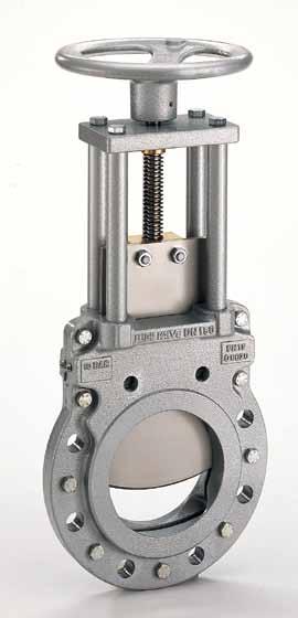
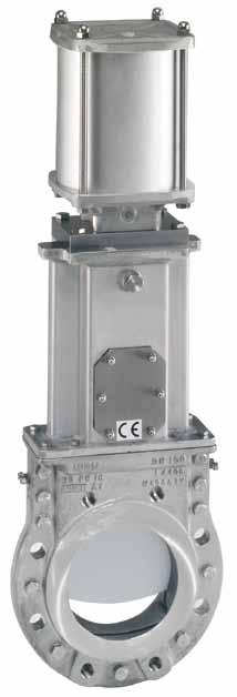
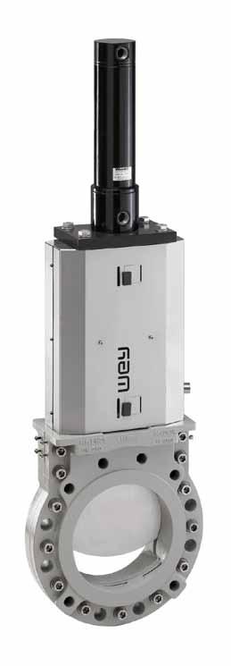
3 1. GENERAL 1.1 Safety Prior to any work or start-up and in order to ensure a proper functioning of our products. The instruction manual must be observed. Alterations on the products need our written approval. For consequential damages due to neglect of this direction, we have to reject any liability. This symbol marks safety and risk advice. Follow all such advice in order to prevent any damage to human life and objects. The installation must be carried out according to established procedures and only by qualified personnel. Project related data of valves, e.g. dimensions, materials and service range are found in the respective documentation. The responsibility for the service application remains the sole duty of the end-user. 1.2 Designated service Wey Knife gate valves are deigned to shut-off pressurized piping systems. Depending of the construction, finishing equipment and material valves can be used in fluid group 1 and 2 according to PED 2014/68/EU up to category III. Wey Knife gate valves may be installed as end-of-line service, provided that the valves are classified according to Art. 4 (3) PED 2014/68/EU. The max. working pressure must not exceed 0.73-times of the max. nominal pressure at room temperature. In addition the chapter 3.5 must be considered. For the valve design working limitations refer to the relevant project data documentation and the maintenance manual. Should the Wey Knife gate valve be installed in an explosion-protected area, the valve and the electrical and non-electrical equipment must meet the explosion zone RL 2014/34/EU, ATEX 1.3 Structure and function 1. Body with seal 2. Gate 3. Manual actuation 4. Pneumatical actuation 5. Electrical actuation 6. Hydraulic actuation Fig. 1 page 2 / 11
 Conformity / No notified body 1) Example 1) If applicable 2. TRANSPORTATION, STORAGE 2.")
4 1.4 Marking Manufacturer Type / Material Size / Flange drilling Year / Fabr. No. Nominal pressure Operating pressure Medium temp. Ambient temp. Air supply pressure 1) Conformity / No notified body 1) Example 1) If applicable 2. TRANSPORTATION, STORAGE 2.1 Transportation Transportation of the valves to their final destination (building site) shall take place in solid crates adapted to the valves size. The valves shall be protected against exterior damage and atmospheric exposure. Depending on the duration of transportation or storage and in view of the conditions, preservation shall take place by welding valves into PE-film or adding sufficient drying agent or equal. 2.2 Storage Until final installation the valves shall be stored in a dry, vented area. All function relevant parts shall be suitably covered against humidity, dust or other contamination. For longer storage periods or in case of unfavourable storage conditions, which might affect later functioning, all blank surfaces, e.g. stem, piston rod, sealing surfaces shall be suitably protected by long-term preservatives against corrosion. Factory applied preservatives shall be checked for possible transport damages and appropriately repaired, if necessary. For accessories mounted to the valves, such as electric actuators, limit switches, solenoids, etc., the respective storage instructions of the manufacturer shall be observed with priority. 3. INSTALLATION 3.1 Preparation before installation Before installation, please make sure that the subject Wey Knife gate valves is in conformance to the service conditions. The responsibility regarding applied service medium (corrosion resistance, pressure, temperature etc.) is with the end-user. Please check, if the valve to be installed in an explosion protected area, the valve meets the rules for the relevant zone. Not correctly aligned pipelines must, by all means, be corrected before installation in order to avoid tensions or even cracking of the valve body. Before final installation of the Wey Knife gate valves, any possibly applied corrosion protection shall be thoroughly removed. All parts, and in particular the gate, stem and piston rod shall be free of dust and dirt. 3.2 Installation site The mounting position must be chosen in such a way, that the knife gate valve can be checked and repaired at any time without risks. For repacking purpose the small side of the valve body shall be freely accessible (fig. 2). page 3 / 11

5 = Repacking feature Fig. 2 Additional directives and guidelines for installation and operation of explosion protection equipment, when installed into Ex-zones, must also be observed. Check if the equipment fulfils the safety requirements at site. For outdoor installations, the valves shall be protected at site with shields or covers against severe weather conditions like snow and ice. 3.3 Installation position Wey Knife gate valves will be installed in one of the positions shown in fig.3. Avoid a different installation position whenever possible. Fig. 3 Valves from size DN400 up with extended or heavy actuators, which are not vertical installed, should be supported on site. This is also recommended, if vibrations of the piping line may occur. 3.4 Flow and pressure direction The Wey Knife gate valve is a bi-directional design (fig.4). Depending on applications and valve design options a preferred flow direction must be considered. Liquid, gaseous and pneumatic conveyed solid fluids Flow direction Bi-directional possible (A,B) With the application of a wear ring from the entry side (B) Pressure direction Against gate bevel preferred (A) Powder and granulate at gravity discharge (vertical piping) Flow direction Pressure direction The gate bevel is positioned on the descending side, also when a cone insert is used (B) The preferred pressure direction must especially be considered, if the valve is working at % of the nominal pressure. page 4 / 11
 3 Cone insert / contracted bore (option) For difficult service conditions or for custom-made valves, please contact the manufacturer regarding the")
6 A B B Fig. 4 1 Gate bevel shape 2 Wear ring (option) 3 Cone insert / contracted bore (option) For difficult service conditions or for custom-made valves, please contact the manufacturer regarding the installation position. 3.5 Mounting Before mounting, check valves for possible transportation or storage damages. The valves shall be protected against construction work at site. For additional painting of the valves, the stem, piston rod, electric accessories and the valve gate protruding the body shall not be painted. Before any sand blasting, the valves shall be protected with covers. For valves with a stem extension, the pipeline flange must be exactly in line with the extension. The exact position of the flange holes in relation to the extension shall also be observed. Wey Knife gate valves are installed between two piping flanges with thru bolts and with bolts for body blind holes. Piping system misalignments must never be corrected using the valve body. Tighten bolts with caution, so that tensions in the body do not cause any cracking or breaking. No tilting, steady crosswise tightening. Bolt torques are to be observed. Table 1 Apply flange bolts according to fig. 5 into tapped blind holes. Pos. 1 : Pos. 2 : Pos. 3 : Pos. 1 Pos. 2 Pos. 3 Wrong assembly Tightened bolts shall not touch the bottom of the tapped blind holes. Correct assembly Also correct assembly. Insert stud, then tighten nut. Fig. 5 Valves of the middle flange design have flanges with through holes. page 5 / 11

7 Mounting acc. to fig. 6. Mounting as head valve Mounting between flanges Fig. 6 Wey Knife gate valves MF, MG, MH are provide as wafer type valve and as end-of-line valve. The chapter 1.2 must be considered. The dimensions of the flange bolts, its number are found in the documentation. Bolt thread [mm] Torque [Nm] Table1 Torque for flange screw M16 60 M M M M M M Based upon type of flange gasket, manufacturer's instructions are to be observed. It is to ensure that the flange connection is tight. Leakage can be dangerous to humans and environment The installation as an end or head valve requires special attention. In service, the downstream side must not be accessible for persons. See also chapter 1.2 and 4.2. For hazardous service media double transverse seals with respective leakage ports are incorporated and must be compellingly connected to ensure a controlled drain-off of possible leak fluids. After installation a correct earthing connection must be verified. This is normally done through the flange bolt connection. If this is not the case, the potential or guard wire must be drawn to the terminal clamp. Should there be a longer time period between mounting and power connection of electrically operated valves, it shall be ensured that the integral heater of the actuator is already connected during mounting of the valves in order to avoid the formation of condensate water (or protect actuator with suitable drying agent). 4. COMMISSIONING 4.1 General measures Before taking the valves into service, all function relevant parts (gate, stem, piston rod, etc.) shall be thoroughly cleaned. Damages, in particular to the seal caused by remains of grit, welding beads, and foreign rust or similar on the gate, are not covered by the warranty. For powder or granular service, it should be observed that wetted or humid media which has tendency to cake to the gate is thoroughly removed before start-up. page 6 / 11
8 The valves are factory preserved and lubricated for transportation and storage, but they require depending on the service conditions, another lubrication before start-up. Recommended are water-repellent, temperature resistant and long lasting lubricants. (Get your nearest supplier s recommendation). 4.2 Safety measures For automated valves installed in an area where valve movement could be dangerous for people (or animals/objects), it must be ensured by the user on-site that all moving parts are fenced with a suitable cover or protection shield. Should they not already be mounted, such covers are optionally available from manufacturer. Protection goals can also be reached through suitable on-site measure. Unprotected valves must not be commissioned. If hot gases or fluids are transported in the pipeline, ensure that no persons can touch the hot surfaces. It is also to ensure that no external interference of the control circuits can actuate the valve unintentionally. 4.3 Function Test Before commissioning a function test must be performed. Open and close the valve one time as a minimum. If the pipeline is pressure tested, it is to ensure that the applied pressure is not higher than the maximum allowed test pressure of the valve. 4.4 Pneumatically operated valves Preventive measures must be taken, that the maximum tank pressure is not exceeding ( 8 bar), also not in a breakdown situation. For operation of the actuator use only dry, filtered air acc. Class 4/5 ISO max. dust particle size 40 µm max. dust particle concentration 10 mg/m3 max. excess oil concentration 5 mg/m3 pressure dew point below minimal ambient temperature Solenoid valves shall be mounted as close as possible to the actuating cylinder. Air hoses, especially plastic pipes must be mounted and secured so that they cannot be unintentionally interrupted or torn. In order to keep a valve tight in its closed position, the piston must be permanently under pressure. The size of the air supply pipes has to be in relation to the air volume. Before start-up, all on-site mounted supply pipes and solenoid valves shall be thoroughly flushed and cleaned, if necessary. Factory mounted solenoid valves are normally provided without accessories like throttle or muffler. On-site regulations must therefore be observed. Pneumatically operated valves shall not be closed instantly in order to avoid the risk of pressure shocks. page 7 / 11
9 4.5 Hydraulically operated valves Before start-up, all on-site mounted supply pipes shall be thoroughly cleaned. Hydraulically actuated valves shall not be closed instantly in order to avoid the risk of pressure shocks. The maximum design air-supply pressure must not exceed. Higher air-supply pressure may damage the valve. 4.6 Electrically actuated valves For electrical installations observe local rules, standards and directives. Additional directives and guidelines for installation and operation of explosion protection equipment, when installed into Ex-zones must also be observed. Check if the equipment fulfils the safety requirements at site: After installation a correct earthing connection must be verified. This is normally done through the flange bolt connection. If this is not the case, the potential or guard wire must be drawn to the terminal clamp. For trouble-free commissioning of electric actuators, we recommend to call on our specially trained customer service specialist. On-site electric installations shall be in accordance with respective connecting diagram of the supplier. In addition, the specific operating instructions of the actuator supplier shall be observed. Before the first electrical operation, the valve gate shall be set to an intermediate position with the manual override, and then started. When connecting to the power supply, the phase sequence has to be observed. With wrong phase sequence, limit and torque switches are ineffective. The switch off-shall be in accordance to our instructions/diagrams, i.e.: - Switch-off in closing direction: usually by limit switches, exceptionally by torque - Switches (for abrasive service applications). - Switch-off in opening direction: by limit switches only, as the torque switch serves as overload protection. 5. MAINTENANCE 5.1 Inspection When in operation with dangerous fluids especially the leak-tightness against atmospheric area must be controlled on a regular basis. At possible indication of leakage must be repacked. 5.2 Operating cycles During one service year, at least four (4) operating cycles shall take place, whereby all components shall be checked. Under severe service conditions, such functional checks shall take place more frequently. 5.3 Repacking During a longer storage period of the Wey Knife gate valves or in case of great temperature fluctuations, the packing material in the transverse seal may shrink. This could lead to slight leakage through the transverse seal in the body chest area. Should a leakage be detected at the transverse seal which remains even after repeated actuation of the gate, the valve can be repacked easily and quickly while installed. During this work however, the valve should possibly not be under full service pressure. page 8 / 11
, then remove the screws from the valve body (fig. 7) Insert packing pellet into holes and compress firmly with packing tool.")
10 Mostly, it is only necessary to firmly tighten the four (4) packing screws on the side by 1-2 turns. Did the leakage not stop (after packing screws are fully tightened), then remove the screws from the valve body (fig. 7) Insert packing pellet into holes and compress firmly with packing tool. Repeat until valve is absolutely tight. Please observe that the valve gate is not pressed against the valve body due to the repacking. One-sided and too powerful repacking can cause the valve gate to jam. Seal cartridge Repacking screw Repacking tool 5.4 Seal replacement Fig. 7 Should a leakage through the bore passage occur, the cause is mostly damage or wear of the body seal. The valve body seal can only be replaced when the valve is removed from the pipeline. Seal replacement can be performed by trained personnel according instructions or at any time in our works. 5.5 Cleaning / Lubrication Stem rods, pull and piston rods shall be free of dirt and contamination and shall always be well lubricated. Lubrication points on handwheel bearings shall be regularly lubricated, based on the operating conditions, but at least every 3 months. Pneumatic cylinders with closing cushion are fitted with a self-lubricating rod seal. Any leakages on the cylinders require the exchange of all sealing components. For valves with electric actuators, the lubrication point on the drive should be especially observed. The respective operating instructions of the actuator supplier are binding. Depending on the service conditions of the valves, the gate is to clean and needs possibly slight lubrication. page 9 / 11
11 6. TROUBLE SHOOTING Trouble Possible Cause Elimination Leakage at gate in body chest area. Leakage in bore passage of valve Leakage through valve body halves Valve gate is not movable Closing or opening stroke ceasing or stagnating Transverse seal untight Transverse seal damaged Valve gate not completely closed; jammed particles between gate and body internals Jammed particles between stem nut, resp. clevis and body chest Body seal damaged Valve distorted during mounting Sealant between body halves damaged Actuating components damaged Valve clogged; Valve gate contaminated Insufficient supply pressure Solenoid valve dirty Piston rod seal damaged Valve clogged Repacking of transverse seal according to instructions Replacement of transverse seal according to instructions, cleaning of valve gate, if necessary replacement of gate Manual valves: - Open valve slightly and repeat closing action - Remove jammed particles Pneumatically and hydraulically operated valves: - Open valve slightly and repeat closing action - Check, if necessary new setting of clevis, resp. stroke - Remove jammed particles Electrically actuated valves: - Open valve slightly and repeat closing action, check, possibly reset switches (upon supplier s recommendation) - Remove jammed particles Remove valve, replace seals according to instructions Untighten flange bolts and re-tighten according to instructions Remove valve and replace sealant according to instructions Manual valves: - Check, clean stem or stem nut, replace if necessary, lubricate Pneumatically and hydraulically operated valves: - Check supply pressure Check if current onto solenoid exists. Check solenoid for damages Check hydraulic cylinder for damages (seal) - Clean and lubricate; if necessary replace damaged components acc. to supplier s instructions Electrically actuated valves: - Check if current exists - Check if motor defect - Check if limit switches defect or adjusted - Check if gear, stem or stem nut damaged - Clean and lubricate; if necessary replace damaged components acc. to supplier s instructions Remove valve, clean, possibly disassemble completely Pneumatically and hydraulically operated valves: Check supply pressure, possibly increase supply pressure Remove and clean solenoid valve, possibly install filter Remove and clean piston rod seal, exchange and lubricate cylinder seals Clean valve and lubricate Pressure loss on supply net Control pipe connection damaged Check pipe connections, tighten, replace if necessary Cylinder seals damaged - Check and replace cylinder seals, lubricate - Check piston rod seal, clean, lubricate page 10 / 11
12 7. REMOVAL Before removing the valve, consider that the pipe system can be under pressure and that hazardous media could get into the environment. Respective precaution measures must be taken. Actuators must, in principle, not be removed if pipeline system is under pressure. Electric actuators must be made current less, respectively disconnected from circuit. Pneumatic and hydraulic actuators must be pressure less and disconnected from supply lines. In case the pipe is removed on one side only, ensure before that the valve cannot be operated. Unintentional opening of the valve can be hazardous to people and environment due to drain-off of service medium. Unintentional closing can be very harmful, if a person (or body part) is within the area of the valve gate travel. 8. DISPOSAL Observe that sediments inside of valve or pipe can be harmful to people and environment. Respective precautions measures are to be taken. After finished service life the valve must be disposed skilful and in conformity with environmental regulations. 9. FINAL REMARKS All details given above are to our current up-to-date knowledge and shall provide, together with our technical documentation, information about our products and their range of applications. They are not thought to assure particular features of the products nor their suitability for a specific application. Faultless quality is assured within our General Sales Conditions. For any further information, please call any time on our Customer Service Department. Alterations reserved page 11 / 11
MODEL 200 KNIFE GATE VALVES INSTALLATION & MAINTENANCE MANUAL
 MODEL 200 KNIFE GATE VALVES INSTALLATION & MAINTENANCE MANUAL Index 1. List of components / General arrangement 2. Description 3. Handling 4. Installation 5. Actuators / Operation 6. Maintenance a. Changing
Bray/ VAAS O-Ported Series Knife Gate Valve 770/780 Series Operation and Maintenance Manual
 Bray/ VAAS Knife Gate Valve 770/780 Series Operations and Maintenance Manual Table of Contents Definition of Terms 1 Safety Instructions 1 Introduction 2 Unpacking 2 Storage 2 Installation 2 Commissioning
Installation & Operation Manual Proven Quality since 1892
 Content 1. ERIKS operating companies 2. Product description 3. Requirements for maintenance staff 4. Transport and storage 5. Function 6. Application 7. Installation 8. Maintenance 9. Service and repair
OPERATING MANUAL. Contents. Bottom outlet ball valve Type ecoline
 OPERATING MANUAL Bottom outlet ball valve Type ecoline Contents 1 General Information 2 Safety 3 Packing, Handling, Storing 4 Product description 5 Preparation, Assembly 6 Commissioning 7 Handling 8 Attendance
Operating instruction
 Operating instruction MV, XV, HG, HP, RKO, D2G, TV, BV, WB & SLV 1 Introduction 2 2 Stafsjö s knife gate valves 2 3 Technical information 2 3.1 Pressure test 2 3.2 Labelling 2 4 Storage 3 5 Transportation
97C COMPRESSOR KIT 12V PART NO C COMPRESSOR KIT 24V PART NO C COMPRESSOR KIT PART NO
 97C COMPRESSOR KIT 12V PART NO. 00097 97C COMPRESSOR KIT 24V PART NO. 02497 98C COMPRESSOR KIT PART NO. 00098 97C 98C IMPORTANT: It is essential that you and any other operator of this product read and
Components for air preparation and pressure adjustment. OUT port position ( ) connected Rear side. of IN port. Air tank. directly.
 connected Rear side. of IN port. Air tank. directly.") Components preparation and pressure adjustment ABP Overview ABP is a component that enables boosting by s only up to twice primary pressure (.0MPa max.) in combination with using air tank but not using
Components preparation and pressure adjustment ABP Overview ABP is a component that enables boosting by s only up to twice primary pressure (.0MPa max.) in combination with using air tank but not using
200 PSI COMPRESSORS - MODEL NUMBERS
 200 PSI COMPRESSORS - MODEL NUMBERS 380C AIR COMPRESSOR KIT PART NO. 38033 480C AIR COMPRESSOR KIT PART NO. 48043 380C 480C IMPORTANT: It is essential that you and any other operator of this product read
Type BBS-03, BBS-05, BBS-06, BBS-25
 Type BBS-03, BBS-05, BBS-06, BBS-25 Sterile connection elements Sterile Verbindungselemente Raccords union stériles Operating Instructions Bedienungsanleitung Manuel d utilisation 1. THE OPERATING INSTRUCTIONS
100C Air Compressor Kit
 10010 100C Air Compressor (standard mounting bracket, CE Spec) 10014 100C Air Compressor (no leader hose or check valve, CE Spec) 10016 100C Air Compressor (with Omega Bracket, CE Spec) IMPORTANT: It is
IMPORTANT SAFETY INSTRUCTIONS
 IMPORTANT SAFETY INSTRUCTIONS CAUTION - To reduce risk of electrical shock: - Do not disassemble. Do not attempt repairs or modifications. Refer to qualified service agencies for all service and repairs.
420C AIR COMPRESSOR KIT PART NO C AIR COMPRESSOR KIT PART NO
 420C AIR COMPRESSOR KIT PART NO. 42042 460C AIR COMPRESSOR KIT PART NO. 46043 420C 460C IMPORTANT: It is essential that you and any other operator of this product read and understand the contents of this
BUTTERFLY VALVES Series 800
 BUTTERFLY VALVES Series 800 WARNING Before proceeding read ALL instructions and become familiar with the equipment and associated drawings. Follow ALL applicable safety regulations and codes for pressurized
Apollo Standard Port, Full Port & One Piece Flanged Ball Valves Installation, Operation, & Maintenance Manual
 I854000.D Apollo Standard Port, Full Port & One Piece Flanged Ball Valves Installation, Operation, & Maintenance Manual Introduction This manual presents guidelines for the Installation, Operation and
INSTALLATION, OPERATION and MAINTENANCE MANUAL
 INSTALLATION, OPERATION and MAINTENANCE MANUAL TRUNNION MOUNTED BALL VALVE NEXTECH I ValvTechnologies, Inc. 5904 Bingle Road Houston, Texas 77092 U.S.A. Email: sales@valv.com www.valv.com 705_Nextech IOM
Spilt body Flange ball valve. TC-205MFF-PN1640 User Manual English Version. Document No: TC-205MFF-PN1640.Ur-manual. Date: 2007/04/2617. Version: 1.
 Spilt body Flange ball valve TC-205MFF-PN1640 Series PED Category I,II TC-205MFF-PN1640 User Manual English Version Use for company in Europe who will place the product on the market, please amend which
AIR COMPRESSOR OPERATING INSTRUCTION AND PARTS LIST
 AIR COMPRESSOR OPERATING INSTRUCTION AND PARTS LIST OIL-LESS TYPE IMPORTANT: PLEASE READ CAREFULLY BEFORE STARTING OPERATIONS. THE CONTENTS ARE FOR GENERAL INFORMATION OF ALL THE SIMILAR MODELS. Record
ROTATING DISK VALVES INSTALLATION AND MAINTENANCE 1. SCOPE 3 2. INFORMATION ON USAGE 3 3. VALVE TYPES 3 4. OPERATORS 5 5. VALVE CONSTRUCTION 6
 Sub Section INDEX Page Number 1. SCOPE 3 2. INFORMATION ON USAGE 3 3. VALVE TYPES 3 4. OPERATORS 5 5. VALVE CONSTRUCTION 6 6. INSTALLATION AND OPERATION 6 7. MAINTENANCE 8 8. REPAIR 9 9. ASSEMBLY 10 10.
FLANGED TWO-PIECE BALL VALVES
 INTRODUCTION This instruction manual includes installation, operation, and maintenance information for FNW flanged split-body ball valves. This manual addresses lever operated ball valves only. Please
Technical Data Sheet TI-F50 Locking Units series KFH
 English translation of German original Locking Units series KF Further important practical advice is given in Operating Manual BA-F50., Rod diameter 18 mm 50 mm øz 8 L 2 6 x 6 0 min. 4x30 KF 18 to KF 32,
400H HARDMOUNT AIR COMPRESSOR KIT PART NO H HARDMOUNT AIR COMPRESSOR KIT PART NO
 400H HARDMOUNT AIR COMPRESSOR KIT PART NO. 40042 450H HARDMOUNT AIR COMPRESSOR KIT PART NO. 45042 400H 450H IMPORTANT: It is essential that you and any other operator of this product read and understand
444C DUAL PERFORMANCE VALUE PACK
 (Chrome) PART NO. 44432 IMPORTANT: It is essential that you and any other operator of this product read and understand the contents of this manual before installing and using this product. SAVE THIS MANUAL
FLANGED TWO-PIECE BALL VALVES
 INTRODUCTION This instruction manual includes installation, operation, and maintenance information for FNW flanged split-body ball valves. This manual addresses lever operated ball valves only. Please
250C-IG COMPRESSOR KIT 12V PART NO C-IG COMPRESSOR KIT 24V PART NO
 250C-IG COMPRESSOR KIT 12V PART NO. 25050 250C-IG COMPRESSOR KIT 24V PART NO. 25058 IMPORTANT: It is essential that you and any other operator of this product read and understand the contents of this manual
Wafer Check Valve. Contents. User s Manual. (1) Be sure to read the following description of our product warranty 1
 Be sure to read the following description of our product warranty 1") Serial No. H-V066-E-3 Wafer Check Valve User s Manual Contents (1) Be sure to read the following description of our product warranty 1 (2) General operating instructions 2 (3) General instructions for
Serial No. H-V066-E-3 Wafer Check Valve User s Manual Contents (1) Be sure to read the following description of our product warranty 1 (2) General operating instructions 2 (3) General instructions for
Engineering Data Sheet
 Page 1 of 6 CE MARKING AND THE PRESSURE EQUIPMENT DIRECTIVE 97/23/EC Valves must be installed into a well designed system and it is recommended that the system be inspected in accordance with the appropriate
Pneumatic proportional controller Types M Types FM Function tested for use of the float in Ex-zone 0
 Operating Manual LTIA5E Pneumatic proportional controller Types M Types FM Function tested for use of the float in Ex-zone 0 Contents 1. Safety Instructions 2. Conformity to standards 3. Technical data
400C & 450C DUAL PERFORMANCE VALUE PACKS
 (Chrome) PART NO. 40013 (Silver) PART NO. 45012 (Chrome) PART NO. 45013 IMPORTANT: It is essential that you and any other operator of this product read and understand the contents of this manual before
RS(H)10,15 USER MANUAL. Read the complete manual before installing and using the regulator.
10,15 USER MANUAL. Read the complete manual before installing and using the regulator.") RS(H)10,15 USER MANUAL Read the complete manual before installing and using the regulator. WARNING INCORRECT OR IMPROPER USE OF THIS PRODUCT CAN CAUSE SERIOUS PERSONAL INJURY AND PROPERTY DAMAGE. Due to
RS(H)10,15 USER MANUAL Read the complete manual before installing and using the regulator. WARNING INCORRECT OR IMPROPER USE OF THIS PRODUCT CAN CAUSE SERIOUS PERSONAL INJURY AND PROPERTY DAMAGE. Due to
KTM OM-2 SPLIT BODY FLOATING BALL VALVES INSTALLATION AND MAINTENANCE INSTRUCTIONS
 Before installation these instructions must be fully read and understood SECTION 1 - STORAGE 1.1 Preparation and preservation for storage All valves should be properly packed in order to protect the parts
Type 2000 INOX. Quickstart. English Deutsch Français. 2/2-way angle seat valve 2/2-Wege Schrägsitzventil Vanne à siège incliné 2/2 voies
 Type 2000 INOX 2/2-way angle seat valve 2/2-Wege Schrägsitzventil Vanne à siège incliné 2/2 voies Quickstart English Deutsch Français Contents 1 QUICKSTART... 2 2 CONTACT ADDRESS... 2 3 INTENDED USE...
KECKLEY. Installation, Operation, and Maintenance Manual. Style KGV - Knife Gate Valve
 KECKLEY Installation, Operation, and Maintenance Manual Style KGV - Knife Gate Valve Table of Contents Introduction and Safety... 3 Safety message levels... 3 User health and safety... 3-4 Transportation
250C-IG COMPRESSOR KIT 12V PART NO C-IG COMPRESSOR KIT 24V PART NO
 250C-IG COMPRESSOR KIT 12V PART NO. 25050 250C-IG COMPRESSOR KIT 24V PART NO. 25058 IMPORTANT: It is essential that you and any other operator of this product read and understand the contents of this manual
INSTRUCTIONS AND MAINTENANCE MANUAL SERIES: RT
 INSTRUCTIONS AND MAINTENANCE MANUAL 05/11/2015 SERIES: RT cmo @cmo.es http://www.cmo.es page 1 ASSEMBLY THE RT VALVE COMPLIES WITH THE FOLLOWING: Machinery Directive: DIR 2006/42/EC (MACHINERY) Pressure
Installation, Operating & Maintenance Instructions. All-metal gate valve with extended pneumatic actuator. Series 48 DN mm (I.D.
 Installation, Operating & Maintenance Instructions All-metal gate valve with extended pneumatic actuator Series 48 DN 16 320 mm (I.D. ⅝" 12") This manual is valid for the following product ordering numbers:
Manual Actuated Boiler Blowdown Valves
 Manual Actuated Boiler Blowdown Valves Installation and Maintenance Instructions 1. Safety information 2. General product information 3. Installation 4. Operation 5. Maintenance 6. Spare parts p.1 1. Safety
Contents. 1. General information BROEN BALLOMAX Steel Ball Valves Approvals Quality Management...2
 Contents 1. General information...2 1.1 BROEN BALLOMAX Steel Ball Valves...2 1.2 Approvals...2 1.3 Quality Management...2 2. Preoperational Instructions and Precautions...2 3. Plates...3 4. Transport and
Installation, operation & maintenance manual - original version
 Installation, operation & maintenance manual - original version AVK gate valves for water and wastewater Series 01, 02, 06, 12, 15, 18, 20, 26, 32, 33, 36, 38, 50, 55 and 636 COPYRIGHT AVK GROUP A/S 2018
MSC-P and MSC-N Manifolds for Steam Distribution and Condensate Collection
 1170850/1 IM-P117-36 ST Issue 1 MSC-P and MSC-N Manifolds for Steam Distribution and Condensate Collection Installation and Maintenance Instructions 1. Safety information 2. General product information
INSTRUCTIONS AND MAINTENANCE MANUAL SERIES: K
 INSTRUCTIONS AND MAINTENANCE MANUAL 05/09/2014 SERIES: K cmo@cmo.es http://www.cmo.es Page 1 ASSEMBLY DESCRIPTION Machinery Directive: DIR 2006/42/EC (MACHINERY) Pressure Equipment Directive: DIR 97/23/EC
Telefon (+45) Telefax (+45)
 Telefax (+45)") Uni-Valve A /S VENTILER & INSTRUMENTER Telefon (+45) 43 43 82 00 Telefax (+45) 43 43 74 75 mail@uni-valve.com www.uni-valve.com UNI-S83 / S84 3/4-way ball valve Installation and Operating manual 3/4-WAY
Uni-Valve A /S VENTILER & INSTRUMENTER Telefon (+45) 43 43 82 00 Telefax (+45) 43 43 74 75 mail@uni-valve.com www.uni-valve.com UNI-S83 / S84 3/4-way ball valve Installation and Operating manual 3/4-WAY
3-PIECE BALL VALVE, 3600 PSI/ PN 248, WITH ISO DIRECT MOUNTING PAD 306M SERIES/ PED Category II
 3-PIECE BALL VALVE, 3600 PSI/ PN 248, WITH ISO DIRECT MOUNTING PAD 306M SERIES/ PED Category II 306M User Manual English Version Use for company in Europe who will place the product on the market, please
Pneumatic switch module 3/2-way valve (On/Off) Types P Types FP Function tested for use of the float in Ex-zone 0
 Types P Types FP Function tested for use of the float in Ex-zone 0") Operating Manual LTIA3E Pneumatic switch module 3/2-way valve (On/Off) Types P Types FP Function tested for use of the float in Ex-zone 0 Contents 1. Safety Instructions 2. Conformity to standards 3. Technical
Operating Manual LTIA3E Pneumatic switch module 3/2-way valve (On/Off) Types P Types FP Function tested for use of the float in Ex-zone 0 Contents 1. Safety Instructions 2. Conformity to standards 3. Technical
INSTALLATION, MAINTENANCE & OPERATING INSTRUCTIONS 2-4 REDUCED PORT/ FULL PORT (5700/6700) ANSI CLASS 150/300/600/900/1500/2500 TRUNNION BALL VALVES
 ANSI CLASS 150/300/600/900/1500/2500 TRUNNION BALL VALVES") PBV-USA,Inc. 12735 Dairy Ashford. Stafford, Texas USA 77477 281-340-5400; 800-256-6193 FAX: 281-340-5499 INDUSTRIAL BALL VALVES IM0 69 April 2001 Rev 9 INSTALLATION, MAINTENANCE & OPERATING INSTRUCTIONS
PBV-USA,Inc. 12735 Dairy Ashford. Stafford, Texas USA 77477 281-340-5400; 800-256-6193 FAX: 281-340-5499 INDUSTRIAL BALL VALVES IM0 69 April 2001 Rev 9 INSTALLATION, MAINTENANCE & OPERATING INSTRUCTIONS
PC3_ and PC4_ Pipeline Connectors
 1283050/4 IM-P128-06 ST Issue 4 PC3_ and PC4_ Pipeline Connectors Installation and Maintenance Instructions 1. Safety information 2. Description PC30 shown 3. Installation 4. Welding of pipeline connector
PRS(TC)4,8 USER MANUAL. Read the complete manual before installing and using the regulator.
4,8 USER MANUAL. Read the complete manual before installing and using the regulator.") PRS(TC)4,8 USER MANUAL Read the complete manual before installing and using the regulator. WARNING INCORRECT OR IMPROPER USE OF THIS PRODUCT CAN CAUSE SERIOUS PERSONAL INJURY AND PROPERTY DAMAGE. Due to
PRS(TC)4,8 USER MANUAL Read the complete manual before installing and using the regulator. WARNING INCORRECT OR IMPROPER USE OF THIS PRODUCT CAN CAUSE SERIOUS PERSONAL INJURY AND PROPERTY DAMAGE. Due to
Type 0404 / /2-way solenoid valve 2/2-Wege-Magnetventil Électrovanne 2/2 voies Operating Instructions Bedienungsanleitung Manuel d utilisation
 Type 0404 / 5404 2/2-way solenoid valve 2/2-Wege-Magnetventil Électrovanne 2/2 voies Operating Instructions Bedienungsanleitung Manuel d utilisation 1 OPERATING INSTRUCTIONS The operating instructions
Operation Manual Air Saver Unit ASV5000 Series
 9IM-V066-b Operation Manual Air Saver Unit ASV5000 Series Thank you for your choice of Kuroda Pneumatics LTDs product on this time. Please read this operation manual carefully and use the product correctly.
MODEL NUMBER: M20005 AIR SOURCE KIT. 30% Duty Compressor on. 2.0 Gallon Air Tank SAVE THIS MANUAL FOR FUTURE REFERENCE
 MODEL NUMBER: M20005 AIR SOURCE KIT 30% Duty Compressor on 2.0 Gallon Air Tank SAVE THIS MANUAL FOR FUTURE REFERENCE USER MANUAL IMPORTANT SAFETY INSTRUCTIONS CAUTION - To reduce risk of electrical shock
Model PSI Compressor with 3-Gallon Air Tank 12VDC
 Model 6350 150 PSI Compressor with 3-Gallon Air Tank 12VDC IMPORTANT: It is essential that you and any other operator of this product read and understandd the contents of this manual before installing
lead water to the next level NEEDLE VALVES
 lead water to the next level NEEDLE VALVES INDEX 1. GENERAL INFORMATION 1.1 Tips for Long Term Operation 1.2 Instructions for Shipment & Warehousing 2. PRODUCT INFORMATION 2.1 Design Limits 2.2 Valve Marking
DelVal Flow Controls Private limited
 DelVal Flow Controls Private limited (A DIVISION OF DelTech CONTROLS LLC, USA) DelVal Series 50/5, 5A/5B Butterfly Valves INSTALLATION, OPERATION AND MAINTENANCE MANUAL ENGINEERING DATA SHEET E.D.S. NO
Installation, Operating and Maintenance Instructions. V914 Cast Iron Flanged Swing Check Valve V914
 Installation, Operating and Maintenance Instructions V914 Cast Iron Flanged Swing Check Valve V914 THE PRESSURE EQUIPMENT DIRECTIVE 97/23/EC and CE MARKING The Pressure Equipment Regulations 1999 (SI 1999/2001)
FLANGED MULTI-PORT BALL VALVES
 INTRODUCTION This instruction manual includes installation, operation and maintenance information for flanged multi-port ball valves. This manual addresses lever operated ball valves only. Please refer
SPECIFICATIONS Type: Twin stack, single phase Tank: 4 gallon Air Output: PSI; PSI Max PSI: 125 PSI HP: 1.
 2 GALLON TWIN STACK AIR COMPRESSOR Model: 9526 DO NOT RETURN TO STORE. Please CALL 800-348-5004 for parts and service. CALIFORNIA PROPOSITION 65 WARNING: You can create dust when you cut, sand, drill or
Type 2080 FALTENBALGVENTIL BELLOWS VALVE VANNE A SOUFFLET. Operating Instructions. Bedienungsanleitung Manuel d utilisation
 Type 2080 FALTENBALGVENTIL BELLOWS VALVE VANNE A SOUFFLET 2/2-way valve with piston actuator and PTFE bellows 2/2-Wege Ventil mit Kolbenantrieb und PTFE-Faltenbalg Vanne 2/2 voies avec entraînement à piston
INSTALLATION, OPERATION AND MAINTENANCE GUIDE
 INSTALLATION, OPERATION AND Placement in Pipeline System When installing Process Development & Control s ElastoTITE Elastomer-Hinged Check Valves in a pipeline, a minimum of five pipe diameters should
LRS(H)4 USER MANUAL. Read the complete manual before installing and using the regulator.
4 USER MANUAL. Read the complete manual before installing and using the regulator.") LRS(H)4 USER MANUAL Read the complete manual before installing and using the regulator. WARNING INCORRECT OR IMPROPER USE OF THIS PRODUCT CAN CAUSE SERIOUS PERSONAL INJURY AND PROPERTY DAMAGE. Due to the
LRS(H)4 USER MANUAL Read the complete manual before installing and using the regulator. WARNING INCORRECT OR IMPROPER USE OF THIS PRODUCT CAN CAUSE SERIOUS PERSONAL INJURY AND PROPERTY DAMAGE. Due to the
200 PSI HIGH-FLOW AIR SOURCE KIT
 200 PSI HIGH-FLOW AIR SOURCE KIT 50% Duty Compressor on 2.0 Gallon Air Tank PART NO. 20008 IMPORTANT: It is essential that you and any other operator of this product read and understand the contents of
200 PSI FAST-FILL AIR SOURCE KIT
 200 PSI FAST-FILL AIR SOURCE KIT 55% Duty Compressor on 2.0 Gallon Air Tank PART NO. 20007 IMPORTANT: It is essential that you and any other operator of this product read and understand the contents of
OPERATION and MAINTENANCE Guide
 Catalog No. AIR1000 Winch and Hoist OPERATION and MAINTENANCE Guide Cat. No. AIR1000 1250 Lb. Single Line Pull READ THIS BEFORE OPERATING UNIT INSTALLATION: Mount on clean, flat surface. Use 1/2" mounting
INSTRUCTIONS AND MAINTENANCE MANUAL SERIES: FK
 INSTRUCTIONS AND MAINTENANCE MANUAL 04/09/2014 SERIES: FK cmo@cmo.es http://www.cmo.es Page 1 ASSEMBLY THE FK VALVE COMPLIES WITH THE FOLLOWING: Machinery Directive: DIR 2006/42/EC (MACHINERY) Pressure
MUELLER. Xp, & Lineseal 350 Butterfly Valves
 Installation/Operating Manual MUELLER Lineseal Iii, Lineseal Xpii, Lineseal Xp, & Lineseal 350 Butterfly Valves! WARNING: 1. Read and follow instructions carefully. Proper training and periodic review
MODEL NUMBER: PSI AIR SOURCE KIT 200 PSI Compressor on 2.0 Gallon 200 PSI Air Tank
 IMPORTANT SAFETY INSTRUCTIONS CAUTION - To reduce risk of electrical shock or Electrocution: MODEL NUMBER: 20008 200 PSI AIR SOURCE KIT 200 PSI Compressor on 2.0 Gallon 200 PSI Air Tank IMPORTANT: It is
42045 Heavy Duty ADA Base Model Kit: 85/105 PSI (ADA Compressor Only) Heavy Duty ADA Base Model Kit: 110/145 PSI (ADA Compressor Only)
 Heavy Duty ADA Base Model Kit: 110/145 PSI (ADA Compressor Only)") 42045 Heavy Duty ADA Base Model Kit: 85/105 PSI (ADA Compressor Only) 42047 Heavy Duty ADA Base Model Kit: 110/145 PSI (ADA Compressor Only) 45052 Constant Duty ADA Base Model Kit: 85/105 PSI (ADA Compressor
42045 Heavy Duty ADA Base Model Kit: 85/105 PSI (ADA Compressor Only) 42047 Heavy Duty ADA Base Model Kit: 110/145 PSI (ADA Compressor Only) 45052 Constant Duty ADA Base Model Kit: 85/105 PSI (ADA Compressor
KENNEDY VALVE OPERATION & MAINTENANCE MANUAL
 2 54 ROTATING DISC GATE VALVE OPERATION & MAINTENANCE MANUAL Rel. 5/27/16 1 TABLE OF CONTENTS 3 General 3 Receipt & Inspection 4 Gate Valve Storage & Handling 5 6 Installation 7 Operation 8 Field Testing
Needle valve. Contents. User s Manual. (1) Be sure to read the following warranty clauses of our product 1. (2) General operating instructions 2
 Be sure to read the following warranty clauses of our product 1. (2) General operating instructions 2") Serial No. H-V024-E-7 Needle valve User s Manual Contents (1) Be sure to read the following warranty clauses of our product 1 (2) General operating instructions 2 (3) General instructions for transportation,
Serial No. H-V024-E-7 Needle valve User s Manual Contents (1) Be sure to read the following warranty clauses of our product 1 (2) General operating instructions 2 (3) General instructions for transportation,
Translation assembly instructions with operating manual and technical appendix
 BA 4.2 - MRL Pneumatic cylinder for knife gate valves Type EC and ECS-O/C Example illustration, not all possible type variants are shown! Translation assembly instructions with operating manual and technical
Index Table. Model 794. Installation, Operating and Maintenance Instructions
 CLOCKWISE MANUAL MAKING INTO CCW TABLE Index Table Model 794 Installation, Operating and Maintenance Instructions Black & Webster Products Division 545 Hupp Ave. P.O. Box 831, Jackson, Michigan 49204 2009
ATD LB PRESSURE BLASTER INSTRUCTION MANUAL
 ATD-8402 90LB PRESSURE BLASTER INSTRUCTION MANUAL SAVE THESE INSTRUCTIONS SAFETY INSTRUCTIONS FOR SANDBLASTER 1. Before opening the tank release the air pressure on the sand tank. To do this, turn off
RARS5000 AIR BODY SAW OWNER S OPERATING MANUAL
 RARS5000 AIR BODY SAW OWNER S OPERATING MANUAL DESCRIPTION 1. No mar 2. No mar tip 3. Housing grip 4. Trigger 5. Air inlet 6. Air inlet plug 7. Plastic board Important! It is essential that you read the
ULTRA-LIGHT DUTY ONBOARD AIR SYSTEM
 ULTRA-LIGHT DUTY ONBOARD AIR SYSTEM PART NO. 10000 IMPORTANT: It is essential that you and any other operator of this product read and understand the contents of this manual before installing and using
Operating Manual FSV, FSÖV, SSVF
 Contents 1. General Remarks... 1 1.1. Marking... 2 1.2. Tightness of the Quick-Closing Valve... 2 1.3. Medium... 2 1.4. Ambient and Medium Temperature... 3 1.5. Vibrations... 3 1.6. Pipe Tensions... 3
KTM V-PORT CONTROL BALL VALVES INSTALLATION AND OPERATION MANUAL
 Please read through this manual completely before operating the valves SECTION 2 - SPECIFICATIONS The safety of the valves and conformity with your equipment should be checked by the design engineer or
TECHNICAL DATA MAINTENANCE AIR COMPRESSOR MODEL G-1
 Dry 131h 1. DESCRIPTION The Viking Model G-1 Maintenance Air Compressor is an electric motor-driven, aircooled, single-stage, oil-less compressor. The unit is equipped with a check valve and provides a
USER MANUAL Version: 1/2017
 ZETKAMA Sp. z o.o. ul. 3 Maja 12 PL 57-410 Ścinawka Średnia DIFREN PRESSURE REGULATING VALVE USER MANUAL Version: 1/2017 Fig. 223 Data: 01.01.2017 TABLE OF CONTENS 1. Product description 2. Requirements
30T A/Manual Hydraulic Shop Press
 30T A/Manual Hydraulic Shop Press Operation Manual 1 1. Important Information 1.1 Safety Information 1.1.1 Hazard Symbols Used in the Manuals This manual includes the hazard symbols defined below when
Mounting and operating instructions EB 2530 EN. Self-operated Pressure Regulator. Pressure Reducing Valve Type M 44-2
 Self-operated Pressure Regulator Pressure Reducing Valve Type M 44-2 Type M 44-2, connection G 1 4, K VS = 0.15 Type M 44-2, connection G 1, K VS = 6 Fig. 1 Type M 44-2 Pressure Reducing Valve Mounting
accidents which arise due to non-observance of these instructions and the safety information herein. SPECIFICATIONS
 18 GAUGE 1-1/4 INCH BRAD NAILER Model: 7611 CALIFORNIA PROPOSITION 65 WARNING: You can create dust when you cut, sand, drill or grind materials such as wood, paint, metal, concrete, cement, or other masonry.
Type 3709 Pneumatic Lock-up Valve. Translation of original instructions. Mounting and Operating Instructions EB 8391 EN
 Type 3709 Pneumatic Lock-up Valve Translation of original instructions Mounting and Operating Instructions EB 8391 EN Edition July 2017 Note on these mounting and operating instructions These mounting
Mounting and Operating Instructions EB 3007 EN. Self-operated Pressure Regulators. Differential Pressure Regulators (opening) Type Type 42-25
 Type Type 42-25") Self-operated Pressure Regulators Differential Pressure Regulators (opening) Type 42-20 Type 42-25 Type 42-20 Differential Pressure Regulator Type 42-25 Differential Pressure Regulator Mounting and Operating
Self-operated Pressure Regulators Differential Pressure Regulators (opening) Type 42-20 Type 42-25 Type 42-20 Differential Pressure Regulator Type 42-25 Differential Pressure Regulator Mounting and Operating
450P AUTOMATIC PORTABLE COMPRESSOR EXTREME SERIES
 EXTREME SERIES PART NO. 45043 IMPORTANT: It is essential that you and any other operator of this product read and understand the contents of this manual before installing and using this product. SAVE THIS
ATEX installation and service instruction
 ATEX installation and service instruction 2014/34/EU for Cat 1 Zone 20 Knife gate valves series XV, MV, MP, HG (HP), HL, HX, WB (WB11, 12, 14), RKO, JTV, D2G ATEX installation and service instruction 2014/34/EU
Control Valves ZK 610 ZK 613
 Control Valves ZK 610 ZK 613 Original Installation Instructions 819043-02 Contents Foreword... 3 Availability... 3 Formatting features in the document... 3 Safety... 4 Use for the intended purpose... 4
CARTRIDGE FILTERS TECHNICAL MANUAL MT 080. Installation, commissioning and maintenance instructions. 08/02 Edition
 CARTRIDGE FILTERS TECHNICAL MANUAL MT 080 Installation, commissioning and maintenance instructions 08/02 Edition 1 2 CONTENTS 1.0 PAGE INTRODUCTION 1.1 MAIN FEATURES 1.2 OPERATION 1.3 CLOSING OF HEAD WITH
INTENDED USE TECHNICAL SPECIFICATIONS
 1/2IN. HEAVY-DUTY AIR IMPACT WRENCH OWNER S MANUAL WARNING: Read carefully and understand all INSTRUCTIONS before operating. Failure to follow the safety rules and other basic safety precautions may result
Mounting and Operating Instructions EB 2558 EN. Self-operated Pressure Regulators. Type Pressure Build-up Regulator
 Self-operated Pressure Regulators Type 2357-31 Pressure Build-up Regulator with safety function and integrated excess pressure valve Type 2357-31 with non-return unit at port C Ports A and B with soldering
HEAVY DUTY KNIFE GATE VALVE
 HEAVY DUTY KNIFE GATE VALVE The (SER.22) model knife gate is a bi-directional lug type valve designed according to MSS-SP-81 and TAPPI TIS 405-8 for industrial service applications. The completely new
TITAN FLOW CONTROL, INC.
 PREFACE: This manual contains information concerning the installation, operation, and maintenance of Titan Flow Control (Titan FCI) Simplex Basket Strainers. To ensure efficient and safe operation of Titan
Differential Pressure Regulator Type Type 45-6 (0.1 to 1 bar, DN 15) Mounting and Operating Instructions EB 3226 EN
 Mounting and Operating Instructions EB 3226 EN") Differential Pressure Regulator Type 45-6 Type 45-6 (0.1 to 1 bar, DN 15) Mounting and Operating Instructions EB 3226 EN Edition March 2008 Contents Contents Page 1 Design and principle of operation...................
Differential Pressure Regulator Type 45-6 Type 45-6 (0.1 to 1 bar, DN 15) Mounting and Operating Instructions EB 3226 EN Edition March 2008 Contents Contents Page 1 Design and principle of operation...................
SIX R (P ) AND SEVEN R (P ) POSITION CYLINDERS Service Information
 AND SEVEN R (P ) POSITION CYLINDERS Service Information") SIX R431006322 (P -063892-00001) AND SEVEN R431006321 (P -063981--00002) POSITION CYLINDERS Service Information The six and seven position cylinders are medium duty pneumatic positioning devices that operate
SIX R431006322 (P -063892-00001) AND SEVEN R431006321 (P -063981--00002) POSITION CYLINDERS Service Information The six and seven position cylinders are medium duty pneumatic positioning devices that operate
Operating and Maintenance Instructions. VAG BETA 200 Gate Valve
 Operating and Maintenance Instructions VAG BETA 200 Gate Valve KAT-B 1010 Edition 1-12/2017 Table of Contents 1 General 3 1.1 Safety 3 1.2 Proper use 3 1.3 Identification 3 VAG reserves the right to make
Declaration of Conformity as per Directive 97/23/EC
 Declaration of Conformity as per Directive 97/23/EC The manufacturer declares that:, 47906 Kempen, Germany Multi-way diverting valves Series 29a and Series 29b, with packing with lever 1. The valves are
Type /2-Way Globe Valve 3/2-Wege-Geradsitzventil Vanne à siège droit 3/2 voies Operating Instructions Bedienungsanleitung Manuel d utilisation
 3/2-Way Globe Valve 3/2-Wege-Geradsitzventil Vanne à siège droit 3/2 voies Operating Instructions Bedienungsanleitung Manuel d utilisation We reserve the right to make technical changes without notice.
120 PSI FAST-FILL AIR SOURCE KIT 25% Duty Compressor on 1.5 Gallon Air Tank
 120 PSI FAST-FILL AIR SOURCE KIT 25% Duty Compressor on 1.5 Gallon Air Tank PART NO. 20003 IMPORTANT: It is essential that you and any other operator of this product read and understand the contents of
Operating Manual. R280 Pressure regulator made of brass. 1. Intended Use
 Pressure regulator made of brass Operating Manual 1. Intended Use Line or outlet pressure regulators- /reducer for Air, gases and liquids which is designed to effect reduction to a downstream pressure
KBV21i and KBV40i Key Operated Boiler Blowdown Valves Installation and Maintenance Instructions
 4059051/3 IM-P405-48 EMM Issue 3 KBV21i and KBV40i Key Operated Boiler Blowdown Valves Installation and Maintenance Instructions 1. Safety information 2. General product information 3. Installation 4.
Installation and operating manual. Pneumatic control station LK product no: PCS 1-10
 LK product no: PCS 1-10 Article no: 74503 Revision:8 Article no: 74503 Revision: 8 2 (23) Contents 1. General information... 5 2. Safety precautions... 5 2.1 Significance of symbols... 5 2.2 Explanatory
VALVCHEQ BACKFLOW PREVENTERS FIGURE RP03
 Reduce pressure zone device suitable for high and medium hazard rated applications Flanged end connections FEATURES GENERAL APPLICATION The RP03 provides protection from both backsiphonage and backpressure
450P- RV AUTOMATIC PORTABLE COMPRESSOR EXTREME SERIES
 450P- RV AUTOMATIC PORTABLE COMPRESSOR EXTREME SERIES PART NO. 45053 IMPORTANT: It is essential that you and any other operator of this product read and understand the contents of this manual before installing