SCHUCK INSTALLATION/OPERATION MANUAL Nozzle Check Valve Type RV Translation of the original German Operation Manual. Keep for future use!
|
|
|
- Amelia Neal
- 6 years ago
- Views:
Transcription


1 SCHUCK INSTALLATION/OPERATION MANUAL Nozzle Check Valve Type RV Translation of the original German Operation Manual Keep for future use!
2 Introduction This manual is written for installation, operating, maintenance and supervisory personnel. This manual also describes components and auxiliary units that are not included or are only partially included in the scope of supply. The manual must be read, understood and observed by the user. We emphasize that Franz Schuck GmbH assumes no liability for damage or malfunctions arising from non-compliance with this manual. With regard to the illustrations and information in this manual, we reserve the right to make technical modifications. Copyright The copyright for this manual remains with Franz Schuck GmbH. The instructions and drawings contained herein may not be reproduced or disseminated either fully or in part, nor used for competitive purposes or communicated to other parties without authorization. Contact address Franz Schuck GmbH Daimlerstraße Steinheim GERMANY Phone +49 (7329) Fax +49 (7329) info@schuck-group.com
3 Table of Contents Table of Contents Chapter 1 Preliminary remarks Legal notes Application range 1-1 Chapter 2 Safety Fundamental safety instructions General Intended use Organizational measures Special hazard points Workplace and personal protective gear 2-3 Chapter 3 Description System overview Construction and design Sealing off the outlet Sealing out the atmosphere Actuation Accessories and connections Identification plate 3-3 Chapter 4 Assembly Preparation As-delivered condition Inspection Storage Transport Installation General installation instructions Insulating joints with flanges Welding ends version Short pattern version I
4 Table of Contents Pipeline and flow conditions Valve installation Testing Function test 4-11 Chapter 5 Operation Safety instructions for operation Operation 5-1 Chapter 6 Maintenance Inspection/Maintenance Regular maintenance Recommended inspection and maintenance intervals Ventilation/drainage (optional) Faults and troubleshooting Repairs 6-4 Chapter 7 Appendix Tightening sequence for flange bolts Conversion factors Calculation formula to determine the carbon equivalent (CEV) Calculation formula (standard) Calculation formula for steels with different consistencies Marking of packages Marking of packages according to DIN and ISO R Schuck symbols transporting and unpacking packages II
5 Preliminary remarks 1 Preliminary remarks CAUTION Danger of consequential damage due to incorrect operation, maintenance and/ or handling! We explicitly emphasize that we assume no liability for damage or malfunctions arising from non-compliance with this manual. Therefore it is important to comply with all instructions in this manual! This manual is to provide technicians and users with the necessary information for assembly and adjustment work and to help in performing work quickly and correctly. For your own safety, read this manual carefully and pay particular attention to the highlighted tips. In any case, keep this manual to hand. Pay special attention to all safety instructions in this manual. You will find the safety instructions in Chapter 2, in the introductions to chapters and before practical instructions. The General Terms and Conditions of the company apply exclusively to all deliveries and performances made by Franz Schuck GmbH, including any future transactions. 1.1 Legal notes The component may only be installed and operated by skilled personnel. Please check parts upon receipt for any possible damage that may have occurred during transport. Only undamaged parts may be fitted or used. No warranty can be claimed if maintenance work is neglected or carried out incorrectly. Only original spare parts guarantee quality, reliability and exchangeability. Any modification(s) of the component are in general prohibited by Franz Schuck GmbH. The manufacturer guarantee becomes void if this prohibition is not complied with! 1.2 Application range This operation manual applies to the Franz Schuck GmbH product described in this manual. The appropriate operation manuals for optional accessories must also be observed. These operation manuals are included in the overall documentation if the accessories belong to the scope of supply from Franz Schuck GmbH
6 Safety 2 Safety CAUTION Dangers to the health and safety of operating and maintenance staff as well as to the functioning capacity of the valve. Dangers to the environment due to escaping gaseous or liquid media. Escaping sour gas or sulphinic lye might cause life danger hazard! Non-compliance with these instructions jeopardizes the obligation by Franz Schuck GmbH to follow through on the warranty/guarantee. The instructions in the Safety Chapter must be unconditionally observed! 2.1 Fundamental safety instructions General Modifications on valves and attachments which could affect safety may not be carried out without written permission from the manufacturer. The guarantee becomes void if this prohibition is not complied with! i This product has been manufactured according to the recognized rules of technology and according to internal Schuck quality standards; the product is shipped from the factory in a perfect technical condition Nevertheless, valves can cause hazards to people, material goods and the environment if operating personnel use them improperly or in a manner that is contrary to their intended use Any person dealing with assembly, commissioning, operation and/or maintenance of the valve must have read and understand this entire manual, and must be able to prove they possess professional qualifications for implementing the work Please observe the valid accident prevention regulations when installing the component Suitable protective gear must be worn when carrying out the works The manual must be kept safe and accessible at all times at the place where the valve is in use If malfunctions occur, notify Franz Schuck GmbH immediately and take appropriate measures Work on valves (such as inspection, servicing and/or maintenance work) may only be carried out in a depressurized state Valves must be effectively covered and/or protected when work is being carried out that could lead to contamination or damage to the valve, the assembled parts and/or the anti-corrosion protection
7 Safety / Fundamental safety instructions Intended use The valve supplied is designed exclusively to stop a return flow of the medium into the pipelines. Depending on the flow speed, a spring-loaded valve disk allows the valve to open and close without using external power supply. The valve is designed for gaseous media. Any other media and/or applications outside the permissible pressure and temperature range can lead to damage and/or leaks. Intended use includes observing the instructions in this operating manual and adhering to the operating conditions on the identification plate, the final inspection certification and drawings, as well as observing the locally applicable accident prevention guidelines and regulations for protecting the environment. Any operating conditions or applications which differ from those prescribed are only valid with the agreement of Franz Schuck GmbH! Organizational measures Special hazard points There is no immediate danger from a valve that is installed and serviced according to instructions. Life hazard in the case of escaping sour gas or sulphinic lye! i Danger from escaping media depending on the working medium, fire or explosion hazards can arise from electrical contact, naked flames, light and/or smoking there is a risk of poisoning, chemical burns, scolding and environmental pollution hazardous materials must be collected or sucked up, if necessary, and disposed of properly
8 Safety / Fundamental safety instructions Workplace and personal protective gear Sufficient space is required for carrying out assembly and maintenance work safely. The operator must ensure that the workplace is clean and clearly arranged. If media (including residues) can escape in case the valve experiences failures or malfunctions, then the endangered persons must use suitable personal protective gear, as far as this is necessary. Only use components in a technically perfect condition; use them according to specifications in a safety and risk-conscious manner while complying with the operation manual! Remedy faults in particular that could impair safety (or have them remedied)! The operating manual must be supplemented by instructions which take into account supervisory and reporting duties with regard to work related particularities, e.g. in respect of how work is organized, working procedures and the personnel employed. Staff commissioned to work on a component must have read the chapter on safety in this operating manual before starting work. Staff must already be aware of potential hazard sources when working to be in a position to react quickly and correctly. This applies in particular to staff who are only employed occasionally to work on a component, e.g. when setting up or servicing. Observe all safety and hazard instructions for the equipment/the component! Make sure all safety and hazard signs are complete and legible! No modifications, attachments or conversions which could impair safety may be implemented without authorization from Franz Schuck GmbH! Adhere to the prescribed deadlines, or the deadlines stated in the operation manual, for recurring tests/inspections! Appropriate workshop equipment is essential for carrying out maintenance work. Make sure the location or fire extinguishers is clearly indicated and operating instructions are available! Make sure to observe the fire alarm and fire fighting instructions! DANGER Risk of injury from bursting components/system parts! If the permissible limit values are exceeded, the component/system can be destroyed, and as a consequence of this persons can be injured or killed! Always operate components/system parts within the permissible limit values!
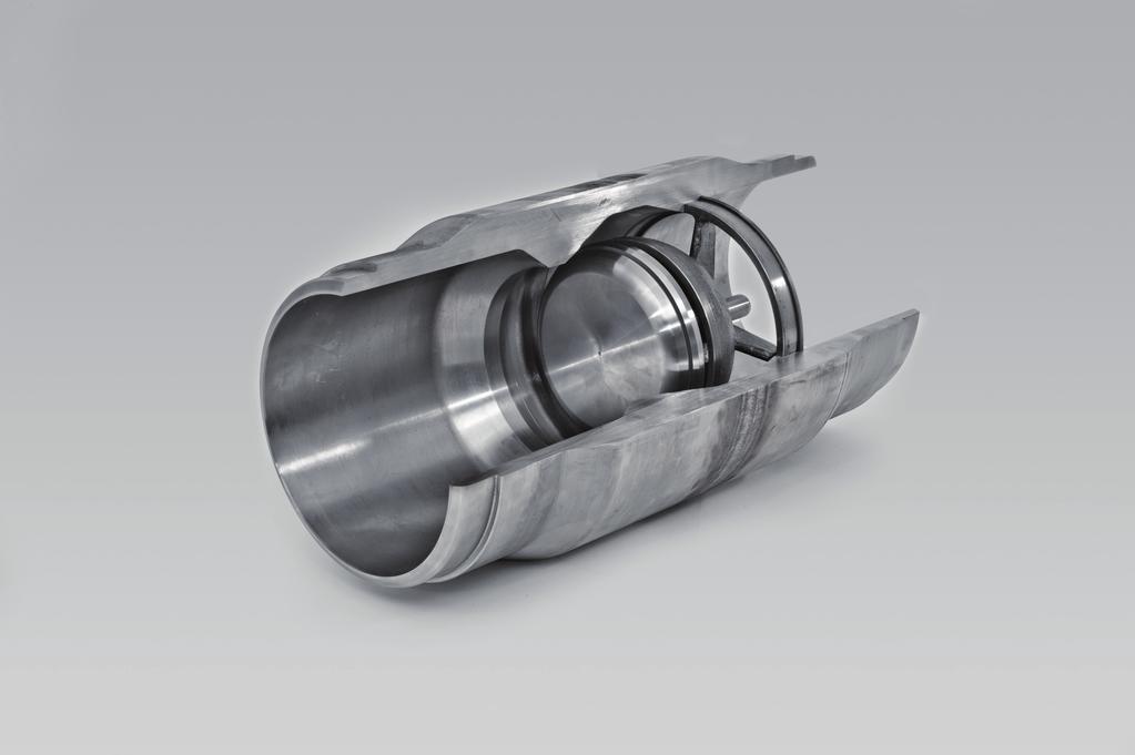
9 Description 3 Description 3.1 System overview Task Depending on the design, nozzle check valves are used to transport gaseous media in pipelines. Flange version Travel CLOSE OPEN nn002_en Fig Housing 2 Seal seat 3 Spring 4 Guide Function Flange version RV-F 5 Retaining ring 6 Sealing ring 7 Flow direction 8 Valve disk The valve disk is pressed into the seal seat ("CLOSED" position) by means of the spring force and seals it. When the flow starts, the valve disk opens until it is in "OPEN" position depending on the flow rate
10 Description / System overview Construction and design Nozzle check Valve type RV is a very compact backflow preventer that is both designed for installation in above ground and buried pipelines. The construction is based on the valve principle in which the axial spring-loaded valve disk can be moved by means of a guide and unblocks the flow section with a relatively short travel. The nozzle check valve is self-adjusting the valve reacts directly and immediately to any flow changes and in the event of a backflow closes rapidly and tightly. Type RV nozzle check valves are available with flange, weld ends for welding into the pipeline or as short pattern version. The lengths of nozzle check valves are stipulated according to API or EN depending on nominal diameter and pressure range. Special structural lengths are possible on request Sealing off the outlet The outlet is sealed off by means of the spring-loaded valve disk in the seal seat. Depending on the requirements, the sealing system can be designed to be PMSS (primary metallic, secondary soft seated) or just metal-to-metal. Both valve disk with guide and spring can be replaced Sealing out the atmosphere Due to the compact valve construction and the media-controlled functioning, none of the movable or stationary components are provided with sealings to seal out the atmosphere. An exception is the specially designed model with limit switch. In principle, repair work may only be carried out by the Franz Schuck GmbH service team or by personnel trained by Franz Schuck GmbH Actuation The nozzle check valve is operated by means of the spring-loaded valve disk depending on the flow rate of the medium. The stops for the "CLOSED" position are defined by the valve seat. Mechanical stops in the guide are also available in "OPEN" position. Depending on application and case of operation, the valve can also be equipped with special springs. i

11 Description / System overview Accessories and connections Depending on the order, the nozzle check valve can be equipped with optional accessories or with interfaces for other accessories: Drainage Ventilation End stop installation (16" and more) Identification plate All valves contain an identification plate that is attached to the housing body. Components nn009 Fig. 3-2 Specifications on the identification plate 1 CE marking 2 Key number 3 Type 4 Nominal diameter 5 Nominal pressure 6 Operating pressure 7 Operating temperature 8 Test pressure 9 Date 10 Material 11 Length 12 Order number 13 Identification number 14 Weight 15 Room for additional information
12 Assembly 4 Assembly For questions regarding assembly, please contact: Franz Schuck GmbH Daimlerstraße Steinheim GERMANY Phone +49 (7329) Fax +49 (7329) info@schuck-group.com DANGER Risk of injury from bursting components/system parts! If the permissible limit values are exceeded, the component/system can be destroyed, and as a consequence of this persons can be injured or killed! Always operate components/system parts within the permissible limit values! Danger of electric shock! DANGER Do not connect the system to power before the earth resistance and the earthing connection has been tested, examined and approved by the customer
13 Assembly CAUTION Danger of hardness increase of the steel when welding without pre-heating the weld junction at temperatures exceeding 80 C! Pre-heat the weld-on ends depending on the carbon equivalent (CEV) before starting the welding process. Observe the instructions concerning the CEV ( Page 7-3, Chapter 7.3). Make sure to monitor the temperature when pre-heating and welding! Suitable measures (such as cooling, extending the weld-on ends without coating, dismantling, etc.) must be taken to avoid elevated temperatures in areas with coated surfaces. Temperatures of up to 100 C are permissible for a short time
14 Assembly / Preparation 4.1 Preparation DANGER LIFE HAZARD from suspended loads or shifting of loads! Proceed cautiously when transporting the valve! As-delivered condition To lift the ball valve only use appropriate lifting devices as well as the designated lifting points. Never hang or raise the ball valve on drive parts or piping systems! Lifting devices, industrial trucks and load-carrying equipment and must comply with the current regulations! If no other contractual agreements have been made, the valves are supplied for transport under the following conditions: weld-on ends and mounted flange sides are coated with an anti-corrosive product the valve is in CLOSED position valve ends are sealed with PE protective caps or wooden caps to prevent the penetration of dirt and moisture the valves are packed on wooden pallets, lattice boxes or boxes Inspection Procedure 1. Check the delivery notes to make sure that the delivery is complete. 2. If there are any discrepancies, contact Franz Schuck GmbH immediately. 3. Check the delivery immediately on receipt for damage incurred during transport. In the event of damage occurring, observe the stipulations of the insurance company which, among other things, prescribe that evidence of damage is confirmed immediately by the forwarding agent. 4. If applicable, photograph damage to proof evidence
15 Assembly / Preparation Storage If possible store the valve in its original packaging. Take suitable measures to protect the valve against external influences, dirt and moisture Transport DANGER LIFE HAZARD from suspended loads or shifting of loads! Proceed cautiously when transporting the valve! Procedure To lift the valve only use the designated and marked attachment points! 1. Only use the original packaging for transporting the valve to its place of installation. The valve can be damaged by incorrect handling. 2. Only use lifting devices that are appropriate to the weight being moved. 3. Use appropriate protective materials when using steel cables or chains in order to protect the outer coating. 4. Ensure the load does not tip sideways. 5. Loads must be set upright or lifted according to the following drawings. Never use attachments or pipes! 6. When using suspension eyes, always use two eyes or more!

16 Assembly / Preparation Overview Fig Mounting 2 Lifting device 3 Lifting rope Transporting nozzle check valves 4 Suspension eye 5 Nozzle check valve 120nn
17 Assembly / Installation 4.2 Installation CAUTION Damage to the valve in the case of mechanical overloading! The nozzle check valve is not designed as fixed point/support of the pipeline. Extra support on the pipeline is required General installation instructions Unless otherwise agreed, the valve is designed to be installed in horizontal pipelines by default. Installation in vertical pipelines is also possible please specify this installation position already when ordering as the spring must be designed accordingly. Attention! Make sure the direction of installation corresponds with the flow direction arrow. The valve is provided with a flow direction arrow. The installation position must correspond with the flow direction. Flows from A to B cause the valve to open, flows in reverse direction from B to A cause the valve to close and prevent backflow! To guarantee a failure-free, low noise, non-pumping, low impact operation of the nozzle check valve in the whole operating range, a straight pipe section of at least 5 x DN must be available on both sides of the nozzle check valve. i 1 A B Fig. 4-2 Flow direction 1 Identification plate 2 Flow direction arrow 2 120nn
.")
18 Assembly / Installation Checking the installation position Prior to installation in the pipeline, the functioning of the nozzle check valve can be tested by pressing the disk towards the rear limit stop. When being released, the disk must be automatically and fully pressed into the seal seat by the spring (check according to installation position). The valve must be installed in the pipeline free from mechanical stress. If necessary, position the nozzle check valve on a suitable foundation in order to avoid any bending, torsion, pushing or tractive strain Insulating joints with flanges For delivery, the flange sealing surfaces have been provided with anti-corrosion protection. The flange sealing surfaces must be carefully cleaned before being installed in the pipeline. The flange seals and bolts must be suited for sealing strip shape, pressure, temperature and medium. The pipeline counter flanges must be aligned plane-parallel and concentrically. Retighten the screw connections crosswise and evenly with the appropriate tightening torque. Recommended tightening sequence ( Page 7-1, Fig. 7-1) 120nn007 Fig. 4-3 Nozzle check valve with flanges


19 Assembly / Installation Welding ends version For delivery, the weld ends are provided with anti-corrosion protection. The weld ends must be carefully cleaned before being welded into the pipeline. Welding must be carried out using an appropriate process and must be in accordance with all requisite instructions and requirements (test procedure, welding test, welding plan, test plan, etc.). Apply an appropriate anti-corrosion protection as soon as possible after finishing the weld seams. Fig. 4-4 Nozzle check valve with welding ends 120nn Short pattern version The frontal sealing surfaces are provided with anti-corrosion protection for delivery. These sealing surfaces must be carefully cleaned before being installed in the pipeline. All seals and bolts used to jam the valve between the pipeline surfaces must be suited for pressure, temperature and medium. Make sure that the valve surface is installed correctly and centrical to the pipeline axis. Any offset/edge between inner diameter of the valve and inner diameter of the pipeline must be avoided. Incorrect installation may result in turbulences or in an unfavorable oncoming flow as well as an increased noise development on the valve. Fig. 4-5 Short pattern nozzle check valve 120nn
20 Assembly / Installation Pipeline and flow conditions As a basic principle, nozzle check valves must be ideally suited for the flow rates of the particular area of operation. This ensures that the valves open up completely and are able to perform the assigned task reliably. CAUTION Damage/malfunction of the valve in the case of resonance vibrations! Gas flow pulsations in the lower limit range of the flow speed may result in vibrations in the valve disk and thus in malfunctions. Make sure to avoid pulsations within the medium. Do not install compressors/pumps/superchargers directly. Maximum flow rates (relating to the nominal width of the valve): gaseous media approx. 10 to max. 20 m/s liquid media approx. 2 to 5 m/s Choose the installation position of the valve in such a way that a straight pipeline section (4) that is not reduced in nominal width and that is at least 5 x DN is available on the inflow side in flow direction. Not other built-in parts (such as valves, manifolds or other fittings etc.) should be located within this flow distance Fig. 4-6 Pipeline and flow conditions 1 Compressor / pump / supercharger 2 Flow direction 5 x DN 3 Nozzle check valve 4 Pipeline section (straight) 4 120nn
21 Assembly / Installation Valve installation Prerequisite The mechanical components of the system have been tested All damage has been reported and remedied General safety instructions have been observed prior to assembly/disassembly Preparatory measures (tabular, with tool overview) have been met Direct hazard sources (electric/temperature/mechanical/crush, etc.) are excluded Procedure 1. Do not remove the packaging of the valve and the protective caps until installing the valve. 2. Carefully remove the anti-corrosion protection on the flange sealing surfaces or the weld-on ends using appropriate means. 3. Examine the pipelines for contamination and foreign particles before installation, and clean if necessary. 4. Ensure that no contamination or foreign body can enter the pipeline or the valve during assembly work. 5. Install the valve into the pipeline in CLOSED position. 6. Install the valve into the pipeline as stress-free as possible. External tractive, compressive or bending forces must be avoided or reduced to a minimum using suitable measures (such as erecting a foundation). 7. Ensure that inner and outer coating are not damaged during installation
22 Assembly / Testing 4.3 Testing Function test Functioning and operation of the nozzle check valve must be tested again prior to installation. To do so, slightly press the valve disk by hand against the spring tension into the "OPEN" position ( Page 4-6, Chapter 4.2.1). The valve is ready for operation on completion of the installation. When the flow starts and the contact pressure is about 0.1 bar, the valve opens and releases the flow. The valve closes when the flow rate decreases
23 Operation 5 Operation 5.1 Safety instructions for operation Comply with the safety instructions and protective measures specified in chapter 2 as well as the applicable legal regulations. i DANGER Risk of injury from bursting components/system parts! If the permissible limit values are exceeded, the component/system can be destroyed, and as a consequence of this persons can be injured or killed! Always operate components/system parts within the permissible limit values! CAUTION Incorrect operation of the valve can lead to damages or function changes! Carry out all operational steps carefully. 5.2 Operation Observe the maximum permissible operating conditions specified on the identification plate to ensure correct operation ( Page 3-3, 3.1.6). Installation position and ideal flow conditions are essential for correct functioning
24 Maintenance 6 Maintenance CAUTION Dangers to health and safety of operating and maintenance personnel. Dangers to the environment. Personnel can be harmed by external energy or stored energy. Escaping gaseous or liquid media can be harmful to personnel and the environment. Life hazard in the case of escaping sour gas or sulphinic lye! The safety instructions must be unconditionally observed! For support in maintenance and optimization work, we recommend you contact the Franz Schuck GmbH service department. Franz Schuck GmbH Daimlerstraße Steinheim GERMANY Phone +49 (7329) Fax +49 (7329) info@schuck-group.com
25 Maintenance / Inspection/Maintenance 6.1 Inspection/Maintenance Regular maintenance Schuck nozzle check valves type RV are maintenance-free Recommended inspection and maintenance intervals Component Ongoing Annually Check valve type RV in plant construction Functional check (open closed) x Leak test x Pressure loss measurement x Other checks External leakage x Damage x Noises x Tab. 6-1 Recommended inspection and maintenance intervals Ventilation/drainage (optional) CAUTION Dangers to health and safety of operating and maintenance personnel. During the venting and discharge/drainage procedures, medium can escape under high pressure and with a considerable noise. Note the blow-out direction! Avoid contact with medium! Wear ear protection!
26 Maintenance / Inspection/Maintenance Faults and troubleshooting Fault Cause Remedy Leakage in disk Contaminations in the seat area Clean seat area and valve disk, purge with temporarily increased speed if applicable. Valve disk damaged Replace valve disk. High pressure loss Deposits on the valve disk Open valve several times until it is smooth-running again, or remove and clean valve disk and bearings. Foreign matter between valve disk and housing seat Remove foreign substances manually, purge with temporarily increased speed if applicable. Valve blocked Considerable noise level (water hammer) Foreign particles jammed in the seating area Speed of flowing medium too high Pressure of medium too high Increase flow rate and try to purge the foreign matter. Check operating conditions and installation position. Incorrect installation position Valve installed incorrectly, contrary to the required mounting direction or unfavorable installation conditions Functioning of the spring affected Pump/supercharger/ compressor transports against the closed valve Flow arrow has not been observed during installation Clean spring. If medium is contaminated, use spring gaiter. Remove valve and reinstall into pipeline in correct flow direction. Tab. 6-2 Faults and troubleshooting
27 Maintenance / Repairs 6.2 Repairs In principle, repair work may only be carried out by the Franz Schuck GmbH service team or by personnel trained by Franz Schuck. This is the only way to ensure that repairs are carried out correctly using original spare parts. This will maintain the validity of the warranty. i Observe the following instructions: If faults occur, immediately notify the Schuck service personnel in charge and take appropriate measures Do not carry out work on pressurized systems, do not open the equipment De-pressurize system before starting work Do not remove any components during operation Display warning signs that refer to the risks involved if the system is started up unintentionally or if the electricity or line pressure is switched on If there is damage or a defect, switch off the affected equipment and systems In the case of damage of any kind, stop work on the affected equipment and systems After completion of work, check for correct function and if appropriate fulfill and comply with all technical guidelines Check that the optionally mounted accessories are functioning correctly
28 Appendix 7 Appendix 7.1 Tightening sequence for flange bolts The bolt numbers represent the order in which they should be tightened. 1 4-Hole Flange Hole Flange Hole Flange Hole Flange Hole Flange Fig Hole Flange Tightening sequence for flange bolts Hole Flange nn010_en
29 Appendix / Conversion factors 7.2 Conversion factors Value Unit Conversion unit Factor Length mm in in mm 25.4 m ft ft m Weight kg lb lb kg Pressure bar psi psi bar MPa psi psi MPa Temperature bar MPa 0.1 MPa bar 10 C F 1.8 C + 32 F C ( F 32) Volume cm 3 in 3 (cubic inch) in 3 (cubic inch) cm Tab. 7-1 Conversion factors
30 Appendix / Calculation formula to determine the carbon equivalent (CEV) 7.3 Calculation formula to determine the carbon equivalent (CEV) To avoid an increased hardness in the weld junctions during welding, it is required to pre-heat the weld-on ends depending among others on the carbon equivalent Calculation formula (standard) The calculation formula applies for steels of the following consistency: Carbon C: up to 0.22% Manganese Mn: up to 1.6% Chromium Cr: up to 1.0% Nickel Ni: up to 3.5% Molybdenum Mo: up to 0.6% Copper Cu: up to 1.0% The calculation formula for steels of the above-mentioned consistency is: CEV = C + % Mo 4 + % Cr 5 + % Mn 6 + % Ni 15 + % P 2 + % Si 4 + % V 5 + % Cu 13 % Carbon Equivalent Fig. 7-2 Steel consistency and the resulting calculation formula Adjust the pre-heat temperature on an individual basis depending on carbon equivalent, welding consumable, product gauge, hydrogen content and heat input in compliance with the welding supervisor. The following temperature is recommended after determining the CEV value: CEV [%] 0.45 up to 100 C Recommended temperature for pre-heating [ C] i C Tab. 7-2 Recommended temperature for pre-heating Calculation formula for steels with different consistencies When using steels outside the above-mentioned consistency, adjust the heat input in compliance with the welding supervisor on an individual basis
31 Appendix / Marking of packages 7.4 Marking of packages Marking of packages according to DIN and ISO R 780 Overview Marking of packages according to DIN and ISO R 780 Electrostatic sensitive device Do NOT use fork lift truck here Sling here Tear off here Use no hooks Clamp here This way up Centre of gravity Do not destroy barrier NO hand truck here Protect from heat and radioactive sources Keep dry Keep away from heat Fragile, Handle with care Stacking limitation Temperature limitations Tab. 7-3 Marking of packages according to DIN and ISO R
32 Appendix / Marking of packages Schuck symbols transporting and unpacking packages Overview Schuck symbols transporting and unpacking packages Use edge protectors Do not use chains Do not destroy pipes Tab. 7-4 Schuck symbols transporting and unpacking packages
33 SCHUCK FREE SPACE Room for your notes
34 EN MAR90033 SCHUCK GROUP Franz Schuck GmbH Daimlerstraße Steinheim, Germany Fon +49. (0) Fax +49. (0) info@schuck-group.com We manufacture and distribute components for connecting pipeline systems in more than 50 countries, with 5 international offices and over 40 years of experience. Do you want to find out more about a specific product? Give us a call, or visit to our website at
Measurement accessories METPOINT OCV for the measurement in systems up to 40 bar
 EN - english Instructions for installation and operation Measurement accessories METPOINT OCV for the measurement in systems up to 40 bar Dear customer, Thank you for deciding in favour of the METPOINT
Wafer Check Valve. Contents. User s Manual. (1) Be sure to read the following description of our product warranty 1
 Be sure to read the following description of our product warranty 1") Serial No. H-V066-E-3 Wafer Check Valve User s Manual Contents (1) Be sure to read the following description of our product warranty 1 (2) General operating instructions 2 (3) General instructions for
Serial No. H-V066-E-3 Wafer Check Valve User s Manual Contents (1) Be sure to read the following description of our product warranty 1 (2) General operating instructions 2 (3) General instructions for
Declaration of Conformity as per Directive 97/23/EC
 Declaration of Conformity as per Directive 97/23/EC The manufacturer declares that:, 47906 Kempen, Germany Discontinous, inline sampling valves Series 27a and Series 27g, with packing with lever (180 )
Declaration of Conformity as per Directive 97/23/EC
 Declaration of Conformity as per Directive 97/23/EC The manufacturer declares that:, 47906 Kempen, Germany Continuous, inline sampling valves Series 27f, with packing Operate with either; Star lever, or
Declaration of Conformity as per Directive 97/23/EC and Manufacturer s Declaration as per Directive 98/37/EC
 Declaration of Conformity as per Directive 97/23/EC and Manufacturer s Declaration as per Directive 98/37/EC The manufacturer declares that:, 47906 Kempen, Germany Continuous, PFA-lined, inline sampling
Instruction manual. for. high purity gas pigtails 200 bar / 300 bar
 Instruction manual for high purity gas pigtails 200 bar / 300 bar Contents Contents... 2 1. Preface... 3 1.1 Overview... 3 1.2 General... 3 1.3 Intended use... 4 1.4 Personnel requirements... 4 2. For
Flowmeter. Original operating manual DFM
 Flowmeter Original operating manual Series DFM 165 350 Version BA-2016.08.09 EN Print-No. 300 458 TR MA DE Rev002 ASV Stübbe GmbH & Co. KG Hollwieser Straße 5 32602 Vlotho Germany Phone: +49 (0) 5733-799-0
Type BBS-03, BBS-05, BBS-06, BBS-25
 Type BBS-03, BBS-05, BBS-06, BBS-25 Sterile connection elements Sterile Verbindungselemente Raccords union stériles Operating Instructions Bedienungsanleitung Manuel d utilisation 1. THE OPERATING INSTRUCTIONS
Mounting and Operating Instructions EB 3007 EN. Self-operated Pressure Regulators. Differential Pressure Regulators (opening) Type Type 42-25
 Type Type 42-25") Self-operated Pressure Regulators Differential Pressure Regulators (opening) Type 42-20 Type 42-25 Type 42-20 Differential Pressure Regulator Type 42-25 Differential Pressure Regulator Mounting and Operating
Self-operated Pressure Regulators Differential Pressure Regulators (opening) Type 42-20 Type 42-25 Type 42-20 Differential Pressure Regulator Type 42-25 Differential Pressure Regulator Mounting and Operating
Declaration of Conformity as per Directive 97/23/EC
 Declaration of Conformity as per Directive 97/23/EC The manufacturer declares that:, 47906 Kempen, Germany Multi-way diverting valves Series 29a and Series 29b, with packing with lever 1. The valves are
Translation of the original Operating Instructions for HKS rubber compensators
 Because of their flexible elements and mechanisms, HKS rubber compensators are susceptible to damage of all types and adverse loads in operation. For reliable operation of a compensator and, thus, the
Type 3709 Pneumatic Lock-up Valve. Translation of original instructions. Mounting and Operating Instructions EB 8391 EN
 Type 3709 Pneumatic Lock-up Valve Translation of original instructions Mounting and Operating Instructions EB 8391 EN Edition July 2017 Note on these mounting and operating instructions These mounting
Operating Instructions in compliance with Pressure Equipment Directive 2014/68/EU. FAS Brass Check Valve RDL
 Operating Instructions in compliance with Pressure Equipment Directive 2014/68/EU FAS Brass Check Valve RDL Please read these operating instructions carefully to ensure a safe operation and keep the same
Non-Return Valve SRK 22A
 Non-Return Valve SRK 22A Original Installation Instructions 819238-02 Contents Foreword... 3 Availability... 3 Formatting features in the document... 3 Safety... 3 Use for the intended purpose... 3 Basic
Pressure relief valve
 Pressure relief valve Operating manual Series DHV 718 Version BA-2016.01.11 EN Print-No. 300 524 TR MA DE Rev001 ASV Stübbe GmbH & Co. KG Hollwieser Straße 5 32602 Vlotho Germany Phone: +49 (0) 5733-799-0
Installation, Operating and Maintenance Manual Overflow Regulator Type 94/ 94 E
 Installation, Operating and Maintenance Manual Overflow Regulator Type 94/ 94 E Table of content 1. General information on installation, operating and maintenance instructions 1.1 Hazard notices 1.2 Qualified
Pressure relief valve
 Pressure relief valve Operating manual Series DHV 712 R Version BA-2016.01.19 EN Print-No. 300 472 TR MA DE Rev001 ASV Stübbe GmbH & Co. KG Hollwieser Straße 5 32602 Vlotho Germany Phone: +49 (0) 5733-799-0
Spilt body Flange ball valve. TC-205MFF-PN1640 User Manual English Version. Document No: TC-205MFF-PN1640.Ur-manual. Date: 2007/04/2617. Version: 1.
 Spilt body Flange ball valve TC-205MFF-PN1640 Series PED Category I,II TC-205MFF-PN1640 User Manual English Version Use for company in Europe who will place the product on the market, please amend which
Ball valve HKSF-W100. Ball valve HKSF-W100. RMA Kehl GmbH & Co. KG Oststrasse 17 D Kehl / Germany
 Ball valve HKSF-W100 RMA Kehl GmbH & Co. KG Oststrasse 17 D-77694 Kehl / Germany info@rma-kehl.de www.rma-armaturen.de 1 Design Features: RMA-ball valves type HKSF-W are fully welded and completely maintenance-free
Mounting and Operating Instructions EB 2558 EN. Self-operated Pressure Regulators. Type Pressure Build-up Regulator
 Self-operated Pressure Regulators Type 2357-31 Pressure Build-up Regulator with safety function and integrated excess pressure valve Type 2357-31 with non-return unit at port C Ports A and B with soldering
Needle valve. Contents. User s Manual. (1) Be sure to read the following warranty clauses of our product 1. (2) General operating instructions 2
 Be sure to read the following warranty clauses of our product 1. (2) General operating instructions 2") Serial No. H-V024-E-7 Needle valve User s Manual Contents (1) Be sure to read the following warranty clauses of our product 1 (2) General operating instructions 2 (3) General instructions for transportation,
Serial No. H-V024-E-7 Needle valve User s Manual Contents (1) Be sure to read the following warranty clauses of our product 1 (2) General operating instructions 2 (3) General instructions for transportation,
Mounting and Operating Instructions EB 3009 EN. Self-operated Regulators. Type RS Check Valve (backflow protection)
") Self-operated Regulators Type 42-10 RS Check Valve (backflow protection) Type 42-10 RS Check Valve (backflow protection) Mounting and Operating Instructions EB 3009 EN Edition December 2015 Definition
Self-operated Regulators Type 42-10 RS Check Valve (backflow protection) Type 42-10 RS Check Valve (backflow protection) Mounting and Operating Instructions EB 3009 EN Edition December 2015 Definition
Mounting and Operating Instructions EB 3007 EN. Self-operated Pressure Regulators. Type Type Differential Pressure Regulators (opening)
") Self-operated Pressure Regulators Type 42-20 Type 42-25 Differential Pressure Regulators (opening) Translation of original instructions Type 42-20 Differential Pressure Regulator Type 42-25 Differential
Self-operated Pressure Regulators Type 42-20 Type 42-25 Differential Pressure Regulators (opening) Translation of original instructions Type 42-20 Differential Pressure Regulator Type 42-25 Differential
Installation & Operation Manual Proven Quality since 1892
 Content 1. ERIKS operating companies 2. Product description 3. Requirements for maintenance staff 4. Transport and storage 5. Function 6. Application 7. Installation 8. Maintenance 9. Service and repair
Pressure maintenance valve SDV-P / SDV-P-E
 Translation of the original manual Pressure maintenance valve SDV-P / SDV-P-E Assembly and Operating Manual Superior Clamping and Gripping Imprint Imprint Copyright: This manual remains the copyrighted
Safety. Operating instructions Solenoid valve for gas VG 6 VG 15/10 DANGER. Contents WARNING CAUTION. Changes to edition 09.14
 15 Elster GmbH Edition 7.15 Translation from the German 519 D F NL I E DK S N P GR TR CZ PL RUS H www.docuthek.com Operating instructions Solenoid valve for gas VG VG 15/1 Contents Solenoid valve for gas
Mounting and Operating Instructions EB 3017 EN. Self-operated Regulators
 Self-operated Regulars Flow and Differential Pressure Regular Type 42-37 Flow and Differential Pressure or Flow and Pressure Regular Type 42-39 Type 42-37 Type 42-39 Fig. 1 Flow and differential pressure
Mounting and Operating Instructions EB EN. Self-operated Pressure Regulators. Type 2335 Excess Pressure Valve with pilot valve
 Self-operated Pressure Regulators Type 2335 Excess Pressure Valve with pilot valve Type 2335 Excess Pressure Valve Mounting and Operating Instructions EB 2552-2 EN Edition January 2016 Definition of signal
KTM OM-2 SPLIT BODY FLOATING BALL VALVES INSTALLATION AND MAINTENANCE INSTRUCTIONS
 Before installation these instructions must be fully read and understood SECTION 1 - STORAGE 1.1 Preparation and preservation for storage All valves should be properly packed in order to protect the parts
Mounting and operating instructions EB 2530 EN. Self-operated Pressure Regulator. Pressure Reducing Valve Type M 44-2
 Self-operated Pressure Regulator Pressure Reducing Valve Type M 44-2 Type M 44-2, connection G 1 4, K VS = 0.15 Type M 44-2, connection G 1, K VS = 6 Fig. 1 Type M 44-2 Pressure Reducing Valve Mounting
INSTALLATION COMMISSIONING, OPERATION & MAINTENANCE MANUAL
 WedgeRock RW Series Worm Gear Actuators INSTALLATION COMMISSIONING, OPERATION & MAINTENANCE MANUAL Revision 01 Date 4/3/17 Page 1 Table of Contents 1.0 INTRODUCTION... 4 1.1 PURPOSE... 4 1.2 AUDIENCE...
Operating Instructions. Ball valve fitting according to ZB For pressure transmitter VEGABAR 82. Document ID: 50027
 Operating Instructions Ball valve fitting according to ZB 2553 For pressure transmitter VEGABAR 82 Document ID: 50027 Contents Contents 1 About this document 1.1 Function... 3 1.2 Target group... 3 1.3
Operating and maintenance manual Filter and reducing station Series / 1.0
 Operating and maintenance manual Filter and reducing station Series 961 04.2017 / 1.0 Original instructions ARCA Regler GmbH. All rights reserved. Cover picture background: Freepik.com ARCA Regler GmbH
Differential Pressure Regulator Type Type 45-6 (0.1 to 1 bar, DN 15) Mounting and Operating Instructions EB 3226 EN
 Mounting and Operating Instructions EB 3226 EN") Differential Pressure Regulator Type 45-6 Type 45-6 (0.1 to 1 bar, DN 15) Mounting and Operating Instructions EB 3226 EN Edition March 2008 Contents Contents Page 1 Design and principle of operation...................
Differential Pressure Regulator Type 45-6 Type 45-6 (0.1 to 1 bar, DN 15) Mounting and Operating Instructions EB 3226 EN Edition March 2008 Contents Contents Page 1 Design and principle of operation...................
Siphon vessel / Priming aid
 Manufacturer: sera GmbH sera-straße 1 34376 Immenhausen Germany Tel.: +49 5673 999-00 Fax: +49 5673 999-01 info@sera-web.com Keep the operating manual for future use! Record the exact type and serial number
Pneumatic switch module 3/2-way valve (On/Off) Types P Types FP Function tested for use of the float in Ex-zone 0
 Types P Types FP Function tested for use of the float in Ex-zone 0") Operating Manual LTIA3E Pneumatic switch module 3/2-way valve (On/Off) Types P Types FP Function tested for use of the float in Ex-zone 0 Contents 1. Safety Instructions 2. Conformity to standards 3. Technical
Operating Manual LTIA3E Pneumatic switch module 3/2-way valve (On/Off) Types P Types FP Function tested for use of the float in Ex-zone 0 Contents 1. Safety Instructions 2. Conformity to standards 3. Technical
GI Series Diaphragm Pressure Gauge Guard
 Diaphragm Pressure Gauge Guard INSTRUCTION MANUAL Please read this Instruction Manual Carefully and Thoroughly for the Correct and Optimum use of this Product. Kindly keep this manual in a convenient place
Modular valve block. Operating manual Series MVB 100/200. Version BA EN Print-No TR MA DE Rev001
 Modular valve block Operating manual Series MVB 100/200 Version BA-2016.04.20 EN Print-No. 300 627 TR MA DE Rev001 ASV Stübbe GmbH & Co. KG Hollwieser Straße 5 32602 Vlotho Germany Phone: +49 (0) 5733-799-0
KBV21i and KBV40i Key Operated Boiler Blowdown Valves Installation and Maintenance Instructions
 4059051/3 IM-P405-48 EMM Issue 3 KBV21i and KBV40i Key Operated Boiler Blowdown Valves Installation and Maintenance Instructions 1. Safety information 2. General product information 3. Installation 4.
Type Operating Instructions. 2/2-way solenoid valve 2/2-Wege Magnetventil Electrovanne 2/2 voies.
 2/2-way solenoid valve 2/2-Wege Magnetventil Electrovanne 2/2 voies We reserve the right to make technical changes without notice. Technische Änderungen vorbehalten. Sous réserve de modifications techniques.
Manual Actuated Boiler Blowdown Valves
 Manual Actuated Boiler Blowdown Valves Installation and Maintenance Instructions 1. Safety information 2. General product information 3. Installation 4. Operation 5. Maintenance 6. Spare parts p.1 1. Safety
Instruction Manual Contact Pressure Vacuum Gauge
 MS10 Instruction Manual Contact Pressure Vacuum Gauge Table of Contents 1. Safety Instructions 2. Intended Applications 3. Product Description and Functions 4. Installation 5. Commissioning 6. Maintenance
Ball valve. Operating instructions for series. Version BA Print-No TR MA DE Rev001
 Ball valve Operating instructions for series Version BA-2016.02.05 Print-No. 300 587 TR MA DE Rev001 We reserve the right to make technical changes. Read carefully before use. Save for future use. ASV
PV4 and PV6 Piston Valves
 1181250/1 IM-P118-05 ST Issue 1 PV4 and PV6 Piston Valves Installation and Maintenance Instructions 1. Safety information 2. General product information 3. Installation 4. Commissioning 5. Operation 6.
S1, S2, S3, S5, S6, S7, S8, S12 and S13 Separators Installation and Maintenance Instructions
 PREVIOUS REFERENCE NO. IMP02355 0231150/13 IMF0501ENISS2 CMGT S1, S2, S3, S5, S6, S7, S8, S12 and S13 Separators Installation and Maintenance Instructions 1. Safety information 2. General product information
Type 2000 INOX. Quickstart. English Deutsch Français. 2/2-way angle seat valve 2/2-Wege Schrägsitzventil Vanne à siège incliné 2/2 voies
 Type 2000 INOX 2/2-way angle seat valve 2/2-Wege Schrägsitzventil Vanne à siège incliné 2/2 voies Quickstart English Deutsch Français Contents 1 QUICKSTART... 2 2 CONTACT ADDRESS... 2 3 INTENDED USE...
Pneumatic proportional controller Types M Types FM Function tested for use of the float in Ex-zone 0
 Operating Manual LTIA5E Pneumatic proportional controller Types M Types FM Function tested for use of the float in Ex-zone 0 Contents 1. Safety Instructions 2. Conformity to standards 3. Technical data
Swing Check Valve CB 14 CB 24S CB 26 CB 26A
 Swing Check Valve CB 14 CB 24S CB 26 CB 26A Original Installation Instructions 810707-04 Contents Foreword... 3 Availability... 3 Formatting features in the document... 3 Safety... 3 Use for the intended
3-PIECE BALL VALVE, 3600 PSI/ PN 248, WITH ISO DIRECT MOUNTING PAD 306M SERIES/ PED Category II
 3-PIECE BALL VALVE, 3600 PSI/ PN 248, WITH ISO DIRECT MOUNTING PAD 306M SERIES/ PED Category II 306M User Manual English Version Use for company in Europe who will place the product on the market, please
USER MANUAL. 1. Principle of operation. 2. Delivery condition. SPRING-LOADED SAFETY VALVES zarmak. Edition: 07/2016 Date: V (ex.
 ZETKAMA Sp. z o.o. ul. 3 Maja 12 PL 57-410 Ścinawka Średnia SPRING-LOADED SAFETY VALVES zarmak USER MANUAL 782V (ex. 782) Edition: 07/2016 Date: 01.07.2016 TABLE OF CONTENTS 1. Principle of operation 2.
for the of and the EM55-1
 Operating Manua al for the Tapping Points of the EM55-1/EM55-2/EM55-3/ /EM55-4 series and the EE55-1/EE55-2/EE55-3/EE55-4 series EM55-1 Contents Contents... 2 1. Introduction... 3 1.1 General... 3 1.2
Installation, Operating and Maintenance Instructions. V914 Cast Iron Flanged Swing Check Valve V914
 Installation, Operating and Maintenance Instructions V914 Cast Iron Flanged Swing Check Valve V914 THE PRESSURE EQUIPMENT DIRECTIVE 97/23/EC and CE MARKING The Pressure Equipment Regulations 1999 (SI 1999/2001)
Operating Instruction English. Revision A Date author NH This operating instruction is not subject to updating. Airgun
 Revision A Date 23.11.2012 author NH This operating instruction is not subject to updating Airgun 95400 1 This airgun is a quality product with special focus on high functionality, easy handling, safety
Inverted Bucket Steam Trap IB 16A-7
 Inverted Bucket Steam Trap IB 16A-7 Original Installation Instructions 819114-02 Contents Preface... 3 Availability... 3 Text layout... 3 Safety... 3 Usage for the intended purpose... 3 Basic safety notes...
KBV21i and KBV40i Air Actuated Boiler Blowdown Valves
 4059051/1 IM-P405-48 AB Issue 1 KBV21i and KBV40i Air Actuated Boiler Blowdown Valves Installation and Maintenance Instructions 1. Safety information 2. General product information 3. Installation 4. Commissioning
Operating instruction
 Operating instruction MV, XV, HG, HP, RKO, D2G, TV, BV, WB & SLV 1 Introduction 2 2 Stafsjö s knife gate valves 2 3 Technical information 2 3.1 Pressure test 2 3.2 Labelling 2 4 Storage 3 5 Transportation
Installation and operating manual. Pneumatic control station LK product no: PCS 1-10
 LK product no: PCS 1-10 Article no: 74503 Revision:8 Article no: 74503 Revision: 8 2 (23) Contents 1. General information... 5 2. Safety precautions... 5 2.1 Significance of symbols... 5 2.2 Explanatory
OPERATING MANUAL CHEMTRAC 840M MANUAL RETRACTABLE PROCESS HOLDER
 OPERATING MANUAL CHEMTRAC 840M MANUAL RETRACTABLE PROCESS HOLDER Table of contents 1 Security and safety measures... 5 1.1 General safety instructions... 5 1.2 Intended use... 5 1.3 Danger zones and residual
Installation, operation & maintenance manual - original version
 Installation, operation & maintenance manual - original version AVK gate valves for water and wastewater Series 01, 02, 06, 12, 15, 18, 20, 26, 32, 33, 36, 38, 50, 55 and 636 COPYRIGHT AVK GROUP A/S 2018
M45 ISO Ball Valve DN25 to 150 Installation and Maintenance Instructions
 BAC 13310 IM-P133-42 ST Issue 2 M45 ISO Ball Valve DN25 to 150 Installation and Maintenance Instructions 1. General safety information 2. General product information 3. Installation 4. Commissioning 5.
MAINTENANCE AND OPERATING MANUAL
 MAINTENANCE AND OPERATING MANUAL Cyclone condensate separator Type ASA EN EN Maintenance and operating manual Purpose and appropriate use Dear Customer, thank you for choosing our product. In order to
Operating Instructions in compliance with Pressure Equipment Directive 2014/68/EU. FAS Manual Brass Shut-Off Valve DN10 through DN22
 Operating Instructions in compliance with Pressure Equipment Directive 2014/68/EU FAS Manual Brass Shut-Off Valve DN10 through DN22 Please read these operating instructions carefully to ensure a safe operation
Instructions for Installation, Operating and Maintenance
 Instructions for Installation, Operating and Maintenance for ABO butterfly valves series 500 1) Introduction 2) Safety Instructions 3) Valve Identification 4) Transportation and Storage 5) Installation
TP1 and TP2 Temporary Cone Shaped Strainers
 1698051/2 IM-P169-07 ST Issue 2 TP1 and TP2 Temporary Cone Shaped Strainers Installation and Maintenance Instructions TP1 1. Safety information 2. General product information 3. Installation and commissioning
BGA158 Series CE Approved Class A Shutoff Gas Valve
 Installation Instructions BGA158 Issue Date August 24, 2011 BGA158 Series CE Approved Class A Shutoff Gas Valve Applications The BGA158 Series shutoff gas valve is an electrically operated gas valve that
TITAN FLOW CONTROL, INC.
 PREFACE: This manual contains information concerning the installation, operation, and maintenance of Titan Flow Control (Titan FCI) Simplex Basket Strainers. To ensure efficient and safe operation of Titan
USM21 Sealed Bimetallic Steam Trap for use with Pipeline Connectors Installation and Maintenance Instructions
 6250250/1 IM-P625-03 ST Issue 1 USM21 Sealed Bimetallic Steam Trap for use with Pipeline Connectors Installation and Maintenance Instructions 1. General safety information 2. General product information
Installation, Operating & Maintenance Instructions. All-metal gate valve with extended pneumatic actuator. Series 48 DN mm (I.D.
 Installation, Operating & Maintenance Instructions All-metal gate valve with extended pneumatic actuator Series 48 DN 16 320 mm (I.D. ⅝" 12") This manual is valid for the following product ordering numbers:
Dual Solenoid Gas Valve Installation
 Installation IMPORTANT: These instructions are intended as a guide for qualified personnel installing or servicing FLYNN Gas Products. Carefully follow all instructions in this bulletin and all instructions
Operating Manual VSA100A. tina29e1 ( )
") Operating Manual Incl. EU Declaration of Conformity Vacuum Switch VSA100A tina29e1 (2017-05) 1 Product Identification In all communications with INFICON, please specify the information on the product nameplate.
Operating Manual Incl. EU Declaration of Conformity Vacuum Switch VSA100A tina29e1 (2017-05) 1 Product Identification In all communications with INFICON, please specify the information on the product nameplate.
Operating Instructions SKYJET Compact Sub-distributor
 Operating Instructions SKYJET Compact Sub-distributor INDEX Page 1. General... 2 2. Safety... 2 4 A. Distributor Type... 5 B. Number of Outlets... 5 C. Revision... 6 D. Accessories... 6 3. Application...
Installation, Operating & Maintenance Instructions. Variable leak valve with manual actuator. Series 590 DN 16 mm (I. D. ⅝") E
 E") Installation, Operating & Maintenance Instructions Variable leak valve with manual actuator DN 16 mm (I. D. ⅝") This manual is valid for the following product ordering numbers: 59024-. E01 -... Sample
Installation, Operating & Maintenance Instructions Variable leak valve with manual actuator DN 16 mm (I. D. ⅝") This manual is valid for the following product ordering numbers: 59024-. E01 -... Sample
Steam trap BK 37 BK 28 BK 29 BK 37 ASME BK 28 ASME BK 29 ASME
 Steam trap BK 37 BK 28 BK 29 BK 37 ASME BK 28 ASME BK 29 ASME Original Installation Instructions 818689-05 Contents Foreword... 3 Availability... 3 Formatting features in the document... 3 Safety... 3
Operating Instructions in compliance with Pressure Equipment Directive 2014/68/EU. FAS Straight-Way Valve with Packing Gland
 Operating Instructions in compliance with Pressure Equipment Directive 2014/68/EU FAS Straight-Way Valve with Packing Gland Please read these operating instructions carefully to ensure a safe operation
SCA Series Inverted Bucket Steam Traps
 0770050/5 IM-P077-06 ST Issue 5 SCA Series Inverted Bucket Steam Traps Installation and Maintenance Instructions 1. General safety information 2. General product information 3. Installation 4. Commissioning
Installation and Maintenance Instruction Manual
 Installation and Maintenance Instruction Manual Bi-metal Thermometer Model A and E in a configuration - pursuant to ASME B40.200: ##=E#=### or ##=ERT#=### - pursuant to EN 13190: ###=A#=### or ##=ART#=###
DCV1, DCV3 and DCV3LT Disc Check Valves Installation and Maintenance Instructions
 1340050/7 IM-P134-07 CMGT Issue 7 DCV1, DCV3 and DCV3LT Disc Check Valves Installation and Maintenance Instructions 1. Safety information 2. General product information 3. Installation 4. Commissioning
Mounting and Operating Instructions EB 2555 EN. Self-operated Pressure Regulators. Pressure Reducing Valves Type 50 ES Type 50 EM.
 Self-operated Pressure Regulators Pressure Reducing Valves Type 50 ES Type 50 EM Type 50 ES Type 50 EM Fig. 1 Pressure reducing valves Mounting and Operating Instructions EB 2555 EN Edition November 2011
RARS5000 AIR BODY SAW OWNER S OPERATING MANUAL
 RARS5000 AIR BODY SAW OWNER S OPERATING MANUAL DESCRIPTION 1. No mar 2. No mar tip 3. Housing grip 4. Trigger 5. Air inlet 6. Air inlet plug 7. Plastic board Important! It is essential that you read the
Safety Please read and keep in a safe place Operating instructions Linear flow control VFC Linear flow control with actuator IFC
 05 Elster GmbH Edition 0.5 Translation from the German 058 D F NL I E DK S N P GR TR CZ PL RUS H www.docuthek.com Operating instructions Linear flow control VFC Linear flow control with actuator IFC Contents
Operating Instructions - Rescue Equipment. RAM Support LRS-T EN Edition (translation of the original operating instructions)
") Operating Instructions - Rescue Equipment RAM Support LRS-T 174190085 EN Edition 08.2017 (translation of the original operating instructions) Content Page 1. Hazard classes 3 2. Product safety 4 3. Intended
Operating Instructions - Rescue Equipment RAM Support LRS-T 174190085 EN Edition 08.2017 (translation of the original operating instructions) Content Page 1. Hazard classes 3 2. Product safety 4 3. Intended
CAST IRON SAFETY VALVE TYPE 6301
 CHARACTERISTICS The 6301 safety valve is dedicated to protect the equipment from potential overpressure. This is an automatic device that closes when the pressure conditions are back to normal. It is a
Contents. Operating instructions. Pressure switch, heavy-duty version Model PSM-520
 Operating instructions Contents EN Pressure switch, heavy-duty version Model PSM-520 1. General information 2. Design and function 3. Safety 4. Transport, packaging and storage 5. Commissioning, operation
Magnetic level switch type MR783 Instruction Manual
 Magnetic level switch Magnetic level switch type MR783 1. DESCRIPTION page 3 1.1 Operation page 3 1.2 Application page 3 1.3 Description page 3 2. SPECIFICATIONS page 3 2.1 Service Conditions page 4 2.2
Airfix D-E-B Installation and operating instructions
 www.flamco.nt-rt.ru Airfix D-E-B Installation and operating instructions Dear Customer, With the Airfix D-E-B membrane expansion vessel you have acquired a Flamco quality product. This expansion vessel
Spiratec ST14, ST16 and ST17 Sensor Chambers and sensors
 0862050/1 IM-P086-18 MI Issue 1 Spiratec ST14, ST16 and ST17 Sensor Chambers and sensors Installation and Maintenance Instructions 1. Safety Information 2. General product information 3. Installation 4.
Telefon (+45) Telefax (+45)
 Telefax (+45)") Uni-Valve A /S VENTILER & INSTRUMENTER Telefon (+45) 43 43 82 00 Telefax (+45) 43 43 74 75 mail@uni-valve.com www.uni-valve.com UNI-S83 / S84 3/4-way ball valve Installation and Operating manual 3/4-WAY
Uni-Valve A /S VENTILER & INSTRUMENTER Telefon (+45) 43 43 82 00 Telefax (+45) 43 43 74 75 mail@uni-valve.com www.uni-valve.com UNI-S83 / S84 3/4-way ball valve Installation and Operating manual 3/4-WAY
OPERATING INSTRUCTIONS (Translation) Rope Winch Type , , ,75
 Rope Winch Type , , ,75") OPERATING INSTRUCTIONS (Translation) Rope Winch Type 4202.0,5 4585.0,5 4585.0,75 GB The length of the rope is correct if: 1. User groups Duties Operator Operation, visual inspection Specialist Assembly,
OPERATING INSTRUCTIONS (Translation) Rope Winch Type 4202.0,5 4585.0,5 4585.0,75 GB The length of the rope is correct if: 1. User groups Duties Operator Operation, visual inspection Specialist Assembly,
Neotecha SAPRO - Aseptic sampling valve SV Installation, operation and maintenance instructions
 Before installation these instructions must be fully read and understood 2 Safety Please read these instructions carefully. 2.1 General danger potential Not paying attention to this instruction Incautious
Safety instructions and operating manual
 5-Master Safety instructions and operating manual TBF-PyroTec GmbH Lichterfelder Str. 5 A 21502 Geesthacht Tel.: + 49 (0)4152 157 9950 Fax: + 49 (0)4152 157 9951 Flame projector 5-Master Safety instructions
HM and HM34 Inverted Bucket Steam Traps Installation and Maintenance Instructions
 0670350/4 IM-S03-11 ST Issue 4 HM and HM34 Inverted Bucket Steam Traps Installation and Maintenance Instructions 1. Safety information 2. General product information HM Series 3. Installation 4. Commissioning
Un-Pressurized Orefice Fittings FIO EZ. Parts List and Operation Instructions TECHNICAL MANUAL. Dn 2-6 Class Lbs
 Un-Pressurized Orefice Fittings FIO EZ Parts List and Operation Instructions TECHNICAL MANUAL Dn 2-6 Class 150-600 Lbs US US 2 FIO EZ - MT 108-US - 05-2016 FIO EZ Important Instructions US Pietro Fiorentini
BGA158 Series CE Approved Class B Shutoff Gas Valve
 Installation Instructions BGA158 Issue Date March 22, 2016 BGA158 Series CE Approved Class B Shutoff Gas Valve Applications The BGA158 Series shutoff gas valve is an electrically operated shutoff valve
COSASCO 3600 PSI SINGLE ISOLATION SERVICE VALVE (FR) MAINTENANCE
 MAINTENANCE") COSASCO 3600 PSI SINGLE ISOLATION SERVICE VALVE (FR) MAINTENANCE Rohrback Cosasco Systems, Inc. 11841 E. Smith Avenue Santa Fe Springs, CA 90670 Tel: (562) 949-0123 (800) 635-6898 Fax: (562) 949-3065 www.cosasco.com
COSASCO 3600 PSI SINGLE ISOLATION SERVICE VALVE (FR) MAINTENANCE Rohrback Cosasco Systems, Inc. 11841 E. Smith Avenue Santa Fe Springs, CA 90670 Tel: (562) 949-0123 (800) 635-6898 Fax: (562) 949-3065 www.cosasco.com
Type 2080 FALTENBALGVENTIL BELLOWS VALVE VANNE A SOUFFLET. Operating Instructions. Bedienungsanleitung Manuel d utilisation
 Type 2080 FALTENBALGVENTIL BELLOWS VALVE VANNE A SOUFFLET 2/2-way valve with piston actuator and PTFE bellows 2/2-Wege Ventil mit Kolbenantrieb und PTFE-Faltenbalg Vanne 2/2 voies avec entraînement à piston
DISASSEMBLING & REASSEMBLING CARTRIDGE INSTALLING SEATPOST ON BIKE
 INTRODUCTION BILL OF MATERIALS SPECIFICATIONS & TOOLS PROCEDURES DISASSEMBLING & REASSEMBLING CARTRIDGE INSTALLING SEATPOST ON BIKE OPERATION OF SEATPOST GIANT LIMITED WARRANTY 1 INTRODUCTION Congratulations
NATURAL GAS MAINTENANCE. Part 192 Subpart "M"
 NATURAL GAS MAINTENANCE Part 192 Subpart "M" CONTACT INFORMATION Pamela West Pipeline Safety Specialist U.S. Department of Transportation PHMSA Inspector Training and Qualifications Main: (405) 686-2310
Mounting and Operating Instructions EB 2172 EN. Series 43 Temperature Regulators. Type 43-5 and Type Type Type 43-6
 Series 43 Temperature Regulators Type 43-5 and Type 43-7 Type 43-6 Type 43-6 Type 43-7 with flanged valve body, DN 32 to 50 Type 43-5 Type 43-7 with welding ends Mounting and Operating Instructions EB
Gasketed plate heat exchangers
 Operating Instructions - Vers 1.7 01.2016 Gasketed plate heat exchangers WE ARE KELVION THE NEW HEAT EXCHANGER BRAND In the future, GEA Heat Exchangers products will be sold under a new brand name: Kelvion.
Fig 12, Fig 14HP, Fig 16, Fig 16HP and Fig 16L Strainers
 16355/11 IM-S6-17 ST Issue 11 Fig 12, Fig 14HP, Fig 16, Fig 16HP and Fig 16L Strainers Installation and Maintenance Instructions 1. Safety information 2. General product information 3. Installation 4.