Description of Underwater Noise Attenuation System Design Unit 2. New NY Bridge Project
|
|
|
- Osborn Jenkins
- 6 years ago
- Views:
Transcription

1 New NY Bridge Project Description of Underwater Noise Attenuation System (NAS) Design Unit 2 Description of Underwater Noise Attenuation System Design Unit 2 for the New NY Bridge Project Revision 1 May 9, 2014 Prepared by Tappan Zee Constructors, LLC 555 White Plains Road, Suite 400 Tarrytown, NY Document History Issue Date Description By Revision 3/27/2014 Issued to NYSDEC for permit condition 9. CC 0 5/09/2014 Revised per comments from NYSTA CC 1 NAS Design Plans - Unit 2, Rev PLT and Underwater NAS
2 New NY Bridge Project Description of Underwater Noise Attenuation System (NAS) Design Unit 2 Table of Contents 1.0 Introduction Test Piles Unconfined Multi-tier Bubble Curtain NAS Design NAS Components NAS Deployment and Operation Underwater Noise Monitoring During Test Pile Installation Methods Results Conclusions NAS Design Plan and Operational Specifications... 9 Attachment 1 Daily Memoranda for Underwater Acoustic Monitoring of the Tappan Zee Bridge Test Pile Installation Attachment 2 Design Plans for the Multi-Tier Bubble Curtain (Drawings 1UBCR through 10UBCR) Attachment 3 Air Compressor Specifications NAS Design Plans - Unit 2, Rev PLT and Underwater NAS
3 New NY Bridge Project Description of Underwater Noise Attenuation System (NAS) Design Unit Introduction The Pile Load Test (PLT) Program includes an underwater noise monitoring program for the installation of the test piles. The purpose of this noise monitoring program is to confirm that the underwater noise attenuation system (NAS) intended for use during production impact pile driving achieves its design goal of minimizing (to the maximum extent practicable) the effects of underwater sound on fishes in the Hudson River. This program is being conducted pursuant to the following the New NY Bridge project requirements: New York State Thruway Authority (NYSTA) Tappan Zee Hudson River Crossing Project DB Contract Document Part 3 Project Requirements, Section 3 (P3PR3) Environmental Compliance, Conformed November 2012 and other applicable sections; New York State Department of Environmental Conservation (NYSDEC) DEC ID / (NYSDEC Permit); and National Marine Fisheries Service (NMFS) Biological Opinion (BO) April 10, Underwater noise monitoring is conducted to verify that the NAS is deployed and operating in accordance with design specifications and determine compliance with underwater noise attenuation requirements. Tappan Zee Constructors, LLC, (TZC) provided NYSTA and NYSDEC with a report titled Description of Pile Load Test Program and Underwater Noise Attenuation System for the Tappan Zee Hudson River Crossing (PLT-NAS Description) in July That report compared the NASs that were considered for possible adoption based upon the 2012 Pile Installation Demonstration Program (PIDP). The report also described the multi-tier bubble curtain which was selected for further testing. The PLT-NAS Description indicates the following criteria are being used to determine the effectiveness of the NAS: 1. Attenuation System has achieved at least a 10 db single strike sound exposure level (SELss) reduction during impact pile driving; 2. Ensonified Area System has attenuated underwater noise to achieve the distances to the required NMFS and NYSDEC thresholds during pile driving that were established by the NMFS BO Term and Condition 9 and by NYSDEC Permit Condition 14; and 3. System Operation and Compatibility System can be safely deployed and retrieved repeatedly during production pile driving without impact to pile driving requirements and project schedule. The PLT-NAS Description report demonstrated that the multi-tier bubble curtain can achieve at least a 10 db SEL attenuation during impact pile driving and that the system could be safely deployed and retrieved repeatedly during production pile driving. As such, the multi-tier bubble curtain was selected for further testing during test pile installation. The report also provided a plan for testing the NAS to determine whether or not the required distances to the NMFS and NYSDEC thresholds are being achieved. Test pile installation monitoring results provide guidance on operational specifications of the NAS monitoring, as well as the monitoring locations for production pile driving. The purpose of the present Report is to provide the results of the underwater noise monitoring during installation of test piles for the Design Unit 2 (see Attachment 1) and based on those results, provide the design plans and anticipated operational specifications for the NAS for Design Unit 2 in accordance with the following NYSDEC Permit Conditions 8 and 9: 8. The results of sound attenuation tests conducted during the 2012 Pile Installation Demonstration Program (PlDP); and any additional test results from underwater sound attenuation studies during the 2013 PIDP2 will be used to determine the most effective underwater sound attenuation system. An underwater sound attenuation system or systems must be deployed during driving of steel piles to NAS Design Plans - Unit 2, Rev PLT and Underwater NAS - 1
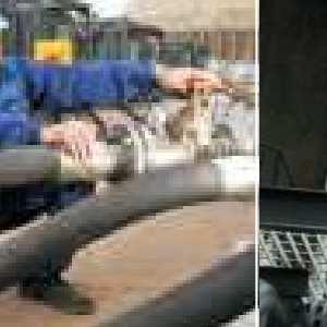
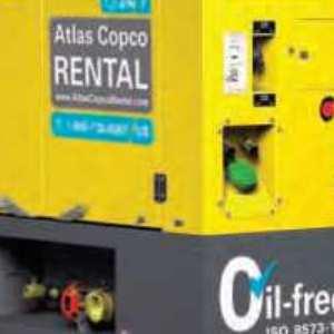
4 New NY Bridge Project Description of Underwater Noise Attenuation System (NAS) Design Unit 2 minimize to the maximum extent practicable the effects of underwater sound upon fishes in the Hudson River. 9. At least 30 days before starting installation of permanent piles within each specific in-river design unit (as identified in the March 21, 2013 letter) the Permittee must give the Department design plans and operational specifications for the underwater sound attenuation system for that design unit. Except for piles installed during the 2013 PIDP2, installation of piles may begin when the Department has given written approval of the underwater sound attenuation system for each in-river design unit. Upon Department approval the final sound attenuation plan will be posted on the project website maintained by the Permittee. 2.0 Test Piles The Pile Load Test Program uses test piles in each of the 10 design units plus the Main Span (11 total design units), with the primary purpose to confirm pile load capacities. Design Unit 2 consists of in Piers 2 to 4 and in Pier 5. Test piles were installed with an IHC S-280 impact hammer. A summary of the impact pile driving for test piles at Design Unit 2 is provided in Table 1. Table 1. Summary of Impact Pile Driving for Test Piles at Design Unit 2 Test Pile Pile Diameter Impact Hammering Date PLT-103P 9/3/2013 PLT-103 9/4/ Unconfined Multi-tier Bubble Curtain NAS Design Based on the NAS effectiveness determination in the PLT-NAS Description, the unconfined multi-tier bubble curtain was selected for further testing during test-pile installation. Refer to Attachment 2 for engineering details on the system. 3.1 NAS Components The unconfined multi-tier bubble curtain consists of aluminum bubbler rings suspended from the pile-driving template at four points, spaced a maximum of 10 feet vertically, and connected to the template using ½ - diameter wire rope. See Attachment 2 for bubbler ring dimensions and hole diameter, spacing, and orientation. The aluminum ring is connected to a dedicated compressor (Figure 1). This compressor is connected to a reservoir tank to allow a continuous supply of air throughout pile driving (Figure 1). During the installation of test piles, a flow meter and air pressure gauge are used to measure air flow and pressure (Figure 2). The air compressor is capable of supplying an air pressure of up to 100 pounds per square inch (psi) at an air flow of 1600 cubic feet per meter (cfm) to each bubbler ring (Attachment 3). The reservoir tank allows the system to supply an air flow of up to 2000 cfm, to each bubbler ring, as was demonstrated during testing. NAS Design Plans - Unit 2, Rev PLT and Underwater NAS - 2


.")
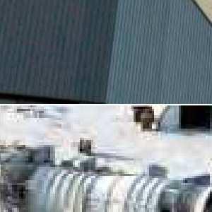
5 New NY Bridge Project Description of Underwater Noise Attenuation System (NAS) Design Unit 2 Air Compressor Reservoir Tank Figure 1. Air Compressor and Reservoir Tank Air Pressure Gauge Flow Meter Gauge Figure 2. Flow Meter and Pressure Gauge on Outlets from the Reservoir Tank to the Bubbler Ring 3.2 NAS Deployment and Operation The NAS deployment and operation proceeded as expected. After the piles were initially driven with the vibratory hammer, the bubble curtain ring was deployed with a crane and hung from the secondary template using wire rope slings and shackles (Figure 3). The air compressor/reservoir tank pumped air into the ring (Figure 4), the impact hammer was lofted, the piles were tapped (i.e., a series of minimal energy strikes), and then driven to the required depth. NAS Design Plans - Unit 2, Rev PLT and Underwater NAS - 3

6 New NY Bridge Project Description of Underwater Noise Attenuation System (NAS) Design Unit 2 Figure 3. Deployment of the Unconfined Multi-tier Bubble Curtain Figure 4. Operation of the Multi-tier Bubble Curtain 4.0 Underwater Noise Monitoring During Test Pile Installation 4.1 Methods Details of the equipment, the calibration of the equipment, the data collected, and the signal processing for underwater noise monitoring are included in the Underwater Noise Monitoring Plan. Details on the underwater noise monitoring during the installation of PLT 103P and PLT 103 are provided in the Daily Memoranda for each day of pile driving (Attachment 1). NAS Design Plans - Unit 2, Rev PLT and Underwater NAS - 4
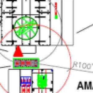
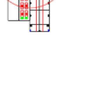
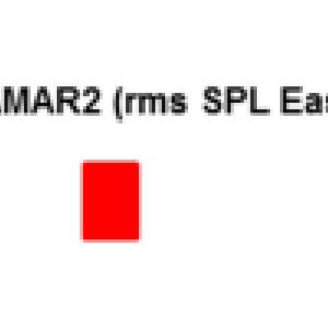
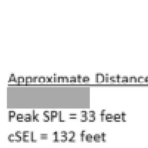
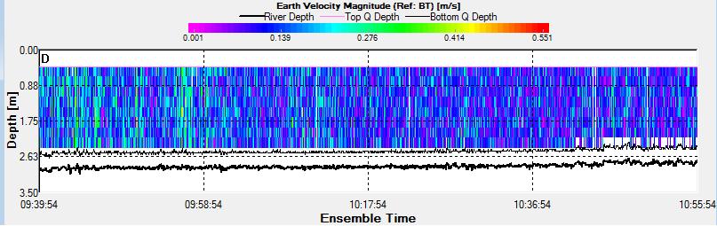
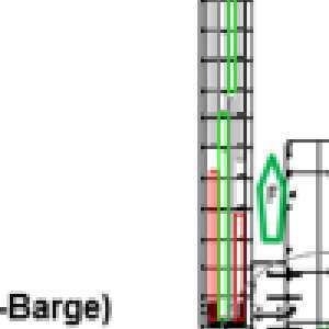
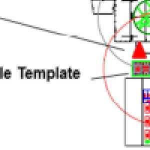
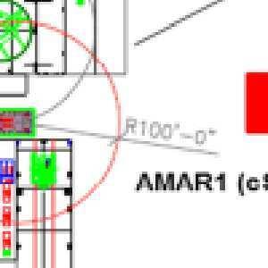
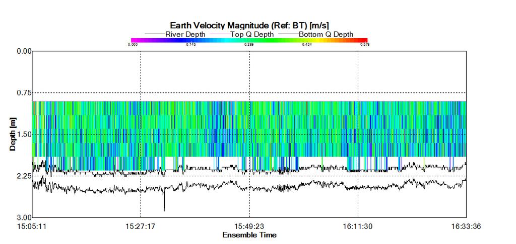
7 New NY Bridge Project Description of Underwater Noise Attenuation System (NAS) Design Unit 2 Figure 5 illustrates a typical barge and hydrophone arrangement As seen in Figure 5, a real time Autonomous Multichannel Acoustic Recorder (AMAR-RT) and two Autonomous Multichannel Acoustic Recorders (AMARs) were generally placed at the distances of the noise level thresholds predicted in the NMFS BO (although locations varied based on conditions, such as vessel traffic and tides). The AMAR-RT was continuously monitored throughout the pile driving process while data collected from the AMARs was downloaded following pile driving. The noise level thresholds predicted in the NMFS BO (April 2013) are as follows: peak SPL (sound pressure level) located on the barge or survey vessel, approximately 33 feet from the pile, based on the distance that can be safely recorded (the distance to the 206 re 1 µpa peak SPL isopleth for piles is 20 feet) csel (cumulative Sound Exposure Level) located approximately 132 feet from the pile, based on the distance from the pile to the 187 db re 1 µpa 2 -s csel isopleth for piles rms SPL (root mean square SPL) located approximately 400 feet from the pile, based on the distance from the pile to the 150 db re 1µPa rms SPL for piles Hammer Barge Figure 5. Plan View of a Typical Test Pile Barge Arrangement and Hydrophone Locations for piles Test pile installation for Design Unit 2 occurred during flood and ebb currents. Hydrophones (AMARs) were strategically placed to capture data to analyze variation in the performance of the NAS correlated with variation in the river current and barge placement. During the installation of PLT 103P the NAS was tested down-current and cross-current in a knot flood to slack current. During the installation of PLT 103 NAS was tested down-current and cross-current in a knot ebb current. Table 2 provides a summary of the underwater noise monitoring equipment deployment and position relative to the current for the driving of the two test piles. NAS Design Plans - Unit 2, Rev PLT and Underwater NAS - 5
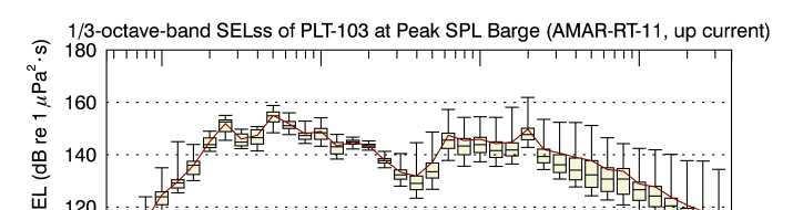
8 New NY Bridge Project Description of Underwater Noise Attenuation System (NAS) Design Unit 2 Table 2. Equipment Deployment and Position Relative to Current for PLT 103P and PLT 103 Date Test Pile No. 9/3/2013 PLT 103P Hydrophone ID Location Relative to Pile* Location Relative to Current Current During Pile Driving Distance to Pile (ft) Water depth (ft) AMAR-RT 11 Peak SPL- Barge Down-current Flood to 27 8 AMAR-221 csel East Cross-Current slack ( AMAR-228 rms SPL East Cross-current knots) /4/2013 PLT 103 AMAR-RT 11 Peak SPL-Barge Up-Current 30 8 AMAR-228 csel East Cross-Current Ebb ( knots) AMAR-221 rms SPL East Cross Current *Locations correspond to the hydrophone locations labeled in Figure 5 and are based on the following: peak SPL located on the barge or survey vessel, approximately 40 feet from the pile, based on the distance from the pile to the 206 re 1 µpa peak SPL isopleth for piles csel- located approximately 132 feet from the pile, based on the distance from the pile to the 187 db re 1 µpa 2 -s csel isopleth for piles rms SPL located approximately 400 feet from the pile, based on the distance from the pile to the 150 db re 1µPa rms SPL for piles The tests for this design unit were informed by the tests for the previous NAS tests where air flow was varied throughout pile driving but never independently of other variables, such as impact hammer energies or tidal conditions. All tests were performed at a range of tidal conditions and hammer energies which could be expected during production pile driving. Table 3 provides the number of rings deployed and the NAS settings during the installation of the two test piles. Table 3. Description of NAS During Installation of Test Piles for Design Unit 2 Date Water Depth Air Flow (cfm) Number of Rings Air Pressure (psi) Test Pile No. (ft) per Bubbler Ring 9/3/2013 PLT 103P /4/2013 PLT Results NMFS Physiological and Behavioral Thresholds In accordance with the NMFS BO Term and Condition Number 6, the monitoring program estimated (i) the peak sound pressure level (peak SPL in db re 1 µpa ) at each recorder and the distance from the pile at which the peak SPL exceeds the 206 db re 1 µpa peak, (ii) the csel at each recorder and the distance from the pile at which the csel exceeds 187 db re 1 µpa 2 s at the end of pile driving 1, and (iii) the rms SPL at each recorder and the distance from the pile at which rms SPL exceeds 150 db re 1 µpa. Table 4 provides a summary of the underwater noise levels measured at each recorder during the test pile installation. Table 5 provides the diameter of the sound level isopleths that serve as the NMFS 1 csel increases as the number of strikes increases therefore; the diameter of the 187 db isopleth also reaches a maximum at the end of piling. NAS Design Plans - Unit 2, Rev PLT and Underwater NAS - 6
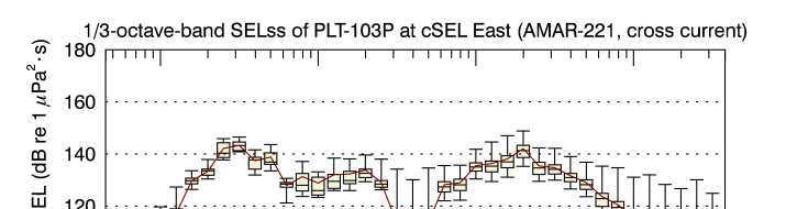
9 New NY Bridge Project Description of Underwater Noise Attenuation System (NAS) Design Unit 2 physiological and behavioral thresholds. These results show that when the NAS was operational, the diameter of the 206 db re 1 µpa peak SPL did not exceed NMFS requirement of 40 feet for piles at Design Unit 2. The largest diameter of the 206 db re 1 µpa peak SPL isopleth was 8 ft, which is less than the 206 db re 1 µpa peak SPL for the NASs tested during the 2012 PIDP. Specifically, during the 2012 PIDP the diameters of the 206 db re 1 µpa peak SPL isopleth were feet for piles (JASCO 2012) 2. Furthermore, the estimated diameter of the isopleth at the end of installation of test piles that corresponded to 187 db re 1 µpa 2 -s csel never exceeded 204 ft. The river width is approximately 15,000 ft; therefore a fish movement corridor of more than one mile [5,280 ft], which was continuous for more than 1,500 ft, was maintained throughout pile driving, in accordance with NYSDEC Permit Condition 14. Table 4. Summary of the Measured Sound Levels at Each Recorder During the PLT 103P and PLT 103 Date Max. peak SPL csel Location* Test Pile No. (db re 1 µpa) (db re 1 µpa 2- s)** Peak SPL Barge /3/2013 csel East PLT 103P rms SPL East Peak SPL Barge /4/2013 csel East PLT 103 rms SPL East *Locations correspond to the hydrophone locations labeled in Figure 5 and are based on the following: peak SPL located on the barge or survey vessel, approximately 33 feet from the pile, based on the distance from the pile to the 206 re 1 µpa peak SPL isopleth for piles csel- located approximately 132 feet from the pile, based on the distance from the pile to the 187 db re 1 µpa 2 -s csel isopleth for piles rms SPL located approximately 400 feet from the pile, based on the distance from the pile to the 150 db re 1µPa rms SPL for piles **At the completion of pile driving. Table 5. Diameters of Sound Level Isopleths that Represent NMFS Physiological and Behavioral Impact Threshold Threshold PLT 103P PLT 103 Pile Installation Duration (hh:mm)* 00:45 ~00:35** Approximate Diameter (ft) of Isopleth 206 db re 1 µpa peak SPL db re 1 µpa 2 -s csel db re 1 µpa rms SPL * Net pile driving times are rounded to the nearest minute. ** Pile Installation Duration is an approximation based on the GZA field log because the IHC read-out malfunctioned NAS Performance The NAS was tested in flood, ebb, and slack currents with hydrophones located in down-current and cross current positions (Table 2). Current speed ranged from 0 to 0.8 knots. Air flow settings ranged from air pressures of 34 to 80 psi and air flows of 900 to 2150 cfm. Although some variation in sound propagation was noted, the NMFS and NYSDEC required thresholds were not exceeded. Air pressure and air flow were psi and cfm, respectively, throughout the first phase of installation of PLT 103P and psi and cfm, respectively, during the second phase. The NAS was tested in flood to slack current with speed ranging from 0 to 0.8 knots. Hammer energy averaged 120 kip-ft throughout both phases. There was no observable effect on the measured sound levels from the 2 JASCO Underwater Acoustic Monitoring of the Tappan Zee Bridge Pile Installation Demonstration Project. NAS Design Plans - Unit 2, Rev PLT and Underwater NAS - 7
10 New NY Bridge Project Description of Underwater Noise Attenuation System (NAS) Design Unit 2 change in air pressure or the change in current. The thresholds required by the NMFS BO and NYSDEC permit were not exceeded at any point during the installation of this test pile. Air pressure and flow were psi and cfm, respectively during most of the pile installation, except a 2.5 min period from 16:03 16:05:30 when pressure fell to 34 psi when the valve from a compressor was not open. Hammer energy averaged 122 kip-ft in the first phase of pile driving and 118 kip-ft in the second phase. For PLT 103 the NAS was tested in an ebb current with speed ranging from 0.3 to 0.8 knots. The measured sound levels at the closest measurement location increased by 3 7 db during this period, but sound levels at the other two locations did not show an increase. The thresholds required by the NMFS BO and NYSDEC permit were not exceeded at any point during the installation of this test pile. PLTs 104P and 104 are piles driven at Design Unit 3, under conditions similar to the conditions at Design Unit 2. The water depth for each of these piles was 9 feet and one bubble ring was used. Air pressure and flow dropped from psi and cfm respectively during the first four minutes of PLT 104P because the valve from the air compressor to the air-tank was closed. Pile driving stopped and resumed with proper NAS operation at 11:12. Air pressure ranged between 55 and 70 psi ( cfm) for the remainder of the pile driving. Once the compressor valve was opened and with resumption of air pressure sound levels at all three recorders decreased approximately 10 db at every measurement location. For additional information regarding the PLT-104P refer to Description of Underwater Noise Attenuation System (NAS) Design Unit 3. Air pressure and flow were psi and cfm respectively. For PLT 104 hammer energy remained constant throughout pile driving but the currents dropped from 0.6 knots to slack current. However, there was no observable effect on the measured sound levels from the change in current. For additional information regarding the PLT-104 refer to Description of Underwater Noise Attenuation System (NAS) Design Unit Conclusions In accordance with NYSDEC Permit Condition 8, an underwater noise attenuation system or systems must be deployed during the driving of steel piles to minimize to the maximum extent practicable the effects of underwater sound upon fishes in the Hudson River. The PLT-NAS Description concludes that the most effective system is the one that will be capable of attenuating noise to achieve the distance thresholds required by NMFS in the BO and that can be safely deployed and retrieved repeatedly during production pile driving without affecting pile driving requirements and project schedule. Results of test pile installation indicate that the unconfined multi-tier bubble curtain with bubble rings spaced a maximum of ten feet vertically, is effective in minimizing noise in order to meet the NMFS and NYSDEC requirements. Not only did the NAS meet the requirements in full ebb and flood currents and for various NAS settings, underwater noise from pile driving isopleths were smaller than anticipated by the NMFS BO. Results indicate that the largest estimated width of the 206 db re 1µPa peak SPL isopleth was measured at 8 ft, as compared to the 40 ft anticipated by the NMFS BO. These results indicate that the size of the 206 db re 1 µpa isopleth measured for the piles in less than 10 ft of water was smaller than the 206 db re 1 µpa isopleths measured during the 2012 PIDP. Furthermore, the diameter of the 187 db re 1 µpa 2 -s csel isopleth at the end of installation of each pile was never estimated to be more than 204 ft. Therefore, the noise levels across the majority of the river at the construction site would be less than 187 db csel, and would thus provide the required corridor for sturgeon migration through the site. NAS Design Plans - Unit 2, Rev PLT and Underwater NAS - 8
11 5.0 NAS Design Plan and Operational Specifications New NY Bridge Project Description of Underwater Noise Attenuation System (NAS) Design Unit 2 The installation of the two test piles also demonstrated that the unconfined multi-tier bubble curtain is readily and safely deployable and retrievable. Given these logistical attributes, combined with the proven effectiveness at obtaining required distances to NMFS and NYSDEC thresholds, the unconfined multi-tier bubble curtain is considered most effective to minimize harm to fish in the Hudson River, to the maximum extent practicable. During production pile driving for Design Unit 2, the unconfined multi-tier bubble curtain will be deployed and retrieved in a similar manner to the PLT 103P and PLT 103 pile installations. The air pressure gauge will be used to monitor NAS operation during production pile driving. Based on dredging and armoring, the river bottom at Design Unit 2 will be approximately -11 feet at mean lower low water (MLLW). Bubbler rings and compressors will be deployed for each pile in pier 5, so that vertical spacing in the water column is a maximum of 10 feet or less at mean higher high water (MHHW). The NAS will be deployed according the Construction Work Plan. Table 6 provides the expected range of water depths at Pier 5 in Design Unit 2 and the number of bubble curtain rings to be deployed for pile driving at that pier. Table 6. Range of Water Depths at Each Design Unit 2 Pier and the Number of Bubble Curtain Rings to be Deployed Number of Bubble Pier Water Depth (feet) Curtain Rings* *The number of bubbler rings at specific piles within a pier is subject to change, based on field measurements of water depth during pile installation The NAS system contains three valves at the: 1. air compressor outlet to the reservoir tank (Figure 6), 2. reservoir tank inlet (Figure 7), 3. reservoir tank outlet (Figure 8) to the bubbler ring. Prior to impact pile driving, the compressor will be turned on and the valves will be open such that air will be supplied to the bubbler rings individually to visually confirm sufficient air to each ring. All valves will be opened during the operation of the bubble curtain. The bubble curtain will remain on during periods of active pile driving. The air pressure gauge will be used to monitor NAS operation during production pile driving. Air pressure at the outlet from the reservoir tank will be maintained at a target pressure of between 60 and 80 psi with a minimum pressure of 40 psi to each bubbler ring (Figure 9). The following will be checked for each of the piles at each pier within Design Unit 2 (as outlined in the Construction Work Plan): Reservoir tank is pressurized prior to pile driving. The tank inlet and outlet valves are open immediately prior to starting the compressor. Air pressure at each reservoir tank outlet approximately 5 minutes after pile driving begins. Visual inspection of the water surface for sufficient air bubbles. NAS Design Plans - Unit 2, Rev PLT and Underwater NAS - 9
 Design Unit 2 Figure 6.")

12 New NY Bridge Project Description of Underwater Noise Attenuation System (NAS) Design Unit 2 Figure 6. Valve at the Air Compressor Outlet to the Reservoir Tank Figure 7. Valve at the Reservoir Tank Inlet NAS Design Plans - Unit 2, Rev PLT and Underwater NAS - 10

13 New NY Bridge Project Description of Underwater Noise Attenuation System (NAS) Design Unit 2 Figure 8. Valve at the Outlet from the Reservoir Tank to the Bubble Curtain Figure 9. Air Compressor Controls NAS Design Plans - Unit 2, Rev PLT and Underwater NAS - 11
14
15
16


17
18
19
20
21
22
23
24
25
26
27
28
29


30
31

32
33
34
35
36
37
38
39
40
41
42
43
44
45
46
47
48
49

50
51


52
53
Dredging and Pile Driving Monitoring Plan Sturgeon Monitoring During Pile Driving 60-day Report 2/16/2014 4/12/2014. New NY Bridge Project
 Sturgeon During Pile Driving 60-day Report 2/16/2014 4/12/2014 for the April 18, 2014 Prepared by Tappan Zee Constructors, LLC 555 White Plains Road, Suite 400 Tarrytown, NY 10591 60-Day Sturgeon Report
Appendix F: Ecology F-6 Methodology for Estimating Potential Hydroacoustic Impacts to Abundant Hudson River Fish Species and Shortnose Sturgeon from
 Appendix F: Ecology F-6 Methodology for Estimating Potential Hydroacoustic Impacts to Abundant Hudson River Fish Species and Shortnose Sturgeon from Pile-driving Activities during Construction of the Tappan
Near-Field Sturgeon Monitoring for the New NY Bridge at Tappan Zee. Quarterly Report July 1 September 30, 2014
 Near-Field Sturgeon Monitoring for the New NY Bridge at Tappan Zee Quarterly Report July 1 September 30, 2014 Prepared by AKRF, Inc. 7250 Parkway Drive, Suite 210 Hanover, MD 21076 for New York State Thruway
Caltrans compendium of underwater sound data from pile driving 2014 update
 Caltrans compendium of underwater sound data from pile driving 2014 update Richard RODKIN 1 ; Keith POMMERENCK 2 1 Illingworth & Rodkin, Inc., United States 2 Illingworth & Rodkin, Inc., United States
Underwater Sound Level Report: I-90 Keechelus Lake Avalanche Bridge Blasting
 I-90 SNOQUALMIE PASS EAST Underwater Sound Level Report: I-90 Keechelus Lake Avalanche Bridge Blasting Prepared by: Jim Laughlin Washington State Department of Transportation Office of Air Quality and
SR 411, Lexington Bridge Underwater Noise Monitoring Results
 Northwest Region 157 Dayton Avenue North P.O. Box 3331 Seattle, WA 98133-971 Washington State Department of Transportation Douglas B. MacDonald Secretary of Transportation September 21, 26 (26) 44-4 TTY:
Final Report: Measurements of Pile Driving Noise from Control Piles and Noise-Reduced Piles at the Vashon Island Ferry Dock
 Final Report: Measurements of Pile Driving Noise from Control Piles and Noise-Reduced Piles at the Vashon Island Ferry Dock By Peter H. Dahl, Jim Laughlin, and David R. Dall Osto Executive Summary Underwater
Item 404 Driving Piling
 Item Driving Piling 1. DESCRIPTION Drive piling. 2. EQUIPMENT 2.1. Driving Equipment. Use power hammers for driving piling with specified bearing resistance. Use power hammers that comply with Table 1.
San Francisco Oakland Bay Bridge East Span Seismic Safety Project FISHERIES AND HYDROACOUSTIC MONITORING PROGRAM COMPLIANCE REPORT
 San Francisco Oakland Bay Bridge East Span Seismic Safety Project FISHERIES AND HYDROACOUSTIC MONITORING PROGRAM COMPLIANCE REPORT JUNE 2004 EA 012023 04-SF-80 KP 12.2/KP 14.3 04-ALA-80 KP 0.0/KP 2.1 Sa
UNDERWATER SOUND LEVELS ASSOCIATED WITH PILE DRIVING AT THE CAPE DISAPPOINTMENT BOAT LAUNCH FACILITY, WAVE BARRIER PROJECT
 WASHINGTON STATE PARKS CAPE DISAPPOINTMENT WAVE BARRIER PROJECT UNDERWATER SOUND LEVELS ASSOCIATED WITH PILE DRIVING AT THE CAPE DISAPPOINTMENT BOAT LAUNCH FACILITY, WAVE BARRIER PROJECT Prepared by: Jim
MEASUREMENT OF LONG-TERM AMBIENT NOISE AND TIDAL TURBINE LEVELS IN THE BAY OF FUNDY
 MEASUREMENT OF LONG-TERM AMBIENT NOISE AND TIDAL TURBINE LEVELS IN THE BAY OF FUNDY 11 th European Conference on Underwater Acoustics, 3 July 2012 Bruce Martin 1, Andrew Gerber 2, Christopher Whitt 1,
Benefit of ESTCP/SERDP Research Program on Underwater Explosive Safety
 Benefit of ESTCP/SERDP Research Program on Underwater Explosive Safety Timothy W. Shelton, PE Supervisory Research Hydraulic Engineer ERDC CHL Oct 2017 DoD has very few options for disposing UXO recovered
Naval Base Kitsap-Bangor Explosives Handling Wharf 2. Year 1 Marine Mammal Monitoring Report ( )
") Naval Base Kitsap-Bangor Explosives Handling Wharf 2 Year 1 Marine Mammal Monitoring Report (2012 2013) BANGOR, WASHINGTON April 2013 Prepared by: ACRONYMS AND ABBREVIATIONS APE American Piledriving Equipment
Naval Base Kitsap-Bangor Explosives Handling Wharf 2 Year 1 Marine Mammal Monitoring Report (2012 2013) BANGOR, WASHINGTON April 2013 Prepared by: ACRONYMS AND ABBREVIATIONS APE American Piledriving Equipment
Annex E Bridge Pier Protection Plan
 Annex E Bridge Pier Protection Plan Table E1 Bridge Types and Locations Table E2 Flow Conditions For River Sections Figure E1 Bridge Abutment Protection Figure E2 Bridge Pier Protection Figure E3 Central
WaterSense Specification for Spray Sprinkler Bodies. Version 1.0
 Version 1.0 September 21, 2017 WaterSense Specification for Spray Sprinkler Bodies 1.0 Scope and Objective This specification establishes the criteria for labeling bodies of spray sprinklers 1 under the
Final. Technical Guidance for Assessment and Mitigation of the Hydroacoustic Effects of Pile Driving on Fish
 Mitigation of the Hydroacoustic Effects of Pile Driving on Fish Prepared for: California Department of Transportation 1120 N Street Sacramento, CA 94274 Contact: Jim Andrews Prepared by: ICF Jones & Stokes
Use of a low power, airgun sound source to accurately determine sound. Transmission Loss characteristics at the proposed Robin Rigg. Windfarm site.
 Submitted to: Submitted by: The Scottish Executive On behalf of: Mr M J Swanwick Mr S J Parvin EON-UK Subacoustech Ltd Westwood Way Chase Mill Westwood Business Park Winchester Road Coventry Bishop s Waltham
1-22. KETCHIKAN, ALASKA (Thomas and Bar Point Basins) (CWIS NOS & 87071) Condition of Improvement 30 September 2007
 (CWIS NOS & 87071) Condition of Improvement 30 September 2007") KETCHIKAN HARBOR 1-22 KETCHIKAN, ALASKA (Thomas and Bar Point Basins) (CWIS NOS. 00631 & 87071) Condition of Improvement 30 September 2007 AUTHORIZATION: (1) Rivers and Harbors Act, 3 July 1930 (House
KETCHIKAN HARBOR 1-22 KETCHIKAN, ALASKA (Thomas and Bar Point Basins) (CWIS NOS. 00631 & 87071) Condition of Improvement 30 September 2007 AUTHORIZATION: (1) Rivers and Harbors Act, 3 July 1930 (House
CHAPTER 3 : AIR COMPRESSOR
 CHAPTER 3 : AIR COMPRESSOR Robotic & Automation Department FACULTY OF MANUFACTURING ENGINEERING, UTeM Learning Objectives Identify types of compressors available Calculate air capacity rating of compressor
Pile Driving and Barotrauma Effects
 Pile Driving and Barotrauma Effects AASHTO SOC Louisville, KY Jeff Lewis, Field Operations Engineer Federal Highway Administration California Division Transportation Needs Capacity Strength Constructability
Summary of Substantive Changes between the 2004 e1 and 2017 editions of ASSE 1011, Hose Connection Vacuum Breakers
 Summary of Substantive Changes between the 2004 e1 and 2017 editions of ASSE 1011, Hose Connection Vacuum Breakers Presented to the IAPMO Standards Review Committee on October 15, 2018 General: The changes
ARA PROJECT Prepared by: Peter T. Dzwilewski Applied Research Associates, Inc Shaffer Parkway Littleton, Colorado 80127
 ARA PROJECT 001974 WATER SHOCK PREDICTION FOR EXPLOSIVE REMOVAL OF OFFSHORE STRUCTURES: UNDERWATER CALCULATOR (UWC) VERSION 2.0 UPDATE BASED UPON FIELD DATA Prepared by: Peter T. Dzwilewski Applied Research
LOCAL NOTICE TO MARINERS
 USCG Notice to Mariners 3/7/18 (View full Notice here) LNM 10/18 Coast Guard District 1: U.S. Department of Homeland Security United States Coast Guard LOCAL NOTICE TO MARINERS COASTAL WATERS FROM EASTPORT,
***This summary does not include shad and herring net requirements.***
 South Carolina Department of Natural Resources Marine Resources Division Summary of Seine and Gill Net Laws (Saltwater) 2013-2014 This document should be kept on board all vessels using seines or gill
Air Operated Hydraulic Pumping Systems to 50,000 psi
 High Pressure Equipment Air Operated Hydraulic Pumping Systems to 50,000 psi PS-10: 10,000 psi PS-20: 20,000 psi PS-30: 30,000 psi PS-40: 40,000 psi PS-50: 50,000 psi PS-90: 90,000 psi High Pressure air
1805 Series Relief Valves
 October 2011 1805 Series Relief Valves P1026 1805G Type 1805-2 Type 1805-4 Figure 1. Typical 1805 Relief Valves Introduction The 1805 Series relief valves are designed for use in farm tap applications
Measurements of underwater noise in the Arun River during piling at County Wharf, Littlehampton
 Submitted to: Submitted by: Mr Chris Moore Dr J Nedwell David Wilson Homes Ltd Subacoustech Ltd 15 Horsham Court Long Barn City Business Centre Mandalay Farm Brighton Road Forester Road Horsham Soberton
EFFECTS ON CUTTER SUCTION DREDGE PRODUCTION WHILE DREDGING SIMULATED DEBRIS IN THE LABORATORY
 EFFECTS ON CUTTER SUCTION DREDGE PRODUCTION WHILE DREDGING SIMULATED DEBRIS IN THE LABORATORY R. Randall 1, M. Warwick 2, J. Henriksen 3, D. Young 4, and A. Manikantan 5 ABSTRACT The cutter suction dredge
TOP:001.3 U.S. Fish and Wildlife Service TECHNICAL OPERATING PROCEDURE
 TOP:001.3 March 12, 2015 U.S. Fish and Wildlife Service Marquette Biological Station 3090 Wright Street Marquette, Michigan 49855 U.S.A. and U.S. Fish and Wildlife Service Ludington Biological Station
Exhibit 4. Determination of Static Pressure Performance of the Healy Clean Air Separator (Executive Orders VR-201-N and VR-202-N)
") 1 APPLICABILITY Exhibit 4 Determination of Static Pressure Performance of the Healy Clean Air Separator (Executive Orders VR-201-N and VR-202-N) Definitions common to all certification and test procedures
1 APPLICABILITY Exhibit 4 Determination of Static Pressure Performance of the Healy Clean Air Separator (Executive Orders VR-201-N and VR-202-N) Definitions common to all certification and test procedures
SEISMIC SURVEY GREENLAND 2014 Underwater sound propagation for North East Greenland offshore seismic survey
 TGS February 2014 SEISMIC SURVEY GREENLAND 2014 Underwater sound propagation for North East Greenland offshore seismic survey Appendix: NEG14 modelling results Mark Mikaelsen PROJECT Seismic Survey Greenland
Cover Page for Lab Report Group Portion. Pump Performance
 Cover Page for Lab Report Group Portion Pump Performance Prepared by Professor J. M. Cimbala, Penn State University Latest revision: 02 March 2012 Name 1: Name 2: Name 3: [Name 4: ] Date: Section number:
The Cyclone Tire Deflation & Inflation Tool
 The Cyclone Tire Deflation & Inflation Tool How it works; This tool operates on compressed air that activates our patent pending venturi that creates a ultra-high vacuum, that draws the air from inside
STRUCTURE S-65 PURPOSE SPILLWAY OPERATION
 STRUCTURE S-65 This structure is a reinforced concrete, gated spillway with discharge controlled by three cable operated, vertical lift gates, and a reinforced concrete lock structure with two pairs of
EPA R6 Dive Team Operations Report. San Jacinto Waste Pits Channelview, TX December 9-10, 2015
 EPA R6 Dive Team Operations Report San Jacinto Waste Pits Channelview, TX December 9-10, 2015 BACKGROUND The San Jacinto River Waste Pit Site history has been documented in several documents prepared for,
Outlet Structures T-12
 Description This section provides guidance and details for outlet structures for use primarily with BMPs utilizing sedimentation, (i.e., extended detention basins (EDBs), retention ponds, and constructed
SECTION PRESSURE TESTING OF PIPING
 SECTION 15044 PRESSURE TESTING OF PIPING PART 1 - GENERAL 1.01 DESCRIPTION A. Scope of Work: This section specifies the leakage and pressure testing of piping. B. Testing Records: PART 2 - PRODUCTS 2.01
Pump Performance Testing
 Pump Performance Testing SAFETY Keep water away from all electrical equipment except the pump, and do your best to keep the pump motor dry. Don t handle the power supply or multimeter(s) with wet hands
RVSS Appendix A Overview
 RVSS Appendix A Overview Presented at RVTEC 2008 by Rich Findley rfindley@rsmas.miami.edu Definitions WINCH OWNER: The party or their representative who is normally responsible for the operation, inspection,
Ketchikan Harbors Thomas Basin and Bar Point Harbor
 Ketchikan Harbors Thomas Basin and Bar Point Harbor Condition of Improvements 30 December 2014 Thomas Basin & Bar Point Harbors Ketchikan, Alaska (CWIS No. 000631 & 087071) Authorization (1) Rivers and
Nome Harbor Page 2 of 12
 Nome Harbor Nome Harbor Page 2 of 12 Condition of Improvements 30 December 2015 Nome Harbor, Alaska (CWIS No. 010422, 012270, 072742, 087755) Authorization (1) Rivers and Harbors Act, 8 August 1917 (House
Effect on Marine Life by Noise of Offshore Wind Farm S.JIANG 1 & J.P. HOU 1
 5th International Conference on Advanced Design and Manufacturing Engineering (ICADME 2015) Effect on Marine Life by Noise of Offshore Wind Farm S.JIANG 1 & J.P. HOU 1 1 Third Institute of Oceangraphy,SOA,Xiamen,Fujian,China
Janek LAANEARU and Aleksander KLAUSON Department of Mechanics, Tallinn University of Technology
 seminar in Tallinn, 5.01.013 PRINCIPAL UNDERWATER NOISE SOURCES IN BALTIC SEA AND METRICS USED IN NOISE LEVEL ASSESSMENT Janek LAANEARU and Aleksander KLAUSON Department of Mechanics, Tallinn University
Minimal influence of wind and tidal height on underwater noise in Haro Strait
 Minimal influence of wind and tidal height on underwater noise in Haro Strait Introduction Scott Veirs, Beam Reach Val Veirs, Colorado College December 2, 2007 Assessing the effect of wind and currents
Perched Box Caisson Overview. January 2014
 Perched Box Caisson Overview January 2014 Why perched box caissons? Perched box caissons are used to construct the portion of the river piers that will support the steel arch spans Construction can occur
TECHNICAL DATA. Q = C v P S
 Page 1 of 13 1. DESCRIPTION The Viking 6 Model G-6000 Dry Valve Riser Assembly consists of a small profile, light weight, pilot operated valve that is used to separate the water supply from the dry sprinkler
8.4 Effects of Using Concrete Cooling System Entrainment Impingement Thermal Discharge
 TABLE OF CONTENTS 1.0 INTRODUCTION... 6 2.0 BACKGROUND AND CONSULTATION HISTORY... 6 3.0 DESCRIPTION OF THE PROPOSED ACTION... 8 3.1 Federal Actions... 8 3.2 Summary of Proposed Action... 9 3.3 Required
Practical Guide. By Steven T. Taylor, P.E., Member ASHRAE
 ractical Guide The following article was published in ASHRAE Journal, March 2003. Copyright 2003 American Society of Heating, Refrigerating and Air- Conditioning Engineers, Inc. It is presented for educational
Characterizing The Surf Zone With Ambient Noise Measurements
 Characterizing The Surf Zone With Ambient Noise Measurements LONG-TERM GOAL Grant Deane Marine Physical Laboratory Scripps Institution of Oceanography La Jolla, CA 93093-0213 phone: (619) 534-0536 fax:
TECHNICAL DATA. Q = C v P S
 January 6, 2012 Preaction 348a 1. Description Viking supervised Surefire Preaction Systems utilize the Viking G-6000P Valve. The small profile, lightweight, pilot operated Viking G-6000P Valve comes complete
TECHNICAL DATA. Q = C v P S
 January 6, 2012 Preaction 333a 1. Description Viking supervised Surefire Preaction Systems Utilize the Viking G-3000P Valve. The small profile, lightweight, pilot-operated Viking G-3000P Valve comes complete
Becker* Products Below Ground Ball Valve Regulators
 GE Oil & Gas Becker* Products Below Ground Ball Valve Regulators Reduce Noise Levels at Large Volume Regulator Stations GE s Becker* Below Ground ball valve regulator has the long-term proven reliability,
TECHNICAL DATA. Q= Cv S
 Page 1 of 13 1. DESCRIPTION The Viking 4 inch Model G-4000 Dry Valve Riser Assembly consists of a small profile, light weight, pilot operated valve that is used to separate the water supply from the dry
North American sealing solutions Bridge Plug Ball Drop Frac Plug Caged Ball Frac Plug
 North American sealing solutions Bridge Plug Ball Drop Frac Plug Caged Ball Frac Plug The North American Sealing Solutions composite bridge plug, caged ball and ball drop (flow thru) frac plug provide
The Discussion of this exercise covers the following points:
 Exercise 3-2 Orifice Plates EXERCISE OBJECTIVE In this exercise, you will study how differential pressure flowmeters operate. You will describe the relationship between the flow rate and the pressure drop
Design of a Solid Wall Transonic Wind Tunnel
 Design of a Solid Wall Transonic Wind Tunnel David Wall * Auburn University, Auburn, Alabama, 36849 A solid wall transonic wind tunnel was designed with optical access from three sides to allow for flow
TEST BENCH SAFETY VALVES ¼ - 5 DN10 DN125
 TEST BENCH SAFETY VALVES ¼ - 5 DN10 DN125 Model: VC-40-VYC Table of contents 1. - Installing the test bench 1.1.1- Connecting the compressed air / nitrogen source 1.1.2- Maximum test pressure according
M-06 Nitrogen Generator (Nitrogen Making Machine)
") Guideline No.M-06 (201510) M-06 Nitrogen Generator (Nitrogen Making Machine) Issued date: 20 th October, 2015 China Classification Society Foreword This Guideline is a part of CCS Rules, which contains
Guideline No.M-06 (201510) M-06 Nitrogen Generator (Nitrogen Making Machine) Issued date: 20 th October, 2015 China Classification Society Foreword This Guideline is a part of CCS Rules, which contains
Reliance Industries, LLC. Installation, Operation, Inspection and Maintenance Instructions for the Skyline Horizontal Lifeline System
 Reliance Industries, LLC Installation, Operation, Inspection and Maintenance Instructions for the Skyline Horizontal Lifeline System 6310 Portable Lifeline System using 3/8 7x19 Steel Wire Rope with the
Air Eliminators and Combination Air Eliminators Strainers
 Description Air Eliminators and Combination Air Eliminator Strainers are designed to provide separation, elimination and prevention of air in piping systems for a variety of installations and conditions.
REVISED SILT CURTAIN DEPLOYMENT PLAN
 Contract No.: HY/2009/11 Central Wanchai Bypass, North Point Reclamation REVISED SILT CURTAIN DEPLOYMENT PLAN Name Prepared by: China Harbour Engineering Co., Ltd. China Road and Bridge Corporation Joint
Swimming Pool Requirements
 Swimming Pool Requirements 8040 S. 6th Street Oak Creek, WI 53154 (414) 766-7000 www.oakcreekwi.org Revised: August 8. 2017 PERMITS A permit from the Inspection Department is required prior to putting
EMERGENCY WALL MOUNTED HAND OPERATED DELUGE SHOWER
 EMERGENCY WALL MOUNTED HAND OPERATED DELUGE SHOWER Installation, Operating & Maintenance Instructions EW1050 I00232_Mar 2016 NOTE: THIS DOCUMENT IS TO BE LEFT ONSITE WITH FACILITY MANAGER AFTER INSTALLATION
Assessment of cumulative Sound Exposure Levels (SEL) for marine piling events
 for marine piling events") Assessment of cumulative Sound Exposure Levels (SEL) for marine piling events P A Lepper 1, S P Robinson 2, M A Ainslie 3, P D Theobald 2, C A F de Jong 4 1 Loughborough University, Leicestershire, U K,
Assessment of cumulative Sound Exposure Levels (SEL) for marine piling events P A Lepper 1, S P Robinson 2, M A Ainslie 3, P D Theobald 2, C A F de Jong 4 1 Loughborough University, Leicestershire, U K,
DIRECT AND INVERTED PENDULUMS. Model DP & RP. Roctest Limited, All rights reserved.
 INSTRUCTION MANUAL DIRECT AND INVERTED PENDULUMS Model DP & RP Roctest Limited, 2006. All rights reserved. This product should be installed and operated only by qualified personnel. Its misuse is potentially
Reliance Industries, LLC Operating instructions for the / Bolt-on D-Ring Anchorage. Model # 3071
 Reliance Industries, LLC Operating instructions for the 3071-1 / 3071-2 Bolt-on D-Ring Anchorage Model # 3071 Reliance Industries, LLC PO Box 140008 Denver, CO 80214 Ph. (800) 488-5751 Ph. (303) 424-8650
Valve Inspection & Testing
 Inspection & Testing in accordance with API 598 Valve Inspection & Testing Shell Test (Body Hydro Test): - Each valve shall be tested in accordance with ASME B 16.34 for ASME valves. Shell test pressure
TEST BENCH FOR SAFETY VALVES
 TEST BENCH FOR SAFETY VALVES 1) Hydro panel : This Panel possesses This Bench Contains One Panel and One Reservoir. 1 No. Monobloc Version : Single Phase AC, 50 Hz Type of Duty :S1 (Continuous) Class of
River Bridge - Test Shaft-1 Clarke County, MS, 4/2/2012
 Page 1 of 9 The enclosed report contains the data and analysis summary for the SoniCaliper shaft caliper, performed at River Bridge (Test Shaft-1), Clarke County, MS on Monday, April 02, 2012 by Dave Jakstis.
Type , , S2.20 Specialized test procedure Procedure for testing LPG bulk meters using a vapour displacement prover
 Field Inspection Manual Part: 4-STP Section: 26 Page: 1 of 14 Type 52.11-13, 52.21-23, S2.20 Specialized test procedure Procedure for testing LPG bulk meters Application This test is applied to LPG bulk
Gas Gathering System Modeling The Pipeline Pressure Loss Match
 PETROLEUM SOCIETY CANADIAN INSTITUTE OF MINING, METALLURGY & PETROLEUM PAPER 2005-230 Gas Gathering System Modeling The Pipeline Pressure Loss Match R.G. MCNEIL, P.ENG. Fekete Associates Inc. D.R. LILLICO,
INSTALLATION, OPERATION AND SERVICE MANUAL ABS AIR BAG LIFT
 INSTALLATION, OPERATION AND SERVICE MANUAL ABS AIR BAG LIFT P.O. Box 1058 1058 West Industrial Avenue Guthrie, OK 73044-1058 405-282-5200 FAX: 405-282-8105 www.autoquip.com Item # 830ABS Version 1.0 07/2001
THE INNER WORKINGS OF A SIPHON Jacques Chaurette p. eng. January 2003
 THE INNER WORKINGS OF A SIPHON Jacques Chaurette p. eng. www.lightmypump.com January 2003 Synopsis The objective of this article is to explain how a siphon works. The difference between low pressure, atmospheric
Impact of Dredging the Lower Narrow River on Circulation and Flushing
 Impact of Dredging the Lower Narrow River on Circulation and Flushing Craig Swanson Ph.D. Swanson Environmental Alex Shaw Ocean Engineering, URI Prof. Malcolm L. Spaulding Ocean Engineering, URI 29 January
FIU Digital Commons. Florida International University. Henry O. Briceño Florida International University,
 Florida International University FIU Digital Commons SERC Research Reports Southeast Environmental Research Center 2015 Water Quality Monitoring Project for Demonstration of Canal Remediation Methods Florida
A REVIEW OF THE 2000 REVISIONS TO ANSI 2530/API MPMS 14.3/AGA REPORT NO. 3 - PART2 Paul J. LaNasa CPL & Associates
 A REVIEW OF THE 2000 REVISIONS TO ANSI 2530/API MPMS 143/AGA REPORT NO 3 - PART2 Paul J LaNasa CPL & Associates PO Box 801304, Houston, TX 77280-1304 ABSTRACT Periodically, natural gas measurement standards
Modeling Results for Glacier Bay
 Chapter 9 Modeling Results for Glacier Bay Finally, attention is now turned to a number of specific results of interest for the Glacier Bay domain. 9.1 Water Surface Elevation In the previous chapter,
TECHNICAL DATA Q = C. v P S. 2 Model G-2000 Dry valve. Page 1 of 13
 Page 1 of 13 1. Description The Viking 2 Model G-2000 Dry Valve Riser Assembly consists of a small profile, light weight, pilot operated valve that is used to separate the water supply from the dry sprinkler
Fundamentals of Compressed Air Systems. Pre-Workshop Assignment
 Page 1 In order to ensure that the Compressed Air Challenge Fundamentals of Compressed Air Systems Training is most useful to you, it will be important for you to bring information about your plant s compressed
PRO SINK -R 1 and 2. Dilution system CONTENTS
 PRO SINK -R 1 and 2 Dilution system CONTENTS 1.0 Product description 2 2.0 Warnings.. 3 3.0 Installation procedure 4 4.0 Plumbing connections 4 5.0 Technical features.. 5 6.0 Maintenance... 6 7.0 Troubleshooting......6
Water Hammer In Irrigation Systems 1
 CIR828 1 G. A. Clark and D. Z. Haman 2 Irrigation system design includes pump sizing and selection, valve sizing and selection, and pipe sizing as well as the proper selection and placement of many other
APPENDIX P. Noise Model Results and Supporting Material
 APPENDIX P Noise Model Results and Supporting Material Table of Contents Appendix P1 Summary of Technical Approach Appendix P2 Model Summary and Output Data Appendix P3 Illingworth & Rodkin Survey Report
PETERSEN 161-SERIES HIGH PRESSURE LIFTING AIR BAGS OPERATING INSTRUCTIONS WARNING!
 PETERSEN 161-SERIES HIGH PRESSURE LIFTING AIR BAGS OPERATING INSTRUCTIONS WARNING! Read and understand instructions before using Petersen Plugs. Failure to comply may result in property damage, serious
VRS Assembly & Operating Instructions
 VRS Assembly & Operating Instructions Models VRS-18 Pn #270003 VRS-24 Pn #270006 VRS-30 Pn #270010 Not for use on pressure vessels equipped with Automatic exhaust valve (680 controls) EMPIRE ABRASIVE EQUIPMENT
TECHNICAL MANUAL CALIBRATION PROCEDURE FOR PRESSURE GAUGE. This publication replaces T.O. 33K dated 30 January 2012.
 TECHNICAL MANUAL CALIBRATION PROCEDURE FOR GAUGE This publication replaces T.O. 33K6-4-427-1 dated 30 January 2012. Distribution Statement C - Distribution authorized to U. S. Government agencies and their
WATER MADE EASY MARINE ENERGY MUNICIPAL INDUSTRIAL
 Capital Controls Series 71V3000 The Series 71V3000 electrically-heated vaporizer automatically vaporizes and superheats liquid chlorine, sulfur dioxide or ammonia at a rate controlled by the gas feed system.
TECHNICAL DATA. Q = C v P S
 Preaction 346a 1. Description The 6 Model G-6000P Electric Release Preaction System Riser Assembly can be used as a Single Interlock Preaction System with Electric Release, or as a Double Interlock Preaction
Geo-Vibro Corer
 High Frequency Vibro Coring System Operational Features Proven performance & high quality cores 30 kn impulse at 30 Hz for fast penetration Reliable, lightweight & cost effective Modular construction (cores
Blue River Technologies Port-A-Poly Mixer w/2.5 GPH LMI Pump And Secondary Water Dilution Line INSTALLATION AND OPERATION
 Blue River Technologies Port-A-Poly Mixer w/2.5 GPH LMI Pump And Secondary Water Dilution Line INSTALLATION AND OPERATION Install your Blue River Technologies Port-A-Poly mixing system in a clean dry area.
Request Number IR1-12: Flow Passage. Information Request
 Request Number IR1-12: Flow Passage Information Request Provide additional information about the 100 metre flow passage channel scenario between the Westshore Terminals and the proposed Project terminal
WASHINGTON CONSERVATION DISTRICT STANDARD OPERATING PROCEDURE (S.O.P.)
") Page 1 of 18 Water Monitoring Program WASHINGTON CONSERVATION DISTRICT STANDARD OPERATING PROCEDURE (S.O.P.) No. 1 FLOW MONITORING Page 2 of 18 Water Monitoring Program Standard Operating Procedure No.
Page 1 of 18 Water Monitoring Program WASHINGTON CONSERVATION DISTRICT STANDARD OPERATING PROCEDURE (S.O.P.) No. 1 FLOW MONITORING Page 2 of 18 Water Monitoring Program Standard Operating Procedure No.
PRINCIPAL UNDERWATER NOISE SOURCES IN BALTIC SEA AND METRICS USED IN NOISE LEVEL ASSESSMENT
 Tallinn meeting 25.01.2013 PRINCIPAL UNDERWATER NOISE SOURCES IN BALTIC SEA AND METRICS USED IN NOISE LEVEL ASSESSMENT Janek LAANEARU and Aleksander KLAUSON Department of Mechanics, Tallinn University
TECHNICAL DATA. Q = C v P S
 January 6, 2012 Preaction 347a 1. Description Viking supervised Double-Interlocked Electric/Pneumatic Release Preaction Systems utilize the Viking G-6000P Valve. The small profile, lightweight, pilot operated
VETROSON. OXY-GEN SYSTEMS (Oxygen Generating Systems) Question & Answer Brochure
 Question & Answer Brochure") VETROSON OXY-GEN SYSTEMS (Oxygen Generating Systems) Question & Answer Brochure Q & A VETROSON OXY-GEN SYSTEMS 1) Q. How does the VETROSON OXY-GEN System work? A: A simplified explanation is that air (21%
VETROSON OXY-GEN SYSTEMS (Oxygen Generating Systems) Question & Answer Brochure Q & A VETROSON OXY-GEN SYSTEMS 1) Q. How does the VETROSON OXY-GEN System work? A: A simplified explanation is that air (21%
Reliance Industries, LLC. Installation, Operation, Inspection and Maintenance Instructions for the Skyline Horizontal Lifeline System
 Reliance Industries, LLC Installation, Operation, Inspection and Maintenance Instructions for the Skyline Horizontal Lifeline System 6300 Permanent Lifeline System using 3/8 7x19 Steel Wire Rope with the
Bridge Plugs, Ball Drop & Caged Ball Plugs For Zone Isolation
 Bridge Plugs, Ball Drop & Caged Ball Plugs For Zone Isolation ADVANTAGE composite bridge plug, caged ball and ball drop (flow thru) frac plug provide a means to isolate multiple zones during high pressure
Chapter 8 Manual Depth Measurement Techniques
 Chapter 8 Manual Depth Measurement Techniques 8-1. General Scope and Applications Manual depth measurement techniques are used for many under water engineering and construction applications. These methods
then the work done is, if the force and the displacement are in opposite directions, then the work done is.
 1. What is the formula for work? W= x 2. What are the 8 forms of energy? 3. Write the formula for the following: Kinetic Energy Potential Energy 4. If the force and the displacement are in the same direction,
1.3 LIMITATIONS: The following application limitations must be recognized and considered before using this product:
 3965 Pepin Avenue Red Wing, MN 55066-1837 Toll Free: (800) 328-6146 Phone: (651) 388-8282 Fax: (651) 388-5065 www.protecta.com User Instruction Manual AJ720A Concrete Anchor This manual is intended to
Installation, commissioning and servicing instructions
 3838.10 www.caleffi.com Inclined pressure reducing s opyright 2018 aleffi 33 series Installation, commissioning and servicing instructions Function Pressure reducing s are installed in residential water