KISS REBREATHERS CLASSIC KISS MANUAL. MSL Jetsam/Classic KISS manual R.7
|
|
|
- Herbert Crawford
- 6 years ago
- Views:
Transcription


1 KISS REBREATHERS CLASSIC KISS MANUAL MSL Jetsam/Classic KISS manual R.7
2 READ THE MANUAL!!!! IN ORDER TO FULLY UNDERSTAND YOUR NEW REBREATHER, THE COMPO NENTS, HOW THEY WORK, HOW TO HANDLE AND TREAT THEM, YOU MUST READ THE MANUAL IN FULL, FOR YOUR REBREATHER. SPORT KISS OWNERS SHOULD READ THE SPORT KISS MANUAL. CLASSIC KISS OWNERS SHOULD READ THE CLASSIC KISS MANUAL. EXPLORER OWNERS SHOULD READ BOTH THE EXPLORER AND CLASSIC MANUALS. CLASSIC OWNERS WHO HAVE UPGRADED TO SOME OF THE EXPLORER COMPONENTS SHOULD READ BOTH THE CLASSIC AND EXPLORER MANUALS. THIS SHOULD BE DONE PRIOR TO DIVING OR SERVICING THIS UNIT!!! SPECIAL ATTENTION SHOULD BE PAID TO ALL NOTES &/OR WARNINGS; THEY MUST BE READ AND UNDERSTOOD!!!! FAILURE TO DO SO, MAY CAUSE SERIOUS INJURY OR DEATH!!!! YOU MUST BE A LEGAL ADULT IN THE AREA IN WHICH YOU LIVE IN ORDER TO PURCHASE AND DIVE A KISS REBREATHER. As with all scuba diving equipment, your KISS rebreather components should be serviced annually by a trained technician. For those diving frequently, servicing may be required more o en. ALL INFORMATION IN THIS MANUAL IS SUBJECT TO CHANGE. Please visit our website, for updated manuals. 2 MSL Jetsam/Classic KISS manual R.7


3 THIS IS NOT A JOKE!! Par cipa on in rebreather diving can result in serious injury or death to you, the diver! The warning on the Classic KISS rebreather is not a joke. Before beginning your dive, you must consider the risks involved. The Classic KISS consists of many parts. All of these components will eventually fail. Careful maintenance, assembly, and tes ng will not prevent this from happening. At best, it will delay the failure. The Classic KISS is not automa c in any way. It requires constant monitoring, a complete awareness of the poten al problems likely to be encountered, and full knowledge of how to deal with whatever problems may occur. If you do not have adequate training, equipment, physical condi oning, and a proper mind set, do not get in the water. The diver, YOU, has the final responsibility for his or her own safety and ac ons while using this rebreather. All components of the Classic KISS must be in good working order and be properly assembled and tested to reduce the risk of failure. Regardless of the training and experience of the diver and the reliability of the rebreather the risk of serious injury and/ or death can never be reduced to zero. This manual is not a complete text on the maintenance and opera on of the Classic KISS. The diver must complete a proper training course covering the maintenance, tes ng and opera on of the rebreather before diving this equipment. The rebreather can malfunc on while diving even when properly assembled and having passed all pre dive tests. Only carrying adequate bailout gas and having the training and skills necessary to u lize the bailout system can reduce, but never eliminate, the risk of equipment failure. 3 MSL Jetsam/Classic KISS manual R.7
4 TABLE OF CONTENTS Informa on Page 6 Specifica ons Page 10 Parts List Page 11 Schema c Page 12 Components Page 13 Classic KISS BASIC Informa on & Instruc ons page 14 Unpacking & Disassembly Page 17 O Ring Installa on Page 19 Assembly Page 21 Ballast & Mouthpiece posi oning Page 21 Counterlungs Page 22 Counterlung size Page 23 Manifold Page 24 Automa c Diluent Valve (ADV) Page 24 Quick Disconnects Page 25 Tank & BCD Installa on Page 27 Changing the Scrubber Page 28 Posi ve/nega ve Tes ng Page 30 Sensor Installa on Page 33 Jetsam Triple Display, Info & Calibra on Page 35 Replacing Ba eries, Meters, Circuit Boards Page 38 Replacing a Single Display Case Page 40 Replacing the Wire Page 42 Display Troubleshoo ng Page 43 Sensor Informa on Page 44 Care for Fischer Connectors & Cables Page 45 Shearwater HUD Page 46 Manual Add Valve/Metering Orifice Page 49 Adjus ng the Oxygen Flow Rate Page 51 Manual Add Valve Trouble Shoo ng Page 53 Exhaust Valve/ADV/Work of Breathing Page 56 Mouthpiece Disassembly (DR or Apeks second stage) Page 60 Mouthpiece Parts List (DR or Apeks second stage) Page 62 Mouthpiece Reassembly (DR or Apeks second stage) Page 63 Mouthpiece Tes ng (DR or Apeks second stage) Page 64 Mouthpiece Servicing & Troubleshoo ng Page 65 4 MSL Jetsam/Classic KISS manual R.7


5 Pre dive Checklist s Page 67 Training & Basic Skills Page 70 KISS Minimum Training Standards Page 71 Scrubber Dura on Page 74 Warranty Page 75 O Ring List Page 76 Classic EXPLORER manual Page 78 HOLLIS mouthpiece manual Page 103 The photographs in this manual were taken by Curt Bowen, Alan Studley, Doug Ebersole, and Kim Mikusch. 5 MSL Jetsam/Classic KISS manual R.7
6 INFORMATION Welcome to the Classic KISS users manual. This manual covers a variety of informa on. It will assist you in preparing a new unit with instruc ons on O ring inser on and general assembly. It will also provide you with informa on on adjus ng and servicing your rebreather. It is important that this manual be read if full prior to diving the unit. Purchasing a rebreather is a big decision for most divers. KISS Rebreathers would like to help you make the best decision possible. We want you to choose a unit which suits your diving, your budget, and where you get the features that you desire in a rebreather. You will, no doubt, be diving this rebreather for many years and we would like you to think about your decision carefully. When analyzing the data try to think beyond your upcoming training course and the next few dives. Try and think about the long term benefits or problems you may experience. There are many ques ons that you should ask prior to making a decision. The answers to these ques ons will help you understand how the rebreather works, and help you focus on what features are important to you. If you don t get an answer from your dealer or instructor, I would suggest going directly to the manufacturer. I have listed many ques ons below with my answers. Any ques ons or concerns about my ques ons and comments are welcome. Please feel free to or call. Mike Young, Owner 30 QUESTIONS. 1. Does the manufacturer provide clear and detailed informa on on what the unit comes with, what it does not come with, and what the cost is? The KISS brochures and price sheets outline what is included and what isn t. But recently I have redesigned them so that the informa on is even clearer. In talking with divers, I have found that many people have been frustrated with hidden costs on other units. We at Jetsam don t want to fall into that category and I have made an effort to be very clear!! 2. Does the manufacturer have a proven track record on excellent customer service and will they listen to your comments and concerns? Will they answer your ques ons honestly and will they be straight forward? The KISS rebreathers have been selling since 1998 with the first units designed in Jetsam Technologies Ltd. has proven to have excellent customer service, and we always love to hear from KISS divers. Any comments and concerns are looked at and responded to immediately. I know that every unit has features that divers like, and some that they don t prefer. Any ques ons that you ask us about the features on the KISS rebreathers will be answered truthfully and we can go over the pro s and con s of all the features together. (Every rebreather on the market will have pro s & cons) 3. How many components make up the rebreather? How much is there to go wrong or break? If something does break, is it easily repairable and can it be done at a reasonable cost? The KISS rebreathers are easily the most straight forward and simple units on the market. We work with the philosophy that anything and everything will eventually break. And when you take a piece of equipment into water, especially salt water, that could happen sooner rather than later. Due to this, we have built the KISS rebreathers to have the least amount of components possible and to make the components that we use durable and easily repairable if required. You can choose to do all repairs yourself, have your local KISS dealer do them for you, or send your components back to us. 4. Do you need to send any components back to the manufacturer for regular servicing? All parts of the KISS units can be serviced by either the diver or by an authorized dealer. Should you choose to, parts can be returned to Jetsam for servicing. 5. Can I modify the unit, should I choose to do so? Over the years, KISS divers have made various modifica ons to their units. The posi on of Jetsam Technologies Ltd. is that modifica ons to the KISS rebreathers are extremely dangerous and are strictly prohibited. Any user making their own modifica ons are viola ng the terms of the End User Acknowledgment and Waiver and does so at their own risk. It has come to our a en on that some modifica ons are deemed unsafe and dangerous. As a result we have had to change our policy to only allow approved modifica ons. 6 MSL Jetsam/Classic KISS manual R.7
7 6. How far from home are you comfortable taking your rebreather and s ll feel confident that you will be able to dive? Is your spare parts kit and tool kit small and easy to carry and transport? The KISS rebreathers are known to be the most reliable rebreathers on the market. KISS divers rarely miss a dive. The units are so robust that it isn t o en that something goes wrong. Also, spare parts are well priced, easy to install onto the units and most of them fit into a small zip lock bag! 7. What happens if you damage your display? Are backups reasonably priced and easy to carry? Is it a reasonable cost to repair the damaged display? Unlike fully electronic units, the KISS rebreathers have affordable displays. All of our display op ons are reasonably priced and easy to install. You can choose to purchase any of our displays as spares. They are small and light which makes them easy to pack for a trip. The Jetsam display is user repairable, or it can be sent back to us for a quick repair at a reasonable cost. 8. Does the rebreather you are looking at purchasing offer you a variety of displays or the op on of buying it with no display? Are they giving you choices? The KISS rebreathers are available with many display op ons. You can decide for yourself which features are important to you. Or, you can opt to buy your KISS rebreather without a display system. With any display system that you choose, remember that there are pros and cons. Ques ons to ask include, what is the cost, how easy is it to change or charge the ba ery, how durable is the case, and probably most importantly, how easy is it to calibrate the display. If you buy a display system that is not approved by Jetsam, you must be certain that it works appropriately! 9. Is the unit capable of keeping a good posi ve and nega ve seal? Or is it always a struggle to keep the unit water ght? With the KISS rebreathers, you know that you should have both a good posi ve and nega ve test. If you don t, there is a leak. If you aren t sure if the test is good, then you probably have a small leak. Tes ng is easy to do, as both the lungs and loop hoses are accessible and are the key components which need to be watched while tes ng. If one of the tests fails, it isn t difficult to find the leak as the units have a simple design. 10. Are the manual addi on gas valves easy to access, and can you choose where to run the hoses and valve so that it suits you? The gas addi on valves on the KISS rebreathers are designed so that they sit over your shoulder. The valve can be accessed with either hand. Also, it can be secured to any part of your front area. Addi onally the hoses can be swapped around so that the valve comes around your side, by your waist and secured in that area. Again, this way the valve can be accessed by either hand. KISS divers can determine what suits them best and dive accordingly. 11. How easy is it to assemble and test the unit? Is it complicated or simple? The KISS rebreathers are well known for their simplicity and ease of assembly. Whether you are preparing for a dive, or cleaning your unit, you will find that your pre dive checks, or changing your absorbent and washing your loop will take only minutes. 12. How many points of entry to the loop are there? Are there many fi ngs and tubing? Are they well sealed? If something goes wrong, is it easy to fix? The KISS rebreathers have limited entries to the breathing loop. This means that leaks are easier to find, and leaks are less likely. Also, all O rings are easy to clean, and easy and quick to change if required to do so. The Sport has mostly single O rings seals, and the Classic has mostly double O ring seals. 13. Is the unit easy to pack in a carry on or suitcase? Does it travel well, or are parts at risk of damage? If there are delicate parts, are they easy to protect in the suitcase? Does it take a lot of me to get the unit ready to dive once you are at your des na on? The KISS rebreathers are easy to travel with. They are 2 of the lightest rebreathers on the market. For travel, you have a choice on what you would like to put in your carry on baggage or in your checked luggage. The en re Sport unit can fit into a carry on bag. (Cylinders excluded). The Classic head, displays and other key parts can also fit into a carry on bag. But, due to the durability of the units, they can both easily be packed into checked luggage. 14. What kind of a rebreather diver do you want to be? Do you want to be in charge of the rebreather, or do you want a unit which takes control? The KISS rebreathers have a mechanical system which moves the oxygen through the system. Upon the occasion when more oxygen is required, a simple push of the oxygen bu on will deliver it to you. As you are in control of the rebreather, you will be aware of what your PPO2 is, and should no ce any problems as they arise. KISS divers are less likely to become complacent as they know they need to monitor their system. 7 MSL Jetsam/Classic KISS manual R.7
8 15. How many tools are required to maintain the unit, or clean and prepare the unit? Are any of them specialized so that you must buy them from the manufacturer? The KISS rebreathers don t require any special tools that can t be purchased from your local hardware store. We ship the unit with a nut driver, and the Classic also with a special KISS tool. (You can also buy this in your local store should you need another). A basic mul tool and adjustable wrench is all that most KISS divers carry with them. If you dive the Jetsam triple display, you will need to carry a small jewellers screwdriver for calibra on. This is included with your unit also. 16. How easy is it to access the counterlungs? Are you able to remove them for cleaning and inspec on, and to let them dry properly? Are replacements available at a reasonable cost? The KISS rebreathers both have easily accessible counterlungs. They are both back mounted lungs and both of the KISS units provide the diver with the op on of matching their own lung volume to the rebreathers lung volume. This makes for excep onal buoyancy control at all depths, even in water as shallow as 2 or 3 feet!! The Sport lungs are conveniently located at the bo om of the scrubber canister. The Classic lungs are inside the protec ve counterlung case. As there are access holes in the case and the manifold is removable, these lungs are easy to access for removal and cleaning. Also, as you can see them (sport, feel them in the case) you will be able to easily determine if your posi ve and nega ve tests are working as they should. Watching/feeling the lungs is a very important part of the pre dive tes ng. A great feature with the back mounted lungs is that your chest area is clear of clu er. This is one of the reasons that explorers and photographers choose to dive the KISS rebreathers. 17. Does the unit require special absorbent or a pre packaged canister style absorbent? How easy is it to source while at home? What about when you are on holiday? Can you ship the absorbent to your des na on? The KISS units were tested with Sofnolime 797 grade. As this is the only absorbent we have tested, it is the only one we can recommend. Please see the back of the manual for more informa on on absorbent and run mes. Absorbent can easily be obtained at most dive resorts and is easy to pack for travel, should the need arise. The Classic KISS has an axial flow design. 18. Are there any special ba eries or power packs required? If yes, are they easy to get and are they available at a reasonable price? Do you need to carry a charger? The only ba eries in the KISS rebreathers are in the displays. The Jetsam triple wrist display uses 3 photography ba eries. They should be readily available worldwide, but some have had difficulty in obtaining them. They are available for purchase from Jetsam. The VR pendent display uses a AA size ba ery. Lithium is preferred, but if not available, it will run on a standard AA ba ery. The VRx has a built in rechargeable ba ery which charges in a short me period. A charger is required & is included. 19. Does the unit have first stages which are easy to repair and source for parts? The KISS rebreathers are sold with top quality DIN first stages. These first stages and their parts are available world wide. They are known for their superior performance and also are known to be straigh orward to service. 20. Does the unit you are looking at come standard with a bailout mouthpiece? The KISS rebreathers are always shipped with a bailout mouthpiece. We feel that this is one of the most important features of a rebreather; the ability to bailout without removing the mouthpiece from your mouth. If our bailout mouthpiece is used in conjunc on with our off board accessory, bailout gas can be accessed without using the redundant bailout regular on your stage bo le. 21. How does the ADV work? What provisions have been made to deal with failures such as free flow? The KISS ADV system, if not working properly will either free flow or not flow at all. The system is very simple and easy to keep working. This component should not be disassembled unless there is a problem. The most difficult part is proper reassembly. If you follow the proper reassembly procedures, then it is easy. In case of the ADV not delivering gas, diluent can be added to the breathing loop via the mouthpiece. In case of the ADV delivering too much gas, the tank valve can be turned off, and opened as required. (following proper training procedures is recommended with this type of gear failure). The KISS ADV system works in a hands free mode. This means that a busy diver dropping in the water isn t required to push a bu on to get a breathable volume in his loop. All KISS divers need to do is inhale & the diluent gas is delivered. 22. Where will you get basic replacement parts such as O rings? Does a spare set come with the unit? If you need to purchase them, does the manufacturer offer them at a reasonable fee and do they make the O ring numbers available to you so you can source your own? When you buy a KISS, 1 spare bag of O rings is included and addi onal spares can be purchased at a reasonable price from us or one of our authorized dealers. Also, we list the part numbers for the O rings in the back of the manual so that you can source your own, should you choose to. 8 MSL Jetsam/Classic KISS manual R.7
9 23. What type and size of cylinders will work with the unit? Are you locked into a certain size or type of cylinder due to a cover for the unit, or because of the valve style? If yes, how will this effect your traveling? Will you need to carry the tanks with you or will you be able to rent cylinders at your travel des na on? Any type of standard aluminum or steel cylinder with a DIN valve can be used with the KISS rebreathers. The Classic KISS can be used with the standard 13 to 19 cu.. cylinders or can even handle larger ones. If larger cylinders are used, you will need to upgrade your tank moun ng system. The KISS rebreathers have easily accessible cylinders and moun ng areas. 24. Is the oxygen add valve reliable and a well tested design? The KISS oxygen add valve design is tried and tested. It is the same design that has been used since we first started selling rebreathers, over 10 years ago. The body design has been updated a few mes, but the working parts are the same. 25. How is off board gas added to the rebreather, for either bailout or for mul ple gas dives? If either diluent gas or oxygen needs to be added to the system, it can be done with the use of the off board accessory. Those doing technical dives, where being able to add redundant gas to the system is a must, find this a simple, reliable system. 26. What kind of diving are you planning on doing and is the unit that you are looking at appropriate for this type of diving? Is it flexible and will it meet all your diving needs? The Classic KISS is an excep onal unit for explorers of all kinds as it is extremely reliable and flexible. Cave, wreck, and deep divers choose it as it is easy to travel with, light enough to carry into remote areas, and for those that just want to do a basic reef dive, it s small and easy to use. The Sport KISS is very small and light weight and will also take divers past regular recrea onal limits. Many photographers choose the KISS units due to ease of use, size, and weight. 27. Does the manufacturer have an excellent safety record? Jetsam Technologies Ltd. has one of the best safety records for rebreather manufacturers. 28. Is the unit supported worldwide with both divers and a dealer network? Jetsam has a world wide dealer network, and also has divers world wide. There is no difficulty in finding dive buddies in any part of the world. 29. Is the manufacturer ISO registered? Jetsam Technologies Ltd. is an ISO 9001:2008 registered company. 30. Are you considering purchasing a used rebreather? If you are, what risks are you taking in purchasing a rebreather, sight unseen? As the KISS rebreathers are known to be durable and tough, there is a healthy used market for them. Things to think about if you are considering purchasing a used KISS: which display does the system have, how do you know that the display system is working properly, if it isn't working properly are you willing to pay for repairs or a new one, are you prepared to give the unit a good cleaning and inspec on, could anything else be damaged? When purchasing a used unit, remember that you can t expect it to be perfect, as you don t know the units history. With a new unit, you are star ng fresh. 9 MSL Jetsam/Classic KISS manual R.7
10 SPECIFICATIONS: CLASSIC KISS Weight with full 13 cu.. aluminum tanks, full scrubber, but no BC back plate or harness is 51 lb (22 kg). Dimensions are 21 x 14 x 8 (54cm x 36cm x 20cm). PLEASE SEE OUR PARTS LIST ON THE NEXT PAGE FOR A FULL LIST OF WHAT IS INCLUDED AND WHAT IS NOT. It is a mechanical rebreather which adds O2 con nuously by a feed orifice and manually as needed. Compa ble with Trimix. Scrubber holds 5.7 lb (2.7 g) of absorbent. The Classic KISS is a closed circuit rebreather designed for recrea onal and technical sport diving to the depth of 300 feet (91 meters). Proper training, outside the basic KISS rebreather course is required for any deep or technical diving. For some types of diving, extra gear must be carried or alternate gear configura ons will be required. Ensure you have the proper training, gases and gear to conduct your planned dive. The Classic KISS Rebreather Kit comes with the O rings NOT installed. You will have to do this yourself. However, the O rings for the mouthpiece, ADV, manual add valve and the displays are already in place. 10 MSL Jetsam/Classic KISS manual R.7
11 Parts List 1 Classic KISS 1 Counterlung case with detachable manifold, detachable tank rails, and 1 back plate moun ng system which includes the bolts, fender washers and lock washers 1 Scrubber head with all required parts (CL a achments and rings, towers, elbow, exhaust valve, draw nut) 2 Counterlungs: includes a 2 liter and a 4 liter unless otherwise specified no charge for different combina on 1 Diluent first stage with, OPV, and swivel elbow 1 Oxygen first stage with delrin plug, OPV, and swivel elbow 1 LP diluent hose and hose adapter (manifold to diluent first stage) 1 Manual add valve, with filter and with 2 oxygen rated LP hoses 1 ADV assembly: cover, diaphragm, valve bolt, valve stem, LP swivel elbow 1 LP diluent hose with hose adapter (ADV swivel to manifold) 1 Scrubber canister with base & inner tube, which is packed with: 4 small lined hose clamps to a ach quick connect system to loop hoses 4 large hose clamps tank moun ng system 2 O ring sets One is a spare 2 hex bolts, 1 1/2 inch for back plate a achment, if required 1 counterlung ring, spare 8 SS ballast rings 1 bailout mouthpiece with LP hose 2 loop hoses: 22 included unless otherwise specified no charge to replace with 17 hoses 4 quick connect hose stubs for loop hoses DISPLAY OPTIONS, IF ORDERED: Jetsam triple wrist display with a achment plate, 2 wrist straps and jewelers screw driver set No display HUD hardwired to sensor plate Fischer cable hardwired to sensor plate NOT INCLUDED: Sensors (3 K 22D), pressure gauges (2), wing and back plate assembly. Addi onal LP and HP swivels. EXTRAS: We are happy to supply you with more LP swivel elbows, HP swivel elbows, webbing tank straps, off board gas accessory. 11 MSL Jetsam/Classic KISS manual R.7

12 Schema c Illustra on By Curt Bowen, Advanced Diver Magazine 12 MSL Jetsam/Classic KISS manual R.7
13 Components A. Mouthpiece B. Counterlungs: 2 liter &/or 4 liter C. Oxygen Manual Add Valve with 15 micron filter D. Exhaust Valve E. Scrubber Canister: Approximately 6 lbs (2.7 kg) F. ADV: Automa c Diluent Valve G. Triple Sensor Well: For oxygen sensors H. PPO2 Displays: Three independent PPO2 displays. Jetsam triple: with its own housing, ba ery and sensor, or VR technologies triple pendent. I. Bail out Second Stage: The bail out second stage is incorporated into the DSV. To switch from closed circuit to open circuit bail out, simply close the breathing loop. The bail out second stage is plumbed to the diluent tank. NOTE: The bail out second stage is for ge ng a sanity breath only. Divers should carry a redundant bail out system for emergencies. J. Oxygen Tank and First Stage: 13 cu tanks are recommended. K. Diluent Tank and First Stage: The Classic KISS is compa ble with either air or trimix as a diluent gas. 13 cu tanks are recommended. 13 MSL Jetsam/Classic KISS manual R.7
14 Classic KISS BASIC Rebreather Kit INFORMATION & INSTRUCTIONS FOR KEY UPGRADE COMPONENTS. As rebreathers are becoming more and more main stream in the dive industry, we are seeing many new dealers and divers interested in our products. One of the popular requests that we get is can I buy the Classic KISS without the mouthpiece? Another one is can I buy the Classic KISS without the first stages? Well, now the answer is YES!! Based on customer comments and requests we have completely reworked our pricing structure! We now have the CLASSIC KISS BASIC, which is a bare bones system. Dealers and divers can now add on the KISS components they wish to buy, and supply the balance of the kit themselves! This means that dealers can now personalize the units for their customers and provide their own first stages, wings, back plates, harness s, LP & HP hose s, & BOV s (rebreather mouthpiece). Should dealers and divers wish to purchase some of the components from us, they can pick and choose what they would like. See the Classic KISS price sheets for a complete list. *NOTE: The upgrade prices are prices that are discounted from the regular parts pricing. This pricing is only valid at the me the rebreather is ordered, and must be included on the original invoice for the rebreather. *NOTE: The Dealer s KISS instructor must be authorized to assemble the KISS Classic BASIC kit. If the shop has a KISS Instructor on staff, the Sales Agent may authorize this instructor. If the shop does not have a KISS instructor on staff, then the shop must have a KISS Rebreather Instructor who is authorized to assemble the KISS Classic BASIC kit or Sales Agent on retainer in order to properly assemble the unit before use. REQUIRED READING *WARNING: It is extremely important that dealers and divers who opt to purchase a Classic KISS BASIC rebreather kit, understand the importance of the various components that they must add on to their system in order to make it complete. Failure to do so, may cause injury or death. The sec ons covered in the following two pages are for the BOV (rebreather mouthpiece), the loop hose ballast rings, oxygen first stage regulator, and the diluent first stage regulator. These pages are required reading for those who have purchased a Classic KISS BASIC. Those that have purchased a Classic KISS Tradi onal diving system, should con nue on to the unpacking and disassembly sec on. 14 MSL Jetsam/Classic KISS manual R.7
15 BOV BAILOUT VALVE The BOV, or rebreather mouthpiece, is a key component in the Classic KISS diving system. Should divers choose to source their own BOV, it is extremely important that they choose a product from a reputable company and that it comes fi ed with a bailout 2nd stage regulator. The integrated 2nd stage regulator is a key safety component for the diver. Should the dealer or diver choose not to use a bailout type rebreather mouthpiece, the warranty on that diving system will be revoked. We can t stress enough the importance of this feature. Required Parts: The Classic KISS BASIC will ship with the loop hoses, as well as the parts to a ach these hoses to the scrubber head. The customer will need to purchase a BOV which can be secured to these hoses. It is important that when choosing a method to secure the loop hoses to the BOV, that the BOV can be removed easily. This is important as the BOV mushroom valves (valve disks) must be inspected prior to every dive. LOOP HOSE BALLAST RINGS The ballast rings may seem like an insignificant part of the rebreather but in reality they are an important part of the diving system. Having either too much or too li le weight on the loop hoses will cause much discomfort and stress to divers. When the ballast is supplied by KISS Rebreathers, 8 rings, 4 per side, are used. The total weight of our ballast rings are 1.04lb; or.13lb each. This is important informa on as other SS rings on the market, while looking very similar, are actually a lighter weight. If you choose to use these rings, ensure that you know what the total weight will be and that you purchase enough of them. There are also other ballast systems on the market. Again, be certain that you know what the total weight of those systems will be. Good features to watch for in a ballast system is the ability to move the weight up or down the hoses, while underwater. This is why SS rings work so well; they are easily moved during the dive. It is important to be able to move them during the dive as this is the only me the diver will truly know if the weight is properly posi oned. Moving the rings up or down slightly can make a difference in the comfort of the diver. OXYGEN FIRST STAGE REGULATOR The oxygen first stage regulator is located on the right hand side of the diving system. This is the same side as the yellow miflex LP hoses and manual add valve. Dealers and divers that choose to use their own first stages must choose a first stage from the approved list below. Prior to final assembly of the rebreather the oxygen first stage must be modified. The top ring of the first stage must be removed, the environmental plug and seal removed and the KISS delrin plug with O ring inserted. To do this: Loosen the top ring of the first stage. Tip the first stage over and the environmental plug will fall out. The top ring has a seal inserted into it; use your fingers to push it out and remove it. Lubricate the O ring with oxygen compa ble grease, and ensure it is secured to the delrin plug. 15 MSL Jetsam/Classic KISS manual R.7
16 Push the delrin plug firmly into posi on. Secure the top ring to the first stage body. While turning the top ring in, you will need to push the centre of the delrin plug to hold it firmly in posi on. If you don t do this, the delrin plug will want to push up and out making it difficult to secure the ring. Ensure that the ring is properly secured. Once the delrin plug has been installed, an OPV will need to be inserted into one of the low pressure ports. The OPV is an important part of the first stage regulator and divers should not dive the KISS Classic without one present. It is important that both the delrin plug and the OPV be properly installed on the oxygen first stage. If the delrin plug is not installed the oxygen delivery system on the Classic KISS will not work properly! Approved first stage regulator s: Dive Rite RG1208 ICE with environmental kit Apeks DS4 with environmental kit DILUENT FIRST STAGE REGULATOR The diluent first stage regulator is on the le hand side of the diving system. This is the same side as the manifold. While this first stage is not modified in any way, we s ll require dealers and divers to choose a first stage from the approved list. See above. An OPV must be secured to one of the low pressure ports on the diluent first stage regulator. The OPV is an important part of the first stage regulator and divers should not dive the KISS Classic without one present. *WARNING: IT IS VERY IMPORTANT THAT THESE INSTRUCTIONS ARE CAREFULLY FOLLOWED. THE PROPER BOV MUST BE SELECTED FROM A REPUTABLE COMPANY WHICH HAS AN INTEGREATED 2ND STAGE FOR BAIL OUT. AS WELL, THE APPROPRIATE AMOUNT OF BALLAST FOR THE LOOP HOSES MUST BE SECURED. THE DELRIN PLUG MUST BE PROPER LY INSERTED INTO THE OXYGEN FIRST STAGE. OPV S MUST BE SE CURED TO BOTH THE OXYGEN AND DILUENT FIRST STAGES. FAILURE TO DO ANY OF THESE, MAY CAUSE INJURY OR DEATH! 16 MSL Jetsam/Classic KISS manual R.7
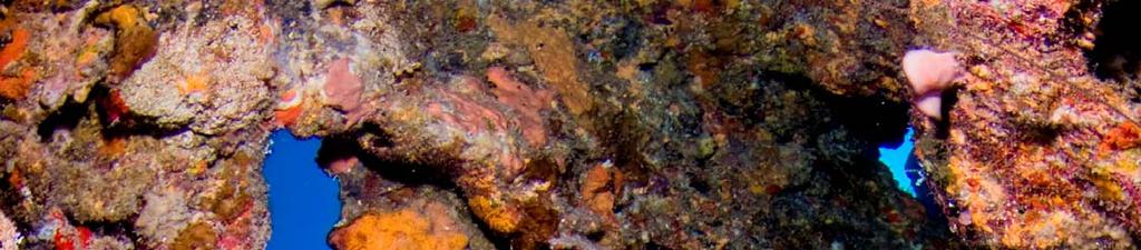
17 Unpacking & Disassembly A er removing your new Classic KISS from the crate, ensure that you have a DSV, 2 breathing hoses, 4 hose stubs, displays (if ordered), 2 counterlungs, and of course, the rebreather. First, various components will need to be disassembled in order to install the O Rings. Start with the counterlungs (if a ached); turn the counterlung a achment counter clockwise to loosen the lung and then remove it. Next, remove the top cap on the scrubber head. Remove the two large screws on the counterlung case shown in the photo, above right. Removing these screws will detach the scrubber head from the counterlung case. Unscrew the diluent add hose that runs from the LP manifold to the diluent add elbow. Undo the large brass draw nut that secures the scrubber canister to the scrubber head. There is a special tool for this job, but as it has been packed inside the scrubber canister you will need to find a subs tute. 17 MSL Jetsam/Classic KISS manual R.7
18 Once loose, remove the head from the scrubber canister. Inside the scrubber canister you will find 2 packages of O Rings, addi onal back plate bolts, large hose clamps, small lined clamps, ballast, and a spare counterlung ring. Set aside all the parts from the inside of the canister except for 1 bag of O Rings. From that bag, set aside the bags labeled mouthpiece and MAV These O Rings are spares. The unit comes with the O rings installed in the DSV, manual add valve, ADV and the displays. 18 MSL Jetsam/Classic KISS manual R.7
19 O Ring Installa on Using the O ring diagram at the back of the manual, separate the remaining O rings by size. The O rings that need to be installed are for the scrubber canister, exhaust valve, sensor cover, counterlungs, sensor/kidney plate and the draw nut. All other O rings have been installed. As with any piece of scuba diving equipment, the various components and O rings should be checked annually, and serviced as required. For those doing extensive diving, the various components and O rings should be checked more frequently. Servicing of your Classic KISS can be done by you, your dealer, or the parts can be returned to us. You are now ready to start installing the O rings. First, unscrew the counterlung a achments and the exhaust valve and remove them from the scrubber head. *NOTE: ALL O RINGS SHOULD BE LIGHTLY LUBRICATED!! DO NOT USE EXCESS AMOUNTS OF LUBRICANT; THE O RINGS SHOULD ONLY BE SLIGHTLY SHINY. The counterlung a achments take a 028 O ring around the threaded sec on. This O ring should be worked into the groove which is machined into the face of the a achment. On the other side of the counterlung a achment a 224 O ring should be installed. This has a larger groove than the 028. This O ring will need to be snapped into the groove. Once the O rings are installed, insert the counterlung a achment into the scrubber head and hand ghten. Ensure that you do not pinch the collar under the a achments. The collar should spin freely. The exhaust valve takes a 220 O ring which goes around the threaded area. This O ring seals the valve against the top of the scrubber head. Once the O ring is installed, rea ach the valve to the scrubber head by hand ghtening. When ghtening, hold the exhaust valve by the body. Do not force it by holding onto the valve adjustment. If you force it, it can pop past its adjustment latch and the valve may no longer be adjustable. Once rea ached, this valve should be run closed. *NOTE: Any damage to the valve, or any debris caught in the valve may cause a malfunc on &/or leak. Care should be taken when servicing the valve and also when filling the scrubber canister. Any of the absorbent material which falls into the center tube, can wind up inside the valve, if the diver turns upside down!! The scrubber draw nut requires a 114 & 111 O ring. The larger O ring should be installed against the face of the nut and the smaller should be stretched over the body and snaped into the groove. 19 MSL Jetsam/Classic KISS manual R.7


20 The scrubber head requires a 248, 250 & 223 O ring. The 248 O ring goes into the radial groove around the scrubber head. It must be carefully worked down and pressed into the groove. The larger 250 axial O ring gets pressed into the groove which forms a face seal. The final O ring for the scrubber head is a 223 which fits inside the scrubber tube and slides into the internal groove. Install the last 2 large O rings, a 248 and a 250 on the bo om of the scrubber canister. The 248 goes in the radial grove and the 250 in the axial groove. *WARNING: IT IS IMPORTANT THAT ALL O RINGS ARE IN GOOD CONDITION, THAT THE COMPONENTS ARE NOT DAM AGED AND THAT THE SEALING AREAS ARE CLEAN. IF THEY AREN T, THE O RINGS MAY LEAK CAUSING THE REBREATHER TO FLOOD. THIS MAY LEAD TO SERIOUS INJURY OR DEATH!!! ALSO, IF THE THREADED ROD IS DAMAGED, IT MAY BE DIFFICULT OR IMPOSSIBLE TO AT TACH THE DRAWNUT. IF THE DRAWNUT IS EXTREMELY DIFFICULT TO ATTACH, IT MAY PULL THE ROD OUT OF THE BOTTOM FIXTURE!! IF THIS HAPPENS, YOU WILL NOTICE THAT IT IS VERY DIFFICULT TO ATTACH AND THAT THE HEIGHT OF THE ROD HAS CHANGED! 20 MSL Jetsam/Classic KISS manual R.7
21 Assembly Once the O rings have been installed, the balance of the assembly can begin. Start with the ballast. Units are shipped with 8 stainless steel rings. 4 rings should be placed on each breathing hose. The weights can be moved up and down the hoses underwater for proper placement. With the loop hoses properly adjusted with no twists, and the ballast properly placed, the DSV will be weightless underwater! The ballast rings should be placed approximately a third of the way up the loop hoses if you are diving the older mouthpiece. For those who have the new BOV, the rings should be much closer to the actual mouthpiece as it is much lighter. A ach the mouthpiece to the hoses, and then li it so that it is level with the top of the unit. Look at the loop hoses; they should have a gentle curve. If they are twisted, adjust them by turning the end of the hose by the mouthpiece. These steps are important. If this isn t done, then the mouthpiece will be uncomfortable. The ballast rings will need to be adjusted again, once in the water. Posi oning will be different for every diver. While in the pool, your instructor will demonstrate neutral mouthpiece buoyancy. Ideally the mouthpiece will float neutrally in front of the divers face, if the rings are placed properly and the loop hoses are not twisted. If when doing this skill, the mouthpiece is not floa ng in the desired area, ensure that your hoses are not twisted and adjust your ballast rings. To adjust the hoses underwater, simply hold the mouthpiece with one hand, and gently turn the hose with the other. Again, once the rings are properly placed, they do not need adjus ng again. These steps are important. If this isn t done, then the mouthpiece will be uncomfortable. *NOTE: For the mouthpiece to be comfortable, the above instruc ons must be followed. If you feel the mouthpiece either pulling up or down while diving, adjust it by holding onto the mouthpiece and gently turning the hose by holding the end with your other hand. To assemble the scrubber canister, place the canister over the bo om cap and push down gently. While pushing, rock the canister slightly to ease the tube over the O rings. Once assembled, check the base to ensure that the O rings are not protruding. When secure, place the scrubber tube inside the canister. Rea ach the scrubber head to the counterlung case using the two large flat head screws. It should be securely a ached without over ghtening. Rea ach the diluent addi on hose. 21 MSL Jetsam/Classic KISS manual R.7
22 To a ach the scrubber canister, lay your Classic KISS, counterlung side down. See Page 25 for instruc ons on filling the scrubber. Slide the canister onto the scrubber head. When the canister reaches the first O ring, gently rock the canister back and forth un l the O ring is compressed inside the tube. If too much force is used, the O ring will dislodge and a leak will occur. If that happens, and the O ring is badly pinched, you may need to replace the O ring. An indenta on could cause another leak! Once the scrubber canister is pushed onto the scrubber head, insert the draw nut and start to hand ghten it. Once hand ght, stand the Classic KISS up and ghten using the KISS tool. A ach the hat. For those who wish to a ach a fourth sensor to read a dive computer, the port on the le hand side of the scrubber head can be used. *WARNING: Unless the le hand port is u lized, the two plugs must remain in place. Failure to do so, will cause water intrusion, &/or will cause gas to bypass from its intended path. Either of these could cause injury or death!! Once you have rea ached the scrubber canister and scrubber head to the counterlung case, you are ready to a ach the counterlungs. *NOTE: FOR EASE OF ATTACHMENT, A VERY SMALL AMOUNT OF LUBRICANT CAN BE AP PLIED TO THE INSIDE OF THE COUNTERLUNG OPENING. COUNTERLUNGS: The Classic KISS uses two back mounted counterlungs that are available in two sizes; 2 & 4 liter capacity. A combina on of these will normally provide a good match between the counterlung volume and the divers dal volume. Most divers will use a 2 and a 4 liter lung. Smaller people, including women, will normally use two 2 liter lungs and larger people, two 4 liter lungs. This allows for precise buoyancy control at any depth, including shallow water. Back mounted counterlungs leave the chest area clear and reduce the number of hoses and fi ngs compared to over the shoulder counterlungs found on other CCR designs. These lungs are inexpensive and easy to replace. To a ach the counterlungs, insert the lungs either through the top or bo om of the case. If required, the manifold can be popped off the case to make more room. To pop the manifold off, either pull up by hand, or use a flat screwdriver as a lever. It is supposed to be somewhat difficult to remove, so that it does not come off accidently during a dive. 22 MSL Jetsam/Classic KISS manual R.7
23 Push the counterlung onto the counterlung a achment firmly. Then using 2 or 3 fingers, start pushing at the top of the lung. This is to help push it into posi on. Move around the lung, clockwise, pushing firmly as you go. You are moving in small increments only, ensuring that you press on every part of the lung. As you get to the inside edge, it will feel like it will not a ach properly. Just keep pushing firmly, and con nue around the circle. It won t pop into posi on the first me around. Once at the top of the lung again, con nue to push, doing another circle. This me when you get to the inside edge, push a li le harder, and it should snap past the resistance point. This will get easier a er the first few mes. Ensure that the lung is pushed straight onto the a achment, and turn the ring clockwise to secure. When the counterlung is ght, there should be an 1/8 inch gap between the ring and the face of the counterlung, and the gap should be even. Do not apply excess force when ghtening the ring. It is not required and the ring will break. Using a tool to ghten this ring usually results in damage or breakage to the ring. Once a ached, secure the Velcro to the bo om of the counterlung case. *WARNING: IT IS IMPORTANT THAT THE LUNGS ARE PROPERLY SECURED TO THE BOTTOM OF THE COUNTERLUNG CASE USING THE VELCRO SUPPLIED. IF THE LUNGS ARE NOT SECURED, THEY WILL FLOAT UP AND BREATHING WILL BE DIFFICULT. EN SURE THAT THE LUNGS ARE PUSHED ON STRAIGHT AND THAT THE RINGS ARE NOT OVER TIGHTENED AS THEY WILL SPLIT!! DETERMINING THE CORRECT COUNTERLUNG SIZE: To determine if the counterlungs are a suitable size, first put the mouthpiece into your mouth, open the loop and inhale the gas into your lungs and then out of your nose un l the loop is completely empty. When the loop is empty, close the DSV without allowing any air to enter. Then, take a large breath, as much as you can hold, put the DSV into your mouth, open the loop and exhale all your air completely into the loop and then close the DSV. Ideally, the lung size should be as evenly matched to your own lungs as possible. If you find that when doing this test you can get more than one full breath into the loop before it is full, then possibly smaller lungs should be used. However, never use counterlungs where the volume is smaller than your own! Smaller people will find that they use a 2&2 liter, while most people will use 2&4 liter lungs. Larger people will use 4&4 liter lungs. In matching your dal volume to the counterlung volume, you will find that your buoyancy in shallow water can be excep onal. Only KISS divers can hold their posi on in water that is only 3 to 4 feet deep. If you are finding buoyancy difficult in water this shallow, this is due to either being new on the rebreather or the counterlungs are too large. While doing this test at the surface, remember that underwater your required volume won t change. If you find that your surface test went well, but it feels like the lungs are too small underwater, you probably have too much gas in the loop. To correct this, exhale some of the gas out of your nose. Or, you failed to a ach the Velcro to the bo om of the case and the lungs are floa ng up. This will cause either a decrease in lung volume &/or will increase the work of breathing. See the note at the top of the page. 23 MSL Jetsam/Classic KISS manual R.7
24 *NOTE: The closer you can match the counterlung volume with your own, the be er your buoyancy will be. Diving the Classic KISS with counterlungs that are too large will result in greater buoyancy changes. This can cause the user to lose control of their buoyancy which can lead to injury or death!! MANIFOLD: In the past, Classic KISS units were shipped with the manifold a ached to the counterlung case, via plate and screws. New units are now shipped with the manifold a ached to the case via a quick release system. This system allows the diver to pull up on the manifold to move it away from the case which would allow be er access to the counterlung area. The system is set up so that it is difficult to pull the manifold off. The system can be adjusted so that it is harder or easier to remove the manifold. This is done by adjus ng the set screws. Right to make it harder and le to make it easier. See the photo to the right. To a ach the manifold, line up the pins with the holes in the case, and push straight down. To remove, either hold the manifold under the edges and pull straight up. Or alterna vely, place a flat head screw driver between the manifold and the case and lever the manifold up. It is designed to be difficult to remove as we want to ensure that it does not come loose while diving. As this system caused the manifold to sit further back, a 11.5 inch hose is required for the ADV a achment. AUTOMATIC DILUENT VALVE (ADV): The ADV will add diluent gas to your breathing loop a er the loop volume has been reduced by either descending or breathing down the volume of oxygen. The diver will get the feeling that there is no more air in the loop to breath. All the diver needs to do is suck hard to trigger the ADV and it will feed him more gas. This is similar to the ac on of a second stage regulator. The ADV has been setup ght enough that it doesn t add diluent without the diver being aware. But it adds enough gas so that a reasonable descent rate can be maintained. Any me the ADV triggers you need to check your PPO2. you have either descended and compressed the gas in the loop or you have consumed enough oxygen to reduce the PPO2 significantly. This may also have caused you to lose buoyancy and descend. The posi on of the diver will effect the ADV. If the diver is horizontal or face down, the ADV will trigger easily. If the diver is ver cal, then it is more difficult to trigger. (A well fi ng harness is important; this will greatly reduce the difficul es of being ver cal in the water). Also, rolling to your right side, while horizontal, will assist in triggering the ADV. Diluent can also be added to the breathing loop via the mouthpiece. Simply go to open circuit mode, take a breath and then open the loop again and exhale the gas into the breathing loop. Another way to add gas to the loop via the mouthpiece is to close the loop only a 1/4 inch, for a second. You may need to lightly push the purge bu on on the front of the 2nd stage. A small amount of gas will blow directly into the breathing loop. 24 MSL Jetsam/Classic KISS manual R.7
25 Quick Disconnects The Classic KISS is shipped with the QR hose adapters already installed on the mouthpiece and the QR hose a achment towers already installed on the scrubber head. *NOTE: IN THE PAST, THE TOWERS WERE SEALED ONTO THE SCRUBBER HEAD AND WERE NOT TO BE REMOVED. THE TOWERS NOW SEAL WITH AN O RING. THE O RINGS HAVE BEEN INSTALLED FOR YOU. WHILE THE TOWERS ARE DIFFICULT TO TURN, IT IS STILL IM PORTANT THAT THEY ARE NOT ACCIDENTLY UNSCREWED WHILE REMOVING OR IN STALLING THE BREATHING HOSE. A LOOSE TOWER WILL LEAK!!! *NOTE: The old method of a aching the loop hoses to the quick disconnect hose stubs, required the black plas c ring and a standard hose clamp. In the past this method was required due to the lack of the quick disconnect system. As we now have the quick connect system and are not con nuously a aching and removing the hose clamps, we can move to a simpler and be er system. Our new system uses lined hose clamps, which have been designed to protect so hoses. As they are lined, we will no longer be shipping new units with the black plas c rings. If for any reason, the clamps are removed and a ached con nuously, the hoses should be inspected each me for wear and damage. The black plas c rings will be available with the original hose clamps, as parts sales only. The assembly procedure below shows how to a ach the original system. This new system is the same, except for the lack of the black rings. At this point, your ballast rings should already be in place. To prepare the QR system, the hose stubs need to be a ached to the breathing hoses. To do this you will need the 4 hose stubs and the set of 4 small hose clamps and plas c rings. You will also need the nut driver. Place a plas c ring and small hose clamp over the end of the breathing hose and push the hose into posi on on the hose stub. Ensure that the hose is pushed onto the hose stub as in the photo below. You can leave a space of 1 or 2 millimeters. Place the hose ring and hose clamp over the hose and hose stub, and secure. Repeat with the remaining 3 hose stubs. 25 MSL Jetsam/Classic KISS manual R.7
26 Finally to a ach the breathing hoses to the DSV, push the hose stubs onto the DSV hose adapters, push down and turn right. Repeat to a ach the other hose ends to the hose a achments. Use the same method to a ach the breathing hose to the QR hose a achment towers. Note that the a achment method is similar to opening and closing a child proof medicine bo le. *SERVICE: THE O RINGS ON THE HOSE STUBS AND THE CORRESPONDING SURFACES ON THE DSV ADAPTERS AND HOSE ATTACHMENTS SHOULD BE LUBRICATED ON A REGULAR BA SIS. PRIOR TO DIVING, ENSURE THAT HOSES HAVE BEEN PROPERLY ATTACHED TO THE TOWERS AND TO THE DSV!!! FAILURE TO DO SO COULD CAUSE INJURY OR DEATH!!! 26 MSL Jetsam/Classic KISS manual R.7

27 Tank/BCD Installa on To a ach the cylinders to the Classic KISS, first insert the large hose clamps through the slots on the counterlung case. Slide the tanks into posi on with the oxygen on the right and the diluent on the le and secure the first stages. Adjust the posi on of the cylinders: The handles should be out at the sides, parallel with the counterlung case so the diver can easily reach them when wearing the unit. The first stages should not be res ng on the counterlung case. Once posi oned, ghten the hose clamps using the enclosed nut driver. Once secure, turn the unit over and a ach the harness and wing. Any buoyancy compensa ng system can be used as long as it has bolt holes with 11 inch centres. The Classic KISS should be posi oned so that it sits as high as possible on the divers back. Also, the harness system should keep the rebreather ght to your back. If the unit is si ng low or loose, the work of breathing will increase. Finally, secure the manual add valve to the right shoulder strap or D ring. If the webbing straps are being used, they can be locked under the tank mount brackets on the case. Loosen the tank mount brackets, and instead of sliding the straps through the slots on the case, slide them under the tank mount bracket instead. Posi on the strap so that the buckle is located where you want it and then ghten the tank mount bracket again. This will keep the straps from sliding around while you a ach your cylinders. 27 MSL Jetsam/Classic KISS manual R.7


28 Changing The Scrubber The scrubber canister holds approximately 5.7 lbs of scrubber. It is an axial flow design which is resistant to channeling. The Classic KISS has one of the most efficient scrubber canisters on the market today. Please see our Scrubber Dura on page at the back of the manual for more details. The KISS units were tested using Sofnolime 797 grade; this is the brand we recommend. Changing the scrubber on the Classic KISS is an easy process. Start by removing the top hat and the large brass draw nut which secures the scrubber canister to the scrubber head and then remove the canister. NOTE: The inner scrubber assembly is a key part of the scrubber canister and care should be taken to ensure that it is not damaged and is working properly. 28 MSL Jetsam/Classic KISS manual R.7


 below the top edge of")
 below the tube.")


29 Plug the scrubber tube to prevent any scrubber material from entering it. This is very important as debris from the bo om of the canister can find its way back up into the exhaust valve and cause a LEAK! Fill the canister with approximately 5.7 pounds of absorbent to.75 inch (19 mm) from the top and install the top screen. While pressing down on the top screen, tap the outside of the canister with the handle of a screwdriver or similar tool. This will compress the absorbent. When installed properly, the top of the screen will be at least.75 inch (19 mm) below the top edge of the canister but no more than 1 inch (25mm) below the tube. A B C C B A Wipe away any dust from the top and inside edge of the canister and also from the outside of the inner tube. These surfaces, A, B, C, should be lightly lubricated. On the bo om of the scrubber head are three O rings, A, B, C, these should also be lightly lubricated. 29 MSL Jetsam/Classic KISS manual R.7
30 Gently, lay the canister down and push into place. Do this by keeping the canister square to the bo om of the scrubber head, and then gently push and rock it into place. This should keep the radial O ring from becoming dislodged. If you push the canister on crooked, this O ring may pop out of posi on. This is most likely to happen when the O ring is first installed. Once the canister has been in place for several hours or a few dives, it is unlikely that this O ring will easily be dislodged. If this O ring does get pinched, you may need to change it, as the indenta on could cause a leak! *WARNING: IF CANISTER O RING IS PINCHED AND THERE IS A LEAK, YOU WILL HAVE A SERIOUS FLOOD!!! THIS COULD CAUSE SERIOUS INJURY OR DEATH!! Lightly lubricate the draw nut O rings prior to installing and ghtening. Note that newer Classic models have a draw nut that does not require a tool. POSITIVE / NEGATIVE TESTING: Once the Classic KISS has been completely assembled, you are ready to do the posi ve and nega ve pressure tests. While these tests will give you the best indica on of any leaks in the system, it is s ll a good idea to do a quick bubble check when you enter the water. That s where buddies come in handy. *WARNING: IT IS VERY IMPORTANT THAT THE POSITIVE/NEGATIVE PRESSURE TESTS ARE COMPLETED AND THAT THEY ARE DONE PROPERLY. ANY LEAKS THAT ARE PRESENT ARE MOST LIKELY TO BE CAUGHT WHILE DOING THESE TESTS!! WHEN DOING YOUR TESTS, YOU SHOULD BE VERY CERTAIN THAT THEY PASS. IF YOU HAVE ANY DOUBT AND ARE UNSURE THAT THE TEST PASSED, YOU PROBABLY HAVE A SMALL LEAK. FIND IT!! THE KISS UNITS HOLD VERY GOOD POSITIVE AND NEGATIVE TESTS. To do the nega ve test, put the DSV into your mouth, turn the knob and inhale the gas from the loop into your lungs and exhale it out of your nose un l it is impossible to inhale any further. When the loop is empty, there should be no leakage into the rebreather and you shouldn t feel any extra gas sneaking into your mouth. If you don t feel any extra gas, close the loop while inhaling. The breathing hoses should be ghter as there is a vacuum in the loop. This will cause the DSV to sit higher than usual and the ridges on the hoses to be close together. If you watch the hoses while you are drawing the gas out of the loop, you will see how they constrict. Also, look at the counterlungs. They should be completely flat. Once you close the mouthpiece, watch the hoses and lungs closely. Don t look away. You need to no ce if anything changes, such as a slight droop in the hoses and/or the mouthpiece dropping or the lungs shi slightly showing that gas might be going back into them. Leave the loop closed for a few moments, 60 seconds is adequate, to see if the vacuum holds and then open the loop to let air back in. (Longer is not necessary and will damage the diaphragm.) 30 MSL Jetsam/Classic KISS manual R.7
31 The next most important part of doing your nega ve test (watching the lungs and hoses is the first) is when you release the pressure and open the mouthpiece. You should hear a whoosh as pressure is released. If you don t hear this sound, you have a leak! Or if the whoosh isn t as strong as it usually is, you have a leak. A er diving the unit for a while, you will learn what sound to expect when releasing the pressure. When you hear that sound, you will feel confident that you did a good test. If you have any uncertain feeling, then you may have a small leak. The exhaust valve should be fully closed during these tests. *WARNING It is important to not leave the vacuum in the loop for more than a few moments as this will cause the ADV diaphragm to stretch and get baggy. If this happens, the ADV will not work properly. It will either stop working altogether or will con nuously feed the diver diluent. *NOTE: When doing your test, it is VERY important to not suck so hard that you are damaging the diaphragms. When you do the nega ve test, suck un l you get a good seal, and then immediately close off the BOV. if you suck so hard that you feel the pressure building in the back of your throat/neck area, your ears pop, or you feel your face turning red for exer on, this is way too hard. There is no need for this and it will damage the valves and diaphragms. Suck just un l you feel that pressure, then close the valve. Our new BOV has a larger bore and much be er work of breathing then the older DSV. In order to get that good work of breathing, the valves are more flexible. This means that with this new product, we need to ensure that we have good tes ng habits. Those divers who learned the tes ng procedures years ago, have to understand that the equipment has now changed, and that our habits must also change. Also ensure that the area where the valve seals is clean. build up in this area will cause the diaphragm to leak. *NOTE: if the unit is failing pressure tes ng due to a replaced ADV diaphragm, ensure that proper diaphragm installa on procedures are followed. This is very important. Please see page 58. To do the posi ve test, ghten the exhaust valve by turning it fully clockwise. Put the DSV into your mouth, turn the knob and exhale into the loop un l you hear the exhaust valve release. Alterna vely, open the diluent tank valve and press the bu on in the centre of the ADV cover. The counterlungs should be expanded to their maximum size. Once inflated, close the diluent tank valve, and press the bu on in the centre of the ADV cover to vent the gas in the hoses from the diluent tank. Listen carefully for any air leaks and ensure that the counterlungs remain firm for at least five minutes. The oxygen tank valve and mouthpiece should be closed during these tests. A er the test is complete and you open the DSV, again you will hear the sound of the pressure being released. This is important! 31 MSL Jetsam/Classic KISS manual R.7


32 32 MSL Jetsam/Classic KISS manual R.7


33 Sensor Installa on *WARNING: THERE ARE VARIOUS DISPLAY SYSTEMS AVAILABLE FOR THE KISS REBREATH ERS. THEY INCLUDE, BUT ARE NOT LIMITED TO THE JETSAM TRIPLE DISPLAY, AND SHEAR WATER. As with all electronics, these components must be treated with care and respect. This includes taking care to not drop, bang, or roughly handle them. Also, do not leave these components in a hot environment, such as a car or direct sunlight. The heat &/or sun, can and will damage any electronic components. The Jetsam triple wrist display and the Shearwater products both use K 22D sensors. The unit price does not include sensors. Should you wish to order them from KISS Rebreathers, they will need to be added to the order. Prior to installing them, it is best to open the bags and let them sit for at least 24 hours prior to calibra on as they need to go through a wake up period. Ideally, open the bags about a week prior to use if possible. New sensors will read low when first installed and will creep up slightly over the course of a week or so. A er that, they seem to be stable for months on end. Don t waste me calibra ng the sensors if they are reading within a 1/2 percent. These sensors should last for at least 1 to 1 1/2 years, if they are not damaged or abused. Oxygen sensors work on the same basis as a ba ery. The more that they are used, the more o en they will need to be replaced. An easy way to remember your sensors anniversary date is to write the date on the bag when you open it, and keep the bag in safe place. The K 22D sensors are safe to dive if the millivolt reading is between 9 and 13, AND they can be calibrated in both air and oxygen. The Shearwater products will read the millivolts of the sensors or a volt meter can be purchased at your local hardware or electronics store. *WARNING: It is extremely important that the sensors millivolt readings are in the correct range, and that they can be calibrated in both oxygen and air. If even just one of these 3 items doesn't comply, DO NOT DIVE!!!! Failure to ensure that the sensors are working properly, can result in serious injury or death!!! *WARNING: On the following pages are the calibra on instruc ons for the displays systems. It is essen al that the calibra on procedures are followed properly. Failure to do so can cause injury or death!! First, remove the hat from the scrubber head. Then, remove the 6 screws securing the kidney using a 5/32 alan wrench. Li the kidney off the scrubber head. 33 MSL Jetsam/Classic KISS manual R.7


34 The sensors fit into the three wells underneath the kidney. Remove the O rings from the sensors as they are not needed. Removing the O rings from the sensors will enable you to screw them slightly further into the well which will slightly improve the response me. Drop the sensors into the well, connector side up and turn into place. Ensure that they are turned all the way in. The sensors should be turned in un l they are snug, but they shouldn t be excessively ght. You may wish to use needle nose pliers to aid you in securing them. *WARNING: It is important that the sensors are properly installed. If the O ring is le on, or they are not turned all the way into the head, the response mes may be delayed!! 026 O-rings Once the sensors are in place, install the 026 O rings around the boses on the kidney plate. Then, secure the Molex connectors to the top of the sensors. *NOTE: Ensure that the O rings are in good condi on, that the area is clean and the components are not damaged. Replace the kidney plate on the scrubber head, ensuring that the wires are not pinched under the plate. *WARNING: If the wires are pinched under the plate, the scrubber head will not be water ght. Water damage in this area will ruin the sensors and/or the electronics. If the wires do get pinched, inspect them for damage!! Using a 5/32 Allen wrench, secure the 6 screws which hold the kidney plate in place. *WARNING: Do not over ghten the screws that secure the kidney plate as the head can be stripped. Use just 2 fingers on the Allen wrench to ghten. Remember, you just need to squeeze the O rings to seal!!! 34 MSL Jetsam/Classic KISS manual R.7
35 JETSAM TRIPLE WRIST DISPLAY The Jetsam triple wrist display is a triple redundant system with each display having it s own case, cable, ba ery and circuitry. Each display will read an individual oxygen sensor. This display will show the PPO2 of the oxygen. That is it s only func on. The divers that prefer this display are those who truly want to Keep It Simple and appreciate the triple redundancy. Things to remember with this display is that the back port must be closed prior to jumping into the water and also any water must be tapped out of the display prior to opening the port as well. A single drop of sea water on to the board will damage it. Do not use compressed air! Those who are mechanically inclined will find that they are able to service this display themselves; Others may find it challenging. But servicing, if required can be done by the dealers or by sending in the parts to head office. To turn the displays on, rotate the dial on the back, clockwise. To calibrate the original KISS displays, the dial will need to be turned counter clockwise while pushing the lever to the right. The lever must be pushed over in order for the dial to be turned in this direc on. Once in this posi on, a small port will open to allow access to the meter. Insert the jewellers screwdriver into the port and gently turn the screw to adjust the reading. 35 MSL Jetsam/Classic KISS manual R.7
36 *WARNING: When inser ng the screwdriver into the port to adjust the meter, DO NOT PUSH THE SCREW DRIVER INTO THE ME TER WITH FORCE. GENTLY PLACE THE TIP OF THE SCREWDRIVER INTO THE ADJUSTMENT SCREW ON THE METER. *WARNING: A er diving, gently tap the display on your thigh to remove any water trapped in the back of the display before opening the calibra on port. A single drop of salt water on the electronic board or meter will ruin them!!! Gently means, do NOT use compressed air!! *WARNING: The PPO2 display cases have internal magnets. Divers should not wear a compass on the same wrist or near the displays as the magnets will cause the compass to read incorrectly. *SERVICE: Note that the display backs are disposable and are not meant to be serviced. The displays should be calibrated with oxygen. The procedure for this, is as follows: 1. Ensure that the diluent and oxygen tank valves are closed. 2. Draw all of the gas out of the loop. Do this by pu ng the DSV into your mouth, open the loop, inhale the gas into your lungs and then exhale it out of your nose. *Note: it is important that you do not exhale any gas back into the loop while doing this. 3. With the loop closed, open the oxygen tank and press the manual add valve bu on, adding oxygen into the loop un l the exhaust valve burps. (the exhaust valve should be fully closed) 4. Repeat steps 2 & 3 un l the loop has been completely flushed with oxygen. This usually takes 3 to 4 flushes. 5. Once the loop has been completely flushed, close the oxygen cylinder and open and close the mouthpiece quickly to bring the gas in the loop to ambient pressure. With the loop closed, calibrate to The readings should be verified with air. To verify with air, first ensure that both tank valves are turned off. Then, remove the loop hose which is a ached to the exhaust side of the mouthpiece. Put the mouthpiece into your mouth, open the loop and breathe. This will draw fresh air through the loop and eliminate the pure oxygen which you flushed the loop with. It will take a few minutes for the oxygen percentage to drop. Once the displays have been calibrated, close the calibra on ports on the back of the displays. *WARNING: DO NOT FORGET TO CLOSE THE CALIBRATION PORTS ON THE DISPLAYS. THE DISPLAYS WILL NOT BE WATER TIGHT WITH THE PORTS OPEN!! The KISS rebreather should be flushed with oxygen on every dive to ensure that the displays are reading correctly, and re calibrated every me the absorbent is changed. 36 MSL Jetsam/Classic KISS manual R.7
37 ORIGINAL JETSAM DISPLAY BATTERY WARNING!! The ba eries used in the displays are Duracell PX28L 6 volt camera ba eries or equivalent. DO NOT SUBSTITUTE ALKALINE BATTERIES! These ba eries should be replaced any me the backligh ng will not turn on, every three months, or more o en. Do not a empt to use the ba eries to the failure point. *WARNING: WHEN THE BATTERY VOLTAGE DROPS, THE DISPLAY READS HIGH. THIS IS A PO TENTIALLY DEADLY SITUATION. IF THE DISPLAYS HAVE BEEN ACCIDENTALLY LEFT ON FOR AN EXTENDED PERIOD THE BATTERIES MUST BE REPLACED. Make a note of the installa on date of the ba eries. Also note the number of hours each ba ery is used. Your life depends on the accuracy of the sensors, ba eries, and displays. With the backligh ng enabled the displays will operate for 20 hours a er which the backligh ng will become dim and fade out. The display will con nue opera ng for another 20 hours before it fails. If the backlight op on is selected but the light does not come on CHANGE THE BATTERIES! DO NOT GAMBLE AND GUESS THE AMOUNT OF TIME YOU HAVE LEFT!!!!! To change the ba eries, remove the four outer screws on the back of the display case and carefully remove the cover. A er changing the ba ery and logging the date, ensure that the o ring is LIGHTLY lubricated and clean prior to replacing the cover. 37 MSL Jetsam/Classic KISS manual R.7


38 Replacing Ba eries/meters/circuit Boards The following instruc ons are for replacing the ba eries, meters (LCD read out) or circuit boards. Note that these instruc ons are for replacing the circuit boards with the plug in wires. Before you start, ensure that your work area, tools and your hands are clean and dry. This is quite important as a single drop of sea water will ruin your electronic display. Take the display and with the calibra on port side down gently tap the display on your thigh to remove any water droplets that could s ll be on the display back. GENTLY!! Even if you have been out of the water for some me, you should s ll do this. *NOTE: Water should be tapped out when ever the case is opened or when the calibra on port is opened. Do not use compressed air! Place the display port side up on the table and remove the 4 outer screws on the display that you wish to service. You will need a Philips screwdriver. As you are removing the screws try and remember how ght they are. The case is sealed by an O ring and the screws should not be over ghtened. When you close up the case again, this will assist you in sealing the case properly. The wire will need to be removed from the back of the circuit board. To unplug it, gently pull the black plug towards the wire. Once the wire has been unplugged, the circuit board can be removed. Pull it straight up and out. It will be snug. If you like, you can use a tool such as a dental pick to assist you or one of the small jewellers screw drivers from your tool kit. HOWEVER, be very careful that you do not damage the circuit board!! Replace the ba ery, meter or circuit board, as required. 38 MSL Jetsam/Classic KISS manual R.7


39 Once you have repaired or replaced the required parts, insert the circuit board back into the case. Push firmly, straight down while ensuring the wire is not pinched on the side. Once in place, plug the wire back in. Use a ny screwdriver to push the wire into the side of the board, by where it comes in. Also, keep wire on bo om side of Souder bump located at the top le side of board. This will help keep a small amount of pressure on the connector, so it doesn t come undone. Now you are ready to install the O ring. Check it for nicks and indenta ons and if you find any, discard the O ring and install a new one. If you dent the O ring while re a aching the display back, discard it and use a new one. *NOTE: This is important as a flawed O ring will allow water to enter the case!! Apply lubrica on generously to the O ring. The lubricant will help the O ring remain in place and will also assist in posi oning the display back properly. Lubricant should also be applied to the raised edge, on the inside of the display back. This will ensure that the raised plas c slides past the O ring without catching it. Replace the O ring in the case. If you are reusing an O ring, it will have kept its shape. It can go back into the case in the same orienta on that it was in before. The lubricant will assist in keeping it in posi on. Place the back on the display case. Ensure that you have placed it correctly with the calibra on port in the correct posi on. You will need to push it firmly down into posi on and must be able to hold it in place while you insert and ghten the screws. This is easiest to do by pushing down on the back, standing and using your body weight to help hold it in place. Place the screws in the holes and turn them slightly counter clockwise un l you feel them drop into the old threads. Then ghten the screws un l the back is secure and seated properly. While it is important that the screws are ght enough, it is also important that they are not over ghtened. Remember, the O ring creates the seal. 39 MSL Jetsam/Classic KISS manual R.7


40 Replacing A Single Display Case In order to remove the clear cover, you will need to remove the back from the case, as well as the case next to the one you are working with. If you are working with the middle case, you will need to remove all 3 display backs. To change the clear display cover, start by following the direc ons on page 38.. As well as having the display backs off on the case that you would like to change, the O ring, wire and circuit board assembly must be removed. The strain relief/wire assembly will need to be removed from the clear cover. This is done by loosening the hex nut on the strain relief which is closest to the case. Once it is loose, the wire/strain relief assembly can be removed. *NOTE: Do not touch the other nut on the strain relief. This is used to a ach the strain relief to the wire. Generally, a strain relief can only be used once. If you loosen it or remove it, it should be replaced. Also, it is normal for the 2 nuts to have a gap between them. Lay the displays on the edge of your work table. The case to be removed should be si ng over the edge. With a rubber mallet, gently tap the case in the area where it is a ached to the second case. See above right photo for the correct tapping loca on. If you tap on any other part of the case, use too much force or twist it, you can damage the case which could cause breakage at a later date. 40 MSL Jetsam/Classic KISS manual R.7


.")


41 To a ach a new clear display cover, rea ach the strain relief and wire first. First, twist the wire counter clockwise 6 to 8 full revolu ons. Then insert into the clear cover and ghten by hand. Insert the wire through the hole on the case. Secure the strain relief to the case. Tighten by hand first and then using a wrench, turn it another 1/2 to full turn more un l seated. Twis ng the wire prior will ensure a straight wire once you have finished reassembling the display case. Apply lubricant to the puzzle pieces which join the displays together and then push the pieces together by hand. (ensure that you have them oriented the correct way). You should be able to push them about 1/8 to 1/4 inch together. Then, lay the cases on the table and gently tap with a rubber mallet un l the edges on the back are even. Tap gently in the area where the cases join. See photo. WRONG!! WRONG!! *NOTE: Only tap the cases by the puzzle pieces, as per above instruc ons. If you tap the cases on the outer edges, as shown in the two above photos, you will stress the plas c. This will cause breakage. Following the direc ons on page 39, insert the circuit board assembly into the case, rea ach the wire to the board, insert the O ring and seal the case. 41 MSL Jetsam/Classic KISS manual R.7


42 Replacing the Wire Remove the spiral wrap and set aside. Then, following the direc ons on page 38, prepare your work area, remove the display back, unplug the wire, remove the circuit board assembly and then the strain relief/wire assembly from the clear cover. To remove the wire from either the Classic KISS sensor plate or the Sport KISS three hose connector, you will need to remove the white molex connector. To remove the molex connector, push down on the two gold contacts as shown in the upper le photo. You will need to use a small tool such as a dental pick. Gently pull the wire out as you are pushing down. Take note on how the connector comes out of the contact. It will need to be a ached in the same way. Also make a note on what posi on each wire is in. If you rea ach the wires backwards, you will have a sign in front of your digital PPO2 read out. Now you are ready to remove the wire from the Classic KISS sensor block. Remove the strain relief on the wire which you wish to change. Your new wire will already have the strain relief a ached to it. Hand ghten on to the sensor block and then using a wrench ghten another 1/2 to full turn, un l seated. In this applica on, you can use the second nut on the strain relief to ghten the wire to the senor block. It is easier to access with a tool and will not damage the strain relief. Ensure that the strain relief is threaded in straight. The bo om of the hex nut should be flat against the area where it is seated against. Once the wires have been secured to the sensor block, the other end can be a ached to the display case. First, twist the wire counter clockwise 6 to 8 full revolu ons. Then insert into the clear cover and ghten by hand. For the last 1/2 to full turn, use a wrench and ghten un l seated. Twis ng the wire prior will ensure a straight wire once you have finished reassembling the display case. Follow the direc ons on page 39 for reassembling the case properly. 42 MSL Jetsam/Classic KISS manual R.7
43 Display Troubleshoo ng FLICKERING OR FLUCTUATING DISPLAYS: Your displays may flicker slightly on the surface with no sensor a ached. This is normal. It is called random noise. On the surface with a sensor a ached your displays will also fluctuate. This is normal. Once diving or breathing on the unit the displays will stabilize and act normal. What is normal? Showing a gradual PPO2 drop as you metabolize the gas in the loop. The more you dive your KISS rebreather, the sooner you will learn how the oxygen sensors act. If the displays are fluctua ng during a dive this could mean the sensors are old, the ba ery needs to be replaced, the wire could be damaged or the magnet isn t registering (some of the older display backs had this problem). HARD TO CALIBRATE: The poten ometer (PPO2 adjustment screw) is turned all the way in one direc on. You will need to do at least one full turn, maybe two in the opposite direc on and then try and calibrate again. The sensor or ba ery may be old. PPO2 READ OUT IS ZERO OR 1: If the read out is 1 then sea water has come in contact with the circuit board and/or meter. Any parts that have come in contact with sea water must be replaced. If the read out is zero, then it could also be a dead sensor. DETERMINING THE PROBLEM AREA: To determine where the problem lies, first take the sensor from the faulty display and swap it with a func oning one. Did the problem follow the supposedly faulty sensor? If yes, the sensor is bad. If the display s ll does not work, then it probably isn t the sensor. Next, swap the meter with a func oning one. Again, did the problem follow the meter? Or is the faulty display s ll not working? If this is the case, the circuit board could be bad. If the meter is working on a known good display, it might be ok. When sea water comes in contact with electronics, even if it is just a small amount it is difficult to determine where and how bad the damage is. It could even be in the wire. When in doubt, change the wire, circuit board and meter. 43 MSL Jetsam/Classic KISS manual R.7
44 SENSORS When you open up your new K 22D sensors, they will have a millivolt reading between 9 and 13 millivolts. As per Vandagraph., as long as they are in that range, they are safe to use. *WARNING: You also need to ensure that they can be calibrated in Oxygen and that they read correctly in air. This is very important. Even if a sensor is reading in the proper range, as it ages you may no longer be able to calibrate it properly. ***IF THIS HAPPENS, THE SENSOR MUST BE DISCARDED. FAILURE TO USE A PROPER SEN SOR WILL CAUSE SERIOUS INJURY OR DEATH!!!!!!!!!! In diving applica ons the sensor will last one to 1.5 years, depending on how o en you dive and how they are stored. Sensors should be allowed to dry out a er your day of diving, especially if you are diving in a humid environment. This means that you need to leave the loop hoses or scrubber canister off overnight to allow air to circulate through the scrubber head. Leaving the unit sealed up will not allow the condensa on to evaporate. ***If the Classic KISS has moisture in the head from diving or from being in a humid environment, and it is then sealed up ght, the wires from the end of the display will start to corrode!!!! If this happens, whatever display or computer you are using, will not work properly!!!! It is extremely important that the head is allowed to dry out if the unit is to be sealed up. This means that a er a dive trip, don t just drop the unit on your work bench and walk away from it!!! At the very least, drop the canister and let the head dry. This will help keep your wires in good working order. Sea water on the sensors will probably cause them to fail. As your sensors start to age you will no ce that they are harder to calibrate, slower to react and will dri more a er calibra on. Electrolyte, which is a gel like substance is inside the sensors. If you no ce this substance leaking out of the sensors, do not touch it as it is caus c. Do not dive with a leaking sensor. The readings will be high!!!! 44 MSL Jetsam/Classic KISS manual R.7
45 CARE FOR YOUR FISCHER CONNECTOR AND THE CABLES Having Fischer connectors on a rebreather display system is a convenience that many divers enjoy. While a lot of maintenance is not required, some care is important in order to ensure that they operate properly. The Fischer connector port is water ght and any water that gets in to the port cannot harm your plate, computer, HUD or pendent. However, should sea water get inside the port or the ends of your linking cable, flush them with fresh water as soon as possible a erwards then leave them to dry completely BEFORE refi ng the cap. Regular maintenance should include: 1. Inspect the connectors and look for any signs of corrosion; parts will start to turn green. 2. If you see green/corrosion, rinse the connectors briefly with white vinegar and use a fine toothbrush to remove the build up. Rinse well and let dry completely before refi ng the protec ve caps. 3. Keep the inner O ring lubricated by either applying a SMALL amount of grease on the metal end of the cable end that slides into the computer fischer connector to lubricate the inner O ring of the bulkhead connector. Filling the connector with food grade mineral oil once a year will also work. This will serve to improve the seal and make the connec on more reliable. If you have a sensor which is reading erra cally, this could be a solu on. If you use the mineral oil, drain any excess prior to replacing the caps. 4. Use the protec ve caps. The caps will help keep your connectors clean, keep the lubricant in and any debris and water out. Remember, the cleanliness of the contacts is essen al to the integrity of the link. Following these simple steps will ensure that your system works properly. Look a er your cable and connectors and they will look a er you. 45 MSL Jetsam/Classic KISS manual R.7
46 SHEARWATER HUD SHEARWATER WARNING Never risk your life on only one source of information. Use a second computer or tables. If you choose to make riskier dives, obtain the proper training and work up to them slowly to gain experience. This system will fail. It is not whether it will fail but when it will fail. Do not depend on it. Always have a plan on how to handle failures. Automatic systems are no substitute for knowledge and training. No technology will keep you alive. Knowledge, skill, and practiced procedures are your best defense. (Except for not doing the dive, of course.) SHEARWATER PRODUCT CONFIGURATION Shearwater Research Inc. designs and builds both computers and HUD s (Heads Up Display) for rebreather diving. To secure either computer or HUD to a Classic KISS, a dual fischer sensor plate must be used. These systems a ach to the KISS rebreathers via the KISS dual fischer plate. There are two cable op ons with the computers: 1. The computer can be ordered with a dual fischer cable. This means that at either end of the cable is a fischer connector. One to plug into the Classic KISS sensor plate; the other to plug into the computer. 2. The computer can be ordered with a single fischer cable. This means that at the computer end, the cable is hard wired into it. At the other end is a fischer which is secured to the Classic KISS sensor plate. For further informa on on the Shearwater computers, please contact your local Shearwater dealer. There is one cable for the HUD; it has a fischer at the sensor plate. INTRODUCTION TO THE SHEARWATER HUD In order to explain the logic behind the design of the Shearwater HUD, we have included their introduc on in this write up. The logic of the Shearwater HUD is as follows: 46 MSL Jetsam/Classic KISS manual R.7
47 The first point to consider is, there are bad alarms and good alarms. For example a fire bell is a bad alarm. It is bad because the absence of a ringing bell doesn t mean there is no fire. It just means the alarm isn t ringing. The fire bell may not be ringing because the ba ery is dead, the smoke detector isn t in the right place, the installer screwed up the installa on, there is a foreign object stuck in the ringer, etc. It doesn t mean that everything is ok. A good alarm is one where there is an obvious difference between the lack of func on and the lack of an alarm. A solid green light doesn t do that. The second point to consider is, there are integrated HUD s and redundant HUD s. Integrated HUD s can no fy you for features such as deco ceilings and distance from set point. But they can t do that and be redundant also. If you wish to have redundancy, then the HUD needs to be calibrated separately and it can t display deco informa on unless it has a separate decompression computer with its own set of ssues, gases, etc., built into it. The third point to consider is that there are HUD s that just display the set point or PPO2 of the gas in the rebreather. This version is very useful for scootering, low visibility, filming, and manually maintaining set point. With the Shearwater HUD, we tried to find the best of all worlds. It displays the PPO2 only, which makes it a redundant PPO2 meter. Since it uses three LED s simultaneously, it can display them quickly. A typical 1.3 takes about 2 seconds to read. A er a few dives, many divers have said that they do not need to consciously read the displays; they look at the display and their brain recognizes the number of flashes. When there is a problem with a sensor, it is no ceable immediately as one of the LCD s flashes different from the others. As the diver knows what to expect, when something different happens it really jumps out at them. The Shearwater HUD does not display con nuously; there is usually 5 seconds between the displays. Also, as the PPO2 gets farther from 1.0, the light DENSITY gets higher. If you are more than 0.50 away from 1.00, the power is turned up to the high intensity LED s; so they get brighter! At 0.20 you have three very bright red LED s flashing just about con nuously in the corner of your eye. OPERATION The HUD has a single bu on on the box, which is used for powering on/off, and calibra on. Power On/Off: One push of the HUD bu on will turn the HUD on, while one subsequent push will turn the HUD off. Calibra on: The Shearwater HUD calibrates only to oxygen; 0.98 to be exact. This allows for imperfect oxygen flushes and water vapour. To calibrate, push the HUD bu on three mes within 1 second. This may take a li le prac ce, but it is intended to prevent accidental calibra ons. Once you successfully do the calibra on sequence, all three lights will come on bright red for 5 seconds. If this doesn t happen, then you didn t do the calibra on command successfully; try again. DISPLAY DESCRIPTIONS A er calibra on, each of the sensors should be flashing one orange. That means the PP02 is between 0.95 and Remember, the actual value it uses for calibra on is MSL Jetsam/Classic KISS manual R.7


48 If a sensor fails calibra on, it will flash one red and one green. It can be useful to look at the millivolts on your alternate display to see why a sensor didn t calibrate. In these two example pictures, sensor one has failed and is alterna ng between red and green GENERAL FLASH PATTERN: The number of green flashes is the number of tenths above 1.0. Therefore, 3 green flashes is 1.3 PPO2. The number of red flashes is the number of tenths below 1.0. Therefore, 2 red is 0.8 PPO2 Example: 0.80 is RR RR RR 0.20 is RRRRRRRR RRRRRRRR RRRRRRRR 1.3 is GGG GGG GGG You will no ce from the above example s that the farther away from 1.0, the shorter the interval between flash sets. BATTERY WARNING: When you turn the HUD on, if it flashes orange for 30 seconds, this indicates a low ba ery. The ba ery is contained in the box with the processor. To change the ba ery, you will need to remove the top cover. Replace the ba ery with a 3.6 volt Lithium Sa Ensure when replacing the cover that the O rings are properly secured, cleaned and lubricated. It would be beneficial to carry a spare ba ery in your spares kit, as they aren t available in some remote areas. This should not be a cause for concern as the ba ery should last many months, even years. REBREATHER ATTACHMENT The box should be a ached to the loop hose, behind the divers head. Use the enclosed Velcro for this. In this loca on it will not be in the way and it is also possible to reach the bu on. A ach the HUD e to either side of the BOV. It is handy to a ach it to the le side so that dumping the right loop hose a er a dive isn t effected. Wrap the cable for the HUD around the loop hose, and then snap on to the a achment. The HUD a achment consists of 2 pieces; one part a aches to the BOV with the e and the other the HUD snaps into. The two parts are joined by magnets. These are extremely strong magnets! Slide magnets apart and back together only. 48 MSL Jetsam/Classic KISS manual R.7
49 Manual Add Valve/Metering Orifice The manual add valve is for adding oxygen to the loop. The o rings should be changed annually or if the flow rate changes, more frequently. The inlet of the valve is protected by a 15 micron filter. This filter will NOT stop seawater from contamina ng the orifice. All components in the add valve must be clean, oil free, with the o rings lightly lubricated with oxygen compa ble grease. The tools required to disassemble the valve are a wrench or alan key, small snap ring pliers and a jewellers screwdriver. First, insert the snap ring pliers into the snap ring on the bu on end of the valve and remove. Remove the nut with either the wrench or alan key, depending on which nut you have; pull out the spring. The spool and orifice are all that is le inside the valve. A C B D E DO NOT SCRAPE OR GOUGE THE BORE!!!!!! To remove the spool and orifice push in the bu on using a jewellers screwdriver. This will force the spool and orifice out the other end. When you have the spool removed, cut the old o rings away with a sharp knife and replace them with new V O rings which have been lubricated with an oxygen compa ble lubricant such as Christolube. Do not scratch the O ring grooves. The orifice does not need to be removed unless it is damaged or plugged. The parts in the valve are: A. snap ring; B. nut; C. spring; D. spool & orifice; E. valve body 49 MSL Jetsam/Classic KISS manual R.7
50 *WARNING: When reassembling the valve, ensure that you do not over ghten the nut. Remember, when screwing any metal screws into plas c use only two fingers on the wrench. If you over ghten the nut, it will strip the threads and the valve will leak. When a aching the valve to the filter and the hoses, it is very important that you use a second wrench to hold the nut next to the valve body in place. Do not allow this nut to spin as it will over ghten and strip the plas c. This will cause the valve to leak. The valve body is not a subs tute for a wrench. Older Classic KISS units were shipped with the Swagelok SS/Teflon hoses. New units are shipped with the Miflex hoses. When a aching the manual add valve to these hoses, remember that the inlet port is the one nearest the add bu on. The hose which is a ached to the oxygen first stage is a ached to the inlet port. *NOTE: The oxygen delivery system a aches to the rebreather via the elbow on the side of the scrubber head. Please note that the male end of the elbow which screws into the head is NPT, or pipe thread. This is a tapered thread, NOT a straight thread. If you screw a fi ng with a straight thread, such as a swivel elbow, into this port, it will damage the rebreather head! If this happens, it is NOT repairable. Prior to modifying your rebreather, please be certain that you understand what fi ngs are required. *NOTE: The Miflex hoses are tested and rated for oxygen use. As they have standard regulator hose fi ngs, they can be replaced with other rubber LP hoses. If you do so, please ensure that the hoses you use are rated for oxygen use!! Also, all low pressure hoses on the Classic KISS should be inspected periodically to ensure that they are not damaged and in good working order. This includes the oxygen hoses, diluent hose, DSV 2nd stage regulator hose, ADV hose. The KISS rebreathers are mechanically controlled. The oxygen manual add valve houses a orifice which allows oxygen to flow into the loop at all mes. In the event that more oxygen is required, the bu on on this valve will need to be pushed. The difference between diving a KISS rebreather manually and other rebreathers is that the constant flow of oxygen keeps our divers from ge ng too busy underwater. Diving other rebreathers manually means that the only way oxygen gets into the loop is by pushing the bu on. What does this mean to the diver? It means that when you get to your maximum depth, you will adjust your PPO2 and then unless you are working hard or going up and down in the water column, you will only be pushing the bu on every 10 to 20 minutes. This depends also on where the constant flow has been set. If you find yourself pushing the bu on all the me, then you need to increase the flow. If you find that your oxygen is creeping up during normal diving ac vi es, then you will want to decrease the flow. 50 MSL Jetsam/Classic KISS manual R.7


 to this line.")
51 Adjus ng the O2 Flow Rate The oxygen injec on rate can be adjusted to suit each individual diver. The required flow rate depends on the physical size of the diver and the degree of exer on used during the dive. If the flow rate is too high the P02 will climb to dangerous levels and the breathing loop will have to be purged to reduce the oxygen par al pressure to a safe level. If the flow rate is set too low oxygen will have to be manually added more o en during the dive. TOO LOW IS BETTER AS IT IS QUICKER TO ADD OXYGEN TO THE LOOP, THEN TO FLUSH IT!! To adjust the flow rate, disconnect the oxygen delivery line where it a aches to the stainless steel elbow on the side of the scrubber head. A ach a 0 1 litre per minute flow meter (Dwyer VFB 60 SSV or equivalent) to this line. Disconnect the manual add valve supply line where it a aches to the add valve filter and connect a psi gauge between these fi ngs. A B Remove the clamp ring from the oxygen regulator, (A) and li the black plas c plug, (B) out of the regulator cap. Connect the regulator to an oxygen cylinder which has at least 800 psi remaining. Slowly (oxygen, remember) open the oxygen valve. Note the gauge pressure and flow meter reading. The rela onship between the pressure se ng and the O2 flow rate should match the table on the following page. For those of you using the Miflex hoses. The following photos show how the flow system can be checked and which parts you need. All parts can be purchased through one of your local fi ngs suppliers. This is just one method that can be used. First, remove the miflex hose from the filter and a ach an IP gauge. Determine where the IP is set, before you make any changes. A er you record that informa on, rea ach the hose. Then remove the miflex hose which is a ached to the plug side of the valve. A ach your flow meter and short LP hose (see above photo). As per the instruc ons on the next page, adjust your flow. Once you have adjusted the flow, you can remove the flow meter and hose, and rea ach the IP gauge. This will allow you to verify your flow reading with the IP of the first stage, using the chart on the next page. NOTE: IT IS VERY IMPORTANT THAT TWO WRENCH S ARE USED WHEN REMOVING HOSES OR FITTINGS FROM THE MANUAL ADD VALVE!!! ONE MUST BE USED TO ENSURE THAT THE FITTING ON THE VALVE DOES NOT SPIN!! SEE THE PHOTOS AT THE TOP OF PAGE 53 (THE PREVIOUS PAGE) WHICH SHOW HOW TO DO THIS PROPERLY. 51 MSL Jetsam/Classic KISS manual R.7
52 orifice 8.0 Bar (117.6 psi) LPM 8.5 Bar (125 psi) LPM 9.0 Bar (132.3 psi) LPM 9.5 Bar (139.7) LPM 10.0 Bar (147 psi) LPM 10.5 Bar (154.4 psi) LPM 11.0 Bar (161.7 psi) 0.70 LPM 11.5 Bar (169 psi) LPM 12.0 Bar (176.4 psi) LPM 12.5 Bar (183.8 psi) LPM 13 Bar (191.1 psi) LPM Note that some of these pressure se ngs are beyond the recommended adjustment range of the regulator and may result in erra c performance. Use at your own risk! These figures are typical but not absolute due to slight varia ons in the accuracy of the gauge and the tolerance of the metering orifice. If your flow rates are more than 15% different than these, see the troubleshoo ng guide to determine the problem. To change the pressure use a 6mm hex key to turn the regulator adjustor under the black plas c plug. Clockwise increases the pressure, counter clockwise reduces the pressure. Turn the wrench slowly and do not insert it too far into the regulator or it will hit the diaphragm and cause the pressure to surge. So where should the flow rate be set? 0.75 LPM is a good star ng point. If you find you have to constantly add oxygen, try increasing the se ng by 0.05 LPM. The P02 should slowly rise when you are hanging mo onless in the water but you should have to add 02 at regular intervals during the dive when maintaining a constant depth. The metering orifice flow rate will decrease as the depth (ambient pressure) increases. The amount it decreases depends on the upstream pressure (regulator pressure se ng) versus the downstream pressure (depth). This is not a fault, it is physics. 52 MSL Jetsam/Classic KISS manual R.7
53 WARNING! The oxygen injector is a convenience. It is not a controller in any way. The only device regula ng the oxygen par al pressure is your brain. The automa c oxygen add does not reduce the need to monitor the three par al pressure displays. It only reduces the number of mes you have to press the oxygen add bu on. The displays should be checked constantly during the dive. The oxygen regulator can fail and stop delivering 02 or it can fail and increase the flow dras cally. The orifice can become plugged and stop delivering oxygen. The add valve O rings can fail and increase the amount of 02 being added to the breathing loop. Any of these things can kill you but any of these problems can be overcome if you are aware of the condi ons in the breathing loop. DIVER SHOULD BE CHECKING THEIR PPO2 DISPLAYS EVERY MINUTE. KNOW YOUR PPO2 AT ALL TIMES...OR YOU WILL DIE!! Manual Add Valve Troubleshoo ng If the flow rate is lower than it should be in rela on to the pressure, one of the following things has happened: The filter has become clogged and should be replaced. The orifice has become par ally plugged and must be replaced. DO NOT TRY TO CORRECT A LOW FLOW RATE BY INCREASING THE REGULATOR PRESSURE! If the flow rate is higher than it should be in rela on to the pressure one of the following things has happened: The orifice has become loose where it screws onto the valve. The valve o ring is worn or damaged. The spring is broken or weakened and is not holding the valve closed. The oxygen first stage will have a plas c plug installed to prevent the pressure from increasing with depth and increasing the oxygen flow rate. If the pressure is inconsistent the high pressure seat or diaphragm may be damaged. The regulator should be serviced regularly and maintained in an oxygen clean condi on. *WARNING: It is very important that this valve is in good working order, with proper flow rates and good O rings. Ensure that you rinse your gear a er diving in salt water, and if you flood your rebreather, and you think water has go en into the valve, service it!! If you pay a en on to how o en you usually add oxygen to your rebreather during a typical dive, it will be easier for you to no ce a problem. 53 MSL Jetsam/Classic KISS manual R.7


54 54 MSL Jetsam/Classic KISS manual R.7


55 55 MSL Jetsam/Classic KISS manual R.7


56 Exhaust Valve, ADV & Work of Breathing In this sec on, you will find informa on about the exhaust valve, ADV and work of breathing. We have helpful hints and trouble shoo ng. The Apeks exhaust valve and the ADV work in harmony. If you are having difficul es with either one, it makes sense to check both. See page 58 for instruc ons on changing the ADV diaphragm. BUBBLING APEKS EXHAUST VALVE There are several things that can cause this problem. Over the next few pages, 6 situa ons are listed and described. 1. The exhaust valve is not ghtened down all the way or there is debris in the valve. To ghten the valve, simply turn the dial clockwise. To remove debris, open the valve all the way and rinse well. If you need to take the valve apart, see the instruc ons below. *NOTE: Please take care to not spill any absorbent down the centre scrubber tube. If this happens, and you go upside down, the absorbent granules will likely find their way inside your apeks exhaust valve which will cause a leak!! 2. Counterlungs are the wrong size (too small). The loop volume is at its maximum so the counterlungs are completely full. As oxygen or diluent is added, the exhaust valve will purge. This could happen if the counterlung volume is too small for the diver. On page 23 there are instruc ons for determining if the counterlungs are the correct size. The counterlung volume should be as close to your own lung volume as possible, but never any smaller! Ensure that you have the correct lung size!! It should be noted that if the lungs on the unit are full, and you then open the mouthpiece and start breathing while on the surface, you will find that the air is difficult to exhaust through the exhaust valve. If this happens, it will feel like you can t properly inhale or exhale fully. This generally happens a er a diver does his pre dive tes ng and prebreathe and the unit s lungs are inflated. To solve this problem, simply exhale gas out of the loop through your nose. Underwater, the exhaust valve will dump the gas for you. 3. Stretch the valve s spring. If the valve is clean and it was ghtened all the way, you may need to stretch the valve spring. To do this, turn the valve counter clockwise as far as it will go. Do not force it. When you can not turn it anymore, stop. There is a tab which must be li ed in order to allow the valve to be opened. It is the small tab on the side of the valve. Very carefully li the tab with a dental pick and then carefully con nue to turn the valve counter clock wise. The tab will only need to be li ed while you turn the valve past it. Then it can be released and you can con nue to open the valve. This is easiest to do if the bo om of the valve is pushed into the side of your knee. Then as you li the tab, push on the top of the valve while con nuing to turn it counter clock wise. Be very careful to not break the tab!! If you do, the en re valve is garbage. 56 MSL Jetsam/Classic KISS manual R.7


57 Once the valve is open, you will see a small white bu on si ng on top of the spring. Carefully remove the bu on and set it aside (remember which way it came out). Remove the spring and stretch it out a slight amount and then replace it. Re insert the bu on, replace the top of the valve and ghten. As you are ghtening, push in on the valve as you turn it. This will aid in turning the valve past the tab. If required, use the dental pick to li the tab slightly. When you pass the tab, you will feel it click. Tighten all the way and ensure that the valve is working properly by pushing down on the top. Look inside the valve. You should see the spring compressed with the white bu on si ng evenly. Then, unscrew the valve; ensure that it stops turning when it reaches the tab. Your valve is now ready to be replaced on your Classic KISS. 4. ADV problem. If your counterlung volume is correct and the exhaust valve is in good working order, and you s ll have a leaking exhaust with the feeling of too much gas in the loop, you could have a problem with your ADV adding too much gas into the system. If this is happening you will also no ce that your PPO2 is reading lower than usual and that your buoyancy is off. This could be caused by a stretched, damaged or torn ADV diaphragm, an old style ADV valve stem where the O ring has come loose, a newer ADV valve stem which is damaged and also if the sea ng area of the ADV valve stem has debris in it. Inspect the diaphragm and valve stem for damage or fault. When reinser ng the ADV valve stem, clean the underside of the valve s head and apply a small amount of lubricant to it. This will keep it in good condi on and help it to seal. Also thoroughly clean the sea ng area. *NOTE: ensure that the sea ng area of the valve stem is clean and debris free!! If there is the slightest amount of dirt in this area, the valve stem will leak! To determine if this is the problem, shut off the diluent gas. First you will no ce your PPO2 stabilize and stop dropping. Also, the lungs will stop filling up all the way and the exhaust valve should stop purging. The diaphragm is simple to check. Open the cover and pull the assembly out. It should be fairly flat, and not damaged. You may need to look quite closely for small tears or holes. Some mes holding it up to the light and gently pulling the rubber will help. HAVING SAID THAT THE DIAPHRAGM IS EASY TO CHECK, IT IS ALSO WORTH NOTING THAT IF YOU ARE NOT HAVING A PROBLEM WITH THE DIAPHRAGM ASSEMBLY, DO NOT DISSAMBLE IT. WITH PROPER USE, THE DIAPHRAM WILL LAST FOR YEARS IF NOT DISTURBED. 5. Check the IP on the diluent first stage. It should be between 8 (117.6 psi) and 10 bar (147 psi). 6. First stage needs to be serviced. If the first stage is not func oning properly, it could have a leak, which could cause excess diluent gas to flow into the rebreathers loop. 57 MSL Jetsam/Classic KISS manual R.7
58 SEE BELOW FOR INSTRUCTIONS ON REINSTALLING THE ADV DIAPHRAGM. Note that proper assembly procedures must be followed. Prior to removing the ADV diaphragm, it would be good to have a spare diaphragm handy as reinstalling an old diaphragm can be tricky if it is stretched. *NOTE: A damaged ADV diaphragm assembly &/or valve stem will either deliver too much diluent gas, or none at all. *NOTE: It is important that the proper installa on procedures are followed or the diaphragm will leak!! It is also important that proper tes ng procedures are followed so that the diaphragm is not stretched out!!! INSTALLING THE ADV DIAPHRAGM When you are ready to a ach either the original diaphragm or a new one, first inspect it. If you are reinstalling the original one, this is very important. If the diaphragm has stretch marks by the screw holes, it would be best to use a new one instead. A diaphragm in this condi on is very difficult to reinstall. The stretch marks are a result of doing long nega ve tests on the unit. Remember, a nega ve test should only be about 1 minute long. Please see page 27 for the proper tes ng instruc ons. Again, if you are planning on opening up the diaphragm area, I would strongly suggest that you have a new diaphragm on hand. Insert the screws through the ADV cover un l one or two threads are showing and then push the diaphragm through the screws. Carefully place the assembly against the scrubber head and hold it firmly in place with one hand, while turning the screws with the other. If while placing the assembly against the head, the diaphragm shi s, start again. It must be aligned properly. Turn each screw only a half turn or so before alterna ng to another screw. Watch carefully and stop turning as soon as the bo om of the screw touches the plas c cover. There will be no gap between the underside of the screw and the cover, but the screws will not have started ge ng more difficult to turn yet. Look at the diaphragm and ensure that it looks proper. It should not be twisted. Turn the screws another 1 to 2 mm. Then turn them another 1 mm. Remember not to over ghten the screws. If the screws are over ghtened, the diaphragm will leak. If you are having a problem in this area, do a posi ve pressure test and then back the screws off slightly un l the leak stops. The adjustment will be very slight. We have tested this method both with and without lubricant on the diaphragm holes. We have found that it is be er to NOT use lubricant in this area, as it can make it more difficult. If you are using a new diaphragm, ensure that when you a ach the plas c bu on and screw to it, that you do not over ghten this assembly. Again, this is a case where over ghtening can cause a leak. On the other hand, if the bu on assembly is loose, air can leak through this area. *NOTE: Severely over ghtening the ADV diaphragm screws can damage the threads on the KISS head!!! 58 MSL Jetsam/Classic KISS manual R.7
59 ADV IS DIFFICULT TO TRIGGER The posi on of the diver will effect the ADV. If the diver is horizontal or face down, the ADV will trigger easily. If the diver is ver cal, then it is more difficult to trigger. (A well fi ng harness is important; this will greatly reduce the difficul es of being ver cal in the water). Also, rolling to your right side, while horizontal, will assist in triggering the ADV. If preferred, diluent can be added via the mouthpiece. Turn the knob about a 1/4 inch and diluent gas should flow into the loop. Depending on where your IP is set, and which second stage you are using, you may need to lightly hit the purge bu on. Lastly, check the IP on the diluent first stage. Ensure that it is in the correct range. Remember, the ADV is not meant to be easy to trigger. It was designed this way so that the diver would know when they were triggering it. If it was too easy, then diluent gas could be fed into the breathing loop without the diver being aware of what was happening. WORK OF BREATHING There are several things that can cause a high work of breathing. 1. Too much gas in the loop. This can happen if the loop has gas in it, the mouthpiece is closed and then the diver puts the mouthpiece in his mouth and blows more gas into the loop. The exhaust valve will probably not release any gas if the diver is on the surface. It will feel like you can not get a full breath and the breathing will be difficult. Dump part of the loop (exhale out of your nose). If this is the cause, you will no ce the difference immediately. Also, if this happens, it won t be possible to trigger the ADV. This can also happen if the ADV is faulty and it is leaking diluent gas into the loop. 2. Check the fit of your harness. If the unit is si ng either low on your back or the harness is not snug then this could be the problem. The unit should sit as high on your back as possible with the diver s ll able to reach the tank valves. Also, the unit must be ght to the divers back. It should not move up/down or side ways at all. It needs to be completely ght. 3. What is your posi on in the water? With rear mounted counterlungs, the unit will breath best in a horizontal posi on. Slightly head down or head up are the posi ons that most divers prefer. Being ver cal in the water column will be more difficult and being on your back will be the hardest of all. This is why having a proper fi ng harness is important. If the fit is good, the difficul es of being ver cal are greatly decreased. 59 MSL Jetsam/Classic KISS manual R.7


60 MOUTHPIECE DISASSEMBLY DIVE RITE AND APEKS SECOND STAGES The KISS bailout mouthpiece can go from closed circuit mode to open circuit, with a turn of the switch. It provides divers with an alternate method of adding diluent gas or even an alternate diluent depending on the connec on and if the off board accessory is being used. It offers an easy way to purge the rebreather for verifying the sensor readings. If the need for a sanity breath or emergency bailout arises, this mouthpiece will provide the diver with a fast, simple way of ge ng a breath. The mouthpiece is in closed circuit mode when the switch is posi oned with the word, KISS horizontal. First the hose a achments should be removed. Do this by removing the U clips, then pull the hose a achments away from the body. Next, the switch will need to be removed. Remove the screw which holds the switch in place; pull the switch off. Unscrew the front cover. 60 MSL Jetsam/Classic KISS manual R.7


61 Now the inner barrel needs to be removed. If it is difficult to pull out, push the switch onto the inner barrel stub, and then turn and pull. This method should easily allow the barrel to be pulled out. Finally, the mushroom valve carriers can be removed. From the inside of the body, using either a blunt instrument or your finger, carefully push on the EDGE of the valve carrier. DO NOT PUSH ON THE CENTER AS IT WILL DAMAGE THE CARRIER. IF THE MUSHROOM VALVES ARE DISTORTED OR DAMAGED THEY MUST BE REPLACED!!! When a aching (or removing) the mushroom valves BE CAREFUL!!! PULL ON THE STEM GENTLY & ONLY HOLD THE STEM WHEN REMOVING THE VALVE. THESE VALVES ARE EXPENSIVE; TAKE CARE TO NOT DAMAGE THEM! To remove the second stage regulator, remove the metal U clip and pull the adapter loose. The second stage is permanently a ached to the adapter. 61 MSL Jetsam/Classic KISS manual R.7
62 MOUTHPIECE PARTS LIST DIVE RITE AND APEKS SECOND STAGES 1. Body 2. Inner barrel 3. Switch 4. Switch screw 5. Front cover 6. Hose a achments (2) 7. Plas c U clips (2) 8. Metal U clip (1) 9. 2nd stage regulator and adapter 10. Mushroom valve carrier (2) 11. Mushroom valves (2) O rings: Mushroom valve carrier, 1 per side: 38 x 1.5 mm Inner barrel, side port, 2 per barrel: 30 x 3 mm Inner barrel, end, 2 per barrel: 46 x 2.5 mm Hose end, 2 per side: 45 x 3 mm 2nd stage adapter, 1 per adapter: 28 x 2.5 mm UNLESS OTHERWISE SPECIFIED, O RINGS SHOULD ONLY BE LIGHTLY GREASED. INSPECT ALL O RINGS FOR CRACKS AND OTHER DAMAGE REGULARLY. DISINFECT ALL BREATHING LOOP PARTS REGULARLY. MUSHROOM VALVES SHOULD BE TESTED PRIOR TO EVERY DIVE AND AFTER REASSEMBLY. WITH THE MOUTHPIECE IN YOUR MOUTH THE GAS FLOW IS FROM LEFT TO RIGHT. SUCK IN AND THE LEFT SIDE VALVE OPENS AND EXHALE AND THE RIGHT SIDE VALVE OPENS. DO NOT POSITION THE MUSHROOM VALVES IN ANY OTHER DIRECTION!!!! 62 MSL Jetsam/Classic KISS manual R.7
63 MOUTHPIECE REASSEMBLY DIVE RITE AND APEKS SECOND STAGES Inspect the mushroom valve carriers and the mushroom valves for damage. Ensure that they are clean, washed and disinfected, and remove any debris. IF THE MUSHROOM VALVES ARE DISTORTED OR DAMAGED THEY MUST BE REPLACED!!! When a aching (or removing) the mushroom valves BE CAREFUL!!! PULL ON THE STEM GENTLY & ONLY HOLD THE STEM WHEN REMOVING THE VALVE. Ensure that the mushroom valve carrier O rings are clean, free of debris and in good condi on. Lubricate the O rings and insert them onto the carriers. These O rings need only LIGHT lubrica on. Clean, disinfect and inspect the mouthpiece body. Hold the body with the rubber mouth bite towards you and the port for the 2nd stage regulator facing down. Posi on the right side mushroom valve carrier with the valve facing out. This is the exhale side and you will no ce that this valve does not have a stem showing. Posi on the le side mushroom valve carrier with the valve on the inside of the carrier. You will no ce that the le side valve has the stem facing out. Ensure that the O rings do not extrude out of their grooves when you push them into place. Push the carriers all the way in, un l you feel them push against the body. These mushroom valves have a higher cost then those for the older KISS mouthpiece; be gentle with them! Clean, disinfect and inspect the inner barrel and the inner barrel O rings for damage. There are 2 side port O rings and 2 end O rings. Lubricate these O rings, place them in their grooves, and then apply a touch more lubricant. If upon tes ng small leaks are apparent, applying silicone grease to the inner barrel O rings could solve this problem. Apply lubricant only to the O ring areas; clean off the excess from the surrounding areas. Lubricant on the non O ring areas of the inner barrel will make it difficult to turn the switch! To make the inner barrel easier to insert, the switch can be pushed onto the barrel stub. Insert the barrel, twis ng it slightly to ensure the port side O rings do not move out of their grooves. Push and turn the barrel so it moves properly into posi on. Watch the O rings while you do this, to ensure that they stay in posi on. Replace the front cover, ensuring that it is securely a ached, but not over ghtened. If it is over ghtened, it will be difficult to remove. Replace the switch. Once the switch is a ached, rotate it from open to closed circuit mode and back, several mes to ensure correct ac on of the O rings. Do this while looking into the second stage port to ensure that the O rings stay in their grooves. Clean, inspect and re fit the 4 hose a achment O rings; there are 2 per side. Clean, disinfect and inspect the 2 hose a achments and secure them to the mouthpiece using the 2 plas c U clips. To a ach, push the hose a achments all the way against the body, and then push the clip into the slots. The hose a achments have a ght fit. When pushing them into posi on, be certain that the O rings are not dislodged from their grooves. Applying a touch of lubricant to the inside sealing area of the hose a achment may help in pushing it into posi on. *NOTE: when a aching and removing the mouthpiece from the loop hoses, the quick disconnects should be used. Do not use the hose a achments and plas c clips for this. They are not designed to be removed and replaced daily. Clean, disinfect and inspect the rubber mouth bite. A ach it to the body using a zip e and remove the sharp edges. Clean, disinfect and inspect the 2nd stage regulator adapter and the O ring. Lubricate the O ring and secure it to the adapter. Push the adapter into posi on and secure with the metal U clip. Be gentle while pushing in the U clip and push it in straight. It must be inserted fully to secure the adapter. If the clip is bent, it will be difficult to insert it properly. 63 MSL Jetsam/Classic KISS manual R.7
64 MOUTHPIECE TEST In closed circuit mode, cover the right (exhale) side and the LP hose inlet, and blow (gently!!) into the mouthpiece. The mushroom valve should seal and no gas should exit out of the second stage port or the front switch plate. Problems: Mushroom valve on the le could leak. Remove the carrier and inspect it again. 2nd stage port leak. Remove the inner barrel and inspect/replace the 2 side port O rings. Front switch plate leak. Remove the inner barrel and inspect/replace the 2 barrel end O rings. In closed circuit mode, cover the le (inhale) side and the LP hose inlet, and suck (gently!!) into the mouthpiece. Problems: Mushroom valve on the right could leak. Remove the carrier and inspect it again. 2nd stage port leak. Remove the inner barrel and inspect/replace the 2 side port O rings. Front switch plate leak. Remove the inner barrel and inspect/replace the 2 barrel end O rings. Other leaks. Cover both the inhale and exhale sides of the mouthpiece, as well as the LP hose inlet to the 2nd stage, while gently blowing into the mouthpiece. Also do this test while gently sucking from the mouthpiece. These tests will determine if the rubber mouthpiece has a leak or if the 2nd stage regulator a fault. The 2nd stage adapter O ring could also be causing a leak. CLEAN AND INSPECT THE MOUTHPIECE AND SECOND STAGE AS REQUIRED. SERVICING OF THE SECOND STAGE SHOULD BE DONE BY A QUALIFIED SERVICE TECH. 64 MSL Jetsam/Classic KISS manual R.7
 (including the 2nd stage), should be serviced yearly or more o en if required.")
65 Mouthpiece Servicing & Troubleshoo ng (Old & New) * WARNING: Those using the Mares Pres ge second stage, must use the bo om screw to assist in securing it to the old mouthpiece! *Warning: Your KISS mouthpiece or DSV (dive surface valve) (including the 2nd stage), should be serviced yearly or more o en if required. When to service depends on how o en you dive, the environment you dive in and also how well it is cleaned a er every dive. It is important that it is kept clean and the knob should always turn smoothly. Keeping your DSV clean is important as grit inside the moving parts can score the plas c. Your local KISS dealer can assist you with servicing the DSV if you prefer not to do it. **Also, be aware that if you wash your DSV with a powerful hose, the valve disks may be blown off!! A er cleaning, be certain to inspect your gear and follow the pre dive check s!! IF THE MUSHROOM VALVES ARE DISTORTED OR DAMAGED THEY MUST BE REPLACED!!! When a aching (or removing) the mushroom valves BE CAREFUL!!! When a aching (or removing) the NEW valves, PULL ON THE STEM GENTLY & ONLY HOLD THE STEM WHEN RE MOVING THE VALVE. DO NOT CARRY THE VALVE OR VALVE CARRIER BY THE STEM! When you clean and service your OLD DSV, it is important to apply lubricant to the O rings and the Spool Guide. On the spool guide, lubricant should be added from the p to the base. See arrows in right hand photo. TROUBLESHOOTING BUBBLING SECOND STAGE First determine if the diluent first stage IP is creeping. If it is, you will probably have to replace the HP seat in the first stage. Once you know that your first stage is in good working order, check to see where the IP is set. Ideally it should be around 8 to 10 bar, with 10 bar (147 psi) being the maximum. Once the IP has been set, you will want to ensure that the 2nd stage is adjusted properly. Turn the adjustment knob on the second stage so that it is in the middle posi on. (If there is an adjustment knob). Remove the LP hose opposite of the knob. The adjustment screw is on the inside on the 2nd stage where you removed the LP hose. Use a screw driver to adjust the flow. Your adjustments should be minimal; only a millimeter or so at a me. Most 2nd stages are very sensi ve and require a light touch. A er each adjustment check to see if your second stage is s ll bubbling and adjust as necessary. Once the bubbling has stopped and the flow has been adjusted to your liking, you can dive the unit with the adjustment knob on the le turned all the way in. This will also limit the chances of the regulator free flowing. When you want to breath on the 2nd stage, you will just need to dial it out to where you find it comfortable. If a er all that you s ll have a bubbling 2nd second stage the problem could be with the seat, inhale diaphragm, exhale diaphragm or it could be debris. Your local dive shop should be able to service the 2nd stage for you. *NOTE: When doing your nega ve pressure test, it is possible to damage the exhaust diaphragm in the second stage. If your inhala on is extremely hard, for an extended period of me, this can happen. Also, on the new BOV, the 2nd stage exhaust diaphragm can be distorted if the nega ve is too hard causing the test to fail. 65 MSL Jetsam/Classic KISS manual R.7
66 WATER INTRUSION First determine if the water is sea water (from diving) or fresh water (if you are not fresh water diving, this could be condensa on). If it is sea water, service your DSV and ensure that the O rings are all in good shape. Also clean and lubricate at this me. Inspect the inhala on and exhala on diaphragms on the second stage. Look for any tears or punctures. You may need to hold these parts up to the light and gently pull on the rubber to check for damage. If you have an older DSV, you may need to up grade to the new selector knob O ring. This is a N90P025.5 metric O ring. Check your rubber mouth bit for damage and for a proper fit onto the mouthpiece. They generally come in a variety of a achment sizes. Ensure that the one you choose fits properly. There are some specialized rubber mouth bits which while a pleasure to dive, just do not fit properly on our mouthpiece. Seacure is one of them and a er me it will always leak. Also check for a tear underneath the zip e which holds the rubber mouth bit in place. Damage here will also cause water to leak into the system. Many cases of water into the loop come from torn or damaged rubber mouth pieces. Loose lips. IT SHOULD BE NOTED THAT A LEAK ON THE MOUTHPIECE, INCLUDING THE RUBBER MOUTH BIT, WILL NOT BE DETECTED ON THE POSTIVE AND NEGATIVE TESTS!! THIS IS WHY IT IS VERY IMPORTANT TO KEEP YOUR MOUTHPIECE PROPERLY SERVICED AND CLEANED. ALSO, ALWAYS CARRY A SPARE RUBBER MOUTHBIT. MOST MOUTHPIECE LEAKS ARE FROM THIS!! 66 MSL Jetsam/Classic KISS manual R.7
67 Pre dive Checklist s This pre dive checklist is a combina on of the Jetsam checklist, and what some of the A.N.D.I. instructors are using. The instructors and divers who use this checklist have reported that their skill level on the rebreather increased quicker and that they understood their units be er, which made them more organized and safe divers. I have edited the check list to make it work for a KISS diver to use for every dive. The first part of our new check list, are items that must be addressed and/or confirmed prior to sui ng up for the dive. Those that are using this tool, usually keep several blank copies in a small binder with their dive gear. The second part of the check list are items that are usually checked shortly before a dive. This list can also be printed out, but other op ons are to copy it onto a dive slate or wet notes in a permanent ink marker. A point worth no ng is that all pilots have a check list which they go through every me they fly. Diving a rebreather should be no different. While rebreather diving doesn t necessarily take more prepara on or clean up me than open circuit diving, there are very specific things that need to be checked and confirmed prior to ge ng into the water. Using this check list will only add a few seconds more me to your prepara on, but could make all the difference in having a pleasurable me in the underwater environment. It certainly assists in crea ng competent, happy divers. **One part of the 2nd check sheet is worth discussion. That is the 5 minute pre breath that is required prior to diving. Note that this pre breath is NOT to warm up the scrubber. It is to determine if the scrubber and the rebreather are working properly. It gives you a chance to monitor your display system to ensure that it is working. And most importantly, to determine how you feel during and a er the pre breath. It will help you determine if your scrubber has been properly packed, if you forgot to change the absorbent, or if the canister is completely empty!!! Also if your mouthpiece valve disks (mushroom valves) are in place and working properly. While some of these things may sound silly, very experienced divers have jumped into the water with either no absorbent, or with completely used up absorbent. The pre breath is a minimum of 5 minutes as this much me is required for our bodies to tell us that something is wrong. The bo om line is that this 5 minute pre breath confirms your system check has been done and that all is working. DIVERS SHOULD FOLLOW THE PREDIVE CHECKLISTS BEFORE EVERY DIVE AND KEEP A COPY OF THE CHECKLIST WITH THE KISS REBREATHER AT ALL TIMES. 67 MSL Jetsam/Classic KISS manual R.7
68 Predive Checklist NAME: DIVE LOCATION: PLANNED SET POINT: DATE: PLANNED DEPTH: TODAY S DIVE NUMBER: INITIALS I have checked my bailout system and it is in perfect working order. My bailout system is appropriate for the dive depth I am planning of, feet/meter. My sensors are months old. The millivolt readings on my sensors is: ; ;. My PPO2 display uses ba eries and they have hours le on them. I have analysed my O2 cylinder and it has % O2 I am diving with diluent in my on board diluent cylinder. I have analysed it and have confirmed what percentage of O2/Helium/Nitrogen it contains. I am diving with mix in my first off board cylinder. I have analysed it and have confirmed what percentage of O2/Helium/Nitrogen it contains. I am diving with mix in my second off board cylinder. I have analysed it and have confirmed what percentage of O2/Helium/Nitrogen it contains. If I am using more off board cylinders I will also write down the mixture and ensure that I have analysed them and have confirmed what percentage of O2/Helium/Nitrogen they contain. My absorbent has been used for hours, which means that I have hours le on it. My dive computer is in perfect working order. The ba ery voltage on my computer is. My buddy and I have prac ced bailout procedures and understand what to do in an emergency. My surface interval before this dive is. My CNS before this dive is. I am using lb/kg of weight. 68 MSL Jetsam/Classic KISS manual R.7
69 This pre dive check should be done a er your unit has been assembled, your scrubber canister filled, lungs a ached, all fi ngs/hoses checked & secure, etc. It should be done prior to entering the water. INITIALS I have ensured that the Valve Disks (mushroom valves) on the Valve Plates are flat and smooth. I have done a DSV posi ve and nega ve diaphragm test to ensure that they are sealing properly. I have also ensured that they have been installed correctly and the gas flow is going in the correct direc on, le to right. I have done a breathing hose posi ve and nega ve pressure test to ensure that my loop hoses are not damaged. I have done a nega ve pressure test on the fully assembled KISS rebreather and it maintains full vacuum pressure. I have done a posi ve pressure test on the fully assembled KISS rebreather and it maintains full pressure. I have ensured that the counterlungs are hanging freely and that the Velcro is a ached to the bo om of the counterlung case. I have turned my displays on. I ve opened my diluent valve and checked that the cylinder is full. It has PSI/BAR in it. I ve checked the pressure gauge for any sign of leakage of diluent in the system. I ve ensured that the ADV and the bailout regulator are working correctly. (The diluent gas I am using is appropriate for the dive that I am planning) I ve opened the oxygen valve and checked that the cylinder is full. It has PSI/BAR in it. I ve ensured that the manual add valve is working by pushing the bu on and watching the displays, while breathing on the unit. Also, I ve ensured that the constant flow is working by listening for the flow. I ve calibrated the sensors in oxygen. ( If I am using the Jetsam displays, I will ensure that they are in the ON posi on, NOT the calibrate posi on before I jump in the water.) I have verified the sensor readings in air. I ve ensured that the size of my bail out gas cylinder is adequate for the dive that I am planning, that it is full and that the regulator is working correctly. I have also ensured that my wing and drysuit infla on are working correctly. I have pre breathed my KISS rebreather for at least 5 minutes before entering the water. I will double check that my oxygen and diluent cylinders are open, that my displays are on, and my computer is properly programmed before I enter the water. Once in the water, I will do a bubble check with my buddy to double check that there are no leaks in my system. The diluent tank is NOT an adequate gas supply for emergency situa ons. 69 MSL Jetsam/Classic KISS manual R.7
70 TRAINING & BASIC SKILLS As with most rebreathers, training is a requirement for purchasing a KISS rebreather. Training can be done prior to purchasing a unit or in conjunc on with purchasing a unit. KISS courses are set up through a number of training agencies. Links to their websites are available on the Jetsam website at The instructor you choose must be a KISS cer fied and insured instructor that works with one of these agencies. During your KISS rebreather training you will be required to learn and do various skills. These are skills that all rebreather divers need to know. How these skills are performed is dependent on the par cular rebreather that you are diving. Therefore, even if a diver has already trained on a closed circuit rebreather, the diver will s ll need to learn KISS specific skills. It is very important that during your course, these skills are learned and mastered. And a er training, reviewed on a regular basis. It is important that all the skills covered in your training course are learned and mastered. Under no circumstances should anyone dive a KISS rebreather un l they have completed an approved training course. Some of these skills are listed below. Please note that this is only a par al list of the required skills. HYPOXIA Low PPO2 HYPEROXIA High PPO2 OC BAILOUT Required when the loop is flooded, or there is a display or CO2 problem DILUENT FLUSH Required when the diver needs to verify that the displays are reading correctly or to bring the PPO2 to a safe level HYPERCAPNIA High CO2 DILUENT LOSS 70 MSL Jetsam/Classic KISS manual R.7
71 GENERAL REQUIREMENTS KISS CCR Minimum Training Standards Diver must be at least 18 years old. Academic portion minimum of 8 hours. Equipment overview and maintenance minimum of 2 hours. Minimum of 1 hour in Confined Water. Minimum of 7 hours and 6 dives in Open Water. Minimum of 2 dives deeper than 15m/50 feet. Minimum of 1 dive deeper then 25m/90 feet. Minimum course duration 5 full days. Student to Instructor ratio for academic portion, unlimited as long as practical. Student to Instructor ratio for confined water, 4 students per active instructor. Student to instructor ratio for open water, 4 students per active instructor. This ratio should be reduced as required If the situation and/or environmental conditions call for it. It is recommended that the student finish the training course within 6 weeks of the starting date. It is recommended that the student have access to or purchase a unit within 3 months of completing the training program. Bailout cylinder must be carried on all dives Safety stops must be conducted on all dives; minimum of 3 minutes at 6m/20 feet. Depth limit not to exceed the diver s current certification level or the limit imposed by the training agencies course outline. Students must write a written exam and achieve a passing grade of 80% or higher. Only approved training agencies may teach a KISS rebreather course. For GEM Sidekick CCR only Student must have some level of technical diver training. At a minimum Advanced Nitrox or Recreational Trimix or equivalent. Students must be able to rig a side mount rebreather as well as 2 cylinders. GEM SIDEKICK CCR CROSS OVER INFORMATION FOR KISS CERTIFIED DIVERS A diver who is certified on a KISS CCR (Classic, Sport, Orca Spirit) is still required to do a GEM Sidekick CCR cross over. This includes: Minimum of 200 minutes of in water time. Minimum of 60 minutes of confined water training. (included in 200 minutes) Overview of the KISS GS CCR operating system. CCR CROSS OVER INFORMATION A diver who is certified by a KISS approved training agency on an approved closed circuit rebreather must meet all of the KISS training standards. The exception is as follows: Minimum of 60 minutes confined water training. Minimum of 180 minutes of open water training, conducted over 3 open water dives. SCR CROSS OVER INFORMATION A diver who is certified by a KISS approved training agency on an approved semi closed circuit rebreather must meet all of the KISS training standards. (For an SCR diver to qualify for this cross over, they must have at least 20 SCR dives, with one dive in the previous 3 month period.) This standard includes the KISS GEM and KISS GEM Sidekick SCR. The exception is as follows: Minimum of 60 minutes confined water training. Minimum of 360 minutes of open water training, conducted over 6 open water dives. 71 MSL Jetsam/Classic KISS manual R.7
72 EQUIPMENT REQUIRED KISS Classic/Classic Explorer/Sport/Orca Spirit/GS CCR unmodified and in good working condi on. Or if the diving system was shipped in the Basic configura on, then the add ons must meet the acknowledged standards for this system. Depth gauge & bo om mer, or dive computer. Mask, fins, weight, line cu er or knife. Wetnotes or slate, and pencil. Exposure suit suitable for the required dive Oxygen analyzer or access to one. Bailout cylinder and regulator set, appropriate for the planned dive. Off board diluent/bailout cylinder with regulator set, appropriate for the planned dive. (Orca Spirit/GS CCR) Off board oxygen cylinder and first stage, appropriate for the planned dive. (GS CCR) Training material as outlined by approved training agencies. EQUIPMENT FAMILIARITY UNDERSTAND LAYOUT AND DESIGN OF THE KISS REBREATHER ASSEMBLY/DISASSEMBLY The following objec ves need to be done by the diver: Fully disassemble and reassemble each of all the following components with reference to the KISS user s manual for their par cular unit, paying a en on to o ring loca on and condi on. Oxygen Sensors / Sensor Housing/PPO2 display system Classic/Classic Explorer Specific: Scrubber canister base o rings x 2 Head, canister o rings x 2 Head, Exhaust tube o ring inside head x 1 Counterlung a achment o rings x 4 Quick Disconnect Hose Stubs (8 in total) Sport Kiss Specific: Inhale Pod: Change sensors, check o rings. Exhale Pod: Check o Ring Orca Spirit Specific: Scrubber head s Canister s Lung a achment and placement GEM Sidekick CCR Specific: Scrubber head/canister/lung a achment MATCH OXYGEN FLOW RATE TO DIVER S METABOLIC RATE Diver must understand how the Manual Add Valve constant flow works. This includes how to determine if the diver s oxygen flow must be adjusted, and also how to either lower or raise the constant flow of oxygen. AUTOMATIC DILUENT VALVE Diver must understand how the Automa c Diluent Valve (ADV) works. Divers should understand how diluent gas is added on descent, automa cally, and how the diver may add gas manually. ASSEMBLY Diver must use the KISS manuals and checklist to assemble their unit and carry out assembly checks. 72 MSL Jetsam/Classic KISS manual R.7
73 CORRECT SCRUBBER PACKING PROCEDURES LOOP VOLUME Diver must know how to determine the correct counterlung sizes required and know how to a ain minimum loop volume. ASSEMBLY & PRE DIVE CHECKLISTS UNIT OPERATION The diver must demonstrate proficiency with the following skills: Pre Dive planning, & checks before every dive; proper assembly of unit prior to dive. Analyze all gas s prior to dive; oxygen, diluent, bailout cylinder. Calibra on and verifica on of Oxygen sensors. Calibrate in O2 and verify with air. Pre breathing for 5 minutes before every dive Bubble checks at the start of every dive. Proper control of secondary equipment &/or dive computers used. For the GEM Sidekick CCR only Ensure the student is comfortable rigging and securing the GS CCR, diluent cylinder, & oxygen cylinder. Ensure the student knows how to rig the GS CCR for best work of breathing. Ensure the student understands the risk of high work of breathing and how to resolve it. Buoyancy and trim control During the dive at depth During the dive at safety stop Minimum loop volume BOV familiarity (GS CCR: student will bail out to second stage as this unit does not have a BOV) OC to CC CC to OC Take rebreather mouthpiece out of mouth (in OC mode only!!!) and then return to BOV clearing it of water before switching to CC mode Bailout cylinder Bailout cylinder familiarity drills. Bailout completely to 2nd stage a ached to bailout cylinder PPO2 monitoring and control Raise PPO2 to desired level. Drop PPO2 to desired level. Start PPO2 level. PPO2 monitoring every minute. PPO2 not to exceed a working limit of 1.3. Manual Add Valve (MAV) check Sta c at constant depth monitor change in PO2 over a few minutes. Diluent flushes Using ADV Using BOV (GS CCR divers use 2nd stage) Gas Shutdown Drills Carry out oxygen sensor verifica on at depth. Carry out a linearity check of sensors at approximately 15 feet (5m) on pure O2. Open circuit bailout, including at least 2 OC ascents from approximately 60 feet (18m) Demonstrate appropriate response to the following below. Each dive should have a minimum of 2 diver emergencies that the diver must react to. Hyperoxia, Hypoxia, & Hypercapnia Diluent gas loss, Oxygen gas loss Sensor(s) failure Dive computer failure, PPO2 display failure Water in loop SCR mode Post dive cleaning of unit and briefing 73 MSL Jetsam/Classic KISS manual R.7
74 Classic Scrubber Dura on The dura on of the Classic KISS scrubber canister is based on independent tes ng done at the ANSTI test facili es in the United Kingdom. Tes ng was conducted to the CE standard of EN The CO2 dura on for this design of rebreather has been tested in accordance with EN14143 and at a depth of 40 m (131 ), water temperature of 4 C (39.2 F), 40 litre/minute breathing rate, and 1.6 liter of CO2 genera on, was found to have a dura on of 2 hours and 37 minutes to 5 millibar of CO2 and 2 hours and 50 minutes to 10 millibar of CO2. Two tests were conducted. Depth Temperature Breathing Rate CO2 Generation Duration 40 meters/131 ft 4 C/39.2 F 40 liter/minute RMV 1.6 liter/minute 157 min - 5mbar CO2 In order to be er explain what these results mean, below is a table outlining RMV s, CO2 genera on, and how long they are sustainable. Breathing Rate CO2 Generation Explanation (CO2 = 85% of VO2 and VO2 = 4% of RMV) 22.5 liter/minute RMV 0.77 lpm CO2 Most relaxed divers, doing little or no swimming, can sustain an RMV of 22.5 lpm almost indefinitely liter/minute RMV 1.28 lpm CO2 A physically fit diver, taking slow deep breaths while swimming hard can sustain an RMV of 37.5 lpm for a few minutes. 75 liter/minute RMV 2.55 lpm CO2 A diver with the conditioning of a Navy S.E.A.L., doing severe work, can sustain an RMV of 75 lpm for one or two minutes. We believe that the design of the Classic KISS scrubber canister is one of the most efficient axial canisters, per weight of absorbent, available today. As gas density (depth), water temperature, and CO2 genera on (divers work rate) vary, the canister dura on will either improve or degrade. While most divers can t maintain a breathing rate of 1.6 litres of CO2 per minute, don t dive in 4 C (39.2 F) water, and/or deep dive, these tests are s ll good indicators of scrubber dura on. They show that scrubber dura on should not be rated as a single value; that the type of diving that is being done must be taken into considera on. Also, it shows that any test results, from tes ng done at the surface, will not provide realis c canister dura ons. All tes ng was conducted using Sofnolime 797 grade and this is what we recommend divers use. Any diver who use an absorbent which changes colour, should not use the colour change as an indicator for me remaining on the canister. 74 MSL Jetsam/Classic KISS manual R.7
75 Warranty The Jetsam Technologies Ltd., rebreathers, boosters, displays and mouthpieces are warranted for the period of 1 year. All warranty and service work should be returned to our warehouse. The warranty applies to the original owner only. Mistreatment or neglect of the products will void the warranty. Parts not covered by the warranty are ba eries and sensors. Circuit boards and meters sold separately (without the case) are not covered under the warranty. Warranty cards shipped with rebreathers, boosters, displays and mouthpieces must be completed and returned to Jetsam for the warranty to be valid. Completed liability waivers must be on file for the rebreather warranty to be valid. Modifica ons to the KISS rebreather will void the warranty. Only approved modifica ons are allowed. We are unable to determine if the parts are covered by the warranty un l they have been inspected. PROCEDURES FOR WARRANTY & SERVICE WORK Prior to shipping, please contact Evelyne Mikusch at kmjt@jetsam.ca to inform her of the shipment. You will need to print out the warranty/service form, fill it in and ship it with your item. This form can be obtained from the Jetsam website at Your product should be returned to us with the following items: A copy of your original purchase receipt. The warranty/service form. Carefully box up the items being returned. Jetsam Technologies is not responsible for any damage incurred during shipping. Ensure that the items are properly padded and shipped in a strong box, and also that it is well sealed. (Don t forget to insert the above men oned paperwork!) Please write in large clear le ers, WARRANTY RETURN, MADE IN CANADA on the outside of the parcel and on any paperwork. This is important as otherwise Canada Customs will charge us a brokerage fee and du es. The parcel may be shipped via the post office or a courier. All shipments must be prepaid and insured. Any fees that Jetsam incurs must be paid for by the shipper. This includes du es and brokerage fees for the item re entering Canada. Note that if you ship via a courier such as UPS or Federal Express, there will be a brokerage fee, even if there are no du es. While there may be no charges for the warranty work, this brokerage fee must be paid for by the shipper. 75 MSL Jetsam/Classic KISS manual R.7
76 Classic KISS O Ring List GENERAL Number Where used/quan ty ID OD CS N SCRUBBER X2 4 3/4 5 1/8 N SCRUBBER X /4 1/8 N SCRUBBER CENTER TUBE X1 1 5/8 1 7/8 1/8 N EXHAUST VALVE X1 1 3/8 1 5/8 1/8 N QR HOSE STUBS X 8 1 7/16 1 5/8 3/32 N SENSOR COVER X3 1 1/4 1 3/8 1/16 N COUNTERLUNGS X2 1 3/8 1 1/2 1/16 N COUNTERLUNGS X2 1 3/4 2 1/8 N DISPLAY COVER X3 1 11/16 1 7/8 3/32 N DRAWBAR NUT X1 5/8 13/16 3/32 N DRAWBAR NUT X1 7/16 5/8 3/32 N OXYGEN REGULATOR PLUG X1 5/16 1 3/16 1/8 V ADD VALVE X2 3/16 5/16 1/16 N TOWERS X 2 1 3/8 1 1/2 1/16 MOUTHPIECE O RINGS Jetsam with Mares Number Where used/quan ty ID OD CS N SPOOL X1 5/8 3/4 1/16 N SPOOL X1 & 2ND STAGE X 1 1 1/16 1 3/16 1/16 N SPOOL SEAT (MOUTHBIT END OF BODY) X1 1 1/4 1 3/8 1/16 N VALVE PLATES X2 1 3/8 1 1/2 1/16 N SPOOL GUIDE X1 1 3/8 1 1/2 1/16 N SIDE PORTS OF THE BODY (QD ATTACHMENT AREA) X2 1 5/8 1 3/4 1/16 N90P025.5 SELECTOR KNOB X1 25.2mm 32.2mm 3.5mm MOUTHPIECE O RINGS Dive Rite/Apeks second stage Number/size Where used/quan ty 38 x 1.5 mm VALVE DISK CARRIER X 2 30 x 3 mm INNER BARREL SIDE PORT X 2 46 x 2.5 mm INNER BARREL END PORT X 2 45 x 3 mm HOSE ATTACHMENT X 4 28 x 2.5 mm 2ND STAGE ADAPTER X 1 76 MSL Jetsam/Classic KISS manual R.7
77
 739-7726 MSL 72.")
78 KISS REBREATHER, LLC. 1 (479) MSL Jetsam/Classic KISS manual R.7


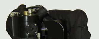
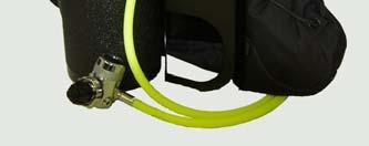
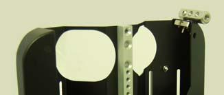

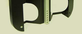
79 DURABLE RELIABLE 1 MSL Jetsam/Explorer R.2
80 READ THIS MANUAL & THE CLASSIC MANUAL!!!! KISS EXPLORER DIVERS MUST READ BOTH THE EXPLORER MANUAL AND THE CLASSIC MANUAL. THEY GO TOGETHER. THE EXPLORER MANUAL ONLY COVERS THE FEATURES WHICH DIRECTLY RELATE TO THE EXPLORER. IN ORDER TO FULLY UNDERSTAND YOUR NEW REBREATHER, THE COMPONENTS, HOW THEY WORK, HOW TO HANDLE AND TREAT THEM, YOU MUST READ THE MANUAL IN FULL, FOR YOUR REBREATHER. SPORT KISS OWNERS SHOULD READ THE SPORT KISS MANUAL. CLASSIC KISS OWNERS SHOULD READ THE CLASSIC KISS MANUAL. EXPLORER OWNERS SHOULD READ BOTH THE EXPLORER AND CLASSIC MANUALS. CLASSIC OWNERS WHO HAVE UPGRADED TO SOME OF THE EXPLORER COMPONENTS SHOULD READ BOTH THE CLASSIC AND EXPLOR ER MANUALS. THIS SHOULD BE DONE PRIOR TO DIVING OR SERVICING THIS UNIT!!! SPECIAL ATTEN TION SHOULD BE PAID TO ALL NOTES &/OR WARNINGS; THEY MUST BE READ AND UN DERSTOOD!!!! FAILURE TO DO SO, MAY CAUSE SERIOUS INJURY OR DEATH!!!! THE KISS EXPLORER GIVES DIVERS OPTIONS ON HOW TO RIG THEIR UNIT. THIS MANU AL IN NO WAY REPLACES THE TRAINING REQUIRED FOR EXPLORATION DIVING &/OR TECHNICAL DIVING. PROPER TRAINING IS EXTREMELY IMPORTANT AS IS GATHERING PROPER EXPERIENCE PRIOR TO ATTEMPTING ADVANCED DIVING. YOU MUST BE A LEGAL ADULT IN THE AREA IN WHICH YOU LIVE IN ORDER TO PUR CHASE AND DIVE A KISS REBREATHER. As with all scuba diving equipment, your KISS rebreather components should be serviced annually by a trained technician. For those diving frequently, servicing may be required more o en. ALL INFORMATION IN THIS MANUAL IS SUBJECT TO CHANGE. PLEASE VISIT OUR WEBSITE, FOR UPDATED MANUALS. 2
81 THIS IS NOT A JOKE!! Par cipa on in rebreather diving can result in serious injury or death to you, the diver! The warning on the Classic KISS rebreather is not a joke. Before beginning your dive, you must consider the risks involved. The Classic KISS consists of many parts. All of these components will eventually fail. Careful maintenance, assembly, and tes ng will not prevent this from happening. At best, it will delay the failure. The Classic KISS is not automa c in any way. It requires constant monitoring, a complete awareness of the poten al problems likely to be encountered, and full knowledge of how to deal with whatever problems may occur. If you do not have adequate training, equipment, physical condi oning, and a proper mindset, do not get in the water. The diver, YOU, has the final responsibility for his or her own safety and ac ons while using this rebreather. All components of the Classic KISS must be in good working order and be properly assembled and tested to reduce the risk of failure. Regardless of the training and experience of the diver and the reliability of the rebreather the risk of serious injury and/or death can never be reduced to zero. This manual is not a complete text on the maintenance and opera on of the Classic KISS Explorer. The diver must complete a proper training course covering the maintenance, tes ng and opera on of the rebreather before diving this equipment. The rebreather can malfunc on while diving even when properly assembled and having passed all pre dive tests. Only carrying adequate bailout gas and having the training and skills necessary to u lize the bailout system can reduce, but never eliminate, the risk of equipment failure. 3 MSL Jetsam/Explorer R.2
82 CLASSIC KISS, EXPLORER THE ORIGINAL KISS REBREATHER, MECHANICALLY CON TROLLED, MANUALLY ASSISTED, IS NOW AVAILABLE IN AN EN HANCED PACKAGE! The Classic KISS rebreather has always been known to be DURABLE, RELIABLE and FLEX IBLE. With the Explorer, we take the original version and add the features that divers have been asking for: a unit be er equipped for explora on but which does not compromise on quality and keeps to the KISS philosophy. Also desired by divers is the ability to modify the rigging of the unit to be er work with the environment at hand, the planned dive, or gear available at the des na on. And, they would like to be able to do this quickly and easily! The Explorer does all this; it can be rigged several different ways! TABLE OF CONTENTS EXPLORER parts list Page 5 Set up op ons and components Page 7 Counterlung case and KISS wing Page 9 Harness Page 12 Cylinder straps Page 13 Off board accessory Page 14 Le side gas addi on valve & Miflex hoses Page 16 Le side gas addi on valve trouble shoo ng Page 18 EXPLORER with on board oxygen only Page 19 EXPLORER with on board oxygen & diluent Page 20 EXPLORER for travel Page manifold to diluent first stage hose Page 23 Add valve quick connect system Page 24 4
83 EXPLORER PARTS LIST Congratula ons on purchasing the KISS Explorer. This is a unit for divers who want op ons when configuring their rebreather; rigging can be personalized to suit the divers personal style or to suit specific diving requirements. It is up to you, the diver to ensure that the system is rigged properly for the diving that you are planning on execu ng and also to ensure that you are properly trained and have the appropriate gear and bail out gas. 1 Explorer counterlung case with detachable front plate and webbing harness. Also included are 2 a achment screws for securing front plate to case; screw sets for securing the cover plate, if the KISS wing is not used; detachable manifold; spine; detachable tank rails Custom KISS wing. Includes over pressure valve as well as infla on hose and inflator 1 scrubber head with all required parts (CL a achments and rings, towers, 2 elbows (le side with appropriate tube), exhaust valve, draw nut) 1 scrubber head hat 2 counterlungs: includes a 2 liter and a 4 liter unless otherwise specified no charge for different combina on 1 diluent first stage with, OPV, and 2 swivel elbows 1 oxygen first stage with delrin plug, OPV, and swivel elbow 1 right side oxygen manual add valve with constant flow orifice, filter and 2 yellow Miflex hoses 1 le side gas addi on valve; choose either no flow oxygen valve or no flow diluent valve.. With filter and 2 black Miflex hoses 1 ADV assembly: cover, diaphragm, valve bolt, valve stem, LP swivel elbow 1 LP diluent hose with hose adapter (ADV swivel to manifold) 1 LP diluent hose with hose adapter (Manifold to diluent first stage) 1 Scrubber canister with protec ve coa ng. Also includes the base & inner tube, which is packed with: 4 small lined hose clamps to a ach quick connect system to loop hoses 2 O ring sets One is a spare 1 nut driver 1 KISS tool for draw nut 1 back plate a achment kit: 2 1 inch hex bolts, 2 1 1/2 inch hex bolts, 2 fender washers, 2 lock washers 1 counterlung ring, spare 8 SS ballast rings 2 scrubber head plugs. For use if the le side elbow is removed 1 bailout mouthpiece with LP hose 2 sets (four straps) webbing for on board cylinders 2 loop hoses: 22 included unless otherwise specified no charge to replace with 17 hoses 1 complete off board accessory kit (rebreather side and cylinder side) 4 quick connect hose stubs for loop hoses 1 CD Manuals 5 MSL Jetsam/Explorer R.2
84 DISPLAY OPTIONS, IF ORDERED: Jetsam triple wrist display with a achment plate, 2 wrist straps and jewelers screw driver set Jetsam dual wrist display with VR3 cable, 2 wrist straps and jewelers screw driver set (cable will read one sensor) VR pendent display with dual fischer a achment plate Dual fischer a achment plate only No display Op onal Shearwater HUD a aches to dual fischer plate NOT INCLUDED: AI PSR MD sensors (3), pressure gauges (2). Sensor warranty periods start from the moment they are shipping from the Teledyne warehouse. As such, it is best that they are ordered directly from the distributor or a dealer so that you get the freshest sensors possible. This way you know they have not been si ng on our shelf for some me. Most divers have pressure gauges which can be used. Addi onal LP and HP swivels. EXTRAS: We are happy to supply you with addi onal LP swivel elbows and off board gas accessories. HP swivel elbows are also available. Quick connects for the right side oxygen manual add valve and the le side gas addi on valve. These quick connect sets are for those who wish to dive their Explorer with no on board gas, also known as the Travel Explorer. A quick connect is required as this system allows divers to put their rebreathers on separately from the cylinders. Large side mount cylinders can be a ached while in the water. Please see page 21 for a full descrip on of this method of diving. 6
85 SET UP OPTIONS & COMPONENTS This sec on of the manual discusses the various op ons for rigging the KISS Explorer. Explorer owners should read carefully the sec ons below to determine which rigging methods are appealing. There are some components which are not included in the Explorer package, which are required for some of these methods. We chose not to include all the parts for every rigging style, as not every diver will require them. This helps to keep the cost of the unit down, and divers can then purchase what they need. Once you determine which style suits you, turn to the appropriate sec on in the manual for further explana on of that rigging system. CYLINDER RIGGING OPTIONS 1. ON BOARD CYLINDERS: Standard, diluent and oxygen; with addi onal diluent/bailout as side mount. With this system, divers can choose any mix they like for the le side cylinder. With this system, divers would plumb their side mount cylinders into the Explorer using the off board accessory. Extra full off board kits or cylinder side whips can be purchased. Divers need to decide which le side gas addi on valve they would like to use. They can choose either the noflow oxygen valve or the no flow diluent valve. See below for full add valve descrip ons. The right side oxygen manual add valve with flow is standard. 2. ON BOARD CYLINDERS: Oxygen only; with diluent/bailout as side mount. With this system, divers would plumb their side mount cylinders into the Explorer using the off board accessory. One off board accessory kit (rebreather side and cylinder side) is included with the Explorer. It a aches to the Explorer through the manifold. The Explorer can easily be rigged with 2 full off board kits, if desired. This way, 2 side mount cylinders can be plumbed into the rebreather, and no disconnec ng of the off board is necessary. Or just 1 off board rebreather side whip can be used. With this set up, the quick disconnect would be u lized when switching to other cylinders. Divers can purchase extra cylinder side whips, if desired. For those that wish to dive with 2 on board oxygen cylinders, the le side gas addi on valve should be the oxygen valve with no flow. Please see the gas addi on valve sec on below for a full descrip on of this valve. The diluent add valve should not be used; the flow is too high!! The right side oxygen manual add valve with flow is standard. 3. OFF BOARD CYLINDERS ONLY: diluent and oxygen as side mount only. This method, also known as the Travel Explorer, does not use on board cylinders. Cylinders of any size can be used, as they are side mounted. With this rigging method, divers will have their diluent cylinder plumbed to the off board accessory and they will also have use of a le side gas addi on valve, if you choose to dive with it. Divers will need to decide which le side gas addi on valve they would like to use. They can choose either the no flow oxygen valve or the no flow diluent valve. See below for full add valve descrip ons. The right side oxygen manual add valve with flow, is standard. it does not require an off board accessory. GAS ADDITION VALVES 1. Right side, oxygen manual add valve with flow. This is standard and is included in all Explorer packages. This is the original manual add valve which is used on all KISS rebreathers. 2. Le side gas addi on valve, oxygen no flow. This valve is the same as the right side valve, but it DOES NOT HAVE AN ORIFICE! Instead it is plugged. Gas will only go into the rebreather from this valve if the bu on is pushed. 7 MSL Jetsam/Explorer R.2
 to do a quick diluent flush. 3. Le side gas addi on valve, diluent no flow.")
86 This valve is shipped oxygen clean. It can be used with either oxygen or any other type of gas. Divers should be aware that if they use this valve for diluent, it will NOT have enough flow (when the bu on is pushed) to do a quick diluent flush. 3. Le side gas addi on valve, diluent no flow. This valve has been modified from the original O2 manual add valve; the flow has been increased. Also, IT DOES NOT HAVE AN ORIFICE; it is plugged. This means that the only way this valve will deliver gas into the rebreather, is by pushing the bu on. As this valve has a higher flow, it should NOT be used with oxygen. GAS ADDITION VALVES WITH QUICK DISCONNECT FITTINGS (the quick disconnect fi ngs are an op onal product and not included with the EXPLORER package.) 1. QD fi ngs not a ached to the manual gas addi on valves: Unless the KISS Explorer is set up for the no onboard cylinder/travel version, these fi ngs are not required. While they can be used, divers should remember that the more fi ngs on the rebreather, the more failure points it has. 2. QD fi ngs a ached to the manual gas addi on valves: The QD fi ngs enable the diver to dive without onboard cylinders, using side mounted cylinders only. (the QD fi ngs must be ordered extra). With this rigging method, the rebreather first stages are used as the side mount first stages. These QD fi ngs are required if the diver wishes to use heavy cylinders which must be a ached in the water. The QD allows the add valve hose system to split, making this possible. This method would require the diver to a ach the bailout regulators to these first stages. Please see page 21 and page 24 for full details on diving this rig. GAS ADDITION VALVE ROUTING The Explorer ships with the add valves si ng over the divers shoulders. You may choose to route the valve so that the hoses wrap around your waist with the valve clipped on the lower part of your harness. To do this, you will need to turn the scrubber head elbow so that it turns down. Then a ach the longer Miflex hose to the elbow, and the shorter hose to the first stage. Basically, you are switching them from how they are shipped. Remember, the hose from the first stage should be a ached to the filter on the add valve. LEFT SIDE GAS ADDITON VALVE It s worth no ng that this valve does not need to be used on every dive. It is included in the Explorer kit as it is a feature that some divers require on their technical dives. If you find that it isn t a feature that you need at this point in your diving, it can be removed. The easiest way to do this is to remove the miflex hose from the elbow and use a standard LP first stage port plug to close the elbow. This way, it doesn t need to be removed and the add valve can easily be reinstalled when required. 8

87 COUNTERLUNG CASE & KISS WING The new Explorer counterlung case ships with the front plate a ached, and the wing NOT a ached. You will no ce that without the wing a ached, the plate is secured in the four outer corners with screw sets. Also, the top centre screw has a spacer in between the spine and the back of the front plate. This spacer and the 4 screw sets are NOT required when diving with the KISS wing. As the KISS wing sits between the front plate and back box, the plate will sit snugly and their will be no gapping in between the parts. The corner screw sets are used to take up the gapping if the case is dived without the wing. Those diving without the wing, may choose not to use the corner screw sets, but add a third spine screw at the bo om. Or as your wing a aches with a screw in this area anyway, it would also be sufficient. The choice is really the divers; the screw sets are included for those who wish to use them. Please see the next page for more informa on on the corner screw sets. The spacer (black plas c washer) which is located in between the spine and the plate, at the top is also op onal. It is there to remind you to NOT over ghten that top (or bo om screw, if used) all the way down, if the KISS wing is not used. If you choose to not use this washer, or if you lose it, just don t ghten the screw down all the way. Leave a small gap. If the screw is ghtened down all the way, it will put stress on the case. The KISS Explorer counterlung case a aches to the scrubber head in the same manner of the Classic KISS; with two, 2 inch flat head screws. For those upgrading older Classic KISS units, the exis ng screws can be used. If for some reason, new screws are required to complete the upgrade, they should be ordered with the case. When swapping cases, do not forget to insert the spacer between the head and the case. New units ship with everything in place. A er a aching the back part of the counterlung case to the scrubber head, the various fi ngs can be rea ached to the head. Again, those buying a new Explorer will find everything a ached. At this point, the counterlungs can be a ached to the unit. Please see the Classic KISS manual for proper CL inser on instruc ons. The next step would be to a ach the custom KISS wing and front plate. The wing is situated between the back part of the counterlung case and the front plate, This posi oning keeps the Explorer very ght to the divers back and provides a low profile. As this wing was designed for the KISS Explorer, it best provides li where required and has excellent trim. It has a 360 degree donut style bladder assembly and maximum li is approximately 40 lb. Tightening the bungees will lower the profile and reduce the li. To a ach the KISS wing, you will need the 4 barrel nuts which are part of the package. Posi on the wing so that the inflator and the dump valve are on the right side. The top of the wing is narrower than the bo om. The top also has a tab in the middle of the top por on. See photo to the right. This side is also the side which should be facing you when the wing is a ached. 9 MSL Jetsam/Explorer R.2


88 With the wing properly posi oned, it can now be a ached using the 4 barrel nuts. The wing a aches to the four corners of the counterlung case. On the back side of the wing, there are loops in each corner which have a large stainless steel grommet. Push the female piece through the loop so that the open side is facing the case. Then push the male piece through the hole in the corner of the case, so that the threaded end is facing the wing. Secure them, finger ght. The barrel nuts are meant to be hand ghtened only. Do this for each of the four corners. To secure the barrel nut by the manifold mount, first push the male piece through the hole in the case, then line it up with its ma ng piece. When the wing is a ached at all four corners, you will no ce that it seems loose. This is normal. When the top plate is fi ed, everything will be posi oned properly and will be snug. Posi on the top plate as shown in the right hand photo, with the crotch strap slot at the bo om. The photo at the right shows the case assembled without the wing. Arrows are poin ng to the 2 securing screws and the crotch strap slot at the bo om of the case. When using the wing, the 4 a achment screws for the outer corners of the top plate, are not used. Slide the plate under the top flap of the wing first. Then pull the bo om flap over the bo om of the plate. Line up the plate with the spine and a ach the 2 pan head screws. It is best to ghten the plate while the unit is laying down. With one hand, apply pressure to the plate pushing it into posi on, and ghten the screws with the other. Ensure that it is properly secured. The screws for this applica on are 5/16 18 x 5/8. The wing has both an inflator hose and a dump valve. Both are on the le side (when wearing the unit). 10


 screw should not be ghtened all the way, if the spacer is not used.")

89 The Explorer counterlung case can be dived without the KISS wing. To do this 4 screws/4 washers/4 nuts which are included with the kit, can be used. As men oned on the previous page, this is up to you, as a third spine screw at the bo om will also help secure the plate. You may feel that your wing/harness a achment screws will anchor the plate properly. The spine screws for this method are s ll the 5/16 18 x 5/8. If you are planning on diving with the corner screw sets, be certain to a ach the spine screws first. Otherwise, they will be difficult to line up. The four outer corners will require each, a screw, washer and nut. The washer acts as a spacer to take up room where the wing would normally sit. To assemble, place the screw through the plate, the washer between the plate and the back counterlung case, and the nut on the inside of the counterlung case. Secure. See the photos below. The corner screws are 5/16 18 x 5/8, using a 5/16 hex nut. As men oned on the previous page, if the wing is not used, the top (and bo om, if used) screw should not be ghtened all the way, if the spacer is not used. To a ach the cord, thread it through the top, back grommet with the knot on the outside. See photo to the far right, top red arrow. Thread the cord through the grommets on the edge of the wing, and then through the webbing on the front of the wing. Con nue threading the cord, alterna ng from one side to the other, and u lizing the grommets on the edge of the wing.. See photos above. Once the cord has been threaded, pull it through the last grommet at the bo om back of the wing, and secure it with a knot. Any le over cord, can be threaded through the slots to secure it. 11 MSL Jetsam/Explorer R.2
, adjustable crotch strap with scooter ring and D ring/slide, 11 feet of")


90 KISS WING HARNESS The KISS Explorer front plate is designed to work as a back plate; slots have been cut for a standard webbing harness. The harness is shipped with a SS buckle, 2 D rings/slides per shoulder strap, 1 D ring/slide per waist strap (1 on each hip), adjustable crotch strap with scooter ring and D ring/slide, 11 feet of webbing, and 4 webbing protectors. Should any more rings or accessories be desired, they can easily be added. While the Explorer ships with our webbing harness, you may decide to thread your own harness into the Explorer s front plate, or alterna vely, to a ach a standard harness system using the threaded holes on the plate. (similar to the Classic KISS). The bolts for this applica on are included. THREADING THE HARNESS: 1. Thread the webbing through the shoulder strap slots. Posi on the webbing so that the grommet is posi oned to the right or le of the center. If the grommet is in the center, you will not be able to ghten the top screw properly. As there is plenty of webbing this shouldn t be an issue. See the photo to the right. Before you slide the webbing through the slots, push two of the webbing protectors over the webbing. The protectors should sit so that they cover the webbing which goes through the slots. This will help prevent wear & tear on the harness. 2. Posi on 2 D rings/slides on each shoulder. See the top photo for posi oning. Note that the top ring should sit fairly high; approximately 3 to 5 from the top of the plate. Remember, the rebreather needs to sit as high on your back as possible for the best work of breathing. THIS IS VERY IMPORTANT!! 3. Next, thread the end of the webbing through the waist slot. Push the end through the front of the plate towards the back, and then forward through the next slot. See photo to the right. Repeat this step with the 2nd piece. Again, two of the webbing protectors should be used to protect the harness. 4. Posi on 1 D ring/slide on each waist strap. See top photo. 5. Install the crotch strap. Major adjustments should be done on the back part of the webbing. Minor adjustments should be done on the front part of the webbing. The front loop will be threaded over the waist webbing on the right side. 6. A ach the waist buckle to the webbing on the right side. For those that have never adjusted a webbing harness, it will take a few a empts in order to achieve the desired fit and to ensure that the rebreather si ng high enough. Be prepared and give yourself plenty of me. is Worth no ng is that the waist strap is probably best adjusted so that it sits over your hips; lower on your body, rather then higher. Keeping the waist strap low, and the crotch strap snug, will ensure that the harness sits securely and does not shi. Adjus ng your harness this way, will also help keep the rebreather higher up on your back. The Explorer plate has several addi onal holes drilled into it. They are there for a aching various accessories such as bu plates or side mount bungee for tank valves. 12


91 CYLINDER STRAPS The KISS Explorer is shipped with 2 sets (4 straps) of the webbing straps. They are a standard feature for the Explorer. These straps can be locked under the tank mount brackets on the case. Loosen the tank mount brackets, and instead of sliding the straps through the slots on the case, slide them under the tank mount bracket instead. Posi on the strap so that the buckle is located where you want it and then ghten the tank mount bracket again. This will keep the straps from sliding around while you a ach your cylinders. 13 MSL Jetsam/Explorer R.2
92 OFF BOARD ACCESSORY The KISS Explorer package includes one full set of the off board accessory. This accessory is used to plumb the side mount gas into the KISS Explorer through the manifold. The kit includes the rebreather side whip and the side mount cylinder side kit. Some divers choose to dive with two complete off board accessories. Using two sets means that if two side mount cylinders are hooked up, the diver does not need to detach the quick connects from one cylinder to another. This version, while prac cal does add extra O rings to the rig. Alterna vely, the diver can choose to purchase only addi onal cylinder side whips. If the diver has this whip on each side mount cylinder, then in order to bring the gas into the rebreather loop, the diver must connect his rebreather side whip to that par cular cylinder. This version cuts down on the number of O rings on the rig and also is cleaner. The off board accessory rebreather side includes: 1 swivel elbow, 1 30inch LP hose, 1 shut off valve, 1 check valve with quick disconnect male. The off board accessory cylinder side includes: 1 swivel elbow, 1 6inch LP hose, 1 quick disconnect female. The shut off valve is open when it is pushed up, following the direc on of the arrow or pushing it towards the LP hose. It is closed when it is pushed down or away from the LP hose. The valve has been designed this way so the diver must make a conscious decision to open the valve. When doing your posi ve & nega ve pressure tests, remember to close this valve or your tests will fail!! Prior to connec ng the rebreather side whip to the off board cylinder, you must open the rebreathers on board diluent cylinder to pressurize the whip. Ensure that the shut off valve is open, with the arrow pushed up towards diver. This confirms that the one way check valve has seated. No gas should exit the off board whip. The check valve has three internal parts; a spring, a poppet, and an O ring. This process insures the poppet has seated in the O ring. Make this part of your pre dive check list. With this system, the diver can have the off board cylinders open through out the dive. Even if the quick disconnect is not connected. The check valve in the manifold whip will prevent any water from entering the system. 14
93 AS WITH ANY NEW DIVING EQUIPMENT, USING THIS ACCESSORY WILL REQUIRE THE DIVER TO LEARN NEW SKILLS AND CREATE NEW MUSCLE MEMORY. WITH ANY TYPE OF DIVING, REBEATHER OR OPEN CIRCUIT, THERE IS RISK. WHEN USING NEW EQUIPMENT SUCH AS THE OFF BOARD ACCESSORY ON A KISS REBREATHER, THE DIVER MUST ACCEPT THIS RISK AND THAT THE ABOVE MENTIONED NEW SKILLS WILL NEED TO BE LEARNED. FAILURE TO LEARN THE PROPER USE OF THE OFF BOARD ACCES SORY CAN CAUSE THE DIVER SERIOUS INJURY OR DEATH. 15 MSL Jetsam/Explorer R.2
94 LEFT SIDE GAS ADDITION VALVE & MIFLEX HOSES The KISS Explorer ships standard with a le side gas addi on valve. Either an oxygen valve or a diluent valve can be used. One valve is included with the Explorer. Addi onal valves can be purchased, if desired. This means that we now have 3 gas addi onal valves. 1. The original oxygen manual add valve which is located on the right side of the rebreather. This valve delivers oxygen in two ways. First through the constant flow orifice and second when the bu on is pushed. 2. Le side diluent gas addi on valve: this valve delivers gas only when the bu on is pushed. It does NOT have an orifice; it is plugged. The flow for this valve, when the bu on is pushed, is higher than the oxygen valves. While this valve is oxygen clean, it should not be used for oxygen mixtures as the flow is high. 3. Le side oxygen add valve: this valve delivers gas only when the bu on is pushed. It does NOT have an orifice; it is plugged. This valve has a similar flow as the right side valve, when the bu on is pushed. This valve can be used for any gas mixture. In order to determine which valve is which, we have engraved the larger fi ng on the valves. The fi ng which is secured into the housing on the bu on side, will be engraved. Also, we have labelled the filter on each valve assembly. *WARNING: If you remove your valve from the unit, keep spare valves, or keep different valves in your kit, be certain that you know what they are for! Read the inscrip ons and use the correct valve for your planned dive. As the le side valve does not have an orifice, the le side first stage is not modified. It is a standard first stage. This means that the le side valve will add gas at any depth. This is especially handy for those divers who prefer to run their right side valve at a lower flow, and are unable to add oxygen at depth. For those upgrading older Classic KISS units to a le side valve, note that both an elbow and tube are required. When installing the elbow and tube on the le side, the outer brass plug and inner stainless steal plug must be removed. Once removed, put them someplace safe; if you ever want to remove the elbow assembly, then BOTH of these plugs must be reinserted. In the event that you don't want to use the elbow, it may be easier to remove the hoses, and plug the elbow using a standard 3/8 first stage plug. *WARNING: IF THE 2 PLUGS ARE REMOVED, IT IS IMPORTANT THAT THE TUBE IS USED WITH THE ELBOW. THIS IS CRITICAL FOR PROPER GAS ROUTING. ALSO, IF THE ELBOW ASSEMBLY IS REMOVED, IT IS ALSO CRITICAL THAT BOTH PLUGS ARE RE INSTALLED! FAILURE TO DO SO WILL ALSO CAUSE INCORRECT GAS ROUTING. EITHER OF THESE PROBLEMS, COULD CAUSE INJURY OR DEATH! 16
95 Those that are installing the elbow themselves, should first apply Teflon tape to the threads. While this is not a pressure fi ng and tape really isn t required, it will help protect the threads. When a aching the elbow, ensure that it is not cross threaded. Also, do not over ghten. It is not required. Four to five turns is enough. The best tool to ghten the elbow is a 5/8 wrench. Use it to cup the bo om of the elbow to help turn it into posi on. You should only need the wrench on the last turn. The first few turns can be done by hand. *NOTE: The right and le side elbows, which a ach to the rebreather head, are NPT or pipe thread. This is a tapered thread, NOT a straight thread. If you screw a fi ng with a straight thread, such as a swivel elbow, into this port it will damage the rebreather head! If this happens, it is NOT repairable. Prior to modifying your rebreather, please be certain that you understand what fi ngs are required. *NOTE: See the Classic KISS manual for instruc ons on disassembling and servicing the gas addi on valves. *NOTE: Remember, when a aching the gas addi on valve to the hoses or other fi ngs, always put one wrench on the fi ng which a aches to the plas c valve. Use this wrench to ensure that this fi ng does not spin while you are either a aching or removing the valve from other fi ngs or hoses. If you need to remove or a ach any fi ngs which go directly into the plas c, be careful to not over ghten. Use only two fingers on the wrench! The hoses for the le side gas addi on valve are both Miflex hoses which are rated for oxygen use. As the Explorer has two similar gas addi on valves, it is important to differen ate between them. Therefore, the right side valve hoses which have always been for pure oxygen, remain a bright yellow colour. The new hoses will be black. WARNING FOR RIGHT & LEFT SIDE ADD VALVES! The oxygen injector, is a convenience. It is not a controller in any way. The only device regula ng the oxygen par al pressure is your brain. The automa c oxygen add does not reduce the need to monitor the three par al pressure displays. It only reduces the number of mes you have to press the oxygen add bu on. As with any rebreather, the displays should be checked constantly during the dive. The oxygen regulator can fail and stop delivering 02 or it can fail and increase the flow dras cally. The orifice can become plugged and stop delivering oxygen. The add valve O rings can fail and increase the amount of 02 being added to the breathing loop. Any of these things can kill you but any of these problems can be overcome if you are aware of the condi ons in the breathing loop. KNOW YOUR PO2 AT ALL TIMES! 17 MSL Jetsam/Explorer R.2
96 Le Side Gas Addi on Valve Troubleshoo ng If the gas addi on rate is lower than it should be, the following has happened: The filter has become clogged and should be replaced. If the gas addi on rate is higher than it should be, then one of the following things has happened: The plug has become loose where it screws onto the valve. The valve o ring is worn or damaged. The spring is broken or weakened and is not holding the valve closed. The regulator should be serviced regularly and maintained in an oxygen clean condi on. *WARNING: It is very important that this valve is in good working order, with good O rings. Ensure that you rinse your gear a er diving in salt water, and if you flood your rebreather, and you think water has go en into the valve, service it!! If you pay a en on to how o en you usually add oxygen to your rebreather during a typical dive, it will be easier for you to no ce a problem. *NOTE: The Miflex hoses are rated for oxygen use. As they have standard regulator hose fi ngs, they can be replaced with other rubber LP hoses. If you do so, please ensure that the hoses you use are rated for oxygen use! Also, all low pressure hoses on the KISS Explorer should be inspected periodically to ensure that they are not damaged and in good working order. This includes the oxygen hoses, diluent hoses, mouthpiece 2nd stage regulator hose and ADV hose. 18
97 EXPLORER WITH ON BOARD OXYGEN ONLY This system is for divers who wish to have redundant oxygen. These divers feel that having only one oxygen cylinder for a technical dive, is the weak link of the system. With this configura on, the divers diluent gas is the side mount/bailout gas. *WARNING: As always, all dives should be conducted with the appropriate gear, training and mind set. If any one of these is lacking, death could result! With this system, divers would plumb their side mount cylinders into the Explorer using the off board accessory. With the side mount cylinders a ached to the loop via the off board accessory, gas can be added to the loop in two ways. First by using the ADV and second by using the mouthpiece. Also, open circuit gas can be breathed via the rebreather mouthpiece. As the side mount cylinder is also the bail out cylinder, divers should have a bail out regulator a ached to these cylinders. *WARNING: Diving the bail out/side mount cylinders WITHOUT second stages should not be done. If the rebreather mouthpiece for any reason fails, then the bail out gas would not be accessible. Also, divers should ensure that they plan their dives appropriately and take in considera on their gear configura on as well as their buddies gear configura on. Ensure that all divers are properly trained for the planned dives and that they understand each others gear. Failure to do so, may result in injury or death! *WARNING: If you are going to dive this system, with two on board oxygen cylinders, you MUST remove the 21 LP hose and adapter, which runs from the manifold to the diluent first stage. If you do not do this, you will be adding both pure oxygen from the le on board cylinder and also diluent from your side mount cylinder through the ADV!! The ADV should ONLY add the gas from the side mount diluent cylinder!! If oxygen is in the le side cylinder, it must ONLY be added to the rebreather using the le oxygen gas addi on valve. Diving in this manner presents challenges and therefore it is only for those with advanced diving experience and adequate training!!! If divers are using large side mount cylinders that are a ached to the system in the water, they need to understand that the ADV will not work un l the side mount cylinder is a ached, using the offboard accessory. SEE PAGE 13. Having two on board oxygen cylinders means that divers need to pay special a en on to their PPO2 s!! The PPO2 will creep up if no diluent is being added! The ADV and the mouthpiece/ open circuit will not work un l the off board accessory is connected! The KISS Explorer was meant to be used with the off board accessory in place. Diving without it means that not all the components will work!! If you are planning on diving this configura on, ensure that you have the proper training and skills. This is not meant for beginner rebreather divers! It is for experience rebreather divers with proper training and experience! Those that wish to dive this configura on should choose the le side oxygen gas addi on valve with no flow. It is oxygen clean. The diluent valve should not be used as the flow is high for oxygen! This valve is similar to the right side oxygen manual add valve, but it DOES NOT HAVE AN ORIFICE. It is plugged. The only way the oxygen goes into the breathing loop is by pushing the bu on. This is a mul purpose valve as it can be used with other gas mixtures. 19 MSL Jetsam/Explorer R.2

98 EXPLORER WITH ON BOARD OXYGEN AND DILUENT This system is for divers who wish to have both on board diluent and side mount diluent/bail out gas. These divers prefer to dive the rebreather in a similar manner as the Classic KISS, with a breathable on board gas in the diluent cylinder. With this configura on, the divers on board gas and side mount/bail out gas can be any mixture which is appropriate for the dive. *WARNING: As always, all dives should be conducted with the appropriate gear, training and mind set. If any one of these is lacking, death could result! With this system, divers would plumb their side mount cylinders into the Explorer using the off board accessory. With the side mount cylinders a ached to the loop via the off board accessory, gas can be added to the loop in two ways. First by using the ADV and second by using the mouthpiece. Also, open circuit gas can be breathed via the rebreather mouthpiece. As the side mount cylinder is also the bail out cylinder, divers should have a bail out regulator a ached to these cylinders. *WARNING: Diving the bail out/side mount cylinders WITHOUT second stages should not be done. If the rebreather mouthpiece for any reason fails, then the bail out gas would not be accessible. Also, divers should ensure that they plan their dives appropriately and take into considera on their gear configura on as well as their buddies gear configura on. Ensure that all divers are properly trained for the planned dives and that they understand each others gear. Failure to do so, may result in injury or death! Those that wish to dive this configura on may choose either the no flow oxygen valve or the no flow diluent valve. The diluent valve, while it is oxygen clean, has a higher flow and therefore should not be used with oxygen mixtures. This valve is plugged; it has NO orifice. The gas enters the loop when the bu on is pushed. The diluent valve has a higher flow so that loop flushes may be conducted using this valve. Of course, diluent flushes can s ll be done using the mouthpiece/adv as with the Classic KISS. The oxygen valve can also be used, but divers should remember that when the bu on is pressed, the gas enters the loop much slower. This means that it shouldn t be used for a diluent flush as it will take too long. If this valve is used, do the diluent flush using the Classic KISS method of mouthpiece and ADV. 20
99 EXPLORER FOR TRAVEL This system is for divers who DO NOT WISH to have on board cylinders; they wish to use side mount cylinders only. Divers who prefer this configura on are usually explorers who require their gear to be as light as possible for transport to the diving loca on, or only have large cylinders available. Travellers also like this configura on. The simple changes for this configura on convert KISS Explorer into a light weight travel unit. It is different only due to it using off board cylinders only. This configura on allows divers to rent cylinders at their des na on. As the cylinders are side mounted, they can be any size; 30, 40, 60, 80 cubic feet. The KISS Explorer travel rebreather u lizes the same first stages and gas addi on hose system. However, an addi onal quick connect system is required with the exis ng hose system. These are not included in the Explorer kit and must be purchased extra. See page 24 for installa on instruc ons & further informa on on this system. This quick connect system is required for those that wish to put the cylinders on in the water. If smaller cylinders are being used, they can be rigged top side, and then the quick connect system is not required. It is recommended that the quick connect hose system only be used if the Explorer is rigged for this configura on. Otherwise O rings (failure points) are being added to the system, which serve no purpose. The le side diluent/bail out cylinder is a ached to the loop by both the off board accessory and also the le side gas addi on valve. The right side oxygen cylinder is a ached to the loop by the oxygen manual add valve. *WARNING: As always, all dives should be conducted with the appropriate gear, training and mind set. If any one of these is lacking, death could result! With this system, divers would plumb their le, side mount cylinder into the Explorer using the off board accessory. With the side mount cylinder a ached to the loop via the off board accessory, gas can be added to the loop in two ways. First by using the ADV and second by using the mouthpiece. Also, open circuit gas can be breathed via the rebreather mouthpiece also. As the side mount cylinder is also the bail out cylinder, divers should have a bail out regulator a ached to these cylinders. *WARNING: Diving the bail out/side mount cylinders with NO second stage should not be done. If the rebreather mouthpiece for any reason fails, then the bail out gas would not be accessible. Also, divers should ensure that they plan their dives appropriately and take into considera on their gear configura on as well as their buddies gear configura on. Ensure that all divers are properly trained for the planned dives and that they understand each others gear. Failure to do so, may result in injury or death! *WARNING: If divers are using large side mount cylinders, a aching to the system in the water, they need to understand that the ADV, open circuit mouthpiece, rebreather loop and both the gas addi on valves will not work un l the diver hooks up the cylinders and secure the quick connects. The unit was meant to dived with the off board accessory and both gas addi on valves in place. Diving without these parts means that not all the components will work!! Divers should be aware that these are advanced diving procedures and that experience and training are required to dive this configura on. 21 MSL Jetsam/Explorer R.2


100 Those that wish to dive this configura on may choose either the no flow oxygen valve or the no flow diluent valve. The diluent valve, while it is oxygen clean, has a high flow and therefore should not be used in an oxygen environment. These valves are plugged; they do not have an orifice. The gas enters the loop when the bu on is pushed. The diluent valve has a higher flow so that loop flushes may be conducted using this valve. Of course, diluent flushes can s ll be done using the mouthpiece/adv as with the Classic KISS. The oxygen valve can also be used, but divers should remember that when the bu on is pressed, the gas enters the loop much slower. This means that it shouldn t be used for a diluent flush as it will take too long. If this valve is used, do the diluent flush using the Classic KISS method of mouthpiece and ADV. 22


101 21 LP MANIFOLD TO DILUENT FIRST STAGE HOSE This hose is standard on the Classic KISS as it is required to bring the diluent on board gas through the rebreather using the ADV. It is a ached to the diluent first stage and then to the manifold. See the photo on the right for placement. *Warning: Some divers may feel that this hose is redundant and wish to remove it. These divers should be aware that if it is removed, the ADV and the open circuit mode of the mouthpiece will not work un l a cylinder is a ached to the rebreather via the off board accessory!!! This hose should not be used if the diver is using pure oxygen in the le side cylinder. The ADV system is not meant for high oxygen mixtures. 23 MSL Jetsam/Explorer R.2


102 ADD VALVE QUICK CONNECT SYSTEM We recommend that the quick connect system is a ached to the add valve, on the out flow side. This ensures that the small amount of water which sits in the front of the check valve, will get atomized into the low pressure hose. The amount of water is very slight, and it does get atomized. Even s ll, it should be a er the add valve and filter set up. What this means is that when the quick connect system is apart, the add valve will be a ached to the side mount cylinder. Care should be taken to secure the valve to the side of the cylinder with bungees and/or clips, to ensure that it does not get damaged. Treat it as you would a second stage regulator, with care and respect. When a aching the fi ngs to the add valve, remember to put one wrench on the add valve fi ng and one on the quick connect. Do not allow the fi ng, which is directly a ached to the valve, to spin. It could strip the threads of the housing. See page 17 for more informa on on this subject and wrench placement photos. When your Explorer is rigged for travel mode, you must s ll do a full posi ve and nega ve test. This must be done with the complete loop intact. This means that the first stages must be secured to the side mount cylinders, and the quick connects pushed together. This is the only way to ensure that the posi ve and nega ve tests pass. Don t forget to push the shut off valve closed, on the off board accessory. If you don t, it will leak and the test will fail. While the en re loop is together, take the me to pressurize the off board whip. Simply open up the off board cylinder, while the off board accessory is connected to it. This will pressurize the whip, and will confirm that the one way check valve has seated. Ensure that the shut off valve is open, while you do this. This should be done prior to entering the water. See the off board sec on for full details. 24


103 KISS REBREATHER, LLC. 1 (479) MSL Jetsam/Explorer R.2
104 HOLLIS BOV (Bail Out Valve) SPECIFICATIONS Torques Inlet Coupling 35 to 40 in lbs (4 4.5 N m) LP Hose 35 to 40 in lbs (4 4.5 N m) Intermediate Supply Pressure Preferred 138 psi (9.5 bar) Acceptable 137 to 139 psi ( bar) Opening Effort IP = 138 psi (9.5 bar) Recommended Setup Range (Octopus) 1.5 to 2.2 inches of Water TOOLS REQUIRED Standard Tools Inch Pounds Torque Wrench 1/4 Open End Wrench 3/4 Open End Wrench 11/16 Open End Wrench 1/8" Allen Key 3/32" Allen Key Flat Blade (narrow) Jeweler's Screwdriver Specialty Tools Tribolube 71 Christo Lube MCG 111 Intermediate Pressure Gauge O ring Tool Kit In line Adjustment Tool BOV SPOOL TROUBLESHOOTING Co on Swab (Q Tip) SYMPTOM POSSIBLE CAUSE TREATMENT Failed mushroom valve checks obstructed or damaged mushroom valves (26), valve holders (22, 23), or O rings (24, 25) clean/replace mushroom valves (26), valve holders (22, 23), and O rings (24, 25) Leaking gas out of Breathing Loop worn O rings (18, 24, 25, 29) replace O rings (18, 24, 25, 29) Rough spool (16) opera on dirty or damaged ma ng surfaces clean/lubricate/replace O rings (18, 29), housing (1), or spool (16) Water spool (16) 1. mouthpiece (27) or Ty Strap (28) damaged, loose, or missing 2. bad O rings (18, 24, 25, 29) 3. Leak in Breathing Loop 1. replace Ty Strap (9) and/or mouthpiece (27) 2. replace O rings (18, 24, 25, 29) 3. see the "Breathing Hoses and Counterlungs" chapter
: OC (Open Circuit Posi on) used for bail out off of the rebreather CC (Closed Circuit Posi on) OC BOV SPOOL DISASSEMBLY NOTE:")
 on the BOV (Fig. 2).")
. Figure 1 Figure 2 2. Slide the silicone hose clamp covers off of the Oe ker clamps. 3.")
. Figure 3 4. Unscrew the breathing hose nuts, and remove the BOV breathing hoses and adapters. 5.")
, gently hold it open.")
105 BOV MODES CC The BOV has two modes that are alternated by moving the lever (34) (Fig. 1): OC (Open Circuit Posi on) used for bail out off of the rebreather CC (Closed Circuit Posi on) OC BOV SPOOL DISASSEMBLY NOTE: O rings must be changed any me they show signs of decay or damage. 1. Using an 11/16" open end wrench, remove the LP hose end from the coupling (2) on the BOV (Fig. 2). NOTE: To avoid internal corrosion and damage, NEVER submerge the BOV assembly in liquid with the LP Hose removed from the COUPLING (2). Figure 1 Figure 2 2. Slide the silicone hose clamp covers off of the Oe ker clamps. 3. Using Oe ker style pliers, remove the Oe ker clamps that retain the BOV hose adapters into the inhala on and exhala on breathing hoses (Fig. 3). Figure 3 4. Unscrew the breathing hose nuts, and remove the BOV breathing hoses and adapters. 5. Pinch the hose adapter O rings to remove as shown (Fig. 4). Inspect the O rings and sea ng surfaces for deteriora on and damage. If found, discard. Figure 4 6. Peel back the exhala on mushroom valve (6), gently hold it open. Then using the rubberized end of a pencil, wooden dowel, or other blunt instrument, insert the tool through the exhala on valve holder (22), and gently push out the inhala on valve holder (23) assembly (Fig. 5). Figure 5
, and clean the O ring (24, 25) grooves (Fig. 6). Inspect the O rings (24, 25) for damage. If found, discard. 9.")
 for cracks and other damage, discard if found. Otherwise, wash, sani ze, and remove any debris from the valve holders (22, 23). 11.")
 to ensure that it is supple and free of any tears or corrosion. Discard if found. Figure 7 12.")
 and BOV HOUSING (1). Figure 8 13. Using your thumbs, gently press the spool (16) out of the BOV housing (16) (Fig. 9).")
106 NOTE: DO NOT push on the center of the INHALATION VALVE HOLDER (23). ONLY push on the outer edge. 7. Turn the BOV over and press out the exhala on valve holder (22) in the same fashion as in step Remove the valve holder O rings (24, 25), and clean the O ring (24, 25) grooves (Fig. 6). Inspect the O rings (24, 25) for damage. If found, discard. 9. The mushroom valves (26) may be removed by grasping them at the flange and pulling them straight out, snipping the retainer stem if necessary (Fig. 7). Discard. Figure Examine the valve holders (22, 23) for cracks and other damage, discard if found. Otherwise, wash, sani ze, and remove any debris from the valve holders (22, 23). 11. Snip the plas c ty strap (28) that holds the mouth piece (27), and remove the mouthpiece (27). Inspect the condi on of the mouthpiece (27) to ensure that it is supple and free of any tears or corrosion. Discard if found. Figure Using a 1/8" L shaped Allen key, remove the lever screw (33), lever (34), and O ring (35) by turning counterclockwise (Fig. 8). Inspect the O ring (35) for any signs of decay. Discard if found. NOTE: Be careful not to damage the sealing surface of the inner METAL SPOOL (16) and BOV HOUSING (1). Figure Using your thumbs, gently press the spool (16) out of the BOV housing (16) (Fig. 9). Figure Remove the four O rings (18, 24, 25, 29) from the grooves of the spool (16). Discard the schedule A O rings (18, 29). Inspect the other O rings (24, 25) for any signs of decay. Discard if found. 15. Inspect the spool (16), O rings (18, 24, 25, 29) channels, the lever O ring (35) moun ng face, and inside the BOV housing (1) for damage (nicks, gouges, etc.) that would prevent the O rings (18, 24, 25, 29, 35) from sealing properly. If damage is found, the damaged part must be replaced.
. NOTE: Using a syringe simplifies this task and reduces waste.")
. 3.")
 are aligned when installing the SPOOL (16). Figure 11 4.")
 in place, and start the lever screw (33) by hand clockwise.")
107 BOV SPOOL REASSEMBLY 1. Lubricate the O ring channels for the 3 spool O rings (18), in the metal spool (16) (Fig. 10). Then install the four O rings (18, 24, 25, 29). NOTE: Using a syringe simplifies this task and reduces waste. Lubrica ng the 3 spool O ring grooves directly also improves SPOOL (16) rota onal movement. Figure Lightly lubricate the internal walls of the BOV housing (1). 3. Being careful not to pinch any O rings, press the spool (16) into the BOV housing (1) (Fig. 11). NOTE: Ensure that the holes for the installa on of the LEVER (34) are aligned when installing the SPOOL (16). Figure Holding the lever screw (33) in one hand, place the O ring (35) in the groove as shown (Fig. 12). Figure Hold the lever (34) in place, and start the lever screw (33) by hand clockwise. Then con nue ghtening the lever screw (33) with a 5/32" L shaped Allen key (Fig. 13). DO NOT over ghten. Figure 13 NOTE: Be careful not to damage the sealing surface of the INNER SPOOL (16) and BOV HOUSING (1). NOTE: If replacing the MUSHROOM VALVES (26), ensure not to place damaging stress on the VALVE HOLDERS (22, 23).
, while twis ng, un l the retaining flange is completely inside the valve holders (22,")
.")
. 8.")

108 6. If removed, replace the mushroom valves (26) by gently pulling the retainer stem through the valve holders (22, 23), while twis ng, un l the retaining flange is completely inside the valve holders (22, 23) and properly seated (Fig. 14). DANGER: DO NOT put lubricant on the MUSHROOM VALVES (26). Figure Lightly lubricate and refit the valve holder O rings (24, 25). Then press the valve holders (22, 23) back into place (Fig. 15). Be careful not to pinch the O rings (24, 25). 8. Lightly lubricate and install the hose adapter O rings onto the hose adapters. Figure Slide the hose nuts and silicone sleeves over the ends of the breathing hoses. Then install the BOV hose adapters onto the breathing hose ends (Fig. 16). 10. Using Oe ker style pliers rea ach the Oe ker clamps (Fig. 17). Figure 16 Figure 17
 onto the BOV housing (1) with a new ty strap (28), posi oning the locking tab of the ty strap (28) towards the")


109 11. Slide the silicone hose clamp covers back into place (Fig. 18). Figure Secure the mouthpiece (27) onto the BOV housing (1) with a new ty strap (28), posi oning the locking tab of the ty strap (28) towards the breathing hose. 13. Using an 11/16" open end wrench, ghten the LP hose end to the coupling (2) clockwise onto the BOV housing (1) (Fig. 19). 14. Screw the hose nuts clockwise onto the BOV. 15. Install the HUD bracket and HUD to the exhala on hose nut. A ach an O ring to the underside of the HUD bracket to secure it. Figure 19 NOTE: To avoid damage, slide the HUD bracket over the hose nut from the side. WARNING: Check for leaks and proper opera on before use of the BOV. DANGERS: Ensure the mushroom valves are installed correctly with gas flow from diver's le (inhala on side) to diver's right (exhala on side) as shown by the arrow (Fig. 20). Figure 20
110 SECOND STAGE TROUBLESHOOTING SYMPTOM POSSIBLE CAUSE TREATMENT Free flow or leakage present. 1. Excessive lever (9) height. 2. Excessive intermediate pressure from first stage. 3. Lever (9) bent. 4. Damaged or worn poppet seat (5). 5. Damaged orifice (3). 6. Lock nut (11) overtightened onto shaft of poppet (6). 7. Poppet washer (8) bent or distorted. 8. Poppet spring (7) weakened, worn, or incorrect part. 9. Orifice (3) incorrectly adjusted. 1. Adjust orifice (3) and lock nut (11) to arrive at correct spring load tension and lever (9) height. Refer to Tuning section. 2. Refer to First Stage Trouble- shooting chart. 3. Replace with new. 4. Replace with new. 5. Replace with new. 6. Replace with new and readjust. Refer to Tuning section. 7. Replace Poppet washer (8), spacer (10), and lock nut (11) with new. 8. Replace with new. 9. Turn in clockwise to adjust. Refer to Tuning Excessive inhalation resistance. 1. Lock nut (11) overtightened onto poppet (6) shaft, causing excessive spring (7) tension. 2. Lock nut (11) insufficiently tightened onto poppet (6) Shaft, causing lever (9) slack. 3. Lever (9) bent. 4. Orifice (3) incorrectly adjusted. 5. Insufficient intermediate 1. Replace with new and readjust. Refer to Tuning section. 2. Tighten to correct spring load and lever (9) height. Refer to Tuning section. 3. Replace with new. 4. Adjust to correct contact. Refer to Tuning section. 5. Refer to First Stage Trouble- shooting chart. Rattle heard inside Second Stage. 1. Lever (9) slack present. 1. Tighten lock nut (11) onto POPPET (9) Shaft. Refer to Little or no air flow when Purge Button is depressed. 1. Lever (9) slack present. 2. Lever (9) bent. 3. Orifice (3) incorrectly adjusted. 1. Tighten lock nut (11) onto poppet (6) shaft. Refer to Tuning section. 2. Replace with new. 3. Adjust orifice (3) to correct contact. Refer to Tun-
111 SYMPTOM POSSIBLE CAUSE TREATMENT Water entering Second Stage. 1. Tear in mouthpiece (27). 1. Replace with new. 2. Exhaust valve (13) distorted or damaged. 2. Replace with new. 3. Replace with new. 3. Diaphragm (21) distorted or 4. Tighten until secure. damaged. 5. Replace with new. 4. Cover ring (30) not tight on 6. Tighten or install. housing (1). 5. Cracked or damaged housing (1). 6. Mouthpiece ty-strap (21) loose or missing.

 to ensure that it is supple and free of any tears or corrosion. Discard if found. 2.")
. Figure 21 3. Turning counterclockwise, remove the cover ring (30) (Fig. 21).")
112 SECOND STAGE DISASSEMBLY NOTE: Be sure to check and record the intermediate pressure prior to disassembling the Explorer BOV. Review the Troubleshoo ng sec on to be er understand which internal parts may need replacing, and to be er advise the customer of the service required. 1. Snip the plas c ty strap (21) that holds the mouthpiece (27), and remove the mouthpiece (27). Inspect the condi on of the mouthpiece (27) to ensure that it is supple and free of any tears or corrosion. Discard if found. 2. Remove the LP hose from the Second Stage, using an 11/16" open end wrench, while holding the Hex por on of the coupling (2) secure with a 3/4" open end wrench. CAUTION: Ensure the Regulator is free of sand when removing the COVER RING (30). Figure Turning counterclockwise, remove the cover ring (30) (Fig. 21). Then li the purge cover (31) and inner ring (32) to expose the diaphragm (21). 4. Grasp the diaphragm (21) by the raised edges of the center, and gently li it out with a slight upward twist to remove (Fig. 22). Inspect the diaphragm (21) to ensure it is supple and free of any tears, corrosion, or other distor on. Discard if found. Figure Depress the lever (9). While holding it down, remove the coupling (2) in a counterclockwise direc on using a 3/4" open end wrench (Fig. 23). Remove the coupling O ring (19) from the coupling (2) and inspect for any signs of decay. Discard if found. Figure Using a narrow slo ed blade screwdriver, remove the orifice (3) by turning it counter clockwise inside the coupling (2). When it has disengaged completely from the threads, press it out with the use of a co on swab. Use cau on to avoid nicking or scratching the delicate knife edge of the orifice (3) as this is done. Remove and discard the orifice O ring (17). Inspect the orifice (3) carefully with the use of a magnifier to ensure that it is perfectly free of any scoring or nicks. If found, discard and DO NOT a empt to reuse it.
 secure. At the same me, remove the lock nut (11) with a 1/4\" open end or box wrench in a counter clockwise direc on (Fig. 26).")
 and POPPET (6) assembly is facing down against a padded sec on workbench. This will prevent damage or loss of parts. 9.")
 and compare it with a new one to ensure that it is not bent or distorted in any way. Discard if distor on is found. 11.")
 from the poppet (6) with the use of a dental probe and discard (Fig. 27). DO NOT a empt to reuse it. Figure 27 13.")
113 7. While l ng, li the poppet chamber (4) and poppet (6) assembly out of the BOV housing (1) (Fig. 25). Figure Place the poppet chamber (4) and poppet (6) assembly open end down on the workbench. Using a narrow flat blade jeweler's screw driver, hold the poppet (6) secure. At the same me, remove the lock nut (11) with a 1/4" open end or box wrench in a counter clockwise direc on (Fig. 26). Figure 26 NOTE: There will be a sudden ejec on as the poppet (6) disengages from the LOCK NUT (11). Ensure the open end of POPPET CHAMBER (4) and POPPET (6) assembly is facing down against a padded sec on workbench. This will prevent damage or loss of parts. 9. Remove the poppet (6), spring (7), poppet washer (8), lever (9), spacer (10), and lock nut (11). Discard the lock nut (11) and poppet washer (8). 10. Examine the lever (9) and compare it with a new one to ensure that it is not bent or distorted in any way. Discard if distor on is found. 11. Examine the spring (7) with a magnifier and compare it with a new one to ensure correct tension and length. Discard if found to be weakened or corroded. 12. Remove the seat (5) from the poppet (6) with the use of a dental probe and discard (Fig. 27). DO NOT a empt to reuse it. Figure Examine the internal threads of the poppet chamber (4) to ensure they are clean and in good condi on. Refer to the Cleaning Sec on of the General Procedures (Doc. No ) for instruc ons regarding the cleaning of these threads. 14. Turn the housing (1) face down. Turning counter clockwise, remove the exhaust cover screws (15) with a 3/32" Allen key (Fig. 28). Then li the exhaust cover (14) from the housing (1). 15. Inspect the overall condi on of the housing (1) and the exhaust cover (14) to ensure Figure 28
 to ensure that it is supple and free of any tears or corrosion, and that it seals completely around the sea ng surface of the housing")
114 they are free of any stress cracks, distor ons, an are in good condi on. Ensure that all threading on the housing (1) is in good condi on. Discard either if any distor on or damage is found. 16. Using a so probe, inspect the condi on of the exhaust valve (13) to ensure that it is supple and free of any tears or corrosion, and that it seals completely around the sea ng surface of the housing (1). NOTE: If the EXHAUST VALVE (13) is in good condi on, it is not necessary to remove it. The HOUSING (1) may be cleaned with it a ached. 17. If the exhaust valve (13) requires replacement, it may be removed by grasping it at the flange and pulling it straight out, snipping the retainer stem if necessary. Discard. NOTE: If replacing the EXHAUST VALVE (13) ensure not to place damaging stress on the HOUSING (1). Very li le pressure is enough to crack one of the ribs in the EXHAUST VALVE (13) support. 18. It is not necessary to remove the housing plug (12) unless installing a right hand poppet chamber (4). To remove the housing plug (12) release the locking tabs, and press the housing plug (12) out of the housing (1) (Fig. 29). Figure 29 WARNING: To change the hose outlet side it is necessary to change the POPPET CHAMBER (4) with a "right hand" version. The two parts are not interchangeable. Moun ng one of the POPPET CHAMBER (4) on the wrong side would cause performance issues.


115 SECOND STAGE REASSEMBLY NOTE: Prior to Reassembly, it is necessary to inspect all parts, both new and those that are being reused. Check to ensure that O rings are clean and supple, and that every part and component has been thoroughly cleaned and dried. WARNING: Use only genuine Hollis parts, subassemblies, and components whenever assembling Hollis products. DO NOT a empt to subs tute another manufacturer s part for a Hollis part, regardless of any similarity in shape, size, or appearance. Doing so may render the product unsafe, and could result in serious injury or death of the user. 1. If removed, replace the exhaust valve (13) by gently pulling the retainer stem through the housing (1) un l the retaining flange is completely inside the housing (1) and properly seated (Fig. 30). Figure Replace the exhaust cover (14) onto the exhaust por on of the housing (1) by pressing it in place with the tabs and screw holes aligned. Then using a 3/32" Allen key, ghten the screws (15) clockwise un l ght (Fig. 31). DO NOT over ghten. Figure Replace the poppet seat (5) into the poppet (6) with the side that is perfectly smooth facing out. Ensure that it is completely seated, flush with the inner rim of the poppet (6). DO NOT use adhesive. 4. Apply a light film of lubricant to each end of the spring (7) and place it into the poppet chamber (4). Next fit the poppet (6) into poppet chamber (4). Turn the parts over onto a clean ¼" drive ¼" deep wall socket with the same diameter as the poppet (6). Then compress the spring (7) un l the threaded por on of the sha is completely visible. Hold it in this posi on. NOTE: It is ideal to match the socket size so the socket walls match the metal rim of the POPPET without contac ng the POPPET SEAT (5). It is possible to use another clean smooth surface object. Select wisely to prevent accidentally cu ng the POPPET SEAT (5).
 clock wise onto the poppet (6) threads with your finger ps. 6. Place the forks of the lever (9) over the poppet (6) sha, between the poppet washer (8) and spacer (10).")
 un l 3 Threads are showing beyond the outer surface of the lock nut (11) (Fig. 32).")
 into the housing (1), as shown (Fig. 33). Figure 33 9. Lubricate and install the coupling O ring (19) onto the coupling (2).")
116 5. Place the poppet washer (8) over the threads of the poppet (6) and onto its sha. Place the spacer (10) onto the poppet (6). Thread the lock nut (11) clock wise onto the poppet (6) threads with your finger ps. 6. Place the forks of the lever (9) over the poppet (6) sha, between the poppet washer (8) and spacer (10). Relax the poppet (6) and watch to ensure that the lever (9) is held in place. 7. Hold the poppet (6) sta onary with a flat blade jewelers screwdriver. Then using a 1/4" open end wrench, ghten the lock nut (11) un l 3 Threads are showing beyond the outer surface of the lock nut (11) (Fig. 32). Remove the tools, and depress the lever (9) repeatedly to ensure smooth movement. Figure 32 NOTE: Using a screwdriver that is wider than the slo ed end of the POPPET (6) will damage the LOCK NUT (11). 8. Slide the poppet chamber (4) into the housing (1), as shown (Fig. 33). Figure Lubricate and install the coupling O ring (19) onto the coupling (2). Install the coupling (2) into the inlet tube of the housing (1) with the smaller opening facing in. Turn clockwise using a 3/4" open end wrench to a torque of 35 to 40 in lbs (4 4.5 N m) (Fig. 34). Figure Lubricate and install the orifice O ring (17) onto the orifice (3). Lubricate the threads of the orifice (3) with a very light film of lubricant and insert the orifice (3) into the coupling (2) with the Knife Edge of the orifice (3) facing in. CAUTION: Be careful to protect the delicate knife edge of the ORIFICE (3) as this is done. 11. Using a narrow sha ed, slo ed blade screwdriver, gently turn the orifice (3) clockwise into the coupling (2) un l the knife edge is barely contac ng the poppet seat (5). DO NOT con nue to turn the orifice (3) any further beyond this point, which will cause the lever (9) to drop. Doing so will also damage the poppet seat (5) requiring its replacement.
 begin to turn. Hold the screwdriver by the sha rather than by the handle. 12.")
 in place over the diaphragm (21). Ensure that it sits flush. Figure 35 13. Place the purge cover (31) into the cover ring (30).")
117 NOTE: For best sensi vity of touch during step 11, place your finger gently on the LOCK NUT (11) while slowly turning the ORIFICE (3). As soon as contact is made, you will feel the LOCK NUT (11) begin to turn. Hold the screwdriver by the sha rather than by the handle. 12. Place the diaphragm (21) inside the housing (1) with the raised Center facing up, and ensure that it seats flush into the groove of the housing (1) (Fig. 35). Set the inner ring (32) in place over the diaphragm (21). Ensure that it sits flush. Figure Place the purge cover (31) into the cover ring (30). Then install the purge cover (31) and cover ring (30) in a clockwise direc on into the housing (1). Ensure that the cover ring (30) is correctly seated on the threads. Hand ghten un l secure (Fig. 36). 14. Secure the mouthpiece (27) onto the housing (1) with a new ty strap (28), posi oning the locking tab of the ty strap (28) towards the LP hose. Figure 36
KISS REBREATHERS CLASSIC KISS MANUAL. MSL Jetsam/Classic KISS manual R.5
 KISS REBREATHERS CLASSIC KISS MANUAL MSL 72.125 Jetsam/Classic KISS manual R.5 READ THE MANUAL!!!! IN ORDER TO FULLY UNDERSTAND YOUR NEW REBREATHER, THE COMPONENTS, HOW THEY WORK, HOW TO HANDLE AND TREAT
KISS SPIRIT LTE. Retail price $ 4, KISS Spirit LTE includes:
 KISS SPIRIT LTE Retail price $ 4,680.00 KISS Spirit LTE includes: 1 ABS stand which includes: 3 low profile cam straps, 2 wing a achment bolt sets, manifold with adjustment set screw, 1 off board accessory
KISS REBREATHERS ORCA SPIRIT & OS LTE MANUAL. MSL Jetsam/Orca Spirit manual R.3
 KISS REBREATHERS ORCA SPIRIT & OS LTE MANUAL MSL 72.161 Jetsam/Orca Spirit manual R.3 READ THE MANUAL!!!! IN ORDER TO FULLY UNDERSTAND YOUR NEW REBREATHER, THE COM PONENTS, HOW THEY WORK, HOW TO HANDLE
RB70 Automatic Diluent Valve Maintenance Manual. Version 1.1 November 2006 Written by Tino de Rijk. Page 1 of 23
 RB70 Automatic Diluent Valve Maintenance Manual Version 1.1 November 2006 Written by Tino de Rijk Page 1 of 23 Table of Contents 1. Introduction... 3 2. ADV diagram and parts list (Pre June 2006)... 4
Jetsam Technologies Ltd. Classic KISS Manual
 Jetsam Technologies Ltd. Classic KISS Manual www.jetsam.ca READ THIS MANUAL!!!! IN ORDER TO FULLY UNDERSTAND YOUR NEW REBREATHER, THE COMPONENTS, HOW THEY WORK, HOW TO HANDLE AND TREAT THEM, YOU MUST READ
HOLLIS Explorer mccr Conversion Kit Assembly Manual & Instruc ons
 1 MSL 72.174 Jetsam/HOLLIS KISS Conversion Manual R.1 HOLLIS Explorer mccr Conversion Kit Assembly Manual & Instruc ons 2 MSL 72.174 Jetsam/HOLLIS KISS Conversion Manual R.1 READ THE MANUAL!!!! IN ORDER
COVER PHOTO: JONAS DAHM / DEEP SEA PRODUCTIONS VERSATILE REBREATHERS HANDCRAFTED IN DENMARK
 COVER PHOTO: JONAS DAHM / DEEP SEA PRODUCTIONS VERSATILE REBREATHERS HANDCRAFTED IN DENMARK SIMPLICITY AND VERSATILITY ARE THE KEY FACTORS THE JJ-CCR IS BUILT FOR WHATEVER DIVE YOU HAVE IN MIND The JJ-CCR
PHOTO: JONAS DAHM / DEEP SEA PRODUCTIONS VERSATILE REBREATHERS FOR SKILLED DIVERS
 www.jj-ccr.com PHOTO: JONAS DAHM / DEEP SEA PRODUCTIONS VERSATILE REBREATHERS FOR SKILLED DIVERS Photo: Jonas Dahm / Deep Sea Productions Photo: Jonas Wall THE JJ-CCR IS BUILT FOR WHATEVER DIVE YOU HAVE
MSL GEM Sidekick R.4
 1 Introduction GEM Sidekick SCR The GEM Sidekick SCR is the latest addition to the KISS rebreather family. Like all KISS systems, it is durable, reliable, easy to use, and economical. The Sidekick brings
RG1200 Service and Repair Manual
 Dive Rite RG 1200 Regulator Service and Repair Manual Page 1 Text and Photography by Pete Nawrocky Copyright ( ) 1999-2000, Lamartek, Inc., dba Dive Rite RG1200 Service and Repair Manual First Stage.........................................
PATENT PENDING MSL Jetsam/GEM R.6
 PATENT PENDING MSL 72.145 Jetsam/GEM R.6 2 READ THIS MANUAL KISS GEM DIVERS MUST READ THIS MANUAL. IN ORDER TO FULLY UNDERSTAND YOUR NEW GAS EXTENDER/REBREATHER, THE COMPONENTS, HOW THEY WORK, HOW TO HANDLE
New product release. Universal Rebreather Monitor (URBM) Three cell / Independent backup
 Three cell / Independent backup") New product release Closed Circuit Research is pleased to announce the launch of our range of Universal Rebreather Monitors Universal Rebreather Monitor (URBM) Three cell / Independent backup Key features
New product release Closed Circuit Research is pleased to announce the launch of our range of Universal Rebreather Monitors Universal Rebreather Monitor (URBM) Three cell / Independent backup Key features
RG3100 and RG3100Ice Regulator System
 RG3100 and RG3100Ice Regulator System User Guide www.diverite.com Date of purchase: www.diverite.com RG1208-5 & RG1208-5Ice www.diverite.com First Stage Regulator Product Description The RG1208-5 and RG1208-5Ice
MAINTENANCE PROCEDURE FOR X 650
 MAINTENANCE PROCEDURE FOR X 650 X 650 25. juli 2005-1/6 MAINTENANCE PROCEDURE FOR X 650 2 ND STAGE WARNING: This maintenance procedure is only for appointed Scubapro technicians that completed a course
Ambient Pressure Diving Ltd. Back Mounted Counterlungs. User Instruction Manual
 Ambient Pressure Diving Ltd. Back Mounted Counterlungs User Instruction Manual Contents Important Information... 2 Introduction... 3 Rebreather Configuration... 4 Assembly... 5 Upgrade Kit Components...
Baby Booster Manual. KISS Rebreather, LLC. MSL Jetsam/ Baby Booster Manual R.2
 Baby Booster Manual KISS Rebreather, LLC. MSL 72.126 Jetsam/ Baby Booster Manual R.2 2 MSL 72.126 Jetsam/ Baby Booster Manual R.2 Photo by Curt Bowen, ADM. 3 MSL 72.126 Jetsam/ Baby Booster Manual R.2
Service and Repair Manual
 II stage R2 Ice/ Special, II stage R 1 Pro DOWNSTREAM 2 nd STAGE REGULATOR Service and Repair Manual Introduction Safety Precautions...4 General Procedures, Maintenance Schedules...5 Initial Inspection
Service and Repair Operative Manual MC9 1 st STAGE. MC9 1 st Stage. 1 st STAGE MC9. Jannuary Rev. MC9 /B Ed. C/13
 MC9 1 st Stage 137 1 st STAGE MC9 Jannuary 2009 - Rev. MC9 /B Ed. C/13 138 WARNING! This manual is intended for use by expert technicians who should attend or have already received training in equipment
accidents which arise due to non-observance of these instructions and the safety information herein. SPECIFICATIONS
 18 GAUGE 1-1/4 INCH BRAD NAILER Model: 7611 CALIFORNIA PROPOSITION 65 WARNING: You can create dust when you cut, sand, drill or grind materials such as wood, paint, metal, concrete, cement, or other masonry.
Freedom8 ShoeBox Compressor Manual
 Freedom8 ShoeBox Compressor Manual Warning!! This product is not a toy! Use or misuse can cause severe injury or death! Use only with adult supervision. This unit is only to be used with tanks, hoses and
accidents which arise due to non-observance of these instructions and the safety information herein. SPECIFICATIONS
 18 GAUGE 2 INCH BRAD NAILER Model: 7555 CALIFORNIA PROPOSITION 65 WARNING: You can create dust when you cut, sand, drill or grind materials such as wood, paint, metal, concrete, cement, or other masonry.
INSTRUCTION MANUAL FOR EBA MINUTE SELF-CONTAINED SELF RESCUER (SCSR) Manual Number: NH13747 Revision: A, ECN 2384 September 7, 2001
 Manual Number: NH13747 Revision: A, ECN 2384 September 7, 2001") INSTRUCTION MANUAL FOR EBA 6.5 60 MINUTE SELF-CONTAINED SELF RESCUER (SCSR) Manual Number: NH13747 Revision: A, ECN 2384 September 7, 2001 Page 1 of 20 CONTENTS PAGE INTRODUCTION 3 GENERAL INFORMATION..3
INSTRUCTION MANUAL FOR EBA 6.5 60 MINUTE SELF-CONTAINED SELF RESCUER (SCSR) Manual Number: NH13747 Revision: A, ECN 2384 September 7, 2001 Page 1 of 20 CONTENTS PAGE INTRODUCTION 3 GENERAL INFORMATION..3
PROPORTIONING VALVE. Model 150 INSTRUCTION MANUAL. March 2017 IMS Company Stafford Road
 PROPORTIONING VALVE Model 150 INSTRUCTION MANUAL March 2017 IMS Company 10373 Stafford Road Telephone: (440) 543-1615 Fax: (440) 543-1069 Email: sales@imscompany.com 1 Introduction IMS Company reserves
12S 1st Stage. -Maintenance Procedure-
 12S 1st Stage -Maintenance Procedure- 1 Warning! All maintenance and repair procedures MUST be performed by a Mares authorized Service Center and/or Distributor. Therefore, the information provided below
DIVATOR THE COMPLETE DIVING SYSTEM INTERSPIRO PRODUCT CATALOG
 DIVATOR THE COMPLETE DIVING SYSTEM INTERSPIRO PRODUCT CATALOG 2009 Interspiro AB, Sweden. This publication contains or refers to proprietary information which is protected by copyright. All rights are
New product release. Universal Rebreather Monitor (URBM) Single O2 cell and Dual HP package
 Single O2 cell and Dual HP package") New product release Closed Circuit Research is pleased to announce the launch of our range of Universal Rebreather Monitors Key features and benefits include: Universal Rebreather Monitor (URBM) Single
New product release Closed Circuit Research is pleased to announce the launch of our range of Universal Rebreather Monitors Key features and benefits include: Universal Rebreather Monitor (URBM) Single
Understanding CCR - In Depth
 www.protechdivers.com Mathew Partridge Technical & Rebreather Instructor Trainer Your Rebreather Course Outline Day One: Introductions & Paperwork Quick Quiz The Theory - Rebreather Academics Day Two:
For Salvo Primary Dive Lights
 Primary Light Guide USE AND CARE GUIDE For Salvo Primary Dive Lights Salvo, LLC 705 NW Santa Fe Boulevard High Springs, FL 32643 Phone 386.454.0019 Fax 386.454.1661 Table of Contents Lighting Innerspace
Regulators repair and maintenance. XS Compact 2nd stage. January 2014 Rev XSC /3 Ed. C /14 1
 XS Compact 2nd stage January 2014 Rev XSC /3 Ed. C /14 1 XS Compact 2nd stage WARNING! This manual is intended for use by expert technicians who have already received training in equipment repairs and
THERE WHEN YOU NEED IT
 SPARE AIR SERVICE MANUAL FOR ALL MODELS 18072 Gothard Street, Huntington Beach, CA 92648 USA 800-648-DIVE P: 714-842-6566 F: 714-842-4626 www.spareair.com e-mail: info@submersiblesystems.com THERE WHEN
Assembly Drawing: W-311B-A01, or as applicable Parts List: W-311B-A01-1, or as applicable Special Tools: , , &
 REDQ Regulators Model 411B Barstock Design Powreactor Dome Regulator OPERATION AND MAINTENANCE Contents Scope..............................1 Installation..........................1 General Description....................1
INSTRUCTION MANUAL EBA-75 CLOSED-CIRCUIT ESCAPE RESPIRATOR (CCER) CAPACITY 3
 CAPACITY 3") INSTRUCTION MANUAL FOR THE EBA-75 CLOSED-CIRCUIT ESCAPE RESPIRATOR (CCER) CAPACITY 3 Manual Number: NH24053 Revision: A, ECN 3590 December 14, 2015 Page 1 of 13 CONTENTS PAGE INTRODUCTION... 3 GENERAL
INSTRUCTION MANUAL FOR THE EBA-75 CLOSED-CIRCUIT ESCAPE RESPIRATOR (CCER) CAPACITY 3 Manual Number: NH24053 Revision: A, ECN 3590 December 14, 2015 Page 1 of 13 CONTENTS PAGE INTRODUCTION... 3 GENERAL
Syllabus Number: 3.B.35 / BOD n. 188 ( ) CMAS CCR Diver diluent air/nitrox Training Program Minimum Training Program Content
 CMAS CCR Diver diluent air/nitrox Training Program Minimum Training Program Content") Syllabus Number: 3.B.35 / BOD n. 188 ( 09-06-2014 ) CMAS CCR Diver diluent air/nitrox Training Program Minimum Training Program Content 1. Required theoretical knowledge 1.1 Subject Area 1: Introduction
Syllabus Number: 3.B.35 / BOD n. 188 ( 09-06-2014 ) CMAS CCR Diver diluent air/nitrox Training Program Minimum Training Program Content 1. Required theoretical knowledge 1.1 Subject Area 1: Introduction
Santa Fe Cycles Assembly Guide Introduction
 Santa Fe Cycles Assembly Guide Introduction Congratulations on your purchase of your new Santa Fe bicycle. You have purchased a bicycle that has many features and qualities. Please take a few minutes and
Booster Pump PB4-60 Replacement Kits
 Booster Pump PB4-60 Replacement Kits FOR YOUR SAFETY - This product must be installed and serviced by a contractor who is licensed and qualified in pool equipment by the jurisdiction in which the product
ATD Gallon Pressurized Oil Drain Owner s Manual
 ATD-5200 18 Gallon Pressurized Oil Drain Owner s Manual FEATURES: Made in China to ATD Tools, Inc. Specifications Visit us at www.atdtools.com ATD5200_rev_1117 General Safety Warnings: WARNING: The instru
Paintball Marker. User s Manual. 530 South Springbrook Road Newberg, OR 97132
 Paintball Marker User s Manual 530 South Springbrook Road Newberg, OR 97132 Component Concepts, Inc., 530 South Springbrook Road, Newberg, OR 97132 Phone: (503) 554-8095 Fax: (503) 554-9370 www.phantomonline.com
Parts List. 7. Handlebars 8. Grips 9. Handlebar Stem 10. Front Brake 11. Front Wheel 12. Crank 13. Chain
 Woodworm Cruise Parts List 1. Free Wheel with Rear Hub 2. Fenders 3. Fender Stay 4. Quick Release 5. Saddle 6. Seat Post 7. Handlebars 8. Grips 9. Handlebar Stem 10. Front Brake 11. Front Wheel 12. Crank
Underwater Housing for Canon EOS M
 Underwater Housing for Canon EOS M User Manual 1 Table of Contents 1. Introduction 2. Specifications 3. Function Controls 4. Set up Instructions 5. Use & Care of Housing 6. Service 7. Warranty 1. Introduction
RG2200 BC Integrated Octopus
 175 NW Washington Street Lake City, Florida 32055, USA Web: www.diverite.com Phone: 386.752.1087 Fax: 386.755.0613 RG2200 BC Integrated Octopus Product description The Rite Source is both a BC inflation/deflation
Product Information News September 26, 2003
 Product Information News September 26, 2003 LEVER HEIGHT INSPECTION FOR FIREHAWK MMR MSA is announcing a revision to the instructions for the Firehawk MMR Second Stage Regulator as they relate to the air
LUBRICATOR ASSEMBLY AND OPERATING INSTRUCTIONS
 AIR FILTER, REGULATOR AND LUBRICATOR 4035 ASSEMBLY AND OPERATING INSTRUCTIONS 349 Mission Oaks Blvd., Camarillo, CA 930 Visit our Web site at http://www.harborfreight.com Copyright 004 by Harbor Freight
500SE SECOND STAGE SERVICE PROCEDURE
 500SE SECOND STAGE SERVICE PROCEDURE This 500SE Service Procedure conveys a list of components and service procedures that reflect the 500SE as it was configured at the time of this writing. CONTENTS TROUBLESHOOTING...
Parts List Poseidon Discovery
 Parts List Poseidon Discovery Revision 1.3 Poseidon Diving Systems AB 2010 Table of content 1. Complete unit 6011-000 Discovery EU 3 6011-000 Discovery EU 4 2. O-ring kits 5 Accessories 5 3. Low pressure
Gemini Owner s Manual
 Gemini Owner s Manual WARNING - Improper use of the Gemini Breathable Inflator may result in serious injury or death. Do not attempt to use this product unless you have received certified scuba instruction
OPERATION MANUAL Please read this Operation Manual carefully before use, and file for future reference.
 English Lubrication Free Air Turbine Handpiece with Water Spray OPERATION MANUAL Please read this Operation Manual carefully before use, and file for future reference. OM-T0286E 001 Thank you for purchasing
instruction manual highpressure handpump manual
 instruction manual highpressure handpump manual Introduction The FX pump is designed, manufactured and tested by FX Airguns AB in Sweden. There are two patented systems. The first of them is the 3 stage
M5400 Operators Manual
 M5400 Operators Manual For Veterinary Use Only Supera, LLC Copyright 2012 Examination and Preparation for Use Thank you for ordering an Supera Anesthesia Innovations anesthesia machine! We are delighted
CS150 CAP STAPLER OWNER S MANUAL
 Operation Revised 6/2013 www.stingerworld.com CS150 CAP STAPLER OWNER S MANUAL! Maintenance Safety Warranty PLEASE READ! This manual contains important information about product safety. WELCOME TO STINGER
CCR.SUB-GRAVITY.COM READY FOR ANYTHING DEFENDER CCR USER MANUAL
 CCR.SUB-GRAVITY.COM READY FOR ANYTHING DEFENDER CCR USER MANUAL TABLE OF CONTENTS Introduction... 1 Chapter 1: Definitions... Chapter 2: Inherent Risks Associated with Diving a Rebreather... 4 8 Chapter
Welker Sampler. Model GSS-1. Installation, Operation, and Maintenance Manual
 Installation, Operation, and Maintenance Manual Welker Sampler Model GSS-1 The information in this manual has been carefully checked for accuracy and is intended to be used as a guide to operations. Correct
The Quality Goes In Before The Rifle Goes Out
 Windham Weaponry Part #: MAN-OP-MCS The Quality Goes In Before The Rifle Goes Out MADE IN THE U.S.A. ALWAYS USE THE CORRECT AMMUNITION FOR THE CURRENT CONFIGURATION OF YOUR MULTI-CALIBER RIFLE! Windham
RG1200 Regulator System
 RG1200 Regulator System UserGuide Date of purchase: www.diverite.com DEVELOPED BY COPYRIGHT NOTICE WARRANTY INFORMATION Dive Rite 175 NW Washington Street Lake City, FL 32055 Phone: 386.752.1087 Fax:
RS(H)10,15 USER MANUAL. Read the complete manual before installing and using the regulator.
10,15 USER MANUAL. Read the complete manual before installing and using the regulator.") RS(H)10,15 USER MANUAL Read the complete manual before installing and using the regulator. WARNING INCORRECT OR IMPROPER USE OF THIS PRODUCT CAN CAUSE SERIOUS PERSONAL INJURY AND PROPERTY DAMAGE. Due to
RS(H)10,15 USER MANUAL Read the complete manual before installing and using the regulator. WARNING INCORRECT OR IMPROPER USE OF THIS PRODUCT CAN CAUSE SERIOUS PERSONAL INJURY AND PROPERTY DAMAGE. Due to
Contents. Stainless Steel Side Block. 1.1 Separating the Side Block. Stainless Steel Side Block Reassembly of. Assembly from the Helmet Shell
 Separating the Side Block Assembly from the Helmet Shell Contents SSB-1 SSB-3 SSB-5 SSB-5 SSB-7 1.1 Separating the Side Block Assembly from the Helmet Shell 1.2 Side Block Assembly Replacement 1.3 Defogger
Installation, Operation, and Maintenance Manual
 Installation, Operation, and Maintenance Manual Welker The information in this manual has been carefully checked for accuracy and is intended to be used as a guide for the installation, operation, and
Chapter 9 Accessories
 SuperLite 17B Chapter 9 Accessories 9.1 Introduction This section provides the manufacturer s advice on how to install KMDSI accessories including the Hot Water Shroud, Low Pressure Inflator Hoses, and
G Corp PO Box 5322 Lacey, WA CORP.CO User Instruc on/ Safety Manual
 Product Descrip on: The G Clamps Fall Protec on System is a uniquely designed non invasive fall protec on system that u lizes fric on instead of nails or screws to secure to a roof. This system is designed
Chapter 9 Accessories for the Kirby Morgan BandMasks
 Chapter 9 Accessories for the Kirby Morgan BandMasks 9.1 Introduction This section provides the manufacturer s advice on how to install KMDSI accessories including the hot water shroud, low pressure inflator
RESA STANDARDS V2.0 15/12/2018
 RESA STANDARDS V2.0 15/12/2018 1 TABLE OF CONTENTS INTRODUCTION... 3 CCR DIVER... 4 CCR DECOMPRESSION DIVER... 9 TRIMIX CCR DIVER 60m... 15 TRIMIX CCR DIVER 100m... 20 CCR DIVER CROSSOVER... 25 2 INTRODUCTION
Operators Manual. Supera Floor Stand Anesthesia Machine M1000. Models: M1000 Basic Non-rebreathing M1200 Basic M1200
 Operators Manual Supera Floor Stand Anesthesia Machine Models: M1000 Basic Non-rebreathing M1200 Basic M1000 M1200 (All shown with optional equipment) Copyright Supera, LLC 2017 Examination and Preparation
Falcon 3 145, 170, 195 and Tandem Owner / Service Manual
 Falcon 3 145, 170, 195 and Tandem Owner / Service Manual January 2007 - Second Edition Removing The Sail From The Airframe And Short Packing The Glider Many maintenance and repair procedures will require
Aquor House Hydrant V2
 Aquor House Hydrant V2 IN-WALL OUTDOOR FAUCET SYSTEM FLUSH-MOUNT QUICK-CONNECT SELF-DRAINING ANTI-SIPHON NON-FREEZE VBH-SERIES AQUOR HOUSE HYDRANT V2: WALL HYDRANT / FREEZELESS SILLCOCK Freezeless sillcock
RESA Standards V1.0 16/08/18
 RESA Standards V1.0 16/08/18 Table of Contents Notes Page 4. Introduction Page 5. CCR Diver Page 10. Decompression CCR Diver Page 17. Trimix CCR Diver 60m Page 23. Trimix CCR Diver 100m Page 29. CCR Crossover
222 Schwinn Recumbent Exercise Bike Parts List Full Size Hardware Chart Product Illustration Assembly Instructions
 222 Schwinn Recumbent Exercise Bike Parts List Full Size Hardware Chart Product Illustration Assembly Instructions FITNESS SAFEGUARDS AND WARNINGS Before starting any exercise program, consult with your
DIVATOR RS4 USER MANUAL
 DIVATOR RS4 USER MANUAL USER MANUAL HAZARD INDICATORS... 3 SAFETY NOTICE... 4 TECHNICAL DESCRIPTION... 5 PREPARING FOR USE... 9 PRE-DIVE PROCEDURES... 11 CHECKS DURING DIVING... 12 DIVING IN COLD WATER...
Please visit our website at and leave your comments.
 We promise our customers the best services and premium quality products with value. MODIFY and its logo are registered trademarks. Please visit our website at www.modify.com.tw and leave your comments.
T3200 TransPlate Harness
 T3200 TransPlate Harness www.diverite.com Product Description The TransPlate Harness is designed specifically for use with hard back-plates, such as stainless steel or aluminum. The TransPlate Harness
MMR Air Mask With. with Quick-Connect Hose
 MMR Air Mask With with Quick-Connect Hose Upgrade Kits P/N 10025120 Slide to Connect P/N 10050038 Slide to Connect w/ Solid Cover P/N 10038666 Push To Connect P/N 10050037 Push To Connect w/ Solid Cover
TABLE OF CONTENTS SAFETY FIRST!...3 BASIC OPERATION...4 ADJUSTMENTS...5. Cocking Pressure...5. Three-Way Valve Adjustment...6
 TABLE OF CONTENTS SAFETY FIRST!...3 BASIC OPERATION...4 ADJUSTMENTS...5 Cocking Pressure...5 Three-Way Valve Adjustment...6 External Three-Way adjustment...6 In-Line Regulator...6 Ram to Cocking Block
BAILING OUT! YES BUT HOW?
 BAILING OUT! YES BUT HOW? By Cedric Verdier info@cedricverdier.com Bailing out to Open Circuit is like falling in the snow when you learn skiing. It s a solution when facing a problem. Not always the most
LINE ID - divespacegear
 076-530-134 www.divespacegear.com info@divesapcegear.com LINE ID - divespacegear www.facebook.com/divespacegearcom HALCYON BCD *Halcyon infinity Cinch System 30IB OR 40IB OPTION-AL OR SS https://www.youtube.com/watch?v=p-ft5z9vtsu
G250/G250 HP Compatibility of Upgrade Kit
 Engineering Bulletin December 15, 1999 #266 G250/G250 HP Compatibility of Upgrade Kit Page 1 of 9 The SCUBAPRO G250 HP is a marked improvement on the proven G250 second stage design. So much so that issues
3/8" Dr. Air Butterfly Impact Wrench
 8192106 3/8" Dr. Air Butterfly Impact Wrench Owner s Manual Read and understand all instructions before use. Retain this manual for future reference. Specifications Construction: Polished aluminum and
SCUBAPRO Repair Guide. S600-S550 Second Stages
 SCUBAPRO Repair Guide S600-S550 Second Stages S600 Configuration A S600 Configuration B USE THIS GUIDE AS A REFERENCE WHEN SERVICING THE S600 AND S550 SECOND STAGES S550 P/N 41-047-000 FOR REPAIR OF S600-S550
Installation Instructions
 Model: ACT-4500 ACT-4500-3 ACT-4500-6 SUN ELECTRIC CORPORATION Page: 1 of 5 Installation Instructions INSTALLATION MUST BE PERFORMED BY QUALIFIED SUN PERSONNEL ONLY INSTALLATION OVERVIEW: The Installation
Installation Procedure for your Disco Double Kit, by Airgun Lab, LLC.
 Disco Double Installation Instructions Copyright Airgun Lab LLC Rev D January 2016 page 1 of 6 Installation Procedure for your Disco Double Kit, by Airgun Lab, LLC. Step 1, gather tools. Tools required
Training. Testor Training Manual
 Training Testor Training Manual Index Section 1 Introduction and Safety Warnings Section 2 Test Procedures Section 3 Test Hoses Section 4 Fault Location 1:1 1.1 Introduction The Dräger Testor test equipment
GORSKI G2000SS DIVING HELMET TECHNICAL MANUAL
 GORSKI G2000SS DIVING HELMET TECHNICAL MANUAL REVISION 06/11 COPYRIGHT NOTICE This manual is copyrighted, all rights reserved. It may not, in whole or in part, be copied, photocopied, reproduced, translated,
X-Tech CLV User Manual. English
 X-Tech CLV User Manual English Sommary 03. Use 04. Maintenance 05. Caution 06. Technical specifications 08. Cold water use (
Indicates an imminently hazardous situation which, if not avoided, will result in death or serious injury.
 REGULATORS OCTOPUS MV CAREFULLY READ THIS INSTRUCTION MANUAL BEFORE USE, AND KEEP IT FOR FUTURE REFERENCE. INTRODUCTION Congratulations on your purchase of a Mares regulator. This product is part of Mares
User Instruction Manual
 User Instruction Manual 4500 psi Air Compressor Ver 2, 1.18 Contents Parts Included...3 Assembly Instructions...3-5 Operation Instructions...6-7 Oil Change Intervals...8 Air Filter Replacement...9 Setting
Final Assembly Instructions Bikes with Quill Stems
 Final Assembly Instructions Bikes with Quill Stems Thank you for buying your new bicycle from L.L.Bean. Read these instructions carefully before beginning the final assembly. Prior to shipping, our expert
Cleaning rod: spring steel, stainless steel or carbon fibre cleaning rod - only use a one-piece rod. Avoid using snakes.
 Telemark Biathlon Where performance and precision come together http://telemarkbiathlon.com Rifle Cleaning Date : July 19, 2013 Anschutz Rifle Manual - Click Here Izhmash 7-3 Rifle Manual - still looking
AIR STAPLER. MODEL: CSG3KC Part No OPERATING & MAINTENANCE INSTRUCTIONS
 AIR STAPLER MODEL: CSG3KC Part No. 3110380 0506 OPERATING & MAINTENANCE INSTRUCTIONS SPECIFICATIONS Min. Hose Size (ID)... 6mm (1/4 ) Air Inlet Connector... 10mm Quick Fit Ave. Air Consumption... 0.4 cfm
2,500/4,000 LB Easy Riser Vertical Cable Feighner Lift
 2,500/4,000 LB Easy Riser Vertical Cable Feighner Lift CAUTION - PUT SAFETY FIRST 1. Before attempting to install or operate this lift, study and fully understand the proper operating procedures and safety
How To Troubleshoot Low Pressure On Well Systems Page 1
 How To Troubleshoot Low Pressure On Well Systems 2018 www.cleanwaterstore.com Page 1 Table of Contents What is Water Pressure... 3 How to Find Out Your Current Flow Rate and Water Pressure... 4 Pressure
SERVICE INSTRUCTIONS
 SERVICE INSTRUCTIONS GEMINI BREATHABLE INFLATOR SR9000 INTRODUCTION The instructions set forth in this document are intended to guide the experienced scuba equipment repair technician through the standard
Installation Instructions
 Model: ACT-4100 ACT-4100-3 ACT-4100-6 SUN ELECTRIC CORPORATION Page: 1 of 5 Installation Instructions INSTALLATION MUST BE PERFORMED BY QUALIFIED SUN PERSONNEL ONLY INSTALLATION OVERVIEW: The Installation
ExtendAire TM II. Intermediate Pressure Accessory Kit USER INSTRUCTIONS
 ExtendAire TM II Intermediate Pressure Accessory Kit USER INSTRUCTIONS THIS MANUAL MUST BE CAREFULLY READ AND FOLLOWED BY ALL PERSONS WHO HAVE OR WILL HAVE THE RESPONSIBILITY FOR USING OR SERVICING THIS
Pressure Dump Valve Service Kit for Series 2300 Units
 Instruction Sheet Pressure Dump Valve Service Kit for Series 00 Units. Overview The Nordson pressure dump valve is used to relieve hydraulic pressure instantly in Series 00 applicator tanks when the unit
U.S. Patent No. 7,922,246. Patents Pending
 U.S. Patent No. 7,922,246 Patents Pending 2 Table of Contents Page General Information... 3 Warnings and Cautions... 4 Tools... 6 SmartDock Parts... 6 Initial Set-Up and Adjustment... 7 Select Valve Retaining
Specifications Testing & Adjusting Disassembly & Assembly
 SB4191E00 Jul. 2005 Specifications Testing & Adjusting Supplement for Quad Lift Mast D20/25/30/32/33S-3 G/GC20/25/30/32P-3 G/GC20/25/30/32E-3 Important Safety Information Most accidents involving product
ATD LB PRESSURE BLASTER INSTRUCTION MANUAL
 ATD-8402 90LB PRESSURE BLASTER INSTRUCTION MANUAL SAVE THESE INSTRUCTIONS SAFETY INSTRUCTIONS FOR SANDBLASTER 1. Before opening the tank release the air pressure on the sand tank. To do this, turn off
Inside Front cover This page will remain blank.
 Owner s Manual Inside Front cover This page will remain blank. 1 Table of Contents Parts of the AirCAT...3 Assembling the AirCAT...4 Attaching the wheels to the stand...4 Attaching the battery box to the
USER MANUAL. March 2018 Rev A
 USER MANUAL March 2018 Rev A This is the user manual for the Dive Rite O2ptima eccr rebreather. This user manual is proprietary and copyright Lamartek, Inc. 2018. It may not be reproduced, changed, or
1/4 AIR RIVETER INSTRUCTION MANUAL
 ATD-5851 1/4 AIR RIVETER INSTRUCTION MANUAL Speci ca ons: Nosepiece: 1/8", 5/32", 3/16", 1/4" Rivet Capacity: 1/4 Motor: 1/2 Hp Air Inlet Thread NPT: 1/4 Air Hose I.D. Size: 3/8 (10mm) Avg. Air Consumption:
35 TON HYDRAULIC PUNCH WARNING
 OPERATORS GUIDE REL-35T-PNC 35 TON HYDRAULIC PUNCH NOTICE Sizes, weights and tool specifications listed in this manual are subject to change without notice. Please consult factory for information and updates.
JARVIS. Model CPE Hock and Neck Cutter EQUIPMENT... TABLE OF
 74 Hock and Neck Cutter EQUIPMENT SELECTION... Ordering No. TABLE OF CONTENTS... Page with Control Circuit. 4304003 only... 4304004 Balancer... 1350084 Control Circuit... 3350010 Air Hose (Yellow)... 3323003
User Manual GRI- 1500Li
 User Manual GRI- 1500Li Your Cart Tek caddy cart was thoroughly quality control checked and road tested before being shipped to your address. We do everything possible to assure that your caddy is in perfect