TC65M/15M TEMPERATURE CALIBRATOR USER S MANUAL
|
|
|
- Michael Bailey
- 6 years ago
- Views:
Transcription
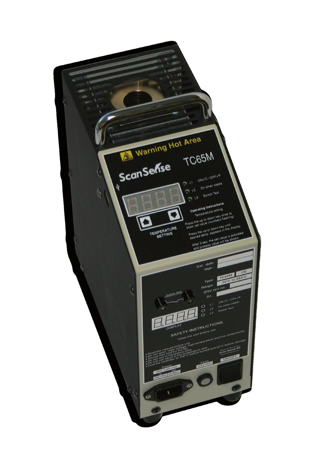


1 TC65M/15M TEMPERATURE CALIBRATOR USER S MANUAL
2 Thank you for purchasing a Scan-Sense temperature calibrator. The products are manufactured by Scan-Sense AS in accordance with our high quality standards in design, choice of components and workmanship in order to achieve maximum customer satisfaction and to fulfil our vision to be our customers First Choice. The TC65M/15M is designed and manufactured by: Scan-Sense AS Tel: Bekkeveien 163 Fax: N-3173 Vear Web: NORWAY post@scansense.no Scan-Sense AS reserves the right to make improvments or alterations to our products without incurring any responsibility to make the same improvments or alterations to products previously sold. SCAN-SENSE AS All rights reserved. No part of this publication may be reproduced, stored in a retrieval system, or transmitted in any form by any means, electronic, mechanical, photocopying, recording, or otherwise without the prior permission of Scan-Sense AS. All efforts have been made to ensure the accuracy of this handbook. We at Scan-Sense are always striving to improve our products and handbooks, therefore we would greatly appreciate being informed of any errors found in our product or in its manual. The above notwithstanding, Scan-Sense can assume no responsibility for any errors in this handbook or of their consequenses.
3 Contents 1. Getting started FAST! Safety Why calibrate? How often do I calibrate? How to use the TC65M/15M calibrator Maintenance Specifications Trouble shooting Warranty Appendix... DNV Certificate no. Page 3 Page 4 Page 5 Page 6 Page 7 Page 10 Page 10 Page 11 Page 11 Page 12 2
4 Getting started FAST! Don t start a fire!! Read the safety chapter for your own and your environments safety. Read the chapter Introduction to calibration if you do not have the full and whole understanding of the use of dry well calibrator as the TC65M/15M. 1. Make sure the supply voltage is in accordance with the description on the label. 2. Make sure the calibrator well and the probe you want to calibrate is clean. 3. Place the probe in an appropriate hole in the well*. 4. Turn on the calibrator. 5. The display on the calibrator controller will show the actual well temperature and the set point will show 25 C. Default is shown as C. See chapter 5. for switching the display to show F. 6. Press the up and down buttons multiple times on the controller in order to set the desired calibration temperature (set point). The display will automatically switch to show the set point when the up/down buttons are pressed. When pressing and holding one of these buttons the display will start to count up or down. If the buttons are held continuously, the counting speed will increase. The set point will not be active before you move to the next step. 7. After setting the set point, the display will return back to show actual well temperature 3 seconds after the last depressing of the set buttons. You can now switch between set point and well temperature by pressing the set button once. This will not affect the set point or anything else in the process. 8. Let the temperature reach and stabilize at the set point. Check both the calibrator and calibration object to determine if the temperature is stabile. 9. When both the calibrator and calibration object is stabile, note both readings. 10. Set the next calibration point with the up/down buttons and repeat point 5 to When all desired calibration points are completed, set the set point to 25 C and let the well temperature decrease to a temperature below 50 C before you store the calibrator. 12. File the calibration data. * If your probe has another diameter than those supplied, use an insert adapter, drilled to the correct diameter. A more thorough description of the above points is found in the chapter How to use the TC65M/15M calibrator. 3 TC65M/15M User s manual
5 Safety Incorrect use of dry well calibrators like the TC65M/15M can be hazardous. Severe burns or fire may very easy be the result of incorrect use. Therefore always see to that the assigned operators got the required skills to operate the calibrator. Local fire and safety instructions may apply to the use of instruments like the TC65M/15M. The well in the calibrator can reach up to 650 C. This temperature will certainly cause burns and fire if something gets into the well. Ensure that the workspace around and above the TC65M/15M is free from loose materials that can catch fire. There should be nothing but the roof above the calibrator (or at least 1m of clearance to a non flammable material). The greatest risk is if the probe or insert adapter is removed from the well when the calibrator still is hot. NEVER REMOVE HOT PROBES OR INSERTS FROM THE WELL. Allow time to cool down the probe and insert before removing and storing. Never remove the cover of the calibrator unless you are a qualified service technician. High voltages and temperatures will be exposed. Always ensure that the air inlet in the bottom of the TC65M/15M is free and not clogged by dust. Ensure that the fan is running. If not, do not use the TC65M/15M as it will overheat and create a potential danger. Send the TC65M/15M for repair. Ensure that the TC65M/15M and especially the well, is clean and free for dust before use. Some dry block calibrator users insist on using oil in the well to ensure better thermal contact. If your unit has been filled with oil, thoroughly clean the well for all traces of oil. Fumes from heated oil can be dangerous. Health damages, fire and explosion may be the result. Oil remains can also create a carbon buildup in the well (at high temperatures) that is nearly impossible to remove. WARNING! If a wet object is inserted into a heated well, the TC65M/15M may explode! The well can act as a launching tube for the probe and insert if undesired liquids or materials gets into the well. Never leave a powered calibrator. Always work with the calibrator on a sturdy workspace. In addition to the listed safety concerns, always add a good portion of common sense to catch up unpredictable safety risks. 4
6 Why calibrate? The definition of the term calibration is: To determine the difference between the object being calibrated with a known reference and knowing the uncertainty in the process. Adjusting the calibrated object in order to remove the error is of secondary importance as long as the error is either within acceptable limits or the error is used to calculate the real value. Calibration is an important part of any quality insurance routines. When a calibration routine is created, all aspects are taken into consideration by qualified personal so when an operator is making calibrations later, the process is done the same way every time and ensuring that the results are comparable and reliable. By documenting the process and results, you are making the whole process traceable. This way a lot of human errors can be eliminated, giving the responsible operator piece of mind if something goes wrong. Good quality is to achieve the accuracy you need and not far beyond. If your demand is to keep the temperature in you process within e.g. 300 to 330 C, define your accuracy needs to 315 +/-15 C. Your calibration process should now ensure that your temperature instrument is within these limits and not necessarily the peak performance of the specifications of the instrument. A good rule of thumb is to double the accuracy demand for your calibration compared to the process accuracy demand. This leaves the accuracy demand for you calibration in the neighborhood of +/-8 C. 5
7 The whole chain of elements involved in the calibration process creates errors in the final reading. In this matters errors are expressed as uncertainty. Take the following elements into account when considering the total uncertainty: Temperature drift in the calibrator Temperature drift in the calibrated instrument Temperature gradients in the calibrator well Differences in gradients caused by variance in probe mass (calibration object) Inaccuracy in the calibrator Inaccuracy in the calibration object Variance in thermal contact between the probe being calibrated and the calibrator well Reading error (if analog scale on the calibrating object) Remember all these elements are NOT added to calculate final uncertainty. In real life there is not likely that all uncertainty elements will be at the maximum and in the same direction simultaneously! Therefore another way of calculation is used. The formula is simple, but this is as far as we will go in this manual. There is a lot of written material covering this issue on the market. How often do I calibrate? Depending on the importance of the accuracy in the process and the use (or abuse) of the measuring equipment, the calibration intervals will vary. The calibrating should take place in intervals no longer than what you can handle if the process becomes out of specified limits. If a calibration suddenly reveals a large deviation compared to the previous calibration, you can trace back and identify the time span where errors may have occurred and take actions thereafter. The shorter the calibration interval, the shorter time span with possible errors. A normal interval for calibrating a thermometer in a process should be about 1-3 months. If there is very important to ensure the consistency of the accuracy, make simplified calibrations between scheduled calibrations with less calibration points (maybe only one) and simplified documentation. 6
8 How to use the TC65M/15M calibrator We assume that you know the basic operation of the calibrator as described in the Get started fast chapter. Here we are taking the points a bit further step for step. 1. Make sure the calibrator well and the probe you want to calibrate is clean. This is important in order to remove unnecessary uncertainty in the process created by carbon build up (above 500 C) and excessive pollution. Also polluted well and probe can create poisonous gases. If calibrating an electronic instrument, also make sure the contacts between the probe and display unit is clean. Dirty contacts create resistance that affects the reading. 2. Place the probe in an appropriate hole in the well*. Use a hole in well that is 0,2 to 0,6mm larger than the probe you are calibrating. If no appropriate hole exists, use an insert adapter placed in the largest hole. Insert adapters are available with several dimensions. There is also important that the probe reaches the bottom of the well. If not the reading will be very inaccurate. 3. Turn on the calibrator. Self-explanatory. 4. The display on the calibrator controller will show the actual temperature in the well The default temperature when powering up will be the set point 25 C. The display can be changed between C and F by pressing both set buttons when power is switched on. The selection will be stored when turning on the unit next time. The L1 indicator will show the chosen unit. The switch test indicator will be indicated by L3. When a stable temperature is reached, the L2 indicator point will stop flashing and light continuously. There will always be a difference in the actual well temperature and the display reading. This is due to temperature gradients in the well. This difference is largest during temperature increase and decent. The TC65M/15M internal reference sensor is located, close to the bottom of the well so the correct calibration depth is 1 to 2 cm from the bottom of the well. TC65M/15M is calibrated with a 6mm PRT reference probe placed at the bottom of the insert with 6,5mm hole. 7
9 Also take into consideration the load the calibration object will employ to the well. A large and heavy probe will extract more heat from the well and change the gradient lines differently compared with a small and light probe. 5. Press the up and down buttons on the controller in order to set the desired calibration temperature (setpoint). The display will automatically switch to show the set point when the up/down buttons are pressed. When pressing and holding one of these buttons the display will start to count up or down. If the buttons are held continuously, the counting speed will increase. The setpoint will not be active before you move to the next step. 6. After setting the set point, the display will return back to show actual well temperature 3 seconds after the last depressing of the set buttons. You can now switch between set point and well temperature by pressing the set button once. This will not affect the set point or anything else in the process. 7. Let the temperature reach and stabilize at the setpoint. Check both the calibrator and calibration object to determine if the temperature is stabile. During temperature rise and decent there will be a large difference in the well temperature displayed and the actual well temperature. There will also be a large difference in the actual well temperature and the temperature displayed on the calibration object. Therefore the temperature has to equalize. Also allow 5 to 10 minutes for the process to stabilize after reaching the desired setpoint before making readings. 8
10 8. When both the calibrator and calibration object is stabile, note both readings. When the process is stabile as described in the previous point, note the reading of both the calibrator and the calibrating object. Make calculations for each point that will give you the factor for calculating a more accurate value than the reading of the calibrated object. Refer to the provided example for a calibration certificate with report. 9. Set the next calibration point with the up/down buttons and repeat point 5 to 8. To give the best repeatability we suggest always starting with the lowest calibration point and work your way upward. Select calibration points that are relevant i.e. If your target area in the process is 130 to 200 C, logical calibration points would be 100, 175 and 250 C. A simplified process would be only 150 C that may be used as a control calibration between scheduled calibrations. 10. When all desired calibration points are finished, set the setpoint to 25 C and let the well temperature fall to below 50 C before you store the calibrator If you remove the calibrated probe from a very hot well, it will be prone to damage (if Pt type) and it may be dangerously hot to touch. The heating element will automatically be switched off in case set temperature of 400 C or more has been in operation for more than 1 hour. The display will in this case show E40 and a new set point must be selected before continuing. 11. Test of thermostats. The TC65M/125M have a built-in test functions for thermostats. Connect the alligator clips to the calibrators input function. Please pay attention to the fact that thermostats react slowly to temperature changes. 9
11 Maintenance To ensure acceptable dependability we suggest annual calibration of the TC65M/15M calibrator. Also make sure the calibrator is stored and handled such a way that it is likely not to suffer from abuse. Keep the calibrator clean and dry at all times. Polluted well will decrease accuracy. Clean the holes with a small wire brush or sand paper on a piece of wire. Remove dust from the well and internals with compressed air. This is important in order to avoid fire. Also regularly compare the latest calibration with earlier in order to monitor if there is a trend going in a certain direction. If a trend is accelerated or radically altered, there may be wise to keep a closer eye at the calibrator and maybe calibrate it more often or have it examined. This also applies to your calibration objects. TC65M/15M is a dry well calibrator. Do not use oil in the well holes. There are no user serviceable parts inside the calibrator. However, there is a 15A main fuse inside that may brake due to internal failure. A qualified service person should be able to determine if the fuse can be replaced wit no other actions or if the calibrator needs repair. Technical information TC65M TC15M Temperature range 30 to 650 C -40* to 150 C Resolution (display) 0,1 C 0,1 C Accuracy ± 1,5 C ± 0,3 C Stability ± 0,5 C ± 0,05 C Heating time to max 40 min. 50 min. Cooling time to min 65 min. 20 min. Thermostat test Yes Yes USB Yes Yes Well depth 155 mm 110 mm Well diameter 26 mm 19 mm Power supply 230 VAC, 50 Hz VAC, 60/50Hz 110VAC, 60 Hz Power consumpsion 1600 Watt 180 Watt Operating temp. 0 to 40 C 0 to 40 C Dimension 117 x 300 x 245 mm 117 x 300 x 245 mm Weight Approx. 5.5 kgs Approx. 5.5 kgs 10
12 Trouble shooting Unstability may occur if the mains supply voltage varies. This is sometimes the case if the stability seems to be erratic for no reason. Warranty Scan-Sense standard warranty conditions. 11
13 Appendix The calibration certificate template may be used in most cases for your calibraion objects. Make copies of the page and fill in your own calibration results. This is an explanation to the suggested points in the template: (most are self explanatory and are not further described). The Certificate number shall be a unique notification for the certificate making it possible to separate certificates even if they cover the same calibration object. Note this number on a small sticker on the calibration object making it possible to trace the calibration. In the first table note the data about the object you are calibrating. Calibration conditions notes the temperature in the room during calibration. This may in extreme cases inflict the results. The Statement in the template states that the calibrator has a traceable calibration. In order to use this statement, make sure your calibrator really do have a valid traceable calibration. Better yet, also a written instruction describing how to maintain the calibrator. In the column Standard used note the serial number for your TC65M/15M unit. Also note the number at the certificate for the latest calibration of your TC65M/15M calibrator and the name of the company or organization that performed the calibration. This way you will maintain the traceability all the way from your calibration object to the interna tional standard on top of the reference chain. Remember to update this number when your TC65M/15M has been calibrated. In the Measuring report table there is a column TC65M/15M correction that may be filled in if you have a calibration certificate for your TC65M/15M stating measuring errors. By calculating the TC65M/15M real value you will achieve better accuracy. The Measuring report will at the last column state the error for the calibration object. This error should be considered if it is within acceptable limits and can be ignored, or if the value must be used to calculate a more accurate value. At the bottom of the certificate the operator performing the calibration putting he s or her sign. The person responsible for the correctness of the process and calculations are also signing the certificate. 12
14 Certificate of Calibration TC65M/15M User s manual Certificate number:.. Unit under test: Serial number: Calibration result: Department: Passed: Calibration Date: Calibration due date: Failed: Calibration conditions: Temperature: Statement: The instrument described above has been calibrated using the below described standard that is calibrated with traceability to international standards. This calibration certificate is issued with a measuring report, and shall only be fully reproduced. Standard used: Instrument: Temp. calibrator Model: TC65M/15M Serial No: Cert No: Traceability: Measuring report: TC65M/15M reading: TC65M/15M correction: TC65M/15M real value: Test object reading: Test object deviation: Remarks: Test object deviation is calculated by subtracting TC65M/15M real value from Test object reading. The value Test object deviation tells how much the reading of the test object is off. A positive figure tells how much the reading is above the actual value. A negative figure tells how much below Calibration performed by:.. 13 Certified by:..
15 Manual revision: Januar 2009 PS00080A Copyrighted 2009 Scan-Sense AS
Calculating Total Uncertainty of Temperature Calibration with a Dry Block. Calibration White Paper. Beamex.
 Beamex Calibration White Paper info@beamex.com Calculating Total Uncertainty of Temperature Calibration with a Dry Block World-class calibration solutions Calculating Total Uncertainty of Temperature Calibration
PM105 PRESSURE METER USER S MANUAL
 PM105 PRESSURE METER USER S MANUAL Manual revision: 15 March, 2001 SCSMANP015 Copyrighted 2001 Thank you for purchasing a Tek Know pressure meter. The Tek Know products are manufactured by Scan-Sense AS
Operating Instructions Part No
 DIGITAL AUTOMATIC TYRE INFLATOR Operating Instructions Part No. 11.0578 Thank you for selecting this Jamec Pem Automatic Tyre Inflator. Please read this manual before carrying out any installation or service
Thermo Probe, Inc. TP-5 TP-7 TP-8. Instruction Manual English. Switch. Display. Carry Strap. Probe. Ground Clip. Switch. Display.
 Display Thermo, Inc. Instruction Manual English TP-5 Display TP-7 Display TP-8 1-1 Thermo, Inc. Instructions for use- Models TP-5, TP-7, and TP-8 The manual describes basic function and use of Thermo instruments
Constant Pressure Inlet (CCN) Operator Manual
 Operator Manual") Constant Pressure Inlet (CCN) Operator Manual DOC-0125 Revision J 2545 Central Avenue Boulder, CO 80301-5727 USA C O P Y R I G H T 2 0 1 1 D R O P L E T M E A S U R E M E N T T E C H N O L O G I E S, I
Constant Pressure Inlet (CCN) Operator Manual DOC-0125 Revision J 2545 Central Avenue Boulder, CO 80301-5727 USA C O P Y R I G H T 2 0 1 1 D R O P L E T M E A S U R E M E N T T E C H N O L O G I E S, I
Portable Gas Monitor GX User Maintenance Manual (H4-0050)
") H4E-0050 Portable Gas Monitor GX-8000 User Maintenance Manual (H4-0050) Need of Maintenance and Servicing This gas monitor must be maintained in a normal state at all times to prevent accidents due to
H4E-0050 Portable Gas Monitor GX-8000 User Maintenance Manual (H4-0050) Need of Maintenance and Servicing This gas monitor must be maintained in a normal state at all times to prevent accidents due to
Installation Procedure Esco Miri Multi-Room Incubator
 Esco Miri Multi-Room Incubator Version 1.1 ESCO MEDICAL Esco Micro Pte Ltd 21 Changi South Street 1 Singapore 486777 Tel. : +65 6542 0833 Fax : +65 6542 5732 / 6546 2913 Mail : csis-medical@escoglobal.com
Beamex. Calibration White Paper. Weighing scale calibration - How to calibrate weighing instruments
 Beamex Calibration White Paper info@beamex.com Weighing scale calibration - How to calibrate weighing instruments Weighing scale calibration - How to calibrate weighing instruments Weighing scales, weighing
SPECIFICATIONS APCEPH1
 APCEPH1 ph CONTROLLER SPECIFICATIONS APCEPH1 Input voltage 120 Volts AC Maximum amperage 14.5 amps @ 120 VAC ph Accuracy +/- 0.2 ph ph Control range Adjustable 4.5 8.5 ph Weight < 1 lbs Dimensions 3" x
EC214 EC215 - EC215R Bench Conductivity Meters
 Instruction Manual EC214 EC215 - EC215R Bench Conductivity Meters http://www.hannainst.com These Instruments are in Compliance with the CE Directives Dear Customer, Thank you for choosing a Hanna Instruments
HumiSys HF High Flow RH Generator
 HumiSys HF High Flow RH Generator Designed, built, and supported by InstruQuest Inc. Versatile Relative Humidity Generation and Multi-Sensor System The HumiSys HF is a high flow version of the previously
General Accreditation Guidance. User checks and maintenance of laboratory balances
 General Accreditation Guidance User checks and maintenance of laboratory balances January 2018 Copyright National Association of Testing Authorities, Australia 2010 All intellectual property rights in
L 100. Bubble-Tube Level System. Installation, Operation and Maintenance Instructions
 L 100 Bubble-Tube Level System Installation, Operation and Maintenance Instructions Figure 1 Contents Section Description Page 1.0 Introduction 2 2.0 Specifications 3 3.0 Installation 3 4.0 Warranty 6
Sensoric 4-20 ma Transmitter Board Operation Manual
 Sensoric 4-20 ma Transmitter Board Operation Manual 1 Content Features Operation Manual Technical Data Mechanical Dimensions Remarks & Contact information 2 Features Soldered sensor cell (non replaceable)
OC Panel High Limit Aquastat Kit, Manual Reset p/n
 OC Panel High Limit Aquastat Kit, Manual Reset p/n 233202 Instruction Sheet APPLICATION The OC (Option Control) Panel High Limit Aquastat Kit provides electronic temperature sensing in a UL limit-rated
HI 2314 HI 2315 HI 23151
 Instruction Manual HI 2314 HI 2315 HI 23151 Multi-Range Conductivity Meters for Laboratories www.hannainst.com Dear Customer, Thank you for choosing a Hanna Instruments product. Please read this instruction
Electro-Pneumatic Converter YT-940 SERIES
 Electro-Pneumatic Converter YT-940 SERIES PRODUCT MANUAL VERSION 1.00 Contents 1. Introduction 3 1.1 General information for the users. 3 1.2 Manufacturer Warranty 3 1.3 Explosion Proof Warning. 4 2. Product
AUTOMATIC TIRE INFLATOR # MW-60, MW-60-4WAY & MW-64HP
 USER MANUEL AUTOMATIC TIRE INFLATOR # MW-60, MW-60-4WAY & MW-64HP TIRE EQUIPMENT MANUFACTURER 1.866.409.RACK WWW.MARTINSINDUSTRIES.COM info@martinsindustries.com PARTS Verify that the following components
CDS-2000 CO 2 Sensor Verification, Calibration, and Troubleshooting Bulletin
 Electronic Control Manual 216 Sensors and Stats Section S Technical Bulletin CDS-2000 Issue Date 0393 CDS-2000 CO 2 Sensor Verification, Calibration, and Troubleshooting Bulletin Introduction 3 Pre-Verification
3 GALLON, OILLESS PANCAKE COMPRESSOR INSTRUCTIONS. Item #31289
 3 GALLON, OILLESS PANCAKE COMPRESSOR INSTRUCTIONS Item #31289 The EASTWOOD 3 GALLON, OILLESS PANCAKE COMPRESSOR, with an Integral Air Regulator, efficiently supplies all compressed air requirements for
Digital Melting Point Apparatus
 Digital Melting Point Apparatus Heating Plateau Ramping Start/Stop Plateau set Ramp stop Hold User Guide Version 1.1 Heating Viewing tube Sample Chamber IEC power inlet socket Power on/off Temperature
Best Practice for Calibrating LTH Conductivity Instruments
 Application Note Best Practice for Calibrating LTH Conductivity Instruments As accurate process measurement becomes an everyday requirement it is vital to be able to calibrate conductivity instruments
Rigel 601 CHECKBOX. Instruction Manual. 348A551 Issue 2.0. April Seaward Electronic Ltd. Issue 2.0
 Rigel 601 CHECKBOX Instruction Manual 348A551 Issue 2.0 April 2006 2006 Seaward Electronic Ltd. Issue 2.0 Limited Warranty & Limitation of Liability Rigel Medical guarantees this product for a period of
The HumiSys. RH Generator. Operation. Applications. Designed, built, and supported by InstruQuest Inc.
 The HumiSys RH Generator Designed, built, and supported by InstruQuest Inc. Versatile Relative Humidity Generation and Multi-Sensor System The new HumiSys with single or dual RH probes capabilities is
UNDERSTANDING, ACCELERATED
 UNDERSTANDING, ACCELERATED MEASURE FLOW, PRESSURE, AND TEMPERATURE ALL IN ONE INSTRUMENT! Designed for Performance TSI thermal mass flowmeters incorporate a proprietary platinum film sensor design for
DTG - LCD Digital Temperature Gauge USER MANUAL
 DTG - LCD USER MANUAL Page 1 of 7 USERS GUIDE page 1. Description 3 2. Function 3 3. Safety Instruction 3 3.1. Safety Conventions 3 3.2. Proper Use 3 4. Installation 4 4.1. Unpacking 4 4.2. Storage 4 4.3.
Operating Instructions Part No
 DIGITAL AUTOMATIC TYRE INFLATOR Operating Instructions Part No. 11.0545 Thank you for selecting this Jamec Pem Automatic Tyre Inflator. Please read this manual before carrying out any installation or service
Operation Instruction Manual
 Full Automatic Intelligent Digital Tire Nitrogen Machine FS-6000B Operation Instruction Manual Please read this manual before carrying out any assembly or service procedures. 1 I. Introduction Contents
444C DUAL PERFORMANCE VALUE PACK
 (Chrome) PART NO. 44432 IMPORTANT: It is essential that you and any other operator of this product read and understand the contents of this manual before installing and using this product. SAVE THIS MANUAL
OxyScan Graphic. Operating Instructions. UMS Micro-oxygen sensor 501. Microprocessor instrument
 OxyScan Graphic Operating Instructions UMS Micro-oxygen sensor 501 Microprocessor instrument Introduction Thank you for choosing the UMS Micro Oxygen Sensor 501 - a highly advanced product! Please read
Ambient Weather WS-03 Thermo-Hygrometer
 Ambient Weather WS-03 Thermo-Hygrometer Table of Contents 1. Introduction... 1 2. Parts List... 1 2.1 Display Console Set Up... 1 2.2 Sensor Operation Verification... 2 2.3 Display Features... 3 2.3.1
9101 Zero Point Dry-Well
 9101 Zero Point Dry-Well User Manual Rev. 4A0801 Hart Scientific, LLC 799 E. Utah Valley Drive American Fork, UT 84003-9775 USA Phone: +1.801.763.1600 Telefax: +1.801.763.1010 E-mail: support@hartscientific.com
Hot extractive multi-channel gas analyser for continuous process and emissions monitoring.
 Product Data Sheet CODEL Continuous Emission Monitoring GCEM4100 Extractive Gas Analyser CO, CO2, NO, NO2, SO2, HCL, CH4 & H2O Hot extractive multi-channel gas analyser for continuous process and emissions
Hot extractive multi-channel gas analyser for continuous process and emissions monitoring.
 Product Data Sheet CODEL Continuous Emission Monitoring GCEM4100 Extractive Gas Analyser CO, CO2, NO, NO2, SO2, HCL, CH4 & H2O Hot extractive multi-channel gas analyser for continuous process and emissions
Technical Data Sheet MF010-O-LC
 Technical Data Sheet MF010-O-LC - 1 - 1. Properties The oxygen measuring system MF010-O-LC determines the oxygen content in gas mixtures up to a temperature of 250 C. It is particularly suitable for the
Instruction Manual Dräger MSI P7 and MSI P7 plus
 Dräger MSI GmbH Rohrstraße 32 58093 Hagen Tel.: +49-2331 / 9584-0 Fax: +49-2331 / 9584-29 e-mail: info@draeger-msi.de D 923; Edition 2011-01-01 Content 1. General Hints Page 4 2. The Instrument 2.1 Front
Operation manual Level sensor DC-LS-50 Operation Manual Level Sensor DC-LS-50
 Operation Manual Level Sensor DC-LS-50 Rev.02 (2014.06) OL Page 1 of 8 Table of contents I. STRUCTURE OF THE MANUAL / CLARIFICATION... 3 II. SAFETY AND HEALTH CONCERNS... 4 1 INTRODUCTION... 5 1.1 Use
Basic Nitriding Sampling System Hydrogen Analyzer with Calculated % DA, % NH 3, and K N Values. Operations Manual
 Basic Nitriding Sampling System Hydrogen Analyzer with Calculated % DA, % NH 3, and K N Values Operations Manual Please read, understand, and follow these instructions before operating this equipment.
User's Manual. Heavy Duty Dissolved Oxygen Meter. Model
 User's Manual Heavy Duty Dissolved Oxygen Meter Model 407510 Introduction Congratulations on your purchase of Extech's Heavy Duty Dissolved Oxygen / Temperature Meter which simultaneously displays Dissolved
Storage Shelving. User Manual [Revision 3.0 May 2017]
![Storage Shelving. User Manual [Revision 3.0 May 2017]](/thumbs/90/103875414.jpg "Storage Shelving. User Manual [Revision 3.0 May 2017]") User Manual [Revision 3.0 May 2017] READ THIS MANUAL CAREFULLY BEFORE USE FAILURE TO DO SO MAY RESULT IN INJURY, PROPERTY DAMAGE AND MAY VOID WARRANTY. KEEP THIS MANUAL FOR FUTURE REFERENCE. Products covered
User Manual [Revision 3.0 May 2017] READ THIS MANUAL CAREFULLY BEFORE USE FAILURE TO DO SO MAY RESULT IN INJURY, PROPERTY DAMAGE AND MAY VOID WARRANTY. KEEP THIS MANUAL FOR FUTURE REFERENCE. Products covered
AMT-Ex Dewpoint Transmitter
 AMT-Ex Dewpoint Transmitter Instruction Manual Alpha Moisture Systems Alpha House 96 City Road Bradford BD8 8ES England Tel: +44 1274 733100 Fax: +44 1274 733200 email: mail@amsytems.co.uk web: www.amsystems.co.uk
Manual of SF6 Comprehensive Tester
 Manual of SF6 Comprehensive Tester Important Description All the staff taking in charge of the usage or maintenance of this product should carefully read this manual. The same as any other complicated
Pneumatic high-pressure controller Model CPC7000
 Calibration technology Pneumatic high-pressure controller Model CPC7000 WIKA data sheet CT 27.63 Applications Healthcare and avionics industry Industry (laboratory, workshop and production) Transmitter
Pneumatic high-pressure controller Model CPC7000
 Calibration technology Pneumatic high-pressure controller Model CPC7000 WIKA data sheet CT 27.63 Applications Automotive and avionics industry Industry (laboratory, workshop and production) Transmitter
SAUTER FK Version /2016 GB
 Sauter GmbH Ziegelei 1 D-72336 Balingen E-Mail: info@sauter.eu Tel: +49-[0]7433-9933-199 Fax: +49-[0]7433-9933-149 Internet: www.sauter.eu Instruction Manual Digital Force Gauge SAUTER FK Version 1.4 12/2016
LOCK UP VALVES YT-400/405/430/435 SERIES
 LOCK UP VALVES YT-400/405/430/435 SERIES PRODUCT MANUAL VERSION 1.00 Contents 1. Introduction 3 1.1 General information for the users. 3 1.2 Manufacturer Warranty 3 2. Product Description.. 4 2.1 General..
Specific Accreditation Criteria Calibration ISO IEC Annex. Mass and related quantities
 Specific Accreditation Criteria Calibration ISO IEC 17025 Annex Mass and related quantities January 2018 Copyright National Association of Testing Authorities, Australia 2014 This publication is protected
Instruction and Maintenance Manual
 Instruction and Maintenance Manual GRYF OXY ZM 02/100/2 E Contact GRYF HB, spol. s r.o. Cechova 314 Havlickuv Brod 580 01 tel.: +420 569 426 627 fax: +420 569 426 627 www.gryf.eu ver.: 11.2.2015 OEM module
Bante810 Benchtop Dissolved Oxygen Meter Instruction Manual
 Bante810 Benchtop Dissolved Oxygen Meter Instruction Manual BANTE INSTRUMENTS CO., LTD Bante810 Benchtop Dissolved Oxygen Meter 1 Introduction Thank you for selecting the Bante810 benchtop dissolved oxygen
Digital Vacuum Regulator
 Temperature Control for Research and Industry Digital Vacuum Regulator User s Manual Model DVR-380 INDEX SECTION PAGE SAFETY NOTICES................................................. 3 1. QUICK OPERATING
Pegas 4000 MF Gas Mixer InstructionManual Columbus Instruments
 Pegas 4000 MF Gas Mixer InstructionManual Contents I Table of Contents Foreword Part I Introduction 1 2 1 System overview... 2 2 Specifications... 3 Part II Installation 4 1 Rear panel connections...
VOLUME BOOSTER RELAYS YT-300 / 305 SERIES
 VOLUME BOOSTER RELAYS YT-300 / 305 SERIES PRODUCT MANUAL VERSION 1.02 Contents 1. Introduction 3 1.1 General information for the users. 3 1.2 Manufacturer Warranty 3 2. Product Description.. 4 2.1 General..
973-SF 6 Analyzer. Precise and Stable SF 6 Gas Analyzer REFLECTING YOUR STANDARDS
 Precise and Stable SF 6 Gas Analyzer Simultaneous measurement of humidity, SF 6 purity and SO 2 concentration Integrated gas recovery system with automatic pump back Fully automated SF 6 gas testing Fundamental
Title: Standard Operating Procedure for R&R Environmental Devices Model MFC201 Gas Dilution Calibrator
 Procedure No: SOP-029 Revision No: 1.1 (December 29, 2010) Page No.: 1 of 7 1. INTRODUCTION AND SCOPE To obtain timely data for the purpose of air quality assessment, air quality trend reporting, air quality
628 Differential Pressure Decay Leak Tester
 628 Differential Pressure Decay Leak Tester The 628 puts Uson s industry leading differential pressure decay sensitivity in your hands and in your budget with no compromise in quality, reliability, and
400C & 450C DUAL PERFORMANCE VALUE PACKS
 (Chrome) PART NO. 40013 (Silver) PART NO. 45012 (Chrome) PART NO. 45013 IMPORTANT: It is essential that you and any other operator of this product read and understand the contents of this manual before
CO, NO, NO 2, NO x, SO 2, CH 4, HCl, CO 2 & H ² O. Extractive low cost, low maintenance devices for continuous process and emissions monitoring.
 Product Data Sheet CODEL Continuous Emission Monitoring GCEM 40 Series Extractive Gas Analyser CO, NO, NO 2, NO x, SO 2, CH 4, HCl, CO 2 & H ² O Extractive low cost, low maintenance devices for continuous
Columbus Instruments
 0215-003M Portable O 2 /CO 2 /CH 4 Meter User s Manual Columbus Instruments 950 NORTH HAGUE AVENUE TEL:(614) 276-0861 COLUMBUS, OHIO 43204, USA FAX:(614) 276-0529 1 www.colinst.com TOLL FREE 1-800-669-5011
BUBBLER CONTROL SYSTEM
 BUBBLER CONTROL SYSTEM Description: The HDBCS is a fully automatic bubbler system, which does liquid level measurements in water and wastewater applications. It is a dual air compressor system with, air
TR Electronic Pressure Regulator. User s Manual
 TR Electronic Pressure Regulator Page 2 of 13 Table of Contents Warnings, Cautions & Notices... 3 Factory Default Setting... 4 Quick Start Procedure... 5 Configuration Tab... 8 Setup Tab... 9 Internal
CÜBE. User Manual. American Weigh Scales. CUBE-100 (100g x 0.01g) CUBE-650 (650g x 0.1g)
 CUBE-650 (650g x 0.1g)") American Weigh Scales CÜBE User Manual CUBE-100 (100g x 0.01g) CUBE-650 (650g x 0.1g) Copyright 2014 American Weigh Scales, Inc. All rights reserved. Rev. 1.0 CUBE Manual Thank you for purchasing the American
American Weigh Scales CÜBE User Manual CUBE-100 (100g x 0.01g) CUBE-650 (650g x 0.1g) Copyright 2014 American Weigh Scales, Inc. All rights reserved. Rev. 1.0 CUBE Manual Thank you for purchasing the American
Operating instructions Installation instructions To be kept in the vehicle!
 ON OFF Sonatic Sonatic Level indicator for gas cylinders (Type GB) h Operating instructions Installation instructions To be kept in the vehicle! Service (UK and Eire) Tel. (0 12 83) 51 10 92 Fax (0 12
The HumiPyc ( Model 2) - Gas Pycnometer; Density, Moisture, Permeation Analyzer; Filter Integrity Tester; RH sensor Calibrator
 - Gas Pycnometer; Density, Moisture, Permeation Analyzer; Filter Integrity Tester; RH sensor Calibrator") The HumiPyc ( Model 2) - Gas Pycnometer; Density, Moisture, Permeation Analyzer; Filter Integrity Tester; RH sensor Calibrator Designed, built, and supported by InstruQuest Inc. Universal pycnometer, no
The HumiPyc ( Model 2) - Gas Pycnometer; Density, Moisture, Permeation Analyzer; Filter Integrity Tester; RH sensor Calibrator Designed, built, and supported by InstruQuest Inc. Universal pycnometer, no
Mini-Pro CO2 Sensor User s Manual - ANALOG MODEL -
 Mini-Pro CO2 Sensor User s Manual - ANALOG MODEL - Table of Contents 1. Introduction 3 2. Instrument Setup 4 2.1 Instrument Checklist 4 2.2 Optional Accessories 4 2.3 Gas Concentration Ranges Available
Do Not Print This Page.
 Do Not Print This Page. Load 1 sheet of cardstock paper. Print Page 2 - the cover For the body of the text, load 3 sheets of 28lb matte finish paper into the printer. Print pages 3, 5, 7 (Sheet 1, 2, 3)
KERN EG/EW Version /02
 E KERN EG/EW Version 1.5 07/02 Operating Instructions Electronic Precision Balances Contents 1 TECHNICAL DATA... 20 2 UNPACKING AND STANDARD ACCESSORIES... 23 3 SETTING UP THE BALANCE... 23 4 EXTERNAL
Cover Page for Lab Report Group Portion. Pump Performance
 Cover Page for Lab Report Group Portion Pump Performance Prepared by Professor J. M. Cimbala, Penn State University Latest revision: 02 March 2012 Name 1: Name 2: Name 3: [Name 4: ] Date: Section number:
analytical bulk flow distance FLOW level pressure temperature industrial communication
 analytical bulk flow distance level pressure temperature industrial communication isolv THERMAL MASS METER Measuring Principle Self-heated Sensor Reference Sensor isolv Thermal Mass Flow Meters have two
The HumiPyc - Model 1 - Gas Pycnometer; Density, Moisture, Permeation Analyzer; RH sensor Calibrator
 The HumiPyc - Model 1 - Gas Pycnometer; Density, Moisture, Permeation Analyzer; RH sensor Calibrator Designed, built, and supported by InstruQuest Inc. Temperature controlled, multi-technique volumetric
Temperature Controllers
 IM0004 April 2013 CONTENTS T-12 Thermostat PAGE Introduction 1 Scope 1 Description 1 Specification 1 Temperature Controllers 2 INTRODUCTION CAUTION Prior to installing, the instructions provided herein
SANP ACTING RELAYS YT-520/525/530 SERIES
 SANP ACTING RELAYS YT-520/525/530 SERIES PRODUCT MANUAL VERSION 1.02 Contents 1. Introduction 3 1.1 General information for the users. 3 1.2 Manufacturer Warranty 3 2. Product Description.. 4 2.1 General..
Vaisala Pressure, RH & Temp. Transmitter. The instrument was operational upon receipt. The instrument was adjusted and calibrated.
 Asset #: 123 Calibration - Certificate No: 2083.01 Customer: Condition: Action Taken: Sample Inc. 123 Sample Rd. Sample, MA 01234 The instrument was operational upon receipt. The instrument was adjusted
How to specify a product. Process Sensors and Mechanical Instruments
 How to specify a product Process Sensors and Mechanical Instruments Keep the overview. Here is some guideline information on how to specify our products. Intended as supplementary help to specification
USER S INFORMATION MANUAL
 USER S INFORMATION MANUAL UPFLOW, DOWNFLOW, UPFLOW/HORIZONTAL & HORIZONTAL ONLY INDUCED DRAFT GAS FURNACES Recognize this symbol as an indication of Important Safety Information If the information in this
Instruction and Maintenance Manual
 Instruction and Maintenance Manual GRYF OXY Z 02/100/2 E Contact GRYF HB, spol. s r.o. Cechova 314 Havlickuv Brod 580 01 tel.: +420 569 426 627 fax: +420 569 426 627 Czech Republic www.gryf.eu Technical
400H HARDMOUNT AIR COMPRESSOR KIT PART NO H HARDMOUNT AIR COMPRESSOR KIT PART NO
 400H HARDMOUNT AIR COMPRESSOR KIT PART NO. 40042 450H HARDMOUNT AIR COMPRESSOR KIT PART NO. 45042 400H 450H IMPORTANT: It is essential that you and any other operator of this product read and understand
UsER manual for Watersens ph -REDOX
 UsER manual for Watersens -REDOX Cl 8 1 2 6 3 3 7 7 4 4 4 4 Parts List 1 Redox Probe 1 x 2 PH Probe 1 x 5 Tube Weight 2 x 6 Connection Valve 1 x chlorine 3 Chlorine and Pumps 2 x 7 Dosing Valve 2 x 5 5
DIGITAL AUTOMATIC TYRE INFLATOR
 DIGITAL AUTOMATIC TYRE INFLATOR Instruction Manual PSI Part No. 11.0556 Digital Automatic Tyre Inflator (Portable) Thank you for selecting our Digital Automatic Tyre Inflator (Portable), please read this
Requirements and Methods for Calibration of Equipment in Clinical Laboratories. NK Chan (HKRCBTS) 24 August 2007
 24 August 2007") Requirements and Methods for Calibration of Equipment in Clinical Laboratories NK Chan (HKRCBTS) 24 August 2007 1 Contents Basic Requirements of Equipment Calibration Calibration of Electronic Balance
Requirements and Methods for Calibration of Equipment in Clinical Laboratories NK Chan (HKRCBTS) 24 August 2007 1 Contents Basic Requirements of Equipment Calibration Calibration of Electronic Balance
OXY Integral. INTERCON ENTERPRISES INC Tel: Fax: Internet:
 OXY Integral INTERCON ENTERPRISES INC Tel: 800 665 6655 Fax: 604 946 5340 E-Mail: sales@intercononline.com Internet: www.intercononline.com Manual Integral 2006 1 INDEX 2-3 PREFACE 4 INTRODUCTION 5 Principle
H 2. Sensor Series Take no risk! Install a Hydrogen Sensor in your Gaschromatograph
 Sensor Series 9000 Take no risk! Install a Hydrogen Sensor in your Gaschromatograph Carrier Gases for GC Probably more than 90% of the present GC instruments run with helium as carrier gas. Some people
Operating Manual Body fat balance
 KERN & Sohn GmbH Ziegelei 1 D-72336 Balingen email: info@kern-sohn.com Phone: +49-[0]7433-9933-0 Fax: +49-[0]7433-9933-149 Internet: www.kern-sohn.com Operating Manual Body fat balance KERN MFB Version
E2K-L. Liquid Level Sensor That Is Unaffected by the Color of the Pipe or Liquid. Liquid Level Sensor. Ordering Information
 Liquid Level EK-L CSM_EK-L_DS_E 3 Liquid Level That Is Unaffected by the Color of the or Liquid Mount to bypass pipes. Fit a wide range of pipe diameters: 8 to mm or to mm Built-in Amplifiers to save space.
Sport Grouse PRO REMOTE CONTROL LAUNCHER INSTRUCTION MANUAL
 Visit our website for all your launcher dummies and launcher accessories for your Sport Grouse PRO Remote Launcher Sport Grouse PRO REMOTE CONTROL LAUNCHER INSTRUCTION MANUAL SAFETY FIRST This device fires
BCM-Series. User Manual. American Weigh Scales. BCM-100 (100g x 0.01g) BCM-650 (650g x 0.1g)
 BCM-650 (650g x 0.1g)") American Weigh Scales BCM-Series User Manual BCM-100 (100g x 0.01g) BCM-650 (650g x 0.1g) Copyright 2012 American Weigh Scales, Inc. All rights reserved. Rev. 1.2 BCM-Series Manual Thank you for purchasing
American Weigh Scales BCM-Series User Manual BCM-100 (100g x 0.01g) BCM-650 (650g x 0.1g) Copyright 2012 American Weigh Scales, Inc. All rights reserved. Rev. 1.2 BCM-Series Manual Thank you for purchasing
deltaflowc deltaflowc Venturi or Probe
 deltaflowc Mass Flowmeter for Gases - Multivariable with ultra fast dp, p and T-sensors - Compact, accurate and user-friendly - Ideal for OEMs deltaflowc Venturi or Probe Precise mass flow metering deltaflowc
5 Channel Calibrator
 212 N. Woodwork Lane Palatine, IL 60067 800-223-3977 5 Channel Calibrator Part # 0724 User Manual Questions? Contact us at 800-223-3977 or online at http://www.cleanair.com/equipment/express/main.html
The Univentor 1250 Anaesthesia Unit
 THE UNIVENTOR 1200/1250 ANAESTHESIA UNIT The Univentor 1250 Anaesthesia Unit TABLE OF CONTENTS EDITION 1 Section 1 - WARRANTY & SERVICE 1.1. WARRANTY 2 1.2. DAMAGED SHIPMENTS 2 1.3. SERVICE 2 Section 2
Datasheet: K-30 ASCII Sensor
 Datasheet: K-30 ASCII Sensor The K30 ASCII sensor is a low cost, infrared and maintenance free transmitter module intended to be built into different host devices that require CO2 monitoring data. The
FTC130 Transmitter. Operating Manual
 Seite 1 von 11 FTC130 Transmitter Fast Thermal Conductivity Analyzer Operating Manual 1.09KD180724CWI1V05 Messkonzept GmbH Seite 2 von 11 1. Intended Use... 3 2. Description... 4 3. Measuring gases and
MODEL GENERA PURGE TURBINE INSTR DANGER HIGHLY TOXIC AND OR FLAMMABLE LIQUIDS OR GASES MAY BE PRESENT IN THIS MONITORING SYSTEM.
 275R MODEL 275R POR ORTABLE TURBINE GENERA ENERATOR PURGE GAS ANAL NALYZER INSTR NSTRUCTION MANU ANUAL AL DANGER HIGHLY TOXIC AND OR FLAMMABLE LIQUIDS OR GASES MAY BE PRESENT IN THIS MONITORING SYSTEM.
MIL-STD-883G METHOD
 STEADY-STATE LIFE 1. PURPOSE. The steady-state life test is performed for the purpose of demonstrating the quality or reliability of devices subjected to the specified conditions over an extended time
AXIS. User Manual. American Weigh Scales. AXIS-100 (100g x 0.01g) AXIS-650 (650g x 0.01g)
 AXIS-650 (650g x 0.01g)") American Weigh Scales AXIS User Manual AXIS-100 (100g x 0.01g) AXIS-650 (650g x 0.01g) Copyright 2012 American Weigh Scales, Inc. All rights reserved. Rev. 1.0 AXIS Manual Thank you for purchasing the
American Weigh Scales AXIS User Manual AXIS-100 (100g x 0.01g) AXIS-650 (650g x 0.01g) Copyright 2012 American Weigh Scales, Inc. All rights reserved. Rev. 1.0 AXIS Manual Thank you for purchasing the
Reflow Oven HHL3000 INSTRUCTION MANUAL POHUA - jedyny autoryzowany przedstawiciel w Polsce
 POHUA - jedyny autoryzowany przedstawiciel w Polsce www.pohua.pl AOYUE TONGYI ELECTRONIC EQUIPMENT FACTORY Jishui Industrial Zone, Nantou, Zhongshan City, Guangdong Province, P. R. China www.aoyue.com
Intelligent SUNTEX DC-5310(RS) Dissolved Oxygen Transmitter
 Dissolved Oxygen Transmitter") Intelligent SUNTEX DC-5310(RS) Dissolved Oxygen Transmitter Overview C % ppm 4~20mA Analog Output ppb Power Supply 100~240 VAC mg/l Dimensions 96 x 96 x 132mm RS-485 Digital Output (for DC-5310-RS only)
Intelligent SUNTEX DC-5310(RS) Dissolved Oxygen Transmitter Overview C % ppm 4~20mA Analog Output ppb Power Supply 100~240 VAC mg/l Dimensions 96 x 96 x 132mm RS-485 Digital Output (for DC-5310-RS only)
Operation Manual. Pro He Alarm TM. Helium Analyzer. Rev 08.17
 Operation Manual Pro He Alarm TM Helium Analyzer Rev 08.17 If you have any questions on this equipment please contact Technical Support at: Nuvair 1600 Beacon Place Oxnard, CA 93033 Phone: 805-815-4044
TEXAS DEPARTMENT OF PUBLIC SAFETY Breath Alcohol Laboratory
 TEXAS DEPARTMENT OF PUBLIC SAFETY Breath Alcohol Laboratory 5805 N LAMAR BLVD BOX 4087 AUSTIN, TEXAS 78773 512/424-5200 STEVEN C. McCRAW DIRECTOR DAVID G. BAKER CHERYL MacBRIDE DEPUTY DIRECTORS January
Brooks TMF-Zone 1 Models 5816-Ex/5864-Ex
 Data Sheet DS-TMF-586Ex-MFC-eng TMF-Zone Brooks TMF-Zone Models 586-Ex/5864-Ex Customer Benefits Assured process accuracy and repeatability Long-term reliability Reduced maintenance CE certified Improved
200 PSI COMPRESSORS - MODEL NUMBERS
 200 PSI COMPRESSORS - MODEL NUMBERS 380C AIR COMPRESSOR KIT PART NO. 38033 480C AIR COMPRESSOR KIT PART NO. 48043 380C 480C IMPORTANT: It is essential that you and any other operator of this product read
5 Function Indicator. Outside Air Temperature (C) Outside Air Temperature (F) Pressure Altitude Density Altitude Aircraft Voltage STD TEMP SL 15000
 Outside Air Temperature (F) Pressure Altitude Density Altitude Aircraft Voltage STD TEMP SL 15000") 5 Function Indicator +20 +40-5000 STD TEMP SL 15000 Outside Air Temperature (C) Outside Air Temperature (F) Pressure Altitude Density Altitude Aircraft Voltage 427 HILLCREST WAY REDWOOD CITY, CA 94062
5 Function Indicator +20 +40-5000 STD TEMP SL 15000 Outside Air Temperature (C) Outside Air Temperature (F) Pressure Altitude Density Altitude Aircraft Voltage 427 HILLCREST WAY REDWOOD CITY, CA 94062