INSTALLATION, USE AND MAINTENANCE MANUAL STEEL BALL VALVES
|
|
|
- Victor Lewis
- 6 years ago
- Views:
Transcription


1 INSTALLATION, USE AND MAINTENANCE MANUAL EN - 1
2 INDEX: 1. FOREWORD Pag OPERATION CONDITIONS Pag RISK ASSESSMENT Pag. 3 LIMITS OF USE 4. TRASPORTATION AND STORAGE/WEARHOUSING Pag. 3 TRASPORTATION STORAGE 5. INSTALLATION INSTRUCTIONS Pag. 4 HANDLING ASSEMBLY COMMISSIONING SHUTDOWN VALVE REMOVAL INSPECTION SEALING IN CASE OF EMERGENCY 6. MAINTENANCE Pag DISPOSAL OF THE PRODUCTS AT THE END OF THEIR LIFE CYCLE Pag SPARE PARTS Pag TROUBLESHOOTING Pag STATEMENT OF CONFORMITY Pag. 7 Environmentally friendly: under the green leaf icon you can find the instructions for a correct and environmentally friendly handling of the product. All data and features in this manual may be changed at any time and with no notice for the implementation of technical improvements. Therefore they can not be considered as binding for the delivery. EN - 2
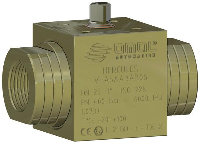
3 1. FOREWORD The present User s Installation and Maintenance Manual has been edited in conformity with: -2014/68/EU Directive Pressure equipment PED -2006/42/EC Directive Machinery -2014/34/EU Directive Equipment and protection systems designated to be used in potentially explosive atmospheres (ATEX) The following standards/technical specifications also apply: - IEC 61508:2010-1/7 Functional safety of electrical/electronic/programmable electronic safety-related systems. Part 1:7 -UNI CEN/TS 764-6:2005 Pressure equipment Part 6: Operating instructions structure and contents. It s up to the reader to find his own product, and the correct operating conditions, possibly referring to the attached drawings. Below you will find the safety instructions, the minimum information for storage / warehousing, the installation, the commissioning, the maintenance and the instructions for disposal of products at the end of their life cycle. OMAL valves are CE marked in accordance with the Directives 2014/68/EU (PED) and/or 2014/34/UE (ATEX). The company disclaims any liability for damage caused by improper use, even if partial, in respect to the information contained in this manual. 2. OPERATION CONDITIONS Every type of valve is described in an accurate way through one or more dedicated drawings. The type of valve, the maximum permitted operating conditions, as well as other important information, are shown in a label or are engraved directly on the valve itself; the appropriate certification (PED, ATEX, API, etc.) is also indicated. The category identification and compliance assessment have been done in conformity with Annex II, table 6 of the PED Directive; this way the most restrictive conditions have also been considered. 3. RISK ASSESSMENT Limits of use OMAL valves are suitable for both indoor and outdoor uses. The technical features of the valves, such as type, size, maximum operating pressure, maximum and minimum operating temperature, flange connection, serial number, are all indicated on the body and/or on the label. Do not use the valves beyond the operating conditions (both the environmental and the performance ones ) or beyond the features stated by manufacturer. The external surface of the valves in carbon steel is not provided with a protective coating but with simple burnishing treatment. It is the end user s responsibility to protect the external surface of the valve against corrosion using a coating that is suitable for the installation environment. Stainless steel valves can be used in corrosive atmospheres or low temperature conditions. In case of special installations (ex. Off shore applications), it is up to the end user to protect the outer surface of the valve from corrosion with a suitable coating. The valves with ATEX configuration, can be installed in areas with potentially explosive atmospheres (EX II 2 GD c TX X). It is recommended to protect the valve from overpressure generated by the use of volatile gases or from possible pressure increase due to overheating (ex. fire)m with appropriate devices, The valves are designed for an on / off type of use and are not safety ones. They must also not be used in an underwater environment and with an external pressure greater than the atmospheric one. Always follow the operating conditions printed on the label or engraved on the valve itself: do not, in any case, exceed such limits as exceeding even one of these limits could lead to dangerous situations and impair the functionality of the valve. Following conditions are the main hazardous ones that have not been eliminated Weather Elements (wind, snow, ice, etc.); Vibrations (resulting from the plant or from the fluid passage); Water hammer (in case of rapid closure of the valve); Corrosion (aggressive atmosphere or not suitably protected valve); Stray current; Shock waves; Uncontrolled chemical reactions. 4. TRASPORTATION AND STORAGE/WEARHOUSING Transportation OMAL valves are properly packaged for an adequate protection during handling and dispatch. Since it cannot be excluded that the product could accidentally get damaged during transportation, it is recommended to carefully check the same upon receipt, before putting it in stock. Verify, therefore, that the packaging, upon reception, is intact, free of damage due to bumps or falls that may have occurred during transportation. Also check that the product that has been received corresponds exactly to what had been requested. The handling of packages on pallets wrapped in shrink wrap barrier, does not require special care; if the package is damaged check if the product has been also damaged, or if there s anything missing. All handling operations must be carried out with suitable means and by qualified personnel. Storage Choose clean sites for storage, not excessively humid and with temperatures between 10 and +60 C. If the products are to be stored for long EN - 3
4 periods of time, it is best not to remove them from their protective packaging. Keep the valves in the package during storage. If the valves are not packaged, then they must be protected by applying plastic caps to the ends, which are usually supplied with the product, in order to avoid liquid or other to penetrate during storage and thus damage the ball or the seals. Should it appear appropriate to apply products for the preservation and protection of the valve, make sure it is dry also on the inside. If the valves are to be stored for long periods of time, then they should be inspected periodically: check in particular the possible presence of rust, oxidation, paint nicks or even partial unscrewing of the closures. It is also recommended to perform a complete dry cycle of opening and closing of the valve. The polymer seals are subject to aging and lose of their characteristics: for this reason, after storage periods of more than two years, it is recommended to check the functionality and the seals before mounting the valve in the line. In the case of flanged valves stored outside, the machined surfaces must be protected with anti-rust varnish and closed with waterproof wood seals, complete with gaskets. 5. INSTALLATION INSTRUCTIONS The design of the valve takes into account the loads arising from the line (axial forces, bending moments, etc.), as required by the reference standards. Check the condition before assembling the valve on the line, making sure that all the parts are intact. Check also the correct operating conditions written on the label or engraved on the valve. Replace any caps on the ends to preserve the valve interior during the handling. If the valve is supplied with a bare stem, carefully follow the installation instructions provided together with the actuator and possible reducer. Such operations must be carried out by an experienced and qualified staff. The use of an actuator allows to open and close the valve connected to it, without manual operations by means of levers or hand-wheels, but through an electro-pneumatic remote command. The normal sizing of the actuators requires to consider an appropriate safety margin in order to guarantee the valve maneuvering. The plant design, physical or chemical features of the fluids, special environmental conditions, may require an increase of the safety factor to be applied to the sizing. Prior to installation verify that the valve and the actuator comply with the above described safety standards. Furthermore, utmost cleanliness is required when connecting the air supply to the actuator. All parts of the plant, reductions, joints, plates, brackets and equipment must be thoroughly cleaned. Before mounting the actuator on the valve be sure that both elements are correctly oriented, depending on the rotation direction needed. Always read the specific instructions carefully before operating the actuator, in order to avoid damage to the valve, the plant and the actuator itself. Handling The valves must be handled by experts and with adequate protection devices. The actuated valves must not be handled through the actuator. For valves weighing less than 25 kg, handling can also be done through manual means. For valves with total weight above 25 kg, the unit must be handled with suitable means (such as slots, eyebolts, etc.). If there aren t any holes or eyebolts you can use the ends, appropriately harnessed, to move the valve. Be careful not to damage the machined surfaces with chains or hooks. Always use approved lifting equipment (hooks, straps, etc.) to bear the weight of the valve and actuator together; this weight is indicated in the shipping documents. In any case avoid handling suspended loads above people, or in places where a possible fall can cause damage. Assembly To prevent damage and protect the valve interior, remove the caps only upon installation. Verify that the inside of the pipe is clean and free of any object or particles that can damage the ball or other parts of the valve. If not otherwise indicated, the valves are bi-directional and can be mounted on either side. In the event that the valve is unidirectional, an arrow will clearly show the flow direction. In this case, make sure that the flow direction coincides with the direction of the arrow. Flanged valves It is totally the installer s responsibility to couple the valve in the line. Place the valve with the ball fully open or fully closed, in order to avoid damage to the sealing surface of the seats and of the ball itself. Verify that the surfaces of the flanges of the valve and the piping are parallel and properly coupled with the seals. Should the exterior painting get damaged during assembly, it is necessary to restore the integrity of the coating. Take special care during assembly, not to let foreign objects of any type or size inside the line, for this could jeopardize the correct and safe operation of the valve and the system itself. Valve with threaded ends Set up proper supports for the pipes in order to avoid that the valves are loaded with weights heavier than the values reported on the following table, even by accident. Valves with threaded ends DN Maximum torque applicable (Nm) Maximum bending moment (Nm) Valves with welded ends Responsibility for the connection between the valve and the line through permanent joint is up to the person installing the valve. During welding, hold the valve in the open position to prevent damage due to thermal expansion, especially the bonding of seats. EN - 4
5 Commissioning The following operations are required before start-up: Inspection and testing of the valve and the line; Flushing Hydraulic test of the line. Inspection and testing of the valve and the line Once the valve is connected in the line, before proceeding to the pressurization of the same, it is necessary to: Check the presence of (any) caps, nipples, drain valves and their correct tightening; Check the tightness of bolts and/or screws between the body/flange and body and lids; Read the instructions and any restrictions regarding the use of the actuator (if any). Flushing The flushing phase is very delicate: if not done properly it may affect the functionality of the valve itself. The cavities of the valve, in fact, can accommodate foreign objects and thus influence its proper functioning. In case fluids carrying abrasive materials are being used, these can be very dangerous, because they can damage the soft seals and the sealing surfaces. The valves with soft seal seats, in fact, are designed to intercept clean fluids, free of solid and abrasive particles. It can be done after completing the installation, cleaning the system with inert gases, vapors or liquids (always checking the compatibility of the fluid that is being used, with the valve), to remove any residue, grease or oil, or foreign objects. Always use fluids that are compatible with the material of the valve and of the seals; especially if the following materials are being used, consider as follows: Amine based corrosion inhibitors may damage the O-ring which is fluorocarbon based; The use of methanol may damage some types of O-rings; Water, especially without inhibitors, may cause the corrosion of carbon steel parts; Fluids containing fluorine and its derivatives can trigger the corrosion of stainless steel parts. Hydraulic line test The hydraulic test of the line should be carried out at a pressure that does not exceed 1.5 times the rating pressure of the valve, indicated on the nameplate or engraved on the body of the valve itself. The test shall be performed with the ball in a half open position so to avoid damaging the seats. If the test is performed on valves that are sealed with polymeric material, keep the ball in a semi open position, during the testing time only and no longer than a few hours. Should it be necessary to test the valve in the closed position, the maximum pressure should not exceed 1.1 times the rating pressure. Once the test is over, depressurize the line and, if possible, vent and discharge the valve. Once the previous operations have been carried out, the valve is ready to be used; if the valve is manually operated (by lever, wheel or reducer), make at least one complete opening and closing maneuver, so to verify its proper functioning. If the valve is actuated, read the instructions carefully, check the pneumatic or electric diagrams and then proceed with a complete opening and closing cycle, so to verify its proper functioning. In order to avoid a functional failure of the valves it is recommended to perform a partial maneuver at least once a year. Shutdown If problems occur on the valve, if possible, close the valves upstream and downstream and shut the pressure to the line. Then perform a complete inspection of the valve so to identify the fault. After a system shutdown, before maneuvering the valve, empty it out (if possible) and drain it as well. Valve removal Before the valve can be removed from the line, it is necessary to: always make sure that the pipeline is not pressurized; actuate the valve by performing an opening/closing cycle so to eliminate any residual pressure trapped inside the body. Never and in any case use vent plugs or drains to drain out the pressure from the valve body; perform accurate flushing cycles with inert fluids or specific corrosion inhibitors, if the valve intercepts substances that are dangerous, corrosive, explosive etc.. and ensure safety measures; use suitable personal protective equipment PPE before opening the valve-pipe connections. After removing the valve from the line, thoroughly clean it and protect the ends by covering them with caps. Inspection The operating conditions can be very different, therefore it is up to the user to establish an adequate inspection interval that is based on the system, the intercepted fluid, operating conditions, etc. Sealing in case of emergency Some valves are equipped with injectors in correspondence with the stem and the seals in order to seal the valve if needed (usually to stop a leak). Before proceeding with the sealing operation, make sure the sealer is compatible with the materials of the valve and the intercepted fluid, so EN - 5
6 to avoid dangerous chemical reactions that could cause harm to people, the environment and to the system. The flushing fluids and sealers can be pumped in by a manual or pneumatic pump, checking that the nominal pressure of the pump and accessories is higher than the rating pressure of the valve. 6. MAINTENANCE The efficiency of the product is the result of a good and careful maintenance; check the system efficiency status at least once a year, providing immediate replacement of worn parts, in case leaks are found, both in the ducts and on the outside of the valves. Normally, for medium duty applications, the replacement time of parts subject to wear for the various types of valves is summarized in the table below. Maintenance operations must be performed by qualified personnel. DN DN DN DN N cycles PN < N cycles PN > DN 6-10 DN DN N cycles PN > DISPOSAL OF PRODUCTS AT THE END OF THEIR LIFE CYCLE Once that the valve has reached the end of its operating life, it can be removed from the system by following the procedures that are suitable to the type of valve and to the operating conditions. If the valve intercepts toxic, corrosive and/or hazardous substances, it must first be cleared by an appropriate flushing cycle and the waste is to be disposed of according to the applicable regulations. Once removed from the system, protect the ends and all the possible openings (valve drains, nipples, etc.) through an appropriate sealing system, in order to prevent the dispersion and the contact by any pollutants or hazardous materials, left inside the valve. In case a fluid leakage from inside the valve occurs, it is required to act promptly, decontaminate and secure the contaminated environment, as required by the relevant laws and regulations. The personnel in charge of the product disposal/recovery, must be qualified and equipped with appropriate personal protective equipment (PPE), according to the type of fluid intercepted (polluting, corrosive, etc.). Once disassembled and secured, bring the valve to a site that is designated as the storage site and that complies with the requirements of the European national, regional and municipal environmental and safety standards. The management of waste generated during the installation, extraordinary maintenance or due to the product disposal, is governed by the rules in force in the country where the product is installed; in any case, the following are the general guidelines: - The metal components (aluminum/steel) can be restored as raw material; - Seals/sealing elements (PTFE, PEEK, NBR, EPDM, FKM...), as contaminated by fluids from other materials and lubrication, must be disposed of; - The packaging materials that come with the product, should be transferred to the differentiated collection system available in the country. 8. SPARE PARTS Use only original spare parts, for maintenance; always mention, when ordering the spare parts, the part number and date of manufacture stamped on the valve, to be sure to receive spare parts that are compatible with the product in the most recent version possible. For detailed information on the mounting and dismounting, refer to the specific instructions for each type of valve. EN - 6
7 9. TROUBLESHOOTING You can find main failures with possible causes and possible solutions listed here below: FAILURE POTENTIAL CONSEQUENCES POTENTIAL FAILURES SOLUTION Ball incomplete closure Check the manoeuvring system Worn seats/ ball Replace worn parts and carry on maintenance as per manual / instructions Valve leakage on the line provided Chemical incompatibility with valve building materials or incorrect use (operating conditions exceed the ones established for the project) Damage on the stem seat Replace worn parts and carry on Damage on static seats (body seal / terminal-ring & body / lids, if present) maintenance as per manual / instructions provided Leakage on the outside Chemical incompatibility with valve building materials or incorrect use (operating conditions exceed the ones established for the project) Driving system fault Possible ball / stem gripping Blocked valve Increase in maneuvering time / shooting motion Insufficient rotation angle Accumulation of solid particulate in the cavities of the body Stem break Actuator- valve connection s break Possible ball / stem gripping Possible partial actuator gripping Actuator cannot perform the maneuver Insufficient air supply to produce the required torque Mechanical stop (if present) not properly adjusted Possible ball / stem gripping Incorrect fixing between actuator outlet hole and valve stem Replace worn parts and carry on maintenance as per manual / instructions provided Check actuator dimensioning and verify that actuator fluid pressure is equal to or greater than nominal pressure on plate Adjust the stroke limiters Check for proper connecting kit between valve and actuator 10. STATEMENT OF CONFORMITY OMAL ball valves have been designed, manufactured and tested to meet the requirements of the following European standards and are marked, where provided, with the relative CE conformity marking: 2014/68/EU Directive Pressure equipment PED 2006/42/EC Directive Machinery 2014/34/EU Directive Equipment and protective systems intended for use in potentially explosive atmospheres (ATEX) Regulation (EC) No 1907/2006 and successive Concerning the Registration, Evaluation, Authorization and Restriction of Chemicals (REACH) EN - 7
KTM OM-2 SPLIT BODY FLOATING BALL VALVES INSTALLATION AND MAINTENANCE INSTRUCTIONS
 Before installation these instructions must be fully read and understood SECTION 1 - STORAGE 1.1 Preparation and preservation for storage All valves should be properly packed in order to protect the parts
Mounting and Operating Instructions EB 3007 EN. Self-operated Pressure Regulators. Differential Pressure Regulators (opening) Type Type 42-25
 Type Type 42-25") Self-operated Pressure Regulators Differential Pressure Regulators (opening) Type 42-20 Type 42-25 Type 42-20 Differential Pressure Regulator Type 42-25 Differential Pressure Regulator Mounting and Operating
Self-operated Pressure Regulators Differential Pressure Regulators (opening) Type 42-20 Type 42-25 Type 42-20 Differential Pressure Regulator Type 42-25 Differential Pressure Regulator Mounting and Operating
Installation & Operation Manual Proven Quality since 1892
 Content 1. ERIKS operating companies 2. Product description 3. Requirements for maintenance staff 4. Transport and storage 5. Function 6. Application 7. Installation 8. Maintenance 9. Service and repair
OPERATING MANUAL. Contents. Bottom outlet ball valve Type ecoline
 OPERATING MANUAL Bottom outlet ball valve Type ecoline Contents 1 General Information 2 Safety 3 Packing, Handling, Storing 4 Product description 5 Preparation, Assembly 6 Commissioning 7 Handling 8 Attendance
CAST IRON SAFETY VALVE TYPE 6301
 CHARACTERISTICS The 6301 safety valve is dedicated to protect the equipment from potential overpressure. This is an automatic device that closes when the pressure conditions are back to normal. It is a
Mounting and Operating Instructions EB 2558 EN. Self-operated Pressure Regulators. Type Pressure Build-up Regulator
 Self-operated Pressure Regulators Type 2357-31 Pressure Build-up Regulator with safety function and integrated excess pressure valve Type 2357-31 with non-return unit at port C Ports A and B with soldering
Spilt body Flange ball valve. TC-205MFF-PN1640 User Manual English Version. Document No: TC-205MFF-PN1640.Ur-manual. Date: 2007/04/2617. Version: 1.
 Spilt body Flange ball valve TC-205MFF-PN1640 Series PED Category I,II TC-205MFF-PN1640 User Manual English Version Use for company in Europe who will place the product on the market, please amend which
Manual Actuated Boiler Blowdown Valves
 Manual Actuated Boiler Blowdown Valves Installation and Maintenance Instructions 1. Safety information 2. General product information 3. Installation 4. Operation 5. Maintenance 6. Spare parts p.1 1. Safety
INSTRUCTIONS AND MAINTENANCE MANUAL SERIES: RT
 INSTRUCTIONS AND MAINTENANCE MANUAL 05/11/2015 SERIES: RT cmo @cmo.es http://www.cmo.es page 1 ASSEMBLY THE RT VALVE COMPLIES WITH THE FOLLOWING: Machinery Directive: DIR 2006/42/EC (MACHINERY) Pressure
Differential Pressure Regulator Type Type 45-6 (0.1 to 1 bar, DN 15) Mounting and Operating Instructions EB 3226 EN
 Mounting and Operating Instructions EB 3226 EN") Differential Pressure Regulator Type 45-6 Type 45-6 (0.1 to 1 bar, DN 15) Mounting and Operating Instructions EB 3226 EN Edition March 2008 Contents Contents Page 1 Design and principle of operation...................
Differential Pressure Regulator Type 45-6 Type 45-6 (0.1 to 1 bar, DN 15) Mounting and Operating Instructions EB 3226 EN Edition March 2008 Contents Contents Page 1 Design and principle of operation...................
Installation, Operating and Maintenance Instructions. V914 Cast Iron Flanged Swing Check Valve V914
 Installation, Operating and Maintenance Instructions V914 Cast Iron Flanged Swing Check Valve V914 THE PRESSURE EQUIPMENT DIRECTIVE 97/23/EC and CE MARKING The Pressure Equipment Regulations 1999 (SI 1999/2001)
INSTALLATION COMMISSIONING, OPERATION & MAINTENANCE MANUAL
 WedgeRock RW Series Worm Gear Actuators INSTALLATION COMMISSIONING, OPERATION & MAINTENANCE MANUAL Revision 01 Date 4/3/17 Page 1 Table of Contents 1.0 INTRODUCTION... 4 1.1 PURPOSE... 4 1.2 AUDIENCE...
Engineering Data Sheet
 Page 1 of 6 CE MARKING AND THE PRESSURE EQUIPMENT DIRECTIVE 97/23/EC Valves must be installed into a well designed system and it is recommended that the system be inspected in accordance with the appropriate
Apollo Standard Port, Full Port & One Piece Flanged Ball Valves Installation, Operation, & Maintenance Manual
 I854000.D Apollo Standard Port, Full Port & One Piece Flanged Ball Valves Installation, Operation, & Maintenance Manual Introduction This manual presents guidelines for the Installation, Operation and
KBV21i and KBV40i Key Operated Boiler Blowdown Valves Installation and Maintenance Instructions
 4059051/3 IM-P405-48 EMM Issue 3 KBV21i and KBV40i Key Operated Boiler Blowdown Valves Installation and Maintenance Instructions 1. Safety information 2. General product information 3. Installation 4.
Declaration of Conformity as per Directive 97/23/EC
 Declaration of Conformity as per Directive 97/23/EC The manufacturer declares that:, 47906 Kempen, Germany Multi-way diverting valves Series 29a and Series 29b, with packing with lever 1. The valves are
Installation, Operation and Maintenance Manual for Back Pressure Regulator
 Installation, Operation and Maintenance Manual for Back Pressure Regulator Model 8860 2009 Groth Corporation IOM-8860 Rev. B 12541 Ref. ID: 95565 Page 2 of 13 Table of Contents I. INTRODUCTION 3 II. DESIGN
THE BP-301 SERIES. Operating and Service Manual. Series includes all variants of BP-301 (LF 0.1Cv / MF 0.5Cv)
") THE BP-301 SERIES Operating and Service Manual Series includes all variants of BP-301 (LF 0.1Cv / MF 0.5Cv) Issue B October 2015 1 TABLE OF CONTENTS 1. Description... 3 2. Installation... 3 3. Operation...
THE BP-301 SERIES Operating and Service Manual Series includes all variants of BP-301 (LF 0.1Cv / MF 0.5Cv) Issue B October 2015 1 TABLE OF CONTENTS 1. Description... 3 2. Installation... 3 3. Operation...
MODEL 200 KNIFE GATE VALVES INSTALLATION & MAINTENANCE MANUAL
 MODEL 200 KNIFE GATE VALVES INSTALLATION & MAINTENANCE MANUAL Index 1. List of components / General arrangement 2. Description 3. Handling 4. Installation 5. Actuators / Operation 6. Maintenance a. Changing
INSTRUCTIONS AND MAINTENANCE MANUAL SERIES: K
 INSTRUCTIONS AND MAINTENANCE MANUAL 05/09/2014 SERIES: K cmo@cmo.es http://www.cmo.es Page 1 ASSEMBLY DESCRIPTION Machinery Directive: DIR 2006/42/EC (MACHINERY) Pressure Equipment Directive: DIR 97/23/EC
Declaration of Conformity as per Directive 97/23/EC
 Declaration of Conformity as per Directive 97/23/EC The manufacturer declares that:, 47906 Kempen, Germany Continuous, inline sampling valves Series 27f, with packing Operate with either; Star lever, or
Operating instruction
 Operating instruction MV, XV, HG, HP, RKO, D2G, TV, BV, WB & SLV 1 Introduction 2 2 Stafsjö s knife gate valves 2 3 Technical information 2 3.1 Pressure test 2 3.2 Labelling 2 4 Storage 3 5 Transportation
Mounting and Operating Instructions EB 3007 EN. Self-operated Pressure Regulators. Type Type Differential Pressure Regulators (opening)
") Self-operated Pressure Regulators Type 42-20 Type 42-25 Differential Pressure Regulators (opening) Translation of original instructions Type 42-20 Differential Pressure Regulator Type 42-25 Differential
Self-operated Pressure Regulators Type 42-20 Type 42-25 Differential Pressure Regulators (opening) Translation of original instructions Type 42-20 Differential Pressure Regulator Type 42-25 Differential
WKM Model 320F Floating Ball Valve
 Date: 4 WKM Model 320F Floating Ball Valve Installation, Operation, and Maintenance Manual 1 Date: 4 All the information contained in this manual is the exclusive property of Cameron. Any reproduction
1. Preface Important Safety Notes Brief Product Information Product Working Principle Installation Guidelines...
 Table of Contents 1. Preface...1 2. Important Safety Notes...1 3. Brief Product Information...3 4. Product Working Principle...5 5. Installation Guidelines...6 6. Startup and Commissioning...8 7. Maintenance
Type 2000 INOX. Quickstart. English Deutsch Français. 2/2-way angle seat valve 2/2-Wege Schrägsitzventil Vanne à siège incliné 2/2 voies
 Type 2000 INOX 2/2-way angle seat valve 2/2-Wege Schrägsitzventil Vanne à siège incliné 2/2 voies Quickstart English Deutsch Français Contents 1 QUICKSTART... 2 2 CONTACT ADDRESS... 2 3 INTENDED USE...
INSTALLATION, OPERATION AND MAINTENANCE INSTRUCTIONS TYPE BV2-LD
 INSTALLATION, OPERATION AND MAINTENANCE INSTRUCTIONS TYPE BV2-LD 1. Storage & Protection 1.1. Storage The valves stay in the open position during the transportation. For incoming QC must check: a. Packing
3-PIECE BALL VALVE, 3600 PSI/ PN 248, WITH ISO DIRECT MOUNTING PAD 306M SERIES/ PED Category II
 3-PIECE BALL VALVE, 3600 PSI/ PN 248, WITH ISO DIRECT MOUNTING PAD 306M SERIES/ PED Category II 306M User Manual English Version Use for company in Europe who will place the product on the market, please
FLANGED TWO-PIECE BALL VALVES
 INTRODUCTION This instruction manual includes installation, operation, and maintenance information for FNW flanged split-body ball valves. This manual addresses lever operated ball valves only. Please
SAPAG. Safety valves, type 5700 Storage, Use, Operation and Maintenance Instructions. IMPORTANT NOTICE
 SAPAG IMPORTANT NOTICE Contents Important notice 1 0 Valve identification 2 1 Storage 2 2 Installation 2 3 Operation 2 4 Maintenance 3 4.1 Dismantling 3 4.2 Inspection 3 4.3 Repair 3 4.4 Assembly 4 4.5
CARTRIDGE FILTERS TECHNICAL MANUAL MT 080. Installation, commissioning and maintenance instructions. 08/02 Edition
 CARTRIDGE FILTERS TECHNICAL MANUAL MT 080 Installation, commissioning and maintenance instructions 08/02 Edition 1 2 CONTENTS 1.0 PAGE INTRODUCTION 1.1 MAIN FEATURES 1.2 OPERATION 1.3 CLOSING OF HEAD WITH
Mounting and operating instructions EB 2530 EN. Self-operated Pressure Regulator. Pressure Reducing Valve Type M 44-2
 Self-operated Pressure Regulator Pressure Reducing Valve Type M 44-2 Type M 44-2, connection G 1 4, K VS = 0.15 Type M 44-2, connection G 1, K VS = 6 Fig. 1 Type M 44-2 Pressure Reducing Valve Mounting
ITT RICHTER CHEMIE-TECHNIK
 ITT RICHTER CHEMIE-TECHNIK The Answer to Corrosion Series MV/MVP Operating Manual for Diaphragm Valves Contents 1 General 2 Safety 3 Transport and storage 4 Product description 5 Installation 6 Operation
VALFONTA INSTRUCTIONS: OPERATION AND INSTALLATION PRESSURE REDUCING VALVE MODEL PRV44
 INSTRUCTIONS: OPERATION AND INSTALLATION PRESSURE REDUCING VALVE MODEL PRV44 Pressure Reducing Valve PRV44 - Operation and Installation - 1 - manual PRV44-16-ENG JULY 2016 INDEX PAGE 1 IDENTIFICATION PLATE
KBV21i and KBV40i Air Actuated Boiler Blowdown Valves
 4059051/1 IM-P405-48 AB Issue 1 KBV21i and KBV40i Air Actuated Boiler Blowdown Valves Installation and Maintenance Instructions 1. Safety information 2. General product information 3. Installation 4. Commissioning
FLANGED TWO-PIECE BALL VALVES
 INTRODUCTION This instruction manual includes installation, operation, and maintenance information for FNW flanged split-body ball valves. This manual addresses lever operated ball valves only. Please
6301 TYPE CAST IRON SAFETY VALVES
 Pressure (bar) 6301 TYPE CAST IRON SAFETY VALVES FEATURES The 6301 type safety valve is a device designed to protect installations against possible overpressure. It operates automatically and closes when
Type 3709 Pneumatic Lock-up Valve. Translation of original instructions. Mounting and Operating Instructions EB 8391 EN
 Type 3709 Pneumatic Lock-up Valve Translation of original instructions Mounting and Operating Instructions EB 8391 EN Edition July 2017 Note on these mounting and operating instructions These mounting
Instructions for Installation, Operating and Maintenance
 Instructions for Installation, Operating and Maintenance for ABO butterfly valves series 500 1) Introduction 2) Safety Instructions 3) Valve Identification 4) Transportation and Storage 5) Installation
Telefon (+45) Telefax (+45)
 Telefax (+45)") Uni-Valve A /S VENTILER & INSTRUMENTER Telefon (+45) 43 43 82 00 Telefax (+45) 43 43 74 75 mail@uni-valve.com www.uni-valve.com UNI-S83 / S84 3/4-way ball valve Installation and Operating manual 3/4-WAY
Uni-Valve A /S VENTILER & INSTRUMENTER Telefon (+45) 43 43 82 00 Telefax (+45) 43 43 74 75 mail@uni-valve.com www.uni-valve.com UNI-S83 / S84 3/4-way ball valve Installation and Operating manual 3/4-WAY
Declaration of Conformity as per Directive 97/23/EC
 Declaration of Conformity as per Directive 97/23/EC The manufacturer declares that:, 47906 Kempen, Germany Discontinous, inline sampling valves Series 27a and Series 27g, with packing with lever (180 )
G type DUCTED EXHAUST SAFETY VALVE 2871 AND 288X SERIES. Model/Ref:
 Model/Ref: 28713 www.lauridsenindustri.com CHARACTERISTICS The G type safety valves are dedicated to protect the equipment from potential overpressure. They are automatic and close when the pressure conditions
PV4 and PV6 Piston Valves
 1181250/1 IM-P118-05 ST Issue 1 PV4 and PV6 Piston Valves Installation and Maintenance Instructions 1. Safety information 2. General product information 3. Installation 4. Commissioning 5. Operation 6.
Type BBS-03, BBS-05, BBS-06, BBS-25
 Type BBS-03, BBS-05, BBS-06, BBS-25 Sterile connection elements Sterile Verbindungselemente Raccords union stériles Operating Instructions Bedienungsanleitung Manuel d utilisation 1. THE OPERATING INSTRUCTIONS
English. Introduction. Safety Instructions. All Products. Inspection and Maintenance Schedules. Parts Ordering. Specifications WARNING WARNING
 Contents All Products... Gb-1 Control Valves... Gb-2 Control Valve Actuators... Gb-3 Regulators... Gb-3 Relief Valves... Gb-4 Instruments, Switches, and Accessories... Gb-4 Products Covered by Battery
S1, S2, S3, S5, S6, S7, S8, S12 and S13 Separators Installation and Maintenance Instructions
 PREVIOUS REFERENCE NO. IMP02355 0231150/13 IMF0501ENISS2 CMGT S1, S2, S3, S5, S6, S7, S8, S12 and S13 Separators Installation and Maintenance Instructions 1. Safety information 2. General product information
Installation, operation & maintenance manual - original version
 Installation, operation & maintenance manual - original version AVK gate valves for water and wastewater Series 01, 02, 06, 12, 15, 18, 20, 26, 32, 33, 36, 38, 50, 55 and 636 COPYRIGHT AVK GROUP A/S 2018
Steam Trap BK 15 (DN40, DN 50) Original Installation Instructions English
 Original Installation Instructions English") Steam Trap BK 15 (DN40, DN 50) EN English Original Installation Instructions 810682-03 1 Contents Page Important Notes Usage for the intended purpose... 4 Safety note... 4 Danger... 4 Attention... 4 Application
Steam Trap BK 15 (DN40, DN 50) EN English Original Installation Instructions 810682-03 1 Contents Page Important Notes Usage for the intended purpose... 4 Safety note... 4 Danger... 4 Attention... 4 Application
HM and HM34 Inverted Bucket Steam Traps Installation and Maintenance Instructions
 0670350/4 IM-S03-11 ST Issue 4 HM and HM34 Inverted Bucket Steam Traps Installation and Maintenance Instructions 1. Safety information 2. General product information HM Series 3. Installation 4. Commissioning
USM21 Sealed Bimetallic Steam Trap for use with Pipeline Connectors Installation and Maintenance Instructions
 6250250/1 IM-P625-03 ST Issue 1 USM21 Sealed Bimetallic Steam Trap for use with Pipeline Connectors Installation and Maintenance Instructions 1. General safety information 2. General product information
THE HF-300 SERIES. Operating and Service Manual. Series includes all variants of HF-300/301
 THE HF-300 SERIES Operating and Service Manual Series includes all variants of HF-300/301 Issue A July 2015 1 TABLE OF CONTENTS 1. Description... 3 2. Installation... 3 3. Operation... 4 3.1. Spring Loaded...
INSTALLATION, MAINTENANCE & OPERATING INSTRUCTIONS 2-4 REDUCED PORT/ FULL PORT (5700/6700) ANSI CLASS 150/300/600/900/1500/2500 TRUNNION BALL VALVES
 ANSI CLASS 150/300/600/900/1500/2500 TRUNNION BALL VALVES") PBV-USA,Inc. 12735 Dairy Ashford. Stafford, Texas USA 77477 281-340-5400; 800-256-6193 FAX: 281-340-5499 INDUSTRIAL BALL VALVES IM0 69 April 2001 Rev 9 INSTALLATION, MAINTENANCE & OPERATING INSTRUCTIONS
PBV-USA,Inc. 12735 Dairy Ashford. Stafford, Texas USA 77477 281-340-5400; 800-256-6193 FAX: 281-340-5499 INDUSTRIAL BALL VALVES IM0 69 April 2001 Rev 9 INSTALLATION, MAINTENANCE & OPERATING INSTRUCTIONS
INSTRUCTIONS AND MAINTENANCE MANUAL SERIES: FK
 INSTRUCTIONS AND MAINTENANCE MANUAL 04/09/2014 SERIES: FK cmo@cmo.es http://www.cmo.es Page 1 ASSEMBLY THE FK VALVE COMPLIES WITH THE FOLLOWING: Machinery Directive: DIR 2006/42/EC (MACHINERY) Pressure
SRV66 Sanitary Pressure Reducing Valve
 1866350/4 IM-P186-09 CH Issue 4 SRV66 Sanitary Pressure Reducing Valve Installation and Maintenance Instructions 1. Safety information 2. General product information 3. Installation 4. Operation 5. Commissioning
ANNEX AMENDMENTS TO THE INTERNATIONAL CODE FOR FIRE SAFETY SYSTEMS (FSS CODE) CHAPTER 15 INERT GAS SYSTEMS
 CHAPTER 15 INERT GAS SYSTEMS") Annex 3, page 2 ANNEX AMENDMENTS TO THE INTERNATIONAL CODE FOR FIRE SAFETY SYSTEMS (FSS CODE) CHAPTER 15 INERT GAS SYSTEMS The text of existing chapter 15 is replaced by the following: "1 Application This
Annex 3, page 2 ANNEX AMENDMENTS TO THE INTERNATIONAL CODE FOR FIRE SAFETY SYSTEMS (FSS CODE) CHAPTER 15 INERT GAS SYSTEMS The text of existing chapter 15 is replaced by the following: "1 Application This
BSA6T and BSA64T Stainless Steel Bellows Sealed Stop Valves Installation and Maintenance Instructions
 1843950/3 IM-P184-03 ST Issue 3 BSA6T and BSA64T Stainless Steel Bellows Sealed Stop Valves Installation and Maintenance Instructions 1. General safety information 2. General product information 3. Installation
Ball valve. Operating instructions for series. Version BA Print-No TR MA DE Rev001
 Ball valve Operating instructions for series Version BA-2016.02.05 Print-No. 300 587 TR MA DE Rev001 We reserve the right to make technical changes. Read carefully before use. Save for future use. ASV
Spiratec ST14, ST16 and ST17 Sensor Chambers and sensors
 0862050/1 IM-P086-18 MI Issue 1 Spiratec ST14, ST16 and ST17 Sensor Chambers and sensors Installation and Maintenance Instructions 1. Safety Information 2. General product information 3. Installation 4.
Cast iron swing check valve. BS EN 12334:2001 PN16
 Cast iron swing check valve. BS EN 12334:2001 PN16 V914 Size Pattern No. Pack 1 Qty Pack 2 Qty Code Barcode Price ( ) ex VAT 65mm V914 1 0 15378 5022050079664 223.32 80mm V914 1 0 15379 5022050079824 247.60
VS18/26 with PROFINET and EtherNet/IP Interface. ATEX Installation Instructions
 VS18/26 with PROFINET and EtherNet/IP Interface ATEX Installation Instructions INDEX 1. INTENDED USAGE 3 2. OPERATING MANUAL ATEX 4 2.1 General conditions 4 2.2 Installation 5 2.3 Operating 5 2.4 Failures
Pressure relief valve
 Pressure relief valve Operating manual Series DHV 718 Version BA-2016.01.11 EN Print-No. 300 524 TR MA DE Rev001 ASV Stübbe GmbH & Co. KG Hollwieser Straße 5 32602 Vlotho Germany Phone: +49 (0) 5733-799-0
FLANGED MULTI-PORT BALL VALVES
 INTRODUCTION This instruction manual includes installation, operation and maintenance information for flanged multi-port ball valves. This manual addresses lever operated ball valves only. Please refer
THE BP-690 SERIES. Operating and Service Manual. Series includes all variants of BP-LF/MF-690/691
 THE BP-690 SERIES Operating and Service Manual Series includes all variants of BP-LF/MF-690/691 Issue B April 2015 1 TABLE OF CONTENTS 1. Description... 3 2. Installation... 3 3. Operation... 4 4. Special
Contents. 1. General information BROEN BALLOMAX Steel Ball Valves Approvals Quality Management...2
 Contents 1. General information...2 1.1 BROEN BALLOMAX Steel Ball Valves...2 1.2 Approvals...2 1.3 Quality Management...2 2. Preoperational Instructions and Precautions...2 3. Plates...3 4. Transport and
OPERATING AND MAINTENANCE MANUAL ALFA WAFER BALL VALVES Models ALFA 10N / 10NF / 103 / 10HP
 Sheet 1 of 9 ALFA WAFER BALL VALVES Models ALFA 10N / 10NF / 103 / 10HP INDEX PAGE 0. Technical Data 2 1. Transportation, handling and storage 3 2. Installation instructions 3 3. Maintenance 5 4. Testing
Type /2-Way Globe Valve 3/2-Wege-Geradsitzventil Vanne à siège droit 3/2 voies Operating Instructions Bedienungsanleitung Manuel d utilisation
 3/2-Way Globe Valve 3/2-Wege-Geradsitzventil Vanne à siège droit 3/2 voies Operating Instructions Bedienungsanleitung Manuel d utilisation We reserve the right to make technical changes without notice.
Declaration of Conformity as per Directive 97/23/EC and Manufacturer s Declaration as per Directive 98/37/EC
 Declaration of Conformity as per Directive 97/23/EC and Manufacturer s Declaration as per Directive 98/37/EC The manufacturer declares that:, 47906 Kempen, Germany Continuous, PFA-lined, inline sampling
Pressure Equipment Directive (PED) 97/23/EC Page 033 of 124
 97/23/EC Page 033 of 124") Pressure Equipment Directive (PED) 97/23/EC Page 033 of 124 13.7 Pressure Equipment Directive (PED) 97/23/EC 1 The Pressure Equipment Directive (PED) 97/23/EC applies to the design, manufacturing and conformity
Pressure Equipment Directive (PED) 97/23/EC Page 033 of 124 13.7 Pressure Equipment Directive (PED) 97/23/EC 1 The Pressure Equipment Directive (PED) 97/23/EC applies to the design, manufacturing and conformity
Serie 06-M6. Swing wafer check valve. made in. Application fields. Check valves E U R O P E WATER CONDITIONING INDUSTRY
 Swing wafer check valve BRANDONI made in E U R O P E Application fields WATER CONDITIONING INDUSTRY HEATING 38 www.brandoni.it The valves in series 06 are swing wafer check valves, manufactured in accordance
THE MF-400 SERIES. Operating and Service Manual. Series includes all variants of MF-400/401
 THE MF-400 SERIES Operating and Service Manual Series includes all variants of MF-400/401 Issue A October 2013 1 TABLE OF CONTENTS 1. Description... 3 2. Installation... 3 3. Operation... 4 4. Special
Steam trap BK 37 BK 28 BK 29 BK 37 ASME BK 28 ASME BK 29 ASME
 Steam trap BK 37 BK 28 BK 29 BK 37 ASME BK 28 ASME BK 29 ASME Original Installation Instructions 818689-05 Contents Foreword... 3 Availability... 3 Formatting features in the document... 3 Safety... 3
INSTRUCTIONS FOR THE INSTALLATION, COMMISSIONING AND MAINTENANCE
 BALL VALVE FULLY WELDED TECHNICAL MANUAL INSTRUCTIONS FOR THE INSTALLATION, COMMISSIONING AND MAINTENANCE MT 040/E 1 Edition 01/10/15 rev.02 TABLE OF CONTENTS 1.0 INTRODUCTION 1.1 MAIN SPECIFICATIONS 1.2
User guide DIAPHRAGM SEALS. Industrial instrumentation for Pressure and Temperature
 Industrial instrumentation for Pressure and Temperature ENG MI-SEP-ENG_0 10/2011 Copyright Nuova Fima S.p.A. All rights reserved. Any part of this publication should not be reproduced without a written
USER MANUAL. 1. Principle of operation. 2. Delivery condition. SPRING-LOADED SAFETY VALVES zarmak. Edition: 07/2016 Date: V (ex.
 ZETKAMA Sp. z o.o. ul. 3 Maja 12 PL 57-410 Ścinawka Średnia SPRING-LOADED SAFETY VALVES zarmak USER MANUAL 782V (ex. 782) Edition: 07/2016 Date: 01.07.2016 TABLE OF CONTENTS 1. Principle of operation 2.
KTM 50 (DN ) Installation, maintenance and operating instructions
 Installation, maintenance and operating instructions") 52 762-306 09.2014 KTM 50 (DN 100-200) Installation, maintenance and operating instructions General High-performing and compact, these pressure-independent control valves for variable flow heating and
52 762-306 09.2014 KTM 50 (DN 100-200) Installation, maintenance and operating instructions General High-performing and compact, these pressure-independent control valves for variable flow heating and
Wafer Check Valve. Contents. User s Manual. (1) Be sure to read the following description of our product warranty 1
 Be sure to read the following description of our product warranty 1") Serial No. H-V066-E-3 Wafer Check Valve User s Manual Contents (1) Be sure to read the following description of our product warranty 1 (2) General operating instructions 2 (3) General instructions for
Serial No. H-V066-E-3 Wafer Check Valve User s Manual Contents (1) Be sure to read the following description of our product warranty 1 (2) General operating instructions 2 (3) General instructions for
Steam Trap BK BK 212-ASME. Original Installation Instructions English
 Steam Trap BK 212.. BK 212-ASME EN English Original Installation Instructions 810609-02 1 Contents Page Important Notes Usage for the intended purpose... 3 Safety note... 3 Danger... 3 Attention... 3 Application
Mooney * Noise Controller Installation, Operation, and Maintenance Manual
 GE Oil & Gas Mooney * Noise Controller Installation, Operation, and Maintenance Manual imagination at work Scope This manual provides instructions for installation, operation and maintenance of the Mooney
Sempell High Pressure Forged Check Valves Forged steel, swing check and tilting disc configuration
 Installation and Maintenance Instructions Handling requirements A - Packed valves Pallets: Lifting and handling of the packed valves in pallets will be carried out by a fork lift truck, by means of the
KTM V-PORT CONTROL BALL VALVES INSTALLATION AND OPERATION MANUAL
 Please read through this manual completely before operating the valves SECTION 2 - SPECIFICATIONS The safety of the valves and conformity with your equipment should be checked by the design engineer or
USER INSTRUCTIONS. NAF Duball DL Ball Valves. Installation Operation Maintenance. Experience In Motion. flowserve.com
 USER INSTRUCTIONS NAF Duball DL Ball Valves FCD NFENIM4167-01-A4 01/17 Installation Operation Maintenance 1 Experience In Motion Contents SAFETY 3 1 General 3 2 Lifting 4 3 Receiving Inspection 4 4 Installation
Inverted Bucket Steam Trap IB 16A-7
 Inverted Bucket Steam Trap IB 16A-7 Original Installation Instructions 819114-02 Contents Preface... 3 Availability... 3 Text layout... 3 Safety... 3 Usage for the intended purpose... 3 Basic safety notes...
Neotecha SAPRO - Aseptic sampling valve SV Installation, operation and maintenance instructions
 Before installation these instructions must be fully read and understood 2 Safety Please read these instructions carefully. 2.1 General danger potential Not paying attention to this instruction Incautious
MSC-P and MSC-N Manifolds for Steam Distribution and Condensate Collection
 1170850/1 IM-P117-36 ST Issue 1 MSC-P and MSC-N Manifolds for Steam Distribution and Condensate Collection Installation and Maintenance Instructions 1. Safety information 2. General product information
TECHNICAL DATA MAINTENANCE AIR COMPRESSOR MODEL G-1
 Dry 131h 1. DESCRIPTION The Viking Model G-1 Maintenance Air Compressor is an electric motor-driven, aircooled, single-stage, oil-less compressor. The unit is equipped with a check valve and provides a
Mounting and Operating Instructions EB 2172 EN. Series 43 Temperature Regulators. Type 43-5 and Type Type Type 43-6
 Series 43 Temperature Regulators Type 43-5 and Type 43-7 Type 43-6 Type 43-6 Type 43-7 with flanged valve body, DN 32 to 50 Type 43-5 Type 43-7 with welding ends Mounting and Operating Instructions EB
Un-Pressurized Orefice Fittings FIO EZ. Parts List and Operation Instructions TECHNICAL MANUAL. Dn 2-6 Class Lbs
 Un-Pressurized Orefice Fittings FIO EZ Parts List and Operation Instructions TECHNICAL MANUAL Dn 2-6 Class 150-600 Lbs US US 2 FIO EZ - MT 108-US - 05-2016 FIO EZ Important Instructions US Pietro Fiorentini
Pressure relief valve
 Pressure relief valve Operating manual Series DHV 712 R Version BA-2016.01.19 EN Print-No. 300 472 TR MA DE Rev001 ASV Stübbe GmbH & Co. KG Hollwieser Straße 5 32602 Vlotho Germany Phone: +49 (0) 5733-799-0
Installation, Operation and Maintenance Instructions Buffer Vessel OM006
 Installation, Operation and Maintenance Instructions Buffer Vessel OM006 Calorifiers Heat Exchangers Pressurisation Units Sales Tel: 01457 835700 Sales Fax: 01457 832700 E-mail: sales@gmsthermal.co.uk
OPERATING AND MAINTENANCE MANUAL ALFA SPLIT BODY TRUNNION MOUNTED BALL VALVES Model ALFA T2 (Valid for S.B. valves both for D.B.B.
 Doc. Nr. MMT2 Rev.9 EN Sheet 1 of 14 ALFA Model ALFA T2 (Valid for S.B. valves both for D.B.B. valves) INDEX PAGE 0. Technical Data 2 1. Transportation, handling and storage 3 2. Installation instructions
DelVal Flow Controls Private limited
 DelVal Flow Controls Private limited (A DIVISION OF DelTech CONTROLS LLC, USA) DelVal Series 50/5, 5A/5B Butterfly Valves INSTALLATION, OPERATION AND MAINTENANCE MANUAL ENGINEERING DATA SHEET E.D.S. NO
VALFONTA INSTRUCTIONS: OPERATION AND INSTALLATION PRESSURE REDUCING VALVE MODEL M2
 INSTRUCTIONS: OPERATION AND INSTALLATION PRESSURE REDUCING VALVE MODEL M2 Pressure Reducing Valve M2 - Operation and Installation - 1 - M2-13E-ENG FEBRUARY 2017 ÍNDICE PÁGINA 1 IDENTIFICATION PLATE LEGEND
RS(H)10,15 USER MANUAL. Read the complete manual before installing and using the regulator.
10,15 USER MANUAL. Read the complete manual before installing and using the regulator.") RS(H)10,15 USER MANUAL Read the complete manual before installing and using the regulator. WARNING INCORRECT OR IMPROPER USE OF THIS PRODUCT CAN CAUSE SERIOUS PERSONAL INJURY AND PROPERTY DAMAGE. Due to
RS(H)10,15 USER MANUAL Read the complete manual before installing and using the regulator. WARNING INCORRECT OR IMPROPER USE OF THIS PRODUCT CAN CAUSE SERIOUS PERSONAL INJURY AND PROPERTY DAMAGE. Due to
Mounting and Operating Instructions EB 3017 EN. Self-operated Regulators
 Self-operated Regulars Flow and Differential Pressure Regular Type 42-37 Flow and Differential Pressure or Flow and Pressure Regular Type 42-39 Type 42-37 Type 42-39 Fig. 1 Flow and differential pressure
Installation and Operating Instructions Bypass Flow Meter DST
 Installation and Operating Instructions Bypass Flow Meter DST DST_gb_A4_1.0.doc Version 1.0 1 von 10 Contents 1. Foreword... 3 2. Safety... 3 2.1. Symbol and meaning... 3 2.2. General safety directions
Mounting and Operating Instructions EB EN. Self-operated Pressure Regulators. Type 2335 Excess Pressure Valve with pilot valve
 Self-operated Pressure Regulators Type 2335 Excess Pressure Valve with pilot valve Type 2335 Excess Pressure Valve Mounting and Operating Instructions EB 2552-2 EN Edition January 2016 Definition of signal
Modular valve block. Operating manual Series MVB 100/200. Version BA EN Print-No TR MA DE Rev001
 Modular valve block Operating manual Series MVB 100/200 Version BA-2016.04.20 EN Print-No. 300 627 TR MA DE Rev001 ASV Stübbe GmbH & Co. KG Hollwieser Straße 5 32602 Vlotho Germany Phone: +49 (0) 5733-799-0
M33F ISO, M33S ISO and M33V ISO Ball Valves Installation and Maintenance Instructions
 BAC13365 IM-P133-65 CMGT Issue 2 M33F ISO, M33S ISO and M33V ISO Ball Valves Installation and Maintenance Instructions 1. Safety information 2. General product information 3. Installation 4. Commissioning
BT6HC Hygienic Sanitary Balanced Pressure Steam Trap for High Capacity and CIP/SIP Applications
 1800350/6 IM-P180-12 ST Issue 6 BT6HC Hygienic Sanitary Balanced Pressure Steam Trap for High Capacity and CIP/SIP Applications Installation and Maintenance Instructions 1. Safety information 2. General
Mounting and Operating Instructions EB 3009 EN. Self-operated Regulators. Type RS Check Valve (backflow protection)
") Self-operated Regulators Type 42-10 RS Check Valve (backflow protection) Type 42-10 RS Check Valve (backflow protection) Mounting and Operating Instructions EB 3009 EN Edition December 2015 Definition
Self-operated Regulators Type 42-10 RS Check Valve (backflow protection) Type 42-10 RS Check Valve (backflow protection) Mounting and Operating Instructions EB 3009 EN Edition December 2015 Definition