SMART POSITIONER YT-3300/3301 SERIES
|
|
|
- Lee Butler
- 6 years ago
- Views:
Transcription


1 SMART POSITIONER YT-3300/3301 SERIES PRODUCT MANUAL VERSION 1.02
2 Contents 1. Introduction General information for the users Manufacturer Warranty 5 2. Product Description General Main Features and Functions Label Description Product Number Product Specification Parts and Assembly YT-3300L & YT-3300R Parts and Assembly YT-3301L & YT-3301R Product Dimension YT-3300L YT-3300R YT-3301L YT-3301R Installation Safety YT-3300/3301L Installation Installation Steps YT-3300L Direct-Mounting Installation Installation Steps YT-3300R Installation Bracket Information Connections Safety Supply Pressure Condition Piping Condition Connection Actuator Single acting actuator YT Double acting actuator YT Singe acting actuator YT Double acting actuator YT Connection Power Safety Terminal Overview Limit Switch Terminal-Mechanical Type <YT-3300> Limit Switch Terminal-Proximity Type <YT-3300> 21 2 YT-3300/3301 series
3 Ground Adjustment Limit Switch Adjustment Auto/Manual Switch (A/M Switch) Variable Orifice Adjustment Option PCB Adjustment Operation Safety Button Description Run Mode (RUN) Auto Calibration (AUTO CAL) AUTO1 Calibration (AUTO1) AUTO2 Calibration (AUTO2) Manual Mode (MANUAL) Parameter Mode (PARAM) Dead-Zone (deadzone) P Value (KP) D Value (Kd) I Value (KI) P_(KP_), D_(Kd_), I_(KI_) values Hand Calibration Mode (HAND CAL) Zero-Point (PV_ZERO) and End-Point (PV_END) for Valves Zero-Point (TR_ZERO) and End-Point (TR_END) for Transmitter End-Point Ratio for Valve (PE_TRIM) Normal / Reverse Feedback Signal (TR_NORM / REV) Normal / Reverse HART Signal (HT_NORM / REVS) Valve Mode (VALVE) Acting Adjustment (ACT) Characteristic Adjustment (CHAR) User Characteristics (USER SET) Tight Shut Open (TSHUT OP) Tight Shut Close (TSHUT CL) Split Range Mode (SPLIT) Custom Zero Setting Mode (CST ZERO) Custom End Setting Mode (CST ENd) Interpolation Mode (ITP OFF / ON) View Mode (VIEW) Error and Warning Code Error Code YT-3300/3301 series
4 7.2 Warning Code PST (Partial Stroke Test) Glossary Introduction How to run PST on the field device Set PST Configuration Set PST Mode Check PST Result How to run PST on the HART communication Set PST Configuration Set PST Mode Check PST Result Main Software Map YT-3300/3301 series
5 1. Introduction 1.1 General Information for the users Thank you for purchasing Young Tech Co., Ltd products. Each product has been fully inspected after its production to offer you the highest quality and reliable performance. Please read the product manual carefully prior to installing and commission the product. For the safety, it is important to follow the instructions in the manual. Young Tech Co., Ltd will not be responsible for any damages caused by user s negligence. The manual should be provided to the end-user. Any modifications or repairs to the product may only be performed if expressed in this manual. The manual can be altered or revised without any prior notice. Any changes in product s specification, design, and/or any components may not be printed immediately but until the following revision of the manual. The manual should not be duplicated or reproduced for any purpose without prior approval from Young Tech Co., Ltd, Gimpo-si, South Korea. 1.2 Manufacturer Warranty For the safety, it is important to follow the instructions in the manual. Manufacturer will not be responsible for any damages caused by user s negligence. Manufacturer will not be responsible for any damages or accidents as a result of any alteration or modification of the product and its parts. If any alteration or modifications are necessary, please contact Young Tech Co., Ltd directly. Manufacturer warrants the product from the date of original purchase of the product for eighteen (18) months, except as otherwise stated. Manufacturer warranty will not cover products that have been subjected to abuse, accidents, alterations, modifications, tampering, negligence, misuse, faulty installation, lack of reasonable care, repair or service in any way that is not contemplated in the documentation for the product, or if the model or serial number has been altered, tampered with, defaced or removed; damages that occurs in shipment, due to act of God, failure due to power surge, or cosmetic damage. Improper or incorrectly performed maintenance will void this limited warranty. For detailed warranty information, please contact Young Tech Co., Ltd South Korea. 5 YT-3300/3301 series
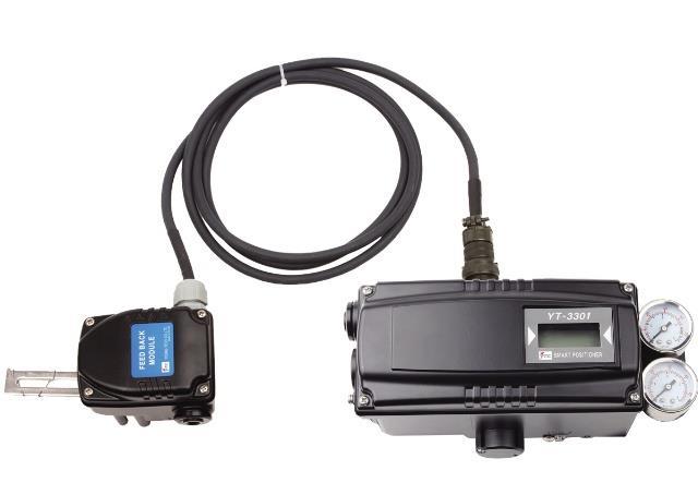
6 2. Product Description 2.1 General YT-3300 series Smart Valve Positioner accurately controls valve stroke in response to an input signal of 4-20mA from the controller. Built-in micro-processor optimizes the positioner s performance and provides unique functions such as Auto-Calibration, PID Control, Alarms, and HART Protocol Communications. 2.2 Main Features and Functions LCD display enables users to monitor the positioner status. Positioner operates normally during sudden changes in supply pressure and / or high vibration environment. Low air consumption level and low voltage use (8.5 V) yield to lower plant operating costs. The YT-3300 is compatible with most of controllers. Variable orifice can be used to minimize the hunting occurrence and optimize operating conditions. Valve system feedback is greatly improved by the accuracy and fast response of the YT Different valve characteristics can be adjusted Linear, Quick Open, Equal Percentage, and Custom which user can make 16 points characterizations. Tight Shut Close and Shut - Open can be set. PID parameters can be adjusted in the field without any additional communicator. A/M switch can be used to direct supply air to the actuator or to manually operate the positioner or valve. Split range 4-12mA or 12-20mA can be set. Operating temperature is -40 ~ 85 C. Manual Operation allows the user to operate the valve manually. 2.3 Label Description YT-3300/3301 Body Label A. Model: Indicates the model number of the positioner. B. Explosion Proof: Indicates certified explosion proof grade. C. Input Signal: Indicates input signal range. D. Operating Temp.: Indicates the allowable operating temperature. E. Supply Pressure: Indicates the supply pressure range. 6 YT-3300/3301 series
7 2.4 Product Number ** YT-3300 series can be used for direct-mounting application. ** YT-3301 standard cable length is 5 meters. Maximum cable length is 20 meters. 7 YT-3300/3301 series
8 2.5 Product Specification Model YT-3300L YT-3300R YT-3301L YT-3301R Acting Type Single Double Single Double Single Double Single Double Input Signal Min. Current Signal Supply Pressure 4~20mA DC 3.2mA(Standard), 3.8mA(Hart Included) 0.14~0.7 MPa (1.4~7 bar) Stroke 10~150 mm 0~90 10~150 mm 0~90 Impedance 20mA DC Air Connection PT, NPT 1/4 Gauge Connection PT, NPT 1/8 Conduit Entry PF(G) 1/2 Protection Grade IP66 Explosion Proof Ex ia IIC T6 / T5 Non-Explosion Proof Ambient Temp. Operating Temp. :-30~85 Operating Temp : -30 ~ 85 Sensor Temp: -40 ~ 120 Linearity ±0.5% F.S. (cable length: 5 m) Hysteresis 0.5% F.S.(cable length: 5 m) Sensitivity ±0.2% F.S (cable length: 5 m) Repeatability ±0.3% F.S.(cable length: 5 m) Flow Capacity Air Consumption Output Characteristic Vibration 70 LPM (Sup.=0.14 MPa) Below 2 LPM (sup = 0.14 MPa), Below 3 LPM (sup = 0.7MPa) Linear, Quick Open, EQ%, User Set (16 point) No Resonance upto 6G Humidity 5-95% 40 Communication Feedback Signal Material HART Communication 4~20mA (DC 10~30V) Aluminum Diecasting Weight 2.0kg Body: 2.2 kg Sensor: 0.6 kg Painting Epoxy Powder Coating Tested under ambient temperature of 20 C, absolute pressure of 760mmHg, and humidity of 65%. Please contact Young Tech Co., Ltd for detailed testing specification. * Explosion proof certification is in progress. 8 YT-3300/3301 series
9 2.6 Parts and Assembly YT-3300L & YT-3300R YT-3300L series exploded view YT-3300R series exploded view 9 YT-3300/3301 series
10 2.7 Parts and Assembly YT-3301L & YT-3301R 2.8 Product Dimension YT-3300L 10 YT-3300/3301 series
11 2.8.2 YT-3300R YT-3300R standard YT-3300R with L/S option 11 YT-3300/3301 series
12 2.8.3 YT-3301L YT-3301R 12 YT-3300/3301 series
13 3. Installation 3.1 Safety When installing a positioner, please ensure to read and follow safety instructions. Any input or supply pressures to valve, actuator, and / or to other related devices must be turned off. Use bypass valve or other supportive equipment to avoid entire system shut down. Ensure there is no remaining pressure in the actuator. 3.2 YT-3300/3301L Installation YT-3300/3301L should be installed on linear motion valves such as globe or gate type which uses spring return type diaphragm or piston actuators. Before proceeding with the installation, ensure following components are available. Positioner unit Feedback lever and lever spring Flange nut (bottom side of YT-3300/3301L) 4 pcs x hexagonal headed bolts (M8 x 1.25P) 4 pcs x M8 plate washer Installation Steps 1. Proper bracket must be made in order to adapt the positioner on the actuator yoke. Please consider following important points when a bracket is being designed. Positioner s feedback lever must be parallel to the ground at 50% of the valve stroke. Feedback lever connection with the pin of the actuator clamp should be installed in such a way that the valve stroke length coincides with the corresponding figure in mm marked on the feedback lever. Improper setting may cause poor linearity and may create unnecessary hunting during the operation. 2. Assemble the positioner with the bracket made in previous step by fastening the bolts. Please refer to the backside of the positioner for size of the bolts. The standard bolt size is M8 x 1.25P. Please contact Young Tech Co., Ltd for other bolt sizes. YT-3300L YT-3301L 13 YT-3300/3301 series
14 3. Attach the positioner with bracket to the actuator yoke DO NOT TIGHTEN POSITIONER COMPLETELY. 4. Connect positioner s feedback lever to the actuator clamp. The hole gap on the feedback lever is 6.5mm. The connection pin s outer diameter should be less than 6.3mm. 5. Connect supply pressure to the actuator temporarily. Supply enough supply pressure to the actuator in order to position the actuator clamp at 50% of the total valve stroke. 6. Insert connection pin into the feedback lever. The pin should be inserted when the actuator clamp is at 50% of the total valve stroke. Proper way to connect feedback lever, connection pin, and lever spring <YT-3300 and YT-3301 sensor> 7. Check if feedback lever is parallel to the ground at 50% of the valve stroke. If it is not parallel, adjust the bracket or feedback link bar to make parallel. Improper installation may cause poor linearity and may create unnecessary hunting during the operation. 8. Check the valve stroke. The stroke marks are indicated on the feedback lever of the positioner. Position the connection pin at the number on the feedback lever which corresponds to the desired valve stroke. To adjust, move the bracket, the connection pin or both. Proper way of Pin Insertion 14 YT-3300/3301 series
15 9. After installing the positioner, operate the valve from 0% to 100% stroke by using direct air to the actuator (manual position). On both 0% and 100%, the feedback lever should not touch the lever stopper, which is located on the backside of the positioner. If the feedback lever touches the stopper, the positioner should be installed further away from the yoke. Feedback lever should not touch lever stopper 0% ~ 100% valve stroke. 10. After the installation, tighten all of the bolts on the bracket, the feedback lever, and the connection pin. 3.3 YT-3300L Direct-Mounting Installation YT-3300L can be installed on direct-mounting / tube-less type actuator Installation Steps 1. Please remove the plug which blocks OUT port on the back of the YT-3300 unit. OUT ports on the side of the positioner should be blocked by plugs. Remove Block 15 YT-3300/3301 series
16 2. Mount YT-3300L onto actuator s yoke by using 2 bolts. As you mount the positioner, please be careful not to lose o-rings from the air channel. Please ensure that the lever adapter connection has been properly installed onto actuator s stem before tightly fastened. 3.4 YT-3300R Installation YT-3300R should be installed on rotary motion valve such as ball or butterfly type which uses rack and pinion, scotch yoke or other type of actuators which stem rotates 90 degrees. Before proceeding with the installation, ensure following components are available. Positioner unit Fork lever and lever spring Standard rotary bracket (included with the positioner) 4 pcs x hexagonal headed bolts (M8 x 1.25P) 4 pcs x M8 plate washer Bracket information YT-3300R series is supplied with standard bracket. This bracket can be used for both fork and NAMUR lever. Please refer to below table how to adjust the bracket. Markings of bolt holes Actuator stem A B C 30 x 80 x H20mm x 80 x H30mm x 130 x H30mm x 130 x H50mm YT-3300/3301 series
17 Using hexagonal bolts and washer, fasten YT-3300R with the supplied bracket. Do not tighten bolts completely before correct mounting of YT-3300R has been confirmed. Insert YT-3300R s main shaft into actuator s stem, and place the bracket align to the actuator s bolt holes. After the alignment, please fasten all of the bolts. 4. Connections 4.1 Safety Supply pressure should be clean and dry air avoiding moisture, oil or dust. Always recommended to use air filter regulator (i.e. YT-200 series). Young Tech Co., Ltd has not tested positioner s operation with any other gases other than clean air. Please contact Young Tech Co., Ltd for any questions. 4.2 Supply Pressure Condition Dry air with at least 10 lower than ambient temperature. Avoid from dusty air. Positioner s inner filter can only filter 5 micron or larger. Avoid oil. Comply with ANSI/ISA (R1981) or ISA S (R1981). Supply pressure range is 1.4 ~ 7 kgf/cm 2 ( kpa) Set air filter regulator s pressure level 10% higher than actuator s spring range pressure. 4.3 Piping Condition Ensure inside of pipe is clean of obstructions. Do not use pipeline that is squeezed or shows any type of damamges. Pipeline should have more than 6mm of inner diameter (10mm outer diameter) to maintain flow rate. 17 YT-3300/3301 series


18 The length of pipeline system should not be extremely long. Longer pipeline system may affect flow rate due to the friction inside of the pipeline. 4.4 Connection Actuator Single acting actuator YT-3300 Singe acting type positioner is set to use OUT1 port. OUT1 port should be connected with supply pressure port from actuator when using single acting type of spring return actuator. Singe acting linear (left) and rotary (right) type actuator Double acting actuator YT-3300 Double acting type positioner is set to use OUT1 and OUT2 port. As input signal increases, the supply pressure will be supplied through OUT1 port. Double acting linear (left) and rotary (right) type actuator Single acting actuator YT-3301 Single acting linear (left) and rotary (right) type actuator 18 YT-3300/3301 series
19 4.4.4 Double acting actuator YT-3301 Double acting linear (left) and rotary (right) type actuator 4.5 Connection Power Safety When installing in hazardous and explosive gas area, conduit tube or pressure-proof packing union must be used. The compound charging box should be the flameproof type and must be sealed completely. Conduit entry connection tap is PF 1/2 or G 1/2. Before connecting terminal, ensure that the power is off completely. Do not open the cover when the power is still alive. Please use ring-type rug to protect against vibration or any other external impact. Standard positioner operates on 4-20mA loop power. Positioner with PTM options must be supplied 10~28V DC. For L/S option, 12-24V DC must be supplied. For both options, it should not exceed 30V DC. Positioner should be grounded. Please use twisted cable with conductor section are 1.25mm 2 and that is suitable for 600V (complying to the conductor table of NEC Article 310.) The outer diameter of the cable should be between 6.35 ~ 10mm. Use shield wire to protect against electromagnetic field and noise. Please do not install the cable near high noise equipments, such as high-capacity transformer or motor. 19 YT-3300/3301 series
20 4.5.2 Terminal Overview Positioner Terminal IN +: Input Signal (+) IN -: Input Signal (-) FG: Ground OUT+: Feedback Signal (+) OUT-: Feedback Signal (-) Limit Switch Terminal Mechanical Type <YT-3300> 20 YT-3300/3301 series
21 Limit Switch Terminal Proximity Type <YT-3300> Ground 1. Ground must be done before operating the positioner. 2. Open terminal cover and locate ground terminal plate on the right hand bottom side of the terminal plate. The outer cable entry is located at outside of the terminal. Please make sure that the resistance is less than 100ohm. 3. When using external ground, use (+) screw driver to unscrew the ground bolts. Insert outside ground bolts and spring washer into ring type terminal of the ground cables and tighten them with bolts. 4. When using inside ground, use 3mm wrench to loosen locking bolts of the terminal box cover. 5. Adjustments 5.1 Limit Switch Adjustment YT-3300 series can have limit switch option. If user wants to adjust the position, please loosen cam bolts and adjust cam. Mechanical Type Proximity Type 21 YT-3300/3301 series
22 5.2 Auto/Manual Switch (A/M Switch) Auto/Manual Switch allows the positioner to be functioned as by-pass. If switch is set as Auto, the positioner will operate per input signal. If switch is set as Manual, the positioner will send supply pressure directly to the actuator. 5.3 Variable Orifice Adjustment Positioner can cause hunting with extremely small size of the actuator. To adjust flow rate to the actuator, variable orifice can be inserted. The sizes of orifice are 1 pie and 2 pie. 5.4 Option PCB Adjustment By adding option sub-pcb, the positioner can have options. There are 3 types of sub-pcb s HART only PTM only PTM + HART Installation Steps 1. Open the cover and remove the main PCB from the positioner. 2. Mount support PCB and plug sub-pcb into main PCB connector. Option Jumper. ** Option Jumper must be removed, when HART option included sub-pcb is being mounted. 22 YT-3300/3301 series

23 6. Operation 6.1 Safety Following process will operate valve and actuator. Before proceed with any AUTO Calibration, please separate valve from the entire system, so AUTO Calibration will affect entire valve process. 6.2 Button Description Positioner has 4 buttons, and they enable to perform various functions. Fig. 11: : Enter to main and sub menus, and save : Return to previous menu <UP> & : Move to next menu, and adjust. 6.3 Run Mode (RUN) After power connection to the positioner, Run Mode will be appeared on positioner s LCD screen within 6 seconds. RUN indicates that the positioner adjusts the valve stroke according to the receiving signal. There are six types of display message in RUN Mode. 1. Run PV: Process Value - valve stroke % 2. Run SV %: Set Value input signal 0~100% 3. Run SV ma: Set Value input signal 4~20mA 4. Run MV: Manipulate Valve Motor Manipulate Value (digit) 5. Run Vel: Velocity Current valve stem s velocity (digit) 6. Run Err: Error Difference between SV and PV (%) To change display, push + <UP> buttons at the same time. The display will change in the order indicated above. If + pushed, the order will be appeared in opposite order. By pressing, the display will return to RUN mode. 23 YT-3300/3301 series
24 6.3.1 Auto Calibration (AUTO CAL) Auto Calibration (AUTO CAL) automatically calibrates the positioner. AUTO CAL process takes about 2~3 minutes, and the duration of the process varies upon the size of the actuator. There are 3 types of AUTO CAL. Zero Point End Point KP, KI, KD RA / DA BIAS V_D AUTO 1 O O X X X X AUTO 2 O O O O O O AUTO HF O O O O O O BIAS X X X X O X It is recommend to perform AUTO2 calibration for initial positioner setting AUTO1 Calibration (AUTO1) AUTO1 changes zero and end points; however, KP, KI, KD will not be adjusted. It is recommended to perform AUTO1 when the positioner has been set by the valve manufacturer already, and the field user wants to re-calibrate the positioner. 6 seconds AUTO2 Calibration (AUTO2) AUTO2 changes all of the parameters. It is recommended to perform AUTO2 when the positioner has been installed on the valve for the first time. 6 seconds 24 YT-3300/3301 series
 AUTO CAL optimizes most of the valve actuator control values.")
25 6.3.2 Manual Mode (MANUAL) Manual mode is used to maneuver valve stem manually. During MANUAL, the positioner bypasses supply air to the actuator. positioner s save data valves. The movement of the stroke does not affect the 6 seconds <UP> Parameter Mode (PARAM) AUTO CAL optimizes most of the valve actuator control values. However, in some instances, hunting or oscillation may occur when the valve actuator control values are not optimized. Hunting or oscillation can be prevented by adjusting parameter values. Once parameter values have been changed, the changed values are being affected as soon as you save the value. To save the changes, please ensure to press ENTER button. There is no need to go back to RUN mode after changes are being made to observe the changes Dead-Zone (deadzone) Dead-Zone indicates the percentage of error allowance. In case of high level of packing friction, which may cause hunting, creating Dead-Zone can stable the valve operation. 6 seconds 2 times <UP>/ 25 YT-3300/3301 series

26 P value (KP) P value indicates the ratio of the compensation signal based on the percentage of error allowance. As the value increase, the positioner finds the target value quickly, but it is more likely to have hunting. 1time <UP>/ D value (Kd) D value indicates the derivative value of the compensation signal based on the percentage of error allowance. As the value increase, it is more likely to have hunting. As the value decreases, it can have poor linearity. 2 times I value (KI) <UP>/ I value indicates the additional compensation signal based on the percentage of error allowance. As the value increase, it is more likely to have hunting. As the value decreases, the positioner will move slowly to the target position. <UP> 26 YT-3300/3301 series
27 P_ (KP_), D_ (Kd_), I_(KI_) values P_, D_, and I_ values principles are same as P, D, and I values, but these values will be activated when the error percentage is within 1% Hand Calibration Mode (HAND CAL) The positioner can be manually calibrated by entering into Hand Calibration Mode Zero-Point (PV_ZERO) and End-Point (PV_END) for Valves PZ_ZERO adjusts the zero point of the valve, and PV_END adjusts the end point of the valve. 6 seconds <UP>/ Zero Adjustment <UP>/ End Adjustment Zero-Point (TR_ZERO) and End-Point (TR_END) for Transmitter TR_ZERO adjusts the zero point of the transmitter (4-20mA feedback), and TR_END adjusts the end point of the transmitter (4-20mA feedback) <UP>/<DOWN) Zero Adjustment Match feedback signal with 4mA End Adjustment 27 YT-3300/3301 series
 When reverse acting operating is")

 The feedback signal")

28 <UP>/<DOWN) Match feedback signal with 20mA End-Point Ratio for Valve (PE_TRIM) When reverse acting operating is used, End-Point can be adjusted within 10% of total valve stroke, without adjusting valve s zero point. 4 times <UP>/<DOWN) Normal / Reverse Feedback Signal (TR_NORM / REV) The feedback signal from the positioner can be viewed as normal or as reverse. Zero Adjustment 5 times Normal / Reverse HART Signal (HT_NORM / REVS) HART signal from the positioner can be viewed as normal or as reverse. Zero Adjustment 6 times 28 YT-3300/3301 series
29 6.3.5 Valve Mode (VALVE) Acting Adjustment (ACT) The positioner can be set as Direct Action (DA) or Reverse Action (RA). 6 seconds <UP>/ Characteristic Adjustment (CHAR) The valve characteristic can be set on the field s requirement. There are 3 types of characteristics linear (LIN), equal percentage (EQ), and quick open (QO). <UP>/ 29 YT-3300/3301 series
 Tight Shut Open allows the valve to open completely as the input signal reaches around 20mA. 6 seconds 6.3.5.5 Tight Shut Close (TSHUT CL) Tight Shut Close allows the valve to close completely as the input signal reaches around 4mA.")
30 User Characteristics (USER SET) In case positioner requires a specific characteristic, the valve characteristic curve can be made by selecting up to 16 points of the curve. 6 seconds 2 times <UP>/ <UP> Repeat step if necessary Tight Shut Open (TSHUT OP) Tight Shut Open allows the valve to open completely as the input signal reaches around 20mA. 6 seconds Tight Shut Close (TSHUT CL) Tight Shut Close allows the valve to close completely as the input signal reaches around 4mA. <UP>/ 6 seconds 4 times <UP>/ 30 YT-3300/3301 series
31 Split Range Mode (SPLIT) The valve can be operated by split range control 4~12mA or 12~20mA. 6 seconds 5 times <UP>/ Custom Zero Setting Mode (CST ZERO) Custom Zero Setting Mode allows the user to set any specific point as zero position. For example, the zero point can be set at input signal of 7mA. 6 times Custom End Setting Mode (CST ENd) <UP>/ Custom End Setting Mode allows the user to set any specific point as end position. For example, the end point can be set at input signal of 11mA. The difference between zero and end point must be greater or equal to 4mA. 7 times <UP>/ Interpolation Mode (ITP OFF / ON) Positioner can control the valve accurately if the feedback lever angle range is within designed range. For some instance, the angle exceeds the suggested range angle. Positioner can reduce the error through interpolation. 31 YT-3300/3301 series
32 8 times <UP>/ View Mode (VIEW) Different information can be shown on the positioner s LCD. 4 times <UP>/ Description YT-3300L VERSION HART V POL AddR Positioner model Main software version HART protocol version HART protocol channel address bias 25 BIAS value when valve position is at 25% bias 75 BIAS value when valve position is at 75% 0Y 0d FULL_OP FULL_CL VM NOR Erro VALUE I ABS Total used time duration. If a unit was used less than 1 minute, the time will not accumulate. Time elapsed for valve to fully open Time elapsed for valve to fully close. Type of valve stroke on LCD. (in percentage or in value) Error code or warning message. Current I value Absolute resistance value. 32 YT-3300/3301 series
33 7. Error and Warning Code 7.1 Error code Error Code Code Description and Cause Action MT ERR L MT ERR H CHK AIR Positioner is improperly installed. Positioner is not parallel to the ground at 50% point. Lever is at lower position than actual 50% point. Positioner is improperly installed. Positioner is not parallel to the ground at 50% point. Lever is at higher position than actual 50% point. Valve does not operate when positioner receive Full Open signal during the auto calibration. Re-install the positioner. Ensure the feedback lever does not touch the lever stopper at 0% and 100%. Re-install the positioner. Ensure the feedback leer does not touch the lever stopper at 0% and 100%. Check supply pressure level. RNG ERR C D Adjust bracket so the positioner Operating angle is too small due to can be mounted closer to improper positioner installation. actuator. Error of 10% or more persists more than 1 minute. Perform BIAS calibration. No valve movement. Check setting pressure of actuator. High level of valve friction Changes in setting pressure of actuator. I-value reaches at maximum or minimum limit. Perform auto calibration. Changes in valve friction. Check setting pressure of actuator. Changes in setting pressure of actuator. 7.2 Warning code Warning Code Description Action B F Re-install the positioner. Ensure the feedback lever does not Pv Span Pv Zero range is below 500. touch the lever stopper at 0% and The angle of feedback lever is too small. 100%. After re-installation, perform AUTO1. Full open/close elapsed time is less Use variable orifice. than 1 second. Use larger actuator. Actuator size is too small. 33 YT-3300/3301 series
34 G Pv is below 100. The angle of feedback lever is too large. Re-install the positioner. Ensure the feedback lever does not touch the lever stopper at 0% and 100%. After re-installation, perform AUTO1 H Re-install the positioner. Ensure the feedback lever does not Pv is over touch the lever stopper at 0% and The angle of feedback lever is too large. 100%. After re-installation, perform AUTO1 34 YT-3300/3301 series
35 8. PST (Partial Stroke Test) 8.1 Glossary INTERVAL Interval time between current PST and next PST in the schedule mode LATENCY Latency for next movement after valve move LIMIT TM limit the stroke time between START PO and TARGET 1,2 Perform PST Run PST immediately PST Partial Stroke Test PST MODE Running mode for PST PST NOW Run PST immediately PST OFF Stop PST Schedule PST REC1,2,3 Record of PST result PST SCHD PST Scheduling mode START PO Start position when PST runs TARGET 1 1st target position TARGET 2 2nd target position TOL Tolerance of start Position when PST runs 8.2 Introduction TARGET 2 START PO TOL TARGET 1 LATENCY INTERVAL When PST runs by PST NOW or SCHD, if valve position is in the range of TOL from START PO, Positioner supply or vent air until the valve reach the TARGET 1, 2. But PST test will stop if valve position goes out of the TOL or doesn t reach TARGET1, 2 within the LIMIT TM. After the valve position reach the TARGET 1, 2, the valve will pause during the LATENCY and move back to the START PO. The valve will be under ready state during the INTERVAL time after completing 1 cycle of PST in the SCHD mode. 35 YT-3300/3301 series


36 8.3 How to run PST on the field device Set PST Configuration Check Parameter values and configure them if you need PARAMETER VALUE DEFAULTE UNIT START PO % TARGET % TARGET 2 NA, NA % INTERVAL Day TOL % LIMIT TM Sec LATENCY Sec Set PST Mode To run PST, select a PST mode. There are 3 mode for running PST. Mode Description PST OFF Stop PST Schedule. It s a default mode PST SCHD Run PST immediately. After PST complete, it turns back to the previous mode PST NOW PST runs repeatedly by interval value Check PST Result It will record or memorize maximum three PST results. The longest stroke time from START PO to the TARGET 1,2 or Error messages will be recorded NAME VAULE DEFAULT PST REC1 OOT,LTO,NR, 0-600(sec) 0 PST REC2 OOT,LTO,NR, 0-600(sec) 0 PST REC3 OOT,LTO,NR, 0-600(sec) 0 Error Message OOT When the valve position is out of tolerance(tol) from Start Position(START PO) LTO When the valve doesn t reach to the target position within the Limit Time(LIMIT TM) NR When the valve doesn t move 36 YT-3300/3301 series

37 8.4 How to run PST on the HART communication Set PST configuration Check the Parameter values in PST Configuration under Diagnostic and configure them if you require Run PST There are 2 ways to run PST. One way is to start PST by set Parameter value as scheduled and the other way is by running Perform PST. Perform PST is the same as PST NOW on the Field Device menu Check PST Result You can see the results on PST result menu. 37 YT-3300/3301 series
38 9. Main Software Map 38 YT-3300/3301 series
39 Manufacturer: Young Tech Co., Ltd #3022, Hagun-ri, Yangchon-myeon Kimpo-si, Kyeonggi-do, South Korea Tel: Fax: Copyright Young Tech Co., Ltd. All Rights Reserved. 39 YT-3300/3301 series
SMART POSITIONER YT-3300/3301 SERIES
 SMART POSITIONER YT-3300/3301 SERIES PRODUCT MANUAL VERSION 1.02 Contents 1. Introduction 5 1.1 General information for the users. 5 1.2 Manufacturer Warranty 5 2. Product Description.. 6 2.1 General..
SMART POSITIONER SS-3300 SERIES
 SMART POSITIONER SS-3300 SERIES PRODUCT MANUAL VERSION 1.02 Contents 1. Introduction 4 1.1 General information for the users. 4 1.2 Manufacturer Warranty 4 2. Product Description.. 5 2.1 General.. 5 2.2
Electro-Pneumatic Converter YT-940 SERIES
 Electro-Pneumatic Converter YT-940 SERIES PRODUCT MANUAL VERSION 1.00 Contents 1. Introduction 3 1.1 General information for the users. 3 1.2 Manufacturer Warranty 3 1.3 Explosion Proof Warning. 4 2. Product
VOLUME BOOSTER RELAYS YT-300 / 305 SERIES
 VOLUME BOOSTER RELAYS YT-300 / 305 SERIES PRODUCT MANUAL VERSION 1.02 Contents 1. Introduction 3 1.1 General information for the users. 3 1.2 Manufacturer Warranty 3 2. Product Description.. 4 2.1 General..
LOCK UP VALVES YT-400/405/430/435 SERIES
 LOCK UP VALVES YT-400/405/430/435 SERIES PRODUCT MANUAL VERSION 1.00 Contents 1. Introduction 3 1.1 General information for the users. 3 1.2 Manufacturer Warranty 3 2. Product Description.. 4 2.1 General..
SANP ACTING RELAYS YT-520/525/530 SERIES
 SANP ACTING RELAYS YT-520/525/530 SERIES PRODUCT MANUAL VERSION 1.02 Contents 1. Introduction 3 1.1 General information for the users. 3 1.2 Manufacturer Warranty 3 2. Product Description.. 4 2.1 General..
PRODUCT MANUAL YT-2700
 SMART POSITIONER PRODUCT MANUAL VERSION 1.08 Contents 1. Introduction... 4 1.1 General Information for the users... 4 1.2 Manufacturer Warranty... 4 1.3 Explosion Proof Warning (Only for Intrinsic safety
Electro-Pneumatic Positioner YT-1000L (Linear Type)
") Electro-Pneumatic Positioner YT-1000L (Linear Type) Ordering Symbols: YT-1000L Model Acting Type Explosion Proof Lever Type Orifice Type Connection Type Ambient Temp YT-1000 L S Single Acting m ExdmIIBT5
Electro-Pneumatic Positioner YT-1000L (Linear Type) Ordering Symbols: YT-1000L Model Acting Type Explosion Proof Lever Type Orifice Type Connection Type Ambient Temp YT-1000 L S Single Acting m ExdmIIBT5
YT-3400 / 3450 SERIES
 SMART POSITIONER YT-3400 / 3450 SERIES PRODUCT MANUAL VERSION 1.10 Contents 1. Introduction... 5 1.2 Manufacturer Warranty... 5 1.3 Explosion Proof Warning... 6 2. Product Description... 7 2.1 General...
YT-3400 / 3450 SERIES YT-3400 YT-3450 VERSION 1.17
 SMART POSITIONER YT-3400 / 3450 SERIES PRODUCT MANUAL YT-3400 YT-3450 VERSION 1.17 Contents 1. Introduction... 5 1.1 General Information for the users... 5 1.2 Manufacturer Warranty... 5 1.3 Explosion
YT-3400 / 3450 SERIES YT-3400 YT-3450 VERSION 1.20
 SMART POSITIONER YT-3400 / 3450 SERIES PRODUCT MANUAL YT-3400 YT-3450 VERSION 1.20 Contents 1. Introduction... 5 1.1 General Information for the users... 5 1.2 Manufacturer Warranty... 5 1.3 Explosion
SSR. Smart Valve Positioner.
 Smart Valve Positioner Smartest valve control device meeting a dynamic performance and a precise setting with a piezoelectric technology and an optimized auto-calibration program Features Auto-Calibration
Lock Up Valves YT-400, YT-405 USER'S MANUAL
 USER'S MANUAL YTC V.1.01 Product Description Lock Up Valve, YT-400 (YT-405), senses the main supply pressure and shuts down the air flow when the pressure is lower than setting level to avoid system shutdown
Smart performance with innovative and ever-strong coil drive even under harsh working environments
 Smart Valve Positioner SS2 inear / Rotary Smart performance with innovative and ever-strong coil drive even under harsh working environments Easy and quick auto-calibration Detecting RA (reverse acting)
SSL. Smart Valve Positioner.
 Smart Valve Positioner Smartest valve control device meeting a dynamic performance and a precise setting with a piezoelectric technology and an optimized auto-calibration program Features Auto-Calibration
ITS 300 & 500 SERIES POSITION MONITORING INSTALLATION AND OPERATION MANUAL
 ITS 300 & 500 SERIES POSITION MONITORING ITS 300 & 500 SERIES POSITION MONITORING INSTALLATION AND OPERATION MANUAL (Explosion proof Ex d II T6) (Doc no: ITS00312-M) 74-6, hun Ui-Dong, Won Mi-Gu, Bucheon
Tapped exhaust port. Sturdy, simple, reliable design. Easy to add on Feedback. High gain pilot valve. Simple calibration, external zero adjustment
 Electropneumatic Positioner Sturdy, simple, reliable design High gain pilot valve Built in gauge ports Tapped exhaust port Easy to add on Feedback Unit F5 Simple calibration, external zero adjustment Bright
Electropneumatic Positioner and Pneumatic Positioner Type 3760 JIS
 Electropneumatic Positioner and Pneumatic Positioner Type 3760 Application Single-acting positioners for direct attachment to pneumatic control valves. An electric standardized signal of 4 to 20 ma or
Electropneumatic Positioner and Pneumatic Positioner Type 3760 JIS
 Electropneumatic Positioner and Pneumatic Positioner Type 3760 Application Single-acting positioners for direct attachment to pneumatic control valves. Supplied with an electric input signal of 4 to 20
Instruction Manual. PLT Series. 1. General Specification. 2. Installation. 3. Wiring. 4. Function. 5. Setting & Calibration
 4 Digit Display, 4-20mA Output Instruction Manual (Digital Differential Pressure Transmitter) 1. General Specification 2. Installation 3. Wiring 4. Function 5. Setting & Calibration 1 4 20 1 Differential
ACV-10 Automatic Control Valve
 ACV-10 Automatic Control Valve Installation, Operation & Maintenance General: The Archer Instruments ACV-10 is a precision automatic feed rate control valve for use in vacuum systems feeding Chlorine,
MANUAL KPS Pressure Control Valve
 TetraTec Instruments GmbH Gewerbestrasse 8 71144 Steinenbronn Deutschland E-Mail: info@tetratec.de Tel.: 07157/5387-0 Fax: 07157/5387-10 MANUAL Pressure Control Valve *** VERSION 1.0 *** Update: 17.11.2006
YT-3300 / 3301 / 3302 / 3303 / 3350 / 3400 /
 Smart positioner YT-3300 / 3301 / 3302 / 3303 / 3350 / 3400 / 3410 / 3450 Series SIL Safety Instruction. Supplement to product manual July. 2015 YTC Ver 1.06 1 Table of contents 1 Introduction... 3 1.1
2600T Series Pressure Transmitter Models 264DC Differential and 264HC Gage Level Transmitters. Kent-Taylor
 INDUSTRIAL INSTRUMENTS AND CONTROLS SPECIALIST Kent-Taylor 2600T Series Pressure Transmitter Models 264DC Differential and 264HC Gage Level Transmitters Features Include Base accuracy : ±0.075% Span limits
INSTRUCTION MANUAL Pressure Relief Device LPT
 INSTRUCTION MANUAL Pressure Relief Device LPT 5COV475800 LPT REV00 CONTENT: 1 SAFETY 1.1 Safety instructions 2 1.2 Specified applications 2 1.3 Safety notes on the equipment operation 2 2 PRESSURE RELIEF
Model 130M Pneumatic Controller
 Instruction MI 017-450 May 1978 Model 130M Pneumatic Controller Installation and Operation Manual Control Unit Controller Model 130M Controller is a pneumatic, shelf-mounted instrument with a separate
Ultrasonic level transmitter and indicator
 Ultrasonic level transmitter and indicator No contact with the product Compact design with polycarbonate housing (electronics and display). Remote display available on request Very good resistance in corrosive
FTC FasTrak Compact INSTRUCTION MANUAL 4049
 FTC FasTrak Compact INSTRUCTION MANUAL 4049 STI S.r.l has taken every care in collecting and verifying the documentation contained in this Instruction Manual. The information herein contained are reserved
T i m i n g S y s t e m s. RACEAMERICA, Inc. P.O. Box 3469 Santa Clara, CA (408)
") RACEAMERICA T i m i n g S y s t e m s Demo Tree Controller Owner s Manual Models 3204D, 3204DW & 3204DX Rev D RACEAMERICA, Inc. P.O. Box 3469 Santa Clara, CA 95055-3469 (408) 988-6188 http://www.raceamerica.com
RACEAMERICA T i m i n g S y s t e m s Demo Tree Controller Owner s Manual Models 3204D, 3204DW & 3204DX Rev D RACEAMERICA, Inc. P.O. Box 3469 Santa Clara, CA 95055-3469 (408) 988-6188 http://www.raceamerica.com
INSTRUCTION MANUAL. FLOAT TYPE LEVEL TRANSMITTER HT-100R Series HITROL CO., LTD.
 HITROL CO., LTD. HEAD OFFICE.FACTORY.R&D INSTITUDE HITROL CO.,LTD 141, Palhakgol-gil, Jori-eup Paju-si, Gyeonggi-do, Korea TEL. : (00)-82-31-950-9700 FAX. : (00)-82-31-943-5600 www.hitrol.com INSTRUCTION
D10S/D20S Wall/Post Mount Inflator Quick Start Manual
 PART NUMBER SERIAL NUMBER D10S/D20S Wall/Post Mount Inflator Quick Start Manual Please read and save these instructions. Read carefully before attempting to assemble, install, operate or maintain the product
FTC130 Transmitter. Operating Manual
 Seite 1 von 11 FTC130 Transmitter Fast Thermal Conductivity Analyzer Operating Manual 1.09KD180724CWI1V05 Messkonzept GmbH Seite 2 von 11 1. Intended Use... 3 2. Description... 4 3. Measuring gases and
Level transmitters and indicators Series LU Ultrasonic level transmitter and indicator for liquids and solids
 Level transmitters and indicators Series LU Ultrasonic level transmitter and indicator for liquids and solids No contact with the product Compact design with polycarbonate housing (electronics and display).
PX3005. Rangeable Industrial Pressure Transmitter M-5721/1018
 PX3005 Rangeable Industrial Pressure Transmitter INTRUCTION HEET -5721/1018 hop online at omega.com e-mail: info@omega.com For latest product manuals: omegamanual.info ! Pressure / differential pressure
Mounting and Operating Instructions EB 8546 EN. Type 4708 Supply Pressure Regulators. Translation of original instructions. Type Type
 Type 4708 Supply Pressure Regulators Translation of original instructions Type 4708-53 Type 4708-64 Type 4708-12 Mounting and Operating Instructions Edition March 2018 Note on these mounting and operating
MUELLER. A Wall Type. Indicator Post. Reliable Connections. General Information 2. Technical Data/ Dimensions 3. Installation 4-5.
 Installation Instructions manual MUELLER table of contents PAGE A-20814 Wall Type General Information 2 Technical Data/ Dimensions Installation 4-5 Maintenance 6 Parts 7 Indicator Post! WARNING: 1. Read
Differential Pressure Transmiter
 Differential Pressure Transmiter Description The is an economical alternative to established differential pressure transmitters. It combines state of the art electronics and a high performance sensor;
MUELLER. A A Adjustable. Vertical Indicator Posts. Reliable Connections. General Information 2. Technical Data 3.
 Installation Instructions manual MUELLER table of contents PAGE A-20806 A-20807 Adjustable General Information 2 Technical Data 3 Dimensions 4 Installation 5-6 Parts 7 Maintenance 8 Vertical Indicator
OPERATING AND MAINTENANCE MANUAL
 Series 4300 Engineered Performance TABLE OF CONTENTS 0 INTRODUCTION 1 1 Scope 1 2 Description 1 3 Specifications 1 0 INSTALLATION 1 1 Mounting 1 2 Piping 1 1 Connecting Process Pressure 2 2 Vent Connections
Operating Instructions Part No
 DIGITAL AUTOMATIC TYRE INFLATOR Operating Instructions Part No. 11.0578 Thank you for selecting this Jamec Pem Automatic Tyre Inflator. Please read this manual before carrying out any installation or service
3" 24" 80A 600A DN80 DN600 Body size The largest size manufactured : 60" (1500A) Disc form Damper type Trim materials Trim treatment
 Disc form Damper type Trim materials Trim treatment") STANDARD SPECIFICATION SS-CE-600B-A JUL. 2004 600B Disc Damper Type Butterfly Valve GENERAL 600B STANDARD SPECIFICATIONS BODY Series 600B This series 600B is a wafer type butterfly valve, designed to be
STANDARD SPECIFICATION SS-CE-600B-A JUL. 2004 600B Disc Damper Type Butterfly Valve GENERAL 600B STANDARD SPECIFICATIONS BODY Series 600B This series 600B is a wafer type butterfly valve, designed to be
SP200 Electropneumatic Smart Positioner
 3439650/5 IM-P343-29 CH Issue 5 SP200 Electropneumatic Smart Positioner Installation and Maintenance Instructions 1. Index 2. Safety information 3. Technical information 4. Options 5. Installation 6. Electrical
Richards Industries Basic Siemens PS2 Positioner Functions
 Basic Siemens PS2 Positioner Functions Wiring 1 Supply Pressure Use clean, dry instrument air for the supply pressure. In general, on valves that are normally closed, you need 35-40 psi of supply pressure
Components for air preparation and pressure adjustment. OUT port position ( ) connected Rear side. of IN port. Air tank. directly.
 connected Rear side. of IN port. Air tank. directly.") Components preparation and pressure adjustment ABP Overview ABP is a component that enables boosting by s only up to twice primary pressure (.0MPa max.) in combination with using air tank but not using
Components preparation and pressure adjustment ABP Overview ABP is a component that enables boosting by s only up to twice primary pressure (.0MPa max.) in combination with using air tank but not using
Electropneumatic Positioner Type 4763 Pneumatic Positioner Type 4765
 Electropneumatic Positioner Type 4763 Pneumatic Positioner Type 4765 Application Single-acting positioner for attachment to pneumatic control valves. Supplied with either an electric input signal from
RS(H)10,15 USER MANUAL. Read the complete manual before installing and using the regulator.
10,15 USER MANUAL. Read the complete manual before installing and using the regulator.") RS(H)10,15 USER MANUAL Read the complete manual before installing and using the regulator. WARNING INCORRECT OR IMPROPER USE OF THIS PRODUCT CAN CAUSE SERIOUS PERSONAL INJURY AND PROPERTY DAMAGE. Due to
RS(H)10,15 USER MANUAL Read the complete manual before installing and using the regulator. WARNING INCORRECT OR IMPROPER USE OF THIS PRODUCT CAN CAUSE SERIOUS PERSONAL INJURY AND PROPERTY DAMAGE. Due to
Manual Actuated Boiler Blowdown Valves
 Manual Actuated Boiler Blowdown Valves Installation and Maintenance Instructions 1. Safety information 2. General product information 3. Installation 4. Operation 5. Maintenance 6. Spare parts p.1 1. Safety
IDL01. Battery Powered Precision Digital Gauge for Leak Testing. Stainless Steel Sensor. class 0.05
 IDL0 Battery Powered Precision Digital Gauge for Leak Testing Stainless Steel Sensor class 0.05 Nominal pressure from 0 00 mbar up to 0... 00 bar Special characteristics modular sensor concept data logger
RAI-M series RUDDER ANGLE INDICATOR SYSTEM
 RUDDER ANGLE INDICATOR SYSTEM RAI-M series SEAFIRST ENGINEERING CO 45-16, Ga Um Dong, Chang Won, Kyong Nam Korea Tel : 82 55 267 1645 Fax ; 82 55 266 1646 http://www.seafirst.co.kr GENERAL Seafirst Rudder
Hand-held pressure calibrator with integrated pump Model CPH6600
 Calibration technology Hand-held pressure calibrator with integrated pump Model CPH6600 WIKA data sheet CT 16.01 Applications Calibration service companies and service industry Measurement and control
Type 3709 Pneumatic Lock-up Valve. Translation of original instructions. Mounting and Operating Instructions EB 8391 EN
 Type 3709 Pneumatic Lock-up Valve Translation of original instructions Mounting and Operating Instructions EB 8391 EN Edition July 2017 Note on these mounting and operating instructions These mounting
Instruction Manual Contact Pressure Vacuum Gauge
 MS10 Instruction Manual Contact Pressure Vacuum Gauge Table of Contents 1. Safety Instructions 2. Intended Applications 3. Product Description and Functions 4. Installation 5. Commissioning 6. Maintenance
RTX 1000H Series. Versatile Transmitters for a World of Pressure. GE Measurement & Control. Features
 GE Measurement & Control RTX 1000H Series Versatile Transmitters for a World of Pressure GE Measurement & Control is renowned for the design and manufacture of compact and rugged high performance pressure
Integral type Differential pressure flowmeter VNT Series
 Integral type Differential pressure flowmeter VNT Series OUTLINE VH series Wafer-Cone differential pressure flowmeter and high precision differential pressure transmitter are integrated into one flowmeter.
PRO-50 Instrument Supply Regulator
 Features CRN Approved The PRO-50 Regulator has been granted a Canadian Registration Number. Sour Service Capability Available in NACE configurations that comply with NACE MR0175/MR0103. Environmental limits
AMT-Ex Dewpoint Transmitter
 AMT-Ex Dewpoint Transmitter Instruction Manual Alpha Moisture Systems Alpha House 96 City Road Bradford BD8 8ES England Tel: +44 1274 733100 Fax: +44 1274 733200 email: mail@amsytems.co.uk web: www.amsystems.co.uk
Model 4000 Pressure Controller
 FEATURES Multiple Configurations The 4000 series pressure controller can be configured into either proportional only or proportional plus reset mode with a minimum of parts. Rugged Design Die cast aluminum
Instruction and Maintenance Manual
 Instruction and Maintenance Manual GRYF OXY ZM 02/100/2 E Contact GRYF HB, spol. s r.o. Cechova 314 Havlickuv Brod 580 01 tel.: +420 569 426 627 fax: +420 569 426 627 www.gryf.eu ver.: 11.2.2015 OEM module
Pressure Measurement Single-range transmitters for general applications
 Siemens A 207 Overview Application The SITRANS P Compact pressure transmitter is designed for the special requirements of the food, pharmaceutical and biotechnology industries. The use of high-grade materials
SX150A. Features. Typical Applications. Description
 Datasheet -- Pressure Sensors: Measurement Type: Absolute; 0 psia to 150 psia, Unamplified, Representative photograph, actual product appearance may vary. Due to regional agency approval requirements,
DPC-30 DPC-100. Reference Manual
 DPC-30 DPC-100 Reference Manual 1. Introduction 1.1 Description The Martel DPC Digital Pneumatic Calibrator improves upon traditional dial gauge pneumatic calibrators. The Martel DPC improves accuracy,
Fisher DVI Desuperheater Venturi Inline
 Instruction Manual DVI Desuperheater Fisher DVI Desuperheater Venturi Inline Contents Introduction... 1 Scope of Manual... 1 Description... 1 Principle of Operation... 2 Installation... 3 Operating Instructions...
IPH 2 & IPX 2. Features Type 4X & Explosion-Proof Current-to-Pressure (I/P) Transmitters. Approved for Use with Natural Gas.
 Transmitters. Approved for Use with Natural Gas.") February 2018 Description These 2-wire (loop-powered) I/P transmitters accept a current signal (such as 4-20mA) from a DCS, PLC or PC-based control system. They convert the current signal to a pneumatic
February 2018 Description These 2-wire (loop-powered) I/P transmitters accept a current signal (such as 4-20mA) from a DCS, PLC or PC-based control system. They convert the current signal to a pneumatic
100C Air Compressor Kit
 10010 100C Air Compressor (standard mounting bracket, CE Spec) 10014 100C Air Compressor (no leader hose or check valve, CE Spec) 10016 100C Air Compressor (with Omega Bracket, CE Spec) IMPORTANT: It is
Installation and Operation Manual
 Installation and Operation Manual WIKA FLR-SBDF / BLR-SBDF Magnetic Level Transmitter (Please retain for future usage) Contact: Gayesco-WIKA USA, L.P. 229 Beltway Green Boulevard Pasadena, TX 77503 www.wika.com
Float Operated Level Controllers
 CONTENTS Float Operated Level Controllers IM0015 Nov. 2014 PAGE Introduction 1 Scope 1 Description 1 Specification 1 Control Installation 2 INTRODUCTION Side Mount Back Mount Prior to installing, the instructions
IMPORTANT SAFETY INSTRUCTIONS
 IMPORTANT SAFETY INSTRUCTIONS CAUTION - To reduce risk of electrical shock: - Do not disassemble. Do not attempt repairs or modifications. Refer to qualified service agencies for all service and repairs.
YT-300 / 305 / 310 / 315 / 320 / 325 Series
 Volume Booster YT-300 / 305 / 310 / 315 / 320 / 325 Series SIL Safety Instruction. Supplement to product manual Apr. 2016 YTC Ver. 2.01 1 Table of contents 1 Introduction... 3 1.1 Purpose of this document...
Electronic gas volume corrector model DGVC-04
 Electronic gas volume corrector model DGVC-04 1. Introduction The following user s manual gives information about the installation, configuration, usage and storage of the electronic gas volume corrector
The Ins and Outs of I/P Transducers
 The Ins and Outs of I/P Transducers By Mark B. Levine, ControlAir Inc. General description I/P transducers are versatile instruments that use an electrical control signal to proportionally regulate gas
Electropneumatic Transducer (I/P) Installation, Operation and
 Installation, Operation and") Nitra NCP1 Series Electropneumatic Transducer (I/P) Installation, Operation and Maintenance Instructions Ordering Information Contents Part Number I/P Transducers Output Range Input psig bar Section Description
Nitra NCP1 Series Electropneumatic Transducer (I/P) Installation, Operation and Maintenance Instructions Ordering Information Contents Part Number I/P Transducers Output Range Input psig bar Section Description
PTG100 Precision Test Gauge
 PTG100 Precision Test Gauge User Manual PD1007 Rev B 03/28/2014 Palmer Instruments Inc. 234 Old Weaverville Road Asheville, NC 28804 Toll Free: 800-421-2853 Phone: 828-658-3131 Fax: 828-658-0728 Email:
AUTOMATIC TIRE INFLATOR # MW-60, MW-60-4WAY & MW-64HP
 USER MANUEL AUTOMATIC TIRE INFLATOR # MW-60, MW-60-4WAY & MW-64HP TIRE EQUIPMENT MANUFACTURER 1.866.409.RACK WWW.MARTINSINDUSTRIES.COM info@martinsindustries.com PARTS Verify that the following components
97C COMPRESSOR KIT 12V PART NO C COMPRESSOR KIT 24V PART NO C COMPRESSOR KIT PART NO
 97C COMPRESSOR KIT 12V PART NO. 00097 97C COMPRESSOR KIT 24V PART NO. 02497 98C COMPRESSOR KIT PART NO. 00098 97C 98C IMPORTANT: It is essential that you and any other operator of this product read and
Model 6812C Dual Lane Scoreboard Owner s Manual
 The Leader in Event Critical Timing Electronics Model 6812C Dual Lane Scoreboard Owner s Manual Portatree Eliminator Compatible Rev A RaceAmerica, Inc. P.O. Box 3469 Santa Clara, CA 95055-3469 (408) 988-6188
I/P Transducer Positioner Module
 I/P Transducer Positioner Module VRC P/N: 7958032 Installation, Operation and Maintenance Instructions 2.09 [53.1] 1.30 [32.9] 2.97 [75.5] 0.78 [19.8] 0.18 [4.4] 1.42 [36.1] n.18 MOUNTING HOLES (2) PLACES
MUELLER A A Non-Adjustable. Vertical Indicator Posts. Reliable Connections. General Information 2. Technical Data 3.
 Installation Instructions manual MUELLER table of contents PAGE A-20808 General Information 2 Technical Data 3 Dimensions 4 A-20809 Non-Adjustable Installation 5-6 Parts 7 Maintenance 8 Vertical Indicator
Instruction and Maintenance Manual
 Instruction and Maintenance Manual GRYF OXY Z 02/100/2 E Contact GRYF HB, spol. s r.o. Cechova 314 Havlickuv Brod 580 01 tel.: +420 569 426 627 fax: +420 569 426 627 Czech Republic www.gryf.eu Technical
P9000 DESCRIPTION. For parts requiring RoHS compliance, please contact factory. P February /6
 P9000 High accuracy through digital compensation High thermal stability Rugged stainless steel construction Ideal for test stands High burst pressure limit DESCRIPTION The P9000 Series is a range of advanced,
Model PDT Dewpoint Transmitter
 Model PDT Dewpoint Transmitter Instruction Manual Alpha Moisture Systems Alpha House 96 City Road Bradford BD8 8ES England Tel: +44 1274 733100 Fax: +44 1274 733200 email: mail@amsytems.co.uk web: www.amsystems.co.uk
Type N-10, N-11 Hazardous Area Non-incendive Transmitters
 Electronic Pressure Catalog > Hazardous Area > N-10, N-11 Type N-10, N-11 Hazardous Area Non-incendive Transmitters Applications Natural gas compressors Wellhead monitoring Pipeline pressure General industrial
EP500 Advanced ATEX Electropneumatic Positioner
 3.568.5275.306 IM-P343-46 CH Issue 2 EP500 Advanced ATEX Electropneumatic Positioner Installation and Maintenance Instructions 1. Safety information 2. Technical Information 3. Installation 4. Commissioning
High-performance submersible pressure transmitter For level measurement Model LH-10
 Electronic pressure measurement High-performance submersible pressure transmitter For level measurement Model LH-10 WIKA data sheet PE 81.09 Applications Level measurement in rivers and lakes Deep well
200 PSI COMPRESSORS - MODEL NUMBERS
 200 PSI COMPRESSORS - MODEL NUMBERS 380C AIR COMPRESSOR KIT PART NO. 38033 480C AIR COMPRESSOR KIT PART NO. 48043 380C 480C IMPORTANT: It is essential that you and any other operator of this product read
General Specifications
 General Specifications YVP110 Advanced Valve Positioner GS 21B04C01-01E FEATURES Model YVP110 FOUNDATION fieldbus TM Valve Positioner accepts digital communication to control a pneumatic actuator mounted
Operating Instructions Part No
 DIGITAL AUTOMATIC TYRE INFLATOR Operating Instructions Part No. 11.0545 Thank you for selecting this Jamec Pem Automatic Tyre Inflator. Please read this manual before carrying out any installation or service
E8AA. Pressure Sensor of Stainless Steel Construction Is Ideal for a Wide Range of Applications. Pressure Sensor (Stainless Steel Diaphragm)
") Pressure Sensor (Stainless Steel Diaphragm) CSM DS_E_3_1 Pressure Sensor of Stainless Steel Construction Is Ideal for a Wide Range of Applications Incorporates double diaphragms consisting of SUS316L stainless
Pressure Sensor (Stainless Steel Diaphragm) CSM DS_E_3_1 Pressure Sensor of Stainless Steel Construction Is Ideal for a Wide Range of Applications Incorporates double diaphragms consisting of SUS316L stainless
LVU2800 Series. Ultrasonic Level Transmitter
 LVU2800 Series Ultrasonic Level Transmitter 2 of 23 INTRODUCTION / TABLE OF CONTENTS Step One The LVU2800 Series is a general purpose ultrasonic level transmitter that provides a loop powered 4 20 ma output.
GasSense NDIR User Manual
 INDEX INDEX... 1 1. OVERVIEW... 2 2. TECHNICAL DATA... 3 3. SPECIFICATIONS... 4 4. PRODUCT DESCRIPTION... 5 4.1 Mechanical details... 5 4.2 Piping... 7 4.3 Connections... 7 5. INSTALLATION... 10 6. CALIBRATION
THE MF-400 SERIES. Operating and Service Manual. Series includes all variants of MF-400/401
 THE MF-400 SERIES Operating and Service Manual Series includes all variants of MF-400/401 Issue A October 2013 1 TABLE OF CONTENTS 1. Description... 3 2. Installation... 3 3. Operation... 4 4. Special
400C & 450C DUAL PERFORMANCE VALUE PACKS
 (Chrome) PART NO. 40013 (Silver) PART NO. 45012 (Chrome) PART NO. 45013 IMPORTANT: It is essential that you and any other operator of this product read and understand the contents of this manual before
Mounting and Operating Instructions EB 8546 EN. Supply Pressure Regulator Type Fig. 1 Supply pressure regulators
 Supply Pressure Regulator Type 4708 Type 4708-5352 on Type 3730 Positioner Type 4708-52 with filter receptacle Type 4708-6252 on Type 3372 ctuator Fig. Supply pressure regulators Mounting and Operating
420C AIR COMPRESSOR KIT PART NO C AIR COMPRESSOR KIT PART NO
 420C AIR COMPRESSOR KIT PART NO. 42042 460C AIR COMPRESSOR KIT PART NO. 46043 420C 460C IMPORTANT: It is essential that you and any other operator of this product read and understand the contents of this
Transmitter CS 21 Operation Manual
 Transmitter CS 21 Operation Manual Content Page For your Safety 3 General Description 3 Detection Principle 4 Operational Notes 4 Design 4 Mounting Position of CS21 5 Mounting 6 Installation of Electrical
UBEC 1AT. AUTO TANK Fill System Installation, Operation, & Setup Instructions
 Document Number: XE-ATA5PM-R1A UBEC 1AT AUTO TANK Fill System 08899155 Installation, Operation, & Setup Instructions Rev170906-EB-FRC PHYSICAL: 1302 WEST BEARDSLEY AVE ELKHART, IN 46514 WWW.ELKHARTBRASS.COM
MODEL GT820 OXYGEN SENSOR
 INSTRUCTION MANUAL MODEL GT820 OXYGEN SENSOR 70046 The information and technical data disclosed by this document may be used and disseminated only for the purposes and to the extent specifically authorized
GM Series Dual-Block Multi-Function Gas Control Valves
 Installation Sheets Manual 121 Gas Combustion Combination Controls and Systems Section G Technical Bulletin GM Issue Date 0297 GM Series Dual-Block Multi-Function Gas Control Valves Figure 1: GM Series
Dimensions [All numbers in brackets are in millimeters.] K4-2 US (supplied) 1/2" Centered (Default)
![Dimensions [All numbers in brackets are in millimeters.] K4-2 US (supplied) 1/2 Centered (Default)](/thumbs/89/97801636.jpg "Dimensions [All numbers in brackets are in millimeters.] K4-2 US (supplied) 1/2 Centered (Default)") Proportional damper actuator, non-spring return, Multi-Function Technology Torque min. Control to 0 VDC (DEFULT) Feedback to 0 VDC (DEFULT) For proportional modulation of dampers in HVC systems. The is
Proportional damper actuator, non-spring return, Multi-Function Technology Torque min. Control to 0 VDC (DEFULT) Feedback to 0 VDC (DEFULT) For proportional modulation of dampers in HVC systems. The is
Torque Tube TB300 Digital Transmitters
 Page 1 of 7 7E.300-E Issue 4-2009 Description Series TB300 torque tube liquid level instruments utilize the buoyancy exerted on a displacer when immersed in a liquid. The buoyancy on the displacer is proportional
Technical Datasheet. D Series SMART Pressure Transmitter Model: DPC D-Series. Key Features. Series Overview. Product applications
 Technical Datasheet D Series SMART Pressure Transmitter Model: DPC-2000 Key Features ATEX - Flameproof and Intrinsically Safe IECEx - Flameproof and Intrinsically Safe SIL 2 certificate Compliant to NAMUR