Operating manual. for. tapping points of the EM15/EE15 series
|
|
|
- Samuel McGee
- 6 years ago
- Views:
Transcription


1 for tapping points of the
2 Table of Contents Table of Contents Introduction General Description of the EM15 and EE15 tapping points series Intended use Personnel requirements For your safety Symbols used Essential safety information Safety features Description Design of the EM15 and EE15 series tapping points Structural and functional description Technical data Connection options Labelling Installation Putting the tapping point into operation Taking the unit out of service Faults Maintenance, cleaning and repairs Regular maintenance work and visual inspections Regular cleaning Repair information Returns GES_EM+EE_15_0517.docx
3 1. Introduction 1.1 General Validity This user manual applies to EM15 and EE15 tapping points. Manufacturer Spectron Gas Control Systems GmbH Fritz-Klatte-Straße 8 D Frankfurt Germany Telephone: Fax: info@spectron.de Internet: Publication date May 2017 Retention and completeness This user manual is a component of the EM15 and EE15 tapping points and must be kept in a location visible for the authorised group of persons at all times. At no time may chapters be removed from this user manual. A missing user manual or missing pages particularly the "For your safety" chapter must be replaced immediately. Copyright This user manual contains copyrighted information. It must not be photocopied, reproduced, translated or copied onto data carriers, either in full or in part, without prior authorisation. All rights reserved. Updates This user manual is not subject to updates by Spectron Gas Control Systems GmbH. Changes to this user manual may take place without prior notification notification. 1.2 Description of the EM15 and EE15 tapping points series The tapping points of the EM15 and EE15 series are specifically designed for integration in laboratory furniture. They provide high purity and special gasses for the optimal supply of laboratory devices. The main task of the tapping points is to reduce the respective inlet pressure to the required outlet pressure in the specific laboratory applications. The gas supply can be interrupted or released to the laboratory appliances using the shut-off valve on the pressure regulator or the optionally configurable service valve. 3 GES_EM+EE_15_0517.docx
4 1. Introduction 1.3 Intended use Intended use The EM15 tapping points are intended for use with non-corrosive gases up to quality 6.0. The EE15 tapping points are additionally intended for use with corrosive gases up to quality 6.0. The permitted gases and pressure areas for the tapping points are specified on the product label and the gas type label. Tapping points are used in most cases as a second pressure control and shut off unit following a pressure control panel at the end points of a piping system. They are used to additionally reduce the already relatively constant pipeline pressure downstream of the pressure control panel to a highly constant outlet pressure towards the application. Tapping points may be used in an ATEX area because they do not have a potential ignition source of their own (ignition hazard assessment in accordance with DIN EN ). Foreseeable misuse The following operating conditions are deemed to constitute misuse: Operation with gases that are not specified on the product label Use with gases in their liquid condition Operation in an environment that has a higher than normal amount of dust particles or humidity as well as operation in an environment with salty, oily or acidic atmospheres Operation in environments outside a temperature range of -20 C to +60 C Operation in environments that can cause vibrations on or impacts to the fitting Failure to comply with the locally applicable legal regulations and provisions The use of oil and grease when handling the fitting Failure to follow this manual Failure to carry out inspection and maintenance work Failure to heed the information on the product label and in the product data sheet Pressurisation counter to the normal direction of flow 1.4 Personnel requirements Definition of an authorised person A person qualifies as an authorised person if they have received technical training and have received technical instructions on the entire system and the associated dangers gas cylinder type of gas gas cylinder valve pressure regulator and have also successfully completed training in the field of "Supply of pressurised gases". Tasks of the operating personnel The operating personnel must identify faults or irregularities and remove where possible and permissible. Requirements placed on operating personnel To be able to fulfil the tasks, the operating personnel must meet the following requirements: The operating personnel must have received instruction in the operation of the tapping point from an authorised person and must have read and understood this operating manual in its entirety. 4 GES_EM+EE_15_0517.docx

5 2. For your safety 2.1 Symbols used Note! Important! Warning! Danger! DANGER! This symbol warns that there is a "risk of fatal injury" or a health hazard for the personnel. 2.2 Essential safety information Note! The following safety notes are intended to be used as an addition to the already applicable national accident prevention regulations and laws. Existing accident prevention regulations and laws must be complied with at all times. Various laws, regulations, rules and directives are authoritative when handling compressed gasses. These must be observed depending on each type of gas. The following list lays no claim to be exhaustive; it merely represents a selection of the most important sections: EU Directive 2009/104/EC (Work Equipment Directive) EU Directive 1999/92/EC (ATEX 137) EU Directive 98/24/EC (risks related to chemical agents at work) TRBS (technical regulations on industrial safety and health) publications TRGS (German technical rules for hazardous substances) TRAS (technical regulations on plant safety) publications DGUV DGUV GUV-R 132 BG RCI leaflet M034 EIGA documents Principles of prevention Explosion protection rules Safety data sheets for the gases used Avoiding ignition hazards caused by electrostatic charges 5 GES_EM+EE_15_0517.docx
6 2. For your safety 2.3 Safety features Possible hazard Caution! The EM15 and EE15 tapping points do not have a relief valve. To protect the downstream fittings, pressure vessels and pipes against overpressure due to a possible failure of the tapping point pressure regulator, a separate safety device that complies with any relevant regulations must be installed. Danger! If oxygen comes into contact with oil or grease, there is a risk of fire due to a chemical reaction. Prevention measures Keep all parts that come into contact with oxygen free from oil and grease. Danger! Gas escaping into the ambient air can ignite; there is a risk of fire and explosion. Danger! The tapping point may be damaged by unauthorised changes or alterations and may no longer work as intended. There is a risk of the system malfunctioning, catching fire or getting damaged. Danger! If tapping points are used that are not suitable for the relevant gas and pressure range, there is a risk of a fire or explosion occurring as a result of a chemical reaction. Danger! If the tapping point is used outside the specified ambient temperature range, there is a risk of the system malfunctioning, catching fire or getting damaged. Danger! Improper handling and impermissible use can lead to danger for the user, other persons as well as damage to the device. If dirt particles get into the pressure regulator of the tapping point, this can damage it or cause it to malfunction. Smoking and naked flames are strictly prohibited near gas supply equipment. No changes or alterations may be carried out without written permission from technically authorised manufacturer personnel. The tapping point must be suitable for the relevant gas and the pressure ranges involved. Only use for the gases indicated on the device. If there are no gas types specified on the tapping point, you have to ask the manufacturer which gases it can be used with. On no account must the tapping point be put into operation without this information. Do not use in ambient temperatures below 30 C and above +60 C. Use and handle the tapping point only as described in this operating manual. It must be ensured that no dirt particles of any kind can get into the pressure regulator. 6 GES_EM+EE_15_0517.docx
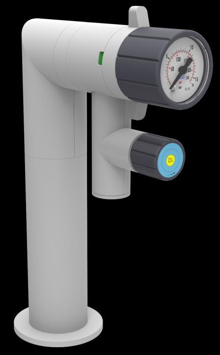
 Used as the connection point for the")
7 3. Description 3.1 Design of the EM15 and EE15 series tapping points Elements of the tapping point Item Designation Function 1 Rear wall connection (RWA) Used as the connection point for the gas supply system 2 Integrated shut-off valve Seals the piping system as long as no tapping point is installed and is used as the primary pressure shut-off valve for installed tapping points 3 Fastening screws Self-tapping screws for fastening the RWA to the furniture wall 4 Pressure regulator Diminishes the inlet pressure P1 to the adjusted outlet pressure P2 5 Union nut Fastens the tapping points to the RWA 6 Rotary lever Used to actuate the shut-off valve 7 Open/closed display Shows the position of the shut-off valve 8 Hand wheel Used for setting the outlet pressure 9 Pressure gauge Indicates the current outlet pressure 10 Gas type label Shows the type of gas the tapping points may be used for 11 Gas outlet The following consumer unit can be connected to this component. As depicted in the image, a service gas valve can optionally be installed here. It is used to shut off the outlet pressure regulator. In all cases, the connection thread is a female ¼ -NPT. 7 GES_EM+EE_15_0517.docx

8 3. Description 3.2 Structural and functional description The EM15 and EE15 tapping points are specifically designed for use with laboratory furniture. The design of the fittings consists of a connecting part, called the rear wall connection, which supports various methods of installation: panel-mounted, surface-mounted, wall-mounted, ceiling- or column-mounted. After the installation of the rear wall connection with an integrated shut-off valve, the main component, the pressure regulator, is screwed on. Only a metallic sealing is utilised, without additional sealing elements. The pressure regulator has different outlet and connection variations downstream. As an option, a control / shut-off valve can be installed in the outlet of the pressure regulator. There is also the option of screwing a control / shut-off valve or a wall outlet (without pressure regulator) directly onto the rear wall connection. The rear wall connection contains a non-return valve that makes it possible to uninstall a tapping point from a rear wall connection at any time without having to vent the pipe arranged upstream beforehand. This also makes it possible to include points in the structure at which a tapping point can be connected later. The entire gas supply system can continue to operate uninterrupted while the tapping point is connected at a later time. The outlet pressure can be adapted to new requirements by replacing the tapping point. The pressure regulator's shut-off valve is actuated using what is called the rotary lever. Depending on the position, a colour mark on the pressure regulator is either red to indicate the closed position or green to indicate the open position of the shut-off valve. Open position Closed position The pressure regulator's pressure setting is controlled using the hand wheel, which encloses the pressure gauge. Turning the hand wheel clockwise increases the pressure. Turning the hand wheel counterclockwise decreases the pressure. 8 GES_EM+EE_15_0517.docx
9 3. Description 3.3 Technical data Note! The technical data can be taken from the Spectron data sheet for the relevant product. If this is not available, you can view and download it at The maximum inlet and outlet pressures and the gas type are indicated on the product label. 3.4 Connection options Inlet pressure connections on the RWA: AW / AE model 1/4"-NPT female thread EP / EF model 1/4"-NPT female thread DC / ES model 1/4"-NPT female thread SC model 6 mm pipe end for clamping ring screw connections Outlet pressure connection: 1/4"-NPT female thread or 6 mm pipe end for clamping screw connections or as soldering/welding end 3.5 Labelling Labelling example Gas type identification with labels in accordance with EN EM15-AW-10-0-V-DL P1: 40 bar P2: 10 bar (manufacturing date) 9 GES_EM+EE_15_0517.docx


10 Ø Ø Ø Operating manual 4.1 Installation Rear wall connection assembly Rear wall connection ¼-NPT female and M24x1 male assembly from the front / fixing from the front with screws Ø Arrange the furniture wall as depicted in the drilling pattern drawing Screw in self-tapping screws and fasten the rear wall connection to the furniture wall Snap on covering caps and attach the gas type label Rear wall connection ¼-NPT female and M24x1 male assembly from the front / fixing from behind with nut Arrange the furniture wall as depicted in the drilling pattern drawing Screw on M24x1 nuts and fasten the rear wall connection to the furniture wall Snap on covering caps and attach the gas type label Rear wall connection with adapter plate using the drilling pattern of the previous series Ø Arrange the furniture wall as depicted in the drilling pattern drawing Fasten the adapter plate to the furniture wall using the supplied self-tapping screws Fasten the rear wall connection to the adapter plate using the supplied M5x8 countersunk screws Snap on covering caps and attach the gas type label 10 GES_EM+EE_15_0517.docx


11 Rear wall connection ¼-NPT female assembly from behind / fixing from the front with screws Arrange the furniture wall as depicted in the drilling pattern drawing Mount the rear wall connection from the backside of the furniture and fix from the front side with the screws M4 for pitch circle dia 38 and M5 for for pitch circle dia 31. Snap on covering caps and attach the gas type label Assembling and screwing together the rear wall connection and tapping point Special attention is needed when assembling the rear wall connection and the actual tapping point (this equally applies to the column-mounted and the ceiling connection). Both connecting parts have a hexagonal geometry that serves to aid positioning and acts as an anti-twist lock. It is very important that both hexagonal geometries are threaded in the correct position when manually screwing on the SW20 union nut. While doing this, no force may be applied, for example, by using a tool. A tool may only be used for the final tightening of the union nut when both parts of the anti-twist lock are interlocked. Otherwise, the tapping point will be incorrectly positioned and the rear wall connection will be damaged. As a result of this, gas-tightness will not be achieved in the connection between the rear wall connection and tapping points. SW20 Anti-twist lock Note! The hexagonal anti-twist lock can only be repositioned in 60 increments in accordance with its geometric proportions. If the tapping point is to be rotated by 90 relative to its current position, the rear wall connection must first be rotated by GES_EM+EE_15_0517.docx

12 4.1.3 Assembly of the shut-off valve or VM/VE gas-discharge valve SW20 SW17 Insert the shut-off valve or wall outlet into the hexagonal holes of the installed rear wall connection in accordance with section When doing so, please observe the notes from section Manually tighten the SW 20 union nut until resistance can be felt. Hold the shut-off valve or wall outlet with the SW 17 open-ended spanner and tighten the SW 20 union nut with a torque of Nm. Check to see if the tightness of the rear wall connection is correct. Place the T-shaped plastic half-shells around the valve and connect them. Place the round plastic half-shells around the rear wall connection and connect them. Insert the plastic rings into the joined valve shells. Affix the gas type label. 12 GES_EM+EE_15_0517.docx
 of the hand wheel always slide")

13 4.1.4 Assembly/disassembly of the hand wheel The hand wheel is disassembled by simply removing it. During the subsequent assembly of the hand wheel, which occurs by simply attaching it, it must be ensured for all tapping points described below that the brackets (1) of the hand wheel always slide over the white plastic stop ring (2). Note: The white plastic ring is not present for each tapping point. Two plastic rings can occasionally be present Assembly of the AW type tapping point SW20 Close the tapping point shut-off valve by turning the rotary lever clockwise to the closed position. A red mark must be identifiable in both lateral recesses. Carefully insert the AW tapping point into the hexagonal holes of the rear wall connection while rotating the SW 20 union nut. When doing so, please observe the notes from section Tighten the union nut with a torque of Nm. Manually hold the fitting. Check the tightness of the rear wall connection. To do so, open the shut-off valve by turning both handle cams counter-clockwise and properly test the connection points for leaks. Place the plastic half-shells around the rear wall connection and connect them. 13 GES_EM+EE_15_0517.docx

14 Ø Operating manual Assembly of the AE type tapping point Ø SW20 Arrange the furniture wall as depicted in the drilling pattern drawing. Install the rear wall connection according to section Close the tapping point shut-off valve by turning the rotary lever clockwise to the closed position. A red mark must be identifiable in both lateral recesses. Carefully insert the AE tapping points into the hexagonal holes of the rear wall connection while rotating the SW 20 union nut. When doing so, please observe the notes from section Tighten the union nut with a torque of Nm. While doing so, manually hold the fitting. Check the tightness of the rear wall connection. To do so, open the shut-off valve by turning both handle cams anti-clockwise and properly test the connection points for leaks. Place the plastic half-shells around the rear wall connection and connect them. 14 GES_EM+EE_15_0517.docx
 (the screw-in connection is not included in the scope of delivery) For wall installation,")
15 4.1.7 Assembly of the ES type tapping point 3 Ø Ø Arrange the furniture wall as depicted in the drilling pattern drawing. Properly wrap the 1/4 -NPT screw-in connection using Teflon tape and screw into the rear wall connection (1) (the screw-in connection is not included in the scope of delivery) For wall installation, insert 2 Ø 8 mm screw anchors into the wall holes and screw the rear wall connection into place using two wooden countersunk screws. Screw anchors and wooden countersunk screws are not included in the scope of delivery. Attach the rear wall connection cover (2) to the rear panel. Close the tapping point shut-off valve by turning the rotary lever clockwise to the closed position. A red mark must be identifiable in both lateral recesses. Carefully insert the ES tapping point into the hexagonal holes of the rear wall connection while rotating the SW 20 union nut (3). When doing so, please observe the notes from section Tighten the union nut with a torque of Nm. While doing so, manually hold the fitting. Check the tightness of the rear wall connection. To do so, open the shut-off valve by turning the handle cams counter-clockwise and test the connection points for leaks. Place the plastic half-shells (4) around the union nut and connect them. 15 GES_EM+EE_15_0517.docx
, lever inserts (2), label (3) and cover (4) from the tapping point.")

16 4.1.8 Assembly of the EP type tapping point Arrange the furniture wall as depicted in the drilling pattern drawing. Remove the hand wheel (1), lever inserts (2), label (3) and cover (4) from the tapping point. This must be done with great care and caution because the pressure gauge can be damaged very easily when removing the hand wheel. Insert the now partially disassembled EP tapping point through the drilled holes on the back of the furniture wall. For up to 5mm furniture wall thickness: Use the supplied countersunk screws, screw the cover (4) to the plastic housing of the tapping point through the furniture wall. While doing so, the torque setting of the Bosch industry cordless screwdriver must not be set higher than because the cover can deform when using a higher tightening torque. For more than 5mm up to 8mm furniture wall thickness: Do not use the cover (4). Instead of that countersink the furniture bores and screw the supplied countersunk screws to the plastic housing of the tapping point directly through the furniture wall. Affix the label in the direction displayed above (red points in perpendicular direction). Slide the lever inserts into the corresponding slots. Carefully attach the hand wheel. Connect the tapping point to the back of the piping system and properly and professionally check the tightness of the installation. 16 GES_EM+EE_15_0517.docx


17 4.1.9 Assembly of the EF type tapping point Arrange the furniture wall as depicted in the drilling pattern drawing. Remove the hand wheel, handle cams, cover plate and wall liner from the tapping point. This must be done with great care and caution because the pressure gauge can be damaged very easily when removing the hand wheel. Insert the now partially disassembled EF tapping point through the drilled holes on the back of the furniture wall. For up to 5mm furniture wall thickness: Use the supplied countersunk screws, screw the cover (4) to the plastic housing of the tapping point through the furniture wall. While doing so, the torque setting of the Bosch industry cordless screwdriver must not be set higher than because the cover can deform when using a higher tightening torque. For more than 5mm up to 8mm furniture wall thickness: Do not use the cover (4). Instead of that countersink the furniture bores and screw the supplied countersunk screws to the plastic housing of the tapping point directly through the furniture wall. Affix the label in the direction displayed above (red points in perpendicular direction). Slide the handle cams into the corresponding slots. Carefully attach the hand wheel. Slide the aluminium ring (5) onto the angled outlet screw connection and attach it using the screwed-in thread pin. Connect the tapping point to the back of the piping system and properly and professionally check the tightness of the installation. 17 GES_EM+EE_15_0517.docx
 to the furniture cover using the self-tapping screws Attach the cover (2) to the adapter plate.")
18 Ø Operating manual Assembly of the DC type tapping point Ø SW Arrange the furniture cover as depicted in the drilling pattern drawing. Fasten the adapter plate (1) to the furniture cover using the self-tapping screws Attach the cover (2) to the adapter plate. Insert the pipe angle (3) into the adapter plate using the flange side with four holes and fasten it with both M5x8 countersunk screws. Place the L-shaped plastic half-shells (4) on both sides around the pipe angle and connect them. Screw four self-tapping screws into the flange with eight holes to attach the L-shaped plastic halfshells. Close the tapping point shut-off valve by turning the rotary lever clockwise to the closed position. A red mark must be identifiable in both lateral recesses. Carefully insert the DC tapping points (5) into the hexagonal holes of the flange of the pipe angle while rotating the SW 20 union nut. When doing so, please observe the notes from section Tighten the union nut with a torque of Nm. While doing so, manually hold the fitting. Check the tightness of the rear wall connection. To do so, open the shut-off valve by turning the handle cams counter-clockwise and properly test the connection points for leaks. Place the plastic half-shells (6) around the rear wall connection and connect them. 18 GES_EM+EE_15_0517.docx

19 Assembly of the SC type tapping point SW20 Column SW32 Drill through the furniture plate at the specified location. Diameter range of 25 mm 30 mm! Remove the washer and SW32 hexagon nut of the column. Insert the column into the hole of the furniture plate and fasten it from the bottom of the furniture using the washer and SW32 hexagonal nuts. Close the tapping point shut-off valve by turning the rotary lever clockwise to the closed position. A red mark must be identifiable in both lateral recesses. Carefully insert the SC tapping point into the hexagonal holes of the column flange while rotating the SW 20 union nut. When doing so, please observe the notes from section Tighten the union nut with a torque of Nm. While doing so, manually hold the fitting. Check the tightness of the rear wall connection. To do so, open the shut-off valve by turning the handle cams counter-clockwise and properly test the connection points for leaks. Place the plastic half-shells around the rear wall connection and connect them. 19 GES_EM+EE_15_0517.docx
 and the covers (2) carefully. The ¼ -NPT thread of the fitting (e.g. compression ring fitting or hose connector), which has to be mounted into the outlet must professionally be wrapped with PTFE tape.")
20 Mounting of fittings SW The explanation regarding mounting of fittings into EM/EE 15 armatures is shown on type AW as an example. This may be transferred to any other type. Remove the cover of gas outlet or the control valve: Remove the ring (1) and the covers (2) carefully. The ¼ -NPT thread of the fitting (e.g. compression ring fitting or hose connector), which has to be mounted into the outlet must professionally be wrapped with PTFE tape. The first thread turn must not be covered with PTFE tape. Screw the prepared fitting (4) into the outlet (3) manually. Hold the outlet with a spanner (SW17) on the flat parts. This prevents the outlet (3) from loosening / turning out of the regulator, which may cause a leakage. Use an appropriate tool to get the connection gas tight. Put the covers back together onto the outlet and add the ring on the bottom. Before start-up with process gas leak test the connections in the outlet appropriately. 20 GES_EM+EE_15_0517.docx
21 4.2 Putting the tapping point into operation Caution! Before start-up, check the label to see whether the tapping point is suitable for the intended purpose. Make sure that the tapping point has previously been flushed out with inert gas if corrosive gases are to be used. Flushing must not take place against the normal flow direction, otherwise dirt particles could get into sensitive areas of the fitting. Always turn the shut-off valve and the control / shut-off valve as far as they will go when opening or closing them! Note! The numbering used in the following table corresponds to that of section 3.2 in this user manual. Step Activity 1 Ensure that the tapping point is labelled (10) for the present gas type all protective caps have been removed the assembly has been properly completed according to the previous section all connectors have been correctly installed and checked for leaks the pressure regulator is depressurized 2 Connect the consumer unit to the gas outlet (11) 3 Slowly open the shut-off valve (6a) by turning the rotary lever (6b) clockwise from a horizontal position to a perpendicular position. 4 Adjust the pressure regulator (3) to the desired outlet pressure by turning the hand wheel (7) clockwise. Make sure that an audible vibration of the pressure regulator is prevented, otherwise the pressure regulator could become damaged. Vibrations can, for example, occur when large volumes are filled (long, downstream lines or large-volume containers). 4 Check the entire tapping point and all detachable connections again for gas-tightness. 5 Open the control / shut-off valve (11), if applicable. 6 The withdrawal of gas to supply the connected consumers can take place. 21 GES_EM+EE_15_0517.docx
22 4.3 Taking the unit out of service Taking out of operation or interrupting operation for a short period For brief interruptions of work, closing off the downstream control / shut-off valve from the tapping point pressure regulator (if applicable) is sufficient. To do so, the control / shut-off valve hand wheel must be turned clockwise to the end. Taking out of operation or interrupting operation for a longer period Step Activity 1 Close the shut-off valve of the pressure regulator. To do so, continue to turn the control knob with the two cams behind the hand wheel to the pressure setting until the cams are in a horizontal position and the red mark on the side of the pressure regulator is visible. 2 Completely release the pressure of the pressure regulator by withdrawing gas. 3 Carry out a visual check of the pressure gauge to ascertain whether the pressure has been reduced. 4 If applicable: Also close the process gas valve. 5. Faults DANGER! In the event of any possible interference, immediately close the shut-off valve of the pressure regulator and take the tapping point out of operation. 22 GES_EM+EE_15_0517.docx
23 6. Maintenance, cleaning and repairs 6.1 Regular maintenance work and visual inspections Regular maintenance work To ensure the tapping point remains in perfect working order and a constantly high level of operational safety and reliability is maintained, it should be checked by a specialist once a year. Regular visual inspections Visual inspection of all parts for Damage Function Leaks Integrity/stability Corrosion Interval Regular inspections at intervals of 12 months and each time the device is put into operation make an important contribution to the cost-effectiveness and preservation of the value of the fittings. Note! If you determine defects during the visual inspection, do not take the tapping point into operation! Immediately have the tapping point checked by the manufacturer or by an authorised specialist company. 6.2 Regular cleaning Warning! Detergents or disinfectants can corrode and ruin gaskets inside the fittings. Do not use cleaning or disinfectants for cleaning! Severe contamination can lead to operational malfunctions. If it becomes necessary to clean the tapping point, use only a damp, lint-free cloth. 6.3 Repair information Caution! Repairs may only be carried out by expert personnel in repair shops authorised by the manufacturer. After repairs, the entire tapping point must be checked in accordance with the original Spectron inspection instructions. Safe and reliable operation can only be guaranteed if original spare parts are used. Note! The manufacturer accepts no liability for damage resulting from unauthorised repairs or modifications carried out by the user or third parties without the express written approval of the manufacturer. 6.4 Returns If the tapping point is returned to the manufacturer for testing, maintenance or repair, and it has been in contact with corrosive and toxic gases, it is imperative that it is purged with inert gas. 23 GES_EM+EE_15_0517.docx
24 Spectron Gas Control Systems GmbH Fritz-Klatte-Straße Frankfurt Germany Telephone: Fax: info@spectron.de Internet: 24 GES_EM+EE_15_0517.docx
for the of and the EM55-1
 Operating Manua al for the Tapping Points of the EM55-1/EM55-2/EM55-3/ /EM55-4 series and the EE55-1/EE55-2/EE55-3/EE55-4 series EM55-1 Contents Contents... 2 1. Introduction... 3 1.1 General... 3 1.2
Operating Manual for the Cylinder and Line Pressure Regulators of the M51/M52/M53 series and E51/E52/E53 series
 Operating Manua al for the Cylinder and Line Pressuree Regulators of the M51/M52/M53 series and E51/E52/E53 series Contents Contents... 2 1. Introduction... 3 1.1 General... 3 1.2 Description of the cylinder
Instruction manual. for. high purity gas pigtails 200 bar / 300 bar
 Instruction manual for high purity gas pigtails 200 bar / 300 bar Contents Contents... 2 1. Preface... 3 1.1 Overview... 3 1.2 General... 3 1.3 Intended use... 4 1.4 Personnel requirements... 4 2. For
for Series FE51/52/53-SP
 Operating Manua al for cylinder pressure regulators with purge device Series FE5/52/53-SP Series FE2-SP Contents Contents... 2. Introduction... 3. General information... 3.2 Description of the Series FE5/52/53-SP
Instruction manual. for. purge and connection block SBE/3
 Instruction manual for purge and connection block SBE/3 Contents Contents... 2 1. Introduction... 3 1.1 General... 3 1.2 Description of the purge and connection blocks of series SBE/3... 3 1.3 Intended
KTM OM-2 SPLIT BODY FLOATING BALL VALVES INSTALLATION AND MAINTENANCE INSTRUCTIONS
 Before installation these instructions must be fully read and understood SECTION 1 - STORAGE 1.1 Preparation and preservation for storage All valves should be properly packed in order to protect the parts
THE HF-300 SERIES. Operating and Service Manual. Series includes all variants of HF-300/301
 THE HF-300 SERIES Operating and Service Manual Series includes all variants of HF-300/301 Issue A July 2015 1 TABLE OF CONTENTS 1. Description... 3 2. Installation... 3 3. Operation... 4 3.1. Spring Loaded...
THE BP-301 SERIES. Operating and Service Manual. Series includes all variants of BP-301 (LF 0.1Cv / MF 0.5Cv)
") THE BP-301 SERIES Operating and Service Manual Series includes all variants of BP-301 (LF 0.1Cv / MF 0.5Cv) Issue B October 2015 1 TABLE OF CONTENTS 1. Description... 3 2. Installation... 3 3. Operation...
THE BP-301 SERIES Operating and Service Manual Series includes all variants of BP-301 (LF 0.1Cv / MF 0.5Cv) Issue B October 2015 1 TABLE OF CONTENTS 1. Description... 3 2. Installation... 3 3. Operation...
Operating and maintenance manual Filter and reducing station Series / 1.0
 Operating and maintenance manual Filter and reducing station Series 961 04.2017 / 1.0 Original instructions ARCA Regler GmbH. All rights reserved. Cover picture background: Freepik.com ARCA Regler GmbH
MODEL 200 KNIFE GATE VALVES INSTALLATION & MAINTENANCE MANUAL
 MODEL 200 KNIFE GATE VALVES INSTALLATION & MAINTENANCE MANUAL Index 1. List of components / General arrangement 2. Description 3. Handling 4. Installation 5. Actuators / Operation 6. Maintenance a. Changing
Operation Manual Piston Sensed Gas Pressure Regulators
 687 Technology Way Napa, CA 94558 Phone: (707) 259-0102 FAX: (707) 259-0117 www.aptech-online.com Operation Manual Piston Sensed Gas Pressure Regulators (Models KT9, KT10, Welded KT10, KT12) Table of Contents:
THE MF-400 SERIES. Operating and Service Manual. Series includes all variants of MF-400/401
 THE MF-400 SERIES Operating and Service Manual Series includes all variants of MF-400/401 Issue A October 2013 1 TABLE OF CONTENTS 1. Description... 3 2. Installation... 3 3. Operation... 4 4. Special
Mounting and Operating Instructions EB 2558 EN. Self-operated Pressure Regulators. Type Pressure Build-up Regulator
 Self-operated Pressure Regulators Type 2357-31 Pressure Build-up Regulator with safety function and integrated excess pressure valve Type 2357-31 with non-return unit at port C Ports A and B with soldering
Mounting and operating instructions EB 2530 EN. Self-operated Pressure Regulator. Pressure Reducing Valve Type M 44-2
 Self-operated Pressure Regulator Pressure Reducing Valve Type M 44-2 Type M 44-2, connection G 1 4, K VS = 0.15 Type M 44-2, connection G 1, K VS = 6 Fig. 1 Type M 44-2 Pressure Reducing Valve Mounting
AREA VALVE SERVICE UNITS
 AREA VALVE SERVICE UNITS. Unit 8, McKenzie Industrial Park, Tel No.: 44 (0) 161 428 7200 Bird Hall Lane, Fax No.: 44 (0) 161 428 7010 Stockport, Email: info@p3-phoenix.com U.K., SK3 0SB www.p3-phoenix.com
Installation and operating manual. Pneumatic control station LK product no: PCS 1-10
 LK product no: PCS 1-10 Article no: 74503 Revision:8 Article no: 74503 Revision: 8 2 (23) Contents 1. General information... 5 2. Safety precautions... 5 2.1 Significance of symbols... 5 2.2 Explanatory
Installation & Operation Manual Proven Quality since 1892
 Content 1. ERIKS operating companies 2. Product description 3. Requirements for maintenance staff 4. Transport and storage 5. Function 6. Application 7. Installation 8. Maintenance 9. Service and repair
Ball valve. Operating instructions for series. Version BA Print-No TR MA DE Rev001
 Ball valve Operating instructions for series Version BA-2016.02.05 Print-No. 300 587 TR MA DE Rev001 We reserve the right to make technical changes. Read carefully before use. Save for future use. ASV
Instrument Operating Manual
 Instrument Operating Manual INDEX NO. SUBJECT PAGE 1 INFORMATION 3 2 SAFETY 4 3 INTENDED USE 4 4 COMMISSIONING & OPERATION 5 5 MAINTENANCE 6 2 INFORMATION The pressure gauges described in the operating
THE BP-690 SERIES. Operating and Service Manual. Series includes all variants of BP-LF/MF-690/691
 THE BP-690 SERIES Operating and Service Manual Series includes all variants of BP-LF/MF-690/691 Issue B April 2015 1 TABLE OF CONTENTS 1. Description... 3 2. Installation... 3 3. Operation... 4 4. Special
OPERATING INSTRUCTIONS
 0/05 OPERATING INSTRUCTIONS for gas pressure regulators PN0 with integrated slam shut valve (SSV) and integrated limited capacity safety relief valve (RV) MR 25 F0, MR 25 SF0 p e 20 kpa - 0 MPa (0,2-0
Safety Please read and keep in a safe place Operating instructions Linear flow control VFC Linear flow control with actuator IFC
 05 Elster GmbH Edition 0.5 Translation from the German 058 D F NL I E DK S N P GR TR CZ PL RUS H www.docuthek.com Operating instructions Linear flow control VFC Linear flow control with actuator IFC Contents
Type BBS-03, BBS-05, BBS-06, BBS-25
 Type BBS-03, BBS-05, BBS-06, BBS-25 Sterile connection elements Sterile Verbindungselemente Raccords union stériles Operating Instructions Bedienungsanleitung Manuel d utilisation 1. THE OPERATING INSTRUCTIONS
Mounting and Operating Instructions EB 3007 EN. Self-operated Pressure Regulators. Differential Pressure Regulators (opening) Type Type 42-25
 Type Type 42-25") Self-operated Pressure Regulators Differential Pressure Regulators (opening) Type 42-20 Type 42-25 Type 42-20 Differential Pressure Regulator Type 42-25 Differential Pressure Regulator Mounting and Operating
Self-operated Pressure Regulators Differential Pressure Regulators (opening) Type 42-20 Type 42-25 Type 42-20 Differential Pressure Regulator Type 42-25 Differential Pressure Regulator Mounting and Operating
LRS(H)4 USER MANUAL. Read the complete manual before installing and using the regulator.
4 USER MANUAL. Read the complete manual before installing and using the regulator.") LRS(H)4 USER MANUAL Read the complete manual before installing and using the regulator. WARNING INCORRECT OR IMPROPER USE OF THIS PRODUCT CAN CAUSE SERIOUS PERSONAL INJURY AND PROPERTY DAMAGE. Due to the
LRS(H)4 USER MANUAL Read the complete manual before installing and using the regulator. WARNING INCORRECT OR IMPROPER USE OF THIS PRODUCT CAN CAUSE SERIOUS PERSONAL INJURY AND PROPERTY DAMAGE. Due to the
Assembly Drawing: W-311B-A01, or as applicable Parts List: W-311B-A01-1, or as applicable Special Tools: , , &
 REDQ Regulators Model 411B Barstock Design Powreactor Dome Regulator OPERATION AND MAINTENANCE Contents Scope..............................1 Installation..........................1 General Description....................1
Engineering Data Sheet
 Page 1 of 6 CE MARKING AND THE PRESSURE EQUIPMENT DIRECTIVE 97/23/EC Valves must be installed into a well designed system and it is recommended that the system be inspected in accordance with the appropriate
Crosby style JCE Safety Valve Installation, Maintenance and Adjustment Instructions CROSBY
 CROSBY Table of contents 1. Installation 1 1.1. Drainage 1 1.2. Discharge pipework 1 1.3. Preparation for installation 1 2. Pressure adjustment 1 3. Maintenance 1 4. Dismantling 1 4.1. All valve types
Declaration of Conformity as per Directive 97/23/EC
 Declaration of Conformity as per Directive 97/23/EC The manufacturer declares that:, 47906 Kempen, Germany Multi-way diverting valves Series 29a and Series 29b, with packing with lever 1. The valves are
VS18/26 with PROFINET and EtherNet/IP Interface. ATEX Installation Instructions
 VS18/26 with PROFINET and EtherNet/IP Interface ATEX Installation Instructions INDEX 1. INTENDED USAGE 3 2. OPERATING MANUAL ATEX 4 2.1 General conditions 4 2.2 Installation 5 2.3 Operating 5 2.4 Failures
Operation Manual. Diaphragm Sensed Gas Pressure Regulators
 687 Technology Way Napa, CA 94558 Phone: (707) 259-0102 FAX: (707) 259-0117 www.aptech-online.com Diaphragm Sensed Gas (AP/AZ/AK Models: 20, 100, 500, 1000, 1000T 10PA, 1100, 1200, 12PA, 1300, 1400T, 14PA,
Operating Instructions. Ball valve fitting according to ZB For pressure transmitter VEGABAR 82. Document ID: 50027
 Operating Instructions Ball valve fitting according to ZB 2553 For pressure transmitter VEGABAR 82 Document ID: 50027 Contents Contents 1 About this document 1.1 Function... 3 1.2 Target group... 3 1.3
Mounting and Operating Instructions EB 8546 EN. Supply Pressure Regulator Type Fig. 1 Supply pressure regulators
 Supply Pressure Regulator Type 4708 Type 4708-5352 on Type 3730 Positioner Type 4708-52 with filter receptacle Type 4708-6252 on Type 3372 ctuator Fig. Supply pressure regulators Mounting and Operating
Pressure maintenance valve SDV-P / SDV-P-E
 Translation of the original manual Pressure maintenance valve SDV-P / SDV-P-E Assembly and Operating Manual Superior Clamping and Gripping Imprint Imprint Copyright: This manual remains the copyrighted
Mounting and Operating Instructions EB 8546 EN. Type 4708 Supply Pressure Regulators. Translation of original instructions. Type Type
 Type 4708 Supply Pressure Regulators Translation of original instructions Type 4708-53 Type 4708-64 Type 4708-12 Mounting and Operating Instructions Edition March 2018 Note on these mounting and operating
Operating Manual. R280 Pressure regulator made of brass. 1. Intended Use
 Pressure regulator made of brass Operating Manual 1. Intended Use Line or outlet pressure regulators- /reducer for Air, gases and liquids which is designed to effect reduction to a downstream pressure
RS(H)10,15 USER MANUAL. Read the complete manual before installing and using the regulator.
10,15 USER MANUAL. Read the complete manual before installing and using the regulator.") RS(H)10,15 USER MANUAL Read the complete manual before installing and using the regulator. WARNING INCORRECT OR IMPROPER USE OF THIS PRODUCT CAN CAUSE SERIOUS PERSONAL INJURY AND PROPERTY DAMAGE. Due to
RS(H)10,15 USER MANUAL Read the complete manual before installing and using the regulator. WARNING INCORRECT OR IMPROPER USE OF THIS PRODUCT CAN CAUSE SERIOUS PERSONAL INJURY AND PROPERTY DAMAGE. Due to
Type /2-Way Globe Valve 3/2-Wege-Geradsitzventil Vanne à siège droit 3/2 voies Operating Instructions Bedienungsanleitung Manuel d utilisation
 3/2-Way Globe Valve 3/2-Wege-Geradsitzventil Vanne à siège droit 3/2 voies Operating Instructions Bedienungsanleitung Manuel d utilisation We reserve the right to make technical changes without notice.
453 Series Steam Heated Vaporizing Regulator
 ADI 0453A Certified ISO 9001:2000 453 Series Steam Heated Vaporizing Regulator INSTALLATION AND OPERATION INSTRUCTIONS Before Installing or Operating, Read and Comply with These Instructions Controls Corporation
Safety Please read and keep in a safe place Operating instructions Linear flow control VFC Linear flow control with actuator IFC
 07 Elster GmbH Edition 06.7 Translation from the German 058 D GB F NL I E DK S N P GR TR CZ PL RUS H www.docuthek.com Operating instructions Linear flow control VFC Linear flow control with actuator IFC
Modular valve block. Operating manual Series MVB 100/200. Version BA EN Print-No TR MA DE Rev001
 Modular valve block Operating manual Series MVB 100/200 Version BA-2016.04.20 EN Print-No. 300 627 TR MA DE Rev001 ASV Stübbe GmbH & Co. KG Hollwieser Straße 5 32602 Vlotho Germany Phone: +49 (0) 5733-799-0
Differential Pressure Regulator Type Type 45-6 (0.1 to 1 bar, DN 15) Mounting and Operating Instructions EB 3226 EN
 Mounting and Operating Instructions EB 3226 EN") Differential Pressure Regulator Type 45-6 Type 45-6 (0.1 to 1 bar, DN 15) Mounting and Operating Instructions EB 3226 EN Edition March 2008 Contents Contents Page 1 Design and principle of operation...................
Differential Pressure Regulator Type 45-6 Type 45-6 (0.1 to 1 bar, DN 15) Mounting and Operating Instructions EB 3226 EN Edition March 2008 Contents Contents Page 1 Design and principle of operation...................
THE HF-210 SERIES. Operating and Service Manual. Series includes all variants of HF-210/211. Issue A October 2014 *Section 6.
 THE HF-210 SERIES Operating and Service Manual Series includes all variants of HF-210/211 Issue A October 2014 *Section 6.1 in development 1 TABLE OF CONTENTS 1. Description... 3 2. Installation... 3 3.
MANUAL. Sesame. Thermoplastic Tank Technologies
 MANUAL Sesame Thermoplastic Tank Technologies INSTALLATION AND USER GUIDE CONTENT 1. GENERAL 3 2. IMPORTANT 3 3. INSTALLATION EXPANSION VESSEL 4 4. USE EXPANSION VESSEL 5 5. AIR CELL REPLACEMENT 5 5.1
Operating instruction
 Operating instruction MV, XV, HG, HP, RKO, D2G, TV, BV, WB & SLV 1 Introduction 2 2 Stafsjö s knife gate valves 2 3 Technical information 2 3.1 Pressure test 2 3.2 Labelling 2 4 Storage 3 5 Transportation
INSTALLATION, OPERATION AND MAINTENANCE INSTRUCTIONS TYPE BV2-LD
 INSTALLATION, OPERATION AND MAINTENANCE INSTRUCTIONS TYPE BV2-LD 1. Storage & Protection 1.1. Storage The valves stay in the open position during the transportation. For incoming QC must check: a. Packing
INSTALLATION COMMISSIONING, OPERATION & MAINTENANCE MANUAL
 WedgeRock RW Series Worm Gear Actuators INSTALLATION COMMISSIONING, OPERATION & MAINTENANCE MANUAL Revision 01 Date 4/3/17 Page 1 Table of Contents 1.0 INTRODUCTION... 4 1.1 PURPOSE... 4 1.2 AUDIENCE...
Regulator for 2 MPa ARX 20. How to Order. Bracket. Pressure gauge. Port size 1/8 1/4. Panel nut
 Regulator for 2 MPa RX 2 How to Order RX2 1 Regulator 1 Regulating pressure.5 to.85mpa {.51 to 8.7kgf/cm²}.5 to.3mpa {.51 to 3.1kgf/cm²} Thread type Nil N F Rc(PT) NPT (PF) Port size 1 2 ccessories/options
30T A/Manual Hydraulic Shop Press
 30T A/Manual Hydraulic Shop Press Operation Manual 1 1. Important Information 1.1 Safety Information 1.1.1 Hazard Symbols Used in the Manuals This manual includes the hazard symbols defined below when
OPERATING MANUAL. Contents. Bottom outlet ball valve Type ecoline
 OPERATING MANUAL Bottom outlet ball valve Type ecoline Contents 1 General Information 2 Safety 3 Packing, Handling, Storing 4 Product description 5 Preparation, Assembly 6 Commissioning 7 Handling 8 Attendance
User Instruction Manual
 User Instruction Manual 4500 psi Air Compressor Ver 2, 1.18 Contents Parts Included...3 Assembly Instructions...3-5 Operation Instructions...6-7 Oil Change Intervals...8 Air Filter Replacement...9 Setting
PRS(TC)4,8 USER MANUAL. Read the complete manual before installing and using the regulator.
4,8 USER MANUAL. Read the complete manual before installing and using the regulator.") PRS(TC)4,8 USER MANUAL Read the complete manual before installing and using the regulator. WARNING INCORRECT OR IMPROPER USE OF THIS PRODUCT CAN CAUSE SERIOUS PERSONAL INJURY AND PROPERTY DAMAGE. Due to
PRS(TC)4,8 USER MANUAL Read the complete manual before installing and using the regulator. WARNING INCORRECT OR IMPROPER USE OF THIS PRODUCT CAN CAUSE SERIOUS PERSONAL INJURY AND PROPERTY DAMAGE. Due to
P5513. Users Manual. Pneumatic Comparison Test Pump. Test Equipment Depot Washington Street Melrose, MA TestEquipmentDepot.
 Test Equipment Depot - 800.517.8431-99 Washington Street Melrose, MA 02176 TestEquipmentDepot.com P5513 Pneumatic Comparison Test Pump Users Manual PN 3963372 November 2010 2010 Fluke Corporation. All
Installation, Operation and Maintenance Manual for Back Pressure Regulator
 Installation, Operation and Maintenance Manual for Back Pressure Regulator Model 8860 2009 Groth Corporation IOM-8860 Rev. B 12541 Ref. ID: 95565 Page 2 of 13 Table of Contents I. INTRODUCTION 3 II. DESIGN
Mounting and Operating Instructions EB EN. Type Supply Pressure Regulator. with increased air capacity
 Type 4708-45 Supply Pressure Regulator with increased air capacity Translation of original instructions Mounting and Operating Instructions EB 8546-1 EN Edition March 2016 Note on these mounting and operating
Pressure relief valve
 Pressure relief valve Operating manual Series DHV 718 Version BA-2016.01.11 EN Print-No. 300 524 TR MA DE Rev001 ASV Stübbe GmbH & Co. KG Hollwieser Straße 5 32602 Vlotho Germany Phone: +49 (0) 5733-799-0
Needle valve. Contents. User s Manual. (1) Be sure to read the following warranty clauses of our product 1. (2) General operating instructions 2
 Be sure to read the following warranty clauses of our product 1. (2) General operating instructions 2") Serial No. H-V024-E-7 Needle valve User s Manual Contents (1) Be sure to read the following warranty clauses of our product 1 (2) General operating instructions 2 (3) General instructions for transportation,
Serial No. H-V024-E-7 Needle valve User s Manual Contents (1) Be sure to read the following warranty clauses of our product 1 (2) General operating instructions 2 (3) General instructions for transportation,
Operating Instructions in compliance with Pressure Equipment Directive 2014/68/EU. AWA Change-over Valve
 Operating Instructions in compliance with Pressure Equipment Directive 2014/68/EU AWA Change-over Valve Please read these operating instructions carefully to ensure a safe operation and keep the same for
REDLINE pressure regulators for GENIE cylinders.
 Instruction manual Instructions. REDLINE pressure regulators for GENIE cylinders. 02 03 Operating instructions for cylinder pressure regulators. Linde reserves the right to change product specifications
New Product. Air Consumption 70% Down. Precision Regulator Air Saving Type. RPE Series PRECISION REGULATOR RPE SERIES CC-1072A
 Air Consumption 70% Down New Product Precision Regulator Air Saving Type RPE Series PRECISION REGULATOR RPE SERIES Large Air Saving CC-1072A Air Consumption 70% Down. New Type Eco-friendly Precision Regulator
FILTER REGULATORS MODEL NO: CAT155 & CAT156 FITTING & MAINTENANCE INSTRUCTIONS PART NO: & ORIGINAL INSTRUCTIONS
 FILTER REGULATORS MODEL NO: CAT155 & CAT156 PART NO: 3120169 & 3120170 FITTING & MAINTENANCE INSTRUCTIONS ORIGINAL INSTRUCTIONS GC0117 INTRODUCTION Thank you for purchasing this CLARKE Filter/Regulator.
INSTRUCTIONS FOR MODELS SG3897 AND SG3898 CROSS PURGE ASSEMBLIES
 INSTRUCTIONS FOR MODELS SG3897 AND SG3898 CROSS PURGE ASSEMBLIES THIS BOOKLET CONTAINS PROPRIETARY INFORMATION OF ADVANCED SPECIALTY GAS EQUIPMENT CORP. AND IS PROVIDED TO THE PURCHASER SOLELY FOR USE
TBV OPERATION AND MAINTENANCE MANUAL SERIES 2800: FLANGED BALL VALVE. For technical questions, please contact the following:
 TBV OPERATION AND MAINTENANCE MANUAL SERIES 2800: FLANGED BALL VALVE For technical questions, please contact the following: Engineering Department 1537 Grafton Road Millbury, MA 01527 Phone: (508) 887-9400
Spilt body Flange ball valve. TC-205MFF-PN1640 User Manual English Version. Document No: TC-205MFF-PN1640.Ur-manual. Date: 2007/04/2617. Version: 1.
 Spilt body Flange ball valve TC-205MFF-PN1640 Series PED Category I,II TC-205MFF-PN1640 User Manual English Version Use for company in Europe who will place the product on the market, please amend which
1200B2 Series Service Regulators. Instruction Manual
 00B Series Service Regulators Instruction Manual 00B Series Service Regulators 0 Elster American Meter 00B Series Service Regulators General Information The 00B Series Service Regulators are available
Type 2000 INOX. Quickstart. English Deutsch Français. 2/2-way angle seat valve 2/2-Wege Schrägsitzventil Vanne à siège incliné 2/2 voies
 Type 2000 INOX 2/2-way angle seat valve 2/2-Wege Schrägsitzventil Vanne à siège incliné 2/2 voies Quickstart English Deutsch Français Contents 1 QUICKSTART... 2 2 CONTACT ADDRESS... 2 3 INTENDED USE...
Pressure Relief Valve DHV 718
 Advantages frictionless components low maintenance low pressure increase up to fully opened valve constant low vibration controlling hermetically sealed by diaphragm for oscillating pumps for viscous media
WKM Model 320F Floating Ball Valve
 Date: 4 WKM Model 320F Floating Ball Valve Installation, Operation, and Maintenance Manual 1 Date: 4 All the information contained in this manual is the exclusive property of Cameron. Any reproduction
Installation Instructions and valve Maintenance Rev. 0 of 21/09/15
 ASSEMBLING PROCEDURE AND VALVE MAINTENANCE 1.0.... Safety Information 2.0.. INTRODUCTION 3.0 VARIATIONS 4.0..ASSEMBLING PROCEDURE FOR THE STEM 5.0 ASSEMBLING PROCEDURE FOR OUTLET CONNECTIONS 6.0 PROCEDURE
LRS(H)4 Pressure-Reducing Regulator User Manual
4 Pressure-Reducing Regulator User Manual") LRS(H)4 Pressure-Reducing Regulator User Manual Read the complete manual before installing and using the regulator. 2 Safe Product Selection When selecting a product, the total system design must be considered
LRS(H)4 Pressure-Reducing Regulator User Manual Read the complete manual before installing and using the regulator. 2 Safe Product Selection When selecting a product, the total system design must be considered
Declaration of Conformity as per Directive 97/23/EC
 Declaration of Conformity as per Directive 97/23/EC The manufacturer declares that:, 47906 Kempen, Germany Continuous, inline sampling valves Series 27f, with packing Operate with either; Star lever, or
Pressure booster combination DPA-CRVZS. Operating instructions a [ ]
![Pressure booster combination DPA-CRVZS. Operating instructions a [ ]](/thumbs/88/116599651.jpg "Pressure booster combination DPA-CRVZS. Operating instructions a [ ]") Pressure booster combination en Operating instructions 8074546 2017-07a [8074548] Original instructions -EN Identification of hazards and instructions on how to prevent them: Danger Immediate dangers which
Pressure booster combination en Operating instructions 8074546 2017-07a [8074548] Original instructions -EN Identification of hazards and instructions on how to prevent them: Danger Immediate dangers which
Steam Trap BK 15 (DN40, DN 50) Original Installation Instructions English
 Original Installation Instructions English") Steam Trap BK 15 (DN40, DN 50) EN English Original Installation Instructions 810682-03 1 Contents Page Important Notes Usage for the intended purpose... 4 Safety note... 4 Danger... 4 Attention... 4 Application
Steam Trap BK 15 (DN40, DN 50) EN English Original Installation Instructions 810682-03 1 Contents Page Important Notes Usage for the intended purpose... 4 Safety note... 4 Danger... 4 Attention... 4 Application
Type 3709 Pneumatic Lock-up Valve. Translation of original instructions. Mounting and Operating Instructions EB 8391 EN
 Type 3709 Pneumatic Lock-up Valve Translation of original instructions Mounting and Operating Instructions EB 8391 EN Edition July 2017 Note on these mounting and operating instructions These mounting
INSTALLATION INSTRUCTIONS. CVS 67CFR Pressure Reducing Instrument Supply Regulator INTRODUCTION
 INSTALLATION INSTRUCTIONS CVS 67CFR Pressure Reducing Instrument Supply Regulator INTRODUCTION The CVS Controls 67CFR Filter regulator is a pressure reducing supply regulator typically used for pneumatic
Inverted Bucket Steam Trap IB 16A-7
 Inverted Bucket Steam Trap IB 16A-7 Original Installation Instructions 819114-02 Contents Preface... 3 Availability... 3 Text layout... 3 Safety... 3 Usage for the intended purpose... 3 Basic safety notes...
Flowmeter. Original operating manual DFM
 Flowmeter Original operating manual Series DFM 165 350 Version BA-2016.08.09 EN Print-No. 300 458 TR MA DE Rev002 ASV Stübbe GmbH & Co. KG Hollwieser Straße 5 32602 Vlotho Germany Phone: +49 (0) 5733-799-0
Installation and Maintenance Instruction Manual
 Installation and Maintenance Instruction Manual Bi-metal Thermometer Model A and E in a configuration - pursuant to ASME B40.200: ##=E#=### or ##=ERT#=### - pursuant to EN 13190: ###=A#=### or ##=ART#=###
Pneumatic proportional controller Types M Types FM Function tested for use of the float in Ex-zone 0
 Operating Manual LTIA5E Pneumatic proportional controller Types M Types FM Function tested for use of the float in Ex-zone 0 Contents 1. Safety Instructions 2. Conformity to standards 3. Technical data
Pressure relief valve
 Pressure relief valve Operating manual Series DHV 712 R Version BA-2016.01.19 EN Print-No. 300 472 TR MA DE Rev001 ASV Stübbe GmbH & Co. KG Hollwieser Straße 5 32602 Vlotho Germany Phone: +49 (0) 5733-799-0
Mounting and Operating Instructions EB 2172 EN. Series 43 Temperature Regulators. Type 43-5 and Type Type Type 43-6
 Series 43 Temperature Regulators Type 43-5 and Type 43-7 Type 43-6 Type 43-6 Type 43-7 with flanged valve body, DN 32 to 50 Type 43-5 Type 43-7 with welding ends Mounting and Operating Instructions EB
KBV21i and KBV40i Key Operated Boiler Blowdown Valves Installation and Maintenance Instructions
 4059051/3 IM-P405-48 EMM Issue 3 KBV21i and KBV40i Key Operated Boiler Blowdown Valves Installation and Maintenance Instructions 1. Safety information 2. General product information 3. Installation 4.
Declaration of Conformity as per Directive 97/23/EC
 Declaration of Conformity as per Directive 97/23/EC The manufacturer declares that:, 47906 Kempen, Germany Discontinous, inline sampling valves Series 27a and Series 27g, with packing with lever (180 )
Instructions for Use. Plug connection for medical gas and vacuum acc. to DIN / 2004 DIN EN ISO
 Instructions for Use Plug connection for medical gas and vacuum acc. to DIN 13260-2 / 2004 DIN EN ISO 9170-1 Table of Contents Page 1. MANUFACTURER S DATA... 3 2. INTRODUCTION... 4 3. APPLICATION... 5
MUELLER. Mega-Lite Drilling Machine. Reliable Connections. table of contents PAGE. Equipment 2. Operating Instructions 3-4. Parts Information 5
 operating Instructions manual MUELLER Mega-Lite Drilling Machine table of contents PAGE Equipment 2 Operating Instructions 3-4 Parts Information 5 Travel Charts 6-11! WARNING: 1. Read and follow instructions
Operating instructions for KLINGER SCHÖNEBERG ball valves type RK-Chemoball, type RK-Proball and type RK-Ecoball
 Operating instructions for KLINGER SCHÖNEBERG ball valves type RK-Chemoball, type RK-Proball and type RK-Ecoball Contents 1 Validity... 2 2 Authorised use and maximum loading... 2 3 Type models... 2 4
Safety. Operating instructions Solenoid valve for gas VG 6 VG 15/10 DANGER. Contents WARNING CAUTION. Changes to edition 09.14
 15 Elster GmbH Edition 7.15 Translation from the German 519 D F NL I E DK S N P GR TR CZ PL RUS H www.docuthek.com Operating instructions Solenoid valve for gas VG VG 15/1 Contents Solenoid valve for gas
INSTALLATION MANUAL Matheson Tri-Gas Cabinet Enclosures
 INSTALLATION MANUAL Matheson Tri-Gas Cabinet Enclosures MINT-0289-XX TABLE OF CONTENTS Limited Warranty... 3 User Responsibility... 3-4 General Service... 4 Safety Precautions.... 5 Physical Dimensions..
Yoke Block Instruction Manual
 Yoke Block Instruction Manual ! WARNING IMPORTANT: READ MANUAL COMPLETELY BEFORE OPERATING THIS DEVICE This manual contains instructions on periodically required checks to be performed by the user. These
INSTRUCTIONS FOR MODELS UPH & UPHS HIGH FLOW, HIGH PURITY GAS REGULATORS
 INSTRUCTIONS FOR MODELS UPH & UPHS HIGH FLOW, HIGH PURITY GAS REGULATORS THIS BOOKLET CONTAINS PROPRIETARY INFORMATION OF ADVANCED SPECIALTY GAS EQUIPMENT CORP. AND IS PROVIDED TO THE PURCHASER SOLELY
Auto-Rewind Hose Reels INSTRUCTION MANUAL FOR OXY-LPG MODEL
 Auto-Rewind Hose Reels INSTRUCTION MANUAL FOR OXY-LPG MODEL Introduction Thank you for purchasing a Retracta Auto Rewind Hose Reel. The Retracta range of hose reels are a breakthrough in industrial quality
Manual Actuated Boiler Blowdown Valves
 Manual Actuated Boiler Blowdown Valves Installation and Maintenance Instructions 1. Safety information 2. General product information 3. Installation 4. Operation 5. Maintenance 6. Spare parts p.1 1. Safety
Measurement accessories METPOINT OCV for the measurement in systems up to 40 bar
 EN - english Instructions for installation and operation Measurement accessories METPOINT OCV for the measurement in systems up to 40 bar Dear customer, Thank you for deciding in favour of the METPOINT
Operating instruction for the quick-change tap holders type:
 type: HF 20 HF 30 Date of edition: 15.07.2008 Stage of alteration: 4 Please keep this for future use! Contents: 1 Application range, safety instructions and technical data... 3 1.1 Application range,
CS150 CAP STAPLER OWNER S MANUAL
 Operation Revised 6/2013 www.stingerworld.com CS150 CAP STAPLER OWNER S MANUAL! Maintenance Safety Warranty PLEASE READ! This manual contains important information about product safety. WELCOME TO STINGER
Diaphragm relief valve
 Product: Diaphragm relief valve Type: 620.10 622.10 623.10 624.10 625.10 626.10 627.10 Please state here the exact type and serial number of your diaphragm relief valve. (can be read off the type plate
Diaphragm Pressure Keeping Valve
 Product: Diaphragm pressure keeping valve Type: 620.D 622.D 623.D 624.D 625.D 626.D 627.D Please state here the exact type and serial number of your diaphragm pressure keeping valve. (can be read off the
Installation Operating Instructions for Simple Duplex Manual Manifolds PX-TSD Series
 Introduction Powerex manifolds are cleaned, tested and prepared for the indicated gas service and are built in accordance with the Compressed Gas Association guidelines. The manifold consists of a regulator
APCO ARV CLEAN WATER AIR RELEASE VALVES. Model 50A
 APCO ARV CLEAN WATER AIR RELEASE VALVES Model 50A Instruction D12013 February 2017 Instructions These instructions provide installation, operation and maintenance information for APCO ARV Clean Water Air
SAFETY PRINCIPLES FOR PRESSURE REGULATORS FOR MEDICAL OXYGEN CYLINDERS
 SAFETY PRINCIPLES FOR PRESSURE REGULATORS FOR MEDICAL OXYGEN CYLINDERS Doc 104/16 Revision of Doc 104/03 EUROPEAN INDUSTRIAL GASES ASSOCIATION AISBL AVENUE DES ARTS 3-5 B 1210 BRUSSELS Tel: +32 2 217 70