IRC 2011 All Rights Reserved
|
|
|
- Joy Poole
- 6 years ago
- Views:
Transcription
1 1
2 2
3 3
. Set Pressure (psig) h fg (Btu/lbm) 150 488 175 479 200 470 225 461 250 453 275 446 300 438 325 431 350 424 375 417 400 410 IRC 2011 All Rights Reserved")
4 The enthalpy of saturated vapor and the enthalpy of saturated liquid is evaluated at the fully accumulated relief device set pressure (P=P set * ). Set Pressure (psig) h fg (Btu/lbm) IRC 2011 All Rights Reserved 4
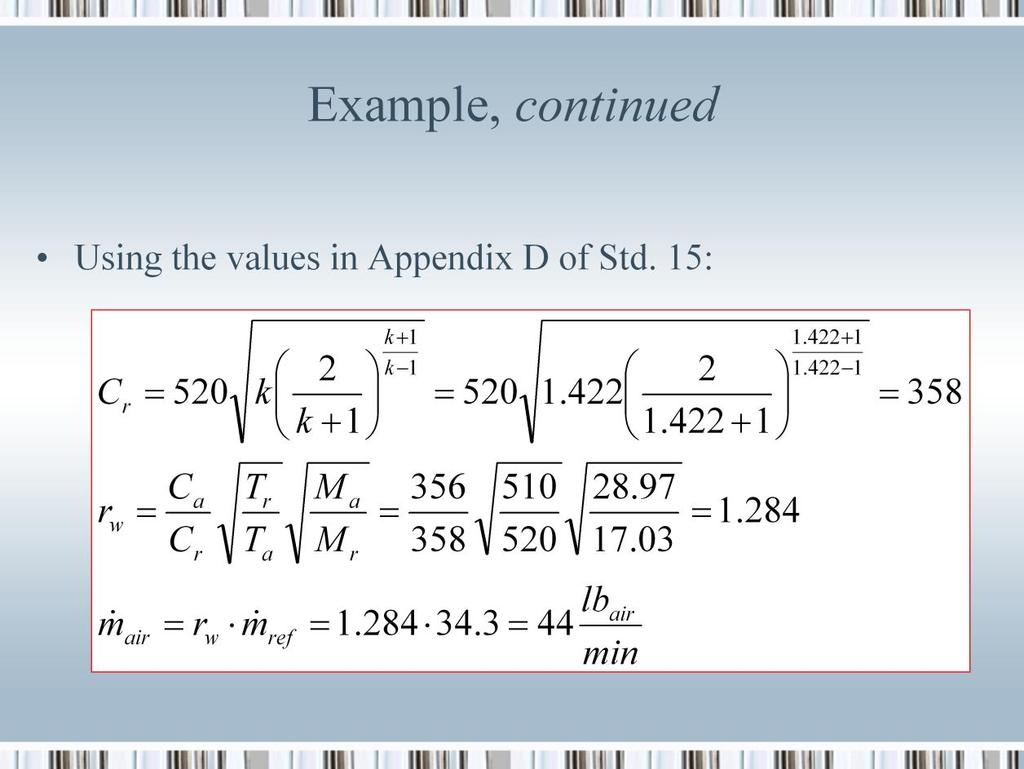
 r w is the refrigerant-to-standard-air-mass-flow conversion factor M a is the molar mass of air = 28.")
5 where: k is the ratio of specific heats for refrigerant vapor evaluated at the fully accumulated set pressure C r is a constant for the refrigerant vapor C a is a constant for air (356 ASHRAE Appendix D) r w is the refrigerant-to-standard-air-mass-flow conversion factor M a is the molar mass of air = M r is the molar mass of refrigerant T a is the absolute temperature of the air (ASHRAE Appendix D T a = 520 R) T r is the absolute temperature of the refrigerant at the relieving condition (ASHRAE Appendix D assumes T r = 520 R) IRC 2011 All Rights Reserved 5
![Where: GPM = minimum required volumetric flow rate of liquid (refrigerant) to accommodate the volume expansion [gal/min] H = heat addition [Btu/hr] B = refrigerant volumetric coefficient of](/docs-images/76/73055101/images/6-0.jpg "expansion [1/ F] c p = liquid refrigerant specific heat [Btu/lb m -F] S = refrigerant specific gravity (density of the refrigerant relative to water at 62.")
6 Where: GPM = minimum required volumetric flow rate of liquid (refrigerant) to accommodate the volume expansion [gal/min] H = heat addition [Btu/hr] B = refrigerant volumetric coefficient of expansion [1/ F] c p = liquid refrigerant specific heat [Btu/lb m -F] S = refrigerant specific gravity (density of the refrigerant relative to water at 62.4 lb m /ft 3 ) IRC 2011 All Rights Reserved 6
 D = vessel diameter (ft) L = vessel length (ft) IRC 2011 All")
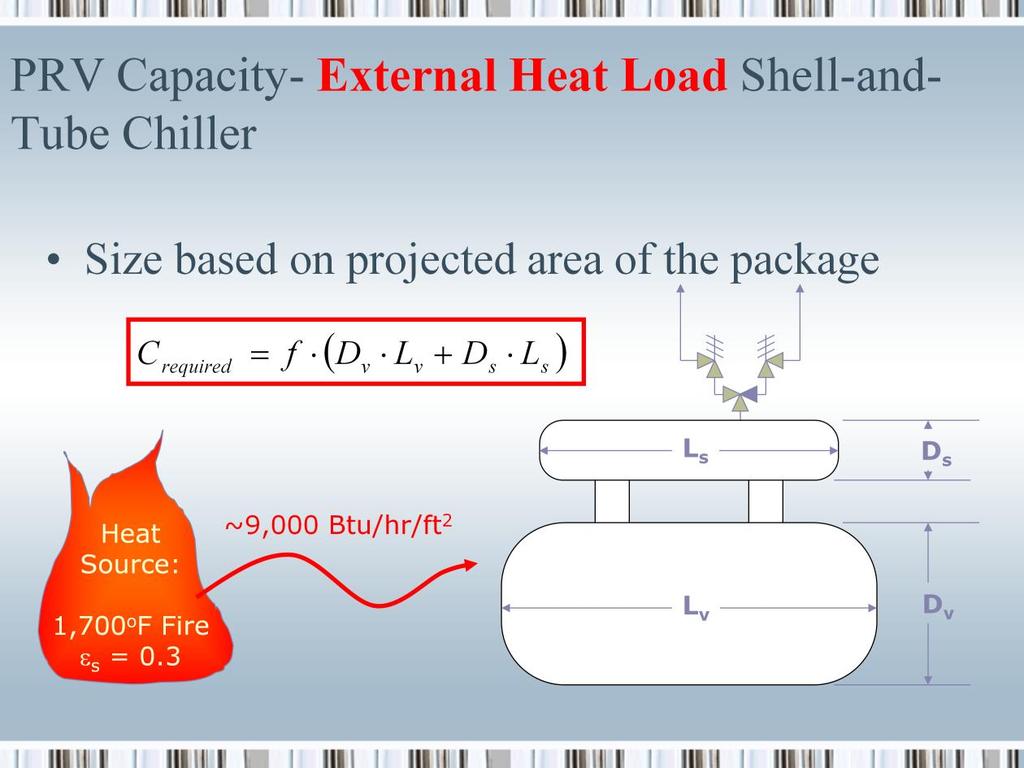
7 where: C required = minimum required relief device discharge capacity rate (lb air /min) f = for ammonia f = 0.5 or f=1.25 if combustible materials are within 20 ft of protected device) D = vessel diameter (ft) L = vessel length (ft) IRC 2011 All Rights Reserved 7
8 8
9 Per ASHRAE : 9.8 Positive Displacement Compressor Protection. Every positive displacement compressor with a stop valve in the discharge connection shall be equipped with a pressure-relief device of adequate size and pressure setting, as specified by the compressor manufacturer, to prevent rupture of the compressor or to prevent the pressure from increasing to more than 10% above the maximum allowable working pressure of any other component located in the discharge line between the compressor and the stop valve or in accordance with Section 9.7.5, whichever is larger. The pressure-relief device shall discharge into the low-pressure side of the system or in accordance with Section Exception: Hermetic refrigerant motor-compressors that are listed and have a displacement less than or equal to 50 ft 3 /min (1.42 m 3 /min). The relief device(s) shall be sized based on compressor flow at the following conditions: 1. Compressors in Single-Stage Systems and High-Stage Compressors of Other Systems: Flow shall be calculated based on 50 F (10 C) saturated suction temperature at the compressor suction. 2. Low-Stage or Booster Compressors in Compound Systems: For those compressors that are capable of running only when discharging to the suction of a IRC 2011 All Rights Reserved 9
10 high-stage compressor, flow shall be calculated based on the saturated suction temperature equal to the design operating intermediate temperature. 3. Low-Stage Compressors in Cascade Systems: For those compressors that are located in the lower-temperature stage(s) of cascade systems, flow shall be calculated based on the suction pressure being equal to the pressure setpoint of the pressure-relieving devices that protect the lowside of the stage against overpressure. Exception for items 1, 2, and 3: The discharge capacity of the relief device is allowed to be the minimum regulated flow rate of the compressor when the following conditions are met: a. the compressor is equipped with capacity regulation, b. capacity regulation actuates to minimum flow at 90% of the pressurerelief device setting, and c. a pressure-limiting device is installed and set in accordance with the requirements of Section 9.9. Informative Appendix D describes one acceptable method of calculating the discharge capacity of positive displacement compressor relief devices Pressure vessels shall be protected in accordance with Section 9.7. Pressurerelief devices are acceptable if they either bear a nameplate or are directly marked with a UV or VR symbol signifying compliance with Section VIII of the ASME Boiler and Pressure Vessel Code. IRC 2011 All Rights Reserved 9

11 An example is done in ASHRAE Appendix D IRC 2011 All Rights Reserved 10
12 9.9 Pressure-Limiting Devices When Required. Pressure-limiting devices shall be provided on all systems operating above atmospheric pressure, except that a pressure-limiting device is not required on any factory-sealed system containing less than 22 lb (10 kg) of Group A1 refrigerant that has been listed by an approved, nationally recognized testing laboratory and is so identified Setting. When required by 9.9.1, the maximum setting to which a pressure-limiting device is capable of being readily set by use of the adjusting means provided shall not exceed the design pressure of the high-side of a system that is not protected by a pressure-relief device or 90% of the setting of the pressure-relief device installed on the high-side of a system. The pressure-limiting device shall stop the action of the pressureimposing element at a pressure no higher than this maximum setting. Exception: On systems using non-positive displacement compressors, the maximum setting of the pressure limiting device is not required to be less than the design pressure of the high-side of the system provided the pressure-relief device is (1) located in the low-side and (2) subject to low-side pressure and (3) there is a permanent (un-valved) relief path between the high-side and the low-side of the system Connection. Pressure-limiting devices shall be connected between the pressure-imposing element and any stop valve on the discharge side. There shall be no intervening stop valves in the line leading to the pressurelimiting device. IRC 2011 All Rights Reserved 11
13 12
14 13
15 14
16 15

17 Note that the example in ASHRAE Appendix D uses a refrigerant temperature of 50 o F (510 o R) for the analysis. Another possibility that may be more reflective of the actual conditions would be to establish the mass flow conversion based on a saturation temperature at the relieving pressure of 275 psig (250 psig set pressure plus 10% overpressure), which for ammonia at sea level atmospheric pressure of 14.7 psia is approximately 20 o F. This change makes the multiplier instead of IRC 2011 All Rights Reserved 16
18 17
19 18
20 19

21 C r,plate,hx = minimum required discharge capacity of relief devices (lb m /min of air) f = a factor that depends on the type of refrigerant and whether or not there are combustible materials within 20 ft of the pressure vessel. For ammonia, f=0.5 when no combustible materials are within 20 ft of the vessel and f=1.25 when combustible materials are located within 20 ft of the vessel. L = length of the plate pack (ft) W = width of the plate pack (ft) H = height of the plate pack (ft) IRC 2011 All Rights Reserved 20
22 IIAR states: The required discharge capacity of a pressure relief device for each pressure vessel shall be determined by the following equation: C = 0.5 DL (lb/min) [C = 0.04 DL [kg/s]] where C = required discharge capacity of the relief device, lb air/min [kg/s] D = outside diameter of vessel, ft [m] L = length of vessel, ft [m]. When one pressure relief device is used to protect more than one pressure vessel, the required capacity shall be the sum of the capacities required for each pressure vessel. In the case of a plate heat exchanger, replace the DxL portion of the equation with a term equal to half the overall external surface area in square feet (m 2 ). In the case of a double-pipe condenser, replace the DxL portion of the equation with a term equal to half the overall external surface area in square feet (m 2 ). NOTES: a. When combustible materials are used within 20 ft (6.1 m) of a pressure vessel, the formula becomes C = 1.25 DL [C = 0.1 DL]. b. The formula is based on fire conditions. Other heat sources shall be calculated separately. IRC 2011 All Rights Reserved 21
23 22
 T sat,ref = Saturation temperature of refrigerant evaluated at the fully accumulated relief device set pressure P = P set * 1.1 + 14.")
24 Where: A = area for heat transfer (ft 2 ) U = overall heat transfer coefficient from the refrigerant to process fluid (Btu/hr-ft 2 - F) T CIP = Temperature of fluid creating potential overpressure situation during internal load scenario ( F) T sat,ref = Saturation temperature of refrigerant evaluated at the fully accumulated relief device set pressure P = P set * , ( F) h vapor = Enthalpy of saturated vapor at the fully accumulated relief device set pressure, (Btu/lb m ) h liquid = Enthalpy of saturated liquid at the fully accumulated relief device set pressure, (Btu/lb m ) IRC 2011 All Rights Reserved 23
25 The conversion from ammonia to an air basis mass flow rate is based on the following air properties: C a = 356 T a = 520 R M a = and the following ammonia properties: P = psia (250* ) Dh = 488 Btu/lb m k = T r = R (120.8 F saturation temperature at psia) IRC 2011 All Rights Reserved 24
 Dh = 488 Btu/lb m k = 1.575 T r = 580.8 R (120.8 F saturation temperature at 289.")
26 The conversion from ammonia to an air basis mass flow rate is based on the following air properties: C a = 356 T a = 520 R M a = and the following ammonia properties: P = psia (250* ) Dh = 488 Btu/lb m k = T r = R (120.8 F saturation temperature at psia) IRC 2011 All Rights Reserved 25
27 26
28 27
29 Q OC,max T suction = design heat load on the oil cooling heat exchanger (Btu/min) = saturated suction temperature ( F) m refr,ts = mass flow rate of refrigerant vapor produced by the oil cooler at maximum heat load (lb m /min) h vapor = saturated vapor refrigerant enthalpy at the fully accumulated relief device set pressure P=P set * , (Btu/lb m ) h liquid = saturated liquid refrigerant enthalpy at the fully accumulated relief device set pressure P=P set * 1.1 _ 14.7, (Btu/lb m ) IRC 2011 All Rights Reserved 28
30 29
31 30
ASHRAE made significant changes in 2001 to the calculations. Fundamentals of Safety Relief Systems
 2008, American Society of Heating, Refrigerating and Air-Conditioning Engineers, Inc. (www.ashrae.org). Published in ASHRAE Journal, Vol. 50, February 2008. This posting is by permission of ASHRAE. Additional
Single & Headered Relief Vent Piping Analysis
 Single & Headered Relief Vent Piping Analysis Todd Jekel, Ph.D., P.E. Industrial Refrigeration Consortium 2005 Research & Technology Forum January 21, 2005 Madison, WI 1 Purpose Vent piping requirements
Equipment, Design, and Installation of Closed-Circuit Ammonia Mechanical Refrigerating Systems
 American National Standard For ANSI/IIAR -1999, Addendum A-005 Equipment, Design, and Installation of Closed-Circuit Ammonia Mechanical Refrigerating Systems Approved by the American National Standards
DISCLAIMER OF WARRANTIES AND LIMITATION OF LIABILITIES
 DISCLAIMER OF WARRANTIES AND LIMITATION OF LIABILITIES THIS REPORT WAS PREPARED BY THE ORGANIZATION(S) NAMED BELOW. NEITHRE THE ORGANIZATION(S) BELOW, NOR ANY PERSON ACTING ON BEHALF OF THEM: (A) MAKES
Technical Committee on LP-Gas at Utility Gas Plants
 Technical Committee on LP-Gas at Utility Gas Plants Addendum to the Agenda Sheraton Denver Downtown 1550 Court Place Denver, CO 80202 August 7-8, 2013 The following items relate to item 5.B of the Agenda:
The Electronic Newsletter of The Industrial Refrigeration Consortium
 The Electronic Newsletter of The Industrial Refrigeration Consortium RELIEF VALVES 101 Vol. 6 No. 1, 2006 In this issue of the Cold Front, we present a basic overview of pressure relief valves their purpose,
Case 12 Multistage Centrifugal Refrigeration System Halocarbon Refrigerant
 Case 12 Multistage Centrifugal Refrigeration System Halocarbon Refrigerant Copy Right By: Thomas T.S. Wan 温 ) April 15, 2011 All Rights Reserved Case Background: This case is to show how to achieve the
Practical Guide. By Steven T. Taylor, P.E., Member ASHRAE
 ractical Guide The following article was published in ASHRAE Journal, March 2003. Copyright 2003 American Society of Heating, Refrigerating and Air- Conditioning Engineers, Inc. It is presented for educational
The capacity of the cargo tank venting system (46 CFR );
;") INDUSTRY GUIDELINES FOR DETERMINING THE MAXIMUM LIQUID TRANSFER RATE FOR A TANK VESSEL TRANSFERRING A FLAMMABLE OR COMBUSTIBLE CARGO USING A VAPOR CONTROL SYSTEM This document provides guidance from the
INDUSTRY GUIDELINES FOR DETERMINING THE MAXIMUM LIQUID TRANSFER RATE FOR A TANK VESSEL TRANSFERRING A FLAMMABLE OR COMBUSTIBLE CARGO USING A VAPOR CONTROL SYSTEM This document provides guidance from the
Pressure-Relief Valves
 HVCR PRODUCTS Superior offers the most complete range of refrigeration relief valves in the industry. ll valves have been designed, constructed and rated in accordance with NSI/SHRE 5-994 Standard Safety
Specifications, Applications, Service Instructions & Parts EZ-SRV CARTRIDGE PRESSURE-RELIEF VALVES. For Ammonia and Halocarbon Refrigeration Systems
 Cat. Air I n l e t O u t l e t Bulletin SEP 211 Specifications, Applications, Service Instructions & Parts EZ-SRV CARTRIDGE PRESSURE-RELIEF VALVES For Ammonia and Halocarbon Refrigeration Systems EZ-SRV
HANDBOOK SAFETY DEVICES. Ed SAFETY DEVICES DS-ED 01/ ENG 1
 HANDBOOK Ed. 2017 1 CHAPTER 5 SELECTION CRITERIA FOR SAFETY VALVES CALCULATION OF THE DISCHARGE CAPACITY (Ref. EN 13136:2013) The evaluation of the minimum required discharge capacity of safety valves
Seminar 65 Compression Challenges for Low GWP Refrigerants
 Margaret Mathison, Ph.D. mm1@iastate.edu Seminar 65 Compression Challenges for Low GWP Refrigerants Design Improvements of the Spool Compressor for Various Working Fluids using Comprehensive Modeling Techniques
ACFM vs. SCFM vs. ICFM Series of Technical White Papers from Squire-Cogswell
 ACFM vs. SCFM vs. ICFM Series of Technical White Papers from Squire-Cogswell Squire Cogswell / Aeros Instruments, Inc. 1111 Lakeside Drive Gurnee, IL 60031 Phone: (800) 448-0770 Fax: (847) 855-6304 info@squire-cogswell.com
SELECTION CRITERIA FOR SAFETY VALVE
 mdmdmdpag 1 di 17 SELECTION CRITERIA FOR SAFETY VALVE CALCULATION OF THE DISCHARGE CAPACITY (Ref. EN 13136:2013) The calculation of the minimum discharge capacity is linked to the system configuration
PROPERTIES OF R-134A (1,1,1,2-TETRAFLUOROETHANE)
") PROPERTIES OF R-134A (1,1,1,2-TETRAFLUOROETHANE) Industrial Refrigeration Consortium University of Wisconsin Madison, WI USA Who we Are The IRC is a collaborative effort between the University of Wisconsin-Madison
PROPERTIES OF R-134A (1,1,1,2-TETRAFLUOROETHANE) Industrial Refrigeration Consortium University of Wisconsin Madison, WI USA Who we Are The IRC is a collaborative effort between the University of Wisconsin-Madison
The Hoffman Specialty Series 2000 consists of main
 Pressure and/or Temperature Pilot Operated Steam Series 2000 The Hoffman Specialty Series 2000 consists of main valves, pilot valves, wells and hardware kits. They are designed to meet a wide range of
Application Worksheet
 Application Worksheet All dimensions are nominal. Dimensions in [ ] are in millimeters. Service Conditions Medium Through Valve: Required C v : Temperature Maximum: Minimum: Normal: Flow Maximum: Minimum:
POP Safety Valve. POP Safety Valve INTRODUCTION DEFINITIONS
 POP Safety Valve POP Safety Valve INTRODUCTION The effects of exceeding safe pressure levels in an unprotected pressure vessel or system, can have catastrophic effects on both plant and personnel. Safety
HANDBOOK SAFETY DEVICES. Ed SAFETY DEVICES DS-ED 01/ ENG 1
 HANDBOOK Ed. 2017 DS-ED 01/2017 - ENG 1 CHAPTER 9 BURSTING DISC DEVICES IN SERIES 3070 SCOPE Use: protection against possible overpressure of the apparatuses listed below, with regard to the operating
MAKING MODERN LIVING POSSIBLE. Pilot operated internal safety valves type POV REFRIGERATION AND AIR CONDITIONING DIVISION.
 MAKING MODERN LIVING POSSIBLE Pilot operated internal safety valves type POV REFRIGERATION AND AIR CONDITIONING DIVISION Technical leaflet Contents Page Introduction...3 Features...3 Design...4 Technical
RELIEF VALVES & RELEASES
 The Electronic Newsletter of The Industrial Refrigeration Consortium Vol. 6 No. 2, 2006 RELIEF VALVES & RELEASES In this issue of the Cold Front, we discuss proper termination of pressure relief vents
The Discussion of this exercise covers the following points: Pumps Basic operation of a liquid pump Types of liquid pumps The centrifugal pump.
 Exercise 2-3 Centrifugal Pumps EXERCISE OBJECTIVE In this exercise, you will become familiar with the operation of a centrifugal pump and read its performance chart. You will also observe the effect that
System Conditions Harmful to Compressors Their Diagnosis and Prevention
 Purdue University Purdue e-pubs International Compressor Engineering Conference School of Mechanical Engineering 1972 System Conditions Harmful to Compressors Their Diagnosis and Prevention M. A. Ramsey
Natural Gas Gathering
 Natural Gas Gathering Course No: R04-002 Credit: 4 PDH Jim Piter, P.E. Continuing Education and Development, Inc. 9 Greyridge Farm Court Stony Point, NY 10980 P: (877) 322-5800 F: (877) 322-4774 info@cedengineering.com
Type R622 Pressure Reducing Regulator
 Type R622 Pressure Reducing Regulator June 2010 Compact Design Protective Inlet Screen High Capacity Internal Relief Light Weight W8806 Inlet and Outlet Pressure Gauge Taps Figure 1. Type R622 Pressure
44 (0) E:
 E:") FluidFlow Relief Valve Sizing Handbook Flite Software 2016 Flite Software N.I. Ltd, Block E, Balliniska Business Park, Springtown Rd, Derry, BT48 0LY, N. Ireland. T: 44 (0) 2871 279227 E: sales@fluidflowinfo.com
FluidFlow Relief Valve Sizing Handbook Flite Software 2016 Flite Software N.I. Ltd, Block E, Balliniska Business Park, Springtown Rd, Derry, BT48 0LY, N. Ireland. T: 44 (0) 2871 279227 E: sales@fluidflowinfo.com
Two-Stage Linear Compressor with Economizer Cycle Where Piston(s) Stroke(s) are Varied to Optimize Energy Efficiency
 Stroke(s) are Varied to Optimize Energy Efficiency") Purdue University Purdue e-pubs International Compressor Engineering Conference School of Mechanical Engineering 2006 Two-Stage Linear Compressor with Economizer Cycle Where Piston(s) Stroke(s) are Varied
Purdue University Purdue e-pubs International Compressor Engineering Conference School of Mechanical Engineering 2006 Two-Stage Linear Compressor with Economizer Cycle Where Piston(s) Stroke(s) are Varied
Dimensioning of Safety Valves Auditorium Tecnimont
 Dimensioning of Safety Valves Auditorium Tecnimont 21.09.2016 Objective of the presentation Design of Safety Valves ASME VIII / API 520 The objective of the presentation is to show the design of safety
Single- or Two-Stage Compression
 The following article was published in ASHRAE Journal, August 2008. Copyright 2008 American Society of Heating, Refrigerating and Air- Conditioning Engineers, Inc. It is presented for educational purposes
GLOSSARY OF TERMS. Adiabatic Compression Compression process when all heat of compression is retained in the gas being compressed.
 GLOSSARY OF TERMS Absolute pressure Total pressure measured from absolute zero i.e. a perfect vacuum. As a practical matter, gauge pressure plus atmospheric pressure. Absolute temperature Temperature measured
Si C132. Safety valves for pressure relief in accordance to PED, DIN/EN and ASME. Engineering GREAT Solutions
 Safety valves for pressure relief in accordance to PED, DIN/EN and ASME Engineering GREAT Solutions Si C132 Features The universal compact safety valve > 3 body seat sizes for appropriate size selection
plumbing SAFETY AND RELIEF VALVES PART II
 BY BOB VILLENEUVE SAFETY AND RELIEF VALVES PART II In Safety and Relief Valves Part I in HPAC Magazine s May/June 2005 issue, the terms, definitions and regulations related to safety relief valves were
COMMITTEE DRAFT. API 520 Part I 10 th Edition Ballot Item 2.1. This ballot covers the following item:
 This ballot covers the following item: API 520 Part I 10 th Edition Ballot Item 2.1 2008 12 Modify guidance to PRV datasheets (Line 17) to assist user s with determining the temperature to use for selecting
SERIES SAFETY VALVE
 R Manufactured by Conbraco Industries, Inc. 10-600 SERIES SAFETY VALVE INSTALLATION, OPERATION, & MAINTENANCE Part I Document Number: ES-1325 Revision Level: B Issued By: T.HAMILTON Date: 3/3/16 Approved
Limited quantities of compressed gases.
 173.306 Limited quantities of compressed gases. (a) Limited quantities of compressed gases for which exceptions are permitted as noted by reference to this section in 172.101 of this subchapter are excepted
What is pressure relief valve? Pressure relief valve
 What is pressure relief valve? Pressure relief valve What is: Relief valve Safety valve Safety relief valve Type of pressure relief valve Pressure relief valve sizing base What are the sizing basis of
The Application of Temperature and/or Pressure Correction Factors in Gas Measurement
 The Application of Temperature and/or Pressure Correction Factors in Gas Measurement COMBINED BOYLE S CHARLES GAS LAWS To convert measured volume at metered pressure and temperature to selling volume at
Analytic and Experimental Techniques for Evaluating Compressor Performance Losses
 Purdue University Purdue e-pubs International Compressor Engineering Conference School of Mechanical Engineering 1976 Analytic and Experimental Techniques for Evaluating Compressor Performance Losses J.
29 SERIES - SAFETY VALVE
 INDUSTRIES, INC. 29 SERIES - SAFETY VALVE INSTALLATION, OPERATION, & MAINTENANCE Part I Document Number: ES1016-1 Revision Level: A Issued By: David Edmonds Date: 6/20/04 Approved By: Date: 10/4/04 Conbraco
North American 7339 High Pressure Gas Regulators
 Combustion North American 7339 High Pressure Gas Regulators Bulletin 7339 7339 Regulators reduce high gas supply pressures to practical use levels. Since capacities will vary with the pressure drop across
SG TF. Q = 963 Cv (P1 - P2)(P1 + P2) TECHNICAL INFORMATION. Flow Q (GPM)
(P1 + P2) TECHNICAL INFORMATION. Flow Q (GPM)") TECHNICAL INFORMATION BuTech designs all pressure-containing equipment to meet or exceed the applicable requirements of Section VIII, Division1 or Division 2 of the ASME Boiler and Pressure Vessel Code
TECHNICAL INFORMATION BuTech designs all pressure-containing equipment to meet or exceed the applicable requirements of Section VIII, Division1 or Division 2 of the ASME Boiler and Pressure Vessel Code
Exercise 4-2. Centrifugal Pumps EXERCISE OBJECTIVE DISCUSSION OUTLINE DISCUSSION. Pumps
 Exercise 4-2 Centrifugal Pumps EXERCISE OBJECTIVE Familiarize yourself with the basics of liquid pumps, specifically with the basics of centrifugal pumps. DISCUSSION OUTLINE The Discussion of this exercise
ASSIGNMENT 2 CHE 3473
 DUE: May 23 ASSIGNMENT 2 CHE 3473 #Problem 1: 3.3 #Problem 2: 3.4 #Problem 3: 3.5 #Problem 4: 3.6 #Problem 5: 3.7 #Problem 6: 3.8 #Problem 7: 3.11 #Problem 8: 3.15 #Problem 9: 3.22 #Problem 10: 3.32 #Problem
ASSIGNMENT 2 CHE 3473
 DUE: May 21 ASSIGNMENT 2 CHE 3473 #Problem 1 Read Chapter 3. ALL OF IT. Time yourself and report the time. #Problem 2: 3.2 #Problem 3: 3.3 #Problem 4: 3.5 #Problem 5: 3.6 #Problem 6: 3.7 #Problem 7: 3.8
PROCEDURES FOR REPAIRS TO ASME NV STAMPED PRESSURE RELIEF DEVICES OF NUCLEAR SAFETY RELATED PRESSURE RELIEF VALVES
 NB16 0603 NR Task Group 1 9 16 1. One update by NR task group page 3: 7/17/19 2. Two updates to S6.1 and S6.3 on page 1: 7/19/17 SUPPLEMENT 6 PROCEDURES FOR REPAIRS TO ASME NV STAMPED PRESSURE RELIEF DEVICES
****** * EX * ****** DWN W.W.POWELL CALCULATION OF FLOW LOSSES IN INLET CHK D.PAPA AND DISCHARGE HEADERS ASSOCIATED WITH
 BC ****** * EX * ****** DWN W.W.POWELL 4-17-75 CALCULATION OF FLOW LOSSES IN INLET CHK D.PAPA 4-17-75 AND DISCHARGE HEADERS ASSOCIATED WITH APPR APPR SAFETY RELIEF VALVES SIZE REV APPR A 02.0175.128 L
ASME CODE EXCERPTS FROM
 - 71 - NOTES: - 72 - SECTION I SECTION I - 73 - NOTES: SECTION I - 74 - ASME SECTION I PG-67.1 PART PG GENERAL REQUIREMENTS PG-67.4.1 SAFETY VALVES AND SAFETY RELIEF VALVES 16 PG-67.2.3 The minimum required
Advanced Management of Compressed Air Systems Pre-Workshop Assignment
 Advanced Management of Compressed Air Systems Page 1 In order to ensure that the Compressed Air Challenge Level II Training is most useful to you, it will be important for you to bring information about
CP200 Series Commercial / Industrial Pressure- Loaded Pressure Reducing Regulator
 CP200 Series Commercial / Industrial Pressure- Loaded Pressure Reducing Regulator May 2010 Figure 1. CP200 Series Pressure Loaded Regulator Features and Benefits Wide Range of NPT Body Sizes Easy to Install
BASICS OF RELIEF VALVES
 BASICS OF RELIEF VALVES Parts Nozzle - The pressure containing element which constitutes the inlet flow passage and includes the fixed portion of the seat closure. The nozzle can be of two designs: Full-nozzle
Quiz #1 Thermodynamics Spring, 2018 Closed Book, Open Appendices, Closed Notes, CLOSED CALCULATORS
 Quiz #1 Closed Book, Open Appendices, Closed Notes, CLOSED CALCULATORS An astronaut has a mass of 161 lbm on the surface of the earth. Calculate his weight (in lbf) on planet Rigel 4 where g = 20.0 ft/s
ENGINEERING FLUID MECHANICS
 DEPARTMENT of MECHANICAL ENGINEERING FLUID MECHANICS Subject code: 10ME46B Faculty name: Naveen H E QUESTION BANK UNIT-1: FLUID PROPERTIES 1. Define the following: i) density, ii) weight density, iii)
CHAPTER 3 : AIR COMPRESSOR
 CHAPTER 3 : AIR COMPRESSOR Robotic & Automation Department FACULTY OF MANUFACTURING ENGINEERING, UTeM Learning Objectives Identify types of compressors available Calculate air capacity rating of compressor
API Standard Venting Atmospheric and Low-Pressure Storage Tanks: Nonrefrigerated and Refrigerated
 General API Standard 2000 - Venting Atmospheric and Low-Pressure Storage Tanks: Is there any limit for the maximum allowable linear velocity or any other parameter for the roof of a floating roof tank
PTF4 Pivotrol Pump (patented) version Dual Mechanism - Pressure Powered Pump
 version Dual Mechanism - Pressure Powered Pump") Local regulations may restrict the use of this product to below the conditions quoted. In the interests of development and improvement of the product, we reserve the right to change the specification without
Local regulations may restrict the use of this product to below the conditions quoted. In the interests of development and improvement of the product, we reserve the right to change the specification without
Challenges in Relief Design for Pilot Plants
 Challenges in Relief Design for Pilot Plants Published on July 5, 2017 Michael Trainor Relief system design at the pilot scale presents unique challenges that don t always apply at the commercial scale.
776 Cryogenic Safety Valve
 776 Cryogenic Safety Valve INTRODUCTION 776 Cryogenic Safety Valve The effects of exceeding safe pressure levels in an unprotected pressure vessel or system, can have catastrophic effects on both plant
ARI-SAFE-SN ANSI Safety valve ANSI - safety valve Semi Nozzle (ANSI )
") ARI-SAFE-SN ANSI Safety valve ANSI - safety valve Semi Nozzle (ANSI 150-300) ARI-SAFE-SN ANSI (Semi-Nozzle) ANSI-Safety Relief Valve Type-test approved acc. to ASME Code Section VIII-Division 1. UV-stamp
ARI-SAFE-SN ANSI Safety valve ANSI - safety valve Semi Nozzle (ANSI 150-300) ARI-SAFE-SN ANSI (Semi-Nozzle) ANSI-Safety Relief Valve Type-test approved acc. to ASME Code Section VIII-Division 1. UV-stamp
Technical data. Back pressure limit: 27.5% of set pressure. Capacity certification: ASME Boiler & Pressure Vessel Code Section I and VIII
 VALVES & CONTROLS CROSBY SAFETY VALVES H ig h C a p a c it y, S t e a m S e r v ic e, F la n g e d S t e e l S a f e t y V a lv e Introduction Crosby Style HSL is a full nozzle reaction type safety valve
Expansion Tank Design (Chilled Water)
") Expansion Tank Design (Chilled Water) Table of Contents 1.0 Introduction... 2 1.1 Units... 2 2.0 Disclaimer... 2 3.0 Expansion Tank Types... 2 3.1 Open Tank... 2 3.2 Closed Tank with No Bladder... 3 3.3
Expansion Tank Design (Chilled Water) Table of Contents 1.0 Introduction... 2 1.1 Units... 2 2.0 Disclaimer... 2 3.0 Expansion Tank Types... 2 3.1 Open Tank... 2 3.2 Closed Tank with No Bladder... 3 3.3
PRESSURE RELIEF DEVICES. Table of Contents
 FM Global Property Loss Prevention Data Sheets 12-43 October 2013 Page 1 of 13 PRESSURE RELIEF DEVICES Table of Contents Page 1.0 SCOPE... 2 1.1 Changes... 2 1.2 Superseded Information... 2 2.0 LOSS PREVENTION
PRO-50 Instrument Supply Regulator
 Features CRN Approved The PRO-50 Regulator has been granted a Canadian Registration Number. Sour Service Capability Available in NACE configurations that comply with NACE MR0175/MR0103. Environmental limits
Brazed Heat Exchangers
 Brazed Heat Exchangers The Brazed Heat Exchanger less is more The brazed plate heat exchanger is the most compact heat exchanger on the market today. Its high heat transfer efficiency in combination with
Control Valve Sizing. Sizing & Selection 3 P 1. P 2 (Outlet Pressure) P V P VC. CONTENTS Introduction Nomenclature Calculating C v
 P V P VC. CONTENTS Introduction Nomenclature Calculating C v") Sizing & Selection 3 Control Valve Sizing CONTENTS Introduction 3-1 Nomenclature 3-1 Calculating for Liquids 3-3 Liquid Sizing Examples 3-7 Calculating for Gases 3-10 Gas Sizing Examples 3-13 Calculating
Sizing & Selection 3 Control Valve Sizing CONTENTS Introduction 3-1 Nomenclature 3-1 Calculating for Liquids 3-3 Liquid Sizing Examples 3-7 Calculating for Gases 3-10 Gas Sizing Examples 3-13 Calculating
MSC Guidelines for Refrigeration Machinery
 Procedure Number E1-32 Revision Date: 07/27/10 S. J. Kelly, CDR, Chief of Engineering Division References: a. 46 CFR Part 56.50-105 Low Temperature Piping b. 46 CFR Part 58.20 Refrigeration Machinery c.
T208VR Series Tank Blanketing Vacuum Regulator
 February 2014 T208VR Series Tank Blanketing Vacuum Regulator Figure 1. Typical T208VR Series Vacuum Regulator Introduction The T208VR Series direct-operated vacuum regulators are used where a decrease
Noth American 7347 High Pressure Gas Regulators
 Combustion Noth American 7347 High Pressure Gas s Bulletin 7347 7347 s reduce high gas supply pressures to practical use levels. Since capacities will vary with the pressure drop across the regulator (see
COMMERCIAL REFRIGERATION SYSTEMS WITH CO 2 AS REFRIGERANT
 COMMERCIAL REFRIGERATION SYSTEMS WITH CO 2 AS REFRIGERANT O. JAVERSCHEK Bitzer Kuehlmaschinenbau GmbH, Eschenbrünnlestr.15, 71083 Sindelfingen, Germany +49.(0)7031.9325244, javerschek@bitzer.de ABSTRACT
Electric regulating valves Type CCMT 2 - CCMT 8 / CCMT 16 - CCMT 42
 Data sheet Electric regulating valves Type CCMT 2 - CCMT 8 / CCMT 16 - CCMT 42 The CCMT is an electrically operated valve designed specifically for operation in CO 2 systems. The CCMT valve concept is
Updated Performance and Operating Characteristics of a Novel Rotating Spool Compressor
 Updated Performance and Operating Characteristics of a Novel Rotating Spool Compressor Joe Orosz Torad Engineering Cumming, Georgia Craig R. Bradshaw, PhD Torad Engineering LLC Cumming, Georgia Greg Kemp
Water valve Type WVO. Data sheet MAKING MODERN LIVING POSSIBLE
 MAKING MODERN LIVING POSSIBLE Data sheet Water valve Type WVO Water valve type WVO is used for regulating the flow of water in refrigeration plant with water-cooled condensers. The water valve gives modulating
Quick Reference Technical Data
 Bulletin 127C 2 Quick Reference Technical Data For over 100 years, The Spencer Turbine Company has specialized in innovative solutions to air and gas handling problems. Spencer's product line includes
Types 1808 and 1808A Pilot-Operated Relief Valves or Backpressure Regulators
 Types 1808 and 1808A Pilot-Operated Relief Valves or Backpressure Regulators July 2010 W3716 W3507 Type 1808 Type 1808A Figure 1. Types 1808 and 1808A Pilot-Operated Relief Valves or Backpressure Regulators
Pressure Relief Valves
 Pressure Relief Valves ANDERSON GREENWOOD flow control Contents Pressure Relief Valves Pressure Relief Valve Revised May 1998 Catalog: PRVTM-US.97 Note 1. Some referenced figures, tables, equations, or
An Investigation of Liquid Injection in Refrigeration Screw Compressors
 An Investigation of Liquid Injection in Refrigeration Screw Compressors Nikola Stosic, Ahmed Kovacevic and Ian K. Smith Centre for Positive Displacement Compressor Technology, City University, London EC1V
KNOWN: Mass, pressure, temperature, and specific volume of water vapor.
 .0 The specific volume of 5 kg of water vapor at.5 MPa, 440 o C is 0.60 m /kg. Determine (a) the volume, in m, occupied by the water vapor, (b) the amount of water vapor present, in gram moles, and (c)
S.A. Klein and G.F. Nellis Cambridge University Press, 2011
 16-1 A flow nozzle is to be used to determine the mass flow rate of air through a 1.5 inch internal diameter pipe. The air in the line upstream of the meters is at 70 F and 95 psig. The barometric pressure
Type EZH Relief or Backpressure Regulator
 Bulletin 71.4 D103574X012 Type EZH December 2017 Type EZH Relief or Backpressure Regulator P1668 Figure 1. Type EZH Relief Valve or Backpressure Regulator Features Bubble Tight Shutoff A knife-edged metal
REFRIGERATION SYSTEM COMPONENTS
 REFRIGERATION SYSTEM COMPONENTS henrytech.com Conventional Oil Separators The function of an Oil Separator is to remove oil from the discharge gas and return it to the Compressor either directly or through
MSC Guidelines for Pressure Vessels
 References: a. 46 CFR Part 54 Pressure Vessels S. T. Brady, CDR, Chief, Engineering Division b. ASME Boiler and Pressure Vessel Code (BPVC), Section VIII, Division 1, (1998 Edition) c. Navigation and Inspection
Tank Blanketing Pressure Regulators RHPS Series
 www.swagelok.com Tank Blanketing Pressure Regulators RHPS Series Types: pressure reducing and vapor recovery 16L stainless steel construction 1/2, 1, and 2 in. end connections Working pressures up to 22
Tutorial. BOSfluids. Relief valve
 Tutorial Relief valve The Relief valve tutorial describes the theory and modeling process of a pressure relief valve or safety valve. It covers the algorithm BOSfluids uses to model the valve and a worked
RMP/PSM WEBINAR SERIES
 RMP/PSM WEBINAR SERIES Webinar Starts at 08:00 PT Please call (877) 532-0806 if you are having technical issues. The background music may be used to adjust your audio volume. IIAR STANDARDS AND HOW THEY
Proportional Relief Valves
 www.swagelok.com Proportional Relief Valves R Series Liquid or gas service Set pressures from 10 to 6000 psig (0.68 to 413 bar) 1/4 and 1/2 in. and 6 to 12 mm end connections 2 Proportional Relief Valves
LECTURE 20 FLOW CONTROL VAVLES SELF EVALUATION QUESTIONS AND ANSWERS
 LECTURE 20 FLOW CONTROL VAVLES SELF EVALUATION QUESTIONS AND ANSWERS 1: A cylinder has to exert a forward thrust of 150 kn and a reverse thrust of 15 kn. The effects of using various methods of regulating
AE R8 December 2004 Reformatted November Copelametic Two-Stage Compressors Application and Service Instructions
 AE19-1132 R8 December 2004 Reformatted November 2010 Copelametic Two-Stage Compressors Application and Service Instructions The Copeland two stage compressors have been developed to efficiently achieve
Relief Systems. 11/6/ Fall
 Relief Systems 1 Relief Scenarios o A single relief event requires a particulate vent area and valve size o Relief scenarios are determined based on a PHA o For each scenario, a vent area is calculated
756 Safety Relief Valves
 756 S a fe t y R e l i e f Va l ve s INTRODUCTION 756 Safety Relief Valves The effects of exceeding safe pressure levels in an unprotected pressure vessel or system, can have catastrophic effects on both
1805 Series Relief Valves
 October 2011 1805 Series Relief Valves P1026 1805G Type 1805-2 Type 1805-4 Figure 1. Typical 1805 Relief Valves Introduction The 1805 Series relief valves are designed for use in farm tap applications
Modeling a Pressure Safety Valve
 Modeling a Pressure Safety Valve Pressure Safety Valves (PSV), Pressure Relief Valves (PRV), and other pressure relieving devices offer protection against overpressure in many types of hydraulic systems.
Pump-Fan-Compressor Sizing
 Pump-Fan-Compressor Sizing Introduction This program determines the fluid transportation characteristics of dominant pipeline process systems containing no loops. In addition, it determines the yearly
ANDERSON GREENWOOD. Provides reliable overpressure protection in a cost effective package. Flow Control
 ANDERSON GREENWOOD Provides reliable overpressure protection in a cost effective package. Product Overview Anderson Greenwood s LCP Series pilot operated safety valve is designed to provide the reliable
Horizontal Bladder Tanks
 DATA SHEET Horizontal Bladder Tanks Features UL Listed and FM Approved for use with various ANSUL proportioners and foam concentrates 175 psi (12.1 bar) maximum allowable working pressure (design pressure)
INTRODUCTION TO REGULATOR AND RELIEF VALVE SIZING. Introduction
 INTRODUCTION TO REGULATOR AND RELIEF VALVE SIZING MARK DYKOFF MANAGER, GAS REGULATION AND CONTROL CALTROL, INC. Introduction Regulators used in natural gas applications are devices made up of a valve and
SAFETY MANUAL FOR FLAMMABLE PRODUCT TRANSFER
 SAFETY MANUAL FOR FLAMMABLE PRODUCT TRANSFER SUPPLIMENT TO eom IMPORTANT READ THIS MANUAL BEFORE PRODUCT INSTALLATION, OPERATION, INSPECTION & MAINTENANCE Tougher and more rigid guidelines are being established
SAMPLE RH = P 1. where. P 1 = the partial pressure of the water vapor at the dew point temperature of the mixture of dry air and water vapor
 moisture starts to condense out of the air. The temperature at which this happens is called the dew point temperature, or the saturation temperature. What is commonly called saturation pressure or condensing
2 are both ways of saying a ratio of 2 to 5
 Unit 4 Ratios A Ratio is a comparison of two related quantities. Ratios are expressed in two forms. 2 : 5 or 5 2 are both ways of saying a ratio of 2 to 5 1. Conversion factors are ratios. Express 100
Chapter 13 Gases, Vapors, Liquids, and Solids
 Chapter 13 Gases, Vapors, Liquids, and Solids Property is meaning any measurable characteristic of a substance, such as pressure, volume, or temperature, or a characteristic that can be calculated or deduced,
WATER MADE EASY MARINE ENERGY MUNICIPAL INDUSTRIAL
 Capital Controls Series 71V3000 The Series 71V3000 electrically-heated vaporizer automatically vaporizes and superheats liquid chlorine, sulfur dioxide or ammonia at a rate controlled by the gas feed system.