AirTEP Information Manual
|
|
|
- Shawn Hamilton
- 6 years ago
- Views:
Transcription
1 Capewell Aerial Systems LLC 105 Nutmeg Road South South Windsor, CT P: AirTEP Information Manual
2 AirTEP Special Forces Platform PRODUCT DESCRIPTION The Airborne Tactical Extraction Platform is specially designed for Special Forces. Planned in black the AirTEP is composed of: 1 Platform 5 Nets * 1 Rope * 10 Long Safety Belts * 1 Souding Line * 1 Mast Strap * 1 Protection Shoe (Innovation 2008) 1 Hardcase (Innovation 2008) 1 Rope bag 1 Platform Bag 1 Braking Device 1 Shackle Ratchet Folding Strap 3 Velcro Strap * Black Aramid fiber (Innovation 2008) Optional Device for centerwise dropping 1 Guiding Ring 1 BK Hook Escape International - AirTEP - Range /1
3 NATO CODIFICATION SYSTEM (NCS) NCAGE FAT21 Nat.Ident No Items of supply NIIN/NSN Industrial references 7N03775
4 CERTIFICATE OF AIRWORTHINESS Escape International 131 rue Cardinet Paris France Certificate of Airworthiness 1/2
5 Escape International certifies that the Airborne Platform, Serial number Conforms to its type design Is in a condition for safe flight Meets the requirements applicable to its specifications, defined by the : Acte technique DGA N /SPAé/ST/CEA Acte technique DGA N /SPAé/CEA Acte technique DGA N /CEP/ASA/PFA OPERATING LIMITS Max loading capacity: 1500kg with a max of 300 kg per net Standard loading is 10 people 5 additional persons can come on board if they are preequipped with safety harness fitted with a hooking device, within the limit of kg Max wind: 30 Kts Omni directional Max vertical speed on take off: 2.5 hm/min Max transit speed AIRBORNE PLATFORM CONFIGURATION MAX INDICATED SPEED Folded position LOAD 0 to 69 kg 70 to 259 kg 260 to 629 kg 630 to kg 90 km/h 80 km/h 140 km/h 180 km/h Escape International 131 rue Cardinet Paris France Certificate of Airworthiness 2/2
6 WARRANTY CERTIFICATE Escape International 131 rue Cardinet Paris France Warranty certificate 1/4
7 Escape International warrants that the Airborne platform, Serial number meets the Specifications 1 SPECIFICATIONS Dimensions Folded: height, 1.50 m; diameter, 0.40 m Opened: height 1.50 m; diameter, 2,90 m or 7 m 2 52 kg Net weight Temperature limits -30 C to +50 C Hygrometry 0 % to 100 % Operating limits Max loading capacity: 1500kg with a max of 300 kg per net Standard loading is 10 people. 5 additional persons can come on board if they are preequipped with safety harness fitted with a hooking device, within the limit of kg. Max wind: 30 Kts Omni directional Max vertical speed on take off: 2.5 hm/min Max transit speed AIRBORNE PLATFORM CONFIGURATION MAX INDICATED SPEED Folded position LOAD 0 to 69 kg 70 to 259 kg 260 to 629 kg 630 to kg 90 km/h 80 km/h 140 km/h 180 km/h Escape International 131 rue Cardinet Paris France Warranty certificate 2/4
8 2 MAINTENANCE PROTOCOL The maintenance of the Airborne Platform are made at three levels. End user level Maintenance unit level Manufacturer level At the end user level, the maintenance is defined in the maintenance manual by the monthly check-list and the check-list before usage. At this level, it is only about visual and manual checks and storage conditions to respect. Any other maintenance operation has to be excluded from this level. At the maintenance unit level The maintenance operations at this level are more complicated and required to be executed by the unit staff, trained by Escape International or the distributor, and with proper tooling. These operations are: arm replacement ratchet replacement cable replacement net replacement main lifting ring The replacement of these components can ONLY be made using spare parts supplied by Escape International. The spare parts are NOT INTERCHANGEABLE. Any maintenance operation, using non Escape spare parts, has for consequences to loose the flight qualification of the platform. The same rule applies to the accessories. At the manufacturer level AFTER CYCLES OR 5 YEARS, the platform should be return to the manufacturer for general inspection. The operations for general inspection are described pages of the maintenance manual. Using the platform beyond this limit, without having the general inspection made, leads to the lost of the flight certification of the platform and disengage the responsibility of Escape International. Escape International 131 rue Cardinet Paris France Warranty certificate 3/4
9 AFTER OR 10 YEARS, the platform should be return to the manufacturer for general inspection. The operations for general inspection are described pages of the maintenance manual. Using the platform beyond this limit, without having the general inspection made, leads to the lost of the flight certification of the platform and disengage the responsibility of Escape International. AFTER CYCLES OR 15 YEARS, a general overhaul of the platform could planed at the manufacturer premises, in regard of the shape of the platform. The cost will be estimated prior to this overhaul. Note: 1 cycle = 1 load + 1 take off + 1 flight + 1 landing 3 - GUARANTEE The platform is guaranteed for one year. This guarantee is valid for the flight specifications and under the condition that the platform is maintained in accordance with the maintenance manual and this maintenance protocol. The defective parts or accessories will be shipped by Escape International. After one year, the parts and accessories will be at the Customer charges. Escape International 131 rue Cardinet Paris France Warranty certificate 4/4
 according to GAM-EG 13 and FAR 25 procedures Inflight resistance and performance testing performed by CEV")
10 QUALIFICATION SEA KING S-61 Danish Special Operation Force Qualified Rescue Platform type A, Serial numbers 7N / Serial numbers 7N / (Fireproof) Implementation on Following SEA King S-61 Mechanical resistance testing performed by CEAT (Centre d expertise aéronautique de Toulouse) according to GAM-EG 13 and FAR 25 procedures Inflight resistance and performance testing performed by CEV (Centre d essais en vol) On year rue Cardinet Paris France Qualification Sea King 1/2
11 OPERATING LIMITS Max loading capacity: 1500 kg with a max of 300 kg per net Standard loading is 10 people 7 additional persons can come on board if they are equipped with safety harness fitted with a hooking device, within the limit of kg. This exceptional loading is limited to 50 cycles Max wind: 30 Kts Omni directional Max vertical speed on take off: 2.5 hm/min Max vertical speed on landing: Loaded: - 0,30 hm/min Unloaded: -1,5 hm/min INFLIGHT SPECIFICATIONS RESCUE PLATFORM CONFIGURATION MAX INDICATED SPEED (MIS) RATE OF LIFTING AT MIS RATE OF DESCENT AT MIS OUT OF THE LANDING PHASE MAXIMUM BASKET INCLINATION AT MIS MAXIMUM BANK ANGLE INDICATED SPEED WHEN MOVING TO THE LEFT, RIGHT AND REAR ACCELERATION STOP ENGINE FAILURE Folded position 40 kts 75 km/h 450 fpm -1,4 hm/min LOAD 0 to 70 kg 71 to 259 kg 260 to 404 kg 405 to kg 40 kts 75 km/h 450 fpm -1,4 hm/min 60 kts 110 km/h No limitation 300 fpm -1 hm/min fpm -3 hm/min 95 kts 175 km/h 30 kts (55 km/h) / aircraft limitation, whichever lowest Maximum speed of 30 kts (55 km/h) then stop Diving at 15 up to 30 kts (55km/h) then pull up 1800 fpm -5,5 hm/min ENVIRONMENTAL UTILISATION Night and day use Land use Aquatic use 131 rue Cardinet Paris France Qualification Sea King 2/2
 Implementation on SUPER FRELON Through Technical act DGA N 057-06/CEP/ASA/PFA Following Mechanical resistance testing performed by CEAT (Centre d Expertise Aéronautique")
12 QUALIFICATION SUPER FRELON DGA (Délégation Générale de l Armement) French Ministry of Defence / Aeronautical program services Qualified Rescue Platform type A, Serial numbers 7N / Serial numbers 7N / (Fireproof) Implementation on SUPER FRELON Through Technical act DGA N /CEP/ASA/PFA Following Mechanical resistance testing performed by CEAT (Centre d Expertise Aéronautique de Toulouse) according to GAM-EG 13 and FAR 25 procedures In-flight resistance and performance testing performed by CEV (Centre d Essais en Vol) The 2 nd of February rue Cardinet Paris France Qualification Super Frelon 1/2
13 OPERATING LIMITS Max loading capacity: 1500 kg with a max of 300 kg per net Standard loading is 10 people 7 additional persons can come on board if they are equipped with safety harness fitted with a hooking device, within the limit of kg. This exceptional loading is limited to 50 cycles Max wind: 30 Kts Omni directional Max vertical speed on take off: 2.5 hm/min Max vertical speed on landing: Loaded: - 0,30 hm/min Unloaded: -1,5 hm/min INFLIGHT SPECIFICATIONS RESCUE PLATFORM CONFIGURATION MAX INDICATED SPEED (MIS) RATE OF LIFTING AT MIS RATE OF DESCENT AT MIS OUT OF THE LANDING PHASE MAXIMUM INCLINATION AT MIS INDICATED SPEED WHEN MOVING TO THE LEFT, RIGHT AND REAR ACCELERATION STOP ENGINE FAILURE Folded position LOAD Empty 50 to 239 kg 240 to 629 kg 630 to kg 80 km/h 120km/h 220 km/h No limitation -1,5 hm/min -1,5 hm/min -1 hm/min -3,5 hm/min -5 hm/min km/h Maximum speed of 70 km/h then stop Diving at 15 up to 60km/h then pull up ENVIRONMENTAL UTILISATION Land use: Night and Day Aquatic use: Day only NO QUALIFICATION FOR NIGHT AQUATIC USE 131 rue Cardinet Paris France Qualification Super Frelon 2/2
14 QUALIFICATION UH-60/S70-A BLACK HAWK ESCAPE INTERNATIONAL, according to the qualification process of DGA (Délégation Générale de l Armement) French Ministry of Defence / Aeronautical program services Qualified Rescue Platform type A, Serial numbers 7N / Serial numbers 7N / (Fireproof) Implementation on UH-60/S70-A Through Technical act DGA N /SPAé/ST/CEA (27/09/2004) Technical act DGA N /SPAé/CEA (01/06/2005) Following Mechanical resistance testing performed by CEAT (Centre d Expertise Aéronautique de Toulouse) according to GAM-EG 13 and FAR 25 procedures In-flight resistance and performance testing performed by CEV (Centre d Essais en Vol) The 10 th of June rue Cardinet Paris France Qualification Black Hawk 1/2
15 OPERATING LIMITS Max loading capacity: 1500 kg with a max of 300 kg per net Standard loading is 10 people 7 additional persons can come on board if they are equipped with safety harness fitted with a hooking device, within the limit of kg. This exceptional loading is limited to 50 cycles Max wind: 30 Kts Omni directional Max vertical speed on take off: 2.5 hm/min Max vertical speed on landing: Loaded: - 0,30 hm/min Unloaded: -1,5 hm/min INFLIGHT SPECIFICATIONS RESCUE PLATFORM CONFIGURATION MAX INDICATED SPEED (MIS) RATE OF LIFTING AT MIS RATE OF DESCENT AT MIS OUT OF THE LANDING PHASE MAXIMUM INCLINATION AT MIS INDICATED SPEED WHEN MOVING TO THE LEFT, RIGHT AND REAR ACCELERATION STOP ENGINE FAILURE Folded position LOAD 0 to 69 kg 70 to 259 kg 260 to 629 kg 630 to kg 90 km/h 80 km/h 140 km/h 180 km/h No limitation -1,5 hm/min -1,5 hm/min -1 hm/min -3,5 hm/min -5 hm/min km/h Maximum speed of 70 km/h then stop Diving at 15 up to 60km/h then pull up ENVIRONMENTAL UTILISATION Night and day use Land use Aquatic use 131 rue Cardinet Paris France Qualification Black Hawk 2/2
16 QUALIFICATION PUMA SA 330 DGA (Délégation Générale de l Armement) French Ministry of Defence / Aeronautical program services Qualified Rescue Platform type A, Serial numbers 7N / Serial numbers 7N / (Fireproof) Implementation on Through PUMA SA 330 Technical act DGA N /SPAé/ST/CEA (27/09/2004) Technical act DGA N /SPAé/CEA (01/06/2005) Following Mechanical resistance testing performed by CEAT (Centre d Expertise Aéronautique de Toulouse) according to GAM-EG 13 and FAR 25 procedures In-flight resistance and performance testing performed by CEV (Centre d Essais en Vol) The 1 st of June rue Cardinet Paris France Qualification Puma SA 330 1/2
17 OPERATING LIMITS Max loading capacity: 1500 kg with a max of 300 kg per net Standard loading is 10 people 7 additional persons can come on board if they are equipped with safety harness fitted with a hooking device, within the limit of kg. This exceptional loading is limited to 50 cycles Max wind: 30 Kts Omni directional Max vertical speed on take off: 2.5 hm/min Max vertical speed on landing: Loaded: - 0,30 hm/min Unloaded: -1,5 hm/min INFLIGHT SPECIFICATIONS RESCUE PLATFORM CONFIGURATION MAX INDICATED SPEED (MIS) RATE OF LIFTING AT MIS RATE OF DESCENT AT MIS OUT OF THE LANDING PHASE MAXIMUM INCLINATION AT MIS INDICATED SPEED WHEN MOVING TO THE LEFT, RIGHT AND REAR ACCELERATION STOP ENGINE FAILURE Folded position LOAD 0 to 69 kg 70 to 259 kg 260 to 629 kg 630 to kg 90 km/h 80 km/h 140 km/h 180 km/h No limitation -1,5 hm/min -1,5 hm/min -1 hm/min -3,5 hm/min -5 hm/min km/h Maximum speed of 70 km/h then stop Diving at 15 up to 60km/h then pull up ENVIRONMENTAL UTILISATION Night and day use Land use Aquatic use 131 rue Cardinet Paris France Qualification Puma SA 330 2/2
 according to GAM-EG 13 and FAR 25 procedures Inflight resistance and performance testing performed by CEV")
18 QUALIFICATION MIL Mi-17 Czech Republic Special Operation Force Qualified Rescue Platform type A, Serial numbers 7N / Serial numbers 7N / (Fireproof) Implementation on Following MIL Mi-17 Mechanical resistance testing performed by CEAT (Centre d expertise aéronautique de Toulouse) according to GAM-EG 13 and FAR 25 procedures Inflight resistance and performance testing performed by CEV (Centre d essais en vol) On year rue Cardinet Paris France Qualification MIL Mi-17 1/2
19 OPERATING LIMITS Max loading capacity: 1500 kg with a max of 300 kg per net Standard loading is 10 people 7 additional persons can come on board if they are equipped with safety harness fitted with a hooking device, within the limit of kg. This exceptional loading is limited to 50 cycles Max wind: 30 Kts Omni directional Max vertical speed on take off: 2.5 hm/min Max vertical speed on landing: Loaded: - 0,30 hm/min Unloaded: -1,5 hm/min INFLIGHT SPECIFICATIONS RESCUE PLATFORM CONFIGURATION MAX INDICATED SPEED (MIS) RATE OF LIFTING AT MIS RATE OF DESCENT AT MIS OUT OF THE LANDING PHASE MAXIMUM BASKET INCLINATION AT MIS MAXIMUM BANK ANGLE INDICATED SPEED WHEN MOVING TO THE LEFT, RIGHT AND REAR ACCELERATION STOP ENGINE FAILURE Folded position 40 kts 75 km/h 450 fpm -1,4 hm/min LOAD 0 to 70 kg 71 to 259 kg 260 to 404 kg 405 to kg 40 kts 75 km/h 450 fpm -1,4 hm/min 60 kts 110 km/h No limitation 300 fpm -1 hm/min fpm -3 hm/min 95 kts 175 km/h 30 kts (55 km/h) / aircraft limitation, whichever lowest Maximum speed of 30 kts (55 km/h) then stop Diving at 15 up to 30 kts (55km/h) then pull up 1800 fpm -5,5 hm/min ENVIRONMENTAL UTILISATION Night and day use Land use Aquatic use 131 rue Cardinet Paris France Qualification MIL Mi-17 2/2
 according to GAM-EG 13 and FAR 25 procedures Inflight resistance and performance testing performed by CEV (Centre d")
20 QUALIFICATION EH 101 Danish Special Operation Force Qualified Rescue Platform type A, Serial numbers 7N / Serial numbers 7N / (Fireproof) Implementation on EH 101 Following Mechanical resistance testing performed by CEAT (Centre d expertise aéronautique de Toulouse) according to GAM-EG 13 and FAR 25 procedures Inflight resistance and performance testing performed by CEV (Centre d essais en vol) On year rue Cardinet Paris France Qualification EH 101 1/2
21 OPERATING LIMITS Max loading capacity: 1500 kg with a max of 300 kg per net Standard loading is 10 people 7 additional persons can come on board if they are equipped with safety harness fitted with a hooking device, within the limit of kg. This exceptional loading is limited to 50 cycles Max wind: 30 Kts Omni directional Max vertical speed on take off: 2.5 hm/min Max vertical speed on landing: Loaded: - 0,30 hm/min Unloaded: -1,5 hm/min INFLIGHT SPECIFICATIONS RESCUE PLATFORM CONFIGURATION MAX INDICATED SPEED (MIS) RATE OF LIFTING AT MIS RATE OF DESCENT AT MIS OUT OF THE LANDING PHASE MAXIMUM BASKET INCLINATION AT MIS MAXIMUM BANK ANGLE INDICATED SPEED WHEN MOVING TO THE LEFT, RIGHT AND REAR ACCELERATION STOP ENGINE FAILURE Folded position 40 kts 75 km/h 450 fpm -1,4 hm/min LOAD 0 to 70 kg 71 to 259 kg 260 to 404 kg 405 to kg 40 kts 75 km/h 450 fpm -1,4 hm/min 60 kts 110 km/h No limitation 300 fpm -1 hm/min fpm -3 hm/min 95 kts 175 km/h 30 kts (55 km/h) / aircraft limitation, whichever lowest Maximum speed of 30 kts (55 km/h) then stop Diving at 15 up to 30 kts (55km/h) then pull up 1800 fpm -5,5 hm/min ENVIRONMENTAL UTILISATION Night and day use Land use Aquatic use 131 rue Cardinet Paris France Qualification EH 101 2/2
22 QUALIFICATION EC 725 DGA (Délégation Générale de l Armement) French Ministry of Defence / Aeronautical program services Qualified Rescue Platform type A, Serial numbers 7N / Serial numbers 7N / (Fireproof) Implementation on EC 725 HUS Through Technical act DGA N /CEP/ASA/PFA Following Mechanical resistance testing performed by CEAT (Centre d Expertise Aéronautique de Toulouse) according to GAM-EG 13 and FAR 25 procedures In-flight resistance and performance testing performed by CEV (Centre d Essais en Vol) The 10 th of February rue Cardinet Paris France Qualification EC 725 1/2
23 OPERATING LIMITS Max loading capacity: 1500 kg with a max of 300 kg per net Standard loading is 10 people 7 additional persons can come on board if they are equipped with safety harness fitted with a hooking device, within the limit of kg. This exceptional loading is limited to 50 cycles Max wind: 30 Kts Omni directional Max vertical speed on take off: 2.5 hm/min Max vertical speed on landing: Loaded: - 0,30 hm/min Unloaded: -1,5 hm/min INFLIGHT SPECIFICATIONS RESCUE PLATFORM CONFIGURATION MAX INDICATED SPEED (MIS) RATE OF LIFTING AT MIS RATE OF DESCENT AT MIS OUT OF THE LANDING PHASE MAXIMUM INCLINATION AT MIS INDICATED SPEED WHEN MOVING TO THE LEFT, RIGHT AND REAR ACCELERATION STOP ENGINE FAILURE Folded position LOAD 0 to 69 kg 70 to 259 kg 260 to 629 kg 630 to kg 90 km/h 80 km/h 140 km/h 180 km/h No limitation -1,5 hm/min -1,5 hm/min -1 hm/min -3,5 hm/min -5 hm/min km/h Maximum speed of 70 km/h then stop Diving at 15 up to 60km/h then pull up ENVIRONMENTAL UTILISATION Night and day use Land use Aquatic use 131 rue Cardinet Paris France Qualification EC 725 2/2
24 DEMONSTRATION
25 Introduction This plan can be followed as a complete demonstration. Obviously, available time given by clients shall lead the priority issues to deal with. Demonstration demonstration. is divided in two main points: theoretical presentation and practical The theoretical part is supported by two power point presentations: a short overall presentation, a detailed presentation of the platform parts The practical demonstration is divided in two parts : on-ground demonstration, intending to make the platform more familiar to the interested users. in-flight demonstration. Several steps during in-flight runs allow a soft and complete practice, giving the pilot opportunities to appreciate helicopter comportment with different loaded platform. It is as well a convenient time to get back to the in-flight specifications. A briefing is welcome at the end of each part. This plan is only a proposal, as a guide line for working with similar methods. Live demonstrations are supposed to teach us improvements on how to perform better runs. The last document is meant to share our experiences in order to improve our method. Feel free to propose any improvements, any comments. Escape International 131 rue Cardinet Paris France Demonstration 2/11
26 I. Overall presentation Confer Overall presentation II. Presentation of platform parts Confer Parts presentation III. On-ground demonstration a. Platform features Practical presentation of the selector and the locking head: demonstration on how to open and close the platform how automatic and manual modes are selected. Demonstration on how to secure people on board: use of safety belts passengers position during flight phases b. Installation of the platform inside helicopter Fit in the platform for a central or a lateral use as described in the user manual. For central use Guiding ring must be fitted and properly centered before flight. Insist on it during this phase. Hang the BK hook on the central gear box For both central and lateral use, propose a training on how to fit the braking device, and how to place the rope in it. Simulation of automatic and manual opening: propose a training on how to handle the breaking device. Escape International 131 rue Cardinet Paris France Demonstration 3/11
27 c. Crew and pilot communication Set up of operating procedures with the crews The crew member who handles the braking device is called the driver. Central use 1- Pilot info : «H- 5 mn» Place the platform on the trap door. Driver answer : Platform ready and locked. 2- Pilot info : «H- 30 s» The driver unlocked the head of the platform. Driver answer: «Platform unlocked» 3- After the visual lost of the Platform by the pilot, the driver is alone to inform the pilot where and when he must land the Platform. The pilot stabilize the helicopter vertically above the recuperation area at 100 feet. 4- Stationary flight : Pilot info : Authorization for dropping 5- The driver push the driving arm : Coming down of the Platform. At 5/6 meters of the end of the rope, the driver release quickly the driving arm. Opening of the Platform Driver info : Platform is opened 6- The driver guides the pilot to land the Platform on the floor. Driver info : Platform landed. 7- The driver pulls out the axe of the driving system to open it and pull out the rope. 8- Fit out the central ring to protect the rope during the flight. 9- Place the rope inside the central ring. Hang the 4th strap on rep n 7 Stretch the 4 straps. Driver info to the pilot : Braking device free and central ring stretched. 10- The leader of the Platform takes care to the people. The rope is free and the leader keep it with his hand stand up. 11- The leader confirms: ready to take off. 12- Driver info to the pilot : People inside and secured ready to take off. 13- Take off vertically with respect of the flight limitation. 14- The driver controls visually the central ring. Escape International 131 rue Cardinet Paris France Demonstration 4/11
28 Lateral use 15- Pilot info : «H- 5 mn» The driver open the door and fix the braking handle on the winch hook outside The driver place the rope into the braking device and hoist the platform outside Driver answer : Platform ready and locked. 16- Pilot info : «H- 30 s» The driver unlocked the head of the platform. Driver answer: «Platform unlocked» 17- After pilot has lost visual on the platform, the driver guides the pilot to where and when he must land the Platform. The pilot stabilizes the helicopter vertically above the recuperation area at 100 feet. 18- Hovering flight. Pilot info : Authorization for dropping 19- The driver push the braking handle: Coming down of the Platform. Very quickly after the platform dropping, the driver releases quickly the braking handle. Opening of the Platform Driver info : Platform is opened 20- The driver guides the pilot to land the Platform on the ground. Driver info : Platform landed. 21- The driver pulls out the axe of the braking device, open it and pull out the rope. 22- Driver info to the pilot : Braking device free. 23- The leader confirms: ready to take off. 24- Driver info to the pilot : People inside and secured ready to take off. 25- Take off vertically in respect of the flight limitation. Escape International 131 rue Cardinet Paris France Demonstration 5/11
29 IV. Inflight demonstration In-flight runs intend to present platform utilization to two kinds of users. Platform operators onboard the helicopter. Pilots for in-flight specifications. It can be more efficient to separate demonstration so that each kind of public are specifically concerned. First, a demonstration without load can be done. Then weight simulations can be performed. Finally a passenger transport according to decided scenario. a. Platform dropping Two flights (one in automatic mode, the other in manual mode) can be proposed without carrying weight. It allows to set up communication procedures between driver and pilot. It gives a particular training to the driver regarding the braking device handling. It gives a particular focus on the two opening modes. Before going on with weight simulation, formal briefing can conclude this part. This briefing can take place in a discussion during the weight installation. b. Weight simulations Get dummies or sand bag, rope, hooks to fasten the load on the platform. Get them ready to gradually load the platform. Pilot, crew and driver should be trained to automatic mode and braking device handling. This is supposed to be achieved in the previous flights. Try to propose different steps according to the available material: An approximate load of 500 kg (1100 lbs) An approximate load of1000kg (2200 lbs) A maximum load of 1500 kg loaded (3300 lbs) It allows pilot to be used to in-flight specifications Escape International 131 rue Cardinet Paris France Demonstration 6/11
30 Weight simulation can be done as following: First flight (500 kg/ 1100lbs) Second (last) flight (1000 kg / 2200lbs) End of the weight simulation Drop the platform (automatic or manual mode) Land the platform Land the helicopter (Or hovering) Load the dummies (500 kg / 1100lbs) Remove the braking device Vertical take off Flight with the loaded platform Land the loaded platform Land the helicopter (Or hovering) Load more dummies (1000kg / 2200 lbs) Vertical take off Flight with the loaded platform Land the platform Land the helicopter Remove the rope from the shackle Close and fit the platform back inside the helicopter Wind the rope without any knots Fit the braking device Fit the rope to proceed the next flight Helicopter landed, platform loaded. Rope loops hooked. Ready to take off. Take off and hover vertically to the platform. Escape International 131 rue Cardinet Paris France Demonstration 7/11
31 c. Personnel transport A scenario should be defined to proceed this last demonstration. It will be decided here the opening mode, the leader of the passengers onboard platform. The leader can be either in the helicopter or on the ground. According to this decision, he shall rappel from the helicopter to the ground by a rappel rope. (It s better not to use the platform rope, but a rope fixed to the hoist bracket). Another man may rappel to cover the first one (scenario of emergency rescue). If the leader is on the ground, he has nothing to do but lead. Among passengers onboard the platform (3 to 10), the leader should take care to the others. Each passenger must be secured with the safety belt and the rope must be free (nobody must be seated on or have it around its leg). The leader is responsible of the communication with the driver inside the helicopter. He has to communicate with him with his own device, gesture or with the red flag included on the platform set of accessories. Three flights can be undertook with 3 passengers 7 passengers 10 passengers V. Conclusion. Comments. Final Briefing Demonstration ends with a final briefing. Escape International 131 rue Cardinet Paris France Demonstration 8/11
32 VI. Example of demonstration planning Day 1 Day 2 Day 3 Morning Theoretical Overall presentation Platform parts presentation Practical. On ground Platform features Briefing Practical. In-flight Platform dropping Practical. In-flight Weight simulation Briefing Unpredicted delay or rehearsal of chosen exercises Afternoon Practical. On ground Installation of the platform inside the helicopter Practical. On ground Crew and pilot communication Briefing Choice of a scenario Practical. In-flight Passenger transport Final Briefing Unpredicted delay or rehearsal of chosen exercises Escape International 131 rue Cardinet Paris France Demonstration 9/11
33 VII. Internal documents: improvements on demonstration Demonstrations themselves shall improve demonstrations. Let improvements be beneficial to all of us. An internal communication sheet intends to make our presentation as best as possible all along the coming demonstration. Confer Demonstration driving sheet Escape International 131 rue Cardinet Paris France Demonstration 10/11
34 Demonstration driving sheet Name Company Client Date Parts Your comments Client comments Presentation Suggested improvements Parts Your comments Client comments On-ground demonstration Suggested improvements Parts Your comments Client comments Weight simulation Suggested improvements Parts Your comments Client comments Passenger transport Suggested improvements General comments Escape International 131 rue Cardinet Paris France Demonstration 11/11
35 Training Lateral use
36 Introduction Training aims at giving a guide line for future users to allow them to set up their own protocol. Training is provided for two kinds of users: On-ground operators, responsible of maintenance. Operational users. This training program is therefore divided in two parts: maintenance training and users training. Each part is divided itself into a theoretical presentation and a practical session. The last document is meant to share our experiences in order to improve our method. Feel free to propose any improvements, any comments. Escape International 131 rue Cardinet Paris France Training Lateral UseV2 2/20
37 I. Presentations a. Overall presentation Confer Overall presentation b. Presentation of platform parts Confer Parts presentation c. Maintenance presentation Confer Maintenance presentation II. Maintenance training Three levels of maintenance are to be presented. Level one and two are of users responsibility. Level three is a complete maintenance to be done by Escape International. Platform must be returned to manufacturer for general inspection every 5 years or 1000 cycles. We will present what is done in this general inspection. a. Level 1: visual checking The first level of maintenance is made of simple recurrent visual checking. It can be done before or after each use or once a month. Make the visual checking as described in the maintenance manual (monthly check list): Rope Safety belts Platform nets Braking device Platform structure o Insist on the fact that any intervention on the locking system needs a return to manufacturer factory. Shackle Escape International 131 rue Cardinet Paris France Training Lateral UseV2 3/20
38 Maintenance manual pp.3-4 gives a detailed description of the points to be checked. To help you in this matter, and to keep a memory of actions taken, confer monthly check list. Maintenance training. LEVEL 1 Visually checking of the platform with the monthly check list document Escape International 131 rue Cardinet Paris France Training Lateral UseV2 4/20
39 MONTHLY CHECK LIST Date Maintenance operator Rope Safety Belts Platform nets Braking device Platform structure Shackle Sling safety strap Maintenance operation Cleanliness (fraying, shrinks, cuts) Knot Drying Loops shields Cleanliness Rings and carbiner Knot Drying Damaged seam Cleanliness Drying Grooves Fixed pulley play Cam pulley play Rope rubbing zones Opening, unlocking of the arms Rotation of the wheel, translation of the plate Blocking of the fasteners Impact on arms, head and mast Arms rotation play Spring Ratchet Cables start rupture Eyelets deformation Deformation Security pin Cleanliness Hook Drying Checked Comment (to be changed ) Action (replacement ) Escape International 131 rue Cardinet Paris France Training Lateral UseV2 5/20
40 b. Level 2: operators actions Maintenance operators must be able to replace: Arms Ratchet or ratchet spring Cables: long one, short one and peripheral one Nets Mast strap Main lifting ring According to the level 1, operators should decide to replace a platform part. 1. Key points to replacement decision PARTS WEAR DESCRIPTION DECISION Wear on the painting Impact on the painting (less than To be checked carefully on next level 1 procedure ARMS 0,3mm depth) Corrosion mark REPLACEMENT Bending REPLACEMENT Serious Impact REPLACEMENT Rotation difficulties Check screws as REPLACEMENT well (arm or screws) Serious Impact REPLACEMENT Corrosion REPLACEMENT RATCHET REPLACEMENT Not operational Check spring (Ratchet or spring) RATCHET SPRING Lack of stiffness REPLACEMENT CABLES Start rupture REPLACEMENT Eyelets deformation REPLACEMENT NETS 3 damaged seams on the rug REPLACEMENT 1 damaged seam on the arm connection REPLACEMENT Deformation of a steel fastener REPLACEMENT MAST STRAP 1 damaged seam on a loop REPLACEMENT 1 damaged seam on a steel fastener REPLACEMENT To be checked carefully on next level 1 Wear on the painting MAIN LIFTING procedure RING Deformation REPLACEMENT Crack REPLACEMENT Escape International 131 rue Cardinet Paris France Training Lateral UseV2 6/20
41 2. Training procedure The training procedure is conducted as follows: 1. A demonstration of the manipulations is done by the instructor: an Escape International member or an Escape International distributor. 2. Then users practice the exercises several times until success. The instructor will decide the end of the exercise. For level 2 maintenance training, the exercises are the following: Maintenance training. LEVEL 2 Net replacement (involves two arms disassembly) Short, long and peripheral cables replacement Ratchet and ratchet spring replacement 3. Comment on this training stage Because of its complexity, the net replacement operation allows to achieve the main goal of Maintenance training Level 2. Note that for all screwed assembly, the following procedure must be respected. It will prevent the assemblies to be weakened by vibrations. 1. Remove grease from the 2 bolts parts (screw and nut) with LOCTITE 7063 degreaser. 2. Put LOCTITE 7649 spray activator on the 2 parts (screw and nut) 3. Put a complete turn of thread stop LOCTITE 243 on the third thread of the screw. 4. Tighten at the correct torque: Material / Material Screw Screw tightening torque Stainless / Aluminium M6 5 Nm Stainless / Stainless M6 8 Nm Stainless / Aluminium M8 9 Nm Stainless / Stainless M8 19 Nm Stainless / Stainless M10 30 Nm 5. Mark all screwed bolts with a trace of red paint The axles used as support for the mast strap extremities are longer than the 4 others. The two mast strap extremities are different: 60 angle for the cross base side and 90 angle for the head side Escape International 131 rue Cardinet Paris France Training Lateral UseV2 7/20
42 Remarks on Screws & Bolts Given torque and procedures Preliminary The given procedure must be respected for all screwed assembly. It is better to give the torque on the Bolt rather than giving it to the axle or screw.. Use the torque wrench with socket 6 or 17 open end wrench, maintaining the screw or axle with correct bit. A minimum of 25Nm is enough, regarding the M10 given torque. Given torque. Tools Link Arm/Cross base Ratchet/Cross Base Ratchet stop Short cable/ Arm Short cable/head Long cable/arm Long cable/head Peripheral cable/arm Screws & Bolts M10 Axle Grower slice PTFE slice Flat nut M10 Axle Grower slice Flat nut M8 CHc Axle Grower slice M8 Axle Grower slice M8 Axle Grower slice Flat nut M8 Axle Grower slice Flat nut M8 Axle Flat nut Hex socket or wrench // Bit [Flat nut] // [Axle] Torque 17//6 30Nm 17//6 30Nm No Flat nut//6 No flat nut//5 9Nm 9Nm 13//5 19Nm 13//5 19Nm 13//5 19Nm Escape International 131 rue Cardinet Paris France Training Lateral UseV2 8/20
43 Given Torque M8 Inox/Inox 19Nm M10 Inox/Inox 30Nm (25Nm enough) M8 Inox/Alu 9Nm Escape International 131 rue Cardinet Paris France Training Lateral UseV2 9/20
44 c. Level 3: General inspection procedure Every 5 years or 1000 cycles, platform must return to manufacturer for general inspection. You can present operations performed at this level, as described in the maintenance manual pp 33-34: PLATFORM Replacement of the 5 nets Replacement of the 15 Cables (Long, short, peripheral) Replacement of the cable axles (Bolts/nuts) Replacement of the 10 safety belts Replacement of the locking ratchets, if necessary Check of the head, correct rotation and no cracks and corrosion Internal mast check, no deformation, corrosion and cracks in particular on the welded parts Check of the Arms Check of the Cross Base SHACKLE No deformation and cracks on the shackle Check safety spindle on the shackle BRAKING DEVICE Correct functioning check Check pulleys Will be rectified if defect is spotted Escape International 131 rue Cardinet Paris France Training Lateral UseV2 10/20
45 III. Users training Users training is intended to train: The driver. Responsible of the platform on-board the helicopter. He leads all the related actions: fitting, opening, guiding on the objective, landing, take-off. The platform leader. He is responsible of people on-board the platform. The pilot. He must know flight specifications and communications procedures. a. Presentation Confer Users presentation b. Driver 1. Practical presentation Driver must be trained with the braking device and the opening system. Practical presentation of the selector and the locking head: demonstration on how to open and close the platform how automatic and manual modes are selected. 2. Training procedure The training procedure is conducted as follows: 1. A demonstration of the manipulations is done by the instructor: an Escape International member or an Escape International distributor. 2. Then users practice the exercise several times until success. The instructor will decide the end of the exercise. Users training. Driver part. Fit in the platform (Bag, braking device, rope, sling safety strap) How to fit the braking device and how to place the rope in it. Braking device handling 3. Comment on this training stage The platform must be fitted for a lateral use as described in the user manual pp Propose a training on how to fit the braking device, and how to place the rope in it. When platform is landed, the rope must be removed from the braking device. The sling safety strap is a new equipment. There is no reference to it in both manuals. It aims at giving another level of security for the sling hook, in case of uncontrolled dropping of the rope. Escape International 131 rue Cardinet Paris France Training Lateral UseV2 11/20


46 SLING SAFE Sling Safe is a safety equipment for the cargo hook transport. It has been developed by John Holstein from Lite Flite for the lateral use of the Type A Platform. Cargo hook can be automatically released from the pilot electronic command. Sling Safe has been developed to avoid dramatic consequences of an undesired releasing. If an inappropriate re leasing occurs, the rope remains linked and secured to the helicopter by safe sling. If releasing is necessary, a manual mode allows to release the rope. This manual mode is based on the three ring system. Released hook: the rope remains fixed and secured by Safe Sling equipment. Escape International 131 rue Cardinet Paris France Training Lateral UseV2 12/20


47 SLING SAFE Three rings system Manual opening Pull the red handle The yellow cable releases the rings Escape International 131 rue Cardinet Paris France Training Lateral UseV2 13/20


48 Yellow cable pulled out Rings released: Sling safe is opened Escape International 131 rue Cardinet Paris France Training Lateral UseV2 14/20
49 c. Pilot Present in-flight specifications to the pilot. Present communications procedure between pilot and driver to both of them. 1- Pilot info : «H- 5 mn» The driver open the door and fix the braking handle on the winch hook outside The driver place the rope into the braking device and hoist the platform outside Driver answer : Platform ready and locked. 2- Pilot info : «H- 30 s» The driver unlocked the head of the platform. Driver answer: «Platform unlocked» 3- After pilot has lost visual on the platform, the driver guides the pilot to where and when he must land the Platform. The pilot stabilizes the helicopter vertically above the recuperation area at 100 feet. 4- Hovering flight. Pilot info : Authorization for dropping 5- The driver push the braking handle: Coming down of the Platform. Very quickly after the platform dropping, the driver releases quickly the braking handle. Opening of the Platform Driver info : Platform is opened 6- The driver guides the pilot to land the Platform on the ground. Driver info : Platform landed. 7- The driver pulls out the axe of the braking device, open it and pull out the rope. 8- Driver info to the pilot : Braking device free. 9- The leader confirms: ready to take off. 10- Driver info to the pilot : People inside and secured ready to take off. 11- Take off vertically in respect of the flight limitation. Escape International 131 rue Cardinet Paris France Training Lateral UseV2 15/20
50 d. Leader 1. Practical presentation Leader must be trained on how to get people board the platform and how to secure them. Practical presentation on how to secure people on board: use of safety belts passengers position during flight phases Visual signs will be decided to order the lifting of the platform and the dropping of the rope. 2. Training procedure The training procedure is conducted as follows: 1. A demonstration of the manipulations is done by the instructor: an Escape International member or an Escape International distributor. 2. Then users practice the exercise several times until success. The instructor will decide the end of the exercise. Users training. Leader part. The following description will be done on-ground in a simulation of each phase: o Take off procedure o In-flight o Landing procedure o After landing Take off procedure: Rescued people go to the extraction area on the leader order. Once the platform lands, the leader gives order to board the platform and to secure themselves to the first five persons (one per net). They wait standing up. The 4 last persons wait outside the platform. The Leader checks if each passenger is secured and orders them to squat down. The last 4 persons get on board and secure themselves. The Leader checks and orders them to squat down. The Leader secures himself and asks a passenger to check. The Leader indicates the driver that the platform is ready to take off using the agreed visual sign (e.g. circular arm movement). In-flight: Passengers must sit down. As far as possible, passengers must avoid any violent movement. Passengers check at each other. Escape International 131 rue Cardinet Paris France Training Lateral UseV2 16/20
51 Landing procedure: Before reaching the ground, the leader orders passengers to squat down (or stand up). Once landed, passengers free themselves on order. Passengers follow the direction given by the leader (3 o clock or 9 o clock of the helicopter). After landing: Or Lifting of the rope Dropping of the rope The driver leads the above operation after receiving the leader visual sign. e.g. Lifting of the rope: circular arm movement. Dropping of the rope: one arm parallel to the ground; the other one doing circular movement under the fixed one. Escape International 131 rue Cardinet Paris France Training Lateral UseV2 17/20
52 IV. Inflight training Presentations done, the in-flight training program is made of three complete procedures. A complete procedure is to Fit in the platform in the helicopter Drop the platform Extract people Flight Land Drop or lift the rope Fit the platform again Three flights (two in automatic mode, the other in manual mode) can be proposed. V. Conclusion. Comments. Final Briefing Training ends with a final briefing. Escape International 131 rue Cardinet Paris France Training Lateral UseV2 18/20
53 VI. Example of training planning Day 1 Morning Presentation Overall presentation Platform parts presentation Maintenance presentation Maintenance training Level 1, 2 and 3 Briefing Afternoon Users training. On ground User presentation Driver part Pilot part: Crew and pilot communication Users training On ground Leader part Briefing Day 2 Practical. In-flight Three flights Final Briefing Day 3 Unpredicted delay or rehearsal of chosen exercises Unpredicted delay or rehearsal of chosen exercises VII. Internal documents: improvements on demonstration Trainings themselves shall improve future trainings. Let improvements be beneficial to all of us. An internal communication sheet intends to make our training as best as possible all along the coming training. Confer Training driving sheet Escape International 131 rue Cardinet Paris France Training Lateral UseV2 19/20
54 Training driving sheet Name Company Client Date Parts Your comments Client comments Presentation Suggested improvements Parts Your comments Client comments Maintenance training Suggested improvements Parts Your comments Client comments Users training Suggested improvements General comments Escape International 131 rue Cardinet Paris France Training Lateral UseV2 20/20
55 Training Central use
56 Introduction Training session aims at giving a guide line for future users to allow them to set up their own protocol. Training is provided for two kinds of users: On-ground operators, responsible of maintenance. Operational users. This training program is therefore divided in two parts: maintenance training and users training. Each part is divided itself into a theoretical presentation and a practical session. The last document is meant to share our experiences in order to improve our method. Feel free to propose any improvements, any comments. Escape International 131 rue Cardinet Paris France Training Central UseV2 2/18
57 I. Presentations a. Overall presentation Confer Overall presentation b. Presentation of platform parts Confer Parts presentation c. Maintenance presentation Confer Maintenance presentation II. Maintenance training Three levels of maintenance are to be presented. Level one and two are of users responsibility. Level three is a complete maintenance to be done by Escape International. Platform must be returned to manufacturer for general inspection every 5 years or 1000 cycles. We will present what is done in this general inspection. a. Level 1: visual checking The first level of maintenance is made of simple recurrent visual checking. It can be done before or after each use or once a month. Make the visual checking as described in the maintenance manual (monthly check list): Rope Safety belts Platform nets Braking device Platform structure o Shackle Guiding ring Insist on the fact that any intervention on the locking system needs a return to manufacturer factory. Escape International 131 rue Cardinet Paris France Training Central UseV2 3/18
58 Maintenance manual pp.3-4 gives a detailed description of the points to be checked. To help you in this matter, and to keep a memory of actions taken, confer monthly check list. Maintenance training. LEVEL 1 Visually checking of the platform with the monthly check list document Escape International 131 rue Cardinet Paris France Training Central UseV2 4/18
59 MONTHLY CHECK LIST Date Maintenance operator Rope Safety Belts Platform nets Braking device Platform structure Shackle Guiding ring Maintenance operation Cleanliness (fraying, shrinks, cuts) Knot Drying Loops shields Cleanliness Rings and carbiner Knot Drying Damaged seam Cleanliness Drying Grooves Fixed pulley play Cam pulley play Rope rubbing zones Opening, unlocking of the arms Rotation of the wheel, translation of the plate Blocking of the fasteners Impact on arms, head and mast Arms rotation play Spring Ratchet Cables start rupture Eyelets deformation Deformation Security pin Cleanliness Rope rubbing zone Checked Comment (to be changed ) Action (replacement ) Escape International 131 rue Cardinet Paris France Training Central UseV2 5/18
60 b. Level 2: operators actions Maintenance operators must be able to replace: Arms Ratchet or ratchet spring Cables: long one, short one and peripheral one Nets Mast strap Main lifting ring According to the level 1, operators should decide to replace a platform part. 1. Key points to replacement decision PARTS WEAR DESCRIPTION DECISION Wear on the painting Impact on the painting (less than To be checked carefully on next level 1 procedure ARMS 0,3mm depth) Corrosion mark REPLACEMENT Bending REPLACEMENT Serious Impact REPLACEMENT Rotation difficulties Check screws as REPLACEMENT well (arm or screws) Serious Impact REPLACEMENT Corrosion REPLACEMENT RATCHET REPLACEMENT Not operational Check spring (Ratchet or spring) RATCHET SPRING Lack of stiffness REPLACEMENT CABLES Start rupture REPLACEMENT Eyelets deformation REPLACEMENT NETS 3 damaged seams on the rug REPLACEMENT 1 damaged seam on the arm connection REPLACEMENT Deformation of a steel fastener REPLACEMENT MAST STRAP 1 damaged seam on a loop REPLACEMENT 1 damaged seam on a steel fastener REPLACEMENT To be checked carefully on next level 1 Wear on the painting MAIN LIFTING procedure RING Deformation REPLACEMENT Crack REPLACEMENT Escape International 131 rue Cardinet Paris France Training Central UseV2 6/18
61 2. Training procedure The training procedure is conducted as follows: 1. A demonstration of the manipulations is done by the instructor: an Escape International member or an Escape International distributor. 2. Then users practice the exercises several times until success. The instructor will decide the end of the exercise. For level 2 maintenance training, the exercises are the following: Maintenance training. LEVEL 2 Net replacement (involves two arms disassembly) Short, long and peripheral cables replacement Ratchet and ratchet spring replacement 3. Comment on this training stage Because of its complexity, the net replacement operation allows to achieve the main goal of Maintenance training Level 2. Note that for all screwed assembly, the following procedure must be respected. It will prevent the assemblies to be weakened by vibrations. 1. Remove grease from the 2 bolts parts (screw and nut) with LOCTITE 7063 degreaser. 2. Put LOCTITE 7649 spray activator on the 2 parts (screw and nut) 3. Put a complete turn of thread stop LOCTITE 243 on the third thread of the screw. 4. Tighten at the correct torque: Material / Material Screw Screw tightening torque Stainless / Aluminium M8 9 Nm Stainless / Stainless M8 19 Nm Stainless / Stainless M10 30 Nm 5. Mark all screwed bolts with a trace of red paint The axles used as support for the mast strap extremities are longer than the 4 others. The two mast strap extremities are different: 60 angle for the cross base side and 90 angle for the head side Escape International 131 rue Cardinet Paris France Training Central UseV2 7/18
62 Remarks on Screws & Bolts Given torque and procedures Preliminary The given procedure must be respected for all screwed assembly. It is better to give the torque on the Bolt rather than giving it to the axle or screw.. Use the torque wrench with socket 6 or 17 open end wrench, maintaining the screw or axle with correct bit. A minimum of 25Nm is enough, regarding the M10 given torque. Given torque. Tools Link Arm/Cross base Ratchet/Cross Base Ratchet stop Short cable/ Arm Short cable/head Long cable/arm Long cable/head Peripheral cable/arm Screws & Bolts M10 Axle Grower slice PTFE slice Flat nut M10 Axle Grower slice Flat nut M8 CHc Axle Grower slice M8 Axle Grower slice M8 Axle Grower slice Flat nut M8 Axle Grower slice Flat nut M8 Axle Flat nut Hex socket or wrench // Bit [Flat nut] // [Axle] Torque 17//6 30Nm 17//6 30Nm No Flat nut//6 No flat nut//5 9Nm 9Nm 13//5 19Nm 13//5 19Nm 13//5 19Nm Escape International 131 rue Cardinet Paris France Training Central UseV2 8/18
63 Given Torque M8 Inox/Inox 19Nm M10 Inox/Inox 30Nm (25Nm enough) M8 Inox/Alu 9Nm Escape International 131 rue Cardinet Paris France Training Central UseV2 9/18
64 c. Level 3: General inspection procedure Every 5 years or 1000 cycles, platform must return to manufacturer for general inspection. You can present operations performed at this level, as described in the maintenance manual pp 33-34: PLATFORM Replacement of the 5 nets Replacement of the 15 Cables (Long, short, peripheral) Replacement of the cable axles (Bolts/nuts) Replacement of the 10 safety belts Replacement of the locking ratchets, if necessary Check of the head, correct rotation and no cracks and corrosion Internal mast check, no deformation, corrosion and cracks in particular on the welded parts Check of the Arms Check of the Cross Base SHACKLE No deformation and cracks on the shackle Check safety spindle on the shackle GUIDING RING In case of wear or shred, replacement of straps Check and rectification of the metal surface in contact of the rope BRAKING DEVICE Correct functioning check Check pulleys Will be rectified if defect is spotted Escape International 131 rue Cardinet Paris France Training Central UseV2 10/18
65 III. Users training Users training is intended to train: The driver. Responsible of the platform on-board the helicopter. He leads all the related actions: fitting, opening, guiding on the objective, landing, take-off. The platform leader. He is responsible of people on-board the platform. The pilot. He must know flight specifications and communications procedures. a. Presentation Confer Users presentation b. Driver 1. Practical presentation Driver must be trained with the braking device and the opening system. Practical presentation of the selector and the locking head: demonstration on how to open and close the platform how automatic and manual modes are selected. 2. Training procedure The training procedure is conducted as follows: 1. A demonstration of the manipulations is done by the instructor: an Escape International member or an Escape International distributor. 2. Then users practice the exercise several times until success. The instructor will decide the end of the exercise. Users training. Driver part. Fit in the platform (BK Hook, bag, braking device, rope, guiding ring) How to fit the braking device and how to place the rope in it. Braking device handling 3. Comment on this training stage The platform must be fitted for a central use as described in the user manual pp Propose a training on how to fit the braking device, and how to place the rope in it. Guiding ring must be fitted and properly centered before flight. Escape International 131 rue Cardinet Paris France Training Central UseV2 11/18
66 When platform is landed, the rope must be removed from the braking device. Escape International 131 rue Cardinet Paris France Training Central UseV2 12/18
67 c. Pilot Present in-flight specifications to the pilot. Present communications procedure between pilot and driver to both of them. 1- Pilot info : H- 5 mn Place the platform on the trap door. Driver answer : Platform ready and locked. 2- Pilot info : H- 30 s The driver unlocked the head of the platform. Driver answer: Platform unlocked 3- After pilot has lost visual on the Platform, the driver guides the pilot to where and when he must land the Platform. The pilot stabilizes the helicopter vertically above the recuperation area at 100 feet. 4- Hovering flight. Pilot info : Authorization for dropping 5- The driver push the braking handle: Coming down of the Platform. At 5/6 meters before the end of the rope, the driver release quickly the braking handle. Opening of the Platform Driver info : Platform is opened 6- The driver guides the pilot to land the Platform on the ground. Driver info : Platform landed. 7- The driver pulls out the axe of the braking device, open it and pull out the rope. 8- Fit out the central ring to protect the rope during the flight. Place the rope inside the central ring. Hang the 4th strap Stretch the 4 straps. Driver info to the pilot : Braking device free and central ring stretched. 9- The leader confirms: ready to take off. 10- Driver info to the pilot : People inside and secured ready to take off. 11- Take off vertically in respect of the flight limitation. 12- The driver controls visually the central ring. Escape International 131 rue Cardinet Paris France Training Central UseV2 13/18
68 d. Leader 1. Practical presentation Leader must be trained on how to get people board the platform and how to secure them. Practical presentation on how to secure people on board: use of safety belts passengers position during flight phases A visual sign will be decided to order the lifting of the platform and the dropping of the rope. 2. Training procedure The training procedure is conducted as follows: 1. A demonstration of the manipulations is done by the instructor: an Escape International member or an Escape International distributor. 2. Then users practice the exercise several times until success. The instructor will decide the end of the exercise. Users training. Leader part. The following description will be done on-ground in a simulation of each phase: o Take off procedure o In-flight o Landing procedure o After landing Take off procedure: Rescued people go to the extraction area on the leader order. Once the platform lands, the leader gives order to board the platform and to secure themselves to the first five persons (one per net). They wait standing up. The 4 last persons wait outside the platform. The Leader checks if each passenger is secured and orders them to squat down. The last 4 persons get on board and secure themselves. The Leader checks and orders them to squat down. The Leader secures himself and asks a passenger to check. The Leader indicates the driver that the platform is ready to take off using the agreed visual sign (e.g. circular arm movement). In-flight: Passengers must sit down. As far as possible, passengers must avoid any violent movement. Passengers check at each other. Escape International 131 rue Cardinet Paris France Training Central UseV2 14/18
69 Landing procedure: Before reaching the ground, the leader orders passengers to squat down (or stand up). Once landed, passengers free themselves on order. Passengers follow the direction given by the leader (3 o clock or 9 o clock of the helicopter). After landing: Or Lifting of the rope Dropping of the rope The driver leads the above operation after receiving the leader visual sign. e.g. Lifting of the rope: circular arm movement. Dropping of the rope: one arm parallel to the ground; the other one doing circular movement under the fixed one. Escape International 131 rue Cardinet Paris France Training Central UseV2 15/18
70 IV. Inflight training Presentations done, the in-flight training program is made of three complete procedures. A complete procedure is to Fit in the platform in the helicopter Drop the platform Extract people Flight Land Drop or lift the rope Fit the platform again Three flights (two in automatic mode, the other in manual mode) can be proposed. V. Conclusion. Comments. Final Briefing Training ends with a final briefing. Escape International 131 rue Cardinet Paris France Training Central UseV2 16/18
71 VI. Example of training planning Day 1 Morning Presentation Overall presentation Platform parts presentation Maintenance presentation Maintenance training Level 1, 2 and 3 Briefing Afternoon Users training. On ground Users presentation Driver part Pilot part: Crew and pilot communication Users training On ground Leader part Briefing Day 2 Practical. In-flight Three flights Final Briefing Day 3 Unpredicted delay or rehearsal of chosen exercises Unpredicted delay or rehearsal of chosen exercises VII. Internal documents: improvements on demonstration Trainings themselves shall improve future trainings. Let improvements be beneficial to all of us. An internal communication sheet intends to make our training as best as possible all along the coming training. Confer Training driving sheet Escape International 131 rue Cardinet Paris France Training Central UseV2 17/18
72 Training driving sheet Name Company Client Date Parts Your comments Client comments Presentation Suggested improvements Parts Your comments Client comments Maintenance training Suggested improvements Parts Your comments Client comments Users training Suggested improvements General comments Escape International 131 rue Cardinet Paris France Training Central UseV2 18/18
73 USER MANUAL Escape Platform Type A1 / A2
74
75 PRESENTATION Table of contents Overview... 2 General description... 3 Different Platform types... 4 Standard Scenario... 5 Differences between central and lateral use... 6 Platform body... 7 Locking System and binding plate... 8 Boarding the platform... 9 Rope and Bag Braking Device Hooks Ratchets folding strap Sounding Line Guiding Ring (central use only) Specifications reminder LATERAL HOIST USE Fit in...19 Dropping Platform descent CENTRAL HATCH USE Fit in...29 Fit of the Braking Device...32 Dropping Platform descent STORAGE PROCEDURE SAFETY MEASURES Crew chief Onboard Platform passengers In aquatic use CHECK LIST BEFORE USE MAINTENANCE BY THE OPERATORS User manual 1
76 PRESENTATION Overview Designed for any helicopter, utility or combat, civilian or military, the Rescue Platform type A is a global solution to rescue operations in any extreme environment. Compared with the existing equipments (ladder, winch, forest penetrator ), it is characterized by the following advantages: Great flexibility in use (any situation, any environment) Doesn t affect the flight performance, thanks to its folding concept Simplicity and speed of extraction (< 1 mn) Instant capacity of 10 rescued people The survival of a person, who is exposed to an extremely dangerous situation, relies on the promptness of the rescue. Most of the critical or lethal situations require the rescue by helicopter: emergency, remote area, ocean. In most cases, the helicopter landing is impossible, due to the environment or the lie of the land. 2 User manual
 height 350 mm (13.")
77 General description PRESENTATION The loading capacity is 10 people or kg (3 306 lbs) 5 triangular nets and 5 articulated arms which form a pentagon when deployed Weight of 53 kg (117 lbs) In folded position, the platform is: mm (60 inches) height 350 mm (13.8 inches) diameter In opened position, the platform has a diameter of mm (114 inches) and a surface of 7 square meters User manual 3
78 Different Platform types 1 / Classic fabrics 2 / Fireproof fabrics X Y Airbone 0 / Lateral use 1 / Central use Example: Platform type A 21 Fireproof platform on central use COLOR CODES Green : Gr Sand : DS Red : Red Orange : Or 4 User manual
79 Standard Scenario PRESENTATION Platform in cargo, ready to be used, has no impact on flight performances during transit Platform dropping Controlled descent (with the braking device) Automatic or manual opening Fast boarding of staff or victims Extraction User manual 5
80 Differences between central and lateral use LATERAL USE (TYPE A10 / 20) Most rescue helicopters use a hoist which allows the deployment of the platform. The hoist is used as stowage point during platform descent The load is next transferred from the hoist to the main sling hook near the helicopter centre of gravity For helicopter equipped with skids and regarding hoist skids, platform and rope clearances refer to your Specific Use of your helicopter model. CENTRAL USE (TYPE A11 / 21) Type A11 is deployed directly through the hatch and fastened to the main gear box Before take-off, the Braking Device must be removed The helicopter crew chief has a direct view on the deployed platform 6 User manual
81 Platform body PRESENTATION The main characteristics and body parts of the platform are: Max Total Load: kg (3 306 lbs) In-flight gyratory prevented by the opened pentagon shape Folded platform Unfolded platform The opening of the platform is possible in two ways: Automatic Triggered from the helicopter by kinetic energy during the descent Manual By an operator on the ground pushing firmly the plate Ten Safety Belts fixed on the mast User manual 7
82 LOCKING SYSTEM AND BINDING PLATE A locking system prevents the platform from deploying unnecessarily in transit or during descent when the automatic opening is not required. A safety latch locks the rotation of the selector in one of the positions A visual and Tactile Mark shows the unlocked position Locked position In the locked position, the plate can t be triggered and the platform can t be opened. This position is reached as the selector is turned clockwise, opposite the Tactile Mark. To lock the platform: Keep the safety latch down Turn the selector clockwise 8 User manual
83 Unlocked position In the unlocked position the plate must be manually pushed or automatically triggered to unfold the platform. PRESENTATION This position is marked. When the selector is turned counterclockwise, the security latch and Tactile Mark are face to face. To unlock and to allow the opening of the platform: Keep the safety latch down Turn the selector counterclockwise Check mark position BOARDING THE PLATFORM Docking rings Platform Max Total Load kg lbs Charge (human or material) Must be equally balanced on the platform User manual 9
84 On platform Safety Belts 1 Safety Belt = 250 kg max 550 lbs Safety Belt can hold a maximum load of 250 kg (550 lbs) Children and small people For children or small people, in order to reduce the length of the Safety Belt a carbiner must be added between the Safety Belt and one of the dock strap Dock straps bound on the mast Can be used as a handle for the boarded people or to hang bags or material with carbiners Each of these straps loops can hold a load of: 150 kg (330 lbs) 1 dock strap = 150 kg max 330 lbs 10 User manual
85 Rope and Bag PRESENTATION The rope between the helicopter and the platform is 25 m long Length 25 m (82 ft) Diameter 28 mm Max load dan Elasticity 10 % of the length Material High strength polyamide (Type A1) High strength aramid (Type A2) fireproof The rope is the most weakest part of the system Don t cart it around on abrasive surfaces It should not be in contact with metal parts during its storage or transport User manual 11

86 The bag is used for the transport of the rope and the accessories of the platform (fasteners ). But it is mainly designed as a rope distributor during the descent of the platform. Two straps outside of the bag allow its fixation to the floor docking point Two straps inside the bag maintain the winding of the rope This correct winding is necessary for correct and fast unwinding and rapid fitting of the rope from helicopter to the platform. 12 User manual
87 Braking device PRESENTATION The braking device controls the descent of the platform and ensures the correct opening of the platform in automatic mode. Braking Device CANNOT handle heavy load Braking Device MUST BE removed before: lifting loaded platform flying with empty platform User manual 13

88 Locking spindle Locks the device in a locked position and can be removed by pressing a button on the axis in the centre of its body. The break handle Allows to control the speed of the platform descent. 14 User manual
89 Hooks PRESENTATION BK 10/08 This Hook allows the interface between the rope device and the helicopter (Central Gear / Sling). This Hook mouth must be positioned with its opening facing forward. It can be unlocked by pushing down its lock trigger The Delta Carbiner The Delta Carbiner is the interface between the Braking Device and the helicopter (main gear box). Shackle The Shackle is the interface between the rope and the platform. It is locked by a bolt and a little spindle. Like the Braking Device s one, this spindle is unlocked by pressing on its central axis. User manual 15
90 Ratchets folding strap This strap makes the folding easier. It keeps the ratchets in the vertical position, allowing the platform to be easily folded by a single operator. It must be used only during the folding and removed immediately. Otherwise the platform won t be able to be locked in open position when unfolded. Remove after folding Sounding Line This line, attached below the platform, has 3 purposes: To give the crew a visual reference of the platform altitude prior landing To help lift the platform into the cabin To spread out the static electricity when in contact with the ground 16 User manual

91 Guiding Ring (central use only) PRESENTATION The guiding ring is an other specific accessory of the central use. It provides a safety guiding of the rope during flight with empty or loaded platform. This prevents the rope from being damaged by touching the edges of the hatch or prevents undesirable movements destabilizing the helicopter. This equipment is composed of: 4 adjustable straps fastened with carbiner to the hold s stowing points 4 sleeves for the tidying and protecting the straps A metallic guiding open ring User manual 17
92 Specifications reminder Platform in flight Platform configuration Closed Load 0-69 kg lbs Load kg lbs Load kg lbs Load kg lbs Maximum Indicated Speed (MIS) 90 km/h 50 kts 80 km/h 40 kts 140 km/h 75 kts 180 km/h 100 kts Climb Rate at MIS No limitation Environmental conditions / limits Temperature Type A2 Fire withstand -30 C C Hygrometry 0 to 100 % BK Hook / Strength Delta Carbine / Strength FAR appendix F1 (A1) 850 C/1 550 F kg kg Braking Device / Strength Rope Shackle / Strength Platform Safety Belts Docking straps Maximum omni directional wind 300 kg/660 lbs MAX Payload = kg Maximum load = kg kg Weight = 53 kg Max load = kg 250 kg Max 150 kg Max 50 km/h - 30 kts 18 User manual
93 LATERAL HOIST USE Fit in 1 Secure the rope bag near the door (by hanging loosely its 2 straps on hold stowage points) The bag must be placed in between the hoist and the sling hook The helicopter door needs to remain open for clearance of the rope fixed on the cargo hook LATERAL HOIST USE Hitch the yellow extremity of the rope to the cargo hook Stretch the rope from the charge hook to the rope bag Wind the rope in the bag by finishing with the red extremity attached to the platform (red extremity) Open and immobilize the flap cover of the bag User manual 19
94 Red ribbon on top of the bag (platform side) Yellow ribbon on bottom of the bag To platform To helicopter sling Hook 6 Position the closed platform on the floor near the door 20 User manual
95 7 Use the Delta Carbiner to hang the Braking Device on the hoist hook Hoist Hook LATERAL HOIST USE Sling Hook ROPE BAG RED FLAG Platform User manual 21
96 8 Close the Braking Device and lock it with the attached spindle. Give enough slack to hang the red rope extremity to the platform. Forward Hoist Hook Sling Hook Platform ROPE BAG 22 User manual

97 9 Fasten the red rope extremity to the Platform using the Shackle: U curve side on the rope Flat side on the main platform ring Secure shackle with the security pin attached to the bolt. Stretch the rope between the platform head and the Braking Device. LATERAL HOIST USE CAUTION!! Keep the rope TENSED between the cargo hook and the door User manual 23
98 Dropping Gently lift the platform with the hoist until the Platform is suspended outside Set up the automatic opening system to the required mode Automatic Platform opens itself at the final braking during the descent Keep the latch down and rotate the selector counterclockwise (CCW) Manual Platform must be opened by an operator on the ground Keep pushing on the latch and rotate the selector clockwise (CW) The Platform is open on the ground by pressing both hands flat on each side of the plate IN CASE OF FAILURE OR EMERGENCY THE PLATFORM CAN STILL BE USED MANUALLY ENSURE THE LOCKING SYSTEM IS IN THE UNLOCKED POSITION 24 User manual
99 Platform descent Check clearance zone for the unwinding of the rope (bag, route of the rope) Nobody must be seated on the rope or have it around their legs LATERAL HOIST USE Begin platform descent The braking of the platform descent is done by pulling out the brake handle of the device Pushing the handle on the device will result in a release and quasi free fall of the platform User manual 25
100 We recommend a dropping speed of about 2,5 m/s (8 ft/s) This includes human reaction time (1/2 s) to initiate the brake release to trigger deployment 14 Finish the descent and trigger the opening before tensioning the rope between the hoist and the hook charge, you must keep a slack between them For manual opening Push gently on the handle to lower the platform completely at required speed. For automatic opening Push gently on the handle to lower the platform at required speed. Near the end of the rope (2 m) or at the length signified by a colored mark on the rope release the handle quickly and completely. The platform will be instantly braked and the opening will be triggered by the shock of the deceleration. Landing the platform Landing the platform could be done: On an obstacle with a maximum height of 30 cm / 1ft On a slope < 10 % 26 User manual
101 The Braking Device is not designed to withstand the nominal load (1 500 kg / lbs), to prevent its damage: WHEN THE PLATFORM IS LANDED, THE ROPE MUST BE REMOVED FROM THE BRAKING DEVICE LATERAL HOIST USE As the platform lands, the rope becomes slack Remove the security spindle of the Braking Device and open it Remove the rope of the flat part of the pulley, the rope may abruptly descend and now be supported by the charge hook Remove the Braking Device of the hoist hook The system is now ready to take off The length of the rope can vary by its 10 % elasticity The platform has been certified with a static load of kg (9 900 lbs) which corresponds to a maximum acceleration coefficient of 2G with a nominal load of kg Take off vertically respecting flight limitation User manual 27
102
103 CENTRAL HATCH USE Fit in Hang the BK10-8 Hook on the central gear box Opening facing forward Use the Delta Carbiner to hang the Braking Device on the BK Hook The brake handle facing the rear Or use the painted sign indicating the front CENTRAL HATCH USE Forward Winding the rope in the bag Finish winding the rope by the edge that must be attached on the platform (red extremity) Red ribbon on top of the bag (platform side) Yellow ribbon bottom of the bag User manual 29
104 To platform To BK Hook Place the rope bag aside of the hatch Immobilize the flap cover of the bag Use the 2 fixation straps on the stowage points to immobilize the bag (without tension) Coil these straps in their sleeves Position the closed platform laid on the floor: Backward the hatch Bottom of the platform facing forward Position the guiding ring vertically to the hook The carbiner attached on the stowage points Set the length of the forward straps and then the length of the backward straps Coil the slacks of these straps in their sleeves Put the guiding ring in standby under the bag by taking out the backward left strap 30 User manual
105 Forward Rope bag porte D porte G Nacelle CENTRAL HATCH USE Forward User manual 31
106 Fit of the Braking Device Place the yellow ribbon side of the rope in the BK10-8 Hook Remove the locking spindle of the device Place the rope on the flat part as shown on the drawing Central Gear Forward ROPE BAG RED FLAG Platform 32 User manual
107 Forward PLATFORM ROPE BAG CENTRAL HATCH USE Lock the Braking Device with the attached spindle Give enough slack to hang the red rope extremity to the Platform Fasten the red rope extremity to the Platform using the Shackle U curve side on the rope Flat side on the main platform ring Secure the Shackle with the security pin attached to the bolt Stretch the rope between the Platform head and the Braking Device THE PLATFORM IS NOW FULLY EQUIPPED AND READY TO USE User manual 33

108 Dropping Hatch platform positioning Raise the head of the Platform using the rope s loop head Pull on the rope in order to tense the slack between the Platform and the Braking Device Put the Platform in the hatch progressively and continue to pull on the rope Before unlocking the Platform, check if the arms are in correct position by pushing on the plate, which must be able to drop by 20 mm WARNING Due to the insufficient clearance between the ground and the Platform, when taxi and take off, it is forbidden to have the Platform engaged in the hatch 34 User manual
109 Select opening system position Set up the opening system in your desired mode Automatic Manual Platform opens itself at the end of its descent Platform must be opened by an operator on the ground Keep the safety latch down and rotate the selector counterclockwise (CCW) Keep the latch down and rotate the selector clockwise (CW) The Platform is opened on the ground by pressing both hands flat on each side of the plate CENTRAL HATCH USE ON THE GROUND IN CASE OF FAILURE OR EMERGENCY THE MANUAL PROCEDURE CAN STILL BE USED ENSURE THE LOCKING SYSTEM IS IN THE UNLOCKED POSITION User manual 35
110 Platform descent Check clearance zone for the unwinding of the rope (bag, route of the rope ) Nobody must be seated on the rope or have it around their legs Begin platform descent The braking of the Platform descent is done by pulling out the brake handle of the device Pushing the handle on the device will resulting a quasi free fall of the platform 36 User manual
111 We recommend a dropping speed of about 2,5 m/s (8 ft/s) This includes human reaction time (1/2 s) to initiate the brake release to trigger deployment For manual opening Push gently on the handle to lower the platform completely at required speed. For automatic opening Push gently on the handle to lower the platform at required speed. Near the end of the rope (2 m) or at the length signified by a colored mark on the rope release the handle quickly and completely. The platform will be instantly braked and the opening will be triggered by the shock of the deceleration. CENTRAL HATCH USE Landing the platform Landing the platform could be done: On obstacle with a maximum height of 30 cm / 1ft On a slope < 10 % User manual 37
112 The Braking Device is not designed to withstand the nominal load (1 500 kg / lbs): WHEN THE PLATFORM IS LANDED, THE ROPE MUST BE REMOVED FROM THE BRAKING DEVICE As the Platform lands, the rope becomes slack Remove the security spindle of the braking pulley and open it Remove the rope of the flat part of the pulley Open the Delta Carbiner Remove the Braking Device of the BK Hook Put back the Guiding Ring Thread the rope in the Guiding Ring Fix the Guiding Ring by hanging the rear left strap on its dedicated stowage point The system is now ready to allow take off of the Platform In case of emergency take off, it is possible to only remove the rope from the Braking Device; and then remove the device later on On board operator must check visually the Guiding Ring during the flight The length of the rope can vary by its 10 % elasticity The Platform has been qualified with a static load of kg (9 900 lbs) which corresponds to a maximum acceleration coefficient of 2G with a nominal load of kg Take off vertically respecting flight limitations 38 User manual
113 STORAGE PROCEDURE After sea condition use, the Platform must be washed with clear water and dry in ventilated and dark area. Don t forget that the polymer fibre used for nets and rope are sensitive to ultraviolet radiation and humidity. Therefore for its storage, avoid long exposure to the sun or humidity. Fold the Platform Use the Velcro ribbons to maintain in unlock position the 5 ratchets between the arms and the cross base. STORAGE PROCEDURE Lift the arms in vertical position Check clearance of the upper Cable fixation. Cable fixations may hamper the arms folding. Push on the plate. User manual 39

114 Put the 3 head s ratchets down. Rotate the locking device clockwise to lock the head. Storage condition in the bag Storage of the Platform must be done in the following manner: Platform foot on the green side Red ring on the red side In vertical position, the Platform must always be stored upside to avoid damaging the head and the locking device. 40 User manual
115 SAFETY MEASURES With its pentagon shape, the Platform is designed to avoid gyratory movements. Despite this design, in case of gyration, the helicopter should reduce its speed under 60 km/h (30 kts). No TAXI No Take OFF No Helicopter Landing with platform engaged in the hatch!! Landing the Platform could be done: On obstacle with a maximal height of 30 cm /1 ft On a slope less inclined than 10 % SAFETY MEASURES User manual 41
116 Crew chief The Braking Device must be removed from the BK10.8 Hook before any flight or take off with empty or loaded Platform During the flight, the rope must not touch hatch edges or other metal parts of the aircraft In such case, land the Platform and check any presence of shred on the rope before any further use Secure all the straps by winding them in their sleeves Onboard Platform passengers Onboard passengers must be secured with Safety Belts Onboard passengers must be sited, and must stand up during landing Loads on the platform must be correctly and equally balanced Moving on the Platform must be avoided as much as possible. In aquatic use Divers must be equipped with their own floatability devices After usage in seawater conditions, the Platform must be washed with clear water and dried in ventilated and dark area 42 User manual
117 CHECK LIST BEFORE USE BEFORE ANY CYCLE, THE FOLLOWING POINTS MUST BE CHECKED Rope Shackle Platform Safety Belts Guiding ring Unwind the rope and check the all length Be particular cautions about: Shrinks or fraying specially near splices Presence of the metallic shields in the loops Knot specially during winding in the bag Presence of the flag pouch, the flag and the other accessories Presence of the bolt security pin No deformation, check the wear out Correct functioning of the Platform opening and unlocking of all the arms Free rotation of the wheel and upsliding of the plate Correct position of the fasteners by controlling the anti rotation marks Deformation or crack on the mast, the arms and the cross-base Signs of rupture of the cables Deformation on the eyelet and cable fixations Shred on nets, specially on the links with the arms Shred on the Safety Belts Deformation of the adjustment rings and the carbiner The belts are folded without any knot and without hampering the platform opening Shred on the straps and no deformation on the adjustment rings Neat surface quality for the rope rubbing zone BK10.8 Hook Crack or deformation on the hook or on its hub CHECK LIST BEFORE USE User manual 43
118
119 MAINTENANCE BY THE OPERATORS The Platform has a life time of 15 years or cycles. These 15 years (3 000 cycles) are divided in 3 phases, each phase is 5 years long (or cycles), between each phase a general inspection is made at the manufacturer factory. 15 years 2 general inspections The following checklist must be done prior to store the Platform Rope Cleanliness and lack of fraying or shrinks (specially near splices) and lack of cut No knot, specially during the winding in the bag Must be dried in dark and ventilated place Check loops shields state Safety Belts Cleanliness and lack of any fraying on the belts No deformation of the adjustment rings and the carbiner The belts are folded without any knot The belts must be dried (dark and ventilated place) before being fold Platform nets The net should be replaced if 3 or more stitches are damaged, or 1 damaged stitch at the arm connection Cleanliness and lack of any fraying on the nets The nets must dried (dark and ventilated place) before being fold in the Platform Braking Device User manual 45 MAINTENANCE BY THE OPERATORS
120 Make sure the grooves are not bent or damaged by the rope Make sure the fixed pulley does not have any play Make sure the cam pulley does not have any lateral play Neat surface at the rope rubbing zones Platform structure Correct functioning of the platform opening and unlocking of all the arms Free rotation of the wheel and sliding up and down of the plate Correct position of the fasteners by controlling the anti rotation marks Check the arms, head, and mast lack of impact or bending Check if arms don t have any rotation play Functioning of the arms locking ratchets (with their springs) Signs of rupture of the cables No deformation on the eyelets and cable fixations Shackle No deformation Presence of the bolt security pin 46 User manual
121 Guiding ring Cleanliness and lack of any fraying on the straps Neat surface at the rope rubbing zone BK10.8 hook No crack on the hook or on its hub A Maintenance Manual is also delivered with the Platform. User manual 47 MAINTENANCE BY THE OPERATORS
122 131, rue Cardinet Paris FRANCE Tél. : (33) Fax : (33) Escape International 2007 Rev 1 - December 2006

123 MAINTENANCE MANUAL Escape Platform Type A1 / A2
124
125 Table of contents MAINTENANCE OVERVIEW Life time... 2 Monthly Check List... 3 Needed Tools... 5 COMPONENTS General recommendation... 7 Arm... 9 Arms ratchets Cables Nets Main Lifting Ring ACCESSORIES Shackle BK Hook Rope Safety Belts Platform and Rope Bag Braking Device Guiding Ring GENERAL INSPECTION PROCEDURE Maintenance manual 1
126 MAINTENANCE OVERVIEW Life time The entire system has a life time of 15 years (or cycles). These 15 years are divided in 3 phases, each phase is 5 years long (1 000 cycles), and between each phase a general inspection is made at the manufacturer factory. 15 years / cycles 2 general inspections For each general inspection, the following parts are replaced: Rope Safety Belts Platform Nets Braking system Platform axles and cables 2 Maintenance manual
127 Rope Monthly Check List Cleanliness and lack of fraying or shrinks on the rope (in particular near splices) and lack of cut strands No knot, in particular during the winding in the bag Dry (must be dried in dark and ventilated place) Check loops shields state MAINTENANCE OVERVIEW Safety Belts Cleanliness and lack of any fraying on the belts No deformation of the adjustment rings and the carbiner The belts are folded without any knot and will not hamper Platform opening The belts must be dried (dark and ventilated place) before being fold Platform Nets Less than 3 damaged seams on the rug or 1 damaged seam on the arm connection Cleanliness and lack of any fraying on the nets The nets must dried (dark and ventilated place) before being fold Maintenance manual 3
128 Braking Device Make sure the grooves are not bent or damaged by the rope Make sure the fixed pulley does not have any play Make sure the cam pulley does not have any lateral play Neat surface quality for the rope rubbing zones Platform structure Correct functioning of the Platform opening and unlocking of all the arms after action on the platform head Free rotation of the wheel and vertical translation of the plate Correct blocking of the fasteners by controlling of the anti rotation marks Check the arms, head, and mast lack of impact or bending Check arms rotation play Travel and stiffness of the spring (manual pressure testing) Operability of the arms locking ratchets (with their springs) No start rupture on the cables No deformation on the eyelets and cables setting Shackle No deformation Presence of the bolt security pin Guiding ring Cleanliness and lack of any fraying on the straps Neat surface quality on the rope rubbing zone 4 Maintenance manual
 of soft metal (Copper, bronze ) M6 Hex Screws A size 17 open end wrench for Torque Wrench Maintenance")
129 Chemical LOCTITE 7063 Degreaser LOCTITE 7649 Activator LOCTITE 243 Threadlocking Needed Tools MAINTENANCE OVERVIEW Mechanical Torque Wrench (5 Nm 30 Nm) Ratchet Socket Wrench M6 Hex Socket Key M8 Hex Socket Key M10 Hex Socket Key Some sheets (~2 mm) of soft metal (Copper, bronze ) M6 Hex Screws A size 17 open end wrench for Torque Wrench Maintenance manual 5
130
131 COMPONENTS The following description concerns the two entire systems with the following ordering number: Rescue Platform ESCAPE Standard Ref. 7N Rescue Platform ESCAPE Fireproof Ref. 7N Locking system (selector) General recommendation COMPONENTS The locking head is a complex assembly. It must considered as an inseparable assembly. Only visual and operative check can be done by operator or customer. Any intervention or replacement of this part needs a return to manufacturer factory (by your distributor). The fixation of the locking head on the mast needs special equipments and skills. DON T TRY TO SEPARATE IT FROM THE MAST Maintenance manual 7
132 2 Fasteners assembly For all screwed assembly the following procedure must be respected, it prevents these assemblies to be weakened by vibrations: 1. Remove grease from the 2 bolt parts (screw and nut) with LOCTITE 7063 degreaser 2. Put LOCTITE 7649 spray activator on the 2 parts (screw and nuts) 3. Put a complete turn of thread stop LOCTITE 243 on the third thread of the screw 4. Tighten at the correct torque: Material / Material Screw Screw tightening torque Stainless / Aluminium M6 5 Nm Stainless / Stainless M6 8 Nm Stainless / Aluminium M8 9 Nm Stainless / Stainless M8 19 Nm Stainless / Stainless M10 30 Nm 6. Mark all screwed bolt with a trace of red paint (unscrew mark) 8 Maintenance manual
133 Arm Mark Reference Description SE2 7N Arm 28 0N Ratchet Stop 11 0N Central Support 24 0N Arm Axle - M10/ Ø 12x V Grower Slice Ø N PTFE Slice 51 0V Flat Nut H,M V Screw CHc, M8x V Grower Slice Ø N Cable Axle - M8/ Ø 10x16-16,5 50 0V Grower Slice - Ø N Long Cable Axle - M8/ Ø 10x V Flat Nut H,M8 22 0N Peripheral Cable Axle - M8/ Ø 10x20 COMPONENTS Maintenance manual 9
134 SE2 10 Maintenance manual
135 COMPONENTS (RD1) Maintenance manual 11
136 ARM REPLACEMENT To allow easier disassembly of the Ratchet Stop and Central Support you can use a sheet of soft metal (copper, bronze...) as a wedge and a screw to widen the support diameter. WITH NEW PARTS, THE PAINT CAN REDUCE THE DIAMETER OF HOLES. BORE SLIGHTLY THESE HOLES WITH A REAMER CAN HELP THEIR ASSEMBLIES. 1 Disassembly 1. Unscrew the Short Cable (18) 2. Unscrew the Long Cable (17) 3. Unscrew the two Peripheral Cables 4. Unscrew the Ratchet Stop (28) 5. Insert a wedge in the Ratchet Stop 6. Unscrew the Central Support (11) 7. Insert a wedge in the Central Support 8. Pull out the Arm through the Nets and remove the old Central Support and Ratchet Stop 12 Maintenance manual
137 2 Assembly For an Arm replacement, only the nets and the cables can be re-used, all the fasteners sets and axles must be new ones. 1. Insert a wedge in the Central Support 2. Insert a wedge in the Ratchet Stop 3. Pass the new Arm in the 3 first loops of the 2 Nets 4. Position the Central Support on the Arm 5. Pass the Arm in the last 4 loops of the 2 nets and reposition the Central Support on the Arm 6. Position the Ratchet Stop on the Arm COMPONENTS Maintenance manual 13
138 7. Fasten the Arm on the Cross Base with the following assembly (30 Nm Torque on nut) DON T FORGET THE LOCTITE THREAD LOCKING! 8. On the Ratchet Stop, remove the wedge and screw its fastening set (9 Nm + Loctite) 9. Position the Central Support at 605 mm from the Extremity Support of the Arm The 605 mm have to be measured from the outer side of the Central Support to the inner side of the Extremity Support 10. Remove the edge of the Central Support and screw on it the Short Cable (9 Nm + Loctite) 11. Screw the Long Cable on the Extremity Support of the Arm (19 Nm on Flat Nut (64) + Loctite) 12. Screw the Peripheral Cables and the Nets Corner Eyelet on the Extremity Support of the Arm (19 Nm on Flat Nut (64) + Loctite) 14 Maintenance manual

139 Arms ratchets Mark Reference Description SE4 7N Ratchet 46 0N Mast Strap Ratchet Axle 23 0N Ratchet Axle - M10/ Ø 12x V Ratchet Spring 29 0V Grower Slice - Ø V Flat Nut H,M10 COMPONENTS Maintenance manual 15
140 51 26 SE Maintenance manual


141 1 Ratchet replacement CAUTION! THE AXLE USED AS A SUPPORT FOR THE MAST STRAP EXTREMITY IS LONGER THAN THE 4 OTHERS 1. Unscrew the Ratchet Axle (23/46) and extract its fastener set (64/50) and spring 2. Insert the new Ratchet Spring in the holes in the position shown on the picture COMPONENTS 3. Begin to place the new ratchet from up to bottom the Ratchet beak first Maintenance manual 17
 on the Ratchet Axle (30 Nm on Flat Nut (51) + Loctite) One of these Axles is used as support of the Mast Strap. This axle is longer than the others.")
142 4. Present the Grower Slice (29) in front of the Axle hole and screw the new Ratchet Axle (23/46) Otherwise there should be no enough clearance between the Grower Slice and the Axle Head 5. Finalize the assembly by screwing the Flat Nut (51) on the Ratchet Axle (30 Nm on Flat Nut (51) + Loctite) One of these Axles is used as support of the Mast Strap. This axle is longer than the others. It can be placed on all Ratchets place, between a Grower Slice and the Cross Base. 18 Maintenance manual
 48 - AR 0N034249 Aramid Velcro Strap (Fireproof Type A2) COMPONENTS The two Mast Strap Extremities are different. They can be distinguished by their angles.")
143 2 Mast Straps (Docking Straps) Mark Reference Description 41 - PO 0N Mast Strap (Standard TypeA 1) 41 - AR 0N Aramid Mast Strap (Fireproof Type A2) 48 - PO 0N Velcro Strap (Standard Type A1) 48 - AR 0N Aramid Velcro Strap (Fireproof Type A2) COMPONENTS The two Mast Strap Extremities are different. They can be distinguished by their angles. On the left of the picture the 60 extremity is the Cross Base side, on the right the 90 extremity is the Head side. Maintenance manual 19
144 Cables 1 Long Cable Mark Reference Qty Description 17 0N Long Cable - LEA N Long Cable Axle M8/ Ø 10x V Grower Slice - Ø V Flat Nut H,M8 LONG CABLE REPLACEMENT 1. Unscrew the Long Cable Axle (21) on the Mast Head 2. Unscrew the Long Cable Axle (21) on the extremity of the Arm 3. Remove the Long Cable, (17) all the Axles and Screws sets 4. Screw the new Cable with a new Axle, Grower Slice (50) and Flat Nut (64) on the Head mast upper support (19 Nm on Flat Nut (64) + Loctite) 5. Screw the other end of the Long Cable on the Arm extremity with a new Axle, Grower Slice and Flat Nut (19 Nm on Flat Nut (64) + Loctite) 20 Maintenance manual
145 2 Short Cable CAUTION! THE AXLE USED AS A SUPPORT FOR THE MAST STRAP EXTREMITY IS LONGER THAN THE 4 OTHERS In case of Mast Strap and Short Cable replacement the Mast Strap Short Cable Axle M8 Ø 10x20 must be used instead of the Head Side Short Cable Axle M8 Ø 10x16 (21) On the head for the 5 Short Cables must be present: four (21) Axles and one Axle for the Mast Strap support. COMPONENTS Mark Reference Qty Description 18 0N Short Cable - LEA N Arm Side Short Cable Axle - M8/ Ø 10x16,5 21 0N Head Side Short Cable Axle - M8/ Ø 10x N Mast Strap Short Cable Axle - M8/ Ø 10x V Grower Slice - Ø V Flat Nut H,M8 Maintenance manual 21
146 SHORT CABLE REPLACEMENT The 2 axles are different, the upper Axle (on the Mast head) is shorter. 1. Unscrew the Short Cable Axle (21) on the Mast head 2. Unscrew the Short Cable axle (75) on the Arm Central Support 3. Remove the Short Cable, (18) all the Axles and Screws Sets 4. Screw on the Mast Head lower support, the new Short Cable with a short Axle, (21) Grower Slice (50) and Flat Nut (64) (19 Nm on Flat Nut (64) + Loctite) 5. Screw the other end of the Short Cable on the Arm Central Support with a Long Axle (75) and Grower Slice (9 Nm + Loctite) 3 Peripheral Cable Mark Reference Qty Description 19 0N Peripheral Cable - LEA N Peripheral Cable Axle - M8/ Ø 10x V Flat Nut H,M8 22 Maintenance manual
147 PERIPHERAL CABLE REPLACEMENT 1. Unscrew the Peripheral Cable Axle on the two Arms extremities 2. Remove the Peripheral Cable from the little loops of the net 3. Pass the new Peripheral Cable through the little loops of the net 4. Screw the Peripheral Cable on the Arms extremities with their Axles, Nets Eyelets and Flat Nuts (64) (19 Nm on Flat Nut (64) + Loctite) COMPONENTS NO Grower Slice are required, they are replaced by the Nets Eyelets Maintenance manual 23
148 Nets Mark Reference Description 13 - PO 3N Polyamide Net (Standard Type A1) 13 - AR 3N Aramid Net (Fireproof Type A2) 1 Net replacement The replacement of a Net requires the disassembly of the two surrounding Arms as described on the «Arm replacement» chapter. In this case, the net only can be replaced, all the Axles or screws sets can be re-used if they look in a correct state. ARMS DISASSEMBLY 1. Unscrew the two Short Cables (18) 2. Unscrew the two Long Cables (17) 3. Unscrew the three Peripheral Cables 4. Remove the Peripheral Cable from the little loops of the old net 5. Unscrew the two Ratchet Stops (28) 6. Insert a wedge in each Ratchet Stop 7. Unscrew the two Central Supports (11) 24 Maintenance manual
149 8. Insert a wedge in each Central Support 9. Pull out the arms through the nets and remove the Central Support and Ratchet Stop The old Net is now free to be removed NET REPLACEMENT AND ARMS REASSEMBLY 1. Place the new Net between the loops of the two surrounding Nets 2. Pass the Peripheral Cable (18) through the little loops of the Net 3. Pass the Arms in the 3 first loops each side of the Net 4. Position the Central Support (11) on the Arm 5. Pass the Arms in the last 4 loops of the nets and reposition the Central Support on the Arms 6. Position the two Ratchets Stops (28) on the Arms COMPONENTS Maintenance manual 25
150 7. Fasten the two Arms on the Cross Base with the following assembly (30 Nm on Flat Nut (51) + Loctite) 8. On the Ratchet Stops (28) remove the wedges and screw their fastening sets (9 Nm + Loctite) 9. Position the Central Support at 605 mm from the Extremity Support of the Arms The 605 mm have to be measured from the outer side of the Central Support to the inner side of the Extremity Support 10. Remove the edges of the Central Support and screw on them the Short Cables (9 Nm + Loctite) 11. Screw the Long Cables on the Extremity Support of the Arms (19 Nm on Flat Nut (64) + Loctite) 12. Screw the Peripheral Cables and the Nets Corner Eyelets on the Extremity Support of the Arms (19 Nm on Flat Nut (64) + Loctite) 26 Maintenance manual
151 Main Lifting Ring Reference 0N V Description Main Lifting Ring M24 Pin Ø 5X40 COMPONENTS 1. Remove the Pin 2. Unscrew the old Main Lifting Ring 3. Screw the new Main Lifting Ring 4. Insert a new Pin 5. Grind the 2 edges of the Pin to avoid operator hurts when moving the platform Maintenance manual 27
152
153 ACCESSORIES Shackle Reference 7N Description Shackle Safety Spindle 0V Safety Spindle Ø 6 Shackle replacement In case of crack or deformation, the entire shackle must be replaced ACCESSORIES Maintenance manual 29
154 BK Hook Reference Description 7N BK Hook 10-8 Rope There is 2 different versions of the rope (25 m) Reference Description 0N Polyamide Rope (Standard Type A1) 0N Aramid Rope (Fireproof Type A2) 30 Maintenance manual
155 Safety Belts There is 2 different versions of safety belts Reference 0N N Description Polyamide Safety Belt (Lite FliteType A1) Aramid Safety Belt (Lite Flite Type A2) Platform and Rope Bag Reference 0N N Description Rope Bag Platform Bag ACCESSORIES Maintenance manual 31
156 Braking Device Reference 7N V V Description Braking Device Safety Spindle Ø 16x80 Delta Ring Guiding Ring The Guiding Ring and its straps and sleeves are a complete package with the following reference Reference 7N Description Guiding Ring (Puma Family) 32 Maintenance manual
157 GENERAL INSPECTION PROCEDURE Platform returns to manufacturer for general inspection (every 5 years or cycles). During general inspection made by the manufacturer, the following operations will be done: Platform Replacement of the 5 nets Replacement of the 15 Cables (long, short, peripheral) Replacement of the Cable Axles (Bolts/Nuts) Replacement of the 10 Safety Belts Replacement of the locking Ratchets, if necessary Check of the Head, correct rotation and no cracks and corrosion Internal Mast check, no deformation, corrosion and cracks in particular on the welded parts Check of the Arms Check of the Cross Base GENERAL INSPECTION PROCEDURE Maintenance manual 33
158 Shackle No deformation and cracks on the Shackle Check Safety Spindle on the Shackle Guiding ring In case of wear or shred, replacement of straps Check and rectification of the metal surface in contact of the rope Braking device Correct functioning check Check pulleys Will be rectified if defect is spotted 34 Maintenance manual
159
160 131, rue Cardinet Paris FRANCE Tél. : (33) Fax : (33) Escape International 2007 Rev 1 - January 2007
161 TECHNICAL REPORT DISTRIBUTOR / CUSTOMER NUMBER COMPANY CUSTOMER NAME CONTACT 131 rue Cardinet PARIS - FRANCE Tel. : + 33 (0) Fax : + 33 (0) PHONE NUMBER DATE PRODUCT NAME SERIAL NUMBER USE TYPE IN SERVICE / DATE LAST REPORT DATE CYCLES SINCE THE LAST REPORT TOTAL CYCLES GENERAL INSPECTION 1 GENERAL INSPECTION 2 GENERAL INSPECTION 3 Technical Report 1/2
162 SPARE PARTS CHANGED SINCE THE LAST REPORT REFERENCE DESIGNATION QUANTITIES COMMENTS : quality / use / improvements DISTRIBUTOR Company stamp & signature CUSTOMER Stamp & signature Technical Report 2/2
163
164
165
166
167
168
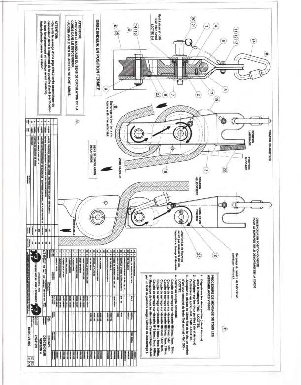
169
170
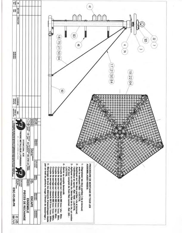
171
IHRG Appendix B Model Specific Rappel/ Cargo Configuration B.1 Bell 205/210/212/214B/412 Rappel/ Cargo Configuration
 B.1 Bell 205/210/212/214B/412 Rappel/ Cargo Configuration B.1.1 Aircraft Rappel Configuration a. Remove right side of (5) persons forward facing seat. b. Right side door post installed c. Approved cargo
Manual winch MANISTOR 100 and 200
 Manual wall winch Manual winch MANISTOR 100 and 200 Instruction manual UK 173-192.10-3 PRODUCT DEVELOPED AND MANUFACTURED ACCORDING TO NF EN 13157 STANDARD REGISTERED DESIGN To ensure the constant improvement
SpanSet Gotcha CRD User Instructions. SpanSet Certified Safety
 SpanSet Gotcha CRD User Instructions SpanSet Certified Safety 1 Table of contents Description 3 Preparation 4 Rescue of casualties 4 Alternatives for recovering the rescuer 5 Storage and transportation
BRAKE WINCH RUP 503-[T/BT] EQUIPMENT FOR LIFTING LOADS. AT 053-[T/BT] xx
![BRAKE WINCH RUP 503-[T/BT] EQUIPMENT FOR LIFTING LOADS. AT 053-[T/BT] xx](/thumbs/88/115945274.jpg "BRAKE WINCH RUP 503-[T/BT] EQUIPMENT FOR LIFTING LOADS. AT 053-[T/BT] xx") Reference number: BRAKE WINCH RUP 503-[T/BT] EQUIPMENT FOR LIFTING LOADS DESIGNATED USE The brake winch RUP 503-[...]T series is a load lifting / lowering device. Device is equipped with safety brake for
Reference number: BRAKE WINCH RUP 503-[T/BT] EQUIPMENT FOR LIFTING LOADS DESIGNATED USE The brake winch RUP 503-[...]T series is a load lifting / lowering device. Device is equipped with safety brake for
Serial Number: Lot Number: Purchase Date: General Factors Accepted / Rejected Supportive Details or Comments. Accepted Rejected.
 Full Body Harness Harness Model: General Factors / Supportive Details or Comments 1.) Hardware: (includes D-rings, buckles, keepers, and back pads) Inspect for damage, distortion, sharp edges, burrs, cracks
PHOENIX, ARIZONA USA
 NEW PRODUCTS MODEL: US-AASS-80 DESCRIPTION: Cantilever Arm 80 MEETS OSHA & ANSI Z359.14 CLASS B 1-800-850-5914 PHOENIX, ARIZONA USA WWW.ULTRASAFEUSA.COM CANTILEVER ARM The Ultra-Safe cantilever arm has
Load Ring bolted > VWBG < in pink
 RUD-Art.-Nr.: 8503693-EN / 03.014 Load Ring bolted > VWBG < in pink EN Safety instructions This safety instruction/declaration has to be kept on file for the whole lifetime of the product. Translation
LITERIDER 2&3 IMPORTANT WARNING. 2Bike (1x) Bolt (1x) Nut (1x) Small Hex Wrench (1x)
 Bolt (1x) Nut (1x) Small Hex Wrench (1x)") LITERIDER 2&3 3 Bike (1x) Bolt (1x) Flat Washer (2x) Nut (1x) Large Hex Wrench (1x) 2Bike (1x) wrench (1x) Small Hex Wrench (1x) keys (2x) Long Strap (1x) 2-Zip Strips (6x) 3-Zip Strips (9x) Wheel strap
LITERIDER 2&3 3 Bike (1x) Bolt (1x) Flat Washer (2x) Nut (1x) Large Hex Wrench (1x) 2Bike (1x) wrench (1x) Small Hex Wrench (1x) keys (2x) Long Strap (1x) 2-Zip Strips (6x) 3-Zip Strips (9x) Wheel strap
Premium PowerPoint Presentation. Rigging Review
 Premium PowerPoint Presentation Rigging Review Chapter 1 Hoisting Safety Review: What about the CG Symmetrical vs. Asymmetrical Balanced and Unbalanced Lifting Lug Hooks Angle Deformation Safety Gates
DBI SALA Confined Space Rescue Davit System
 Instructions for the following series products: Rescue Davit System (See back page for specific model numbers.) User Instruction Manual For Davit Rescue System This manual should be used as part of an
HELMETS SAVE LIVES!!! ALWAYS WEAR A PROPERLY FITTED HELMET WHEN YOU RIDE YOUR SCOOTER. DO NOT RIDE AT NIGHT. AVOID RIDING IN WET CONDITIONS.
 HELMETS SAVE CORRECT FITTING - MAKE SURE YOUR HELMET COVERS YOUR FOREHEAD. LIVES!!! ALWAYS WEAR A PROPERLY FITTED HELMET WHEN YOU RIDE YOUR SCOOTER. DO NOT RIDE AT NIGHT. AVOID RIDING IN WET CONDITIONS.
VL 2K LIFT D-L WINCH INSTRUCTIONS (Applies to P/Ns , , , , , )
") VL 2K LIFT D-L WINCH INSTRUCTIONS (Applies to P/Ns 3714022, 3714028, 3714034, 3714040, 3714043, 3714046) REIMANN & GEORGER CORPORATION MARINE PRODUCTS BUFFALO, NY P/N 6112103 04/09/18 1 SAFETY 1.1 INTRODUCTION
VL 2K LIFT D-L WINCH INSTRUCTIONS (Applies to P/Ns 3714022, 3714028, 3714034, 3714040, 3714043, 3714046) REIMANN & GEORGER CORPORATION MARINE PRODUCTS BUFFALO, NY P/N 6112103 04/09/18 1 SAFETY 1.1 INTRODUCTION
MANUAL SEALLESS STEEL STRAPPING TOOL MODEL A
 OPERATION MANUAL / SPARE PARTS LIST MANUAL SEALLESS STEEL STRAPPING TOOL MODEL A337.0001 13.1912.01 13191201.en/MAS/ 10.02 INDEX PAGE 1 SAFETY INSTRUCTIONS 2 2 WARRANTY CONDITIONS AND LIABILITY 4 3 APPROPRIATE
NEXT EXIT THE GREAT OUTDOORS POPULATION: EVERYONE
 2017 NEXT EXIT THE GREAT OUTDOORS POPULATION: EVERYONE SportRack is proud to offer safe, quality products that allow you to take full advantage of your vehicle s carrying capacity. SportRack accessories
Operator s Manual. All-Terrain Wheelchair
 Operator s Manual All-Terrain Wheelchair By Brandon Calavan Ana Groff Steve Benn Dylan Rinker Sebastian Pineo Team 1 Faculty Advisor: John Enderle Teaching Assistant: Sarah Brittain Client: Melody Kettle
RESCUE LIFTING DEVICE RUP 503-[...] AT 053-[...] xx
![RESCUE LIFTING DEVICE RUP 503-[...] AT 053-[...] xx](/thumbs/90/102827869.jpg "RESCUE LIFTING DEVICE RUP 503-[...] AT 053-[...] xx") EN 1496:2006 / B Reference number: RESCUE LIFTING DEVICE RUP 503-[...] AT 053-[...] xx DESIGNATED USE The rescue lifting device RUP 503-[...] series is a component of rescue system. Using this device the
EN 1496:2006 / B Reference number: RESCUE LIFTING DEVICE RUP 503-[...] AT 053-[...] xx DESIGNATED USE The rescue lifting device RUP 503-[...] series is a component of rescue system. Using this device the
PF30 Inspection & Maintenance Manual
 PF30 Inspection & Maintenance Manual Version 1.4 (September 2011) 1 Contents 1. Warning!!!!!!!!!! 3 2. Terminology! Figure 1: POWERFAN PF30 and Drope!!!! 4! Figure 2: POWERFAN PF30 with belt guard retracted!!
2018 ACCESSORY ATTACHMENTS OWNER S MANUAL
 2018 ACCESSORY ATTACHMENTS OWNER S MANUAL WWW.RADPOWERBIKES.COM We are here to help! Please contact us at SUPPORT@RADPOWERBIKES.COM or 1-800-939-0310 if you have questions. REV031418 Welcome Thanks you
DE8410 FIVB Official Beach Volleyball Net
 DE8410 FIVB Official Beach Volleyball Net User s Manual For Safety Use Caution Misuse causes unexpected injury and net damages. Keep the net away from solid and sharp materials. Keep the rope away from
Hand winch MANIBOX GR
 Hand spurgear winch Hand winch MANIBOX GR Instruction manual UK 34-331.09/9 PRODUCT DEVELOPED AND MANUFACTURED ACCORDING TO STANDARD NF EN 13157 In an endeavour to improve its products, HUCHEZ reserves
On the Go Swing System Instruction Manual
 On the Go Swing System Instruction Manual WARNING READ ENTIRE MANUAL BEFORE USE. THIS SWING IS NOT A TOY. THIS SWING IS ONLY TO BE USED UNDER ADULT SUPERVISION. CONSULT WITH A CHILD S THERAPIST ON HOW
RehabPro Standard Pulley (M30, M50, M70, M30F, M50F, M70F)
") RehabPro Standard Pulley (M30, M50, M70, M30F, M50F, M70F) User Manual RehabPro, Inc. 28215 North 25th Dale Phoenix, AZ 85085 602-317-7207 (phone) E-mail: sales@rehabpropulleys.com E-mail: kris@rehabpropulleys.com
RehabPro Standard Pulley (M30, M50, M70, M30F, M50F, M70F) User Manual RehabPro, Inc. 28215 North 25th Dale Phoenix, AZ 85085 602-317-7207 (phone) E-mail: sales@rehabpropulleys.com E-mail: kris@rehabpropulleys.com
Operator s Manual Series 2400 Material Lift
 October 2013 Operator s Manual Series 2400 Material Lift USA 7514 Alabonson Rd. Houston, TX 77088 ph: 281-999-6900 fax: 281-999-6966 CANADA 75 Saltsman Drive, Unit 5 Cambridge, Ontario N3H 4R7 ph: 519-653-5300
Read Instructions carefully before use. Rollator is designed for indoor & outdoor use. Do NOT use as a wheelchair or as a transport chair.
 Charcoal Red Seat Height 500-10191 500-10195 19 500-10211 500-10215 21 500-10241 500-10245 24 User Manual Read Instructions carefully before use. Rollator is designed for indoor & outdoor use. Do NOT use
THOR 10 HAMMER CAGE INSTRUCTIONS
 75 " 7m 78 4" m 6" 8.8m 45 ".70m 4.9deg 6 4" 6m 44 4".67m 75 " 7m 9 4" 0m 44".m 497 4".64m The 70, Thor Hammer Cage, consists of four heavy duty aluminum net poles. The unique pole structure reduces the
User Instruction Manual For Davit Rescue System
 Instructions for the following series products: Rescue Davit System Model numbers 8004000 and 8302500 User Instruction Manual For Davit Rescue System This manual should be used as part of an employee training
RIDE Inc. Rigscape Drilling Rig Procedures
 2016 RIDE Inc. Rigscape Drilling Rig Procedures Special Instructions/Conditions of Use Reading user procedure manual prior to use is essential Only persons that have been deemed competent in the operation
Operating manual for descender and rescue lifting devicesafescape
 Operating manual for descender and rescue lifting devicesafescape SD 72 As on 28.05.09 Contents 1. General information... 3 2. Technical description... 3 2.1. Technical data... 3 2.2. Assembly... 5 2.3.
SECTION 2 RING MOUNT
 SECTION 2 RING MOUNT Rotax aircraft engines are manufactured and supported by Rotax GmbH of Austria. Read and understand the Rotax manuals completely before starting with the engine installation, as they
Quattrocycle BV. Quattrocycle. User Manual. Last update February Quattrocycle BV Bremkant EJ Middelbeers. User Manual Quattrocycle 1
 Quattrocycle User Manual Last update February 2010 Quattrocycle BV Bremkant 6 5091 EJ Middelbeers User Manual Quattrocycle 1 Table of Contents Page Chapter 1: Introduction 3 Chapter 2: Instructions for
SETTING THE HANDLE HEIGHT ON THE ROLLATOR
 Model No: Maximum User Weight: 10910C (Lightweight) 10928C (Heavy duty) 125kg (20st) (Lightweight) 170kg (27st) (Heavy duty) Height of handles: 780-915mm (30.5-36 ) (Lightweight) 790-930mm (31-36.5 ) (Heavy
Ladies Shopper Bike Assembly Manual 28C03
 Ladies Shopper Bike Assembly Manual 28C03 Ecosmo Ltd 1 Know your bike 1. Wheel 2. Rear Derailleur 3. Chain 4. Crank Set 5. Pedal 6. Seat Quick Lock 7. Saddle and Post 8. Frame 9. Front Light 10. Front
Floor Mount Socket. T: +44 (0) F: +44 (0)
 F: +44 (0)") G-Davit : Floor Mount Socket USER INSTRUCTION MANUAL A davit socket for installation bolted to a high strength flooring material. Suitable for both fall arrest use and lifting. EN795 Class B, PPE Anchor
G-Davit : Floor Mount Socket USER INSTRUCTION MANUAL A davit socket for installation bolted to a high strength flooring material. Suitable for both fall arrest use and lifting. EN795 Class B, PPE Anchor
Instruction Manual: VelectriX Urban 2.0
 Instruction Manual: VelectriX Urban 2.0 CONTENTS Safe Riding Recommendations Page 2 Pre-Ride Checklist Page 3 Display and Controls Page 4 Maintenance Page 8 Warranty Page 9 Contact Details Page 10 Service
PFC Lightweight Composite Push Up Mast. Operating Manual
 PFC Lightweight Composite Push Up Mast Operating Manual South Midlands Communications Ltd SM House, School Close Chandlers Ford Industrial Estate Eastleigh, Hampshire SO53 4BY United Kingdom Tel: +44 (0)23
GUIDELINES FOR USE GUARD
 GUIDELINES FOR USE GUARD G Guard Range of Load Arrestors Retractable Fall Arrest Safety Line for Protection of Machinery & Sensitive Loads GLOBESTOCK MILE OAK INDUST. ESTATE, MAESBURY ROAD, OSWESTRY, SHROPSHIRE
Assembly Instructions & Manual. Configuration subject to change
 Assembly Instructions & Manual Configuration subject to change O R Y X II A S S E M B L Y I N S T R U C T I O N S & M A N U A L IMPORTANT PRECAUTIONS WARNING: To reduce the risk of serious injury, read
FAILURE TO COMPLY WITH THE MANUFACTURER S INSTRUCTIONS CAN LEAD TO SERIOUS INJURY OR DEATH OF THE PASSENGER/RIDER!
 FAILURE TO COMPLY WITH THE MANUFACTURER S INSTRUCTIONS CAN LEAD TO SERIOUS INJURY OR DEATH OF THE PASSGER/RIDER! Installation instructions for the Yepp Mini The Yepp Mini is suitable for carrying children
sealed self retracting lifeline
 Supplemental Instruction to: Sealed Self Retracting Lifeline (See back page for specific model numbers.) Supplemental Instruction User Instruction Manual sealed self retracting lifeline Use this Supplemental
RIDE Inc. Rigscape Service Rig Procedures
 2016 RIDE Inc. Rigscape Service Rig Procedures Special Instructions/Conditions of Use Reading user procedure manual prior to use is essential Only persons that have been deemed competent in the operation
Ground Release Shackle
 Operator Manual Subhead Advantages: In the process of installing Slide Rail, the shackle connecting the top of posts, panels, and sheeting must be removed manually. This is normally done by climbing on
RehabPro Speed Pulley (M100S & M100FS) User Manual
 User Manual") RehabPro Speed Pulley (M100S & M100FS) User Manual 1. Inspection of Delivery Before unpacking the Pulley please inspect the packaging for shipping damage. Observable damage should be noted prior to signing
RehabPro Speed Pulley (M100S & M100FS) User Manual 1. Inspection of Delivery Before unpacking the Pulley please inspect the packaging for shipping damage. Observable damage should be noted prior to signing
On the Go Swing System Instruction Manual
 On the Go Swing System Instruction Manual WARNING READ ENTIRE MANUAL BEFORE USE. THIS SWING IS NOT A TOY. THIS SWING IS ONLY TO BE USED BY TRAINED PERSONNEL, SUCH AS AN OCCUPATIONAL THERAPIST, PHYSICAL
Trampoline & Enclosure Assembly Instructions
 Trampoline & Enclosure Assembly Instructions Safe user weight 250 lbs (115 kg) Version 718602 The information in this document is subject to change without notice. Copyright Springfree Trampoline Inc.
OPERATING INSTRUCTIONS (Translation) Rope Winch Type , , ,75
 Rope Winch Type , , ,75") OPERATING INSTRUCTIONS (Translation) Rope Winch Type 4202.0,5 4585.0,5 4585.0,75 GB The length of the rope is correct if: 1. User groups Duties Operator Operation, visual inspection Specialist Assembly,
OPERATING INSTRUCTIONS (Translation) Rope Winch Type 4202.0,5 4585.0,5 4585.0,75 GB The length of the rope is correct if: 1. User groups Duties Operator Operation, visual inspection Specialist Assembly,
Rhino-Rack 570, 580. Important Information
 Important: Please read these instructions carefully prior to installation. Please refer to your fitting instruction to ensure that the kayak carrier is installed in the correct locations. Check the contents
GOTCHA CRD. Rescue, hoisting and abseiling equipment EN341 / EN1496 CE0158 TECHNICAL DATA
 Rescue, hoisting and abseiling equipment Height Safety Lifting Load Control Safety Management GOTCHA Rescue Range GOTCHA CRD Rescue, hoisting and abseiling equipment EN341 / EN1496 CE0158 TECHNICAL DATA
Duo/Trio Office Bike Owner s Manual
 Duo/Trio Office Bike Owner s Manual Welcome Congratulations on choosing to enhance your productivity and wellness with LifeSpan. You ve made a healthy decision, as the need for increased amounts of daily
NEXT EXIT THE GREAT OUTDOORS
 NEXT EXIT THE GREAT OUTDOORS POPULATION: EVERYONE SportRack is proud to offer safe, quality products that allow you to take full advantage of your vehicle s carrying capacity. SportRack accessories perfectly
8MAY15 US RACK, Inc Falcon Drive, Madera, CA
 8MAY15 US RACK, Inc. - 2850 Falcon Drive, Madera, CA 93637-559-661-3050 INSTRUCTIONS for Bedrail-mounted MOTORCYCLE RACK, Model 2001-4TRA WARNING: Do NOT attempt to install or use this rack without following
GUIDELINES FOR USE -GUARD
 GUIDELINES FOR USE -GUARD G-Guard Range of Load Arresters Retractable able Fall Arrest Safety Line for Protection on of Machinery & Sensitive Loads Directive 2006/42/EC GLOBESTOCK Ltd MILE OAK INDUST.
Operator s Manual. Series 2100 Contractor Lifts
 October 2013 Operator s Manual Series 2100 Contractor Lifts! Before operating this lift, read and understand this Operator s Manual. Become familiar with the potential hazards of this unit. Call SUMNER
Assembly Guide ST200 FUNCTIONAL TRAINER
 Assembly Guide ST200 FUNCTIONAL TRAINER Assembly Guide ST200 FUNCTIONAL TRAINER To avoid possible damage to this Functional Trainer, please follow these assembly steps in the correct order. Before proceeding,
SAMPLE PAGE. Section 2... Wire Rope
 Section 2...................................................... Wire Rope Never use any kind of clip to directly connect two straight lengths of wire rope to form a continuous piece. Do not make up slings
Santa Fe Cycles Assembly Guide Introduction
 Santa Fe Cycles Assembly Guide Introduction Congratulations on your purchase of your new Santa Fe bicycle. You have purchased a bicycle that has many features and qualities. Please take a few minutes and
Tern Rapid Transit Rack
 Tern Rapid Transit Rack Rapid Transit Rack Specifications Cargo load capacity: 25kg (55.1 lb) Compatibility Fits most Tern Link, Verge and Vektron models. Trolley Handle not compatible with certain models.
Installation, operation & maintenance manual - original version
 Installation, operation & maintenance manual - original version AVK gate valves for water and wastewater Series 01, 02, 06, 12, 15, 18, 20, 26, 32, 33, 36, 38, 50, 55 and 636 COPYRIGHT AVK GROUP A/S 2018
Instruction Manual: VelectriX Foldaway
 Instruction Manual: VelectriX Foldaway CONTENTS Safe Riding Recommendations Page 2 Pre-Ride Checklist Page 3 Display and Controls Page 4 Quick Guide to Folding Page 6 Battery Instructions Page 7 Maintenance
Height Safety Lifting Load Control Safety Management GOTCHA Rescue Range TECHNICAL DATA
 GOTCHA CRD Rescue, hoisting and abseiling equipment Height Safety Lifting Load Control Safety Management GOTCHA Rescue Range EN341 / EN1496 CE0158 TECHNICAL DATA Supplier : SpanSet Type : Gotcha CRD Device
SUPPLEMENT TO AIRCRAFT FLIGHT MANUAL FOR MOTOR-DRIVEN ROPE WINCH TYPE RPM 11/01
 SUPPLEMENT TO AIRCRAFT FLIGHT MANUAL FOR MOTOR-DRIVEN ROPE WINCH TYPE RPM 11/01 (Langenthaler-Winch) Aircraft-Manufacturer: Avions Robin SA Type of Aircraft: Robin DR 300-180R DR400-180R DR 400-200R DR
INSTRUCTION GUIDE S-WORKS ROAD CARBON CRANKSET (Carbon and Alloy OSBB cups)
") INSTRUCTION GUIDE S-WORKS ROAD CARBON CRANKSET (Carbon and Alloy OSBB cups) THIS BRIEF INSTRUCTION GUIDE CONTAINS IMPORTANT INFORMATION. PLEASE READ CAREFULLY AND STORE IN A SAFE PLACE. Congratulations!
INSTRUCTION GUIDE S-WORKS ROAD CARBON CRANKSET (Carbon and Alloy OSBB cups) THIS BRIEF INSTRUCTION GUIDE CONTAINS IMPORTANT INFORMATION. PLEASE READ CAREFULLY AND STORE IN A SAFE PLACE. Congratulations!
OPERATING INSTRUCTIONS (Translation) Rope winch Type KWE 250 KWV 300 KWE 650 KWV 650 KWE 1000 KWV 1250
 Rope winch Type KWE 250 KWV 300 KWE 650 KWV 650 KWE 1000 KWV 1250") 1. User groups Duties Operator Operation, visual inspection Specialist personnel Assembly, disassembly, repair, maintenance Tests OPERATING INSTRUCTIONS (Translation) Rope winch Type KWE 250 KWV 300 KWE
1. User groups Duties Operator Operation, visual inspection Specialist personnel Assembly, disassembly, repair, maintenance Tests OPERATING INSTRUCTIONS (Translation) Rope winch Type KWE 250 KWV 300 KWE
VERSA BIKE RACK INSTRUCTIONS
 VERSA BIKE RACK INSTRUCTIONS Models #8, 8 Important This rack is designed for use with a or. receiver hitch. The rack is designed to hold a maximum of two bicycles. Do not use it for anything other than
ROLLGLISS TOP/R350. Safety and rescue system. Operating and Maintenance Instructions
 ROLLGLISS TOP/R350 Safety and rescue system Operating and Maintenance Instructions Table of Contents 1 1. Safety Instructions...2 1.1 Important instructions for use of the safety and rescue systems 1.2
M S I C R A N E S C A L E
 2 M E A S U R E M E N T S Y S T E M S I N T E R N A T I O N A L Table of Contents Forward...3 Safe Operating Guidelines...4 Operating Suggestions...4 Handling Hoist Motion...4 Safe Loading and Rigging
Hand winch MANIBOX VS
 Hand wormgear winch Hand winch MANIBOX VS Instruction manual UK -.09/ PRODUCT DEVELOPED AND MANUFACTURED ACCORDING TO STANDARD NF EN INSTRUCTION MANUAL FOR COMMISSIONING AND MAINTENANCE In an endeavour
Assembly, Installation and operating. instructions for. Söll-Xenon anchorage device
 Assembly, Installation and operating instructions for Söll-Xenon anchorage device according to EN 795:1996 Part No: XE-... (The following must be completed by the operator in permanent waterproof ink.)
Wellhead Mast. Installation and Operation Guide. Nanometrics Inc. Kanata, Ontario Canada
 Installation and Operation Guide Nanometrics Inc. Kanata, Ontario Canada 2001 2005 Nanometrics Inc. All Rights Reserved. Installation and Operation Guide The information in this document has been carefully
CORPORATE SAFETY MANUAL
 CORPORATE SAFETY MANUAL Procedure No. 32-0 Revision: Date: May 2005 Total Pages: 10 PURPOSE To provide general guidelines for the inspection of all ropes, chains, cables, slings, etc. used for personnel
Operator s Manual. 2010, 2015, 2020, 2025 Material Lifts
 July 2017 Operator s Manual 2010, 2015, 2020, 2025 Material Lifts! Before operating this lift, read and understand this Operator s Manual. Become familiar with the potential hazards of this unit. Call
Apollo Standard Port, Full Port & One Piece Flanged Ball Valves Installation, Operation, & Maintenance Manual
 I854000.D Apollo Standard Port, Full Port & One Piece Flanged Ball Valves Installation, Operation, & Maintenance Manual Introduction This manual presents guidelines for the Installation, Operation and
Versie Date: USAGE AND SAFETY MANUAL SPREADERBEAMS
 USAGE AND SAFETY MANUAL SPREADERBEAMS 1. INTRODUCTION: The spreader system exists of modular traverses with possibility of different spans. Each spreaderbeam exists of two head section complete with shackles
Z5160 Load adapter Mounting instructions (1.2 EN)
") Z560 Load adapter Mounting instructions (. EN) WARNING! CAUTION! IMPORTANT! Note: References in the manual This refers to a potentially dangerous situation which may lead to personal injury. This refers
Z560 Load adapter Mounting instructions (. EN) WARNING! CAUTION! IMPORTANT! Note: References in the manual This refers to a potentially dangerous situation which may lead to personal injury. This refers
Overspeed governors (113 OG Моment 250 MR, 114 OG Moment 250 A3, 115 OG Moment 250 MRL, 119 OG Moment 250 MRL/1)
") Overspeed governors (113 OG Моment 250 MR, 114 OG Moment 250 A3, 115 OG Moment 250 MRL, 119 OG Moment 250 MRL/1) Instructions for installation and operation 113 OG Моment 250 MR 115 OG Moment 250 MRL Overspeed
Overspeed governors (113 OG Моment 250 MR, 114 OG Moment 250 A3, 115 OG Moment 250 MRL, 119 OG Moment 250 MRL/1) Instructions for installation and operation 113 OG Моment 250 MR 115 OG Moment 250 MRL Overspeed
Chapter 2 Rigging. Cutting Wire Rope. Anchoring Wire Rope to Drum. Winding Wire Rope Onto Drum
 Chapter 2 Rigging Cutting Wire Rope The wire rope must be tightly seized on both sides of the point where the wire rope will be cut, as shown in Figure 2-1. Seize the wire rope with either seizing wire
All rights reserved 2010 Les Fabrications TJD inc.
 Les Fabrications TJD inc. All rights reserved Les Fabrications TJD inc., Rivière-du-Loup, G5R 5X9. No copy or reproduction of this manual shall be made, in whole or in part, without the prior wrote permission
USER GUIDE ROLLING WALKERS INSTRUCTIONS FOR USE JANUARY, Maximum User Weight: 170kg (Do not exceed this weight)
") USER GUIDE ROLLING WALKERS INSTRUCTIONS FOR USE JANUARY, 2013 Model Nos: BE07889T Maximum User Weight: 170kg (Do not exceed this weight) Model Nos: BE07890TB Maximum User Weight: 227kg (Do not exceed this
USER GUIDE ROLLING WALKERS INSTRUCTIONS FOR USE JANUARY, 2013 Model Nos: BE07889T Maximum User Weight: 170kg (Do not exceed this weight) Model Nos: BE07890TB Maximum User Weight: 227kg (Do not exceed this
TECHNICAL INFORMATION
 TECHNICAL INFORMATION Models No. TD0101, TD0101F Description Impact Driver L PRODUCT P 1/ 14 CONCEPT AND MAIN APPLICATIONS Models TD0101 and TD0101F are cost-competitive 100N.m-class impact driver developed
Repair instructions. Pivot bushing replacement. XL-AS10001RM-en-DE Rev B
 Repair instructions Pivot bushing replacement XL-AS10001RM-en-DE Rev B Table of contents Table of contents 1 General information... 3 1.1 Safety information...3 1.2 Legal information...4 1.3 Order and
SG-7R46 SG-7R45 BR-IM41-R CJ-7S40 WARNING CAUTION SERVICE INSTRUCTIONS. Inter-7 Hub. Inter-M Brake Cassette joint NOTE:
 t WARNING It is important to completely understand the operation of your bicycle's brake system. Improper use of your bicycle's brake system may result in a loss of control or an accident, which could
MAGNETIC INDOOR CYCLING BIKE
 MAGNETIC INDOOR CYCLING BIKE SF-B1805 USER MANUAL IMPORTANT! Please retain owner s manual for maintenance and adjustment instructions. Your satisfaction is very important to us, PLEASE DO NOT RETURN UNTIL
Instruction Manual: VelectriX Urban 2.0+
 Instruction Manual: VelectriX Urban 2.0+ CONTENTS Safe Riding Recommendations Page 2 Pre-Ride Checklist Page 3 Display and Controls Page 4 Maintenance Page 8 Warranty Page 9 Contact Details Page 10 Service
OPERATOR S MANUAL. The Will-Burt Company 169 S. Main Street Orrville, OH 44667
 OPERATOR S MANUAL The Will-Burt Company 169 S. Main Street Orrville, OH 44667 www.willburt.com TP-5439301-A, 2017 The Will-Burt Company Original Instructions Warranty Will-Burt warrants its QEAM HDTM
Trilogy Theory of Operation
 INSTALLATION & OVERVIEW... 2 Load Height... 2 Approach Angle... 2 Footprint... 3 Protrusion... 3 Mounting the... 4 General Torque Specs... 4 OPERATION OF BIKE RACK... 5 Loading Bikes... 5 Unloading Bikes...
BC Shackle. Made in the China. Alloy Steel Anchor Shackle. Instructions for handling and use - Please read in full before using this device
 BC Shackle Made in the China Alloy Steel Anchor Shackle Instructions for handling and use - Please read in full before using this device Index 1.) Introduction 2.) Warnings / General Use Guidelines 3.)
Rear Drive System SERVICE INSTRUCTION. Specifications SI-R670B
 - SERVICE INSTRUCTION SI-R670B t Rear Drive System Before use, read these instructions carefully, and follow them for correct use. In order to realize the best performance, we recommend that the following
INSTRUCTIONS FOR USE
 INSTRUCTIONS FOR USE 88004X Series D-Ring Extender 5000 lb Rated Connector Complies with ANSI Z359.1-1998, ANSI 10.14 and OSHA 1926 regulations and requirements. Reliance Industries P.O. Box 2046 Deer
OPERATIONS MANUAL IMPORTANT SAFETY INFORMATION
 OPERATIONS MANUAL IMPORTANT SAFETY INFORMATION Please read, understand and follow all safety information contained in these instructions prior to the use of this tool. Retain these instructions for further
SERIES 2 RAMP OWNER S MANUAL TOOLS REQUIRED: BEFORE YOU BEGIN... Read and understand these instructions before beginning a ramp setup.
 SERIES 2 RAMP OWNER S MANUAL BEFORE YOU BEGIN... Read and understand these instructions before beginning a ramp setup. Use caution and care for your back when lifting, pushing, pulling, folding or unfolding
STRONGMAN. High Security U-Lock 100% HARD. ENGLISH 2-x DEUTSCH x-x ESPANOL x-x ITALIANO x-x JAPANESE x-x FRENCH x-x. LOCKS BY KNOG
 STRONGMAN High Security U-Lock 100% HARD LOCKS BY KNOG www.knog.com.au ENGLISH 2-x DEUTSCH x-x ESPANOL x-x ITALIANO x-x JAPANESE x-x FRENCH x-x ENGLISH CONTENTS Strongman components 4 How to lock your
USER MANUAL Do not throw away these instructions. Read and understand these instructions prior to use of the Lad Grab Safety System.
 PRODUCT NAME: LAD GRAB Patent Pending PART NUMBERS: *LAD GRAB2TOPBRACKET, *LAD GRAB2CABLEGUIDE, *LAD GRAB2BOTTOMBRACKET, & CABLE3/8AIRCRAFT USER MANUAL Do not throw away these instructions. Read and understand
CHAPTER 5 REWIND STARTERS
 GENERAL INFORMATION CHAPTER 5 REWIND S Rewind starters used on vertical shaft Tecumseh engines are top mount horizontal pull style or side mount vertical pull style. Horizontal shaft engines use side mounted
Maintenance manual. Flight helmet LA100 PP
 Flight helmet LA100 PP010298-00 Table of Contents Page Table of Contents 1/21 - Warning notice 2/21 - Helmet description 3/21 - Introduction 4/21 1 Chinstrap 5/21 2 Inner liner elements 6/21 3 Edge roll
7130 Lancer Rear Drive Magnetic Commercial Indoor Cycling Bike
 7130 Lancer Rear Drive Magnetic Commercial Indoor Cycling Bike Owner s Manual Made in Taiwan INDEX IMPORTANT SAFETY INFORMATION... 1 EXPLODED DRAWING... 2 PARTS LIST... 3 ASSEMBLY INSTRUCTION... 4-9 USER
Congratulations! You own an R9 Cobra! A compact, fast handling and powerful crossbow for your serious shooting enjoyment!
 COBRA SYSTEM R9 COBRA SYSTEM R9 CROSSBOW INSTRUCTION MANUAL Congratulations! You own an R9 Cobra! A compact, fast handling and powerful crossbow for your serious shooting enjoyment! The limb set comes
RATCHET RELEASE SHACKLE
 RATCHET RELEASE SHACKLE INNOVATIVE PILING EQUIPMENT HYDRAULIC PILING HAMMERS EURO RATCHET RELEASE SHACKLE FOR STEEL ERECTION OPERATORS INSTRUCTIONS & SPARE PARTS LIST EXCAVATOR MOUNTED VIBRATORS EXCAVATOR
INSTRUCTION GUIDE S-WORKS ROAD CARBON CRANKSET (Carbon and Alloy OSBB cups)
") INSTRUCTION GUIDE S-WORKS ROAD CARBON CRANKSET (Carbon and Alloy OSBB cups) THIS BRIEF INSTRUCTION GUIDE CONTAINS IMPORTANT INFORMATION. PLEASE READ CAREFULLY AND STORE IN A SAFE PLACE. Congratulations!
INSTRUCTION GUIDE S-WORKS ROAD CARBON CRANKSET (Carbon and Alloy OSBB cups) THIS BRIEF INSTRUCTION GUIDE CONTAINS IMPORTANT INFORMATION. PLEASE READ CAREFULLY AND STORE IN A SAFE PLACE. Congratulations!
G -saverll USER INSTRUCTION MANUAL GLOBESTOCK. Retractable Fall Arrest Lifeline & Retrieval System. EN 360 EN 1496: C lass B
 USER INSTRUCTION MANUAL G -saverll Retractable Fall Arrest Lifeline & Retrieval System EN 360 EN 1496: C lass B GLOBESTOCK MILE OAK INDUSTRIAL ESTATE, MAESBURY ROAD, OSWESTRY, SHROPSHIRE SY IO 8GA TEL:
SAFE WORK PROCEDURE. Location of Equipment Written By: Approved By: Date Created Last Revision
 Page 1 of 5 Location of Equipment Written By: Approved By: Date Created Last Revision School: Facilities & Operations Brent Vandenbosch Gordon Howe October 14, 2009 new Room: n/a Barry Hamilton HAZARDS
BELT DRIVE INDOOR CYCLING BIKE SF-B1712 USER MANUAL
 BELT DRIVE INDOOR CYCLING BIKE SF-B1712 USER MANUAL IMPORTANT! Please retain owner s manual for maintenance and adjustment instructions. Your satisfaction is very important to us, PLEASE DO NOT RETURN