OMGA5KN Iss Copyright Geotechnical Instruments (UK) Ltd
|
|
|
- Deborah Gregory
- 6 years ago
- Views:
Transcription

1
2 Page 2 of 126 TABLE OF CONTENTS Manual guidelines... 6 Hazard warnings and safety symbols... 6 Notes... 6 Introduction... 7 Safety instructions... 7 MCERTS CIRIA EU Declaration of conformity The GA5000 gas analyser The GA GA5000 standard product GA5000 optional products and accessories Temperature probe (optional) Anemometer (optional) H2S filter (optional) Gas analyser manager GAM (optional) GPS (optional) Bluetooth Internal Flow (optional) Instrument accessory products GA5000 instrument features Physical characteristics of the instrument panel Analyser features and keys General operational instructions Switching the instrument on Power on self-test Switching the analyser off Instrument status icons... 23
3 Page 3 of 126 Instrument LED power states Changing between parameters Entering data Instrument main gas read screen Storage Battery/charging Power supply front and back drawing: Cleaning instructions Memory Warning and error codes Remote updates Menu key Operation settings Timers Gas Check View data Set alarms Adjust flow fail Technician login Device settings Date and time Bluetooth Device information Diagnostics Navigation (optional) User settings Operating language Units of measurement ID selection Routes... 46
4 Page 4 of 126 Adjust backlight Adjust volume User Prompts Exit menu Taking readings Creating an ID Answering site questions Answering ID questions Special action Configuration of the data logging option The gas flow measurement screen How to use the Internal Flow (Optional) How to use an anemometer (optional) How to use an H2S filter (optional) How to use a temperature probe (optional) How to identify a borehole using the GPS feature (optional) Taking gas and flow measurement Calibration Calibration introduction Frequency of calibration best practice Calibration gases Calibration set-up Calibration equipment Gas analyser Calibration processes best practice Gas check in fresh air Calibration mixtures 1, 2 & Restore to factory Calibration history Calibration summary... 74
5 Page 5 of 126 Problem solving Warning and error display Service Warranty policy Important notice to all customers Appendices safety instructions Instructions for safe use Italian language MCERTS Instructions for safe use German language MCERTS Instructions for safe use French language MCERTS Instructions for safe use Spanish language MCERTS Instructions for safe use Portuguese langauge Instructions for safe use - Chinese language Instructions for safe use - Polish language Instructions for safe use - Romanian language Glossary of terms
6 Page 6 of 126 MANUAL GUIDELINES Hazard warnings and safety symbols Information in this manual that may affect the safety of users and others is preceded by this warning symbol. Caution - Failure to follow the correct information may result in physical injury which in some cases could be fatal. If the equipment is used in a manner not specified by the manufacturer, the protection provided by the equipment may be impaired. General product label symbols are listed as follows: CE conformity-the CE-marking is the manufacturer's statement to the EU authorities that the product complies with all relevant CE-marking directives. VDE mark is a symbol for electrical, mechanical, thermal, toxic, radiological and other hazards. If the CSA mark appears with the indicator "US" or "NRTL" it means that the product is certified for the U.S. market, to the applicable U.S. standards. Separate collection, handling and disposal for waste electrical and electronic equipment and its components. II 2G Electric shock warning. Double insulated construction - does not require an Earth. Equipment group and category. G = gases; the type of explosive atmosphere. Fuse Refer to operators manual. Specific marking of explosion protection (ATEX only). IECEx licenced mark (IECEx only). Equipment for indoor use only. Notes Important/useful information and instructions are shown clearly throughout the manual in a note format. For example: Note: For further information please contact Technical Support at Geotech on +44(0) or technical@geotech.co.uk.
7 Page 7 of 126 INTRODUCTION This manual explains how to use the GA5000 landfill gas analyser. The GA5000 is designed to meet all current demands for landfill & Brownfield site monitoring protocols set by government legislation in Europe and the United Kingdom. Utilised with dedicated software, the GA5000 becomes an extremely powerful detection, monitoring and change indicator tool. The 5000 series of gas analysers complies with Part 15 of the FCC Rules. Operation is subject to the following two conditions: 1. This device may not cause harmful interference. 2. This device must accept any interference received, including interference that may cause undesired operation. Safety instructions The 5000 series of gas analysers can be used for measuring gases from landfill sites and other sources as described in this manual. The operator may be exposed to harmful gases during the use of the instrument. Inhaling these gases may be harmful to health and in some cases may be fatal. It is the responsibility of the user to ensure that he/she is adequately trained in the safety aspects of the gases being used and appropriate procedures are followed. In particular, where hazardous gases are being used the gas exhausted from the analyser must be piped to an area where it is safe to discharge the gas. Hazardous gas can also be expelled from the instrument when purging with clean air. The instrument has been designed to be used in explosive atmospheres as defined by the classification. The instrument can be configured to measure low levels of several gases, but may not be certified for use in potentially explosive atmospheres of these gases. It is the responsibility of the operator to determine the protection concept and classification of equipment required for a particular application and whether these gases create a potentially explosive atmosphere. Note: Gas analysers are a sensitive piece of scientific equipment, and should be treated as such. If the equipment is used in a manner not specified by the manufacturer, the protection provided by the instrument may be impaired. For ATEX and IECEx the 5000 series of gas analysers are certified to Hazardous Area Classification II 2G Ex ib IIA T1 Gb (Ta = -10ºC to +50ºC) It is vital instructions are followed closely. It is the responsibility of the operator to determine the protection concept and classification required for a particular application.
8 Page 8 of 126 (Reference European ATEX directive 2014/34/EU) The following instructions apply to equipment covered by certificate numbers SIRA 11ATEX2197X and IECEx SIR X: The equipment may be used with flammable gases and vapours with apparatus group IIA and temperature class T1. The equipment can contain gas sensing heads for the detection of particular gases. The inclusion of a sensor does not infer that the equipment is suitable for the use of gases with a temperature class of less than T1. The equipment is only certified for use in ambient temperatures in the range -10ºC to +50ºC and should not be used outside this range. The equipment must not be used in an atmosphere of greater than 21% oxygen. Repair of this equipment shall be carried out in accordance with the applicable code of practice. When used in a hazardous area only use GF5.2 temperature probe (SIRA 11ATEX2197X and IECEx SIR X). For connector C, the GF5.4 anemometer (BVS 04ATEXE194) for use with ATEX only. The analyser should not be connected to any other devices in the hazardous area including the GF-USB lead (connector A) or GF3.9 battery charger (connector B) supplied with the analyser. Do not charge, recharge or open in a potentially explosive atmosphere. In hazardous area only use Temperature Probe GF5.2 in Connector B. Connector C (Uo=10V,lo=5mA,Po=50mW,Ci=0,Li=0,Co=100uF,Lo=1000mH), Connector B (Uo=5V,lo=6mA,Po=7mW,Ci=0,Li=0,Co=100uF,Lo=1000mH) MAXIMUM NON-HAZARDOUS SUPPLIES: Connector A - Um=6V Connector B - Um=10.1V The safe area apparatus that is to be connected to the USB Port shall be a Safety Extra Low Voltage (SELV) or Protective Extra Low Voltage (PELV) circuit. Only a Geotechnical Instrument battery pack part number or is permitted as a replacement. This battery pack shall only be changed in a safe area by Geotech personnel or authorised distributors. Only Battery Charger type GF3.9 shall be used to recharge the batteries via Connector B. If the equipment is likely to come into contact with aggressive substances, e.g. acidic liquids or gases that may attack metals, or solvents that may affect polymeric materials, then it is the responsibility of the user to take suitable precautions, e.g. regular checks as part of routine inspections or establishing from the material s data sheet that it is resistant to specific chemicals that prevent it from being adversely affected,
9 Page 9 of 126 thus ensuring that the type of protection is not compromised. The relative pressure range is +/-500 mbar. Note, however, that the input pressure should not exceed +/- 500 mbar relative to atmospheric pressure and the output pressure should not exceed +/- 100 mbar relative to atmospheric pressure. For CSA (Canada) the 5000 series of gas analysers are certified to Hazardous Area Classification CLASS PROCESS CONTROL EQUIPMENT - Intrinsically Safe and Non-Incendive Systems - For Hazardous Locations Ex ib IIA: Model GA5000, GEM5000 and BIOGAS 5000 Methane Detectors; portable, battery powered with non-fieldreplaceable Battery Pack P/N or ; intrinsically safe and providing intrinsically safe circuits ( [ib] for Zone 1) to Model GF5.2 Temperature Probe (Connector B) and with entity output parameters as tabulated below; Temperature Code T1; -10 ºC Tamb. +50ºC. Connector Entity Parameters Uo (V) Io (ma) Po (mw) Co (uf) Lo (mh) Ci (uf) Li (mh) B C Note: This device has been investigated for electrical safety features only.
10 Page 10 of 126 For CSA (USA) the 5000 series of gas analysers are certified to Hazardous Area Classification CLASS PROCESS CONTROL EQUIPMENT - Intrinsically Safe and Non-Incendive Systems For Hazardous Locations - CERTIFIED TO U.S. STANDARDS AEx ib IIA: Model GA5000, GEM5000 and BIOGAS 5000 Methane Detectors; portable, battery powered with non-fieldreplaceable Battery Pack P/N or ; intrinsically safe and providing intrinsically safe circuits ( [ib] for Zone 1) to Model GF5.2 Temperature Probe (Connector B) and with entity output parameters as tabulated below; Temperature Code T1; -10 ºC Tamb. +50ºC. Connector Entity Parameters Uo (V) Io (ma) Po (mw) Co (uf) Lo (mh) Ci (uf) Li (mh) B C Note: This device has been investigated for electrical safety features only. MCERTS MCERTS is the UK Environment Agency's Monitoring Certification Scheme. The scheme provides a framework within which environmental measurements can be made in accordance with the Agency's quality requirements. The scheme covers a range of monitoring, sampling and inspection activities. Note: MCERTS - Cross sensitivity tests using hydrogen sulphide were not carried out on this instrument, therefore, users should be aware if H 2S is present on sites, as there may be an interferential effect. MCERTS promotes public confidence in monitoring data and provides industry with a proven framework for choosing monitoring systems and services that meet the Environment Agency's performance requirements. The Environment Agency has established its Monitoring Certification Scheme (MCERTS) to deliver quality environmental measurements. The MCERTS product certification scheme provides for the certification of products according to Environment Agency performance standards, based on relevant CEN, ISO and national standards. MCERTS certified instruments have been tested by an independent body to ensure that they meet certain performance requirements. In addition, the manufacturer of an MCERTS product is regularly audited to ensure that the performance requirements of the certification are being continually met. The 5000 series of gas analysers have been certified to Version 3.1 of the Performance Standards for Portable Emission Monitoring Systems.
11 Page 11 of 126 CIRIA The CIRIA guideline Assessing the risks posed by hazardous ground gases to buildings proposes that gas concentrations and flow rates should be monitored. As an example methodology, they suggest using a gas analyser to first measure flow and pressure and then afterwards to measure gas concentration. The logging profile option offers frequency of data to be collected within a timed period which, in return, identifies a gas profile of the sample point being monitored, information about whether the sample point is performing correctly, when the peaks occur and whether air is drawn in after a certain period. This logging option is available on firmware software version Versions of the GA5000 analyser range with internal flow on firmware version and above have the ability to take measurements according to the CIRIA guidelines, while still allowing other users to take the measurements as before.
12 Page 12 of 126 EU Declaration of conformity
13 Page 13 of 126

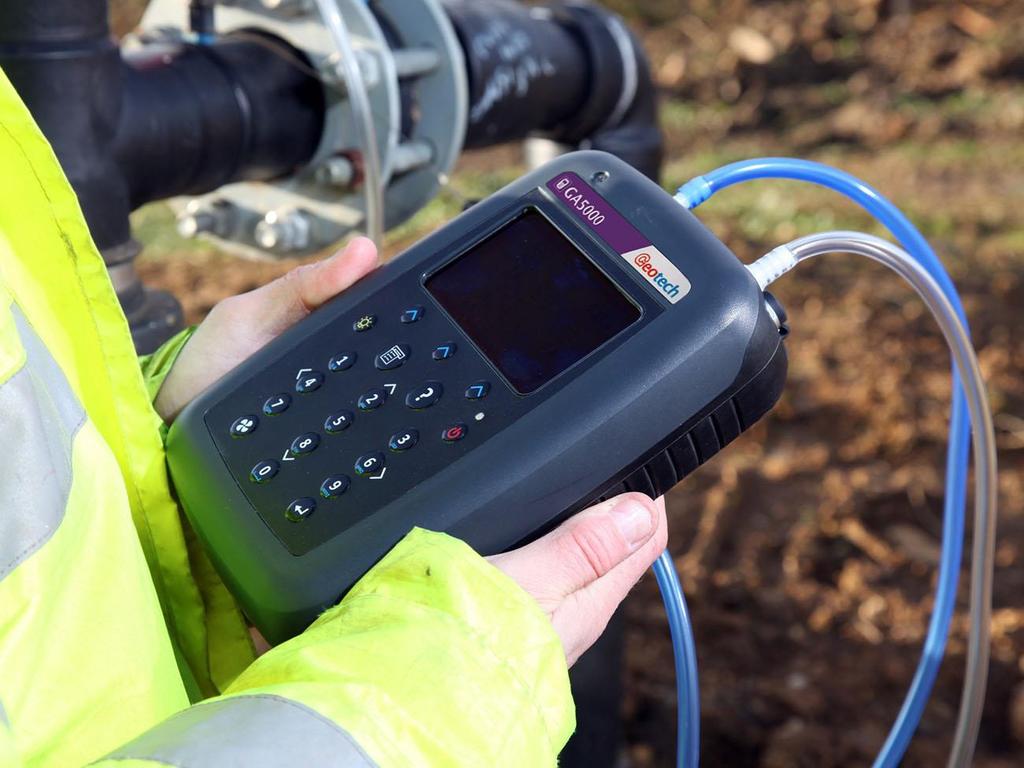
14 Page 14 of 126 THE GA5000 GAS ANALYSER The GA5000 GA5000 gas analyser The GA5000 gas analyser is designed to monitor landfill gas extraction systems and is designed to meet all current demands for landfill & Brownfield site monitoring protocols set by government legislation in Europe and the United Kingdom. Benefits: Easy to use and calibrate. Supports environmental legislation compliance. Market leading reliability. Standardises monitoring routines. Easy transfer of data. Features: ATEX, IECEx certified, CSA and UKAS calibration (ISO17025) MCERTS certified. Measures % CH4, CO2 and O2. Up to 6 gases can be measured. Peak and previous readings shown. Simultaneous display of all gases. 3 year warranty.
 B In-line water trap tubing & filter E Safety")
15 Page 15 of 126 Event log. Data logging. Applications: Landfill gas monitoring. Waste to energy. Site investigation. GA5000 standard product A B E C D F Refrence A Hard carry case D H2S filter (optional if the compensated CO cell is fitted) B In-line water trap tubing & filter E Safety manual C Gas analyser instrument F Charger with adapters
16 Page 16 of 126 GA5000 OPTIONAL PRODUCTS AND ACCESSORIES The GA5000 gas analyser has a number of optional products for purchase which enhance the usability and enable further analysis of data and reading information. Note: For more information on the features listed in this section please contact Sales at Geotech on +44(0) or Sales@geotech.co.uk. Temperature probe (optional) The GA5000 gas analyser has the facility to automatically display and record the borehole temperature via an optional temperature probe. When a temperature probe is fitted the temperature reading will be displayed on the Main Gas Read Screen and recorded with all other data. Note: Temperature probes with an Ex label are part of the GA5000 Ex certification SIRA 11ATEX2197X and IECEx SIR X, and therefore certified for use under the same conditions as the analyser. Anemometer (optional) The GA5000 gas analyser has the facility to automatically display and record high flow via an optional anemometer probe. It is designed to plug into the instrument and instantly provide a flow indication. An anemometer probe adds flow measurements to the professional reporting ability of the GA5000 range along with gas concentrations, pressure and temperature. The anemometer has a simple connection, a narrow diameter measurement head (11mm), a wide temperature operating range (up to 80oC) and indicates flows up to 40 m/sec. When an anemometer probe is fitted to the analyser the flow will be displayed in the Main Gas Read Screen and recorded with all other data. Flow can be measured in either m/s (gas velocity) or m3/hr (volume flow rate). In order to calculate the volume flow rate the pipe diameter will need to be entered into the instrument, either manually or via the Gas Analyser Manager software. Note: The anemometer probe is ATEX certified for use in a potentially explosive atmosphere under Ex certificate BVS 04ATEXE194. H2S filter (optional) The GA5000 gas analyser has the capability to use an H2S filter and is required as standard if the compensated CO cell is fitted and configured at the time the instrument is manufactured. H2S gas can have a cross-gas effect on the CO reading. By using a filter, the H2S is removed from the gas sample, therefore providing a more accurate CO reading. The filter only needs to be used when you are trying to get rid of any possible cross gas effects H2S might have on other gases. Do not use the filter on all boreholes.
17 Page 17 of 126 Gas analyser manager GAM (optional) Gas Analyser Manager (GAM) enables the operator to maximise the operation of the gas analyser. It enables direct communication with the unit, features a simple upload and download facility and is fully compatible with the latest Microsoft operating systems. Features: Organisation and transfer of borehole IDs and readings to and from the gas analyser. Configuration of the gas analyser. Flexible grouping of the IDs. Structured organisation of transferred data. Automatic detection of instrument type and available options. Secure data mode to prevent tampering. First time set-up wizard. Enable flow measurements for GA5000 gas analysers. GPS (optional) An optional GPS feature is available for the GA5000 gas analyser. It enables the site engineer to automatically locate borehole IDs using GPS satellite signal from predefined borehole IDs uploaded from Gas Analyser Manager or set on the analyser when out in the field prior to taking a reading. The GPS reading data is stored for each measurement reading providing an audit trail confirming that a reading was taken. Bluetooth The analysers are fitted with a Bluetooth receiver which enables the operator to download readings and upload IDs without the need to connect the analyser to a PC via a USB lead. Internal Flow (optional) The GA5000 gas analyser has the capability to measure the gas flow from a borehole without the need for an additional flow pod. The user is automatically prompted to take this measurement during the normal reading sequence. This function can be selected as On or Off for each ID using Gas Analyser Manager. If it is off the user will not be prompted to measure the flow.


 GF5.")
 GA6.4 GA6.5 GF5.")
18 Page 18 of 126 Instrument accessory products Optional accessory and replacement parts must ONLY be purchased for the GA5000 gas analyser direct from Geotech or your agent. Please contact for further details on pricing and how to order. Description Order Code Hard carry case GF2.5 Soft carry case GF5.1 Battery charger and adaptors GF3.9 Anemometer (ATEX certified) GF5.4 H2S/Hydrocarbon filters Temperature probe (ATEX certified) GA6.4 GA6.5 GF5.2 Check gas regulator and tubing for calibration gas. Calibration gas canister. GA6.8 Please contact for gas canister concentrations In-line water trap filter & tubing GF1.8
 Water trap with barbed filters (pack")
 Gas ports connectors (pack of 10) MC10")
 GA2.3 Spare window for the soft carry case GF5.")
19 Page 19 of 126 Water trap with barbed filters (pack of 10) Water trap with barbed filters (pack of 30) GA4.9 GA4.9(30) Gas ports connectors (pack of 10) MC10 Sampling tube 5m length flexible PVC tubing (3/16 id) GA2.3 Spare window for the soft carry case GF5.3 Gas Analyser Manager (GAM) GAM USB lead GFUSB


20 Page 20 of 126 GA5000 INSTRUMENT FEATURES Physical characteristics of the instrument panel FRONT REAR N A E B C D F G TOP H I J K L M A On / Off key J Charger/temperature port B Backlight key K Flow inlet C Menu key L Gas inlet D Assistance key M USB port E Soft-keys N Rear label F Enter key G Pump key H Accessory port I Gas outlet
21 Page 21 of 126 Analyser features and keys Ref Feature Function Front A On / Off key Turns the instrument on and off B Backlight key Enables the operator to turn the backlight on/off on the analyser display panel. C Menu key Press the Menu key to view and maintain User, Device and Operation settings. D Assistance key Pressing this brings up helpful on screen prompts. E Soft-keys The function of the three soft-keys on the front of the instrument panel is determined by menu options taken. Functions vary from screen to screen F Enter key Press this key to confirm anything you have inputted using the keypad. G Pump key Press the Pump key to start or stop the pump. Top H Accessory port Connection used to connect the anemometer to the analyser. I Gas outlet Where the gas gets expelled when taking a sample. It is always our recommendation that you have the yellow tube connected to ths port, and that you trail the outlet of the tube away from you so that the gas is vented safely. J Charger/temperature port Connection used to connect the analysers charger and temperature probe. Please note, only one can be used at one time. K Flow inlet This is where you connect up the differential port of your Pitot or orifice plate to ascertain a flow reading (if required). L Gas inlet Connect the white sample tube here and the other end of the tube to your sample point connection. M USB port Connection used to connect the analyser to a PC via USB cable (optional) Rear N Rear label Contains all of the instrument s information
22 Page 22 of 126 GENERAL OPERATIONAL INSTRUCTIONS Switching the instrument on 1) To switch on the analyser, press and hold the On/Off key. The Geotech logo will display followed by the instrument warm up. 2) Following the instrument warm up, the Date and Time screen is displayed prompting the technician to set the date and time and required format. 3) When complete select the soft-key to Exit and the Power On Self-test screen is displayed followed by instrument status. Instrument status displays the instruments service due date, serial number, options, service scheme and software version. Text will also display stating Self-test complete. 4) Select the soft-key Next to move onto the next screen and the Technician Login screen is displayed. 5) Use the cursor keys to move through the list of ID s. Select either the required Technician ID from the list followed by the soft-key Accept, or select Default followed by the soft-key Accept to continue to the Main Gas Read Screen. Note: The selected technician ID is displayed at the top left corner of the Main Gas Read Screen. Power on self-test When switched on, the read-out will perform a pre-determined self-test sequence. During this time many of the analyser s functions are tested, including: General operation Gas flow measurement Calibration Battery charge level During the self-test the following information is also displayed: Manufacturer s service due date The last gas check date Software version programmed Date format Serial number Operating language The currently enabled sales option Note: The self-test should only be done with the analyser sampling fresh air.
23 Page 23 of 126 Switching the analyser off 1) To switch off the analyser, press and hold the On/Off key, at which point a clean air purge will be carried out and the instrument will then switch off. 2) If for any reason the analyser locks up and will not switch off in this manner, press and hold the On/Off key for 15 seconds; this will force the instrument to switch off. Instrument status icons The following icons may be displayed on the instrument screen: Icon Description Icon Description Battery charge state Gives the operator an estimation of the battery charge state. For example 100% gives about 8 hours use in the field and 50% would mean that there is approximately 4 hours battery life remaining. Pump status This icon is displayed along with a counter showing the pump run-time. This counts down where the operator has specified the pump run-time; if not it counts up; the icon turns red when stalled. GPS signal strength This icon shows the signal strength the analyser s GPS module is able to provide. Full, okay and fair strength respectively. This indicates when Bluetooth has been enabled. The colour changes from grey to blue when connected. Data logging This icon indicates that the data logging feature is in operation. Battery charge state Indicates less than 2 hour of charge remaining. Pump stalled This icon is displayed when the pump stalls. The instrument s gas inlet (or outlet) may be blocked. This warning is most commonly caused by a waterlogged or dirty sample filter. Change the sample filter and check for obvious blockages in the sample tubes. Alternatively, a small amount of adjustment can be made to the low flow detection point to compensate for minor changes in the performance of the pump fitted to the instrument. GPS failure The GPS was unable to get a line of sight lock on enough satellites. Or, it may be that it hasn t had time to get a lock. Language This icon indicates the currently selected operating language. This can be changed via the main menu. Service overdue This icon indicates that the analyser is overdue for its service.
24 Page 24 of 126 Legacy mode This icon indicates that the analyser is in legacy mode and hence is ready to connect to a PC. USB disabled This icon indicates that the analyser has reached a battery critical state, and hence has turned off its USB connectivity. Instrument LED power states When the instrument is powered on a LED power light is visible on the front of the analyser, located above the On/Off key. The following LED power light states are as follows: Steady yellow Flashing (rapid) Flashing (slow) Flashing yellow Flashing red Unit turning on. This will extinguish when software has loaded correctly. Unit is powering off. Power off is being delayed for purge/shutdown handling. Unit is turning off due to power button being pressed. Unit is turning off due to critically low battery. Note: Pressing and holding the power button for ~20s resets the analyser. Changing between parameters By default, the instrument displays the Main Gas Read Screen (for gas measurement). The instrument will return to this screen after power on or when returning from the menus. The Scroll keys can be used to switch to another measurement screen. Entering data During normal operation the operator may be prompted to enter data or information via the keypad, i.e. entering an ID code or setting an alarm level. When entering data into the instrument all fields are fixed format and are populated from the left. Text: Entering text uses similar multi-tap functionality as a mobile phone. Key the numeric/alpha key pad the required number of times to select the appropriate letter. To key numeric data continue to press the numeric/alpha key until the required number is displayed. Numeric data: To enter a new date 09/11/11 the operator would type in using the numeric keypad in the following sequence:- * 0_/ / * 09/ / * 09/1_/ * 09/11/ * 09/11/1_ * 09/11/11 Press the Enter key to confirm/accept data keyed.

25 Page 25 of 126 Any mistakes can be corrected using the soft-key Delete which will delete the last digit typed. Alternatively, the sequence can be retyped before the Enter key is pressed and the existing numbers will be pushed off the screen. Note: The instrument will not allow invalid data to be entered; this should be deleted and re-entered. Instrument main gas read screen The Main Gas Read Screen is considered to be the normal operating screen and all operations are carried out from this starting point. The actual data shown on this display will depend on the version of the instrument and the options that have been selected. In general, all of the main readings will be shown. Time and date stamp Borehole ID Green figure = live reading Baro Battery indicator Blue figure = fixed reading Soft key options Self test has passed Main Gas Read Screen Storage The analyser should not be exposed to extreme temperature. For example, do not keep the analyser in a hot car. When not in use analysers should be kept in a clean, dry and warm environment, such as an office and protect the analyser with either the soft carry case or store in the hard carry case provided with the instrument. The instrument should be discharged and fully charged at least once every four weeks, regardless of indicated charge state. Battery/charging The battery used in the 5000 series of gas analysers is nickel metal hydride and manufactured as a pack from six individual cells. This type of battery is not so susceptible to the top-up charging memory effects as nickel cadmium batteries, although it is not recommended that the unit is given small top-up charges. Note: To reach optimum charge, it is recommended that the instrument is switched off when being charged and remains switched off during the charging process.

26 Page 26 of 126 A full charge will take approximately 4 hours from a fully discharged battery. The battery charger is NOT covered by the Ex certification. The battery must be charged only in a safe area. The battery charger is intelligent and will indicate when the unit is charging and charged. The instrument must be charged ONLY using the battery charger supplied with the instrument. The battery charger supplied is intended for indoor use only. Please ensure adequate ventilation whilst charging. Typically, a fully charged battery will last 7-8 hours. A quick 30 minute charge can be used to give approximately one hours use in the field but this may shorten the battery life. Temperature can dramatically affect the battery life; please take this into account when estimating battery life. Note: Connect the charger to the mains attaching the appropriate adaptor. Power supply front and back drawing: Charger input: Input voltage: V AC ± 10% Input frequency: Input current: Charger output Ouput voltage: Output current: 50-60Hz ± 10% 240VAC 10.1VDC max 1.5A max Note: This charger has been internally restricted to 1.5A.
27 Page 27 of 126 Cleaning instructions Do NOT use any cleaning agents to clean the analyser or battery charger as they may have an adverse effect on the safe use of these devices. Memory The analyser's memory is stored in a readings and configuration database. The analyser will prompt when its memory is full, and you will not be able to store any further readings. Please download your readings via GAM or the Basic Download Software and then clear the memory. Note: The analyser should never be stored for prolonged periods with valuable data in its memory. It is advisable to download all readings to GAM at the end of each day s monitoring. To clear the memory, please refer to the Gas Analyser Manager (GAM) operating manual. Warning and error codes When switched on the instrument will perform a predetermined self-test sequence taking approximately ten seconds. During this time many of the instrument s working parameters and settings are checked. If any operational parameters are out of specification or if the pre-programmed recommended calibration/service date has passed, errors or warnings may be displayed. Note: For further information please refer to section 10.0 Problem Solving. Remote updates The 5000 range of analysers (GA5000, GEM5000 and BIOGAS 5000) can be updated to the latest version of operating software using the free Geotech 5000 updater software. This allows customers to update their analyser s operating software at their convenience rather than waiting to return the analyser for service. The Geotech 5000 updater software needs to be installed on to a PC by a user with administrator rights, it is then ready to be used by the end-user. A GFUSB download cable is required along with a PC with access to a reasonably fast internet connection. This allows the users to check and download the latest data files from the web. What you need Administrator rights (or access to IT person) Access to the internet and address Geotech s GFUSB download lead Registration Go to Enter the registration information including the analyser s serial number (on the rear label) Wait for an with your access information and link to the file Select the embedded link which takes you to a new web page
28 Page 28 of 126 Enter the login details ( address and password) provided in the you received from us when you registered (not your own address) Select the 5000 series updater software.zip file from available downloads. Select Save as and store it locally on your desktop or similar (this may take some time dependant on internet connection speed) Installation of the 5000 updater software This requires administrator rights. Unzip the file (extract contents), note its location (do NOT run from the compressed folder) To do this, right click the zip folder and select extract all Save the new unzipped folder to a location on your computer Open this folder and double click the setup.exe (administration rights will be required) Follow the on-screen instructions, accepting where necessary. (Please note the progress bar doesn t move for about a minute) Installation of XP Drivers This requires administrator rights. Locate the folder that contains the downloaded files (noted from before) Unzip the folder XPRNDIS_drivers.zip Turn the analyser on and wait for it to warm up Press the menu key Select device settings Select 3 for device information Change the comms mode to GA5K by pressing the comms mode soft key Connect the analyser to the PC via the USB Lead Windows will start the Found New Hardware Wizard Select No, not at this time click next Select Install from a list or specific location (advanced) and then click next Unselect search removable media (floppy, CD-ROM ) Select Include this location in the search: Browse to the location of the XPRNDIS_divers which were previously unzipped and click next
29 Page 29 of 126 Select continue or accept if any notifications appear. The drivers will now be installed Installation of Vista and Win 7 drivers This requires administrator rights. Turn the analyser on and wait for it to warm up Press the menu key Select device settings Select 3 for device information Change the comms mode to GA5K by pressing comms mode soft key Connect the analyser to the PC via the USB Lead Follow the onscreen instructions and accept all of the prompts The drivers will now be installed Updating the analyser Once all of the above operations are completed the software is fully installed and the instrument is ready to be updated. This can be done by a user who does not have administration rights on their PC. Ensure the analyser is fully charged - you do NOT want the analyser turning off during the update process Turn the analyser on and wait for it to start-up Navigate to the main read screen and press the menu key. Select device settings. Press 3 for device information Change the comms mode to GA5K by pressing Comms mode soft key (Please note: if you have just installed the drivers the analyser may be in GA5K mode already) Connect the analyser to the PC via the Geotech GFUSB lead. Start the Geotech 5K updater software Press the Check internet button The software will now attempt the download the data files to the PC This may take several minutes depending on your internet speed Due to individual company s firewalls and I.T. policies the update cannot always be done via this option. You will receive an error message at this point if unsuccessful. Refer to section for an alternative method.
30 Page 30 of 126 It may also take a minute at this point for the analyser to be detected as connected, please wait for the software to show the analyser as connected Once connected the software will be ready to update, press update which will copy the files to the analyser memory The analyser will then start to update, and may restart several times. Please wait for the analyser to show back on the update software as connected. Do not turn off or disconnect the USB lead until this point The analyser is now fully updated. Please note that you may need to adjust the backlight on the analyser: (menu key > user settings > 4 Adjust Backlight > press 6 to make it lighter until you can see the screen. Remember to hit save ). Now set your analyser back to legacy mode. (menu key > device settings > 3 Device information > press Comms mode soft key.) Your analyser will not work with GAMS unless it is in legacy mode Update from file If the update from Check Internet option does not work you can try the following steps. Each company may have certain IT policies in place that stop the download of certain files which may stop the successful download of the update file. You may need help from you I.T. department to download this. Click here to download the update file ( When prompted select the save as function, and save the file to a location you can access later. Do not select open This may take several minutes depending on your internet speed Follow the instructions as per section Updating the analyser However, chose Select file instead of Check internet Navigate to where you saved the file (G5000_UPDATE_FILE.5kc) Click open to select the file The rest of the process is the same as Updating the analyser
31 Page 31 of 126 MENU KEY The Menu key enables the operator to select options to set up specific parameters and perform operational tasks prior to sample readings being taken or to view data and information stored in the instrument. 1) Select the Menu key on the front of the analyser and the following screen is displayed: Operation settings 2) Press the relevant numeric key on the analyser keypad to select the required option. 3) To exit this menu, select the soft-key Exit on the front of the analyser and the operator is returned to Main Gas Read Screen. OPERATION SETTINGS To access the Operation settings menu, select the Menu key on the front of the analyser. The following menu is displayed: Operation settings menu
 Select Key 1 Timers and the following screen is displayed: Timers 1) Select Key 1 to edit the purge time.")
32 Page 32 of 126 Timers The timers function enables the operator to set standard purge times and set auto-power off if the unit is untouched for the period of time specified. 1) Select Key 1 Timers and the following screen is displayed: Timers 1) Select Key 1 to edit the purge time. Enter the Pump Running Time in seconds; this is the length of time you wish to run the pump to draw the sample, e.g. key in 030 then press the Enter key to accept. 2) Select Key 2 to edit the auto power off time. Enter the Auto power off in minutes; the instrument will automatically power off to preserve the battery life after the specified time if no activity has occurred on the instrument. Press the Enter key to accept. 3) Select the soft-key Exit key to exit the screen and return to the Operation settings menu. Note: Setting the purge time and auto power off functions to zero, disables the option. It is not recommended to reduce the purge time to below 30 seconds. Gas Check This option displays the Gas Check menu and enables the operator to zero and span the gas channels on the instrument. Historical/previous gas checks data can also be viewed and factory settings can be restored. 1) Select the Menu button on the front of the analyser to display the Device Settings menu. Press the soft key to display Operation Settings.
 Select soft-key Exit to exit operation settings and return to the main screen. View data This option enables the operator to view the readings collected and stored on the instrument.")
33 Page 33 of 126 2) Select Key 2 Gas Check and the following menu is displayed: Gas check 3) For more information about the Gas Check Menu please refer to section 9.0 Calibration. 4) Select soft-key Exit to exit operation settings and return to the main screen. View data This option enables the operator to view the readings collected and stored on the instrument. Readings many be downloaded to the optional Gas Analyser Manager (GAM) software if further analysis is required. 1) Select the Menu button on the front of the analyser to display the Device Settings menu. Press the soft-key to display Operation Settings. 2) Select Key 3 View Data and the following screen is displayed: View data 3) Toggle through the reading by selecting Key 4 Scroll left and Key 6 Scroll right on the analyser. Select Key 2 Page up and Key 8 Page down to page through the auxiliary channels listed.
 Select the soft-key Delete followed by the appropriate soft-key to delete a single reading or all filtered readings. Press soft-key Cancel to cancel the deletion request.")
34 Page 34 of 126 4) Select the soft-key Filter to filter the data by sample point ID, or specify before or after date. Press the soft-key Exit to exit the filter menu and return to the View Data screen. Filter data 5) Select the soft-key Delete followed by the appropriate soft-key to delete a single reading or all filtered readings. Press soft-key Cancel to cancel the deletion request. 6) Select the soft-key Exit to exit the view data screen. Set alarms This option enables the operator to define the conditions for which an alarm/target will be triggered. These conditions apply to the general operation of the instrument and are not ID specific. A summary of the alarm settings can be found in Key 3 Summary. Types of alarms Common Alarms Are non-id specific alarms which apply to all the readings taken with the analyser. ID specific alarms Are ID specific, i.e. they will only trigger when a certain Id is being used. Tuning/targets You can also set targets for your gas channels, these will highlight gas channels green as oppose to when they alarm (yellow). These can be common or ID specific.
 Select Key 4 Set Alarms and the following menu is displayed: Set primary alarms 3) Select the corresponding key to select the gas for which you wish to set an alarm/target trigger for, followed by")
35 Page 35 of 126 Setting up alarms/targets 1) Select the Menu button on the front of the analyser to display the Device Settings menu. Press the soft key to display Operation Settings. 2) Select Key 4 Set Alarms and the following menu is displayed: Set primary alarms 3) Select the corresponding key to select the gas for which you wish to set an alarm/target trigger for, followed by Key 1 to change the trigger condition of an alarm. 4) To manually adjust the alarm/target set press (<) Key 4 Scroll left or Key 6 Scroll right (>) and enter the trigger value. Once you are happy, press the middle soft key for save. 5) For pressure, temperature and flow alarms, press the left soft key for Secondary and then select the corresponding key to select the channel for which you wish to set an alarm trigger for, followed by Key 1 to change the trigger condition of an alarm/target. Once you are happy, press the middle soft key for save. Set secoundary alarms 6) To disable all alarm settings, select key 0 Disable All Note: ID specific alarms cannot be added/edited on the analyser, to add/edit ID specific alarms, please use the optional Gas Analyser Manager (GAM) Software.
 Select the Menu button on the front of the analyser to display the Device Settings menu. Press the soft-key to display Operation Settings.")
 less sensitive and Key 6 Scroll right (>) more sensitive. 4) Select the soft-key Save to store the setting or select soft-key Exit to exit the screen without saving the change.")

36 Page 36 of 126 Adjust flow fail This option enables the operator to adjust the flow fail tolerance of the instrument, i.e. the operator can adjust the sensitivity for when the pump will stop operating on the presence of a blockage or low flow. 1) Select the Menu button on the front of the analyser to display the Device Settings menu. Press the soft-key to display Operation Settings. 2) Select Key 5 Adjust Flow Fail and the following screen is displayed: Adjust flow fail 3) Manual adjustment of the flow fail is available via this option and can be carried out with use of Key 4 Scroll left (<) less sensitive and Key 6 Scroll right (>) more sensitive. 4) Select the soft-key Save to store the setting or select soft-key Exit to exit the screen without saving the change. 5) The operator will return to the Operation settings menu. Note: The default setting displays the bar in the centre. BEFORE altering this setting, please contact Technical Support at Geotech on +44(0) or technical@geotech.co.uk Technician login This option enables the operator to select or change a pre-defined technician login and all subsequent readings will be tagged with this Technician Login ID. The technician ID must already have been created using the Gas Analyser Manager (GAM) software and uploaded to the instrument. 1) Select the Menu button on the front of the analyser to display the Device Settings menu. Press the soft key to display User Settings.
 The operator will return to the User settings menu.")
37 Page 37 of 126 3) Select Key 6 Technician login and the following screen is displayed: Technician login 4) Use the cursor keys to move throughout the list of IDs displayed; select the Enter key to select choice of ID, default if no IDs are listed or soft-key Skip to skip the selection. 5) The operator will return to the User settings menu. Note: If no technicians are loaded via GAM this section is skipped during start up and the Technician ID icon is removed from the menu.
 Select the Menu key on the front of the analyser to display the Device Settings menu followed by Key 1 Date and Time and the following screen is displayed: Date and time 2) Select Key 1 Set Date")
38 Page 38 of 126 DEVICE SETTINGS Date and time This option enables the operator to set the instrument date and time or to receive and update the settings automatically from satellite signal. 1) Select the Menu key on the front of the analyser to display the Device Settings menu followed by Key 1 Date and Time and the following screen is displayed: Date and time 2) Select Key 1 Set Date and key in the required date. Type the date using the numeric keypad. Press the soft-key Date Format to toggle and select the required date format i.e. dd/mm/yy. Press the Enter key to confirm and update the date setting. 3) Select Key 2 Set Time and key in the required time (hh:mm). Type the time using the numeric keypad and press the Enter key to confirm the update. 4) The operator may also change the default time zone. Selecting the Key 4 Scroll-left or Key 6 Scroll right to move through the different time zones. Press the Enter key to confirm your default setting. 5) Select Key 3 to toggle between Manual Update and Automatic Update in order to choose how the date and time is set if updating from satellite signal. Manual Used to manually obtain and update the date and time from the satellite signal when requested. Select soft-key Set now to set date and time from satellite when available. Automatic Used to automatically update the date and time received from the satellite signal when available. This option is only available when the GPS option is fitted to the analyser at the time of manufacture. 6) Select the soft-key Exit to exit and return to the Device Settings menu.

 Select Key 2 Bluetooth and the following screen is displayed: Bluetooth options 3) Enter the Pairing PIN value when prompted by your computer for the device s pairing code.")
39 Page 39 of 126 Bluetooth This option enables the operator to set and utilise Bluetooth technology. This may be useful when downloading gas readings from the analyser to the PC instead of connecting the analyser to a PC via a USB lead. Bluetooth may also be used to transfer Site IDs to other 5000 series gas analysers if required. 1) Select the Menu key on the front of the analyser to display the Device Settings menu. 2) Select Key 2 Bluetooth and the following screen is displayed: Bluetooth options 3) Enter the Pairing PIN value when prompted by your computer for the device s pairing code. 4) Select soft-key Exit to exit the screen and return to the Device Settings menu. Device information This option displays default instrument information and settings such as serial number, service due date, last zero calibration date and last span calibration date. 1) Select the Menu key on the front of the analyser to display the Device Settings menu. 2) Select Key 3 Device Information and the following screen is displayed: Device information

40 Page 40 of 126 3) The information displayed on this screen is informational only and cannot be edited by the operator. The operator may be asked serial number, service due date and version number information when contacting Geotech. Note: The communications setting Legacy mode is for use with GAM version 1.5 and above. GA5K mode is for use with the 5000 series updater tool. 4) Select soft-key Exit to exit the screen and return to the Device Settings menu. Diagnostics This option enables the Geotech Technical Support Team to identify and resolve issues with the instrument and settings. If required, the operator may be asked to confirm the diagnostics displayed. 1) Select the Menu key on the front of the analyser to display the Device Settings menu. 2) Select Key 4 Diagnostics and the following screen is displayed: Diagnostics 3) Select soft-key Next to display the next screen, Previous to return to the previous screen, or select soft-key Exit to exit this screen and return to the Device Settings menu. Note: For further information please contact Technical Support at Geotech on +44(0) or technical@geotech.co.uk.
41 Page 41 of 126 Navigation (optional) This option enables the operator to switch the GPS Navigation functionality on or off. (This is optional and dependent upon purchasing the navigation option). 1) Select the Menu key and the Device Settings menu is displayed. 2) Select Key 5 Navigation On to switch on the GPS navigation functionality or Key 5 Navigation Off to switch the GPS navigation functionality off. Note: For further information please refer to section 8.0 Taking Readings.

42 Page 42 of 126 USER SETTINGS To access the User settings menu, select the Menu key on the front of the analyser to display the Operating Settings menu followed by the soft-key to display User Settings menu. The following menu is displayed: User settings menu To exit the user settings menu select the soft-key Exit. Operating language This option enables the operator to specify the operating language displayed for the instrument. 1) Select Key 1 Operating Language and the following screen is displayed: Set language Set the required language for the gas analyser by selecting the appropriate function key. Choose from, on the first page: Key 1 Key 2 English Spanish

 Select Key 2 Units of Measurement and the following screen is displayed: Units of measurement menu 2) To set the required units of measurement toggle and choose from the")
43 Page 43 of 126 Key 3 Key 4 Key 5 Key 6 French German Italian Portuguese Use the soft-keys to move to the next page for further language options, including simplified Chinese 2) To exit this option, select the soft-key Exit and the operator is returned to the User Settings menu. Units of measurement This option enables the operator to specify the default units of measurement for the instrument. 1) Select Key 2 Units of Measurement and the following screen is displayed: Units of measurement menu 2) To set the required units of measurement toggle and choose from the following: Key 1 Temperature C F Key 2 Flow scfm m3/hr Key 3 Measurement Inches Millimetres Key 4 Pressure mb H2O Key 5 Balance Balance Residual N2


44 Page 44 of 126 3) Select soft-key Exit to exit this screen and return to the User Settings menu. ID selection The ID selection screen allows the operator to scroll through all IDs, including those uploaded from GAM and added directly onto the instrument, and then make a selection. Detailed information regarding the currently selected ID, such as flow device type and pump runtime, are displayed below:- By selecting Key 5 the operator can toggle between showing 30 IDs and showing 5 IDs with more detailed information relating to the chosen ID. The technician can scroll between the IDs using the following keys on the instrument keypad: Two (2) and eight (8) move the selection up/down Four (4) and six (6) move the selection left/right on the list view One (1) and three (3) move the selection left/right a page in the list view only Seven (7) and nine (9) move the selection to first/last ID Five (5) toggles between the 'ID with information' and 'ID list' Return/enter key selects the desired ID and proceeds to the navigation or reading screen.

45 Page 45 of 126 If there are no IDs present the technician can either add a new ID or press the enter key on the instrument keypad to return to the previous screen. Soft keys: Left - Select 'No ID' and go to the purge/reading screen. Centre - Enabled when there is a list of IDs, allowing the technician to dynamically filter the IDs displayed in the list. Right - Allows the technician to add a new ID to the instrument 'in the field'. Note: If your analyser has firmware version v1.12 or greater, used IDs will have a strikethrough. Changing the sort order By default the IDs are sorted in the order in which they were transferred to the instrument. To change the sort order between unsorted, sort by name or sorted by distance to travel press Key 0. Sorted by original order (not sorted) Sorted alphabetically Sorted by distance to travel Note: The distance Only available when GPS is enabled. For analysers with firmware v1.12 and above: 1) Press the menu key 2) Press the middle soft key for User Settings 3) Press key 3 ID options a. Key 1 to change the sort order b. Key 2 to change how the IDs are displayed c. Key 3 to clear the line through on the current ID being used d. Key 4 to remove the line through on all IDs

.")
46 Page 46 of 126 Routes Using the optional Gas Analyser Manager Software (GAM) you can upload a route, this is a predefine list of IDs that you can go through in an order. This feature is useful if you have a certain order to complete your IDS in. Furthermore if your GA5000 has v1.12 or higher firmware it will strike through your IDs once you have used them. Note: If the analyser is set to route mode (v1.12 and above), the filter box will no longer be there, as you cannot filter in this mode. It will be replaced by Route and the route name. Adjust backlight This option enables the operator to adjust the backlight (brightness). Having this set to a darker setting will help preserve the battery power 1) Select Key 4 Adjust Backlight and the following screen is displayed: Adjust backlight 2) Keys 4 and 6 can be used to adjust the brightness of the display screen. Manual disables the backlight timeout.

47 Page 47 of 126 3) Select the soft-key Save to store the setting or select soft-key Exit to exit the screen without saving the change. 4) The operator will return to the User settings menu. Selecting Key 1 allows the operator to configure the dimmer settings from Auto Dim to Auto Off in order to help preserve power consumption when data logging. This icon represents Auto Dim this enables the backlight idle timeout, which means the backlight will go dim after a specified period of inactivity. This will help save battery life. This icon represents Auto Off this switches the backlight off, saving power. Note: The manually set contrast setting is retained when the read-out is switched off and may require resetting when next switched on. Adjust volume This option enables the operator to adjust the volume for the internal speaker, for example the alarm tone. A lower setting will help preserve the battery power. 1) Select the Menu button on the front of the analyser to display the Device Settings menu. Press the soft-key to display User Settings. 2) Select Key 5 Adjust Volume and the following screen is displayed: Adjust volume
48 Page 48 of 126 3) Manual adjustment of the volume is available via this option and can be carried out with use of Key 4 - Scroll left ( ) volume down and Key 6 - Scroll right (>) volume up. 4) Select the soft-key Save to store the setting or select soft-key Exit to exit the screen without saving the change. 5) The operator will return to the User settings menu. User Prompts This option enables the operator to either turn on or off the context-sensitive user prompts which are displayed during the gas sample process. The analyser will have the user prompts on when it is first used, so if they are no required they can be switched off by selecting soft-key 6 and this will now be its default setting. Prompts can be switched back on at any time by returning to this menu and selecting soft-key 6. Exit menu 1) Press the Menu button on the front of the analyser to exit settings.
49 Page 49 of 126 TAKING READINGS Preliminary checks before taking readings (best practice) Start Prior to use, it is good practice to ensure that: Step 1 ID codes and information uploaded Step 2 Analyser has correct time and date set Step 3 Step 1 Step 2 Step 3 If using GAM ID codes and information have been uploaded from GAM to the analyser. Please see section for more information on this. The instrument has the correct time and date set. The water trap filter is fitted and is clean and dry. Water trap filter is clean and dry Step 4 Step 4 The battery has a good charge (minimum 25% charge, even if only a few readings are required). Battery has good charge Step 5 Gases zeroed Step 5 Step 6 All gas channels have been zeroed, without gas concentration present. If necessary check the span calibration with a known concentration calibration gas. Step 6 Step 7 Take readings. Check span calibration Step 7 Take readings
50 Page 50 of 126 Inhaling hydrogen sulphide gas (H2S) or other harmful gases can cause death. It is the responsibility of the user to ensure that he/she is adequately trained in the safety aspects of using H2S and other harmful gases. In particular, where hazardous gases are being used the gas exhausted from the analyser must be piped to an area where it is safe to discharge the gas. Hazardous gas can also be expelled from the instrument when purging with clean air. Good practice Travel to site with the gas analyser in the vehicle's interior - not in the boot, where it may be subjected to extremes of temperature and possible shock damage. Do not place the gas analyser against anything hot (e.g. gas extraction pipe, car body or in an unattended car during the summer) as this will cause a temperature increase in the gas analyser and may cause erroneous readings. When moving around a site, protect the gas analyser from strong direct sunlight and heavy rain. Always use the water trap! If the water trap becomes flooded, change the filter and ensure all tubes are clear of moisture before re-use. Note: If the exhaust of a 5000 series gas analyser is connected to a pressurised system then this results in a flow of gas out of the inlet flow port. Creating an ID There are two different methods to creating an ID, either via Gas Analyser Manager or via the instrument. If created on the analyer, you can only fill out basic information, such as ID code, description and ID type. Whereas on GAM, you can assign site and ID questions (please see below), assign flow devices, input GPS coordiantes etc. To create an ID on GAM please consult the GAM operating manual. To create an ID on the instrument: 1) Press the left soft-key for Next ID 2) Press the right soft-key for Add 3) Input an ID code using the keypad 4) Press enter 5) Using the corresponding number to input different properties of the ID 6) Once you are happy, press the middle soft-key for add Answering site questions Prior to taking the readings at a particular site, the site questions should be populated, this is only necessary when using site questions, if not, please proceed with the reading as normal. This is accessed via the Special Action menu. The answers to these questions are then stored and appended to each reading stored thereafter, until the site questions are updated for another site. You will need Gas Analyser Manager (GAM) software to create site questions and if you are using Gas Analyser Manager (GAM), this data will be uploaded to GAM along with the reading data. Answering ID questions
 software required), you will be prompted to answer these questions at the end of the reading, this means that")
 From the Main Gas Read Screen select the soft-key Special Action and the following menu is displayed: Special action menu Note: The list of special action options displayed on the special action")
51 Page 51 of 126 Prior to, or after, you have taken the reading, the ID questions should be populated, this is only necessary when using ID questions, if not, please proceed with the reading as normal. When you have uploaded IDs with ID questions assigned to them (Gas Analyser Manager (GAM) software required), you will be prompted to answer these questions at the end of the reading, this means that the answer only equates to that reading. Special action This menu enables the operator to perform the additional following functions out of sequence if so desired. 1) From the Main Gas Read Screen select the soft-key Special Action and the following menu is displayed: Special action menu Note: The list of special action options displayed on the special action menu is dependent upon device type and sequence.
52 Page 52 of 126 The following special actions may be performed: Action Key 1 Simple Gas Function This action enables the operator to take a quick gas reading. The pump will start running automatically when this key is selected. The operator can stop the pump by pressing the pump key on the keypad at any time and the reading can then be stored by selecting soft-key Store. Key 2 Site Questions This action enables the operator to update site questions prior to taking a reading. Key 3 ID Questions This action enables the operator to update ID questions specific to sample points prior to taking a reading. Key 4 Flow This action enables the operator to measure internal flow first when taking a reading. Connect the blue hose to the sample point. The yellow hose can be vented a safe distance from the sample point or re-circulated back into the system. Select either soft-key Zero Flow, Flow Options or Start to commence internal flow. Select softkey Store to store and record the reading. Key 5 Enter Temperature This action enables the operator to manually enter a temperature reading if not using a temperature probe prior to taking a gas measurement. Key 6 Start Logging This action enables the operator to leave the analyser unattended to take samples at a predetermined time. The reading interval and pump run times may be edited prior to commencing the logging cycle.
53 Page 53 of 126 Configuration of the data logging option The analyser can also be set-up to data log 1) Connect the gas inlet (white port) to the sample point. The yellow exhaust hose can be vented a safe distance from the sample point; do NOT re-circulate back into the system. 2) By selecting Next ID the operator can select the ID which is being sampled at present. 3) Once the ID has been chosen the analyser will commence & complete its clean air purge cycle. 4) To gain access to the data logging option the operator will be required to select the Special Action key to obtain the special user options. The data logging option can then be selected via Key 6 to configure the logging parameters. 5) Once the operator has confirmed the logging parameters, select soft-key Start Logging. 6) Once the logging function has been activated the analyser will carry out a 30 second warm-up (displayed below the temperature read out at the right of the main gas read screen) and begin the first sample. 7) If for any reason during the logging cycle the inlet port becomes blocked, the analyser will sense this as a Flow Fail and the pump will automatically retry until the reading can be obtained. As such care must be taken when positioning the sample tubing to ensure water/moisture ingress does not occur. 8) Select soft-key Stop Logging to stop logging if required. Profiling option 1) The Logging Mode centre soft-key toggles between Logging Mode and Profiling Mode and pressing it will change the mode to the one the soft-key describes. For example, when on the profiling page the key will display as Logging Mode and when on the logging page the key will display as Profiling Mode. 2) To edit the parameter the operator will be required to select Key 3 to select the number of reading required. Once the number of readings has been updated press the return key to confirm parameter setting. 3) By selecting Key 2 the operator can edit the logging interval of their logging preferences and then confirm the amendments by pressing the return key. 4) Once the logging parameters are confirmed, commence the logging by selecting the Start Logging key. 5) If for any reason during the logging cycle the inlet port becomes blocked, the analyser will sense this as a Flow Fail and the pump will automatically retry until the reading can be obtained. As such care must be taken when positioning the sample tubing to ensure water/moisture ingress does not occur. 6) Select soft-key Stop Logging to stop logging if required. Select the soft-key Exit to exit this menu and return to the Main Gas Read Screen.
 The internal flow is an optional feature and must be specified at the time of manufacture or the analyser can be upgraded at service.")
54 Page 54 of 126 The gas flow measurement screen The GA5000 gas analyser enables gas and flow measurements to be recorded by using: An anemometer A temperature probe How to use the Internal Flow (Optional) The internal flow is an optional feature and must be specified at the time of manufacture or the analyser can be upgraded at service. The GA5000 gas analyser has the capability to measure the gas flow from a borehole without the need for an additional flow pod. This function can be selected as on or off for each ID using Gas Analyser Manager. If it is off the user will not be prompted to measure the flow. However, if Gas Analyser Manager is not being used, flow measurement is automatically measured. If the analyser is fitted with the internal flow feature the internal flow option works on a principle of a pressure drop across a known restrictor. Instructions for use: 1) From the Main Gas Read screen select the centre soft-key for the Special Actions command, this will open a sub-menu. Select Option number 4 for Flow. 2) Making sure the sample tube is not connected to the blue port, select soft-key Zero Flow. 3) Move the sample tube from the white port to the blue port. The yellow exhaust hose can be vented a safe distance from the sample point; do NOT re-circulate back into the system. Internal flow

55 Page 55 of 126 4) Select soft-key Flow Options to toggle through and select type: Type Average Peak Snapshot Record Function The average of the readings taken over the duration. The highest value recorded over the duration. The reading recorded at the point at which the Store key is pressed. Multiple flow measurements recorded over the duration at a user changeable interval (seconds). 5) Enter the overall time that an average or peak reading can be taken, if required using the duration icon, found on key 4. Enter the value in minutes, or select continuous. 6) Once the option has been chosen, select soft-key Start to begin measurement. 7) Re-open the borehole tap to allow gas to pass through the instrument. 8) Depending on the option selected, the user will be directed to one of four similar screens, each showing a graph of the gas flow rate. The chosen option will affect the value to the left of the graph as follows: Average value in top left will change with the real-time mean flow rate calculation Peak vaue remains at the highest flow rate recorded Snapshot no value seen Record last interval flow reading record held As shown below, the graph displays flow measurements versus time. Below this is a timer displaying sample duration since measurement start and next to this is a live flow measurement display. Flow recording 9) If a continuous duration is selected for Record option, select soft-key Store to stop measurement
 and m3/hr (metres cubed per hour).")
56 Page 56 of 126 How to use an anemometer (optional) The GA5000 gas analyser has the facility to attach an anemometer device enabling the site engineer to measure the flow of gas within an extraction system. The anemometer can be set to display two values; m/s (meters per second) and m3/hr (metres cubed per hour). It is best practice to take the gas reading first before taking the flow reading with the anemometer attached. If using a borehole ID the internal pipe diameter can be predetermined in the optional Gas Analyser Manager (GAM) software. Once set, the site engineer cannot edit the pipe diameter setting. If the site engineer is not using a borehole ID or the pipe diameter is not set in GAM the operator will be prompted to enter a pipe diameter with a new ID on the analyser. Select soft-key Next ID from the Main Gas Read screen, followed by soft-key Add and add a new borehole location. In order to use the anemometer it is important to know the internal diameter (ID) of the pipe if you want to calculate the flow in m3/hr (metres cubed per hour). This must be the internal diameter not the outer diameter (OD) i.e. pipe outer diameter minus twice the pipe wall thickness. For example: Pipe OD Pipe ID Wall Thickness If you do not have any suitable monitoring points you will need to drill (tap of ¾ BSP pipe thread) a hole in the piping of between 25mm and 30mm in diameter to seat the conical fitting on the anemometer (which is roughly between 20mm to 34mm). When not in use the hole can be re-sealed with a ¾ BSP male bung. Note: When the anemometer is not in use the conical fitting should be placed over the probe to protect it.
57 Page 57 of 126 The anemometer must fit centrally (the conical fitting must be set on the probe to half the pipe ID before insertion). The arrow on the tip of the probe must point in the direction of the gas flow. Note: Use the thumb screw to help align the direction of the probe into the gas stream. Flow readings are most accurate when there is laminar flow (not turbulent). Turbulence can be caused by a change in pipe direction or restriction. Ideally, upstream you want at least 20 times the pipe ID along the length of the pipe without restriction or bend. Downstream, you want at least five times the pipe ID along the length of the pipe i.e. for a 100mm ID you need 2000mm of clear pipe upstream, 500mm downstream. Example to show anemometer fitting into the sample point: Anemometer Thumb Screw Conical Fitting Pipe Head Pipe Centre Line Flow Direction Direction of the arrow must be in the same direction as the flow Instructions for use: 1) Attach the anemometer to Connector C (refer to section 5.3 Instrument connection points). 2) Place the anemometer into the pipe (sample point) ready to take the reading. 3) To take a flow measurement when using an anemometer, follow the instructions displayed on the analyser. When the reading has stabilised press the Enter key to store the reading. Note: The use of an anemometer overrides internal flow.
58 Page 58 of 126 Anemometer cleaning instructions: General handling tips: Protect the probes against severe vibration. Do not kink the connector cable (risk of cable breakage). Never allow hard objects to contact rotating impellers. Always carry out probe cleaning according to the cleaning instructions. Never immerse probes in solvent. Never blow probes through with compressed air. Allow hot probes to cool slowly, never cool by plunging them in cold water etc. Cleaning instructions: Instrument and probe must be switched off or disconnected prior to cleaning. Vane probes: As the probes are highly sensitive measuring instruments, they must be cleaned with great care. Fibres or other foreign bodies can be carefully removed with fine tweezers. When doing so, take care not to bend or otherwise damage the vanes or the spindle. The adjustment of the bearing screws must never be changed. This can result in an erroneous measurement. Never allow hard objects to contact rotating impellers. Cleaning agents that extract the plasticizer from the plastic are never to be used for plastic probes (practically all solvents). Cleaning the probes best practice: Note: Use soapy water. Cleaning example: 1) Carefully, swish the top part of the impeller back and forth in clean soapy water for approximately 10 minutes. Then swish the top part of the impeller back and forth in clean soapy water. If soapy water is used as a cleaning agent it is advisable to wash out the soap solution thoroughly with distilled water. 2) After cleaning the probe, rub it dry with a clean, dry cloth.
59 Page 59 of 126 How to use an H2S filter (optional) Cross gas effects on chemical cells Measurements of CO are important in landfill management. The GA5000 analyser incorporates an improved CO measurement. Measurements of CO can be affected by two other gases that can be found in landfill gas hydrogen and hydrogen sulphide. To reduce the effect of hydrogen, the GA5000 analyser uses a technique that is hydrogen compensated. Hydrogen compensation is achievable up to a level of around 2000ppm. Above this level the CO reading will not be compensated for. In order to assist the operator the GA5000 instrument also indicates the level of hydrogen present as low, medium or high. If a high hydrogen reading is present then the CO reading may be affected. The effect of hydrogen sulphide is eliminated by the use of a H2S filter. CO measurement The CO measurement is sensitive to hydrogen sulphide. The presence of hydrogen sulphide can cause the CO reading to elevate (not to be the true value due to the interfering gas). If the presence of hydrogen sulphide is suspected to be causing false CO readings, then it is recommended that the external hydrogen sulphide filter is used whilst obtaining the CO measurement. The H2S filter only needs to be used when you are trying to remove the possible cross gas effects H2S might have on other gas channels. Do not use the filter on all boreholes. When using the H2S filter you will need to increase the gas sample and clean air purge run-time, as using an H2S filter decreases the response time of the analyser. Note: There is an internal H2S filter incorporated in the chemical cell that removes the H2S; however this has a limited life span. The electrochemical cells used to measure H2S and CO do suffer from cross-gas effects. Such effects are not accurately specified. However, the following table may be useful as a guide; it represents how many ppm would be read by a cell if 100 ppm of the interfering gas were applied, with no other cross-contaminates being present in the sample. Interfering gas CO H 2S SO 2 NO 2 H 2 CO (H 2 compensated) / ~300* 0 0 < 1 CO / ~300* 0-20 to +5 < 60 H 2s < < -25 < 0.2 *after internal filter depleted.

60 Page 60 of 126 Note: Other gases could cause cross-gas effects. If you suspect a cross sensitivity problem please contact the Technical Support Team at Geotech on +44(0) Cross-gas effects on methane, carbon dioxide and oxygen Methane is measured using dual beam infrared absorption. Analysers are calibrated using certified methane mixtures and will give correct readings provided there are no other hydrocarbon gases present within the sample (e.g. ethane, propane, butane, etc.). If there are other hydrocarbons present, the methane reading will be elevated (never lower) than the actual methane concentration being monitored. The extent to which the methane reading is affected depends upon the concentration of the methane in the sample and the concentration of the other hydrocarbons. The effect is totally non-linear and difficult to predict. Note: The effect can be reduced by using an H2S filter as it can reduce higher order hydrocarbons. When using the H2S filter you will need to increase the gas sample and clean air purge run-time, as using an H2S filter increases the response time of the analyser. Carbon dioxide is measured by infrared absorption at a wavelength specific to carbon dioxide. Therefore, the carbon dioxide reading will not be affected by any other gases usually found on landfill sites. The oxygen sensor is a galvanic cell type and suffers virtually no influence from CO2, CO, H2S, NO2, SO2 or H2, unlike many other types of oxygen cell. The infrared sensors will not be poisoned by other hydrocarbons and will revert to normal operation as soon as the gas sample has been purged. H2S filter:
61 Page 61 of 126 Instructions for use: The following diagram shows how to modify the standard water trap and sample tubing to fit the H2S filter. Standard Water Trap and Sample Tubing Cut the Sample Tubing Water Trap Sample Tubing Gas Port Connector Sample Point Modified Water Trap and Sample Tubing with H 2 S Filter Insert H 2 S Filter Note: When onsite the site engineer must have an unmodified water trap assembly in addition to the modified water trap with a H2S filter in order to take readings with and without a filter. 1) Once the H2S filter is fitted follow the instructions as detailed on the front of the gas analyser displayed when taking readings using a H2S filter. Note: This is only for analysers fitted with the CO compensated cell. H 2S Measurement: H 2S measurement could be affected by other gases. The main cross gas effects are: SO 2 : 20% effect NO 2 : 20% effect Other cross sensitivities are possible. If you suspect a cross sensitivity problem please contact you supplier for additional information. Note: Other gases could cause cross-gas effects. If you suspect a cross sensitivity problem please contact the Technical support team at Geotech on +44(0)

62 Page 62 of 126 How to use a temperature probe (optional) The temperature probe enables the site engineer to measure the temperature of the gas within a sample point. The GA5000 gas analyser uses the temperature of the gas to give more accurate flow measurement readings as part of the instrument calculation. GA5000 & temperature probe Instructions for use: 1) The temperature probe reading is taken along with the gas measurement reading. 2) The analyser must be at the Main Gas Read Screen. 3) Attach the temperature probe to connector B (refer to section 5.3 Instrument connections points). 4) Insert the temperature probe into the sample point (borehole) at the same time as you attach the sample tube to the sample point (two sample points are required for the borehole). 5) Follow the instructions on the front of the instrument when taking your gas and measurement reading. 6) At the point in which the operator presses Enter to store the gas reading the temperature is recorded. Note: Temperature probe readings can be analysed further when downloaded to Gas Analyser Manager (GAM). How to identify a borehole using the GPS feature (optional) An optional GPS feature is available for the GA5000 gas analyser. It enables the site engineer to automatically locate borehole IDs using GPS satellite signal from predefined borehole IDs uploaded from Gas Analyser Manager. The GPS reading data is stored for each measurement reading. Note: Borehole IDs may be uploaded from GAM with or without location information. If location details are not uploaded the location longitude and latitude coordinates can be stored when the borehole is located and downloaded to GAM with the reading measurements.
 In order to use the navigation function if configured, you must switch Navigation - On on the analyser. Select the Menu key followed by Key 5 to toggle navigation to on.")
63 Page 63 of 126 Screen navigation: 1) Switch on the analyser and wait for the self-test warm-up to complete and the analyser will display the Main Gas Read Screen. 2) In order to use the navigation function if configured, you must switch Navigation - On on the analyser. Select the Menu key followed by Key 5 to toggle navigation to on. Select the Menu key to exit and return to the Main Gas Read Screen. 3) Select the soft-key Next ID, then select a borehole ID from the list displayed and press the Enter key to continue. Before entering the GPS Navigation Screen for the first time the following health and safety message will be displayed. Please be aware of the terrain when using this screen. You are responsible for your own safety whilst walking on-site! 4) After reading the user warning message, select the soft-key Dismiss. Use the tracking display to locate the borehole Note: There is often a wait time frame of between 30 seconds to two minutes whilst getting a satellite signal. Be aware that heavy rain, trees overhead etc. will give a bad fix. 5) Once the operator selects a borehole ID the GPS Navigation screen is displayed. Navigation

64 Page 64 of 126 6) If required select soft-key Options to go to the Navigation Options menu and the following screen is displayed: Navigation options Key 1 Key 2 Key 3 Bearing: UTC time: Latitude: Longitude: Altitude: Satellite: Horizontal: Vertical: HDOP: Key 1 to toggle between Meters, Feet or Yards to define the unit of measurement Key 2 to toggle between Manual Scaling and Automatic Scaling to locate a sample point using a satellite signal. Key 3 to display sample point information: Direction. Universal Time Code received from the satellite and displays GMT. Latitude displays as degrees, minutes, seconds and decimal seconds. The equator is 0. E (East) or W (West) displays the longitude as degrees, minutes, seconds and decimal seconds. The Greenwich meridian defines the zero point. Altitude displays in meters, feet or yards. This is the number of satellites that the system can select. Four satellites will give reasonable position accuracy; eight or more satellites will increase accuracy. Estimate of horizontal error on the indicated position. The location is accurate to horizontal error 1.6m. Estimate of vertical error on the indicated position. Horizontal Dilution of Precision which measures the accuracy of the indicated position. Changing the selected ID It is possible to change the currently selected ID (identified by green icon ) by pressing the 2 and 8 and keys to move the cursor up and down the list of visible IDs. To change the selection press Enter. Notice that the selected ID moves to the top of the list and its icon turns green.
65 Page 65 of 126 Changing the scale You can change the display s scale by using the 4 and 6 keys to zoom in and out. GPS signal strength: This icon shows the signal strength the analyser s GPS module is able to provide. Full, okay and fair strength respectively. GPS failure - the GPS was unable to get a line of sight lock on enough satellites. Or, it may be that it hasn t had time to get a lock. 7) Select soft-key Continue and the operator is returned to the Main Gas Read Screen. Taking gas and flow measurement The top methods of taking a reading There are two methods to taking a reading, simple gas and a detailed reading, please below for explanations of both: Simple gas: Just takes a gas reading and nothing else, this mode can be accessed via the special actions Detailed reading: This mode takes you through various steps to achieve (relative and barometric) pressure, gas readings, flow (if required) and fill in any questions you may have assigned to your ID (GAM required) Detailed reading explained With a detailed reading everything is operated of the right soft key, the process will be slightly different depending on whether you have user prompts enabled but either way it is the same process. Selecting ID (if required) > Air purge/baro reading > Relative pressure reading > Gas reading > Flow (if required) > Answering ID questions (if required) > Store. A full detailed flow chart of the process can be found on the next page.
66 Page 66 of 126 START If using GAM Set up GAM & UPLOAD to analyser Instrument warm up Select Technician ID if required or soft-key Skip Select soft-key Next ID Select or Add Borehole Id and press the Enter key Air Purge Instrument screen Select soft-key Exit If required select softkey Special Action to update site & ID question Main Gas Read Screen Wait then select soft-key Continue If configured - operator may locate sample point using GPS Wait for Pump to run (i) Disconnect all tubing and allow analyser to purge with fresh air. Select soft-key Next Taking a relative pressure reading Main Gas Read Screen Select soft-key Start Zero Transducers screen Disconnect all tubing from the sample points and wait for readings to stabilise. Select softkey Next to continue if readings return to zero, otherwise to remove an offset perform a zero Select soft-key Next Pressure Readings Fixed Select soft-key Next Main Gas Read Screen. Wait for relative pressure reading to stabilise Select soft-key Next Connect the clear tubing to the sample point. The yellow and blue tubing must be vented to atmosphere to allow the pressure transducer to measure relative to atmosphere, do NOT recirculate back into the system. The connection of the blue tube is not important. Taking a gas measurement reading Main Gas Read Screen (ii) Select soft-key Next Are you using a temperature probe? NO Soft-key Special Action Key in the temperature select soft-key 5 Temperature Key in the temperature and press the Enter key Attach temperature probe YES Gas Measurement screen Select soft-key Next Connect the clear sample tube to the sample point. The yellow exhaust tube should be vented a safe distance from the user or re-circulated back into the system. Insert temperature probe into the sample point Wait for the initial readings to stabilise Select soft-key Next Gas Readings Fixed Taking an flow reading (internal flow or anemometer) Change the Flow Options if required. Select soft-key Flow Options Move the clear sample tube to the blue port. The yellow exhaust tube should be vented to a safe distance from the user. Do NOT re-circulate back into the system. YES Select soft-key Flow Are you measuring internal flow? Main Gas Read Screen Zero Flow if not Zero. Select soft-key Zero Flow Select soft-key Start Wait for reading to stabilise (iii) KEY: (i) If GPS configured the first reading will display a warning message. Select soft-key Dismiss to continue. (ii) To flow at any point select soft-key Special Action followed by key 4 Flow. (iii) If no pipe diameter entered, the anemometer measures the velocity reading in m/s. NOTE: To restart a reading select soft-key Special Action followed by key 1 Restart Process. Main Gas Read Screen Select soft-key Flow Select soft-key Next or Store Take a second rel. pressure reading (if required) Select soft-key Store Main Gas Read Screen Select soft-key Dismiss Readings stored successfully NO Attach anemometer Take another reading? NO If using GAM Download readings to GAM YES GO TO select or add borehole ID END
67 Page 67 of 126 CALIBRATION Calibration introduction The GA5000 gas analyser is carefully calibrated at manufacture and when returned for service. However, it is sometimes desirable to be able to carry out a calibration process between services. This section outlines the correct procedures to enable the site engineer to field calibrate the gas analyser. Note: This does not replace the factory service and calibration. If this calibration is completed incorrectly it may decrease the accuracy of the gas analyser. CH4, CO2 and O2 can be measured by GA5000 gas analyser as standard; these channels can be user calibrated. The analysers have other gas channel options that are specified at manufacture; these too can be calibrated. This section will describe in detail how to calibrate the three standard gas channels plus the CO channel. For the other gas channel options contact Geotech for advice. Two important terms that are used within this section are Zero and Span. Zero: Span: The point at which the gas analyser is calibrated when there is none of the target gases present. The point at which the gas analyser is calibrated when a known quantity of the target gas is present. Frequency of calibration best practice The GA5000 gas analysers can be checked against a known concentration of gas, to give confidence that the analyser is operating as expected at the time and conditions in which it is being used. It is recommended that the instrument is regularly serviced and calibrated by Geotech in accordance with the due date on the instrument. When defining the frequency of user calibration, the following are factors to be considered: The frequency of use of the analyser (daily?/monthly?). The level of confidence and accuracy required for readings to be taken. Historical user calibration data. Site specific requirements or conditions. Historical understanding of expected readings on site. Zeroing of the gas analyser should be undertaken at the start of each day s monitoring. Use historical data to drive your frequency of calibration.
68 Page 68 of 126 If there is no historical data a good starting point for a daily monitoring round is performing a span calibration once every week or every other week. The results of the calibrations will need to be recorded to monitor over time whether the frequency of calibration needs to be increased or decreased relative to the confidence required. The confidence required will be driven by the site specific / user requirements. When undertaking the monitoring with an understanding of the history of the gas levels of that site, a calibration check could be triggered if the readings measured are different to what is expected. Note: For assistance please contact Technical Support at Geotech on +44(0) Calibration gases User calibration of a gas analyser will greatly improve the data accuracy in the range of the calibration gases used. This may cause less accurate readings of concentrations outside this calibrated range. Users should select the correct calibration gas for the expected gas levels on their particular application. To improve calibration at lower levels requires the use of gas mixtures 1 and 2. To improve higher levels use gas mixture 3. For standard CO only 100ppm CO gas is needed. For CO (H2 compensated) both CO 100ppm and H2 1000ppm gases are needed. The following table indicates the different gas mixture canisters used for calibration: Calibration CH 4 CO 2 O 2 gas Mixture 1 5% 5% 6% Mixture 2 5% 10% 0% Mixture 3 60% 40% 0% Calibration targets for gas cells are dependent on the gas/range and type of cell fitted. Contact Technical Support for assistance. These are for general use but other gas concentrations can be used. Note: The above gases and most other gas concentrations can be supplied by Geotech. For further information please contact Sales on +44(0) or sales@geotech.co.uk. Calibration gases can be dangerous. For each gas used the appropriate material safety data sheet must be read and understood before proceeding.
69 Page 69 of 126 Calibration set-up Do NOT attach the gas supply to the gas analyser before putting the analyser into the Gas Check screen. Select Check Spans from the Operation Settings menu. The regulator supplied with the calibration kit has been configured to deliver a fixed flow. As the regulator s flow is factory set, it only requires a few turns to open, no adjustment is necessary. It s also supplied with a pressure relief valve, to avoid over pressurisation. Exhaust port When the gas analyser is being calibrated, there are two possible exits for the gas, via the usual manner out of the exhaust (yellow) port of the analyser or in cases of over-pressurisation the 1/16 port on the red pressure relief valve located on the regulator. It is recommended that both ports have exhaust tubing attached. The exhaust tubing must emerge in a well-ventilated area. Ensure there are no leaks in the tubing and connections. The calibration of the gas analyser should be carried out in a safe area with all necessary precautions taken when using potentially dangerous, explosive or toxic gases. Note: There is also potential for gas to expel from the internal flow (blue) port of the gas analyser. Calibration equipment The diagram below displays the regulator and tubing equipment for user calibration:

70 Page 70 of 126 Certified calibration gas, available in either 58 litre or 110 litre gas canisters, are supplied with the Geotech calibration kit. Please refer to the Geotech website for further information. The regulator supplied with the calibration kit is pre-set for flow rates and pressure that are factory set. If you are using a non Geotech supplied regulator, please ensure you use pressure regulation and that it does not supply any greater than 200 mbar pressure. Gas analyser For the GA5000 gas analyser the calibration options can be found by selecting the Menu key followed by softkey Operation Settings. Select soft-key 1 for Gas Check and the menu below will appear. From here, select soft-key 1 for Gas Check. Gas Check Calibration processes best practice The following bullet points and process diagrams outline the calibration steps and best practise when calibrating your GA5000. Ensure that you are regulating calibration gas down to below 200 mbar pressure, if you re not using a Geotech regulator. The use of a pressure relief valve is also highly recommended. When calibrating, it is recommended to use a calibration mixture close to the levels you are trying to
71 Page 71 of 126 measure, i.e. if you are trying to measure gas migration on a closed landfill, we d recommend calibrating with CH4 5%/CO2 5%. In regards to frequency, we would recommend that you perform a fresh air calibration before each monitoring session, and a span calibration typical every 4 6 weeks.
72 Page 72 of 126 Gas check in fresh air START Switch on the instrument and complete the instrument warm up. Main Gas Read Screen select the Menu key Select key 2 Gas Check Select key 1 Gas check Let the pump run for 90 seconds and select soft key check Select Fresh Air by using the enter key Disconnect all tubing Message will display Please wait for timer to reach zero When complete a message will display Check complete Read status field on the right hand side of the screen Calibrate Retry Calibrate Record Record This feature records that a gas check has been completed but does not calibrate the analyser Was the calibration successful? Successful Unsuccessful Result saved Select soft-key Exit Please see the section 9.11 Calibration troubleshooting Select soft-key Exit END
73 Page 73 of 126 Calibration mixtures 1, 2 & 3 START Switch on the instrument and complete the instrument warm up. Main Gas Read Screen select the Menu key Select key 2 Gas check Connect the flow regulator to the white port on the analyser Press Enter to confirm Gas mixture Select correct gas mixture: 1, 2, or 3, or add Userselectable gas mixture Select key 1 Gas check Flow certified gas mixture using the gas regulator supplied Wait for the readings to stabilise. Wait for the analyser to check spans for approx. 1 minute. Select soft-key Check Message will display Please wait for timer to reach zero When complete a message will display Check complete Read status field in the right hand corner of the screen Calibrate Retry Calibrate Record Record This feature records that a gas check has been completed but does not calibrate the analyser Was the calibration successful? Successful Unsuccessful Read status field in the right hand corner of the screen Select soft-key Exit Please see section 9.11 Calibration troubleshooting Select soft-key Exit END
74 Page 74 of 126 Restore to factory This option will reset the gas analyser to all of its factory programmed calibration settings and will clear ALL the user defined calibration points. It will not affect or remove ID s or readings from the analyser. 1) Select Key 2 - Restore to factory followed by the soft-key Confirm or Cancel. 2) A validation message is displayed Reset user calibration? Press the soft-key Confirm to continue with the factory settings or soft-key Cancel to cancel the operation and return to the Gas Check menu. Calibration history The GA5000 gas analyser logs user calibrations in the History application. This can be used as an aid to ensuring that gas measurements are valid and accurate. Both good and failed calibration results are recorded for each channel calibrated. 1) Select Key 3 History. 2) The operator may view the calibration data stored. Use the soft-key Filter to add a sort filter to the history enquiry. Calibration summary The GA5000 gas analyser has the facility to log the history of user calibrations. 1) Select Key 4 Summary. 2) The operator may view the calibration data history stored by ID, technician, timestamp, type and calibration result. Use the soft-key Exit to exit and return to the Gas Check menu.
75 Page 75 of 126 PROBLEM SOLVING This section outlines various warning and error messages which the operator may receive during general operation of the instrument. For further assistance please contact Technical Support at Geotech on +44(0) or Warning and error display When switched on the instrument will perform a pre-determined self-test sequence taking approximately 15 seconds. During this time many of the instrument s working parameters and settings are checked. If any operational parameters are out of specification or the pre-programmed recommended calibration/service date has passed, errors or warnings may be displayed. Use the Scroll up and Scroll down keys to move through the list if required. Only three warnings/errors can be displayed at any time. To ascertain if more errors have occurred use Key 8 Scroll down and Key 2 - Scroll up through the list. Warnings displayed: All warnings displayed will be prefixed by the word WARNING followed by a relevant description. There are two types of warning that may be displayed: 1) General warnings that may not affect the instrument s function and those where the self-test has detected a function that is outside the usual programmed operating criteria, e.g. battery charge low, memory nearly full. 2) Operational parameters that could affect the performance of the analyser: Cell out of calibration, CH4 out of calibration, CO2 out of calibration. The most likely reason for the errors is either an incorrect user calibration or sensor failure. If an incorrect user calibration has caused the warning it should be correctable by way of returning the instrument to factory settings, zeroing or carrying out a user calibration as necessary for the relevant function.
76 Page 76 of 126 SERVICE The GA5000 gas analyser should be regularly serviced to ensure correct and accurate operation. Geotech recommends a service and recalibration every 6 months. The GA5000 range is ATEX certified for use in potentially explosive areas. As such it should be serviced only by qualified engineers. Failure to observe this will result in the warranty becoming invalid and could invalidate the ATEX certification. If the GA5000 is serviced by unqualified engineers the ATEX certification may be invalidated and the instrument may be unsafe for use in a potentially explosive atmosphere. User serviceable parts: There are no user serviceable parts inside the instrument. The following parts can be user serviced: In-line water filter Sample tubing Gas port connectors H2S filter material This should be regularly inspected for obstructions, moisture or damage and changed if needed. The instrument should never be operated without the in-line water filter as this may result in water entering the instrument. Always ensure that sample tubes are not contaminated or damaged. Periodically check that the O-rings on the gas port connectors are not damaged. A damaged O-ring can let air into the sample gas and result in incorrect readings. If the O-ring is damaged the complete gas port connector should be replaced. When the filter material changes colour to a light grey colour the filter should be replaced.
77 Page 77 of 126 WARRANTY POLICY This instrument is guaranteed, to the original end user purchaser, against defect in materials and workmanship for a period of 3 years from the date of the shipment to the user. During this period Geotech will repair or replace defective parts on an exchange basis. The decision to repair or replace will be determined by Geotech. To maintain this warranty, the purchaser must perform maintenance and calibration as prescribed in the operating manual. Normal wear and tear, and parts damaged by abuse, misuse, negligence or accidents are specifically excluded from the warranty. Note: Please contact Technical Support at Geotech for further information.

78 Page 78 of 126 IMPORTANT NOTICE TO ALL CUSTOMERS WEEE COMPLIANT The wheelie bin symbol now displayed on equipment supplied by Geotechnical Instruments (UK) Limited signifies that the apparatus must not be disposed of through the normal municipal waste stream but through a registered recycling scheme. The Waste Electrical and Electronic Equipment directive (WEEE) makes producers responsible from July 1st 2007 in meeting their obligations, with the fundamental aim of reducing the environmental impact of electrical and electronic equipment at the end of its life. Geotech is now registered with the Environmental Agency as a producer and has joined a recycling scheme provider who will manage and report on our electrical waste on our behalf. Our Producer Registration Number is WEEE/NYN680 When your instrument is at the end of its life, please contact the Sales team at Geotech who will advise you on the next step in order to help us meet our obligations.
79 Page 79 of 126 APPENDICES SAFETY INSTRUCTIONS INSTRUCTIONS FOR SAFE USE ITALIAN LANGUAGE Istruzioni per la sicurezza Gli analizzatori di gas serie 5000 possono essere utilizzati per misurare i gas provenienti da discariche o da altre fonti, come descritto in questo manuale. L operatore può essere esposto a gas nocivi durante l utilizzo dello strumento. L inalazione di questi gas può danneggiare la salute e in alcuni casi essere letale. Spetta all utente controllare di essere sufficientemente informato sugli aspetti riguardanti la sicurezza dei gas utilizzati e di seguire le procedure appropriate. In particolare nel caso di gas pericolosi, quelli scaricati dall analizzatore devono essere convogliati in un area in cui lo scaricotale operazione possa essere effettuatao in condizioni di sicurezza. È possibile che lo strumento scarichi gas pericolosi anche durante lo spurgoquando viene utilizzato per spurgare con aria pulita. Nota: Gli analizzatori di gas sono apparecchi scientifici delicati e vanno trattati come tali. Utilizzando l apparecchio in modo diverso da quanto specificato dalla casa produttrice, l apparecchio stesso potrebbe non fornire più la protezione prevista. Gli analizzatori di gas serie 5000 sono conformi alla Parte 15 delle norme FCC. L utilizzo è soggetto alle seguenti due condizioni: 1) il dispositivo non deve causare interferenze dannose 2) il dispositivo deve accettare le interferenze che riceve, anche se possono causare effetti indesiderati per il suo funzionamento. Gli analizzatori di gas della serie 5000 sono certificati con riferimento alla classificazione delle aree pericolose secondo ATEX e IECEx. II 2G Ex ib IIA T1 Gb (Ta = da -10ºC a +50ºC) È essenziale seguire scrupolosamente le istruzioni. Spetta all operatore definire il concetto di protezione e la classificazione richiesta per una data applicazione. Istruzioni per l uso in sicurezza - Italiano (Riferimento alla Direttiva europea ATEX directive 2014/34/EU) Le seguenti istruzioni si applicano agli apparecchi coperti dai certificati SIRA 11ATEX2197X e SIR X della Direttiva IECEx:
80 Page 80 of 126 Gli apparecchi possono essere utilizzati con gas e vapori infiammabili di gruppo IIA e temperature di classe T1. Gli apparecchi sono certificati solo per l uso a temperatura ambiente compresa tra -10ºC e +50ºC e non vanno utilizzati al di fuori di questo intervallo. Gli apparecchi non vanno utilizzati in un atmosfera che contenga più del 21% di ossigeno. Le riparazioni di questi apparecchi vanno effettuate in conformità al codice professionale rilevante. In aree pericolose, utilizzare solo la sonda di temperatura GF5.2 (SIRA 11ATEX2197X e IECEx SIR X). Per il connettore C, l anemometro GF5.4 (BVS 04ATEXE194) da usare esclusivamente con apparecchi ATEX. Nella zona pericolosa, l analizzatore non va collegato ad altri dispositivi in dotazione, come il cavo GF-USB (per il connettore A) o il caricabatteria GF3.9 (per il connettore B). Non caricare, ricaricare o aprire in un atmosfera potenzialmente esplosiva. In aree pericolose, utilizzare solo la sonda di temperatura GF5.2 con il connettore B. Connettore C (Uo=10V,lo=5mA,Po=50mW,Ci=0,Li=0,Co=100uF,Lo=1000mH), Connettore B (Uo=5V,lo=6mA,Po=7mW,Ci=0,Li=0,Co=100uF,Lo=1000mH) ALIMENTAZIONI MASSIME NON PERICOLOSE: Connettore A - Um=6V Connettore B - Um=10,1V Se esiste la possibilità che l apparecchio potrebbe venirevenga in contatto con sostanze aggressive, ad esempio liquidi acidi o gas che possono attaccare i metalli o solventi che possono agire su materiali polimerici, spetta all utente adottare le precauzioni necessarie, ad es. controlli regolari come da programma o verifica della resistenza a sostanze chimiche specifiche consultando la scheda tecnica, per evitare effetti negativi e non compromettere il tipo di protezione di cui è dotato l apparecchio. L intervallo di pressione relativa è di +/-500 mbar. Si noti tuttavia che la pressione in entrata non deve superare +/- 500 mbar relativamente alla pressione atmosferica e la pressione in uscita non deve superare +/- 100 mbar relativamente alla pressione atmosferica. Gli analizzatori di gas della serie 5000 sono certificati con riferimento alla classificazione delle aree pericolose secondo CSA (Canada) CLASSE APPARECCHIATURE DI CONTROLLO DEI PROCESSI - Sistemi intrinsecamente sicuri e ignifughi - Per luoghi pericolosi. Ex ib IIA
81 Page 81 of 126 Rilevatori di metano Modello GA 5000, GEM 5000 e BIOGAS 5000; portatili, a batteria, con pacco batterie non sostituibile sul campo, cod. parte o ; intrinsecamente sicuri, per circuiti intrinsecamente sicuri [ib] per Zona 1) fino alla sonda di temperatura Modello GF5.2 (Connettore B) e con parametri di entità in uscita come indicato nella tabella sottostante; Codice temperatura T1; -10 ºC Tamb. +50ºC. Connettore Parametri entità Uo (V) Io (ma) Po (mw) Co (uf) Lo (mh) Ci (uf) Li (mh) B C Nota: Questo dispositivo è stato controllato solo per quanto riguarda le caratteristiche di sicurezza elettrica. Gli analizzatori di gas della serie 5000 sono certificati con riferimento alla classificazione delle aree pericolose secondo CSA (USA) CLASSE APPARECCHIATURE DI CONTROLLO DEI PROCESSI - Sistemi intrinsecamente sicuri e ignifughi - Per luoghi pericolosi - CERTIFICATE PER USA NORME AEx ib IIA Rilevatori di metano Modello GA5000, GEM5000 e BIOGAS 5000; portatili, a batteria, con pacco batterie non sostituibile sul campo, cod. parte o ; intrinsecamente sicuri, per circuiti intrinsecamente sicuri ( [ib] per Zona 1) fino alla sonda di temperatura Modello GF5.2 (Connettore B) e con parametri di entità in uscita come indicato nella tabella sottostante; Codice temperatura T1; -10 ºC Tamb. +50ºC. Connettore Parametri entità Uo (V) Io (ma) Po (mw) Co (uf) Lo (mh) Ci (uf) Li (mh) B C B 5, C 10, Nota: Questo dispositivo è stato controllato solo per quanto riguarda le caratteristiche di sicurezza elettrica.
82 Page 82 of 126 MCERTS MCERTS sta per Monitoring Certification Scheme, il programma di certificazione della Environment Agency, l enteistituzione britannicoa per la protezione ambientale. Il programma offre uno schema in base al quale effettuare le misurazioni ambientali rispettando i requisiti qualitativi dell Environment Agency e comprende varie attività di monitoraggio, campionatura e ispezione. Lo strumento GA5000 ha la certificazione MCERTS solo se: Dopo l accensione iniziale, sullo schermo compare il logo MCERTS. Nota: MCERTS - Su questo strumento non si sono effettuati test di sensibilità incrociata con l utilizzo di idrogeno solforato. Pertanto gli utenti devono accertare la presenza di H2S, che potrebbe avere un effetto interferenziale. MCERTS promuove fiducia nel monitoraggio dei dati e offre al settore una struttura sperimentata per scegliere sistemi e servizi di monitoraggio che soddisfino i requisiti dell Environment Agency. L Environment Agency ha istituito il Monitoring Certification Scheme (MCERTS) per conseguire misurazioni ambientali qualitativamente valide. Il programma MCERTS offre la certificazione dei prodotti secondo gli standard qualitativi dell'environment Agency, in base alle norme CEN, ISO e nazionali. Gli strumenti con certificazione MCERTS sono stati testati da un organismo indipendente per verificare che soddisfino determinate caratteristiche di prestazione. Inoltre le aziende dei prodotti MCERTS vengono regolarmente controllate per accertare che le caratteristiche di prestazione da attestare nel certificato siano sempre conseguite. Gli analizzatori di gas della serie 5000 sono stati certificati secondo la versione 3.1 delle Caratteristiche di prestazione dei sistemi portatili di monitoraggio delle emissioni. Batteria e ricarica La batteria utilizzata negli analizzatori di gas della serie 5000 è al nichel-idruro metallico e viene prodotta come pacco con sei celle individuali. Anche se questo tipo di batteria non è soggetta all effetto memoria della ricarica come quelle al nichel cadmio, non è consigliabileraccomandabile effettuare piccole ricariche parziali. Il caricabatteria va scollegato solo quando indica la carica completa. Il caricabatteria NON è coperto dalla certificazione Ex. La batteria va caricata solo in un'area sicura. Il caricabatteria è intelligente e indica lo stato di carica in corso o avvenuta. Lo strumento va caricato utilizzando ESCLUSIVAMENTE il caricabatteria fornito in dotazione, che è inteso solo per l uso in un locale interno. Effettuare la ricarica in un locale ventilato.
83 Page 83 of 126 Caricabatteria: Tensione d ingresso: V CA +/- 10% Frequenza d ingresso: 50-60Hz +/- 10% Corrente d ingresso: 0,4A@100VCA.. 0,2A@240VCA Tensione d uscita: Corrente d uscita: 10,1VCC max 1,5A max Nota: Collegare il caricabatteria all elettricità di rete utilizzando l adattatore necessario. Per ulteriori informazioni rivolgersi alla casa produttrice. Istruzioni per la pulizia NON utilizzare detergenti per pulire l analizzatore o il caricabatteria, perché potrebbero avere un effetto negativo sulla sicurezza del loro uso. Prassi ottimali per rilevare le letture Prassi ottimali L inalazione del gas di solfuro d idrogeno (H2S) o di altri gas nocivi può causare la morte. Spetta all utente accertarsi di essere sufficientemente addestrato negli aspetti della sicurezza relativi all uso di H2S e altri gas nocivi. In particolare nel caso di gas pericolosi, quelli scaricati dall analizzatore devono essere convogliati in un area in cui lo scaricotale operazione possa essere effettuatao in condizioni di sicurezza. È possibile che lo strumento scarichi gas pericolosi anche durante lo spurgoquando viene utilizzato per spurgare con aria pulita. Nel recarsi al luogo di utilizzo, collocare l'analizzatore di gas nell abitacolo del veicolo, non nel bagagliaio, dove potrebbe essere soggetto a estremi di temperatura e danneggiarsi per eventuali urti. Non appoggiare l analizzatore di gas contro superfici calde (ad es. tubo di aspirazione del gas, carrozzeria di un autovettura o interno di un autovettura incustodita in estate), perché ciò fa aumentare la temperatura dell analizzatore di gas e può falsare le letture. Negli spostamenti nell'area di utilizzo dell'analizzatore di gas, proteggerlo dalla luce diretta del sole e dagli scrosci di pioggia. Usare sempre il sifone per lo scarico della condensa!. Se il sifone si allaga, cambiare il filtro e controllare che tutti i tubi siano liberi dalla condensa prima di riutilizzarlo Nota: Se lo scarico di un analizzatore di gas serie GA5000 è collegato ad un sistema pressurizzato, ciò fa uscire un flusso di gas dall entrata.
84 Page 84 of 126 Taratura I gas di taratura possono essere pericolosi. Per ciascun gas da utilizzare, leggere preventivamente la relativa scheda tecnica di sicurezza, accertandosi di comprenderne il contenuto. Il regolatore fornito col kit di taratura è stato configurato per permettere l erogazione di un flusso fisso. Dato che il flusso del regolatore è impostato in fabbrica, può essere aperto con una semplice rotazione, senza effettuare regolazioni. Luce di scarico Durante la taratura dell analizzatore, vi sono due possibili uscite per il gas: come di norma dalla luce di scarico (gialla)dell analizzatore o, in caso di sovrapressione, dalla luce di 1/16 della valvola limitatrice di pressione rossa situata sul regolatore. Si raccomanda che entrambe le luci siano dotate di tubi di scarico, che devono sboccare in un area ben ventilata. Controllare che i tubi e i raccordi non presentino perdite. La taratura dell analizzatore di gas va eseguita in un area idonea, adottando tutte le precauzioni necessarie per l utilizzo di gas potenzialmente pericolosi, esplosivi o tossici. Nota: É possibile anche che il gas esca dall uscita del flusso interno (blu) dell analizzatore di gas (vale solo per GA5000). Manutenzione Gli analizzatori di gas della serie 5000 devono essere sottoposti a regolare controllo di manutenzione per accertare che il funzionamento sia corretto e preciso. Geotech raccomanda che la manutenzione e la taratura siano effettuate ogni 6 mesi. Gli analizzatori di gas della serie 5000 hanno la certificazione ATEX per l utilizzo in aree potenzialmente esplosive. In quanto tali, la loro manutenzione deve essere affidata esclusivamente a tecnici qualificati. La mancata osservanza di questa regola invalida la garanzia ed eventualmente anche la certificazione ATEX. Se la manutenzione dell analizzatore di gas viene effettuata da tecnici non qualificati, la certificazione ATEX può venirne compromessa, pregiudicando così l utilizzo in condizioni di sicurezza dello strumento in un atmosfera potenzialmente esplosiva.
85 Page 85 of 126 Parti riparabili dall utente: Non vi sono parti riparabili dall utente all interno dello strumento. Le parti seguenti possono essere riparate: Filtro acqua in linea Va controllato regolarmente per evidenziare eventuali ostruzioni, condensa o danneggiamenti e sostituito se necessario. Lo strumento non va mai usato senza il filtro in linea, per evitare possibili infiltrazioni dperché vi entrerebbe l acqua. Tubi di campionamento Raccordi del gas Materiale del filtro H2S Controllare sempre che i tubi di campionamento non siano contaminati o danneggiati. Controllare periodicamente che i gommini O-ring dei raccordi del gas non siano danneggiati. Se danneggiati, gli O-ring lasciano entrare aria nei tubi di campionamento, sfalsando le letture. Se l O-ring risulta danneggiato, è necessario sostituire tutto il raccordo. Quando il materiale del filtro cambia colore e diventa grigio chiaro, il filtro va sostituito.
86 Page 86 of 126 INSTRUCTIONS FOR SAFE USE GERMAN LANGUAGE Sicherheitsvorschriften Die Gasanalysatoren der 5000er Serie können zum Messen der Gase von Deponien und anderen Quellen wie in diesem Handbuch beschrieben verwendet werden. Der Bediener kann bei Verwendung des Geräts schädlichen Gasen ausgesetzt werden. Das Einatmen dieser Gase kann gesundheitsschädlich und in manchen Fällen sogar tödlich sein. Es liegt in der Verantwortung des Benutzers sicherzustellen, dass er/sie angemessen über die Sicherheitsaspekte der eingesetzten Gase geschult ist und geeignete Verfahren befolgt werden. Vor allem beim Einsatz gefährlicher Gase muss das vom Analysator ausströmende Gas in einen Bereich geleitet werden, in dem das Gas sicher abgeführt werden kann. Gefährliches Gas kann ebenso vom Gerät ausgestoßen werden, wenn es mit sauberer Luft gereinigt wird. Hinweis: Gasanalysatoren sind empfindliche wissenschaftliche Geräte und sollten entsprechend behandelt werden. Wenn das Gerät anders als vom Hersteller spezifiziert verwendet wird, kann der vom Gerät gebotene Schutz beeinträchtigt werden. Die Gasanalysatoren der 5000er Serie erfüllen Abschnitt 15 der FCC-Vorschriften. Der Betrieb unterliegt den folgenden zwei Bedingungen: 1) Dieses Gerät darf keine schädlichen Funkstörungen verursachen. 2) Dieses Gerät muss mögliche empfangene Funkstörungen und dadurch verursachte Funktionsstörungen dulden. Für ATEX und IECEx sind die Gasanalysatoren der 5000er Serie für den Einsatz in explosionsgefährdeten Bereichen zertifiziert. II 2G EX ib IIA T1 Gb (Ta = -10 C bis +50 C) Die Vorschriften müssen unbedingt genau befolgt werden. Es liegt in der Verantwortung des Betreibers, das Schutzkonzept und die erforderliche Schutzklasse für eine bestimmte Anwendung festzulegen. Vorschriften zur sicheren Verwendung - Deutsch (Siehe Europäische ATEX-Richtlinie 2014/34/EU) Die folgenden Vorschriften gelten für Geräte, die in den Zertifikaten Nr. SIRA 11ATEX2197X und IECEx Richtlinie SIR X behandelt werden: Die Geräte dürfen mit brennbaren Gasen und Dämpfen mit Apparategruppe IIA und Temperaturklasse T1 eingesetzt werden. Die Geräte sind nur für den Einsatz bei Umgebungstemperaturen im Bereich von -10 C bis +50 C
87 Page 87 of 126 zertifiziert und sollten nicht außerhalb dieses Bereichs eingesetzt werden. Die Geräte dürfen nicht in einer Atmosphäre mit mehr als 21 % Sauerstoffgehalt eingesetzt werden. Die Reparatur dieser Geräte darf nur entsprechend der maßgeblichen Anleitung durchgeführt werden. Bei Einsatz in einem explosionsgefährdeten Bereich darf nur Temperaturfühler GF5.2 (SIRA 11ATEX2197X und IECExSIR X) verwendet werden. Anemometer GF5.4 (BVS 04ATEXE194), nur für den Einsatz mit ATEX, in Anschluss C. Der Analysator darf nicht an andere Geräte im explosionsgefährdeten Bereich angeschlossen werden, einschließlich des im Lieferumfang enthaltenen GF-USB-Kabels (Anschluss A) bzw. Ladegeräts GF3.9 (Anschluss B). In einer explosionsgefährdeten Atmosphäre nicht laden, wieder aufladen oder öffnen. In einem explosionsgefährdeten Bereich nur Temperaturfühler GF5.2 in Anschluss B verwenden. Anschluss C (Uo=10 V, lo=5 ma, Po=50 mw, Ci=0, Li=0, Co=100 uf, Lo=1000 mh), Anschluss B (Uo=5 V, lo=6 ma, Po=7 mw, Ci=0, Li=0, Co=100 uf, Lo=1000 mh) MAXIMALE VERSORGUNG IN NICHT EXPLOSIONSGEFÄHRDETEN BEREICHEN: Anschluss A - Um=6 V Anschluss B - Um=10,1 V Falls die Möglichkeit besteht, dass die Geräte mit aggressiven Substanzen in Berührung kommen, z. B. mit sauren Flüssigkeiten oder Gasen, die Metalle angreifen können, oder mit Lösungsmitteln, die Polymerwerkstoffe schädigen können, liegt es in der Verantwortung des Benutzers, geeignete Sicherheitsvorkehrungen zu treffen, z. B. regelmäßige Kontrollen als Teil der Routineinspektionen oder die Prüfung des Materialdatenblatts darauf, ob das Gerät mit speziellen Chemikalien kompatibel ist, die es vor Schäden schützen, um zu gewährleisten, dass diese Art des Schutzes nicht beeinträchtigt wird. Der relative Druckbereich ist +/-500 mbar. Es ist jedoch zu beachten, dass der Eingangsdruck +/- 500 mbar relativ zum Atmosphärendruck nicht überschreiten darfund dass der Ausgangsdruck +/- 100 mbar relativ zum Atmosphärendruck nicht überschreiten darf. Für CSA (Kanada) sind die Gasanalysatoren der 5000er Serie für den Einsatz in explosionsgefährdeten Bereichen zertifiziert. KLASSE PROZESSKONTROLLGERÄT - Eigensichere und nicht zündgefährliche Systeme - Für explosionsgefährdete Standorte Ex ib IIA:
88 Page 88 of 126 Methandetektoren Modell GA5000, GEM5000 und BIOGAS 5000; tragbar, batteriebetrieben mit nicht im Feld austauschbarem Akkupack Teilenr oder ; eigensicher, bietet eigensichere Kreise ( [ib] für Zone 1) für Temperaturfühler Modell GFS.2 (Anschluss B), mit Entitätsausgabenparameter wie unten aufgeführt; Temperaturcode T1; -10 C Tamb. +50 C. Anschluss Entitätsparameter Uo (V) Io (ma) Po (mw) Co (uf) Lo (mh) Ci (uf) Li (mh) B C Hinweis: Dieses Gerät wurde nur auf elektrische Sicherheitsfunktionen untersucht. Für CSA (USA) sind die Gasanalysatoren der 5000er Serie für den Einsatz in explosionsgefährdeten Bereichen zertifiziert. KLASSE PROZESSKONTROLLGERÄT - Eigensichere und nicht zündgefährliche Systeme - Für explosionsgefährdete Standorte - NACH US-AMERIKANISCHEN NORMEN ZERTIFIZIERT AEx ib IIA: Methandetektoren Modell GA5000, GEM5000 und BIOGAS 5000; tragbar, batteriebetrieben mit nicht im Feld austauschbarem Akkupack Teilenr oder ; eigensicher, bietet eigensichere Kreise ( [ib] für Zone 1) für Temperaturfühler Modell GFS.2 (Anschluss B), mit Entitätsausgabenparameter wie unten aufgeführt; Temperaturcode T1; -10 C Tamb. +50 C. Anschluss Entitätsparameter Uo (V) Io (ma) Po (mw) Co (uf) Lo (mh) Ci (uf) Li (mh) B C Hinweis: Dieses Gerät wurde nur auf elektrische Sicherheitsfunktionen untersucht.
89 Page 89 of 126 MCERTS MCERTS ist das Monitoring Certification Scheme (Zertifizierungsprogramm für Überwachungsgeräte) der britischen Umweltagentur. Das Programm bietet einen Rahmen, in dem Umgebungsmessungen gemäß den Qualitätsanforderungen der Agentur durchgeführt werden können. Es umfasst eine Reihe von Überwachungs-, Probenahme- und Prüfaufgaben. Das Instrument GA5000 ist nur MCERTS-zertifiziert, falls: Das MCERTS-Logo nach dem erstmaligen Einschalten auf dem Bildschirm erscheint. Hinweis: MCERTS - Bei diesem Gerät wurden keine Störempfindlichkeitsprüfungen mit Schwefelwasserstoff durchgeführt. Daher sollten Benutzer wissen, ob H2S vor Ort vorhanden ist, da dies eine Störwirkung zur Folge haben könnte. MCERTS fördert das öffentliche Vertrauen in Überwachungsdaten und liefert der Industrie einen erprobten Rahmen zur Auswahl von Überwachungssystemen und -dienstleistungen, die die Leistungsanforderungen der Umweltagentur erfüllen. Die britische Umweltagentur hat MCERTS (Monitoring Certification Scheme) initiiert, um hochwertige Umweltmessungen bereitzustellen. Das MCERTS Produktzertifizierungsprogramm ermöglicht die Zertifizierung von Produkten gemäß den Leistungsstandards der Umweltagentur basierend auf den entsprechenden CEN-, ISOund nationalen Normen. MCERTS-zertifizierte Geräte wurden durch eine unabhängige Stelle geprüft, um zu gewährleisten, dass bestimmte Leistungsanforderungen erfüllt werden. Darüber hinaus wird der Hersteller eines MCERTS-Produkts regelmäßig geprüft, um zu gewährleisten, dass die Leistungsanforderungen der Zertifizierung durchgehend erfüllt werden. Die Gasanalysatoren der 5000er Serie wurden gemäß Version 3.1 der Leistungsanforderungen für tragbare Emissionsüberwachungssysteme zertifiziert. Akku und Aufladen Bei dem Akku, der in den Gasanalysatoren der 5000er Serie verwendet wird, handelt es sich um einen Nickel- Metallhydrid-Akku, der als Akkupack aus sechs einzelnen Zellen hergestellt wird. Dieser Akkutyp ist weniger stark für den Memoryeffekt anfällig als Nickel-Kadmium-Akkus. Trotzdem wird davon abgeraten, das Gerät mit kleinen Ladungen nachzuladen. Das Ladegerät sollte nur getrennt werden, wenn komplette Ladung angezeigt wird. Das Akkuladegerät ist NICHT in der ATEX-Zertifizierung enthalten. Der Akku darf nur in einem sicheren Bereich aufgeladen werden. Das Akkuladegerät ist intelligent und zeigt an, wenn die Einheit aufgeladen wird bzw. wenn sie vollständig aufgeladen ist.
90 Page 90 of 126 Das Gerät darf NUR mit dem mitgelieferten Akkuladegerät aufgeladen werden. Das Akkuladegerät ist nur für den Gebrauch in Innenräumen vorgesehen. Bitte sorgen Sie für ausreichende Belüftung während des Aufladens. Ladegerät: Eingangsspannung: V AC +/- 10 % Eingangsfrequenz: Hz +/- 10 % Eingangsstromstärke: 0,4 A bei 100 VAC.. 0,2 A bei 240 VAC Ausgangsspannung: Ausgangsstromstärke: Max. 10,1 VDC Max. 1,5 A Hinweis: Schließen Sie das Ladegerät durch Verbinden des entsprechenden Adapters an das Stromnetz an. Wenden Sie sich für weitere Informationen an den Hersteller. Reinigungsanweisungen Ve vrwenden Sie KEINE Reinigungsmittel zum Reinigen des Analysegeräts oder Akkuladegeräts, da sie die sichere Verwendung dieser Geräte beeinträchtigen können. Good Practice beim Ablesen Good Practice Das Einatmen von Schwefelwasserstoffgas (H2S) oder anderer schädlicher Gase kann tödlich sein. Es liegt in der Verantwortung des Benutzers sicherzustellen, dass er/sie angemessen über die Sicherheitsaspekte beim Einsatz von H2S und anderer schädlicher Gase geschult ist. Vor allem beim Einsatz gefährlicher Gase muss das vom Analysator ausströmende Gas in einen Bereich geleitet werden, in dem das Gas sicher abgeführt werden kann. Gefährliches Gas kann ebenso vom Gerät ausgestossen werden, wenn es mit sauberer Luft ausgeblasen wird. Transportieren Sie den Gasanalysator im Inneren des Fahrzeugs an den Einsatzort - nicht auf der Ladefläche, wo er Temperaturschwankungen und möglichen Stößen ausgeliefert ist. Platzieren Sie den Gasanalysator nicht direkt an oder auf etwas Heißem (z. B. Gasleitung, Karosserie oder in einem unbeaufsichtigten Auto während des Sommers), da dies einen Temperaturanstieg im Gasanalysator verursacht und zu fehlerhaften Messwerten führen kann. Schützen Sie den Gasanalysator am Einsatzort vor starkem, direktem Sonnenlicht und starkem Regen. Verwenden Sie stets den Wasserabscheider! Wenn der Wasserabscheider überschwemmt wird, tauschen Sie den Filter aus, und stellen Sie sicher, dass alle Schläuche frei von Feuchtigkeit sind, bevor Sie sie erneut verwenden. Hinweis: Wenn der Auslass eines Gasanalysators der Serie GA5000 an ein druckbeaufschlagtes System angeschlossen ist, dann führt dies zu einem Gasstrom aus dem Einlassstromanschluss.
91 Page 91 of 126 Kalibrieren Eichgase können gefährlich sein. Vor dem Verfahren müssen die Materialsicherheitsdatenblätter aller verwendeten Gase gelesen und verstanden werden. Der mit dem Kalibrierset gelieferte Regulator wurde so konfiguriert, dass er einen unveränderlichen Durchfluss liefert. Da der Durchfluss des Regulators werkseitig eingestellt ist, lässt der Regulator sich mit nur wenigen Drehungen öffnen; eine Einstellung ist nicht erforderlich. Austrittsöffnung Wenn der Gasanalysator kalibriert wird, gibt es zwei mögliche Ausgänge für das Gas: auf die übliche Art über die Austrittsöffnung (gelb) des Analysators oder bei Überdruck über die 1/16 Öffnung des roten Druckentlastungsventils, das sich am Regler befindet. Für beide Öffnungen wird das Anbringen von Auslassrohrleitungen empfohlen. Die Auslassrohrleitungen müssen in einen gut belüfteten Bereich führen. Stellen Sie sicher, dass es in den Rohrleitungen und an den Verbindungen keine Undichtigkeiten gibt. Das Kalibrieren des Gasanalysators muss in einem sicheren Bereich unter Anwendung aller notwendigen Sicherheitsvorkehrungen durchgeführt werden, wenn möglicherweise gefährliche, explosive oder toxische Gase eingesetzt werden. Hinweis: Es besteht außerdem die Möglichkeit, dass Gas aus dem internen Strömungsanschluss (blau) des Gasanalysators ausgestoßen wird (gilt nur für GA5000). Wartung Die Gasanalysatoren der 5000er Serie müssen regelmäßig gewartet werden, um den korrekten und genauen Betrieb zu gewährleisten. Geotech empfiehlt ein Wartungs- und Neukalibrierungsintervall von 6 Monaten. Die Gasanalysatoren der 5000er Serie sind für den Einsatz in explosionsgefährdeten Bereichen ATEX-zertifiziert. Daher dürfen sie nur von qualifizierten Technikern gewartet werden. Im Falle der Nichtbefolgung erlischt die Garantie, und die ATEX-Zertifizierung kann ihre Gültigkeit verlieren. Falls der Gasanalysator von unqualifizierten Technikern gewartet wird, kann die ATEX-Zertifizierung ihre Gültigkeit verlieren, und das Gerät ist möglicherweise für den Einsatz in einer explosionsgefährdeten Atmosphäre nicht mehr sicher.
92 Page 92 of 126 Teile, die durch den Benutzer gewartet werden können: Im Gerät gibt es keine Teile, die durch den Benutzer gewartet werden können. Die folgenden Teile können durch den Benutzer gewartet werden: Filtro acqua in linea Probenrohrleitungen Gasausgangsanschlüsse H2S Filtermaterial Er muss regelmäßig auf Verstopfungen, Feuchtigkeit bzw. Beschädigungen untersucht und, falls erforderlich, ausgetauscht werden. Das Gerät darf nie ohne den Wasserleitungsfilter betrieben werden, da dies dazu führen könnte, dass Wasser in das Gerät eindringt. Stellen Sie stets sicher, dass die Probenrohrleitungen weder verunreinigt noch beschädigt sind. Prüfen Sie periodisch, ob die O-Ringe an den Gasausgangsanschlüssen beschädigt sind. Durch einen beschädigten O-Ring kann Luft in das Messgas eindringen und zu falschen Messwerten führen. Falls der O-Ring beschädigt ist, muss der gesamte Gasausgangsanschluss ausgetauscht werden. Sobald die Farbe des Filtermaterials leicht grau wird, muss der Filter ausgetauscht werden.
93 Page 93 of 126 INSTRUCTIONS FOR SAFE USE FRENCH LANGUAGE Instructions concernant la sécurité Les analyseurs de gaz de la série 5000 sont conçus pour mesurer les gaz des sites d'enfouissement et d'autres sources, comme le décrit le présent manuel. L'opérateur risque d'être exposé à des gaz nocifs pendant l'utilisation de l'instrument. L'inhalation de ces gaz peut être nuisible à la santé et, dans certains cas, mortelle. Il incombe à l'utilisateur de s'assurer qu'il a reçu une formation adaptée aux aspects de la sécurité des gaz utilisés et de s'assurer du respect des procédures appropriées. En particulier, lors de l'utilisation de gaz dangereux, les gaz en sortie de l'analyseur doivent être évacués dans une zone où ils ne présentent aucun danger. Des gaz dangereux peuvent être également expulsés de l'instrument lors d'une purge à l'air propre. Remarque: Les analyseurs de gaz sont des instruments scientifiques sensibles qu'il convient de traiter en conséquence. Toute utilisation du matériel non conforme aux instructions du fabricant risque d'amoindrir la protection assurée par l'instrument. Les analyseurs de gaz de la série 5000 sont conformes à l'article 15 de la réglementation FCC (Federal Communications Commission - Conseil supérieur de l'audiovisuel américain). Son utilisation est soumise aux deux conditions suivantes : 1) Cet appareil ne doit pas provoquer d'interférences nuisibles. 2) Cet appareil doit accepter toutes les interférences reçues, y compris celles qui pourraient provoquer un fonctionnement indésirable. Dans le cadre des certifications ATEX et IECEx, l'analyseur de gaz de la série 5000 est certifié pour la catégorie zone dangereuse. II 2G Ex ib IIA T1 Gb (Ta = -10ºC à +50ºC) Il est absolument indispensable de respecter les instructions contenues dans ce manuel. Il incombe à l'utilisateur de déterminer le type et la classification de protection requise pour une application spécifique. Instructions pour une utilisation sûre Français (Référence Directive européenne ATEX directive 2014/34/EU) Les instructions suivantes s'appliquent au matériel couvert par les numéros de certificat SIRA 11ATEX2197X et IECEx Directive SIR X: Le matériel est utilisable avec des gaz et des vapeurs inflammables et des appareils de groupe IIA et de classe de température T1. Le matériel est certifié uniquement pour une utilisation à température ambiante entre -10ºC et +50ºC et ne doit pas être utilisé en dehors de cette plage.
94 Page 94 of 126 Le matériel ne doit pas être utilisé dans une atmosphère contenant plus de 21% d'oxygène. Ce matériel devra être réparé conformément au code de pratique applicable. Lors d'une utilisation en zone dangereuse, utiliser exclusivement une sonde de température GF5.2 (SIRA 11ATEX2197X et IECEx SIR X). Pour le connecteur C, l'anémomètre GF5.4 (BVS 04ATEXE194) ne s'utilise qu'avec les dispositifs certifiés ATEX. L'analyseur ne doit être raccordé à aucun autre dispositif dans la zone dangereuse, ni au câble GF-USB (connecteur A) ni au chargeur de batterie GF3.9 (connecteur B) fourni avec l'analyseur. Ne pas charger, recharger ni ouvrir en atmosphère potentiellement explosive. Dans une zone dangereuse, utiliser exclusivement la sonde de température GF5.2 branchée dans le connecteur B. Connecteur C (Uo=10 V, lo=5 ma, Po=50 mw, Ci=0, Li=0, Co=100 uf, Lo=1 000 mh), Connecteur B (Uo=5 V, lo=6 ma, Po=7 mw, Ci=0, Li=0, Co=100 uf, Lo=1 000 mh) ALIMENTATIONS MAXIMALES NON DANGEREUSES : Connecteur A - Um=6 V Connecteur B - Um=10,1 V Si le matériel est amené à être en contact avec des substances corrosives, par exemple des liquides ou des gaz acides susceptibles d'attaquer les métaux, ou des solvants pouvant affecter des polymères, il incombe alors à l'utilisateur de prendre des précautions appropriées, par exemple des contrôles réguliers dans le cadre d'inspections systématiques, ou des vérifications sur la fiche technique de la résistance du matériau à des produits chimiques spécifiques, ceci afin de préserver l'intégrité de la protection. La plage de pression relative est de +/-500 mbar. Cependant, il convient de noter que la pression d'entrée ne doit pas dépasser +/- 500 mbar par rapport à la pression atmosphérique et la pression de sortie ne doit pas dépasser +/- 100 mbar par rapport à la pression atmosphérique. Pour CSA (Canada), l'analyseur de gaz de la série 5000 est certifié pour la catégorie zone dangereuse CLASSE ÉQUIPEMENT DE CONTRÔLE DES PROCÉDÉS - Appareils à sécurité intrinsèque et appareils non incendiaires pour emplacements dangereux Ex ib IIA : Détecteurs de méthane Modèle GA5000, GEM5000 et BIOGAS 5000 ; appareils portatifs, avec batterie alimentée par bloc de batterie (numéro de pièce ou ) non remplaçable sur place ; à sécurité intrinsèque et fournissant des circuits à sécurité intrinsèque («[ib]» pour zone 1) pour sonde de température
95 Page 95 of 126 modèle GF5.2 (connecteur B) et avec paramètres de sortie comme indiqué au tableau ci-dessous ; code de température T1; -10 ºC Tamb. +50 ºC. Connecteur Paramètres Uo (V) Io (ma) Po (mw) Co (uf) Lo (mh) Ci (uf) Li (mh) B C Remarque: Les tests effectués sur cet appareil concernaient uniquement la sécurité électrique. Pour CSA (États-Unis), l'analyseur de gaz de la série 5000 est certifié pour la catégorie zone dangereuse CLASSE ÉQUIPEMENT DE CONTRÔLE DES PROCÉDÉS - Appareils à sécurité intrinsèque et appareils non incendiaires pour emplacements dangereux - CERTIFICATION AUX NORMES AMÉRICAINES (ÉTATS-UNIS) Ex ib IIA : Détecteurs de méthane Modèle GA5000, GEM5000 et BIOGAS 5000 ; appareils portatifs, avec batterie alimentée par bloc de batterie (numéro de pièce ou ) non remplaçable sur place ; à sécurité intrinsèque et fournissant des circuits à sécurité intrinsèque («[ib]» pour zone 1) pour sonde de température modèle GF5.2 (connecteur B) et avec paramètres de sortie comme indiqué au tableau ci-dessous ; code de température T1; -10 ºC Tamb. +50 ºC. Connecteur Paramètres Uo (V) Io (ma) Po (mw) Co (uf) Lo (mh) Ci (uf) Li (mh) B C Remarque: Les tests effectués sur cet appareil concernaient uniquement la sécurité électrique.
96 Page 96 of 126 MCERTS MCERTS est le programme de certification de la surveillance, établi par l'agence britannique à l'environnement. Ce programme forme le cadre dans lequel des mesures environnementales peuvent être effectuées conformément aux exigences de qualité de l'agence. Il couvre un ensemble d'activités de surveillance, d'échantillonnage et d'inspection. L'instrument GA5000 n'est certifié MCERTS que si : Le logo MCERTS s'affiche à l'écran après la mise sous tension de l'instrument. Remarque: MCERTS - Cet instrument n'a pas fait l'objet de tests de sensibilité croisée utilisant le sulfure d'hydrogène. Par conséquent, les utilisateurs doivent être conscients qu'en cas de présence de H2S sur les sites, il peut y avoir un effet d'interférence. Le programme MCERTS contribue à renforcer la confiance du public vis-à-vis des données de surveillance et donne à l'industrie des paramètres sûrs pour le choix de systèmes et de services de surveillance répondant aux exigences de performance de l'agence. L'agence à l'environnement a établi ce programme MCERTS (Monitoring Certification Scheme) pour fournir des valeurs mesurées environnementales de qualité. La certification MCERTS concerne les produits aux normes de performance de l'agence à l'environnement, sur la base des normes nationales, CEN et ISO pertinentes. Les instruments certifiés MCERTS sont testés par un organisme indépendant pour assurer leur conformité à certaines exigences de performance. En outre, le fabricant de produits MCERTS fait l'objet d'audits réguliers pour s'assurer du respect continu des exigences de performance de ses produits aux fins de certification. Les analyseurs de gaz de la série 5000 ont été certifiés conformément à la version 3.1 des «Normes de performance des systèmes portatifs de surveillance des émissions de substances dans l'atmosphère». Batterie et mise en charge Les analyseurs de gaz de la série 5000 sont dotés d'une batterie au nickel-métal-hydrure, à six cellules individuelles intégrées. Ce type de batterie n'est pas aussi sensible à «l'effet de mémoire» qui affecte les capacités des piles au nickel cadmium. Il est cependant déconseillé de recharger la batterie par à-coups. Débrancher le chargeur uniquement après indication de pleine charge. Le chargeur de batterie n'est PAS couvert par la certification Ex. La batterie ne doit être chargée que dans un endroit sûr. Le chargeur de batterie est intelligent et indique que la batterie est en cours de chargement ou chargée. La batterie doit être chargée UNIQUEMENT à l'aide du chargeur fourni avec l'instrument. Le chargeur de batterie doit être utilisé uniquement à l'intérieur. Veiller à assurer une ventilation adéquate pendant le chargement.
97 Page 97 of 126 Chargeur: Tension d'entrée : V CA +/- 10 % Fréquence d'entrée : Hz +/- 10 % Courant d'entrée : 0,4 A@100 V CA.. 0,2 A@240 V CA Tension de sortie : 10,1 V CC max Courant de sortie : 1,5 A max Remarque: Connecter le chargeur à l'alimentation secteur à l'aide de l'adaptateur approprié. Contacter le fabricant pour de plus amples informations. Instructions de nettoyage Ne PAS utiliser d'agents nettoyants pour nettoyer l'analyseur ou le chargeur de batterie car ces produits risquent d'avoir un effet préjudiciable sur l'utilisation sûre de ces appareils. Bonnes pratiques lors des mesures Bonnes pratiques L'inhalation de sulfure d'hydrogène (H2S) ou d'autres gaz dangereux peut entraîner la mort. Il incombe à l'utilisateur de s'assurer qu'il a reçu la formation adaptée aux aspects sécurité de l'utilisation de H2S et d'autres gaz dangereux. En particulier, lors de l'utilisation de gaz dangereux, les gaz en sortie de l'analyseur doivent être évacués dans une zone où ils ne présentent aucun danger. Des gaz dangereux peuvent aussi être expulsés de l'instrument lors d'une purge à l'air propre. Lors d'un déplacement vers un site d'utilisation, transporter l'instrument dans l'habitacle du véhicule, et non pas dans le coffre où il pourrait être soumis à des températures extrêmes, voire à des chocs risquant de l'endommager. Ne pas placer l'analyseur de gaz contre des surfaces chaudes (conduite d'extraction de gaz, carrosserie d'une voiture ou voiture laissée sans surveillance en été, par exemple) car les effets de la chaleur sur l'analyseur risquent d'entraîner des valeurs mesurées incorrectes. Lors du déplacement sur site, protéger l'analyseur de gaz de la lumière solaire directe et des fortes intempéries. Toujours utiliser le piège à eau! Si le piège à eau déborde, changer le filtre et vérifier que tous les tuyaux ne présentent aucune trace d'humidité avant toute utilisation. Remarque: Si l'évacuation d'un analyseur de gaz de la série GA5000 est connectée à un système sous pression, un flux de gaz s'échappera du port de débit d'entrée. Étalonnage Les gaz d'étalonnage peuvent être dangereux. Pour chaque gaz utilisé, il convient de lire et de comprendre la fiche de données de sécurité correspondante avant de poursuivre.
98 Page 98 of 126 Le régulateur fourni avec le kit d'étalonnage a été configuré pour assurer un débit fixe. Le débit du régulateur étant réglé en usine, il ne faut que quelques tours pour l'ouvrir et aucun réglage n'est nécessaire. Orifice d'évacuation Lors de l'étalonnage de l'analyseur de gaz, le gaz peut être évacué par deux orifices : par l'orifice d'évacuation normal (jaune) de l'analyseur ou, dans les cas de surpression, par l'orifice de 1/16 de pouce de la soupape de surpression rouge située sur le régulateur. Il est recommandé de raccorder des tuyaux d'évacuation à ces deux orifices. Le tuyau d'évacuation doit laisser les gaz s'échapper dans un endroit bien ventilé. Vérifier que les tuyaux et les raccords ne présentent aucune fuite. L'étalonnage de l'analyseur de gaz doit s'effectuer dans un endroit sûr, en observant toutes les précautions nécessaires en présence de gaz potentiellement dangereux, explosifs ou toxiques. Remarque: Le gaz peut être aussi expulsé au niveau du port de débit interne (bleu) de l'analyseur de gaz (applicable uniquement au modèle GA5000). Entretien Pour un fonctionnement correct et précis, l'analyseur de gaz de la série 5000 doit faire l'objet d'un entretien régulier. Geotech recommande un entretien et un réétalonnage tous les 6 mois. Les analyseurs de gaz de la série 5000 sont certifiés ATEX pour l'utilisation en environnements potentiellement explosifs. En conséquence, leur entretien doit être effectué uniquement par des techniciens qualifiés. Le nonrespect de cette exigence entraînera l'annulation de la garantie, voire de la certification ATEX. Si l'analyseur de gaz fait l'objet d'un entretien par des techniciens non qualifiés, la certification ATEX risque d'être annulée et l'appareil peut ne pas être sûr en cas d'utilisation dans un environnement potentiellement explosif.
99 Page 99 of 126 Composants pouvant faire l'objet d'un entretien par l'utilisateur: L'appareil ne contient aucun composant interne pouvant faire l'objet d'un entretien par l'utilisateur. Les composants suivants peuvent faire l'objet d'un entretien par l'utilisateur: Filtre à eau en ligne Tuyau d'échantillonnage Raccords d'orifices de gaz Matériau du filtre à H2S Contrôler ce filtre régulièrement pour rechercher la présence d'obstructions, d'humidité ou de dommages ; le remplacer si besoin est. L'appareil ne doit jamais être utilisé sans le filtre à eau en ligne pour prévenir la pénétration d'eau dans l'appareil. Toujours vérifier que les tuyaux d'échantillonnage ne sont ni contaminés ni endommagés. Contrôler périodiquement les joints toriques des raccords d'orifices de gaz pour s'assurer qu'ils ne sont pas endommagés. Un joint torique endommagé peut laisser passer l'air dans le gaz d'échantillonnage et entraîner des valeurs mesurées incorrectes. Remplacer le raccord complet si le joint torique est endommagé. Remplacer le filtre lorsque le matériau du filtre change de couleur et devient gris clair.
100 Page 100 of 126 INSTRUCTIONS FOR SAFE USE SPANISH LANGUAGE Instrucciones de seguridad La serie 5000 de analizadores de gas puede usarse para medir gases de vertederos y otras fuentes de la forma descrita en este manual. El operario puede estar expuesto a gases perjudiciales durante el uso del instrumento. La inhalación de estos gases puede ser nociva para la salud y, en algunos casos, incluso mortal. El usuario es responsable de garantizar que está debidamente formado en los aspectos de seguridad de los gases utilizados y que se respetan los procedimientos adecuados, especialmente en los lugares en los que se usan gases peligrosos, en los cuales el gas emitido por el analizador debe conducirse por un tubo hasta una zona en la que pueda liberarse con seguridad. El instrumento también puede emitir gases peligrosos si se purga con aire limpio. Nota: Los analizadores de gas son instrumentos especialmente delicados del equipamiento científico y deben tratarse con especial cuidado. Un uso del equipo no conforme a las especificaciones del fabricante podría afectar al sistema de protección. La serie 5000 de los analizadores de gas cumple las estipulaciones establecidas en la Parte 15 de la normativa de la FCC. El funcionamiento depende de las dos condiciones siguientes: 1) El instrumento no debe causar interferencias perjudiciales. 2) El instrumento debe admitir cualquier interferencia que pueda recibir, incluidas aquellas que podrían causar un funcionamiento no deseado. En cuanto a las directivas ATEX e IECEx, la serie 5000 de analizadores de gas ha recibido la certificación de clasificación de área peligrosa II 2G Ex ib IIA T1 Gb (Ta = de -10 ºC a +50 ºC) Es de vital importancia que se sigan rigurosamente las instrucciones. El operario es responsable de determinar la noción de protección y la clasificación necesaria para cada aplicación específica. Instrucciones de seguridad (español) (Directiva europea ATEX de referencia ATEX directive 2014/34/EU) Las siguientes instrucciones se aplican a los instrumentos cubiertos por los números de certificado SIRA 11ATEX2197X y la norma IECEx SIR X: El instrumento puede utilizarse con gases y vapores inflamables con el grupo de aparatos IIA y la clase de temperatura T1. El instrumento sólo está certificado para su uso a temperatura ambiente, comprendida entre -10 ºC y +50
101 Page 101 of 126 ºC, y no debe utilizarse a diferentes temperaturas. El instrumento no debe usarse en lugares con una concentración de oxígeno superior al 21 %. La reparación del instrumento ha de realizarse de acuerdo con el código profesional aplicable. Si se utiliza en un área peligrosa, utilice solo la sonda de temperatura GF5.2 (SIRA 11ATEX2197X e IECEx SIR X). En cuanto al conector C, utilice el anemómetro GF5.4 (BVS 04ATEXE194) únicamente con ATEX. En las mencionadas zonas de riesgo, el analizador no debe conectarse a ningún otro aparato en el área peligrosa, incluidos el cable GF-USB (conector A) o el cargador de batería GF3.9 (conector B) suministrados con el propio analizador. No cargar, recargar o abrir en lugares en los que exista riesgo de explosión. En áreas peligrosas, utilice solo la "sonda de temperatura GF5.2" en el conector B. Conector C (Uo=10 V, lo=5 ma, Po=50 mw, Ci=0, Li=0, Co=100 uf, Lo=1000 mh), Conector B (Uo=5 V, lo=6 ma, Po=7 mw, Ci=0, Li=0, Co=100 uf, Lo=1000 mh) SUMINISTROS MÁXIMOS NO PELIGROSOS: Conector A - Um=6 V Conector B - Um=10,1 V En caso de riesgo de contacto con sustancias agresivas, p. ej. líquidos o gases ácidos que pueden atacar a los metales o disolventes que pueden afectar a los materiales poliméricos, el usuario es responsable de adoptar las medidas de precaución adecuadas, como las comprobaciones periódicas que sean necesarias como parte de las inspecciones rutinarias o determinar, a partir de la hoja de especificaciones del material, su resistencia a determinados productos químicos que puedan anular sus cualidades de protección, gracias a lo cual se asegura que el tipo de protección no queda comprometido. El intervalo de presión relativa es +/- 500 mbar. Tenga en cuenta que, sin embargo, la presión de entrada no debería exceder +/- 500 mbar ni la presión de salida +/- 100 mbar en relación a la presión atmosférica. Con respecto a la CSA (Canadá), la serie 5000 de analizadores de gas cuenta con la certificación de clasificación de área peligrosa CLASE EQUIPO DE CONTROL DE PROCESOS - Sistemas intrínsecamente seguros y no inflamables - Para ubicaciones peligrosas Ex ib IIA:
102 Page 102 of 126 Detectores de metano modelos GA 5000, GEM 5000 y BIOGAS 5000; paquete de batería portátil, alimentado por batería no recambiable en el lugar de uso N/P o ; intrínsecamente seguro y con circuitos intrínsecamente seguros ( [ib] para zona 1) a la sonda de temperatura (conector B) modelo GF5.2 y con los parámetros de salida de entidad como se indica en la siguiente tabla; código de temperatura T1; temperatura ambiente de -10 ºC Tamb. +50 ºC. Conector Parámetros de entidad Uo (V) Io (ma) Po (mw) Co (uf) Lo (mh) Ci (uf) Li (mh) B C Nota: Se ha investigado este instrumento únicamente en relación a las características de seguridad eléctrica. Con respecto a la CSA (EE. UU.), la serie 5000 de analizadores de gas cuenta con la certificación de clasificación de área peligrosa CLASE EQUIPO DE CONTROL DE PROCESOS - Sistemas intrínsecamente seguros y no inflamables - Para ubicaciones peligrosas - CERTIFICADO PARA LA NORMATIVA DE EE. UU. AEx ib IIA: Detectores de metano modelos GA5000, GEM5000 y BIOGAS 5000; paquete de batería portátil, alimentado por batería no recambiable en el lugar de uso N/P o ; intrínsecamente seguro y con circuitos intrínsecamente seguros ( [ib] para zona 1) a la sonda de temperatura (conector B) modelo GF5.2 y con los parámetros de salida de entidad como se indica en la siguiente tabla; código de temperatura T1; temperatura ambiente de -10 ºC a +50 ºC. Conector Parámetros de entidad Uo (V) Io (ma) Po (mw) Co (uf) Lo (mh) Ci (uf) Li (mh) B C Nota: Se ha investigado este instrumento únicamente en relación a las características de seguridad eléctrica.
103 Page 103 of 126 MCERTS MCERTS es el Esquema de certificación de control de la Agencia del Medio Ambiente del Reino Unido. Dicho esquema constituye el marco en el que realizar las mediciones medioambientales de acuerdo con los requisitos de calidad de la Agencia, y engloba toda una serie de actividades de control, recogida de muestras e inspección. El instrumento GA5000 cuenta con la certificación de MCERTS solo si: Aparece el logotipo de MCERTS en la pantalla al encenderlo. Nota: MCERTS - no se han llevado a cabo en este instrumento pruebas de sensibilidad cruzada con sulfuro de hidrógeno. Por lo tanto, el usuario debe tener en cuenta la posibilidad de interferencias en caso de presencia de H2S. El MCERTS proporciona fiabilidad y confianza a la supervisión de datos y ofrece a la industria un marco contrastado para la elección de los sistemas de supervisión y servicios conformes con las exigencias de rendimiento de la Agencia del Medio Ambiente. El objetivo de la creación del Esquema de certificación de control (MCERTS) de la Agencia del Medio Ambiente es realizar controles medioambientales de calidad. El MCERTS ofrece certificaciones de productos de acuerdo con las normas de rendimiento de la Agencia del Medio Ambiente, tomando como base normas relevantes CEN, ISO y nacionales. Los instrumentos con la certificación MCERTS han sido evaluados por un organismo independiente con el fin de garantizar el cumplimiento con determinadas exigencias de rendimiento. Además, el fabricante de un producto con certificación MCERTS está sometido a auditorías periódicas que garantizan el constante cumplimiento con las exigencias de rendimiento del certificado. La serie 5000 de analizadores de gas cuenta con la certificación de la versión 3.1 de las Normas de rendimiento para sistemas portátiles de control de emisiones. Batería y carga La batería de la serie 5000 de analizadores de gas es un paquete de hidruro metálico de níquel compuesto por seis células individuales. Este tipo de batería es menos susceptible a los "efectos de memorización" en las cargas máximas que las baterías de níquel-cadmio, si bien no es recomendable cargar la unidad al máximo. No desconecte el cargador hasta que se indique que el instrumento está totalmente cargado. NO se aplica la certificación Ex al cargador de la batería. Cargue siempre la batería en lugares seguros.
104 Page 104 of 126 El cargador inteligente de la batería indica el estado de carga de la unidad y el fin de la carga. El instrumento debe cargarse SÓLO con el cargador suministrado con el instrumento. El cargador de batería está concebido para su uso en interior. Asegúrese de que la ventilación es adecuada mientras carga la unidad. Cargador: Voltaje de entrada: V CA +/- 10% Frecuencia de entrada: Hz +/- 10% Corriente de entrada: 0,4 A a 100 VCA.. 0,2 A a 240 VCA Tensión de salida: Corriente de salida: 10,1 VCC máx. 1,5 A máx. Nota: Conecte el cargador a la red eléctrica con el adaptador apropiado. Para más información, póngase en contacto con el fabricante. Instrucciones de limpieza NO utilice agentes limpiadores para limpiar el analizador o el cargador de la batería, ya que podrían tener efectos adversos en el uso seguro de los dispositivos. Consejos de utilidad para efectuar lecturas Consejos de utilidad La inhalación de sulfuro de hidrógeno (H 2S) o de otros gases nocivos puede ser mortal. El usuario es responsable de garantizar que está debidamente formado en aspectos de seguridad en cuanto al uso de H 2S y de otros gases nocivos especialmente en los lugares en los que se usan gases peligrosos, en los cuales el gas emitido por el analizador debe conducirse por un tubo hasta una zona en la que pueda liberarse con seguridad. El instrumento también puede emitir gases peligrosos si se purga con aire limpio. En los desplazamientos, el analizador de gas debe llevarse en el interior del vehículo (nunca en el maletero), con objeto de evitar daños por temperaturas extremas o posibles impactos. No coloque el analizador de gas sobre superficies calientes (p. ej., tuberías de extracción de gas, carrocerías o vehículos aparcados a altas temperaturas); el aumento de la temperatura del analizador de gas afectaría a la precisión de las lecturas. Cuando se mueva por una zona, proteja el analizador de gas de la luz solar directa y la lluvia intensa. Utilice siempre el colector de agua. Si rebosa, cambie el filtro y asegúrese de que ningún tubo esté húmedo antes de volver a usarlo. Nota: Si el escape de un analizador de gas de la serie GA5000 se conecta a un sistema presurizado, el gas se saldrá del orificio de entrada.
105 Page 105 of 126 Calibrado Los gases de calibrado pueden ser peligrosos. Lea atentamente las especificaciones de seguridad de cada gas utilizado antes de proceder al calibrado. El regulador suministrado con el juego de calibrado está configurado para proporcionar un caudal fijo. Dado que el caudal del regulador se ajusta en fábrica, solo hay que girarlo unas vueltas para abrirlo; no es necesario ajustarlo. Orificios de escape Durante el calibrado del analizador de gas, existen dos salidas posibles para el gas: por la vía habitual, es decir, el orificio de escape del analizador (amarillo) o, en caso de sobrepresión, el orificio de 1,58 mm de la válvula roja de alivio de la presión situado en el regulador. Se recomienda conectar tubos de escape en ambos orificios. Los tubos de escape deben llegar a un área con ventilación suficiente. Asegúrese de que no haya fugas en los tubos ni las conexiones. El calibrado del analizador de gas debe realizarse en un área segura con todas las precauciones necesarias en el uso de gases potencialmente peligrosos, explosivos o tóxicos. Nota: También es posible que salga gas del orificio de caudal interno (azul) del analizador de gas (solo se aplica al GA5000). Mantenimiento Debe realizarse regularmente el mantenimiento de la serie 5000 de analizadores de gas con el fin de garantizar el funcionamiento correcto y preciso. Geotech recomienda que se lleve a cabo el mantenimiento y el recalibrado cada 6 meses. La serie 5000 de analizadores de gas cuenta con la certificación ATEX para su uso en lugares con riesgo de explosión. Por lo tanto, únicamente los ingenieros cualificados pueden realizar el mantenimiento. En caso contrario, la garantía quedará anulada y podría invalidar la certificación ATEX. Toda operación de mantenimiento del analizador de gas realizada por personal no cualificado puede dar lugar a la invalidación de la certificación ATEX, pudiendo igualmente afectar a la seguridad del uso del instrumento en lugares con riesgo de explosión.
106 Page 106 of 126 Mantenimiento realizable por el usuario: Este instrumento no contiene ninguna pieza o componente interior de cuyo mantenimiento pueda encargarse el usuario. No obstante, el usuario puede encargarse del mantenimiento de los siguientes elementos: Filtro de agua en línea Tubo de muestreo Conectores de los orificios de gas Material filtrante de H2S Comprobar periódicamente obstrucciones, humedad o daños y cambiar en caso necesario. No usar el instrumento sin el filtro de agua en línea; de lo contrario, podría penetrar agua en el interior. Comprobar que no están contaminados ni dañados. Comprobar periódicamente que las juntas tóricas de los conectores de los orificios de gas no están dañadas. Una junta tórica dañada puede dejar pasar el aire en el gas de muestra y afectar a la precisión de las lecturas. En caso de daños en la junta tórica, sustituir todo el conector. Si observa que el material filtrante cambia a un color gris claro, sustituir el filtro.
107 Page 107 of 126 INSTRUCTIONS FOR SAFE USE PORTUGUESE LANGAUGE Instruções de Segurança A série 5000 de analisadores de gás pode ser utilizada para a medição de gases de aterros e de outras fontes, tal como descrito no manual. O operador pode ser exposto a gases prejudiciais durante a utilização do instrumento. A inalação destes gases pode ser prejudicial para a saúde e, em alguns casos pode ser fatal. É de responsabilidade de o usuário assegurar que ele / ela seja devidamente treinado nos aspectos de segurança dos gases que estão sendo utilizados e os procedimentos apropriados sejam seguidos. Em particular, quando gases perigosos serão utilizados, os gases da exaustão do analisador devem ser canalizados para uma área onde é seguro para descarregar o gás. Gases perigosos também podem ser expelidos do instrumento quando purga com ar limpo. Nota: Os Analisadores de gases sãoequipamentos científicos sensíveis, e devem ser tratados como tal. Se o equipamento for utilizado de uma maneira não especificada pelo fabricante, a proteção fornecida pelo instrumento pode ser prejudicada. Instruções para o uso seguro Para ATEX e IECEx a série 5000 de analisadores de gases são certificados para Classificação de área perigosa II 2G Ex ib IIA T1 Gb (Ta = +14ºF para +122 F) É vital que as instruções sejam seguidas cuidadosamente. É da responsabilidade do operador determinar o conceito de proteção e de classificação necessários para uma aplicação particular. Instruções de segurança (Português) (Referência Europeia segundo a diretiva ATEX 2014/34/EU). As seguintes instruções se aplicam a equipamentos abrangidos pelos números de certificados SIRA 11ATEX2197X e Diretiva IECEx SIR X: O equipamento pode ser usado com gases e vapores inflamáveis e com aparelhos grupo IIA e classe de temperatura T1. O equipamento está apenas certificado para uso em temperatura ambiente no intervalo (-10 º C a +50 º C) e não deve ser utilizado fora desta faixa. O equipamento não deve ser utilizado numa atmosfera de oxigénio superior a 21%. A reparação deste equipamento deve ser realizada em conformidade com o código de prática aplicável. Quando usado em uma área de risco somente utilizar sonda de temperatura TP-5000 (SIRA 11ATEX2197X e
108 Page 108 of 126 IECEx SIR X). O analisador não deve ser ligado a outros dispositivos na área de risco, incluindo o cabo 5000-USB (conector A) ou carregador de bateria BC GEM5000 (conector B) fornecido com o analisador. Não carregue, recarregue ou abra o equipamento em locais explosivos. Em áreas perigosas somente utilize a sonda de temperatura TP-5000 no conector B. Conector C (Uo=10V,lo=5mA,Po=50mW,Ci=0,Li=0,Co=100uF,Lo=1000mH), Conector B (Uo=5V,lo=6mA,Po=7mW,Ci=0,Li=0,Co=100uF,Lo=1000mH) FONTES MÁXIMAS NÃO PERIGOSAS Conector A Um=6V Conector B UM=10.1V. Se o equipamento é suscetível a entrar em contato com substâncias nocivas, por exemplo, líquidos ou gases ácidos que podem atacar metais ou solventes e que possam afetar materiais poliméricos, então é de responsabilidade do usuário tomar as precauções adequadas, por exemplo: verificações regulares como parte das inspeções de rotina ou o estabelecimento de folha de dados do material resistente a produtos químicos específicos que impeçam que ele seja prejudicado, garantindo assim que a proteção não é comprometida. A faixa de pressão relativa é de + / -200 em H20 (+ / -500 mbar). Note, no entanto, que a pressão de entrada não deve exceder + / -200, em H20 (+ / mbar) em relação à pressão atmosférica e a pressão de saída não deve exceder os 40 em H20 (+ / mbar) em relação à pressão atmosférica. Para CSA (Canadá) a série 5000 de analisadores de gases são certificados para Classificação de área perigosa CLASSE EQUIPAMENTOS DE CONTROLE DE PROCESSO - sistemas intrinsecamente seguros e à Prova de Incêndio - Para Áreas Classificadas Ex ib IIA: Modelo GA5000, GEM5000 e Detector de metano BIOGAS 5000; bateria portátil, alimentado com Bateria não substituível em campo P / N ou ; intrinsecamente seguras e fornecimento de circuitos de segurança intrínseca ("[ib]" para Zona 1) de modelo sonda de temperatura TP-5000 (conector B) e com parâmetros de saída como entidade tabulados abaixo; Código de Temperatura T1, 14 º F Tamb. F 122 º (-10 º C Tamb. 50 º C).
109 Page 109 of 126 Conector Parâmetros de entidade Uo (V) Io (ma) Po (mw) Co (uf) Lo (mh) Ci (uf) Li (mh) B C Nota: Este dispositivo foi testado apenas para recursos de segurança elétrica. Para CSA (USA) a série 5000 de analisadores de gases são certificados para a classificação de área de perigosa. CLASSE PROCESSO DE CONTROLE DE EQUIPAMENTO - Sistemas intrínsecos de segurança, e à Prova de Incêndio - Para Áreas Classificadas como perigosas - certificadas segundo as normas Norte-Americanas. Ex ib IIA: Modelo GA5000, GEM5000 e Detectores de metano BIOGAS 5000; bateria portátil, alimentado com não substituível em campo Bateria P / N ou ; intrinsecamente seguras e com fornecimento de circuitos de segurança intrínseca ("[ib]" para Zona 1) de modelo sonda de temperatura TP-5000 (conector B) e com parâmetros de saída como entidade tabulados abaixo; Código de Temperatura T1, 14 F < Tamb. > F122 F (-10 C < Tamb. > 50 C) Conector Parâmetros de entidade Uo (V) Io (ma) Po (mw) Co (uf) Lo (mh) Ci (uf) Li (mh) B C Nota: Este dispositivo foi testado apenas para recursos de segurança elétrica.
110 Page 110 of 126 INSTRUCTIONS FOR SAFE USE - CHINESE LANGUAGE 5000 系列气体分析仪可用来测量本手册中描述的填埋气及其它来源的气体成分 操作员在使用仪器的过程中可能会接触到有毒有害气体 吸入这些气体可能有害健康, 在某些情况下这种损害可能是致命的 操作员的责任是在使用仪器前, 确保他 / 她在使用气体的安全性方面受过足够的培训, 并且 操作时按照正确和适当的程序 特别要注意的是, 当测量有害气体浓度时, 仪器排出的尾气必须通过气管排出到安全的区域 用泵抽入干净空气可以把仪器内残留的有害气体排走 本仪器设计可在危险区域定义中的易爆环境下使用 本仪器设计可用于测量低量程的气体浓度, 但并没有认证证明可以用于测量潜在爆炸性环境 中气体使用 操作员的责任是, 确定一个对于特定的应用环境所需的设备保护模式和分类, 以及这些气体 是否会产生一个潜在的爆炸性气体环境 注意 : 气体分析仪是敏感性的科学器材, 如果不按照制造商制定的方式使用仪器, 可能会给仪器带来 损害
111 Page 111 of 126 仪器安全使用指南 5000 系列气体分析仪已被 ATEX 及 IECEx 认证可用于危险性的爆炸区域 II 2G Ex ib IIA T1 Gb (Ta = -10ºC to +50ºC) 遵守操作要求非常重要 为特定的应用环境选定不同的保护模式及分类是操作员的责任 参考欧洲 ATEX 指令 2014/34/EU) 以下的说明适用于已取得 SIRA 11ATEX2197X 认证号码及 IECEx Directive SIR X 认证号码的设备 本设备可用于 IIA 级易燃气体和蒸气领域, 以及 T1 级温度分类级别 本设备可装配检测特种气体的传感器探头 所装配的气体传感器探头并不意味着该设备适用于小于 T1 温度级别的气体检测 本设备只适用于 -10ºC 至 +50ºC 的环境温度下使用, 不要在这个温度范围之外环境下使用 本设备不适用于氧气浓度大于 21% 环境下使用 本设备的维修维护需要按照适用的使用手册要求 在危险区域能使用 GF5.2 型号的温度探头 (SIRA 11ATEX2197X 认证号码和 IECEx SIR X 认证号码 ) GF5.4 型号风速仪 (BVS 04ATEXE194 认证号码 ), 只适用于 ATEX 认证区域使用 除上述配件外, 本设备不应在危险区域下连接其它外部装置, 包括制造商提供的 USB 数据连接线及充电器 不要在易爆环境下充电或打开设备 在危险区域只能使用连接在 B 接头的 GF5.2 温度探头 C 连接头 (Uo=10V,lo=5mA,Po=50mW,Ci=0,Li=0,Co=100uF,Lo=1000mH) B 连接头 (Uo=5V,lo=6mA,Po=7mW,Ci=0,Li=0,Co=100uF,Lo=1000mH) 最大安全性连接 A 连接头 Um=6V B 连接头 Um=10.1V 设备如需要连接 USB 线, 需要在安全低电压或保护低电压的安全区下连接 只有 Geotechnical 公司所配置电池组 ( 编号 20087) 允许用于替换设备电池组 电池组的更换需 要在安全区域下进行
112 Page 112 of 126 只允许使用 GF3.9 型号充电器通过 B 连接头给设备充电 如果设备有可能接触到腐蚀性物质, 例如酸性液体或气体, 可能会对设备金属有腐蚀影响, 或溶剂可能会影响到设备的高分子材料 用户有责任采取适当的预防措施, 例如把定期检查作为常规检查的一部分, 或者建立材料数据表, 注明能对某些特殊化学物质有防腐功能, 以防受到不利影响 压差范围为 +/-500mbar 注意: 输入压力不能超过大气压力的 +/-500mbar 范围, 输出压力不能超过大气压力的 +/-100mbar 范围 CSA( 加拿大 )5000 系列气体分析仪的危险区域等级认证 : CLASS 过程控制设备 - 本质安全和非易燃系统 - 用于危险场所 Ex ib IIA: 型号 GA5000,GEM5000 和 Biogas5000 沼气分析仪 ; 便携式, 内置电池组 (P/N 20087); 本质安全, 并提 供本安电路 ( [ib] 1 区 )GF5.2 型号温度探头 (B 连接头 ), 实际输出参数如下表 ; 温度代码 T1;-10 ºC 温度 +50ºC 连接头 实际参数 Uo (V) Io (ma) Po (mw) Co (uf) Lo (mh) Ci (uf) Li (mh) B C 注意 : 本设备已通过电气安全功能性检查 或 CSA(USA)5000 系列气体分析仪的危险区域等级认证 CLASS 过程控制设备 - 本质安全和非易燃系统 - 用于危险场所 - 美国标准认证 型号 GA5000,GEM5000 和 Biogas5000 沼气分析仪 ; 便携式, 内置电池组 (P/N 20087); 本质安全, 并提 供本安电路 ( [ib] 1 区 )GF5.2 型号温度探头 (B 连接头 ), 实际输出参数如下表 ; 温度代码 T1;-10 ºC 温度 +50ºC
113 Page 113 of 126 连接头 实际参数 Uo (V) Io (ma) Po (mw) Co (uf) Lo (mh) Ci (uf) Li (mh) B C 注意 : 本设备已通过电气安全功能性检查
114 Page 114 of 126 INSTRUCTIONS FOR SAFE USE - POLISH LANGUAGE Instrukcje bezpieczeństwa Analizatory serii 5000 mogą być używane wyłącznie do pomiarów gazów na składowiskach oraz w innych miejscach, opisanych w instrukcji. Operator może mieć kontakt ze szkodliwymi gazami. Wdychanie tych gazów może nieść ze sobą poważne skutki dla zdrowia. Operator odpowiada za dostęp do analizatora wyłącznie dla osób posiadających odpowiednie kwalifikacji I wiedzą, szczególnie w przypadku kontaktu z gazami szkodliwymi. Miejsce wylotu gazów z analizatora powinno być odpowiednio wentylowane. Szkodliwe gazy mogą wydostać się z analizatora również podczas przepłukiwania czystym powietrzem. Urządzenie może być użytkowane w odpowiedniej strefie zagrożenia wybuchem. Urządzenie jest dostosowane do pomiarów niektórych gazów wybuchowych tylko na niskich stężeniach. Operator odpowiada za określenie I zapewnienie środków ochrony osobistej podczas pracy w strefie zagrożenia wybuchem. Uwaga: Analizatory gazu posiadają delikatne element, które należy odpowiednio traktować. Stosowanie urządzenie niezgodnie z przeznaczeniem powoduje powstawanie ryzyka innych niebezpieczeństw. Analizatory posiadają poniższy certyfikat ATEX. II 2G Ex ib IIA T1 Gb (Ta = -10ºC to +50ºC) Poniższych instrukcje należy bezwzględnie przestrzegać. Do operatora należy określenie dodatkowych środków bezpieczeństwa w przypadku specyficznych zastosowań urządzenia. (Europejska dyrektywa ATEX /34/EU). Poniższe instrukcje dotyczą urządzeń z certyfikatami SIRA 11ATEX2197X oraz IECEx Directive SIR X: Palne gazy oraz ich pary mogą mierzyć wyłącznie urządzenia z grupy IIA oraz klasy temperaturowej T1. Urządzeniem nie można mierzyć gazów o klasie temperaturowej gorszej niż T1. Bezpieczny zakres temperatury pracy urządzenia to -10ºC do +50ºC. Urządzenie nie może być użytkowane w atmosferze o większej zawartości tlenu niż 21%. Serwis urządzenia powinien być przeprowadzony zgodnie z wytycznymi producenta oraz najlepszą praktyką.
115 Page 115 of 126 Do pomiarów temperatury w strefie niebezpiecznej służy wyłącznie termopara o nr katalogowym GF5.2 (SIRA 11ATEX2197X and IECEx SIR X). Do pomiarów przepływu w strefie niebezpiecznej służy wyłącznie anemometr o nr katalogowym GF5.4 (BVS 04ATEXE194). Nie należy podłączać innych urządzeń w strefie niebezpiecznej, w tym używać portów A (port USB) oraz B do ładowania ładowarką GF3.9. Nie ładować ani nie otwierać urządzenia w strefie wybuchowej. W strefie wybuchowej używać wyłącznie portu B do pomiarów temperatury. Port C (Uo=10V,lo=5mA,Po=50mW,Ci=0,Li=0,Co=100uF,Lo=1000mH), Port B (Uo=5V,lo=6mA,Po=7mW,Ci=0,Li=0,Co=100uF,Lo=1000mH) Maks. Napięcie dla portów: Port A - Um=6V Port B - Um=10.1V Strefy w których można skorzystać z portu USB to Safety Extra Low Voltage (SELV) oraz Protective Extra Low Voltage (PELV). Należy używać wyłącznie oryginalnych baterii od producenta. Należy używać wyłącznie oryginalnej ładowarki od producenta, podłączając do portu B. Jeżeli analizator może mieć kontakt z substancjami agresywnymi, tj. Kwasy, ciecze korodujące, rozpuszczalniki polimerów, do użytkownika należy podjąć odpowiedniej odpowiednie środki bezpieczeństwa. Ciśnienie względne w układzie wynosi +/- 500 mbar. Ciśnienie na porcie wylotowym nie powinn przekraczać +/- 100 mbar. Kanada: Analizatory serii 5000 posiadają certyfikat dla poniższej klasy zagrożenia eksplozją. Class WYPOSAŻENIE KONTROLNO-POMIAROWE samoistnie bezpieczny w strefie zagrożenia Ex ib IIA: Modele Biogas 5000, GA 5000, GEM 5000: przenośny, zasilany baterią niewymienialną w strefie zagrożenia (Battery Pack P/N lub ), samoistnie bezpieczny i kompatybilny do termopary (Model GF 5.2). Klasa temperaturowa: T1; -10 ºC Tamb. +50ºC. Parametry dla konkretnych gniazd w tabeli poniżej.
116 Page 116 of 126 Gniazdo Nominalne parametry Uo (V) Io (ma) Po (mw) Co (uf) Lo (mh) Ci (uf) Li (mh) B C Uwaga: Urządzenie zostało sprawdzone pod kątem bezpieczeństwa elektrycznego. USA: Analizatory serii 5000 posiadają certyfikat dla poniższej klasy zagrożenia eksplozją. CLASS WYPOSAŻENIE KONTROLNO-POMIAROWE - samoistnie bezpieczny w strefie zagrożenia - certyfikowany wg amerykańskich norm. AEx ib IIA: Modele Biogas 5000, GA 5000, GEM 5000: przenośny, zasilany baterią niewymienialną w strefie zagrożenia (Battery Pack P/N lub ), samoistnie bezpieczny i kompatybilny do termopary (Model GF 5.2). Klasa temperaturowa: T1; -10 ºC Tamb. +50ºC. Parametry dla konkretnych gniazd w tabeli poniżej. Gniazdo Nominalne parametry Uo (V) Io (ma) Po (mw) Co (uf) Lo (mh) Ci (uf) Li (mh) B C Uwaga: Urządzenie zostało sprawdzone pod kątem bezpieczeństwa elektrycznego.
117 Page 117 of 126 INSTRUCTIONS FOR SAFE USE - ROMANIAN LANGUAGE Instructiuni de protective Analizoarele de gaz din seria 5000 pot fi utilizate pentru masurarea gazelor din instalatiile din gropile de gunoi si alte surse precum cele descrise in acest manual. Operatorul poate fi expus gazelor nocive in timpul utilizarii instrumentului. Inhalarea acestor gaze poate fi periculoasa pentru sanatate si in unele cazuri poate fi fatala. Este responsabilitatea utilizatorului sa se asigure ca el/ea este instruit(a) corespunzator in privinta gazelor utilizate si ca procedurile adecvate sunt urmate. In cazuri particulare, cand sunt utilizate gaze periculoase, gazul evacuat din analizor trebuie eliminat intr-o zona unde este sigura eliberarea gazului. Gazul periculos poate fi de asemenea evacuat din instrument atunci cand se face purjarea cu aer curat. Instumentul a fost proiectat pentru utilizarea in atmosfere explozive dupa cum este definit de clasificare. Instrumentul poate fi configurat sa masoare nivelurile joase ale catorva gaze, dar este posibil sa nu fie certificat pentru utilizarea in atmosferele explozive a acestor gaze. Este responsabilitatea utilizatorului sa determine conceptul de protectie si clasificarea echipamentului necesara pentru o anumita aplicatie si daca aceste gaze creeaza o potentiala atmosfera exploziva. Avertizare: Analizoarele de gaz sunt componente sensibile ale echipamentului stiintific si trebuie tratate ca atare. Daca echipamentul este utilizat intr-o maniera nespecificata de producator, protectia oferita de instrument poate fi afectata. Instructiuni pentru utilizarea in siguranta Pentru ATEX si IECEx, analizoarele de gaz din seria 5000 sunt certificate Clasificarii de Zona Periculoasa II 2G Ex ib IIA T1 Gb (Ta = -10ºC to +50ºC) Este vital ca instructiunile sa fie urmate corespunzator. Este responsabilitatea operatorului sa determine conceptul de protectie si clasificarea necesara pentru o anumita aplicatie. (Referinta Directiva Europeana ATEX 2014/34/EU) Urmatoarele instructiuni se aplica echipamentului cu numerele de certificat SIRA 11ATEX2197X si Directiva IECEx SIR X: Echipamentul poate fi utilizat cu gaze explozive si vapori cu aparate grupa IIA si clasa de temperatura T1. Echipamentul poate contine senzori de gaz pentru detectarea anumitor gaze. Includerea unui senzor nu

118 Page 118 of 126 presupune ca echipamentul este adecvat pentru utilizarea gazelor cu o clasa de temperatura mai mica de T1. Echipamentul este certificat doar pentru utilizarea in temperaturi ambientale in intervalul de la -10ºC la +50ºC si nu ar trebui utilizat in afara acestui interval. Echipamentul nu trebuie utilizat in atmosfera cu mai mult de 21% oxygen. Repararea acestui echipament se realizeaza conform codului de practica in vigoare. Cand aparatul este folosit intr-o zona cu risc de explozive, utilizati doar sonda de temperatura GF5.2 (SIRA 11ATEX2197X si IECEx SIR X). Pentru conectorul C, se foloseste anemometrul GF5.4 (BVS 04ATEXE194) doar in zona ATEX. Analizorul nu trebuie conectat unui alt dispozitiv in zona exploziva inclusiv cablul GF-USB (conector A) sau incarcatorul GF3.9 (conector B) furnizat cu echipamentul. Nu incarcati, reincarcati sau deschideti intr-o atmosfera cu potential exploziv. In zona exploziva utilizati doar Sonda de temperatura GF5.2 in Conector B. Connector C (Uo=10V,lo=5mA,Po=50mW,Ci=0,Li=0,Co=100uF,Lo=1000mH), Connector B (Uo=5V,lo=6mA,Po=7mW,Ci=0,Li=0,Co=100uF,Lo=1000mH) ALIMENTARI MAXIME NEPERICULOASE: Connector A - Um=6V Connector B - Um=10.1V Echipamentul pentru zone sigure care urmeaza a fi conectat la portul USB va fi cu circuit Safety Extra Low Voltage (SELV) sau Protective Extra Low Voltage (PELV). Se va utiliza doar bloc de acumulatori Geotechnical Instrument cu numar de serie sau ca piese de schimb. Acest acumulator se va schimba doar in zona sigura. Doar incarcatorul tip GF3.9 se va utiliza pentru reincarcarea bateriilor prin Conectorul B. Daca exista riscul ca echipamentul sa intre in contact cu substante agresive, ex. lichide acide sau gaze ce pot ataca metale, sau solventi ce pot afecta materiale polimerice, atunci este responsabilitatea utilizatorului sa ia masuri adecvate, cum a fi verificari regulate ca parte a inspectiei de rutina sau sa stabileasca din fisa de securitate a materialului ca este rezistent la chimicale specifice ce il impiedica sa fie afectat negativ, asigurandu-se astfel ca tipul de protectie nu este compromis. Intervalul presiunii relative este +/-500 mbar. Retineti, totusi, ca presiunea de intrare pentru GA5000 nu trebuie sa depaseasca +/- 500 mbar in raport cu presiunea atmosferica, si presiunea de intrare pentru GEM5000 si BIOGAS 5000 nu trebuie sa depaseasca +/- 250 mbar in raport cu presiunea atmosferica, presiunea de iesire nu trebuie sa depaseasca +/- 100 mbar in raport cu presiunea atmsoferica.
GEM5000 Gas Analyser. Operating Manual
 GEM5000 Gas Analyser Operating Manual Geotechnical Instruments (UK) Ltd Sovereign House Queensway Leamington Spa Warwickshire CV31 3JR England Tel: +44 (0)1926 338111 Fax: +44 (0)1926 338110 Email: sales@geotech.co.uk
GA5000 Gas Analyzer. Operating Manual
 Operating Manual QED Environmental Systems, Inc. 2355 Bishop Circle West Dexter, MI. 48130 Tel: (800) 624-2026 Fax: (734) 995-1170 Email: info@qedenv.com Website: www.landtecna.com Page 1 of 69 GA5000
GEM5000 Gas Analyzer. Operating Manual
 Operating Manual QED Environmental Systems, Inc. 2355 Bishop Circle West Dexter, MI. 48130 Tel: (800) 624-2026 Fax :(734) 995-1170 Email: info@qedenv.com Website: www.landtecna.com Page 1 of 70 OMGEM5KN4.7.1
BIOGAS 5000 Gas Analyzer. Operating Manual
 Operating Manual QED Environmental Systems, Inc. 2355 Bishop Circle West Dexter, MI. 48130 Phone: (800) 624-2026 Fax: (734) 995-1170 Email: info@qedenv.com Website: www.qedenv.com Page 1 of 61 Table of
OMBIO5KN4.1 This page is intentionally left blank. Page 2 Copyright Geotech
 BIOGAS 5000 Gas Analyser Operating Manual Geotechnical Instruments (UK) Ltd Sovereign House Queensway Leamington Spa Warwickshire CV31 3JR England Tel: +44 (0)1926 338111 Fax: +44 (0)1926 338110 Email:
G100 RANGE G100, G110, AND G150 OPERATING MANUAL
 G100 RANGE G100, G110, AND G150 OPERATING MANUAL Page 2 of 48 Table of Contents Manual Guidelines... 5 Safety Related Information... 5 Hyperlinks... 5 Notes... 5 Introduction... 6 The G100 Analyser Range...
G200 Analyser Range. Operating Manual
 G200 Analyser Range Operating Manual G200 N20 0-1,000ppm G210 N20 0-100% Geotechnical Instruments (UK) Ltd Sovereign House Queensway Leamington Spa Warwickshire CV31 3JR England Tel: +44 (0)1926 338111
G100 Range. Operating Manual
 Operating Manual G100 CO 2 0-20% G110 CO 2 0-100% G150 CO 2 0-10,000ppm VIASENSOR 2355 Bishop Circle West Dexter, MI. 48130 Toll Free: 855 VIASENSOR Tel: +1 (800) 968-2026 Fax: +1 (909) 825-0591 Email:
G200 RANGE G200 AND G210 OPERATING MANUAL
 G200 RANGE G200 AND G210 OPERATING MANUAL Page 2 of 61 Table of Contents Manual Guidelines... 5 Safety Related Information... 5 Hyperlinks... 5 Notes... 5 Introduction... 6 The G200 Analyser... 6 The G210
GEM5000 Gas Analyzer. Operating Manual
 GEM5000 Gas Analyzer Operating Manual For Instrument Firmware Versions 1.5.x and above. LANDTEC North America, Inc. 850 South Via Lata #112 Colton, CA 92324 USA Tel: +1 (909) 783-3636 Fax: +1 (909) 825-0591
G200 Analyzer Range. Operating Manual
 G200 Analyzer Range Operating Manual G200 N 2 0 0-1,000ppm G210 N 2 0 0-100% VIASENSOR 850 South Via Lata Suite 112 Colton, CA 92324 USA Toll Free: 855 VIASENSOR Tel: +1 (909) 783-9472 Fax: +1 (909) 825-0591
SDM-2012 Docking Station Standalone Configuration Operator s Manual
 SDM-2012 Docking Station Standalone Configuration Operator s Manual Part Number: 71-0254RK Revision: P5 Released: 10/5/12 www.rkiinstruments.com Warranty RKI Instruments, Inc. warrants gas alarm equipment
FireHawk M7 Interface Module Software Instructions OPERATION AND INSTRUCTIONS
 FireHawk M7 Interface Module Software Instructions OPERATION AND INSTRUCTIONS WARNING THE WARRANTIES MADE BY MSA WITH RESPECT TO THE PRODUCT ARE VOIDED IF THE PRODUCT IS NOT USED AND MAINTAINED IN ACCORDANCE
GEM 2000 GAS ANALYZER & EXTRACTION MONITOR OPERATION MANUAL
 GEM 2000 GAS ANALYZER & EXTRACTION MONITOR OPERATION MANUAL Copyright 2003 by CES-LANDTEC All rights reserved. Printed in the United States of America. No part of this book may be used or reproduced in
Hot extractive multi-channel gas analyser for continuous process and emissions monitoring.
 Product Data Sheet CODEL Continuous Emission Monitoring GCEM4100 Extractive Gas Analyser CO, CO2, NO, NO2, SO2, HCL, CH4 & H2O Hot extractive multi-channel gas analyser for continuous process and emissions
MP15 Jockey Pump Controller
 Setup and Operating Instructions MP15 Jockey Pump Controller This manual provides general information, installation, operation, maintenance, and system setup information for Metron Model MP15 Jockey Pump
Pressure Automated Calibration Equipment
 GE Measurement & control Pressure Automated Calibration Equipment Safety Instructions and User Guide - K0447 PACE5000 PACE6000 K0447 Issue No. 9 1 10 1 PACE5000 1 2 3 4 5 PACE6000 2 6 7 8 3 4 5 6 7 8 9
QRAE II Quick Reference Covers Diffusion & Pump Models with Firmware Version 3.12 and higher
 QRAE II Quick Reference Covers Diffusion & Pump Models with Firmware Version 3.12 and higher WARNINGS Use only RAE Systems rechargeable battery pack part number 020-3402-000, or alkaline battery pack part
Digital Melting Point Apparatus
 Digital Melting Point Apparatus Heating Plateau Ramping Start/Stop Plateau set Ramp stop Hold User Guide Version 1.1 Heating Viewing tube Sample Chamber IEC power inlet socket Power on/off Temperature
GEM 2000 GAS ANALYZER & EXTRACTION MONITOR OPERATION MANUAL
 GEM 2000 GAS ANALYZER & EXTRACTION MONITOR OPERATION MANUAL Copyright 2001 by CES-LANDTEC All rights reserved. Printed in the United States of America. No part of this book may be used or reproduced in
ATEX, IECEx and MET (Class I, Division 1) Safety Instructions icam502
 Safety Instructions icam502") ATEX, IECEx and MET (Class I, Division 1) Safety Instructions icam502 This device complies with part 15 of the FCC Rules. Operation is subject to the following two conditions: (1) This device may not cause
ATEX, IECEx and MET (Class I, Division 1) Safety Instructions icam502 This device complies with part 15 of the FCC Rules. Operation is subject to the following two conditions: (1) This device may not cause
BGA244 Binary Gas Analyzer
 Quick Start Guide Revision 1.0 Certification Warranty Service certifies that this product met its published specification at the time of shipment. This product is warranted against defects in materials
Instruction Manual Dräger MSI P7 and MSI P7 plus
 Dräger MSI GmbH Rohrstraße 32 58093 Hagen Tel.: +49-2331 / 9584-0 Fax: +49-2331 / 9584-29 e-mail: info@draeger-msi.de D 923; Edition 2011-01-01 Content 1. General Hints Page 4 2. The Instrument 2.1 Front
BUDDY Gorgeous and easy to use GPS Navigation Kit USER GUIDE. Love from Intempo Digital xx
 BUDDY Gorgeous and easy to use GPS Navigation Kit USER GUIDE Love from Intempo Digital xx Contents - What s in the box 1. Buddy with Styli touch screen pen 2. Buddy holder 3. USB cable 4. Car charger 5.
Automatic Isokinetic Sampler. ST5 Evo
 Automatic Isokinetic Sampler ST5 Evo Automatic Isokinetic Sampler ST5 Evo Moreover, in case of pump failure, the CU can work with a spare Dado PU unit or with any pump capable to supply the needed flowrate,
Instructions for Assembly, Installation, and Operation of the Gas Addition Kit Accessory with the CEM Discover Systems
 Corporation Issued: 5/09 P/N: 600104 Rev. 2 Instructions for Assembly, Installation, and Operation of the Gas Addition Kit Accessory with the CEM Discover Systems The Gas Addition Accessory permits the
Pneumatic high-pressure controller Model CPC7000
 Calibration technology Pneumatic high-pressure controller Model CPC7000 WIKA data sheet CT 27.63 Applications Healthcare and avionics industry Industry (laboratory, workshop and production) Transmitter
Pegas 4000 MF Gas Mixer InstructionManual Columbus Instruments
 Pegas 4000 MF Gas Mixer InstructionManual Contents I Table of Contents Foreword Part I Introduction 1 2 1 System overview... 2 2 Specifications... 3 Part II Installation 4 1 Rear panel connections...
Race Screen: Figure 2: Race Screen. Figure 3: Race Screen with Top Bulb Lock
 Eliminator Competition Stand Alone Mode - Instruction Manual Main Menu: After startup, the Eliminator Competition will enter the Main Menu. Press the right/left arrow buttons to move through the menu.
WELCOME TO THE REVOLUTION
 USER GUIDE WELCOME TO THE REVOLUTION THANK YOU FOR CHOOSING THE GCQUAD We listened to what you wanted - and created the most accurate, versatile and game-enhancing ball and club analysis solution available
OXY Integral. INTERCON ENTERPRISES INC Tel: Fax: Internet:
 OXY Integral INTERCON ENTERPRISES INC Tel: 800 665 6655 Fax: 604 946 5340 E-Mail: sales@intercononline.com Internet: www.intercononline.com Manual Integral 2006 1 INDEX 2-3 PREFACE 4 INTRODUCTION 5 Principle
CONSOLE-320 ENGLISH. 230A: CONSOLE-320 with cable data output Item 230B: CONSOLE-320 with cable + wireless radio data output
 CONSOLE-320 Item 230A: CONSOLE-320 with cable data output Item 230B: CONSOLE-320 with cable + wireless radio data output Table of contents 1. INTRODUCTION...2 1.1 Power supply...2 1.2 Connections...2 1.3
Contents. Page. Page. System Settings 10. Components 3. Basic Operation 4. Brightness. Volume (for use with sat nav software only) Play Golf
 Play Golf") User manual Contents Page Page Components 3 Basic Operation 4 Play Golf Starting a new game and selectiing a golf course 5 Find a course using GPS Find a course by name Using Tour Pro Hole View 6 Display
User manual Contents Page Page Components 3 Basic Operation 4 Play Golf Starting a new game and selectiing a golf course 5 Find a course using GPS Find a course by name Using Tour Pro Hole View 6 Display
Additel 761 Automated Pressure Calibrators Selection Guide
 / Process Calibration Equipment Automated Calibrators Selection Guide Model Features Range Module 1 761-LLP 761-D 761-L 761-LA 761-M 761-MA 761-H 761-HA 761-BP -2.5 to 2.5 mbar (-1 to 1 inh 2 O) -0.95
Remote Control Bait Boat
 CARPIO 2.0 User Manual All pictures shown are for illustration purpose only. Actual product may vary due to product enhancement Remote Control Bait Boat (Smart Remote Control at 868 MHz) 1 Table of Contents
973-SF 6 Analyzer. Precise and Stable SF 6 Gas Analyzer REFLECTING YOUR STANDARDS
 Precise and Stable SF 6 Gas Analyzer Simultaneous measurement of humidity, SF 6 purity and SO 2 concentration Integrated gas recovery system with automatic pump back Fully automated SF 6 gas testing Fundamental
Hot extractive multi-channel gas analyser for continuous process and emissions monitoring.
 Product Data Sheet CODEL Continuous Emission Monitoring GCEM4100 Extractive Gas Analyser CO, CO2, NO, NO2, SO2, HCL, CH4 & H2O Hot extractive multi-channel gas analyser for continuous process and emissions
Oxygen Meter User Manual
 Oxygen Meter User Manual Monday, July 23, 2007 1. Outline...2 2. Program...3 2.1. Environment for program execution...3 2.2. Installation...3 2.3. Un installation...3 2.4. USB driver installation...3 2.5.
X-dock Software History
 X-dock Software History SW Version Bugfixes Features 01.01.01 01.02.2013 01.01.02 01.02.2013 01.02.05 04.03.2013 01.02.10 Start of history Pac 7000 support with FW 4.0 (older firmware locked) Improvements
628 Differential Pressure Decay Leak Tester
 628 Differential Pressure Decay Leak Tester The 628 puts Uson s industry leading differential pressure decay sensitivity in your hands and in your budget with no compromise in quality, reliability, and
Getting to know your Sureshotgps micro V3
 Getting to know your Sureshotgps micro V3 Battery State Symbol Satellite Signal Shows distance to front, centre and rear of each green Hole Number Real Time Power on and Enter Key Down (backward) Key 1
UNITY 2 TM. Air Server Series 2 Operators Manual. Version 1.0. February 2008
 UNITY 2 TM Air Server Series 2 Operators Manual Version 1.0 February 2008 1. Introduction to the Air Server Accessory for UNITY 2...2 1.1. Summary of Operation...2 2. Developing a UNITY 2-Air Server method
Additel 761 Automated Pressure Calibrators
 Automated Calibrators UPDATED Fully automated pressure calibrator with built-in pressure generator / controller to as high as 600 psi (40 bar) or as low as 0.01 Pa (0.00004 inh 2 O) accuracy Dual pressure
RM-80 respiration monitor
 RM-80 respiration monitor User Manual September 18, 2015 0025-003M 950 North Hague Avenue Columbus, Ohio 43204-2121 USA Sales: sales@colinst.com Service: service@colinst.com Phone: (614) 276-0861 Fax:
uemis CONNECT: Synchronisation of the SDA with myuemis
 uemis CONNECT: Synchronisation of the SDA with myuemis 1 What is myuemis? In myuemis, your private area on the Internet portal www.uemis.com, you can visualise your dives, manage your database and transfer
GPS OWNERS MANUAL. All PowaKaddy electric trolleys have been awarded the Quiet Mark by the Noise Abatement Society
 OWNERS MANUAL GPS All PowaKaddy electric trolleys have been awarded the Quiet Mark by the Noise Abatement Society The PowaKaddy Update App Available to download from the Apple App store and Google Play
GA-300 Gas Analyzer. Technical Note. Overview. Front Panel. iworx Systems, Inc. GA-300
 Technical Note GA-300 Overview The GA-300 CO2 and O2 Gas Analyzer is easy to use, robust, and adaptable to human, animal, and plant applications. The GA-300 has two analog outputs to allow recording and
Additel 761 Automated Pressure Calibrators Selection Guide
 Automated Calibrators Selection Guide Model Features Range 761-LLP 761-D 761-L 761-LA 761-M 761-MA 761-H 761-HA 761-BP 0.05 to 8 bar.a -0.90 to 25 bar (1.2 to 115 psi.a) (-13 to 375 psi) 0.1 to 26 bar.a
BIOGAS OMBG3000 Iss. 04. Copyright Geotechnical Instruments (UK) Ltd
 Ltd") Page 2 of 156 TABLE OF CONTENTS TABLE OF CONTENTS... 2 Manual guidelines... 8 Safety symbol... 8 Hyperlinks... 8 Notes... 8 Safety information... 9 Safety instructions... 9 ATEX and IECEx Certification...
Page 2 of 156 TABLE OF CONTENTS TABLE OF CONTENTS... 2 Manual guidelines... 8 Safety symbol... 8 Hyperlinks... 8 Notes... 8 Safety information... 9 Safety instructions... 9 ATEX and IECEx Certification...
CO, NO, NO 2, NO x, SO 2, CH 4, HCl, CO 2 & H ² O. Extractive low cost, low maintenance devices for continuous process and emissions monitoring.
 Product Data Sheet CODEL Continuous Emission Monitoring GCEM 40 Series Extractive Gas Analyser CO, NO, NO 2, NO x, SO 2, CH 4, HCl, CO 2 & H ² O Extractive low cost, low maintenance devices for continuous
User Manual. GPL 3000 e. gas detector
 User Manual GPL 3000 e gas detector Table of contents Application...4 Unit ppm, Vol.%...5 Operation elements GPL 3000 e...6 Gas Sensor...7 Measurement range...8 LED allocation...8 Turning on the GPL 3000
Portable Gas Monitor GX User Maintenance Manual (H4-0050)
") H4E-0050 Portable Gas Monitor GX-8000 User Maintenance Manual (H4-0050) Need of Maintenance and Servicing This gas monitor must be maintained in a normal state at all times to prevent accidents due to
H4E-0050 Portable Gas Monitor GX-8000 User Maintenance Manual (H4-0050) Need of Maintenance and Servicing This gas monitor must be maintained in a normal state at all times to prevent accidents due to
Columbus Instruments
 0215-003M Portable O 2 /CO 2 /CH 4 Meter User s Manual Columbus Instruments 950 NORTH HAGUE AVENUE TEL:(614) 276-0861 COLUMBUS, OHIO 43204, USA FAX:(614) 276-0529 1 www.colinst.com TOLL FREE 1-800-669-5011
Calibration Gas Instrument INSTRUCTION MANUAL. Release I. Advanced Calibration Designs, Inc.
 Advanced Calibration Designs, Inc. Calibration Gas Instrument INSTRUCTION MANUAL Release I www.goacd.com Instruction Manual Gas Generator Release I TABLE OF CONTENTS I. General Description Page 2 II. Start-Up
Additel 761 Automated Pressure Calibrators
 Additel 761 Fully automated pressure calibrator with built-in pressure generator / controller to as high as 600 psi (40 bar) or as low as 0.01 Pa (0.00004 inh 2 O) accuracy Dual pressure modules Built-in
Pneumatic high-pressure controller Model CPC7000
 Calibration technology Pneumatic high-pressure controller Model CPC7000 WIKA data sheet CT 27.63 Applications Automotive and avionics industry Industry (laboratory, workshop and production) Transmitter
OSAT Series. Intrinsically Safe Infrared Temperature Sensor Operator's Guide
 OSAT Series Intrinsically Safe Infrared Temperature Sensor Operator's Guide Issue L Jan 2017 Introduction OSAT Series intrinsically safe non-contact infrared temperature sensors measure the temperature
User Manual. ENGLISH Pages FRANÇAIS Pages ESPAÑOL Páginas DEUTSCH Seiten 53-69
 User Manual ENGLISH Pages 1-18 FRANÇAIS Pages 19-35 ESPAÑOL Páginas 36-52 DEUTSCH Seiten 53-69 LIT# LD2-160212 LD2-Full_Manual Rev18 Thank you for choosing the GolfBuddy LD2. The GolfBuddy LD2 is the first
I/P Transducer Positioner Module
 I/P Transducer Positioner Module VRC P/N: 7958032 Installation, Operation and Maintenance Instructions 2.09 [53.1] 1.30 [32.9] 2.97 [75.5] 0.78 [19.8] 0.18 [4.4] 1.42 [36.1] n.18 MOUNTING HOLES (2) PLACES
D10S/D20S Wall/Post Mount Inflator Quick Start Manual
 PART NUMBER SERIAL NUMBER D10S/D20S Wall/Post Mount Inflator Quick Start Manual Please read and save these instructions. Read carefully before attempting to assemble, install, operate or maintain the product
SF 6 Product Guide. Gas Analysis Instruments and Accessories
 SF 6 Product Guide Gas Analysis Instruments and Accessories Cambridge Sensotec Ltd specialises in the design and manufacture of gas analysis equipment under the Rapidox brand name. Based in the UK, the
Table of Contents. Copyright 2016 Geotechnical Instruments (UK) Ltd
 Ltd") OPERATING MANUAL Geotech Sovereign House, Queensway, Leamington Spa, Warwickshire, CV31 3JR, UK www.geotechuk.com sales@geotechuk.com +44 (0)1926 338111 Table of Contents Manual guidelines... 8 1.1 Safety
OPERATING MANUAL Geotech Sovereign House, Queensway, Leamington Spa, Warwickshire, CV31 3JR, UK www.geotechuk.com sales@geotechuk.com +44 (0)1926 338111 Table of Contents Manual guidelines... 8 1.1 Safety
EPP4 Pressure Regulator Basic G 1/4"
 EPP4 Pressure Regulator Basic G 1/4" Flow Curve 1/4" Dimensions Outlet pressure - bar 9 8 7 6 5 4 3 2 1 0 0 20 40 60 70 80 100 120 Flow rate - Nm 3 /h The male connector adopted on the EPP4 is a standard
MASK INTEGRITY TEST ACCESSORY (MITA) MODEL 8120
 MODEL 8120") MASK INTEGRITY TEST ACCESSORY (MITA) MODEL 8120 QUICK START GUIDE P/N 6006154, REVISION C MAY 2013 Model 8120 Mask Integrity Tester is patented under U.S. Patent No. 8,312,761. Additional patents are pending.
MASK INTEGRITY TEST ACCESSORY (MITA) MODEL 8120 QUICK START GUIDE P/N 6006154, REVISION C MAY 2013 Model 8120 Mask Integrity Tester is patented under U.S. Patent No. 8,312,761. Additional patents are pending.
USER GUIDE USER GUIDE
 1 TABLE OF CONTENTS GETTING STARTED 2 Included in the box 2 Compatible smartphones 2 Accessories: 2 Download Mobitee and PIQ application 2 GET STARTED WITH MOBITEE AND PIQ 3 Create your Account and Login
Bante821 Portable Dissolved Oxygen Meter Instruction Manual
 Bante821 Portable Dissolved Oxygen Meter Instruction Manual BANTE INSTRUMENTS CO., LTD Bante821 Portable Dissolved Oxygen Meter 1 Introduction Thank you for selecting the Bante821 portable dissolved oxygen
Using the UltraRAE. Firmware 2.35
 Using the UltraRAE Firmware 2.35 Training Agenda UltraRAE features Setting up the UltraRAE Turning on the UltraRAE Idle Operation RAE-Sep Tubes Prepping for a measurement Taking a measurement Alarm modes
Additel 761 Automated Pressure Calibrators
 Automated Calibrators UPDATED Fully automated pressure calibrator with built-in pressure generator / controller to as high as 600 psi (40 bar) or as low as 0.01 Pa (0.00004 inh 2 O) accuracy Dual pressure
OxyScan Graphic. Operating Instructions. UMS Micro-oxygen sensor 501. Microprocessor instrument
 OxyScan Graphic Operating Instructions UMS Micro-oxygen sensor 501 Microprocessor instrument Introduction Thank you for choosing the UMS Micro Oxygen Sensor 501 - a highly advanced product! Please read
Quintic Automatic Putting Report
 Quintic Automatic Putting Report Tutorial www.quintic.com Introduction The Quintic Automatic Putting Report is designed to work as an add on to our premier Quintic Biomechanics analysis software. Auto
Model GFC 7000T CO 2 Analyzer (Addendum to GFC 7000TA Manual, PN 07272)
") Manual Addendum Model GFC 7000T CO 2 Analyzer (Addendum to GFC 7000TA Manual, PN 07272) P/N M07273 DATE 06/11/13 TELEDYNE ELECTRONIC TECHNOLOGIES Analytical Instruments 16830 Chestnut Street City of Industry,
Manual Addendum Model GFC 7000T CO 2 Analyzer (Addendum to GFC 7000TA Manual, PN 07272) P/N M07273 DATE 06/11/13 TELEDYNE ELECTRONIC TECHNOLOGIES Analytical Instruments 16830 Chestnut Street City of Industry,
IRwin Methane Leak Detector. Innovation makes the difference
 IRwin Methane Leak Detector Innovation makes the difference Innovative methane detector system for easy survey of gas pipelines IRwin is a portable methane leak detector for fast and easy survey of gas
Automatic Isokinetic Sampler. ST5 Evo
 Automatic Isokinetic Sampler ST5 Evo Automatic Isokinetic Sampler ST5 Evo Moreover, in case of pump failure, the CU can work with a spare Dado PU unit or with any pump capable to supply the needed flowrate,
Gas Analyzer for TC Sensors (CO2, H2, N2) Series 62101, 64101, Operating Manual
 Series 62101, 64101, Operating Manual") Gas Analyzer for TC Sensors (CO2, H2, N2) Series 62101, 64101, 65101 Operating Manual Disclaimer Please read and understand the user manual before installing and using the products described herein. It
Gas Analyzer for TC Sensors (CO2, H2, N2) Series 62101, 64101, 65101 Operating Manual Disclaimer Please read and understand the user manual before installing and using the products described herein. It
DPI 610/615 Series. Druck Portable. Pressure Calibrators. GE Sensing. Features. Setting the Standard for Portable. Pressure Calibrators
 Features Ranges -14.7 to 10,000 psi Accuracy from 0.025% full scale (FS) Integral combined pressure/vacuum pump Dual readout: input and output 4 to 20 ma loop test: auto step and ramp Intrinsically safe
High-performance submersible pressure transmitter For level measurement in hazardous areas Model LH-20
 Electronic pressure measurement High-performance submersible pressure transmitter For level measurement in hazardous areas Model LH-20 WIKA data sheet PE 81.56 Applications Deep well and borehole measurements
BIOGAS 3000 OPERATING MANUAL
 OPERATING MANUAL B IOGAS 3000 Page 2 of 162 TABLE OF CONTENTS Manual guidelines... 8 Safety symbol... 8 Hyperlinks... 8 Notes... 8 Safety information... 9 Safety instructions... 9 ATEX and IECEx Certification...
ADT 761 Automated Pressure Calibrator
 99 Washington Street Melrose, MA 02176 Phone 781-665-1400 Toll Free 1-800-517-8431 Visit us at www.testequipmentdepot.com With a built-in high performance electronic pump and precision pressure controller,
Dräger X-dock Frequently Asked Questions
 COSTS Why do I save costs when using Dräger X-dock? SOFTWARE What are the benefits of using a central database? What is the difference between the X-dock Manager Standard and the Professional Version?
User Manual PTW-DensiX. D / Di/Zi
 User Manual PTW-DensiX D148.131.0/3 2005-05 Di/Zi General Information General Information The product bears the CE-mark "CE-0124" in accordance with the Council Directive 93/42/EEC about Medical Devices
BA307C & BA308C Intrinsically safe loop-powered 3½ digit panel mounting indicators issue 9
 BA307C & BA308C Intrinsically safe loop-powered 3½ digit panel mounting indicators issue 9 Issue: 9 22 nd March 2013 2 CONTENTS 1. Description 2. Operation 3. Intrinsic Safety Certification 3.1 ATEX certificate
Microsoft Windows Software Manual for FITstep Stream Version 4
 Thank you for purchasing this product from Gopher. If you are not satisfied with any Gopher purchase for any reason at any time, contact us and we will replace the product, credit your account, or refund
Calibration Requirements for Direct Reading Confined Space Gas Detectors
 : Calibration Requirements for Direct Reading Confined Space Gas Detectors However, the definition of bump test has always been a little slippery. Some manufacturers differentiate between a bump test that
Electronic Commissioning Unit. Instructions
 Electronic Commissioning Unit Instructions 1. The Comdronic AC6 Electronic Commissioning Unit 2. Health and Safety 3. Description of Unit 4. Connection and Set-up Procedure 5. Menu System a. Main Menu
High-performance submersible pressure transmitter For level measurement Model LH-20
 Electronic pressure measurement High-performance submersible pressure transmitter For level measurement Model LH-20 WIKA data sheet PE 81.56 Applications Deep well and borehole measurements Groundwater
Do Not Print This Page.
 Do Not Print This Page. Load 1 sheet of cardstock paper. Print Page 2 - the cover For the body of the text, load 3 sheets of 28lb matte finish paper into the printer. Print pages 3, 5, 7 (Sheet 1, 2, 3)
ACI_Release_Notes.txt VERSION Fixed Tank info for ELITE in Dive section 2. Fixed USB port initializing for old DC VERSION
 VERSION 2.4.0 1. Fixed Tank info for ELITE in Dive section 2. Fixed USB port initializing for old DC VERSION 2.3.9 1. Fixed Dive Computer configuration section error 2. Fixed message for download/upload
Standard Operating Procedure Inductively Coupled Plasma Optical Emission Spectrometer (ICP-OES) - Thermo Scientific icap 6300
 - Thermo Scientific icap 6300") Standard Operating Procedure Inductively Coupled Plasma Optical Emission Spectrometer (ICP-OES) - Thermo Scientific icap 6300 The Thermo Scientific icap 6300 Inductively Coupled Plasma Optical Emission
Standard Operating Procedure Inductively Coupled Plasma Optical Emission Spectrometer (ICP-OES) - Thermo Scientific icap 6300 The Thermo Scientific icap 6300 Inductively Coupled Plasma Optical Emission
LED CONVERSION BOARD - YAKUZA SERIES EGO/GEO
 LED CONVERSION BOARD - YAKUZA SERIES EGO/GEO The LED conversion board replaces the OLED screen mini-board on your Yakuza Series board. Combined with new firmware, your board will function similarly to
BUYER S GUIDE AQUAlogger 530WTD
 OCEAN & ENVIRONMENTAL BUYER S GUIDE AQUAlogger 530WTD Wireless Temperature and Depth Logger AQUAlogger 530WTD The AQUAlogger 530WTD has an innovative design that includes the ability to transfer stored
The Univentor 1250 Anaesthesia Unit
 THE UNIVENTOR 1200/1250 ANAESTHESIA UNIT The Univentor 1250 Anaesthesia Unit TABLE OF CONTENTS EDITION 1 Section 1 - WARRANTY & SERVICE 1.1. WARRANTY 2 1.2. DAMAGED SHIPMENTS 2 1.3. SERVICE 2 Section 2
OC Panel High Limit Aquastat Kit, Manual Reset p/n
 OC Panel High Limit Aquastat Kit, Manual Reset p/n 233202 Instruction Sheet APPLICATION The OC (Option Control) Panel High Limit Aquastat Kit provides electronic temperature sensing in a UL limit-rated
GasSense NDIR User Manual
 INDEX INDEX... 1 1. OVERVIEW... 2 2. TECHNICAL DATA... 3 3. SPECIFICATIONS... 4 4. PRODUCT DESCRIPTION... 5 4.1 Mechanical details... 5 4.2 Piping... 7 4.3 Connections... 7 5. INSTALLATION... 10 6. CALIBRATION
PRODUCT MANUAL. Diver-Mobile for Android
 PRODUCT MANUAL Diver-Mobile for Android Contact details: Van Essen Instruments B.V. Van Essen Instruments - Canada Delftechpark 20 630 Riverbend Drive, Suite 100 2628 XH Delft Kitchener, ON, The Netherlands
Description. Measuring Device 3760XBI USP. Balancing
 Measuring Device 3760XBI Description 3760XBI comprises from a differential pressure unit with an integrated true differential pressure sensor for the exact measuring of both differential and static pressures
A4s Operation Manual
 A4s Operation Manual Safety Instruction Please read this manual carefully, also with related manual for the machinery before use the controller. For installing and operating the controller properly and
NEULOG OXYGEN LOGGER SENSOR GUIDE
 NeuLog oxygen logger sensor NUL-205 The oxygen sensor can be used for any science experiment or activity where oxygen levels, dissolved or gaseous, are required. Some fields of study include Chemistry,
In Response to a Planned Power Outage: PPMS EverCool II Shut Down and Re-start Procedure
 PPMS Service Note 1099-412 In Response to a Planned Power Outage: PPMS EverCool II Shut Down and Re-start Procedure Introduction: Loss of electricity to the PPMS EverCool II should not cause damage to
GEM-500 OPERATION MANUAL
 GEM-500 OPERATION MANUAL Copyright 2001 by CES-LANDTEC All rights reserved. Printed in the United States of America. No part of this book may be used or reproduced in any form or by any means, or stored
Nothing's as cool, as a freshwater pool. easychem 770 ORP and ph Controller for Pools and Spas with Timer Output for Pool Pump
 Page 1 of 6 TPS Australia - Quality hand-made instruments since 1968. Nothing's as cool, as a freshwater pool easychem 770 ORP and ph Controller for Pools and Spas with Timer Output for Pool Pump Automatic