Transmitter CS 21 Operation Manual
|
|
|
- Cameron Horton
- 6 years ago
- Views:
Transcription


1 Transmitter CS 21 Operation Manual
2 Content Page For your Safety 3 General Description 3 Detection Principle 4 Operational Notes 4 Design 4 Mounting Position of CS21 5 Mounting 6 Installation of Electrical Connections 6 Putting in Operation 7 Check of Electrical Zero point 7 Check of Sensitivity 7 Service 9 Maintenance and Inspection 9 Trouble Shooting 9 Spare Parts 9 Accessories 9 Connection Diagram CS21 / Built-in Sensor 10 Connection Diagram CS21 / External Sensor 11 Technical Data 12 2
3 T Y P E L ABE L I N S I D E ME NU C H A N N E L O N F A U L T % For your Safety As any piece of complex equipment, the GfG transmitter CS21 will do the job designed to do, only, if it is used and serviced in accordance with the manufacturer's instructions. Please protect yourself and your employees by following them. All individuals who have or will have the responsibility for using and servicing this product must carefully read this manual. The warranties made by GfG with respect to the product are voided, if the adjustment of functions or parameters is changed without permission from GfG. They are also voided, if the product is not used and serviced in accordance with the instructions in this manual. Failures or false alarms caused by interfering gases or electrical signals are not part of the warranty obligation. The above does not alter statements regarding GfG s warranties and conditions of sale and delivery. General Description A fixed gas monitoring system consists of a transmitter and a control module, which are connected by means of a transmitter cable. The transmitter converts the gas concentration into an electrical signal, which is sent to the control module for evaluation. Fixed Gas Monitoring System A 3 ou N A3 nm A2 A1 U A 2 A 1 F A ULT U TEST MENU QU T MENU Detection Evaluation Warning Fig. 1 The CS21 is an "intelligent" transmitter. Its comprehensive electronic circuitry allows easiest handling and servicing and increases the measurement reliability and accuracy. The CS21 is characterized by following features: Easy calibration at site. Long sensor life. 3

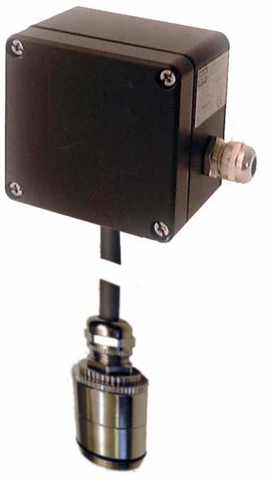
4 Detection Principle The CS21 is operated on the chemosorption principle. The basic element is a sensor, which is different depending on the application and the gas to be monitored. As long as there is no gas in the ambient air, the internal resistance of the sensor is rather high. As soon as gas is adsorbed at the sensor surface, the internal resistance is reduced. The change in resistance is the measure for the gas concentration and is converted to a standardized current signal ( ma or ma) by the integrated electronic circuit. The chemosorption principle has proven a good long-term stability and, depending on the sensor design, a good selectivity. Operational Notes Before shipment, the CS21 passes a function and display test, being calibrated with suitable test gases. This does not, however, overrule the obligation to arrange for another function test after putting the transmitter in operation. Design The design of the CS21 is shown in Fig. 2. The sensor is mounted in the sensor support (pos. 5). The gas enters the sensor chamber through the diffusion inlet (pos. 6). The casing (pos. 2) includes a resin encapsulated p.c. board with electronic components. The electronic circuit on the p.c. board converts the measurement signal into the output of ma or ma, which is supplied to the evaluation unit by means of the transmitter cable. CS21 Design 1. Casing top 2. Casing bottom 3. Type label 4. EMC cable gland (PG 11) 5. Sensor support 6. Diffusion inlet Fig. 2 4
5 Poti N CS21 Schematic Poti 0 (option) Poti C Test Contacts Resin Fuse Terminals EMC cable gland-pg 11 Sensor Fig. 3 Mounting Position of CS21 It is essential to exactly know the ambient conditions, which have to be taken into consideration before deciding on the mounting position. To achieve representative measurement results, take care of the room ventilation and the gas density, the danger highlights. Install the CS21 at a place where the gases pass the sensor even in case of bad ventilation. If necessary, use a smoke cartridge to check. Furthermore, take the following into consideration as well: Ambient temperature, Rain, hose water, dripping water, condensate and Dust in the atmosphere. The CS21 is to a great extent protected against the entering of water and dust (IP 54). Special accessories are available to provide additional protection for very difficult conditions. Please contact GfG for detailed information.! Warranty may be voided, if the transmitter is exposed to ambient conditions that were unknown to GfG during planning, production or delivery. When deciding on the mounting position, make sure that the transmitter is easily accessible for service and calibration. Mount the transmitter with the sensor support showing to the floor, to facilitate service and maintenance. A different mounting position, however, does not affect the sensor accuracy. 5
6 Mounting The CS21 is connected to the controller according to the connection diagram (please also refer to the terminal diagram of your GMA controller). For mounting the transmitter remove the four special screws and take the casing top off. Fix the casing by means of two screws through the relevant borings. Inside the casing you see a resin encapsulated p.c. board with electronic components. The optional potentiometer 0 is factory-set and MUST NOT be turned.! The CS21 is not certified for use in hazardous areas. Installation of Electrical Connections A specialist must do procurement of cable and electrical connections only, obeying the applicable regulations. Depending on model or operation of the transmitter CS21, installation has to be done using a shielded 3-core 18 AWG cable. Connections Terminals Resin Terminals Resin red red Sensor green yellow Signall Ground Voltage Supply EMC-PG green brown white blue Sensor Signall Ground Voltage Supply EMC-PG 11 Sensor Connecting Wire, max. 2 m External Sensor Fig. 4 The supply voltage for the transmitter (terminal 4) is V DC. Once the installation is completed, close the casing top and fix it with the screws. Note: Shielding is done over the EMC cable screwing. 6
7 Transmitter Casing Shield Transmitter Cable EMC Screwing The shield is to be connected to the transmitter casing by means of the cable screwing. Fix the shield as shown in above sketch. Fig. 5 Putting in Operation Once the CS21 is installed, a skilled person can put it in operation. Before shipment, the CS21 has been calibrated and tested after a running-in time of several days. You do not have to wait for so long, but once you have started your new CS21, the chemosorption sensor needs a certain running-in time of approx minutes before you can check the sensitivity. Should you notice that a re-calibration is required, allow the transmitter to warm up for about 4 hours. Check of electrical zero point The CS21 is calibrated and tested before shipment. Certain deviations, however, are possible due to transport, mounting and ambient conditions. Inside the CS21 there are two test contacts (fig. 3) to check the electrical output signal. The voltage at the test contacts can be measured by means of a voltmeter. After the warm-up time of approx. 30 minutes, the signal must be approx. 197 mv, this corresponds to an output current of 4 ma ( ma interface). In case of deviation it is possible to re-adjust the value by turning potentiometer 0 Check of Electrical Dead Band (Should not be adjusted without GFG authorization) The CS21 is calibrated and tested before shipment. Certain deviations, however, are possible due to transport, mounting and ambient conditions. Inside the CS21 there are two test contacts (fig. 3) to check the electrical output signal. The voltage at the test contacts can be measured by means of a voltmeter. After the warm-up time of approx. 30 minutes, the signal must be approx. 200mV for zero gas *. This corresponds to an output current of 0.2 ma ( ma interface) respectively 4 ma ( ma interface). In case of deviation it is possible to re-adjust the value by turning potentiometer N. Alternatively, for example when using a GMA controller, you can check the transmitter signal at the controller. After the warm-up time of approx. 30 minutes, you can read the zero point voltage at the controller resp. check with a voltmeter (please read the operation manual of your GMA controller). In case of deviation you can correct it at the controller. Check of Sensitivity To check the sensitivity of the CS21 fix a calibration adapter to the diffusion inlet of the transmitter. Then select a suitable test gas, taking into consideration, which gas has been used for initial calibration of the transmitter. You can see this information from the test report. The test gas concentration should be at least 20 % above the second alarm threshold. The basic adjustment can be seen from the test report. * In this case, zero gas is not fresh air but test gas with 30 ppm of the gas to be monitored in air 7
8 Use a multimeter to check the output signal by measuring the voltage at the test contacts. The voltage is proportional to the output current. 200mV correspond to an output current of 0.2 ma ( ma interface) resp. 4 ma ( ma interface). 1000mV correspond to an output current of 1 ma ( ma interface) resp. 20 ma ( ma interface). In case of deviation you can correct the value by turning potentiometer C. Alternatively, for example when using a GMA controller, you can check the transmitter signal at the GMA. After the warm-up time of approx. 30 minutes you can read the signal voltage at the controller or check it with a voltmeter (please read the operation manual of your GMA). Should you notice a deviation, you can correct it at the GMA.! Do not use a test gas with a balance of nitrogen You must use an inline humidifier, and a ½ l/min. valve with test gas. For measurement accuracy it is important to use the end range gas to calibrate the CS 21. Adhere to the following procedure for checking the sensitivity: Suppress alarm transmission. Put calibration adapter on transmitter. Supply test gas to CS21 without pressure and with a flow rate of approx. 0.5 l/min. Within about 2-5 minutes a voltage corresponding to the gas concentration can be measured at the test contacts. Alternatively the calibration can be checked at the GMA controller. Is the measured value equivalent to the calibration curve? yes no Re-adjust calibration by turning potentiometer C. Alternatively: Re-adjust calibration point at GMA controller. Please refer to the operation manual of your GMA controller. Disconnect test gas and calibration adapter. Disconnect alarm suppression. 8
9 Service This function checks: Check with alarm gas concentration Check of zero point and sensitivity (calibration) Check of response time Check of gas sampling and gas processing system (if any) Check of alarm signal activation Check of failure alarm An expert, who has to report the result in written form, must do the check. Generally the calibration intervals should not exceed 16 weeks. The function check is to be done before putting the system in operation, and it has to be done at least once a year. Maintenance and Inspection Maintenance and inspection mean measures that ensure the planned status of the gas monitoring system. The CS21 does not require special maintenance, a few points should be obeyed yet. Depending on the ambient conditions, gas monitoring systems may show a different behavior. It is important, therefore, to do a visual check every day, particularly during the first few days after putting in operation. Check of gas processing system and filters (if any). Check of gas supply for soiling or obstacles (for correct measurement the gas supply to the sensor must not be blocked). Sensors are subject to ageing and exhausting. Depending on their type and on their exposure to gas they are more or less used up, so a sensitivity check can only be done with a suitable test gas after certain periods. The sensitivity calibration is an expert calibration and is usually done by GfG service or by authorized persons. Trouble Shooting Failure Reason Solution Zero point cannot be adjusted Faulty sensor Replace sensor Full scale value cannot be set Faulty sensor Replace sensor Output current has fallen to 0 ma Spare Parts Defective fuse Defective electronics Faulty sensor Cable cut Replace fuse Replace p.c. board Replace sensor Re-fix connection Part No. Casing top Accessories Part No. Screw-on calibration adapter
10 Connection Diagram CS21 / Built-in Sensor Built-in Sensor MK red green yellow white green brown Connect shield to Cable Gland ma GND 20V / 24V GMA GMA GMA Motherboard from 1997 (blue) GMA Motherboard until 1996 (no color) GMA GMA GMA81 (A)
11 Connection Diagram CS21 / External Sensor MK External Sensor brown green white white green brown Connect shield to Cable Gland ma GND 20V / 24V GMA GMA GMA Motherboard from 1997 (blue) GMA Motherboard until 1996 (no color) GMA GMA GMA81 (A)
12 Technical Data Transmitter CS21 Type: CS21 Sensor Type (MK): see test report Gas: See test report Range: see test report Gas Supply: Diffusion Detection Principle: Chemosorption (CS) Supply Voltage: V DC Output Current: mA (4kΩ) or 4..20mA (200Ω) Response Time t A : < 14 s (depending on gas) Typical Sensor Life: > 5 years Climate Conditions Operational Temperature: C Humidity: % r. h., non condensing Atm. Pressure: hpa Casing Material: Aluminum Protection: IP 54 Cable Gland: PG 11 screwing, max. cross section 3 x 1.5 mm2 Transmitter Cable: Shielded cable - #18/3 shielded or Belden 8770 equal Dimensions: 100 x 100 x 57 mm (WxHxD) Weight: approx. 370 g 12
13
14
15
16 1194 Oak Valley Drive, Suite 20 Ann Arbor, Michigan United States of America Phone: (800) or (734) Fax (734) Website: GfG reserves the right of modification JA 7004-CS21
Transmitter CS 21 Operation Manual
 Transmitter CS 21 Operation Manual 1194 Oak Valley Drive, Suite 20, Ann Arbor, MI 48108 800-959-0573 734-769-1888 Content Page For your Safety 3 General Description 3 Detection Principle 4 Operation 4
CC Operation Manual Oak Valley Drive, Suite 20, Ann Arbor, Michigan USA fax
 CC 0238 Operation Manual 1194 Oak Valley Drive, Suite 20, Ann Arbor, Michigan 48108 USA www.gfg-inc.com 800-959-0329 734-769-0573 734-769-1888 fax Content Page For your Safety 3 General Description 3 Detection
Operation Manual. Transmitter IR 24. Models MWG 2491 / MWG Worldwide Supplier of Gas Detection Solutions
 Worldwide Supplier of Gas Detection Solutions Gesellschaft für Gerätebau mbh P.O. Box 440164 D-44390 Dortmund Phone: +49-231-56400-0 Fax: +49-231-516313 E-Mail: info@gfg-mbh.com Internet: www.gfg.biz Transmitter
RAM 4021-DPX Operation Manual
 RAM 4021-DPX Operation Manual Worldwide Manufacturer of Gas Detection Solutions TABLE OF CONTENTS ABL 4021-DPX / RAM 4021-DPX For Your Safety... 3 Description... 3 Setup Mode... 4 Lights/Alarms... 4 Operation...
LK-SX VOC. Application. Security Advice Caution. Notes on Disposal. Combined sensor mixed gas. Data sheet
 LK-SX VOC Combined sensor mixed gas Data sheet Subject to technical alteration Issue date: 24.08.2015 Application The sensor detects air quality in ventilation ducts. A stronger output signal of the sensor
RAM Operation Manual. Worldwide Manufacturer of Gas Detection Solutions
 RAM 4021 Operation Manual Worldwide Manufacturer of Gas Detection Solutions TABLE OF CONTENTS RAM 4021 For Your Safety... 2 Description.... 2 Setup Mode.... 2 Lights/Alarms.... 3 Operation.... 4 Calibration....
LK-SX CO 2 +VOC. Application. Security Advice Caution. Notes on Disposal
 LK-SX CO 2 +VOC Sensor for detection of carbon dioxide (CO 2) and mixed gas content in air ducts Data sheet Subject to technical alteration Issue date: 24.08.2015 Application For detection of CO2 and VOC.
RAM Operation Manual
 RAM 4021-1 Operation Manual Worldwide Manufacturer of Gas Detection Solutions TABLE OF CONTENTS RAM 4021-1 For Your Safety... 2 Description... 2 Setup Mode... 3 Lights/Alarms... 3 Operation... 4 Calibration...
MODEL GT820 OXYGEN SENSOR
 INSTRUCTION MANUAL MODEL GT820 OXYGEN SENSOR 70046 The information and technical data disclosed by this document may be used and disseminated only for the purposes and to the extent specifically authorized
RAM Operation Manual. Worldwide Manufacturer of Gas Detection Solutions
 RAM 4021 Operation Manual Worldwide Manufacturer of Gas Detection Solutions TABLE OF CONTENTS RAM 4021 For Your Safety... 2 Description.... 2 Setup Mode.... 2 Lights/Alarms.... 3 Operation.... 4 Calibration....
RAM 4021-PR. Operation Manual. Worldwide Manufacturer of Gas Detection Solutions
 RAM 4021-PR Operation Manual Worldwide Manufacturer of Gas Detection Solutions TABLE OF CONTENTS RAM 4021-PR For Your Safety... 2 Description.... 2 Setup Mode.... 2 Lights/Alarms.... 3 Operation.... 4
Sensoric 4-20 ma Transmitter Board Operation Manual
 Sensoric 4-20 ma Transmitter Board Operation Manual 1 Content Features Operation Manual Technical Data Mechanical Dimensions Remarks & Contact information 2 Features Soldered sensor cell (non replaceable)
Instruction Manual Differential Pressure Transmitter
 DE61 Instruction Manual Differential Pressure Transmitter Table of Contents 1. Safety Instructions 2. Intended Applications 3. Product Description and Functions 4. Installation 5. Commissioning 6. Maintenance
High-performance submersible pressure transmitter For level measurement Model LH-10
 Electronic pressure measurement High-performance submersible pressure transmitter For level measurement Model LH-10 WIKA data sheet PE 81.09 Applications Level measurement in rivers and lakes Deep well
High-performance submersible pressure transmitter For level measurement Model LH-10
 Electronic pressure measurement High-performance submersible pressure transmitter For level measurement Model LH-10 WIKA data sheet PE 81.09 Applications Level measurement in rivers and lakes Deep well
Instruction and Maintenance Manual
 Instruction and Maintenance Manual GRYF OXY ZM 02/100/2 E Contact GRYF HB, spol. s r.o. Cechova 314 Havlickuv Brod 580 01 tel.: +420 569 426 627 fax: +420 569 426 627 www.gryf.eu ver.: 11.2.2015 OEM module
Technical Data Sheet MF010-O-LC
 Technical Data Sheet MF010-O-LC - 1 - 1. Properties The oxygen measuring system MF010-O-LC determines the oxygen content in gas mixtures up to a temperature of 250 C. It is particularly suitable for the
GasSense NDIR User Manual
 INDEX INDEX... 1 1. OVERVIEW... 2 2. TECHNICAL DATA... 3 3. SPECIFICATIONS... 4 4. PRODUCT DESCRIPTION... 5 4.1 Mechanical details... 5 4.2 Piping... 7 4.3 Connections... 7 5. INSTALLATION... 10 6. CALIBRATION
MEGAS 2.0. Gas analysis with direct C-Level Calculation and Bus-Connection. Data sheet
 Data sheet MEGAS 2.0 Gas analysis with direct C-Level Calculation and Bus-Connection Mesa Industrie-Elektronik GmbH Neckarstraße 19, D-45768 Marl info@mesa-gmbh.de +49 (0) 2365-97 45 1-0 +49 (0) 2365-97
Intelligent SUNTEX DC-5310(RS) Dissolved Oxygen Transmitter
 Dissolved Oxygen Transmitter") Intelligent SUNTEX DC-5310(RS) Dissolved Oxygen Transmitter Overview C % ppm 4~20mA Analog Output ppb Power Supply 100~240 VAC mg/l Dimensions 96 x 96 x 132mm RS-485 Digital Output (for DC-5310-RS only)
Intelligent SUNTEX DC-5310(RS) Dissolved Oxygen Transmitter Overview C % ppm 4~20mA Analog Output ppb Power Supply 100~240 VAC mg/l Dimensions 96 x 96 x 132mm RS-485 Digital Output (for DC-5310-RS only)
1 Overview. Pressure Measurement Single-range transmitters for general applications. 1/22 Siemens FI
 Siemens AG 06 SITRANS LH00 Transmitter for hydrostatic level Overview Function U const. p U I EM The pressure transmitter SITRANS LH00 is a submersible sensor for hydrostatic level measurement. The pressure
1 Overview. Pressure Measurement Single-range transmitters for general applications. 1/22 Siemens FI US Edition
 Siemens AG 07 SITRANS LH00 Transmitter for hydrostatic level Overview Function U const. p U I EM The pressure transmitter SITRANS LH00 is a submersible sensor for hydrostatic level measurement. The pressure
210 Series Transmitter with External Electrochemical Sensor
 210 Series Transmitter with External Electrochemical Sensor INSTRUCTIONS Installation and Operation of the AMC-210 Series Transmitter with External Electrochemical Sensor IMPORTANT: Please read these installation
MANUAL KPS Pressure Control Valve
 TetraTec Instruments GmbH Gewerbestrasse 8 71144 Steinenbronn Deutschland E-Mail: info@tetratec.de Tel.: 07157/5387-0 Fax: 07157/5387-10 MANUAL Pressure Control Valve *** VERSION 1.0 *** Update: 17.11.2006
O3 3E 1 F Gas Sensor Module
 Product Information Pack O3 3E 1 F Gas Sensor Module (Ozone) CONTENTS Product Data Sheet Product Specification 2 Poisoning and Cross Sensitivities 3 Operating Instructions Introduction 4 Electrostatic
Pressure Measurement Single-range transmitters for general applications
 Siemens AG 07 Overview Function U const. p U I EM Sensor Connection for auxiliary power supply Vent pipe with humidity filter Protective conductor connection/ Equipotential bonding Diaphragm The pressure
RAM 4021 Operation Manual
 RAM 4021 Operation Manual Worldwide Manufacturer of Gas Detection Solutions TABLE OF CONTENTS RAM 4021 For your safety...3 Description...3 Set-up mode...4 Annunciator lights/alarms...4 Operation...5 Calibration...6
Electro-Pneumatic Converter YT-940 SERIES
 Electro-Pneumatic Converter YT-940 SERIES PRODUCT MANUAL VERSION 1.00 Contents 1. Introduction 3 1.1 General information for the users. 3 1.2 Manufacturer Warranty 3 1.3 Explosion Proof Warning. 4 2. Product
Operating Instructions
 Operating Instructions Sensors Type 705 H 2 S Sensor and Transmitter for Electrochemical Cells Ul Certified HELPING TO MAKE A SAFER WORLD Ensure that you read and understand these operating instructions
Instruction and Maintenance Manual
 Instruction and Maintenance Manual GRYF OXY Z 02/100/2 E Contact GRYF HB, spol. s r.o. Cechova 314 Havlickuv Brod 580 01 tel.: +420 569 426 627 fax: +420 569 426 627 Czech Republic www.gryf.eu Technical
Best Practice Guide, Servomex 2700
 For full installations details refer to the. Best Practice Guide, Servomex 2700 Mounting: General Guidelines: Servomex 2700 Control Units and air supplies (utilities units) should, ideally, be mounted
JUMO dtrans O2 01 Two-wire Transmitter for dissolved oxygen (DO)
") Data Sheet 202610 Page 1/12 JUMO dtrans O2 01 Two-wire Transmitter for dissolved oxygen (DO) with optional terminal box or operating unit Type 202610 Two-wire transmitter JUMO dtrans O2 01 Brief description
Data Sheet 202610 Page 1/12 JUMO dtrans O2 01 Two-wire Transmitter for dissolved oxygen (DO) with optional terminal box or operating unit Type 202610 Two-wire transmitter JUMO dtrans O2 01 Brief description
Installation, operating and maintenance Instructions for Seemag bypass level indicator
 Issue: S Date: 05-09-14 Type G35 General information The Seetru bypass magnetic level indicator, abbreviate SEEMAG, serves to show the filling level of fluids in tanks, basins, tubes etc. The Seemag operates
User Manual. PolyGard AT-1130 V3. Electrochemical Nitrogen Dioxide Transmitter. July, 2011
 PolyGard AT-30 V3 Electrochemical Nitrogen Dioxide Transmitter User Manual July, 20 January 04, 206 Revision Specifications subject to change without notice. USA 6004 Page 2 of 3 General Overview... 3
Operating Instructions Temperature Measuring System MF420-5T-100
 Operating Instructions Temperature Measuring System Dnhqdhnjah MF420-5T-100 Dmsklakla Read before use! Observe all safety instructions! Keep for future reference! Fon +49/7221/64103 Fax +49/7221/17103
Series 6517 Katharometers. The ideal equipment for Process Monitoring and Control. Robust no moving parts. Designed for continuous industrial use
 Data sheet Katharometers The ideal equipment for Process Monitoring and Control Designed for continuous industrial use Long working life Suitable for flammable gases CENELEC certified (ATEX) to EExia IIC
PULSAR 5000 SERIES OPERATING & INSTALLATION INSTRUCTIONS SERIES 5000 PLEASE READ CAREFULLY BEFORE INSTALLING
 PULSAR 5000 SERIES OPERATING & INSTALLATION INSTRUCTIONS SERIES 5000 PLEASE READ CAREFULLY BEFORE INSTALLING Please Note: Ranges above 500mbar are designed and manufactured in accordance with sound engineering
Model PDT Dewpoint Transmitter
 Model PDT Dewpoint Transmitter Instruction Manual Alpha Moisture Systems Alpha House 96 City Road Bradford BD8 8ES England Tel: +44 1274 733100 Fax: +44 1274 733200 email: mail@amsytems.co.uk web: www.amsystems.co.uk
INSTALLATION & MAINTENANCE INSTRUCTIONS
 DESCRIPTION / IDENTIFICATION The QBX series valve uses Proportion-Air closed loop technology for Pressure control. It gives an output pressure proportional to an electrical command signal input. The QB1X
Visualize Nitrogen Gas Consumption
 Air Flow Monitor EWA2 SERIES Conforming to EMC Directive (all models) & Pressure Equipment Directive (AEWA2150/2200 only) Visualize Nitrogen Gas Consumption Small pipe size as Well as Air Consumption!
GASGUARD VENT LINE3 Ammonia Sensor OPERATING & INSTALLATION MANUAL
 GASGUARD VENT LINE3 Ammonia Sensor OPERATING & INSTALLATION MANUAL Operating and Installation Manual Warning Use this product only in the manner described in this manual. If the equipment is used in a
AUTOMATIC TIRE INFLATOR # MW-60, MW-60-4WAY & MW-64HP
 USER MANUEL AUTOMATIC TIRE INFLATOR # MW-60, MW-60-4WAY & MW-64HP TIRE EQUIPMENT MANUFACTURER 1.866.409.RACK WWW.MARTINSINDUSTRIES.COM info@martinsindustries.com PARTS Verify that the following components
INSTRUCTION MANUAL MP4AR Remote Convection Gauge Range: 1 x 10⁻³ Torr to 1 x 10+3 Torr
 INSTRUCTION MANUAL MP4AR Remote Convection Gauge Range: 1 x 10⁻³ Torr to 1 x 10+3 Torr A DIVISION OF THE FREDERICKS COMPANY 2400 PHILMONT AVE. HUNTINGDONVALLEY, PA 19006 PARTS LIST 1 3 4 2 # QTY ITEM DESCRIPTION
Instruction Manual Contact Pressure Vacuum Gauge
 MS10 Instruction Manual Contact Pressure Vacuum Gauge Table of Contents 1. Safety Instructions 2. Intended Applications 3. Product Description and Functions 4. Installation 5. Commissioning 6. Maintenance
better measurement Simply a question of SCHMIDT Flow Sensor SS The cost-effective alternative in pressurised systems up to 10 bars.
 Simply a question of better measurement SCHMIDT Flow Sensor SS 20.261 The cost-effective alternative in pressurised systems up to 10 bars. Compressed air technology Industrial processes A cost analysis
Instruction Manual AD 1000 / BA 1000 Absolute Pressure Sensor
 Instruction Manual AD 1000 / BA 1000 Absolute Pressure Sensor halstrup-walcher GmbH Stegener Straße 10 D-79199 Kirchzarten Phone: +49 (0) 76 61/39 63 0 Fax: +49 (0) 76 61/39 63 99 E-Mail: info@halstrup-walcher.com
Malema Sensors M-2700 Integrated Ultrasonic Flow Meter
 Malema Sensors M-2700 Integrated Ultrasonic Flow Meter Operating Instructions TABLE OF CONTENTS Introduction............... 3 Storage and Handling........... 4 Installation Instructions........... 4 Start
97C COMPRESSOR KIT 12V PART NO C COMPRESSOR KIT 24V PART NO C COMPRESSOR KIT PART NO
 97C COMPRESSOR KIT 12V PART NO. 00097 97C COMPRESSOR KIT 24V PART NO. 02497 98C COMPRESSOR KIT PART NO. 00098 97C 98C IMPORTANT: It is essential that you and any other operator of this product read and
User Manual. µ-gard MD Electrochemical Carbon Monoxide Transmitter Serial No. MD April, 2011
 µ-gard Electrochemical Carbon Monoxide Transmitter Serial No. MD01-002 User Manual April, 2011 Page 2 1 Intended Use... 3 2 Functional Description... 3 2.1 Transmitter... 3 2.2 Sensor... 3 3 Installation...
GG-VL2-NH3 AMMONIA VENT LINE SENSOR. Installation and Operation Manual
 GG-VL2-NH3 AMMONIA VENT LINE SENSOR Installation and Operation Manual 2 GG-VL2-NH3 Warning Use this product only in the manner described in this manual. If the equipment is used in a manner not specified
Operation Manual. Rev. C LPT Low Power Transmitter (Electrochemical Sensor)
") Operation Manual Rev. C 2014.04 LPT Low Power Transmitter (Electrochemical Sensor) www.critical-environment.com LPT - Operation Manual Rev. C 2014.04 TABLE OF CONTENTS 1 POLICIES...4 1.1 Important Note...4
Operation Manual Rev. C 2014.04 LPT Low Power Transmitter (Electrochemical Sensor) www.critical-environment.com LPT - Operation Manual Rev. C 2014.04 TABLE OF CONTENTS 1 POLICIES...4 1.1 Important Note...4
dtrans O2 01 Two-wire Transmitter for dissolved oxygen (DO)
") JUMO GmbH & Co. KG Delivery address:mackenrodtstraße 14, 36039 Fulda, Germany Postal address: 36035 Fulda, Germany Phone: +49 661 6003-0 Fax: +49 661 6003-607 e-mail: mail@jumo.net Internet: www.jumo.net
JUMO GmbH & Co. KG Delivery address:mackenrodtstraße 14, 36039 Fulda, Germany Postal address: 36035 Fulda, Germany Phone: +49 661 6003-0 Fax: +49 661 6003-607 e-mail: mail@jumo.net Internet: www.jumo.net
444C DUAL PERFORMANCE VALUE PACK
 (Chrome) PART NO. 44432 IMPORTANT: It is essential that you and any other operator of this product read and understand the contents of this manual before installing and using this product. SAVE THIS MANUAL
Climatic Independent Level Sensor LAR
 1 Product Information LAR-361 LAR-761 Climatic Independent Level Sensor LAR Application / Specified usage Authorizations Hydrostatic level measurement in humid ambiance Special applicable for exterior
Hand-held pressure calibrator with integrated pump Model CPH6600
 Calibration technology Hand-held pressure calibrator with integrated pump Model CPH6600 WIKA data sheet CT 16.01 Applications Calibration service companies and service industry Measurement and control
SANP ACTING RELAYS YT-520/525/530 SERIES
 SANP ACTING RELAYS YT-520/525/530 SERIES PRODUCT MANUAL VERSION 1.02 Contents 1. Introduction 3 1.1 General information for the users. 3 1.2 Manufacturer Warranty 3 2. Product Description.. 4 2.1 General..
HUMOR 20. High-precision Humidity Calibrator HUMOR 20. Operation
 High-precision Humidity Calibrator The role of humidity calibrations that are accurate, reproducible, and documentable is becoming more and more important. ISO quality guidelines and regulations according
400C & 450C DUAL PERFORMANCE VALUE PACKS
 (Chrome) PART NO. 40013 (Silver) PART NO. 45012 (Chrome) PART NO. 45013 IMPORTANT: It is essential that you and any other operator of this product read and understand the contents of this manual before
User Manual. PolyGard DT V4. Electrochemical Carbon Monoxide Transmitter Serial No. DT December, 2008
 PolyGard DT5-1112 V4 Electrochemical Carbon Monoxide Transmitter Serial No. DT5-1112 User Manual December, 2008 August 29, 2017 Revision Specifications subject to change without notice. USA 170829 Page
GAS FUEL VALVE FORM AGV5 OM 8-03
 ALTRONIC AGV5 OPERATING MANUAL GAS FUEL VALVE FORM AGV5 OM 8-03 WARNING: DEVIATION FROM THESE INSTALLATION INSTRUCTIONS MAY LEAD TO IMPROPER ENGINE OPERATION WHICH COULD CAUSE PERSONAL INJURY TO OPERATORS
Operation and Maintenance Manual
 Operation and Maintenance Manual GDS 49 Remote 4 20mA Sensor Transmitter for Toxic Gases GDS Corp. 1245 Butler Road League City, TX 77573 409 927 2980 409 927 4180 (Fax) www.gdscorp.com CAUTION: FOR SAFETY
Columbus Instruments
 0215-003M Portable O 2 /CO 2 /CH 4 Meter User s Manual Columbus Instruments 950 NORTH HAGUE AVENUE TEL:(614) 276-0861 COLUMBUS, OHIO 43204, USA FAX:(614) 276-0529 1 www.colinst.com TOLL FREE 1-800-669-5011
Alphasense 4-20 ma transmitters offer convenience and easy maintenance for toxic sensors:
 ALPHASENSE USER MANUAL Page 1 4-20mA Transmitter for Toxic Sensors UMTOX-1 Issue 4 1 INTRODUCTION The Transmitter PCB includes circuitry for a three electrode toxic sensor to convert the µa output signal
Datasheet: K-30 ASCII Sensor
 Datasheet: K-30 ASCII Sensor The K30 ASCII sensor is a low cost, infrared and maintenance free transmitter module intended to be built into different host devices that require CO2 monitoring data. The
Oxymax COS61/COS61D. Technical Information
 Technical Information Oxymax / Dissolved oxygen measurement Optical sensor acc. to the fluorescence quenching principle, with or without Memosens protocol Application The continuous measurement of the
200 PSI COMPRESSORS - MODEL NUMBERS
 200 PSI COMPRESSORS - MODEL NUMBERS 380C AIR COMPRESSOR KIT PART NO. 38033 480C AIR COMPRESSOR KIT PART NO. 48043 380C 480C IMPORTANT: It is essential that you and any other operator of this product read
CSA Sample Draw Aspirator Adapter Operator s Manual
 30-0951-CSA Sample Draw Aspirator Adapter Operator s Manual Part Number: 71-0367 Revision: 0 Released: 4/30/15 www.rkiinstruments.com WARNING Read and understand this instruction manual before operating
RGC-IR Remote Gas Calibrator for IR400
 Remote Gas Calibrator for IR400 The information and technical data disclosed in this document may be used and disseminated only for the purposes and to the extent specifically authorized in writing by
OXY 3690 MP. Measuring transducer for air oxygen
 T02.0.4X.6C-11 Measuring transducer for air oxygen OXY 3690 MP as of version V1.3 operating manual OXY 3690 MP - LO WEEE-Reg.-Nr. DE 93889386 GHM Messtechnik GmbH Standort Greisinger Hans-Sachs-Str. 26
* * Data Sheet and Operating Manual. Digital manometer ME01 ## # 87 # HL S#### Dust explosion protection Zone 22.
 *09005087* DB_BA_EN_ME01_S Rev.A 12/16 *09005087* d e v e l o p i n g s o l u t i o n s Data Sheet and Operating Manual ME01 Digital manometer Table of Contents ME01 ## # 87 # HL S#### Dust explosion protection
FTC130 Transmitter. Operating Manual
 Seite 1 von 11 FTC130 Transmitter Fast Thermal Conductivity Analyzer Operating Manual 1.09KD180724CWI1V05 Messkonzept GmbH Seite 2 von 11 1. Intended Use... 3 2. Description... 4 3. Measuring gases and
FLAMMABLE GAS SENSOR/TRANSMITTER
 FLAMMABLE GAS SENSOR/TRANSMITTER Plant safety protection for flammable gases. F E A T U R E S Fixed gas monitoring for point source hazards and perimeter protection in arduous duty and exposed locations.
420C AIR COMPRESSOR KIT PART NO C AIR COMPRESSOR KIT PART NO
 420C AIR COMPRESSOR KIT PART NO. 42042 460C AIR COMPRESSOR KIT PART NO. 46043 420C 460C IMPORTANT: It is essential that you and any other operator of this product read and understand the contents of this
BI-680 Online Dissolved Oxygen Controller Instruction Manual
 BI-680 Online Dissolved Oxygen Controller Instruction Manual BANTE INSTRUMENTS CO., LTD BI-680 Online Dissolved Oxygen Controller 1 Introduction Thank you for selecting the BI-680 online dissolved oxygen
Instruction Manual Differential Pressure Transmitter
 DE13 Instruction Manual Differential Pressure Transmitter Table of Contents 1. Safety Instructions 2. Intended Applications 3. Product Description and Functions 4. Installation 5. Commissioning 6. Maintenance
ZIRCONIA OXYGEN DETECTOR SERVICE MANUAL
 Service Manual ZIRCONIA OXYGEN DETECTOR SERVICE MANUAL TYPE: ZFK 3, 4, 7 TN5A08a-E CONTENTS. PREFACE.... MEASUREMENT PRINCIPLE... 3. ADJUSTMENT...3 3. Zero (Air) Adjustment... 3 3. Span Adjustment... 3
Operating Instructions Part No
 DIGITAL AUTOMATIC TYRE INFLATOR Operating Instructions Part No. 11.0545 Thank you for selecting this Jamec Pem Automatic Tyre Inflator. Please read this manual before carrying out any installation or service
User Manual. asense VAV. CO 2 / temperature sensor with built-in general purpose controller
 Gas and Air Sensors User Manual asense VAV CO / temperature sensor with built-in general purpose controller General The IAQ-sensor product asense VAV is used to measure indoor air carbon dioxide concentration
ISM-3 User Manual PBI D 04/2013
 ISM-3 User Manual PBI-200114-D 04/2013 ISM-3 EN User Manual ISM-3 User Manual Published by: Dansensor A/S Rønnedevej 18, DK-4100 Ringsted Denmark Tel.: +45 57 66 00 88 Fax: +45 57 66 00 99 E-mail: info@dansensor.com
Operating Instructions Part No
 DIGITAL AUTOMATIC TYRE INFLATOR Operating Instructions Part No. 11.0578 Thank you for selecting this Jamec Pem Automatic Tyre Inflator. Please read this manual before carrying out any installation or service
Installation and Operation Manual
 Installation and Operation Manual WIKA FLR-SBDF / BLR-SBDF Magnetic Level Transmitter (Please retain for future usage) Contact: Gayesco-WIKA USA, L.P. 229 Beltway Green Boulevard Pasadena, TX 77503 www.wika.com
INSTALLATION & MAINTENANCE INSTRUCTIONS DESCRIPTION SPECIFICATIONS. CE (EMC) Compliant
 Compliant") INSTALLATION & MAINTENANCE INSTRUCTIONS DESCRIPTION The QB3 is a closed loop pressure regulator consisting of two solenoid valves, internal pressure transducer, and electronic controls mounted to an integrated
INSTALLATION & MAINTENANCE INSTRUCTIONS DESCRIPTION The QB3 is a closed loop pressure regulator consisting of two solenoid valves, internal pressure transducer, and electronic controls mounted to an integrated
Operation Manual. Pro CO 2 Analyzer. Carbon Dioxide Analyzer. Rev
 Operation Manual Pro CO 2 Analyzer Carbon Dioxide Analyzer Rev. 10.17 Quick Reference Guide READ ENTIRE MANUAL BEFORE USE 1. To switch on, hold the On/Off button until the display powers up. 2. To turn
EPP4 Pressure Regulator Basic G 1/4"
 EPP4 Pressure Regulator Basic G 1/4" Flow Curve 1/4" Dimensions Outlet pressure - bar 9 8 7 6 5 4 3 2 1 0 0 20 40 60 70 80 100 120 Flow rate - Nm 3 /h The male connector adopted on the EPP4 is a standard
100C Air Compressor Kit
 10010 100C Air Compressor (standard mounting bracket, CE Spec) 10014 100C Air Compressor (no leader hose or check valve, CE Spec) 10016 100C Air Compressor (with Omega Bracket, CE Spec) IMPORTANT: It is
with O 2 Controller Instruction Manual
 14500 Coy Drive, Grass Lake, Michigan 49240 734-475-2200 E-mail: sales@coylab.com www.coylab.com Hypoxic Cabinets (In-Vivo / In-Vitro) with O 2 Controller Instruction Manual Index Page Warranty 2 Warnings
RK LEL Sample Draw Aspirator Adapter Operator s Manual
 30-0951RK LEL Sample Draw Aspirator Adapter Operator s Manual Part Number: 71-0017RK Revision: A Released: 6/2/10 www.rkiinstruments.com Product Warranty RKI Instruments, Inc. warrants gas alarm equipment
SPECIFICATIONS PARTICLE SENSOR KS-18F Higashimotomachi, Kokubunji, Tokyo , Japan
 SPECIFICATIONS PARTICLE SENSOR KS-18F 3-20-41 Higashimotomachi, Kokubunji, Tokyo 185-8533, Japan No. 05083-5E 18-01 Printed in Japan Outline The KS-18F is a sensor which uses the light scattering method
Thermal flow sensor TA Di with integrated transducer for measuring mass flow, standard flow rate and air / gas consumption
 Thermal flow sensor TA Di for measuring mass flow, standard flow rate and air / gas consumption Sensor TA Di 16 41.8 ZG1b and TADi 16 41.8 ZG1b/M-Bus U10a/U10M Sensor TA Di 8 ZG3b and TA Di 8 ZG3b/M-Bus
Electrochemical Sensor
 ME3-H2 Electrochemical Sensor Manual (Model:ME3-H2) Zhengzhou Winsen Electronics Technology Co., Ltd ME3-H2 gas sensor ME3-H2 electrochemical sensor detect gas concentration by measuring current based
Appendix D: SOP of INNOVA 1412 Photoacoustic Multi-Gas Monitor. Description and Principle of Operation
 Page 1 of 19 : SOP of INNOVA 1412 Photoacoustic Multi-Gas Monitor Description and Principle of Operation The photoacoustic multi-gas monitor (INNOVA 1412, Innova AirTech Instruments, Denmark) is a highly
Electronic gas volume corrector model DGVC-04
 Electronic gas volume corrector model DGVC-04 1. Introduction The following user s manual gives information about the installation, configuration, usage and storage of the electronic gas volume corrector
Operating instructions Safety Rope Emergency Stop Switches ZB0052 / ZB0053 ZB0072 / ZB0073
 Operating instructions Safety Rope Emergency Stop Switches UK ZB0052 / ZB0053 ZB0072 / ZB0073 7390878 / 02 03 / 2011 Contents 1 Safety instructions...3 2 Installation / set-up...4 2.1 Applications...4
Pressure Transmitters 36 F-27839
 Pressure Transmitters 36 F-27839 SPD310/SPD360 Air Differential schneider-electric.com 37 SPD310/SPD360 SPD310/SPD360 differential pressure transmitters are intended for use in air handling systems for
Model B Wire Wet Oxidant Gas Transmitter. 6 Iron Bridge Drive Unit 1 & 2 Gatehead Business Park
 Model B12-69 2-Wire Wet Oxidant Gas Transmitter Home Office European Office Analytical Technology, Inc. ATI (UK) Limited 6 Iron Bridge Drive Unit 1 & 2 Gatehead Business Park Collegeville, PA 19426 Delph
IMPORTANT SAFETY INSTRUCTIONS
 IMPORTANT SAFETY INSTRUCTIONS CAUTION - To reduce risk of electrical shock: - Do not disassemble. Do not attempt repairs or modifications. Refer to qualified service agencies for all service and repairs.
XMO2. Panametrics Smart Oxygen Analyzer. Applications. Features. bhge.com. An oxygen transmitter for use in:
 XMO2 Panametrics Smart Oxygen Analyzer Applications An oxygen transmitter for use in: Inerting/blanketing liquid storage tanks Reactor feed gases Centrifuge gases Catalyst regeneration Solvent recovery
Inductive Linear Displacement Transducers Model IW 260 Measuring strokes: 80 mm, 170 mm, 240 mm, 360 mm
 Inductive Linear Displacement Transducers Model IW 260 Measuring strokes 80, 170, 240, 360 Document no. IW 100 HE Date 1.07.201 Contactless, robust sensor system Infinite resolution, no hysteresis Calibrated
ME3-HCL Electrochemical sensor
 ME3-HCL Electrochemical sensor Manual (Model:ME3-HCL) Zhengzhou Winsen Electronics Technology Co., Ltd ME3-HCL gas sensor ME3-HCL electrochemical sensor detect gas concentration by measuring current based
Oxymax H COS21. Technical Information. Sensor with long-term stability for frequent sterilization and autoclaving
 Technical Information Oxymax H COS21 Sensor with long-term stability for frequent sterilization and autoclaving Application Process control in enzyme production Control of culture growth Biotechnological