DESIGN AND INSTALLATION GUIDE
|
|
|
- Sharon Hensley
- 6 years ago
- Views:
Transcription


1
2


3 DESIGN AND INSTALLATION GUIDE CORRUGATED STAINLESS STEEL TUBING FUEL GAS* PIPING *Includes Natural Gas and Propane P.O. BOX 9 BLOSSBURG, PA C US THROUGH-PENETRATION PRODUCTS FOR USE IN THROUGH-PENETRATION FIRESTOP SYSTEMS SEE UL FIRE RESISTANCE DIRECTORY 9R81 Rev. 10 January 2014 Ward Manufacturing, LLC. All Rights Reserved. Written in accordance with ANSI-LC 1 the Standard for Fuel Gas Piping Systems Using Corrugated Stainless Steel Tubing. I M P O R T A N T R E A D E N T I R E M A N U A L
4 TABLE OF CONTENTS 1.0 Introduction User Warnings Limitations of Manual Listing of Applicable Codes and Standards Description of Systems and Components System Description WARDFLEX /WARDFLEX II Corrugated Stainless Steel Tubing (CSST)...7 WARDFLEX /WARDFLEX II Fittings Description WARDFLEX /WARDFLEX II Components WARDFLEX /WARDFLEX II Description & Sizes Fittings...10 Mechanical Joints (Male Straight & Reducing, Female Straight & Reducing)...10 Couplings...11 Mechanical Tees (Straight & Reducing, Female Straight & Reducing)...11 Adapter Nut...12 Termination Fittings (Male Indoor and Outdoor, Female Indoor and Outdoor...12 Floor Flange Termination Assemblies Male Protection Devices...13 Striker Plates...13 Stripwound Conduit Pressure Regulators Manifolds Shutoff Valves Other Components...16 Appliance, Meter and Fireplace Stubouts...16 Manifold Bracket...16 Right Angle Mounting Bracket...17 Gas Outlet Box...17 Quick Connects...17 Bonding Clamps System Configuration and Sizing System Overview Introduction System Design System Configurations Introduction Series Systems Parallel Systems Dual Pressure Systems Hybrid Systems Elevated Pressure System System Sizing Introduction Longest Length Method...21 Low Pressure Parallel System Example...22 Low Pressure Series System Example...23 Dual Pressure Parallel System...24 Hybrid System Example Summation Sizing Method...26 Low Pressure Example Wardflex Sizing Software Installation Practices General Installation Practices...28 Bend Radius...28 Chemicals to Avoid Fitting Assembly WARDFLEX /WARDFLEX II Stepsaver Fitting WARDFLEX /WARDFLEX II Fitting Reassembly Tubing Routing Vertical Runs Horizontal Runs Clearance Holes and Notching Concealed Locations For Fittings Modification to Existing System Outdoor Installations Fire Rated Construction...34 Firestop Listings Protection Introduction Striker Plates Stripwound Metal Conduit Installation in Insulated Walls Meter-Connections Unsupported Meters Self Supported Meter...42
5 TABLE OF CONTENTS 4.6 Appliance Connections Moveable Appliances Non-Moveable Appliance Outdoor Appliances-Barbeque Grill and Gas Light Connection Special Applications...45 Roof Top Installations...45 Infared Heaters...46 Pad Mounted Gas Appliances Gas Fireplaces Manifold Station Pressure Regulators Installation Requirements Regulator Venting Requirements...51 Vent Lines Regulator Adjustment Over Pressurization Protection Underground Installations General Information...52 Burial Depths and Conduit Termination Height CSST Electrical Bonding Inspection, Repair and Replacement Minimum Inspection Requirements (Checklist) Repair/Replacement of Damaged Tubing Testing Pressure Testing and Inspection Procedure Sizing Tables (Natural and LP) Table of Contents Natural Gas-Low Pressure Table A-1 Natural Gas-Low Pressure 0.5 PSI or less and Pressure Drop of 0.5 in.wc...60 Table A-2 Natural Gas-Low Pressure 0.5 PSI or less and Pressure Drop of 1.0 in.wc...60 Table A-3 Natural Gas-Low Pressure 0.5 PSI or less and Pressure Drop of 1.5 in.wc...61 Table A-4 Natural Gas-Low Pressure 0.5 PSI or less and Pressure Drop of 2.0 in.wc...61 Table A-5 Natural Gas-Low Pressure 0.5 PSI or less and Pressure Drop of 2.5 in.wc...62 Table A-6 Natural Gas-Low Pressure 0.5 PSI or less and Pressure Drop of 3.0 in.wc...62 Table A-7 Natural Gas-Low Pressure 0.5 PSI or less and Pressure Drop of 4.0 in.wc...63 Table A-8 Natural Gas-Low Pressure 0.5 PSI or less and Pressure Drop of 5.0 in.wc...63 Table A-9 Natural Gas-Low Pressure 0.5 PSI or less and Pressure Drop of 6.0 in.wc Natural Gas-Elevated Pressure Table A-10 Natural Gas-Elevated Pressure 1.0 PSI and Pressure Drop of 13.0 in.wc...65 Table A-11 Natural Gas-Elevated Pressure 2.0 PSI and Pressure Drop of 1.0 PSI...65 Table A-12 Natural Gas-Elevated Pressure 2.0 PSI and Pressure Drop of 1.5 PSI...66 Table A-13 Natural Gas-Elevated Pressure 5.0 PSI and Pressure Drop of 3.5 PSI Propane Gas-Low Pressure Table A-14 Propane Gas-Low Pressure 0.5 PSI or less and Pressure Drop of 0.5 in.wc...67 Table A-15 Propane Gas-Low Pressure 0.5 PSI or less and Pressure Drop of 1.0 in.wc...67 Table A-16 Propane Gas-Low Pressure 0.5 PSI or less and Pressure Drop of 2.0 in.wc...68 Table A-17 Propane Gas-Low Pressure 0.5 PSI or less and Pressure Drop of 2.5 in.wc...68 Table A-18 Propane Gas-Low Pressure 0.5 PSI or less and Pressure Drop of 3.0 in.wc Propane Gas-Elevated Pressure...70 Table A-19 Propane Gas-Elevated Pressure 2.0 PSI or less and Pressure Drop of 1.0 PSI...70 Table A-20 Propane Gas-Elevated Pressure 5.0 PSI or less and Pressure Drop of 3.5 PSI Steel Pipe Capacities...71 Table A-21 Steel Pipe Capacities Pressure 0.5 PSI or less and Pressure Drop of 0.5 in.wc...71 Table A-22 Steel Pipe Capacities Pressure 0.5 PSI or less and Pressure Drop of 1.0 in.wc Pressure Drop Per Foot Table A-23 WARDFLEX/WARDLFEX II Pressure Drop per Foot Table A-24 SCHEDULE 40 Black Iron Pipe Pressure Drop per Foot Table A-25 Polyethylene Pipe Pressure Drop per Foot Table A-26 WARDFLEX/WARDLFEX II Pressure Drop per Foot Propane Gas Table A-27 SCHEDULE 40 Black Iron Pipe Pressure Drop per Foot Propane Gas Definitions Definitions of Terminology in this Guide Appendix A...84 Table A-28 Specific Gravity Correction Factors...84 Table A-29 Natural Gas Flow in CFH...85 Table A-30 Propane Flow in CFH...86 Appendix B...87

6 1. The installation of WARDFLEX /WARDFLEX II Flexible Gas piping must be performed by a trained installer who has successfully completed the WARDFLEX training program. The installer must also meet all qualifications required by the state and/or local administrative authority administering the provisions of the code where the gas piping is installed. 2. All piping systems using WARDFLEX /WARDFLEX II shall be designed and installed according to the requirements of this guide. 3. Only WARDFLEX /WARDFLEX II components may be used in the system. Components from other CSST systems are not interchangeable. Only components supplied or specified by WARD Manufacturing shall be used. 4. Installation shall be in accordance with local codes, or in their absence, in accordance with the National Fuel Gas Code ANSI Z223.1 in the USA, and CAN/CGA - B149.1 & B149.2 in Canada. In cases where the requirements of this guide are in conflict with the local code, the local code must take precedence, unless the local authority having jurisdiction approves a variance, or change. 5. Inspection, testing, and purging shall be performed according to the procedures in Part 4 of the National Fuel Gas Code, ANSI Z223.1, and/or - B149 installation Codes or in accordance with local codes. 6. This system and related components shall be used only in gas piping systems where the operating gas pressure does not exceed 25 psig. 7. WARDFLEX tubing with covering may be installed in or routed through air plenums, ducts, or other areas which may be limited by building codes to materials having maximum ASTM E84 ratings of 25 Flame Spread and 50 Smoke Density. Other procedures are to be followed by the installer to meet local building codes with respect to Flame Spread and Smoke Density regulations for nonmetallic materials. Currently WARDFLEX II does not meet ASTM E-84 requirements. 8. Tubing may be routed through concrete floors or walls, provided it is encased in previously embedded non-metallic, liquid tight conduit approved for underground use. Tubing shall not be buried directly underground. 9. The CSST is typically routed: Beneath, through and alongside floor joists Inside interior wall cavities On top of ceiling joists in attic space. A T T E N T I O N! 10. Carefully unwind and route the tubing from the reel to the required location, making certain not to kink, tangle or apply excessive force. 11. Tubing end must be temporarily capped or taped closed prior to installation to prevent contamination from foreign material. 12. When installing WARDFLEX /WARDFLEX II avoid sharp bends, stretching, kinking, twisting, or contacting sharp objects. The tubing shall be replaced if damage occurs. IMPORTANT - READ ENTIRE MANUAL This document is the sole property of WARD MANUFACTURING, LLC. It shall not be copied or reproduced without the prior permission of WARD MANUFACTURING, LLC. 4
7 1.0 INTRODUCTION 1.1 USER WARNINGS(see ANSI LC 1-CSA 6.26) The use of fuel gas can be dangerous. Special attention must be given to the proper design, installation, testing and application of the gas piping system. Sound engineering practices and principles must be exercised, as well as diligent adherence to the proper installation procedures to ensure the safe operation of the piping system. All installed systems must pass customary installation inspections by the local building official having authority prior to being placed into service. This document is intended to provide the user with general guidance when designing and installing a WARDFLEX /WARDFLEX II corrugated stainless steel tubing gas system. Its use with any other gas tubing system is inappropriate and may result in serious bodily injury and property damage. Where local gas or building codes impose greater requirements than this document, you should adhere to the local code requirements. Performance of accessory devices, such as pressure regulators and shut off valves, should be reconfirmed by contacting the accessory device manufacturer and receiving the latest technical data on sizing, installation, and performance. Improper installation methods or procedures could lead to accidents such as explosions, fires, gas poisoning, asphyxiation, etc. This system shall be installed with strict adherence to this guide as well as local building codes. All installed systems must pass installation inspections by the authorized local building official prior to being placed in service. Ward Manufacturing, LLC shall have no responsibility for any misinterpretation of the information contained in this guide or any improper installation or repair work or other deviation from procedures recommended in this manual, whether pursuant to local building codes or engineering specifications or otherwise. Only those components designed and made for or specified for use in this system shall be used in its installation. WARDFLEX /WARDFLEX IIcomponents and tubing shall not be used with other corrugated stainless steel tubing system components from other manufacturers. WARDFLEX /WARDFLEX II shall be used only in gas piping systems where the operating gas pressure does not exceed 25 PSI. Accessories for systems shall be rated for the operating gas pressure used. Thus, for example, accessories for 25 PSI systems shall be rated for 25 PSI service. Performance of accessory devices, such as pressure regulators and shut-off valves should be reconfirmed by contacting the accessory device manufacturer and receiving the latest technical data on sizing, installation and performance. Certain chemicals are corrosive to WARDFLEX /WARDFLEX II. See Section 4.1 of the current manual for more specific information on this topic. A gas delivery system consisting of WARDFLEX /WARDFLEX II offers significant advantages over other gas delivery systems because of its wall dimensions and corrugated design. In contrast to rigid steel pipe, WARDFLEX /WARDFLEX II does not require intermediate joints in most installations because the tubing is capable of being installed in one continuous run, reducing not only the total number of joints, but also the potential for leaks at joints. WARDFLEX /WARDFLEX II's flexibility also affords more installation options because an installer can avoid existing obstacles, and it eliminates the repetitive measuring, cutting, threading and joint assembly that are common with installation of rigid steel piping systems. WARDFLEX /WARDFLEX II's flexibility offers even further safety advantages in geographic areas that are prone to seismic activity because the tubing provides greater flexibility to withstand certain movement of the ground or structural shifts. Although WARDFLEX /WARDFLEX II provides significant advantages over more rigid gas delivery systems, its wall dimensions may make it more likely than steel pipe to be punctured by a nail or other sharp objects, or damaged by other extraordinary forces such as a lightning strike, depending on the circumstances. It is well known that lightning is a highly destructive force. Therefore, the user must ensure that the system is properly bonded. In order to maximize protection of the entire structure from lightning damage, the user should consider installation of a lightning protection system per NFPA 780 and other standards, particularly in areas prone to lightning. Note that lightning protection systems as set forth in NFPA 780 and/or other standards go beyond the scope of this manual. Users of WARDFLEX /WARDFLEX II should consider all of the limitations and benefits of WARDFLEX /WARDFLEX II for their particular situation. Installers shall provide building owners and electricians with the required WARDFLEX /WARDFLEX II Information Card discussing these limitations and benefits. 5
8 1.2 LIMITATIONS OF MANUAL This document is intended to aid the user in the design, installation and testing of WARDFLEX /WARDFLEX II Corrugated Stainless Steel Tubing to distribute fuel gas in residential housing units and commercial structures. It would be impossible for this guideline to anticipate and cover every possible variation in housing configurations and construction styles, appliance loads and local restrictions. Therefore, there may be applications which are not covered in this guide. For applications beyond the scope of this guide, contact Ward Manufacturing's Engineering Department. The techniques included within this guide are recommended practice for generic applications. These practices must be reviewed for compliance with all applicable local fuel gas and building codes. Accordingly, where local gas or building codes impose greater requirements than this manual, you should adhere to the local code requirements. This system and related components should be used only as fuel gas piping where the operating gas pressure does not exceed 25 PSI. In CANADA the installation of CSA-CGA certified WARDFLEX /WARDFLEX II flexible gas tubing for natural and propane gas piping systems must be in accordance with the applicable sections of the current CAN/CGA-B or.2 installation codes, and the requirements or codes of the local utility or other authority having jurisdiction. All gas components used in conjunction with the gas tubing must be certified for use in Canada. 1.3 LISTING OF APPLICABLE CODES & STANDARDS (See for More Information) Standards Listings ANSI LC 1, CSA 6.26 Fuel Gas Piping Systems Using Corrugated Stainless Steel Tubing (CSST) CSA. - Canadian Standard Association Certificate # IAPMO - International Association of Plumbing and Mechanical Officials - File Number 3353 UL - Classified Mark File #R18357 ICC - International Codes Council ESR-1879 & PMG 1100 FM - Factory Mutual Code Compliance BOCA - National Mechanical Code ANSI/CABO One and Two Family Dwelling Code ICC - International Mechanical Code NFPA 54- National Fuel Gas Code NFPA 58- Standard for the Storage and Handling of Liquified Petroleum Gasses SBCCI - Southern Building Code Congress International UMC - Uniform Mechanical Code C/UPC TM - California/Uniform Plumbing Code Canada Natural Gas and Propane Codes B149.1 and B149.2 IMPORTANT - READ ENTIRE MANUAL This document is the sole property of WARD MANUFACTURING, LLC. It shall not be copied or reproduced without the prior permission of WARD MANUFACTURING, LLC. 6
9 2.0 DESCRIPTION OF SYSTEMS AND COMPONENTS 2.1 SYSTEM DESCRIPTION WARDFLEX /WARDFLEX II SYSTEM DESCRIPTION WARDFLEX /WARDFLEX IITubing: The WARDFLEX Corrugated Stainless Steel Tubing (CSST) Piping System has been engineered, tested and certified to meet the performance requirements of American National Standard for Fuel Gas Systems Using Corrugated Stainless Steel Tubing, ANSI LC-1. As such is acceptable for use with all recognized fuel gases, including natural gas and propane (LPG). Manufactured using a 304 alloy stainless steel per ASTM A240. Fully annealed; increasing flexibility, facilitating installation in tight locations, and reduced product memory to avoid rapid uncoiling when unbanned from spools. The CSST is jacketed with a non-metallic coating to ease installation when running through studs, joists, and other building components. Jacketing material includes UV inhibitors making it suitable for outdoor installations. Jacket utilizes flame retardants making it ASTM E84 compliant. Coating is marked at 2 foot intervals allowing for quick measurements. WARDFLEX is certified for working pressures up to 5 PSI in accordance with ANSI LC-1, by CSA International. WARDFLEX II Tubing: The WARDFLEX II Corrugated Stainless Steel Tubing (CSST)Piping System has been engineered, tested and certified to meet the performance requirements of American National Standard for Fuel Gas Systems Using Corrugated Stainless Steel Tubing, ANSI LC-1. As such is acceptable for use with all recognized fuel gases, including natural gas and propane (LPG). Manufactured using a 304 alloy stainless steel per ASTM A240. Fully annealed; increasing flexibility, facilitating installation in tight locations, and reduced product memory to avoid rapid uncoiling when unbanned from spools. The CSST is jacketed with a non-metallic coating to ease installation when running through studs, joists, and other building components. Jacketing material includes UV inhibitors making it suitable for outdoor installations. Coating is currently NOT ASTM E-84 compliant. Coating is marked at 2 foot intervals allowing for quick measurements. WARDFLEX is certified for working pressures up to 5 PSI in accordance with ANSI LC-1, by CSA International. 7
10 Fittings: The 3/8 thru 1-1/4 tubing is terminated using the patented, STEPSAVER double seal fitting. The 1-1/2 and 2 utilize the WARDFLEX traditional gasketed fitting design. Only fittings designed and listed for use with the WARDFLEX and WARDFLEX II CSST Piping Systems shall be used when connecting to the flexible piping. WARDFLEX fittings come standard with ASME B male or female NPT thread connection to be used in combination with other approved fuel gas piping materials with ASME B threaded pipe connections. Fittings are manufactured from EN compliant brass, and ASTM A197 malleable iron. Depending on type of malleable iron fitting, coating will be either black e-coat or electroplated zinc (ASTM B633). The 3/8 thru 1-1/4 STEPSAVER fittings provide a reliable, reusable dual seal that features a primary metal to metal seal with a secondary gasket seal. The 1-1/2 and 2 fittings utilize a reliable gasket seal. Fitting should be examined prior to reuse for damage to gasket. If the gasket has been damaged during prior assembly it is recommended that it be replaced prior to re-assembly. Protection Devices: Protective devices are to be used when CSST passes through studs, joists, or other building materials that limit or restrict the movement of the flexible piping making it susceptible to physical damage from nails, screws, drill bits and other puncture threats Case Hardened Striker plates attach directly to studs and joists. Strip wound metallic conduit can be used in locations where additional protection may be required. Pressure Regulators: Required to be used to reduce elevated pressure, over 14 inches water column (1/2 PSI,) to standard low pressure required for most appliances. Manifolds: Multiport gas distribution manifolds supply multiple gas appliances in parallel arrangement from a main distribution point. Multiple sizes and configurations ranging in female NPT sizes ½ through 2 with 3, 4 and 6 port cross manifold configurations. Material is ASTM A197 Malleable Iron coated with black e-coating finish. Shutoff Valves: Used to control the gas flow. Ball valves shut off the gas supply at appliances, manifolds, & regulators. WARDFLEX Valves can be utilized at manifold locations reducing the number of joints due to the integrated WARDFLEX STEPSAVER fitting connection. Other Components/Accessories: CSST systems have a variety of hardware and design differences from conventional gas piping systems using rigid steel and copper tubing. To address these differences a variety of accessories are available. Appliance and meter stub outs, manufactured from schedule 40 steel pipe and fitted with a steel mounting plate, are used to create a fixed termination point on a wall or floor to allow the attachment of appliances or a meter. Manifold Brackets provide a fixed mounting location for manifolds. Material is 16 gauge steel. Gas outlet boxes use a WARDFLEX 90 degree valve and a molded plastic mounting box to provide a recessed termination point for the connection of movable appliances. Fire rated outlet box also available. Quick connect valves and accessories provide a fixed termination point of the flexible piping system and allow for a quick-connect connection for grills and other outdoor gas powered appliances. Bonding clamps are provided and are to be used when performing the required bonding for the WARDFLEX CSST piping system. 8
 Tubing: 304 Stainless Steel Jacket: Polyethylene WARDFLEX WARDFLEX II Equivalent Hydraulic Diameter (EHD) Inner Dia. - I.D. Wall Thickness - t Note WARDFLEX II WARDFLEX Outside Diameter of Coating O.")
 (0.20) (.20/.25) (0.25) (0.25) (0.25) (0.30) (0.30) In. 0.663 0.828 1.088 1.321 1.636 2.136 2.676µµ (mm) (16.80) (21.00) (27.60) (33.50) (41.50) (54.30) (68.")
11 2.2 COMPONENTS WARDFLEX /WARDFLEX II CORRUGATED STAINLESS STEEL TUBING (CSST) COMPONENT MATERIAL DESCRIPTION TUBING Size Item 10A 15A/15C 20A/20C 25A/25C 32A/32C 38A/38C 50A/50C WARDFLEX WARDFLEX II Corrugated Stainless Steel Tubing (CSST) Tubing: 304 Stainless Steel Jacket: Polyethylene WARDFLEX WARDFLEX II Equivalent Hydraulic Diameter (EHD) Inner Dia. - I.D. Wall Thickness - t Note WARDFLEX II WARDFLEX Outside Diameter of Coating O.D. (MAX) Size (in.) 3/8 1/2" 3/ /4 1-1/2 2 EHD In (mm) (11.50) (15.00) (20.00) (25.00) (32.00) (40.40) (53.80) In / (mm) (0.20) (.20/.25) (0.25) (0.25) (0.25) (0.30) (0.30) In µµ (mm) (16.80) (21.00) (27.60) (33.50) (41.50) (54.30) (68.00) *Custom Lengths Available Upon Request. WARDFLEX II Outside Diameter of Coating O.D. (MAX) WARDFLEX Available Lengths WARDFLEX II Available Lengths In. N/A (mm) (21.10) (27.80) (33.80) (41.80) (54.30) (68.00) (ft) (ft) 50*, 100*, 250*, 500*, 1000 N/A 50*, 100*, 250*,500*, *, 100*, 250*, *, 100*, 180*, 250, *, 100*, 250*, *, 100*, 180*, 250, *, 100*, 250, *, 100*, *, 100*, 250, , 100, , 100, , 100, , 100, 150 t ID OD 9
 x 3 /8 15M ( 1 /2\") x 1 /2 20M ( 3 /4\") x 3 /4 25M (1\") x 1 32M (1 1 /4\") x 1 1 /4 38M (1 1 /2\") x 1 1 /2 50M (2\") x 2 COMPONENT")
 x 3 /8 20M ( 3 /4\") x 1 /2 25M (1\") x 3 /4 COMPONENT MATERIAL CSST X NPS Mechanical Joints Female Straight Body: Brass Retainer: Brass")
 x 1 /2 15M ( 1 /2\") x 3 /8 20M ( 3 /4\") x 1 /2 25M (1\") x")
12 2.2.2 FITTINGS COMPONENT MATERIAL CSST X NPS Mechanical Joints Male Straight Body: Brass Retainer: Brass Nut: Brass Gasket: Composite Fiber 10M ( 3 /8") x 3 /8 15M ( 1 /2") x 1 /2 20M ( 3 /4") x 3 /4 25M (1") x 1 32M (1 1 /4") x 1 1 /4 38M (1 1 /2") x 1 1 /2 50M (2") x 2 COMPONENT MATERIAL CSST X NPS Mechanical Joints Male Reducing Body: Brass Retainer: Brass Nut: Brass Gasket: Composite Fiber 10M ( 3 /8") x 1 /2 15M ( 1 /2") x 3 /8 20M ( 3 /4") x 1 /2 25M (1") x 3 /4 COMPONENT MATERIAL CSST X NPS Mechanical Joints Female Straight Body: Brass Retainer: Brass Nut: Brass Gasket: Composite Fiber 15M ( 1 /2") x 1 /2 20M ( 3 /4") x 3 /4 25M (1") x 1 COMPONENT MATERIAL CSST X NPS Mechanical Joints Female Reducing Body: Brass Retainer: Brass Nut: Brass Gasket: Composite Fiber 10M ( 3 /8") x 1 /2 15M ( 1 /2") x 3 /8 20M ( 3 /4") x 1 /2 25M (1") x 3 /4 10
13 2.2.2 FITTINGS COMPONENT MATERIAL CSST X CSST Couplings Body: Brass Retainer: Brass Nut: Brass Gasket: Composite Fiber 10M ( 3 /8") x 10M ( 3 /8 ) 15M ( 1 /2") x 15M ( 1 /2") 20M ( 3 /4") x 20M ( 3 /4") 25M (1") x 25M (1") 32M (1 1 /4") x 32M (1 1 /4") 38M (1 1 /2") x 38M (1 1 /2") 50M (2") x 50M (2") COMPONENT MATERIAL CSST Mechanical Tees Straight (CSSTx CSSTxCSST) Body: Brass/ Malleable Iron Retainer: Brass Nut: Brass Gasket: Composite Fiber 15M ( 1 /2") 20M ( 3 /4") 25M (1") 32M (1 1 /4") 38M (1 1 /2") 50M (2") COMPONENT MATERIAL CSST X CSST X CSST Mechanical Tees Reducing (CSSTx CSSTxCSST) Body: Brass/ Malleable Iron Retainer: Brass Nut: Brass Gasket: Composite Fiber 15M ( 1 /2") x 15M ( 1 /2") x 10M ( 3 /8") 15M ( 1 /2") x10m ( 3 /8") x 10M ( 3 /8") 20M ( 3 /4") x 20M ( 3 /4") x 15M ( 1 /2") 25M (1") x 25M (1") x 20M ( 3 /4") 25M (1") x 20M ( 3 /4") x 20M ( 3 /4") 25M (1")x 25M (1") x 15M ( 1 /2") COMPONENT MATERIAL CSST X CSST X NPS Mechanical Tees Female Straight (CSSTx CSSTxNPS) Body: Brass/ Malleable Iron Retainer: Brass Nut: Brass Gasket: Composite Fiber 15M ( 1 /2") x 15M ( 1 /2") x 1 /2 20M ( 3 /4") x 20M ( 3 /4") x 3 /4 25M (1") x 25M (1") x 1 32M (1 1 /4") x 32M (1 1 /4") x 1 1 /4 38M (1 1 /2") x 38M (1 1 /2") x 1 1 /2 50M (2") x 50M (2 ) x 2 COMPONENT MATERIAL CSST X CSST X NPS Mechanical Tees Female Reducing (CSSTx CSSTxNPS) Body: Brass/ Malleable Iron Retainer: Brass Nut: Brass Gasket: Composite Fiber 15M ( 1 /2") x 15M ( 1 /2") x 3 /8 15M ( 1 /2") x 15M ( 1 /2") x 3 /4 20M ( 3 /4") x 20M ( 3 /4") x 1 /2 20M ( 3 /4") x 20M ( 3 /4") x 1 /2 25M (1") x 25M (1") x 3 /4 11
 25M (1\") x 25M (1\") 32M (1 1 /4\") x 32M (1 1 /4\") 38M (1 1 /2\") x 38M (1 1 /2\") 50M (2\") x 50M (2\") COMPONENT MATERIAL CSST Mechanical Tees Straight (CSSTx CSSTxCSST) Body: Brass/ Malleable Iron")
 Body: Brass/ Malleable Iron Retainer: Brass Nut: Brass Gasket: Composite Fiber 15M ( 1 /2\") x 15M ( 1 /2\") x 10M ( 3 /8\") 15M ( 1 /2\") x10m ( 3 /8\") x 10M ( 3 /8\") 20M ( 3 /4\") x 20M ( 3")
14 2.2.2 FITTINGS COMPONENT MATERIAL CSST X CSST Couplings Body: Brass Retainer: Brass Nut: Brass Gasket: Composite Fiber 10M ( 3 /8") x 10M ( 3 /8 ) 15M ( 1 /2") x 15M ( 1 /2") 20M ( 3 /4") x 20M ( 3 /4") 25M (1") x 25M (1") 32M (1 1 /4") x 32M (1 1 /4") 38M (1 1 /2") x 38M (1 1 /2") 50M (2") x 50M (2") COMPONENT MATERIAL CSST Mechanical Tees Straight (CSSTx CSSTxCSST) Body: Brass/ Malleable Iron Retainer: Brass Nut: Brass Gasket: Composite Fiber 15M ( 1 /2") 20M ( 3 /4") 25M (1") 32M (1 1 /4") 38M (1 1 /2") 50M (2") COMPONENT MATERIAL CSST X CSST X CSST Mechanical Tees Reducing (CSSTx CSSTxCSST) Body: Brass/ Malleable Iron Retainer: Brass Nut: Brass Gasket: Composite Fiber 15M ( 1 /2") x 15M ( 1 /2") x 10M ( 3 /8") 15M ( 1 /2") x10m ( 3 /8") x 10M ( 3 /8") 20M ( 3 /4") x 20M ( 3 /4") x 15M ( 1 /2") 25M (1") x 25M (1") x 20M ( 3 /4") 25M (1") x 20M ( 3 /4") x 20M ( 3 /4") 25M (1")x 25M (1") x 15M ( 1 /2") COMPONENT MATERIAL CSST X CSST X NPS Mechanical Tees Female Straight (CSSTx CSSTxNPS) Body: Brass/ Malleable Iron Retainer: Brass Nut: Brass Gasket: Composite Fiber 15M ( 1 /2") x 15M ( 1 /2") x 1 /2 20M ( 3 /4") x 20M ( 3 /4") x 3 /4 25M (1") x 25M (1") x 1 32M (1 1 /4") x 32M (1 1 /4") x 1 1 /4 38M (1 1 /2") x 38M (1 1 /2") x 1 1 /2 50M (2") x 50M (2 ) x 2 COMPONENT MATERIAL CSST X CSST X NPS Mechanical Tees Female Reducing (CSSTx CSSTxNPS) Body: Brass/ Malleable Iron Retainer: Brass Nut: Brass Gasket: Composite Fiber 15M ( 1 /2") x 15M ( 1 /2") x 3 /8 15M ( 1 /2") x 15M ( 1 /2") x 3 /4 20M ( 3 /4") x 20M ( 3 /4") x 1 /2 20M ( 3 /4") x 20M ( 3 /4") x 1 /2 25M (1") x 25M (1") x 3 /4 11
 *Outdoor models supplied with o-rings Body: Brass Retainer: Brass Nut: Malleable Iron Gasket: Composite Fiber O-rings: EPDM Rubber 10M ( 3 /8\") x 1 /2 15M ( 1 /2\") x 1 /2 20M (")
 x 3 /4 25M (1\") x 3 /4 32M (1 1 /4\") x 1 1 /4 38M (1 1 /2\") x 1 1 /2 50M (2\") x 2 COMPONENT MATERIAL CSST X NPS Floor Flange Termination Assemblies Male Body: Brass Retainer: Brass Nut:")
15 2.2.2 FITTINGS COMPONENT MATERIAL CSST X NPS Adapter Nut Nut: Brass Locknut: Steel 10M ( 3 /8") x 3/4 15M ( 1 /2") x 3/4 20M ( 3 /4") x 1 COMPONENT MATERIAL CSST X NPS Termination Fittings Male (Indoor and Outdoor*) *Outdoor models supplied with o-rings Body: Brass Retainer: Brass Nut: Malleable Iron Gasket: Composite Fiber O-rings: EPDM Rubber 10M ( 3 /8") x 1 /2 15M ( 1 /2") x 1 /2 20M ( 3 /4") x 3 /4 25M (1") x 3 /4 25M (1") x 1 COMPONENT MATERIAL CSST X NPS Termination Fittings Female (Indoor and Outdoor*) *Outdoor models supplied with o-rings Body: Brass Retainer: Brass Nut: Malleable Iron Gasket: Composite Fiber O-rings: EPDM Rubber 10M ( 3 /8") x 1 /2 15M ( 1 /2") x 1 /2 20M ( 3 /4") x 3 /4 25M (1") x 3 /4 COMPONENT MATERIAL CSST X NPS Flange Termination Fittings Male (Indoor and Outdoor*) *Outdoor models supplied with o-rings Body: Brass Retainer: Brass Nut: Malleable Iron Gasket: Composite Fiber O-rings: EPDM Rubber 10M ( 3 /8") x 1 /2 15M ( 1 /2") x 1 /2 20M ( 3 /4") x 3 /4 25M (1") x 3 /4 32M (1 1 /4") x 1 1 /4 38M (1 1 /2") x 1 1 /2 50M (2") x 2 COMPONENT MATERIAL CSST X NPS Floor Flange Termination Assemblies Male Body: Brass Retainer: Brass Nut: Malleable Iron Gasket: Composite Fiber 10M ( 3 /8") x 1 /2 15M ( 1 /2") x 1 /2 20M ( 3 /4") x 3 /4 25M (1") x 1 12
 3 /8\" (1' and 50' L) 1 /2\" (1' and 50' L) 3 /4\"")
 Body: Aluminum 325 3D: Port Size - 1 /2 NPS x 1 /2 NPS Vent Size: 1 /8 NPS 325 5E: Port Size - 3 /4 NPS x 3 /4 NPS Vent Size: 3 /8 NPS 325 71B: Port Size - 3 /4 NPS x 3 /4 NPS Vent")
 Body: Aluminum 325 3DLP: Port Size - 1 /2 NPS x 1 /2 NPS Vent Size: 1 /8 NPS 325 5ELP: Port Size - 3 /4 NPS x 3 /4 NPS Vent Size: 3 /8 NPS COMPONENT MATERIAL AVAILABLE SIZES 5 PSI")
16 2.2.3 PROTECTION DEVICES COMPONENT MATERIAL AVAILABLE SIZES Striker Plates Case Hardened Steel Quarter: 1 1 /2" W x 3 1 /2" L Half: 2 3 /4" W x 6 1 /2"L Full: 2 3 /4" W x 11 1 /2"L Extended: 2 3 /4"W x 13"L Double Top: 2 3 /4"W x 7 1 /4"L Large: 3 1 /4"W x 17 1 /2"L COMPONENT MATERIAL AVAILABLE SIZES Stripwound Conduit Galvanized Steel Size (Length) 3 /8" (1' and 50' L) 1 /2" (1' and 50' L) 3 /4" (1' and 50' L) 1" (1' and 50' L) 1 1 /4" (1' and 50' L) REGULATORS COMPONENT MATERIAL AVAILABLE SIZES 2 PSI Line Pressure Regulators - Natural Gas (Preset to 8" W.C outlet pressure) Body: Aluminum 325 3D: Port Size - 1 /2 NPS x 1 /2 NPS Vent Size: 1 /8 NPS 325 5E: Port Size - 3 /4 NPS x 3 /4 NPS Vent Size: 3 /8 NPS B: Port Size - 3 /4 NPS x 3 /4 NPS Vent Size: 1 /2 NPS COMPONENT MATERIAL AVAILABLE SIZES 2 PSI Line Pressure Regulators - Propane (Preset to 11" W.C outlet pressure) Body: Aluminum 325 3DLP: Port Size - 1 /2 NPS x 1 /2 NPS Vent Size: 1 /8 NPS 325 5ELP: Port Size - 3 /4 NPS x 3 /4 NPS Vent Size: 3 /8 NPS COMPONENT MATERIAL AVAILABLE SIZES 5 PSI Line Pressure Regulators - Natural Gas (preset at 8" W.C outlet pressure) Body: Aluminum 325 3D OP: Port Size - 1 /2 NPS x 1 /2 NPS Vent Size: 1 /8 NPS 325 5E OP: Port Size - 3 /4 NPS x 3 /4 NPS Vent Size: 3 /8 NPS Equipped with approved over protection device 13
 1 /2 NPS Outlets COMPONENT MATERIAL AVAILABLE SIZES 4 Port Manifolds Body:")
 1 /2 NPS Outlets - 1 NPS x (4) 3 /4 NPS Outlets - 2 NPS x (4) 1 NPS Outlets COMPONENT MATERIAL AVAILABLE")
 3 /4 NPS Outlets - 1 NPS x (4) 1 /2 NPS & (2) 3 /4 NPS Outlets - 1 1 /4 NPS x (4) 1 /2 NPS & (2) 3 /4 NPS")
17 2.2.5 MANIFOLDS COMPONENT MATERIAL AVAILABLE SIZES 3 Port Manifold Body: Malleable Iron - 1 /2 NPS x (3) 1 /2 NPS Outlets - 3 /4 NPS x (3) 1 /2 NPS Outlets COMPONENT MATERIAL AVAILABLE SIZES 4 Port Manifolds Body: Malleable Iron - 1 /2 NPS x (4) 1 /2 NPS Outlets - 3 /4 NPSx (4) 1 /2 NPS Outlets - 3 /4 NPS x (1) 3 /4 NPS & (3) 1 /2 NPS Outlets - 1 NPS x (4) 3 /4 NPS Outlets - 2 NPS x (4) 1 NPS Outlets COMPONENT MATERIAL AVAILABLE SIZES Cross Manifolds (6 ports) Body: Malleable Iron - 1 /2 NPS x (6) 1 /2 NPS Outlets - 3 /4 NPSx (4) 1 /2 NPS & (2) 3 /4 NPS Outlets - 1 NPS x (4) 1 /2 NPS & (2) 3 /4 NPS Outlets /4 NPS x (4) 1 /2 NPS & (2) 3 /4 NPS Outlets 14

 x 1 /2-15M ( 1 /2\") x 3 /4-20M ( 3 /4\") x 3 /4-25M (1\") x 3")

18 2.2.6 SHUTOFF VALVES COMPONENT MATERIAL AVAILABLE SIZES AGA Approved Gas Valves Body: Brass - 1 /2 NPS - 3 /4 NPS COMPONENT MATERIAL AVAILABLE SIZES WARDFLEX Valve Assembly Body: Brass Retainer: Brass Nut: Brass Gasket: Composite Fiber CSST x NPS - 10M ( 3 /8") x 1 /2-15M ( 1 /2") x 3 /4-20M ( 3 /4") x 3 /4-25M (1") x 3 /4 COMPONENT MATERIAL AVAILABLE SIZES WARDFLEX Right Angle Valve Assembly Body: Brass Retainer: Brass Nut: Brass Gasket: Composite Fiber CSST x NPS - 15M ( 1 /2") x 1 /2 15


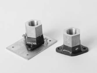
19 2.2.7 OTHER COMPONENTS COMPONENT MATERIAL AVAILABLE SIZES Appliance Stubouts Pipe: Schedule 40 Steel Plate: Steel NPS x Pipe Length: - 1 /2 NPS - 3 /4 NPS COMPONENT MATERIAL AVAILABLE SIZES NPS x Pipe Length: Meter Pipe: Schedule 40 Steel - 1 /2 x 6" Stubouts Plate: Steel - 1 /2 x 12" - 3 /4 x 6" - 3 /4 x 12" - 1 x 6" - 1 x 12" /4 x 6" /4 x 12" COMPONENT MATERIAL AVAILABLE SIZES Fireplace Stubout Pipe: Schedule 40 Steel Plate: Steel NPS x Pipe Length: - 1 /2 x 7" COMPONENT MATERIAL AVAILABLE SIZES Manifold Bracket Bracket: 16 Gauge Steel 16

 20M (3/4 ) COMPONENT MATERIAL")


20 2.2.7 OTHER COMPONENTS COMPONENT MATERIAL AVAILABLE SIZES Right Angle Mounting Bracket Bracket: Steel Fits CSST Adapter Nuts Sizes: - 3 /8" and 1 /2" - 3 /4" COMPONENT MATERIAL AVAILABLE SIZES Gas Outlet Box Box: Plastic Valve: Brass 15M (1/2 ) 20M (3/4 ) COMPONENT MATERIAL AVAILABLE SIZES Quick Connects Box: Plastic Valve: Brass Surface Mount Kit: - 1 /2 NPS Valve Only: - 1 /2 NPS COMPONENT MATERIAL AVAILABLE SIZES Bonding Clamp Clamp: Bronze 1.WFBC: - Fits 3 /8 through 1 ridged pipe sizes 2.WFBC: - Fits 1 1 /4 through 2 Ridged pipe sizes. UL 467 Approved 17
21 3.0 SYSTEM CONFIGURATION AND SIZING 3.1 SYSTEM OVERVIEW INTRODUCTION The following section will be used to assist you while you design and size your WARDFLEX /WARDFLEX II fuel gas piping system. At any point in which you require further assistance with this process you can visit our webpage ( or contact Ward Manufacturing s Engineering Department. WARDFLEX and WARDFLEX II are required to be tested, listed, and installed in accordance with the Standard For Fuel Gas Piping Systems Using Corrugated Stainless Steel Tubing, ANSI LC1. It is required by this standard to provide installation instructions which include proper sizing tables and methods of sizing SYSTEM DESIGN In order to properly design a fuel gas piping system you must first recognize all the important criteria. Requirements for a proper system design include: Verify your system meets all local codes. When local codes are in conflict with the manufactures guidelines the local codes must always take precedence. Determine the supply pressure coming from the meter by means of a gauge or a rating supplied by the gas company. Determine your total system demand for all appliances as well as the largest single load. Prepare a floor plan sketch with the load and length combinations for all appliances. Determine your allowable pressure drop. IMPORTANT NOTE: When choosing a pressure drop to size a WARDFLEX /WARDFLEX II system the minimum operating pressure of the appliance must be considered. Choosing a pressure drop that will reduce the supply pressure below the minimum operating pressure of the appliance will cause the appliance to perform poorly or not at all. Example: System Supply Pressure: 7 inches W.C. Appliance minimum operating pressure: 5 inches W.C. The use of a 3 inch W.C. pressure drop would result in a minimum inlet pressure at the appliance of 4 inches W.C. In this case an alternate pressure drop of 2 inches or less should be selected to meet the minimum operating pressure of the appliance. 3.2 SYSTEM CONFIGURATIONS INTRODUCTION There are multiple configurations in which you can install gas piping systems. The following sections will explain these different types of configurations. To the right is a key to accompany the figures used throughout the section: KEY: M BLACK PIPE WARDFLEX PIPE METER APPLIANCE SHUT OFF VALVE MANIFOLD REGULATOR TEE SERVICE SHUT OFF VALVE 18
22 3.2.2 SERIES SYSTEMS A series system is the most commonly used system for rigid pipe systems utilizing low pressure. A typical series system contains a main run (header) which branches off with tees to the individual appliances. An example of a series system can be seen in figure 3.1 LOW PRESSURE ( 1 2 PSIG) SERIES ARRANGEMENT TOTAL LOAD 215 CFH RANGE/OVEN 60 CFH WATER HEATER 40 CFH FURNACE 80 CFH M B D 1 2 PSIG AT METER A C E F DRYER 35 CFH FIGURE PARALLEL SYSTEMS In a parallel system a main run from the meter supplies a central distribution manifold. Individual runs from the manifold supply the appliances. Typically it is best to position the manifold closest to the appliance requiring the greatest load. An example of a parallel system can be seen below in figure 3.2. LOW PRESSURE ( 1 2 PSIG) PARALLEL ARRANGEMENT TOTAL LOAD 155 CFH FURNACE 80 CFH B M WATER HEATER 40 CFH 1 2 PSIG AT METER C A D DRYER 35 CFH FIGURE
23 3.2.4 DUAL PRESSURE SYSTEMS A dual pressure system utilizes two operating pressures downstream of the meter. The first pressure is set by the service regulator and is usually 2 PSI but can be higher or lower depending on local code. This is the high pressure side of the system. The second operating pressure also known as the low pressure side of the system is set with a pound-to-inches regulator. This pressure can be between 8 to 14 inches W.C. depending on local code, system design, and type of fuel gas. A dual pressure system is shown below in figure 3.3. HIGH PRESSURE (2 PSIG) PARALLEL ARRANGEMENT TOTAL LOAD 215 CFH RANGE/OVEN 60 CFH E FURNACE 80 CFH 2 PSIG AT METER M B C A D WATER HEATER 40 CFH DRYER 35 CFH FIGURE HYBRID SYSTEMS Hybrid systems incorporate the use of Corrugated Stainless Steel Tubing with rigid black pipe or copper tubing. In low pressure systems it is often advantageous to use CSST and rigid pipe in the same system. This will help reduce pressure drops in systems which contain long runs and/or high loads. WARDFLEX and WARDFLEX II are approved for use with any fuel gas piping system when approved pipe threads are used at the interface. A hybrid system is shown below in Figure 3.4. LOW PRESSURE ( 1 4 PSIG) HYBRID SYSTEM TOTAL LOAD 215 CFH 0.5 INCH W.C. DROP RANGE/OVEN 60 CFH E FURNACE 80 CFH B M C 1 4 PSIG AT METER A D WATER HEATER 40 CFH DRYER 35 CFH FIGURE
24 3.2.6 ELEVATED PRESSURE SYSTEM In an elevated pressure system a pounds-to-inches regulator is positioned directly in front of each appliance. This is typical in systems where there are long runs and/or high loads because it allows for the use of smaller tubing sizes while being able to supply the minimum inlet requirements of all appliances. An elevated Pressure system can be seen below in Figure 3.5. HIGH PRESSURE (2 PSIG) SERIES ARRANGEMENT TOTAL LOAD 600 CFH FURNACE 100 CFH FURNACE 100 CFH FURNACE 100 CFH M 2 PSIG AT METER FURNACE 100 CFH FURNACE 100 CFH FURNACE 100 CFH FIGURE SYSTEM SIZING INTRODUCTION This section will provide you with sizing methods and examples. The following procedures should be closely followed when sizing the WARDFLEX /WARDFLEX II system to ensure it will operate properly. Section 7 of this Design and Installation Guide contains tables that will help you properly select tubing sizes. Care should be taken to ensure you are using the correct tables for your system requirements. For additional assistance with sizing contact Ward Manufacturing s Engineering Department LONGEST LENGTH METHOD When using the longest length method to size a system you must use a table that fits your design criteria. For sizing each run of tubing you need to determine the total gas load for all appliances serviced by that section as well as the longest length that particular section delivers gas. The longest length must include the run from the meter to the furthest appliance. The longest length method can also be used for hybrid and dual pressure systems. In the case of a dual pressure system you would size the run from the meter to the regulator separately from the rest of the system. The following examples demonstrate the use of the longest length method. 21
25 EXAMPLE 1: LOW PRESSURE PARALLEL SYSTEM The following example demonstrates a typical single family house with 4 appliances with a centrally located manifold. The pressure at the meter is 14 inches W.C. (.5 PSI) and the allowable pressure drop is 6.0 inches W.C. Table A-9 will be used for this example. LOW PRESSURE LOAD ( 1 2 PSIG) PARALLEL ARRANGEMENT TOTAL LOAD 215 CFH RANGE/OVEN 60 CFH LENGTH OF RUN LOAD TUBE SIZE A=5 feet 215 CFH 15A (1/2 ) B=10 feet 80 CFH 10A (3/8 ) C=10 feet 40 CFH 10A (1/2 ) D=15 feet 35 CFH 10A (3/8 ) E=15 feet 60 CFH 10A (3/8 ) 1 2 PSIG AT METER M A 5 FEET E 15 FEET B 10 FEET C 10 FEET D 15 FEET FURNACE 80 CFH WATER HEATER 40 CFH DRYER 35 CFH FIGURE 3.6 SIZING PROCEDURE: 1. Size Section A Determine distance from meter to furthest appliance (range/oven 20 ft.). Determine total load supplied by A (215 CFH). Refer to Table A-9 for a length of 20 ft. and a load of 215 CFH. Section A will be size 15A tubing. 2. Size Section B Distance from meter to furnace is 15 ft. Load is 80 CFH. Table A-9 indicates size 10A tubing. 3. Size Section C Distance from meter to water heater is 15 ft. Load is 40 CFH. Table A-9 indicates size 10A tubing is required. 4. Size Section D Distance from the meter to the dryer is 20 ft. Load is 35 CFH. Table A-9 indicates size 10A tubing is required. 5. Size Section E Distance. From the meter to range/oven is 20 ft. Load is 60 CFH. Table A-9 indicates size 10A tubing is required. 22
26 EXAMPLE 2: LOW PRESSURE SERIES SYSTEM This example demonstrates a low pressure series arrangement. The main run (header) uses Tees to branch off to the appliances. The dryer has a separate service line to prevent the use of large tubing sizes. The pressure at the meter is 14 inches W.C. (.5PSI) and the allowable pressure drop is 6 inches W.C. Table A-9 will be used. LOW PRESSURE ( 1 2 PSIG) SERIES ARRANGEMENT TOTAL LOAD 215 CFH RANGE/OVEN 60 CFH WATER HEATER 40 CFH FURNACE 80 CFH LENGTH OF RUN LOAD TUBE SIZE A=10 feet 180 CFH 15A (1/2 ) B=15 feet 60 CFH 10A (3/8 ) C=10 feet 120 CFH 15A (1/2 ) D=5 feet 40 CFH 10A (3/8 ) E=10 feet 80 CFH 10A (3/8 ) F=10 feet 35 CFH 10A (3/8 ) 1 2 PSIG AT METER M F 10 FEET A 10 FEET B 15 FEET C 10 FEET DRYER 35 CFH D 5 FEET E 10 FEET SIZING PROCEDURE: FIGURE Size Section A Distance from meter to furthest appliance (furnace) is 30 ft. The load that A delivers is 180 CFH. Table A-9 at 30 ft. indicates a flow of 189 CFH with size 15A tubing. 2. Size Section B Distance from meter to range/oven is 25 ft. Load is 60 CFH. Table A-9 indicates size 10A tubing. 3. Size Section C The longest run from the meter that includes section C is 30 ft. (meter to furnace). The total load that C delivers is 120 CFH. Table A-9 indicates size 15A tubing. 4. Size Section D Meter to water heater is 25 ft. Load is 40 CFH. Table A-9 indicates size 10A tubing. 5. Size Section E The longest run that includes section E from the meter to the furnace is 30 ft. Load is 80 CFH. Table A-9 indicates size 10A tubing is required. 6. Size Section F The longest run that includes section F from the meter to the dryer is 10 ft. Load is 35 CFH. Table A-9 indicates size 10A tubing is required. 23
27 EXAMPLE 3: DUAL PRESSURE PARALLEL SYSTEM This example shows the proper way to size a dual pressure system. The use of two operating pressures downstream of the meter require two sizing tables be used and each side of the system should be sized separately. Tables A-6 and A-11 will be used. HIGH PRESSURE (2 PSIG) TOTAL LOAD 215 CFH RANGE/OVEN 60 CFH E 15 FEET FURNACE 80 CFH B 15 FEET LENGTH OF RUN LOAD TUBE SIZE 2 PSIG AT METER SUPPLY PRESSURE A=150 feet 215 CFH 20A (3/4 ) 2 PSIG B=15 feet 80 CFH 10A (3/8 ) 8 WC C=10 feet 40 CFH 10A (3/8 ) 8 WC D=25 feet 35 CFH 10A (3/8 ) 8 WC E=15 feet 60 CFH 10A (3/8 ) 8 WC M A 150 FEET C 10 FEET D 25 FEET DRYER 35 CFH WATER HEATER 40 CFH SIZING PROCEDURE: 1. Size Section A Determine distance from meter to regulator (150 ft.). Determine the load supply by A (215 CFH). Refer to Table A-11 to determine the tubing size needed to deliver the maximum system capacity at 2 PSIG use 20A per table A Size Section B Regulator to furnace is 15 ft. Load is 80 CFH. Table A-6 indicates size 10A tubing. 3. Size Section C Regulator to water heater is 10 ft. Load is 40 CFH. Table A-6 indicates size 10A tubing. 4. Size Section D Regulator to dryer is 25 ft. Load is 35 CFH. Table A-6 indicates size 10A tubing. 5. Size Section E Regulator to range/oven is 15 ft. Load is 60 CFH. Table A-6 indicates size 10A tubing. 24
28 EXAMPLE 4: HYBRID SYSTEM This example demonstrates a hybrid system which uses black pipe to the manifold and WARDFLEX CSST to the individual appliances. The supply pressure is 7 inches W.C. (.25 PSI) and the allowable pressure drop is.5 inches W.C. Table A-1 will be used for the CSST section and Table A-21 will be used for the black pipe section. LOW PRESSURE ( 1 4 PSIG) HYBRID SYSTEM TOTAL LOAD 215 CFH 0.5 INCH W.C. DROP RANGE/OVEN 60 CFH E FURNACE 80 CFH B M C LENGTH OF RUN LOAD TUBE SIZE 1 4 PSIG AT METER A=25 feet 215 CFH 1 SCHEDULE 40 B=15 feet 80 CFH 20A (3/4 ) C=10 feet 40 CFH 15A (3/4 ) D=15 feet 35 CFH 15A (1/2 ) E=15 feet 60 CFH 20A (3/4 ) A D DRYER 35 CFH WATER HEATER 40 CFH SIZING PROCEDURE: 1. Size Section A Distance from the meter to furthest appliance is 40 feet (dryer). Total load supplied by the section is 215 CFH. Using Table A-21 locate length of pipe at least 40 feet and a capacity of at least 215 CFH. You will find a capacity of 320 CFH which would indicate 1 Schedule 40 pipe. 2. Size Section B 40 ft. from the meter to the furnace and a load of 80 CFH. Refer to Table A-1 and locate a 40 ft. length at the left and follow across to capacity greater than or equal to 80 CFH. A capacity of 97 CFH is indicated with size 20A tubing. 3. Size Section C 35 ft. from the meter to the water heater and a load of 40 CFH. Table A-1 indicates size 15A tubing will be required. Capacity of 47 CFH is indicated with size 15A tubing. 4. Size Section D 40 ft. from the meter to the dryer and a load of 35 CFH. For a length of 40 ft., find a value greater than 40 CFH in Table A-1. A capacity of 47 CFH is indicated with size 15A tubing. 5. Size Section E 40 ft. from meter to the range and a load of 60 CFH. For a length of 40 ft. find a greater value than 60 CFH in Table A-1. The table indicates size 20A tubing. 25
29 3.3.3 SUMMATION SIZING METHOD An alternate solution to the longest length method is the summation sizing method which adds the pressure drops through a particular section of tubing or black pipe. This can be an useful method when the supply pressure and/or pressure drop is not indicated in one of the sizing charts. This method for sizing is more accurate than the longest length method because you re doing actual calculations for load and length combinations rather than taking from a range of values in a chart. Table A-23 through Table A-27 contain the pressure drop per foot values of WARDFLEX /WARDFLEX II as well as polyethylene and steel pipe. The procedure for the summation sizing method is as follows: 1. Make a sketch containing the load and lengths for your system. 2. Find the desired flow in the left hand column of Table A Now locate the desired tubing size in the top row of the table. The point at which these two intersect is your pressure drop per foot of the selected tubing size. 4. Multiply this value by the length of this portion of the system and you have pressure drop for this section of tubing. 5. Repeat this procedure for any additional legs in the system. 6. Now add up the pressure drops to find the total system pressure drop. 7. If this value is greater than the allowable pressure drop for the system you must increase your tubing or pipe size. The following example demonstrates the summation sizing method: EXAMPLE 5: LOW PRESSURE EXAMPLE This example demonstrates a single household with 3 appliances. The supply pressure is 5 inches W.C. with a.5 inch W.C. allowable pressure drop. TOTAL SUPPLY 150 CFH LOW PRESSURE (5" W.C.) 0.5 INCH W.C. DROP FIREPLACE 80,000 BTU 10 FEET WATER HEATER 40,000 BTU M 50 FEET 10 FEET 5 W.C. AT METER 60 FEET FIREPLACE 30,000 BTU LINE LENGTH (FEET) LOAD (CFH) TUBE SIZE Main CFH 32A (1 1/4 ) Furnace CFH 15A (1/2 ) Water Heater CFH 15A (1/2 ) Fireplace CFH 15A (1/2 ) 26
30 SIZING PROCEDURE: 1. Size the Main Line Pressure drop per foot for CFH is.002 Multiply that by the length of the section Pressure drop for this section is.100 (50 x.002) 2. Size the Furnace Line Pressure drop per foot for 80 CFH is.0353 Multiply that by the length of the section Pressure drop for this section is.353 (10 x.0353) 3. Size the Water Heater Line Pressure drop per foot for 40 CFH is.0087 Multiply that by the length of the section Pressure drop for this section is.087 (10 x.0087) 4. Size the Fireplace Line Pressure drop per foot for CFH is.0049 Multiply that by the length of the section Pressure drop for this section is.294 (60 x.0049) 5. Add the Main line pressure drop to the pressure drop of the individual appliance lines Pressure drop at Furnace =.453 ( ) Pressure drop at Water Heater =.187 ( ) Pressure drop at Fireplace =.394 ( ) 6. Check all the pressure drops to be sure they are at or below the allowable pressure drop. All pressure drops in this example were below the allowable.5 inch W.C. pressure drop therefore the current tubing sizes will work for this application. If a particular appliance run had a pressure drop larger than.5 inches of W.C. you would need to repeat the process with a larger tubing size. Also, if you would like to maintain smaller tubing sizes you can repeat the calculations for smaller tubing until you exceed the allowable pressure drop WARDFLEX SIZING SOFTWARE Ward Manufacturing the makers of WARDFLEX CSST have provided free sizing software that is available as a free download on the WARDFLEX webpage at The software can be downloaded onto a personal computer and used to size WARDFLEX and WARDFLEX II fuel gas systems as well as hybrid systems. The sizing utilizes the summation sizing method to help you achieve smaller tubing sizes. Some features of the software include: Ability to size low pressure, dual pressure, and hybrid systems. Choose between Natural gas and propane. Size add-ons to systems by drawing out the existing arrangement. Choose between English or metric units. Select 1 of 3 methods for supply parameters. 27

31 4.0 INSTALLATION PRACTICES 4.1 GENERAL INSTALLATION PRACTICES ATTENTION: WARDFLEX AND WARDFLEX II ARE ENGINEERED FUEL GAS PIPING SYSTEMS AND AS SUCH, THE TUBING AND FITTINGS ARE NOT INTERCHANGEABLE WITH OTHER CSST MANUFACTURES PRODUCT. THE USE OF OTHER CSST PRODUCTS WITH BOTH WARDFLEX AND WARDFLEX II IS PROHIBITED. CONNECTION BETWEEN TWO DIFFERENT MANUFACTURERS CSST PRODUCTS MAY BE ACCOMPLISHED USING MALLEABLE IRON PIPE FITTINGS WITH ASME B COMPLIANT THREADS. A. All System hardware should be stored in its original package in a clean dry location prior to installation. Care must be taken to ensure WARDFLEX AND WARDFLEX II CSST is not damaged prior to installation. B. Tubing ends must be temporarily capped, plugged or taped proir to installation to prevent dirt or other foreign debris from entering the tubing. C. Tubing exposed to extreme low temperatures should be allowed to come up to room temperature prior to installation. D. Care must be taken to not kink, tangle, twist, stretch or apply excessive force to the tubing or fittings. WARDFLEX AND WARDFLEX II are flexible piping system and can be bent during installation around obstructions. Avoid stressing the tubing with tight bends and repetitive bending. Refer to Table 4.1 for recommended bend radius for both WARDFLEX AND WARDFLEX II. TUBING SIZE ABSOLUTE MINIMUM BEND RADIUS RECOMMENDED INSTALLED BEND RADIUS INCHES 10A (3/8") 3/4" 3" 15A/15C (1/2") 3/4" 3" 20A/20C (3/4") 1" 3" 25A/25C (1") 1-1/4" 3" 32A/32C (1-1/4") 1-5/8" 4" 38A/38C (1-1/2") 4" 5" 50A/50C (2") 4-1/2" 6" Table 4.1 E. When installing in, through or around sharp metal structures (i.e. metal studs, sheet metal, i-beams), rubber grommets or protective tubing should be used to prevent any direct contact which could subject the tubing to damage. 28
32 F. Tubing should be supported in a workman like manner with metallic pipe straps, bands, brackets, hangers or building structural components suitable for the size of piping support intervals are not to exceed those shown in Table 4.3. A proper support is one which is designed to be used as a pipe hanger, does not damage the tubing during installation, and provides full support of the tubing once installed. Plastic zip ties and/or cable ties are not to be used as the primary support for the CSST tubing. ATTENTION: WHEN SUPPORTING WARDFLEX YELLOW JACKETED CSST AVOID USING CONDUCTIVE METALLIC SYSTEMS SUCH AS, DUCTING, PIPING, VENTING, AND ELECTRICAL CABLES TO SUPPORT THE PIPING. G. WARDFLEX /WARDFLEX II system components shall not be exposed to any acids, bases, salts or other caustic materials. Some chemical compounds have been identified that may aggressively corrode 304 stainless steel. Contact with these chemicals should be absolutely avoided. Any contact should immediately and thoroughly be washed off. The plastic covering is not affected by these compounds and will protect the tubing as long as it is undamaged. Should the plastic covering become damaged, wrapping 2 layers of WARDFLEX self fusing tape around the exposed area will help prevent from exposure to the caustic materials. See the list below of some chemicals to avoid. CHEMICALS TO AVOID INCLUDE: BUT NOT LIMITED TO: Hydrochloric Acid (common name: muriatic or brick wash) Zinc Chloride and Ammonium Chloride (soldering flux, pool algaecide) Calcium or Sodium Hypochlorite (bleach or pool chemicals) Copper Chloride (may be found in fungicides or wood preservatives) Ferric Chloride (swimming pool flocculent) Phosphoric Acid (scale removers) Sodium Chloride (salt water) Sulfuric Acid (battery acid) Leak detection with chloride-containing compounds found in some common soap (e.g., dishwashing soap) can corrode WARDFLEX. Avoid use of these compounds in connection with WARDFLEX. ANY LEAK DETECTION SOLUTION COMING IN CONTACT WITH THE WARDFLEX SYSTEM SHOULD HAVE A SULFUR AND HALOGEN CONTENT OF LESS THAN 10 PPM OF EACH (ASTM E section 7.4). 29


33 4.2 FITTING ASSEMBLY WARDFLEX AND WARDFLEX II STEPSAVER FITTING Step 1 - Cut the Tubing Using a tubing cutter, cut the WARDFLEX or WARDFLEX II tubing to the desired length. Then using a utility knife remove the coating to expose a minimum of four corrugations. NOTE: The coating on the WARDFLEX II tubing shall be stripped back no more than 5 corrugations. Be sure not to score the tubing while removing the plastic coating. Step 2 - Install the Nut and Retainer Slide the nut over the tubing and place the retainer ring. Leave one corrugation exposed from the end of the retainer to the end of tubing. The small end of the retainer must point towards the cut end of the tubing. Step 3 - Install the Body Slide the nut over the retainer and thread it onto the body rotating only the nut. Step 4 - Wrench Tighten Using appropriate wrenches tighten the nut until it fully contacts the body. Tightening torque should not exceed the maximum torque listed in Table 4.2 Do not use any thread sealant on the CSST Connection. Thread sealant should be used only for NPT threaded connections. NOTE: DURING TIGHTENING, ROTATE THE NUT ONLY; THE BODY MUST NOT BE ROTATED WITH RESPECT TO THE TUBING. TUBING SIZE WARDFLEX MAXIMUM TIGHTENING TORQUE 10A (3/8") 50 ft-lb 15A (1/2") 50 ft-lb 20A (3/4") 120 ft-lb 25A (1") 160 ft-lb 32A (1-1/4") 200 ft-lb 38A (1-1/2") 200 ft-lb 50A (2") 200 ft-lb Table
34 4.2.2 WARDFLEX / WARDFLEX II FITTING REASSEMBLY A. The STEPSAVER fitting, with its patented dual seal technology which when installed correctly, will give you a quick reliable seal the first time every time. Should the need arise to disassemble a WARDFLEX STEPSAVER fitting,it may be reused if: The metal to metal and gasket seals show no signs of extensive physical damage. The threads on both the nut and body of fitting assembly show no signs of extensive physical damage. Both halves of the retainer are intact. B. The WARDFLEX /WARDFLEX II 38M (1 1/2 ) and 50M (2 ) fittings are also allowed for reuse if: The gasket seals show no signs of extensive physical damage. If the gasket is damaged, replacements are available. The threads on both the nut and body of fitting assembly show no signs of extensive physical damage. Both halves of the retainer are intact. C. As with any installation, a pressure test should always be performed before placing the piping system into service. See section 6.1 for Pressure Testing and Inspection Procedure 31
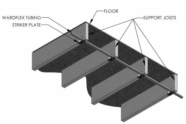
35 4.3 TUBING ROUTING VERTICAL RUNS Vertical runs inside hollow wall cavities are the preferred location for installation of vertical sections. To avoid damage, tubing should be free to move within the wall cavity without immediate supports between floors but must be supported at the point of penetration between floors. Vertical run support spacing is not to exceed 10 feet, requiring hangers only where the height of each floor is greater than 10 feet. The run must conform to Section 4.4 Protection, if it is installed in a location that it will be concealed HORIZONTAL RUNS Areas beneath, alongside, or through floor and ceiling joists or other structural members are typical installation locations for both residential and commercial applications. Structural members may be considered supports for horizontal tubing if they meet the requirements as specified in Table 4.3. The run must conform to Section 4.4 Protection, if it is installed in a location that it will be concealed. ATTENTION: CARE SHOULD BE TAKEN WHEN INSTALLING WARDFLEX YELLOW JACKETED CSST, TO MAINTAIN AS MUCH SEPARATION AS REASONABLY POSSIBLE FROM OTHER ELECTRICALLY CONDUCTIVE SYSTEMS IN THE BUILDING. TUBING SIZE MINIMUM SUPPORT INTERVAL 10A (3/8 ) 4 feet. 15A/15C (1/2 ) 6 feet. 20A/20C (3/4 ) 8 feet USA 6 Feet Canada 25A/25C (1 ) 8 feet USA 6 Feet Canada 32A/32C (1-1/4 ) 8 feet USA 6 Feet Canada 38A/38C (1-1/2 ) 8 feet USA 6 Feet Canada 50A/50C (2 ) 8 feet USA 6 Feet Canada Table CLEARANCE HOLES AND NOTCHING Clearance holes for routing WARDFLEX / WARDFLEX II CSST shall have a diameter at least ½ greater than the outside diameter of the tubing. The minimum hole diameters for each tubing size are listed in Table 4.4. Table 4.5 identifies some basic guidelines if drilling and/or notching is required of any structural member. However you should always check local code requirements before proceeding. A. Holes drilled in vertical members of the wall framing should not exceed 1/4 the width of the member. B. Holes drilled in plates and other horizontal frame members should not exceed 1/2 the width of the member. C. Where a hole is to be drilled in a joist, the outside edge of the hole should be located not less than 3 in. away from the floor or ceiling. D. Notching is not preferred practice, however, when notching, the notched depth must be a minimum of one tubing diameter with the maximum notch being determined by local code. E. See Table 4.5 for typical maximum hole sizes in structural members. Table 4.4 TUBING SIZE MINIMUM CLEARANCE HOLE DIAMETER 10A (3/8 ) 15A/15C (1/2 ) 20A/20C (3/4 ) 25A/25C (1 ) 32A/32C (1-1/4 ) 38A/38C (1-1/2 ) 50A/50C (2 ) 1-1/8" 1-1/4" 1-1/2" 1-3/4" 2-1/4" 2-5/8" 3-1/4" 32
 25A/25C (1 ) 25A/25C (1 ) 25A/25C (1 ) 25A/25C (1 ) 32A/32C (1-1/4 ) 4.3.4 CONCEALED LOCATIONS FOR FITTINGS WARDFLEX /WARDFLEX II mechanical fittings have been tested and listed per the requirements of ANSI LC-1 /CSA 6.")

36 A B C D E F DESCRIPTION 2"x4" Stud Load Bearing Wall 2"x4" Stud Non- Load Bearing Wall 2"x4" Sole Plate 2"x4" Top Plate 2"x6" Floor Joist 2"x8" Floor Joist MAX. HOLE SIZE Maximum WARDFLEX Tubing Size Table A/20C (3/4 ) 25A/25C (1 ) 25A/25C (1 ) 25A/25C (1 ) 25A/25C (1 ) 32A/32C (1-1/4 ) CONCEALED LOCATIONS FOR FITTINGS WARDFLEX /WARDFLEX II mechanical fittings have been tested and listed per the requirements of ANSI LC-1 /CSA This specification provides test requirements which certify fittings for concealed locations and connections where accessibility is not possible. When the use of a concealed fitting is required always reference the National Fuel Gas Code NFPA 54 or CSA B149 or other relevant local code. These guidelines address some of the known situations which may require the use of concealed fittings. This guide cannot address all applications of concealed fittings but provides instead typical instructions to demonstrate the principles which apply to fittings listed for installation in concealed locations. Figure 4.3 Multiple gas outlets connected to the same run of WARDFLEX / WARDFLEX II. In this situation a tee-type fitting can be used and installed in a concealed location. Figure 4.3 Figure 4.4 Appliance stub out with a WARDFLEX / WARDFLEX II female mechanical fitting which can be installed in a concealed location. For this type of arrangement refer to section 4.4 on for protection details. Figure
37 Installation in or through chimneys, clothes chutes, gas vents, dumbwaiters, and elevator shafts are all prohibited locations for A. WARDFLEX /WARDFLEX II fittings and tubing. B. Manifold stations for dual pressure systems, which include the multiport manifold, shutoff valves, and/or pressure regulators, shall not be installed in concealed locations regardless of the qualifications of the tubing fittings. C. Fittings installed inside accessible enclosure boxes, for such items as quick connect gas outlets or fire place shut off valves, are exempted from these guidelines MODIFICATION TO EXISITNG SYSTEM A. New Ceilings in Unfinished Rooms/Basements - CSST fittings originally installed in accessible ceiling locations can be concealed in the event a ceiling is installed at a later date. B. Extension to Existing Tubing Run - Concealed CSST can be modified to permit an extension to another appliance location provided there is sufficient capacity to supply both applications at the same time. If an accessible location for the modification is not available, the existing tubing run can be modified with a tee fitting, resulting in a concealed fitting. C. When any modification to an existing CSST installation leads to concealed tubing, protection devices may be required. Refer to Section 4.4 for details on protection OUTDOOR INSTALLATIONS Per ANSI LC-1/CSA 6.26 WARDFLEX /WARDFLEX II CSST products are approved for installation where exposure to outdoor environments can occur. The following guidelines shall be followed when installing WARDFLEX /WARDFLEX II outdoors to protect tubing and fittings from the effects of weather. A. The covering shall remain intact as much as practical for the given installation. Any portion of exposed stainless steel shall be wrapped with tape (e.g. PVC, Self Fusing Silicone) or sleeved (e.g. PVC, Polyolefin) to prevent corrosive attack by acid wash or other caustic compounds that may be present. If contact with caustic compounds should occur ensure that all traces are immediately removed to prevent premature corrosion failure. B. WARDFLEX /WARDFLEX II mechanical joint fittings shall be protected from the effects of weather when used outdoors. After the connection is made to outdoor equipment the fitting assembly shall be wrapped with tape (e.g. PVC, Self Fusing Silicone) or by applying shrink sleeves (e.g. PVC, Polyolefin) around the entire assembly. C. When installed outdoors between grade and six feet above WARDFLEX /WARDFLEX II must be protected inside non-metallic conduit or installed in a location where it will not be subjected to mechanical damage. D. When installed in crawl spaces or underneath mobile homes, WARDFLEX /WARDFLEX II shall be installed in accordance with these installation instructions FIRE RATED CONSTRUCTION A. WARDFLEX /WARDFLEX II have been reviewed for installation through UL Classified fire rated construction and is listed for use in a number of UL Through Penetration Firestop System Listings. See table 4.6 for a complete listing. System numbers are subject to change and deletion be sure to verify systems in the latest revision of UL Fire Resistance. In the event there is a conflict between this guide and UL, UL takes precedence. 34

38 SYSTEM No. W-L-1182 WALLBOARD TYPICAL INSTALLATIONS SYSTEM No. F-C-1062 WALL OR FLOOR FIRECAULK SYSTEM No. C-AJ-1329 FIRECAULK FIRECAULK JOIST OR STUD WARDFLEX WARDFLEX WALL OR CEILING WARDFLEX CONCRETE WALL / FLOOR R18357 WARDFLEX UL Through Penetrating Firestop Listings System No. Rating hr F T Firecaulk Product Remove Covering Max Size Max Quantity C-AJ & C-AJ R 2 1 C-AJ & C-AJ & /4 1 C-AJ & /4 1 C-AJ /4 3 C-AJ /4 3 C-AJ C-AJ C-AJ >1 C-AJ C-AJ C-AJ >1 C-AJ OR MORE C-AJ , 7, 10, 1 1 C-AJ & C-AJ , 10, 13, OR MORE C-AJ /4 1 OR MORE C-AJ & F-C & R 2 1 F-C /4 & 1 1/4 & /2 1 F-C /4 & 1 1/4 & /2 1 F-C & 2 1/4, 1/2 & F-C & 2 1/4, 1/2 & >1 F-C / F-C / F-E F-E >1 F-E / F-E / W-J /4 1 W-J /4 1 W-J /4 3 W-J /4 3 W-J /4 1 W-J W-J >1 W-J /4 7 1 >1 W-J / W-J & 2 3/4 & 1 1/ /4 1 OR MORE W-L-1001 VARIES VARIES W-L R 2 1 W-L & 2 1 & /4 1 W-L & 2 1 & /4 1 W-L & 2 1 & /4 3 W-L & 2 1 & /4 3 W-L & 2 1 & /4 1 W-L & 2 1 & /4 1 W-L /4, 3/4 & /4 1 W-L W-L >1 W-L & W-L & 2 0 & 1/4 7 1 >1 W-L & 2 0 & 1/ W-L & W-L & 2 3/4 & 1 1/ /4 1 OR MORE W-L & 2 3/4 & 1 1/ /4 1 W-L & OR MORE System No. explanations: First alpha: F=floor is being penetrated, W=wall, C=walls or floors, E=Floor-ceiling assemblies consisting of concrete with membrane protection Second alpha: A=concrete floors with a minimum thickness less than or equal to 5 inches, C= framed floors,j=concrete or masonry walls with a minimum thickness less than or equal to 5 inches, L= framed walls. Rating hours: F= flame passage criteria, T= temperature rise of 325 F. Firecaulk Products: 1 3M COMPANY: CP-25-WB+, 2 Rectorseal: Metacaulk 1000, 3 Rectorseal: Biostop 500+ caulk, 4 Specified Technology: SpecSeal LCI sealant, 5 Specified Technology: SpecSeal 100, 101, 102, 105, 120 or 129, 6 Specified Technology: SpecSeal 100, 101, 105, 120 or 129 Sealant, SpecSeal LC 150, 151, 152or 155 Sealant may be used for 2 hr F Rating only. 7 3M COMPANY: IC 15WB, 8 EGS NELSON FIRESTOP: LBS+, 9 HILTI INC: FS-ONE Sealant 11 Rectorseal: Biostop 350i 12 NUCO INC: Self Seal GG M COMPANY: FB 1000 NS 14 3M COMPANY: FB 1003SL IC 15WB+ 15 Hercules Chemical: Hercules Plumbers Firestop Sealant 16 Rectorseal: Metacaulk 350i 17 HILTI INC: CP NUCO CO Self Seal GG Rectorseal FlameSafe FS900+ or FS1900 Consult UL Fire Resistance Directory-Volume 2 for specific construction details or contact WARD MANUFACTURING These can be downloaded directly from UL s web site: 35

39 4.4 PROTECTION INTRODUCTION WARDFLEX /WARDFLEX II tubing shall be protected from physical damage caused by screws, nails, drill bits, etc. The tubing is most susceptible to puncture at all points of support. The best practice is to install the tubing in those areas where the likelihood of physical damage is minimized and no protection is needed; for example: A. Where tubing is supported at least 3 inches from any outside edge of a stud, joist, etc. or wall surface. B. Where any unsupported tubing can be displaced in the direction of potential penetration at least 3 inches. C. Where tubing is supported under the joist in basements or crawl spaces and is not concealed by wall board or ceilings. When WARDFLEX /WARDFLEX II is installed in locations where the potential of physical damage exists, the use of hardened steel striker plates, listed for use with CSST, must be used. Striker plates other than those provided for use with WARDFLEX /WARDFLEX II are prohibited. The tubing may also be routed inside strip wound conduit or schedule 40 pipe when protection is required. In areas where penetration through studs, joists, plates and other similar structural members occur striker protection is required when all of the following criteria apply: 1. When the piping system is installed in a concealed location and is not viewable. 2. When the piping system is installed in a location that does not allow free movement to avoid puncture threats. 3. When the piping system is installed within 3 inches of possible points of penetration. DOUBLE TOP STRIKER PLATE FULL STRIKER PLATE FIRE RATED GAS OUTLET BOX HALF STRIKER PLATE APPLIANCE STUBOUT LONG STRIKER PLATE STRIPWOUND CONDUIT Figure STRIKER PLATES Striker plates are used to prevent tubing damage in areas where potential penetration threats exist through studs, joists, plates, and other similar structural members. Only striker plates supplied by Ward Manufacturing are permitted for use with WARDFLEX /WARDFLEX II. For installations where all three above criteria apply the following striker plate protection must be applied. 36
40 A. At concealed support points and points of penetration less than 2 inches from any edge of a stud, joist, plate, etc. shielding is required at the area of support and extending 5 inches in one or both directions (if appropriate). B. At concealed support points and points of penetration within 2 to 3 inches from any stud, joist, plate, etc., listed quarter striker plates are required at the area of support. Figure 4.7 and Figure 4.8 show proper means of protection for this type of installation. Figure 4.6 Typical locations where striker plates are required. Striker plates are installed at both horizontal penetrations unrestrained vertical runs of 26 inches or greater require no additional protection. LESS THAN 2 GREATER THAN 3 Figure 4.6 STRIPWOUND METAL CONDUIT Figure 4.7 Figure 4.8 C. Tubing routed horizontally through structural members shall be protected from puncture threats with the appropriate shielding material. At penetration joints, listed striker plates of the appropriate size shall be utilized. Tubing between constraints that are less than 24 inches apart and meeting the criteria requiring full striker plates, shall be additionally protected by stripwound metal-conduit, or schedule 40 pipe. D. CSST greater than 1 nominal diameter installed within a concealed hollow wall cavity of 2 x 4 construction shall be protected along the entire concealed run length with stripwound metal conduit, or schedule 40 pipe. E. Should an unfinished ceiling (I.e. basement) be covered at a later date, the quarter striker plates, shown in figure 4.9 and 4.10, should be replaced with appropriate protection devices that provide adequate protection for potential penetration threats. F. Although figures 4.9 and 4.10 are acceptable, installation method 4.11 is preferred. 37

41 Figure 4.9 Figure 4.10 Figure


42 4.4.3 STRIPWOUND METAL CONDUIT A. At termination points not covered by ANSI specifications, standard stripwound metal conduit shall be installed as additional protection. Stripwound conduit shall not be used as a substitute for striker plates where tubing passes through structural members. B. Stripwound conduit shall also be used to shield tubing from puncture threats when WARDFLEX /WARDFLEX II is installed in a concealed location where it cannot be displaced a minimum 3 from a potential puncture threat or the distance between supports is less than 24 inches. See Figure Figure 4.12 Figure 4.13 Figure 4.13 Termination fitting for an appliance connection with stripwound conduit providing extra protection inside the wall and floor cavities. 39
43 4.4.4 INSTALLATION IN INSULATED WALLS Rigid installations present significant puncture threats for WARDFLEX / WARDFLEX II installations in concealed spaces. In concealed spaces, e.g. wall cavities, rigid insulation will prevent CSST from being displaced. WARDFLEX /WARDFLEX II shall not be installed in a wall cavity with foam insulation without additional protection as described below. A. Tubing shall be routed through an approved conduit in walls where foamed in insulation is to be used i.e. rigid steel pipe or conduit. Approved conduit shall be secured according to local building practice. B. Protection methods such as pipe, conduit and strip wound hose, supply protection and give the tubing space in which to move. On exterior walls the tubing may be fastened to the sheathing with cable clamps or secured with sticks/wires sprung between studs to center tubing between interior and exterior surfaces. C. When tubing is installed inside walls with batt insulation the tubing shall be routed between the face (craft paper/vapor barrier) and the wall surface. If installed in a concealed location where it cannot be displaced a minimum 3 from a potential puncture threat the run shall be protected with stripwound conduit. D. CSST tubing does not need additional protection where it is more than three inches from any puncture threats although consideration must be given to the chance that it may migrate toward penetration threats as the insulation is applied and during curing. 40
44 4.5 METER-CONNECTIONS UNSUPPORTED METERS A. Meters which depend on the service and house piping for support shall not be directly connected to the flexible gas piping. B. The use of an outdoor termination fitting mounted to the exterior of the structure, meter stubout or other rigidly mounted termination fitting are acceptable transitional methods. METER CONNECTION -PIPE SUPPORTED METER NOTE: DIAMETER OF HOLE SHALL BE AT LEAST 1/2 GREATER THAN O.D. OF TUBING AND SHALL BE SLEEVED IN ACCORDANCE WITH LOCAL BUILDING CODE (IF APPLICABLE) SLEEVE (IF REQUIRED) HOUSE SERVICE REGULATOR SEALANT (TYPICAL) CSST TERMINATION FITTING METER SERVICE LINE Figure
45 METER CONNECTION - PIPE SUPPORTED METER NOTE: DIAMETER OF HOLE SHALL BE AT LEAST 1/2 GREATER THAN O.D. OF TUBING AND SHALL BE SLEEVED IN ACCORDANCE WITH LOCAL BUILDING CODE (IF APPLICABLE) Figure SELF SUPPORTED METER A. Meters which are independently supported by a bracket may be directly connected to WARDFLEX / WARDFLEX II. B. If practical a 3 to 6 in. loop of tubing should be included to compensate for meter movement and differential setting. NOTE: WARD MANUFACTURING DOES NOT REQUIRE MECHANICAL PROTECTION FOR OUTDOOR METER CONNECTION MORE THAN 6 FT. ABOVE GRADE HOWEVER, LOCAL CODES MUST BE CONSIDERED. CHECK WITH YOUR LOCAL CODE AUTHORITY. RADIUS OF 3 TO 6 INCHES SEALING NOTE: WHEN DIRECT CONNECTION OF WARDFLEX TO A METER IS BETWEEN 0 AND 6 FEET ABOVE GRADE THE TUBING MUST BE PROTECTED BY NON METALLIC PIPE (E.G. PVC). NOTE: DIAMETER OF HOLE SHALL BE AT LEAST 1/2 GREATER THAN O.D. OF TUBING AND SHALL BE SLEEVED IN ACCORDANCE WITH LOCAL BUILDING CODE (IF APPLICABLE) RADIUS OF 3 TO 6 INCHES SEALING SEALING Figure 4.17 NO RADIUS REQUIRED FOR STRAIGHT RUN 42

46 4.6 APPLIANCE CONNECTIONS MOVEABLE APPLIANCES IMPORTANT WARDFLEX /WARDFLEX II ARE NOT RATED AS FLEXIBLE APPLIANCE CONNECTORS AND MUST NOT BE DIRECTLY CONNECTED TO MOVABLE APPLIANCES. A. When using WARDFLEX or WARDFLEX II with moveable appliances such as a ranges or dryers, the tubing must be rigidly terminated before the appliance. Appliance stub outs, termination fittings or transitioning to rigid black pipe are acceptable means to terminate CSST prior to the appliance. B. Final connection from CSST termination point to a movable appliance shall be made with a flexible appliance connector or another approved connection device. Figure 4.18 Figure 4.19 Figure
47 4.6.2 NON-MOVEABLE APPLIANCE A. WARDFLEX /WARDFLEX II can be directly connected to a non-moveable appliance such as a furnace or water heater (Figure 4.21) (be sure to check with local code if this is acceptable prior to installation). B. In this type of application, no termination fitting is required and the CSST should be terminated at the appliance shut off valve. ATTENTION: WHEN NON-MOVABLE APPLIANCES UTILIZE METALLIC VENTS WHICH EXTEND BEYOND OR PROTRUDE THROUGH THE ROOF, CONTACT BETWEEN WARDFLEX YELLOW COATED CSST AND THE APPLIANCE CABINET OR VENT IS PROHIBITED. Figure OUTDOOR APPLICANCES-BARBEQUE GRILL AND GAS LIGHT CONNECTION A. Movable grills shall be connected using an approved outdoor appliance connector which shall be attached to the CSST system at either a termination fitting, quick disconnect or other rigidly mounted transition fitting (Figure 4.22). An approved outdoor appliance connector shall be used to connect the appliance to the gas piping system. B. Permanently mounted grills located on decks shall be connected to the CSST system as shown in figure 4.23 and in accordance with the manufacturer s instructions. The outdoor portion of the CSST system shall be supported against the side of any inside deck joist. C. Permanently mounted outdoor lights located on decks shall be connected to the CSST system in the manner as permanently mounted grills as shown in figure 4.23 and in accordance with manufacturer s instructions. D. Yard mounted lights shall be connected to the CSST system as shown in figure All WARDFLEX /WARDFLEX II installed below grade shall be routed through nonmetallic watertight conduit and fittings protected in accordance with the requirements of section Outdoor Installation. STURGIS MODEL 3/375 BBQ QUICK - CONNECT OUTLET INSIDE WALL ENCLOSURE BOX* ELEVATED DECK- A FIXED PEDESTAL MOUNT GRILL OR GAS LIGHT - DIRECT CONNECTION NOTE: DIAMETER OF HOLE SHALL BE AT LEAST 1/2 GREATER THAN O.D. OF TUBING AND SHALL BE SLEEVED IN ACCORDANCE WITH LOCAL BUILDING CODE (IF APPLICABLE) MODEL 3/375 QUICK CONNECT OUTLET OUTSIDE WALL GROMMET SECTIONAL VIEW CONNECTION OF CSST TO GRILL CONTROLS/SHUT OFF VALVE SHALL BE IN ACCORDANCE WITH THE MANUFACTURER S INSTRUCTIONS STRIKER PLATES STRIPWOUND METAL HOSE OUTDOOR WOODEN DECK *SEE MANUFACTURER S INSTRUCTIONS FOR ENCLO- SURE MOUNTING AND QUICK CONNECT INSTALLATION Figure 4.22 SUB- FLOOR FLOOR JOIST Figure 4.23 HOUSE FOUNDATION NOTE: CSST SHALL BE INSTALLED ONLY ON INSIDE SURFACES OF JOISTS AT THE CENTERLINE 44
48 GROUND LEVEL GAS LIGHT/PEDESTAL BBQ GRILL - BURIED CONNECTION BBQ GRILL PEDESTAL OR GAS LAMP POST OUTDOOR TERMINATION FITTING 90 ELBOW MANUAL SHUT OFF VALVE SMALL GAP BETWEEN CONDUIT AND FITTING IS PERMITTED SEAL AGAINST WATER ENTRY PROTECTION REQUIRED UP TO 6 FT. ABOVE GROUND CONNECTION OF CSST TO GRILL CONTROLS/SHUT OFF VALVE SHALL BE IN ACCOR- DANCE WITH THE MANUFAC- TURER S INSTRUCTIONS PLASTIC CONDUIT ABOVE AND BELOW GROUND MINIMUM BURIAL DEPTH 12 OR IN COMPLIANCE WITH LOCAL CODE Figure SPECIAL APPLICATIONS A. Roof Top Installations For a roof top appliance no additional mechanical protection of the tubing is required. Whenever possible, roof penetrations shall include an outdoor termination fitting and shall be located within 6 feet of the equipment to be connected as shown in figure All long runs of tubing shall be supported in accordance with minimum support intervals in Table 4.3 and raised above the roof distance determined by local code/practice. WARDFLEX /WARDFLEX II routed vertically up the side of a building, to the roof, shall be protected in accordance with section Outdoor Installation. LONG OUTDOOR CONNECTION TO ROOF MOUNTED EQUIPMENT TYPICAL NON-METALLIC TUBING SUPPORT EVERY 4 FT. TUBING ELEVATED* INCHES ABOVE ROOF STANDARD ROOF PENETRATION SHUT OFF VALVE 4 FT. TYP UNION GAS APPLIANCE** WATER PROOFING TUBING CLIP CSST CONCRETE SLAB HUNG CEILING Figure 4.25 * HEIGHT OF ELEVATION BASED ON LOCAL PLUMBING/BUILDING CODE REQUIREMENTS AND/OR WINTER ICE BUILDUP. ** WHEN THE EQUIPMENT MANUFACTURER REQUIRES THE USE OF A FLEXIBLE CONNECTOR. 45
49 SHORT (1 TO 6 FT.) OUTDOOR CONNECTION TO ROOF MOUNTED EQUIPMENT SHUT OFF VALVE UP TO 6 FT. RIGID PIPE GAS APPLIANCE* STANDARD ROOF PENETRATION UNION WATER PROOFING CONCRETE SLAB Figure 4.26 TUBING CLIP CSST HUNG CEILING *WHEN THE EQUIPMENT MANUFACTURER REQUIRES THE USE OF A FLEXIBLE CONNECTOR B. Infrared Heaters Infrared heaters mounted from ceilings and walls of structures shall be connected to WARDFLEX /WARDFLEX II system as shown in figure 4.27 and installed in accordance with manufacturer s instructions and ANSI Standard for gas fired infrared heaters. CEILING JOIST ELEVATION VIEW GAS CONTROLS ROOF ATTIC SPACE GAS CONTROLS HANGING RODS HEATER SHUT OFF VALVE GAS CONTROLS STANDARD ELBOW HEATER MOUNTING BRACKET SECTIONAL VIEW WALL STUD EXTERIOR Figure 4.27 A) CEILING MOUNT (PROTECTED AREA) B) WALL MOUNT (PROTECTED AREA) C) WALL MOUNTED OUTDOORS 46
50 C. Pad Mounted Gas Appliances Gas appliances mounted on concrete pads or blocks, such as heat pumps, air conditioners, pool heaters and NGV refueling systems, shall be connected to the WARDFLEX /WARDFLEX II system at a termination fitting using either rigid pipe or an approved outdoor appliance connector as shown in Figure Pad mounted equipment (in most cases) is considered fixed if not moved for cleaning, maintenance, etc. (i.e. A/C units). PAD MOUNTED GAS APPLIANCES STEEL PIPE OR APPROVED OUT- DOOR APPLIANCE CONNECTOR CSST TERMINATION FITTING SHUT OFF VALVE CSST APPLIANCE NOTE: DIAMETER OF HOLE SHALL BE AT LEAST 1/2 GREATER THAN O.D. OF TUBING AND SHALL BE SLEEVED IN ACCORDANCE WITH LOCAL BUILDING CODE (IF APPLICABLE) PAD MOUNTED GAS APPLIANCE -AIR CONDITIONER -POOL HEATER -NGV REFUELING -OTHER CAP DRIP LEG (If required) CONCRETE PAD FOUNDATION WALL Figure


51 4.6.5 GAS FIREPLACES WARDFLEX /WARDFLEX II CSST shall not be routed directly into a metallic fireplace enclosure. The CSST connection shall be made outside of the enclosure to a section of rigid metallic pipe. A. When routing WARDFLEX and WARDFLEX II through masonry construction, for connection to gas fireplaces and gas logs CSST is required to be sleeved in a non metallic conduit through the masonry structure. The plastic coating should be left intact, through the sleeved portion of the installation, and the annular space between the jacket and sleeve should be caulked at both the interior and exterior locations. B. For any fireplace application where installation of CSST is desired, the WARDFLEX Fireplace Stubout shall be used to terminate the CSST outside the enclosure. While other listed installation practices are acceptable this method is preferred to prevent inadvertent damage, that can be caused by the fireplace enclosure, to the CSST. C. Adherence to local codes and manufacturer s instructions are required, be sure to know and understand all requirements prior to installation. Figure 4.29 Figure 4.30 Figure

52 4.7 MANIFOLD STATION A. Manifolds are used where multiple tubing runs are made from a common location forming a parallel system configuration. Manifolds may be a one piece unit manu factured from malleable iron or brass. They may also be constructed as a welded fabrication of steel and subcomponents and brass or malleable iron tee s connected with pipe nipples. See figures 4.33 and 4.34 below for examples of manifolds. B. Manifolds shall be rigidly installed and may be mounted in any orientaion. Mounting can be done with mounting brackets (figure 4.34), supplied mounting holes on manifolds (if equipped) or rigid piping into a non-movable gas appliance. C. Manifolds installed in low pressure applications or in locations removed from the regulator, without shutoff valves, may be concealed. D. A Manifold Station utilizing a pounds to inch regulator (figure 4.35) shall be installed in an accessible location to allow access to the regulator for inspection, service and replacement if required. E. Installation of manifold stations in an enclosure box or gas load center is permitted. Refer to local code requirements for proper installation techniques and venting requirements. SINGLE 3 - PORT MANIFOLD WITH ADDED TEE ALLOWING FOUR PORTS SINGLE 3 - PORT MANIFOLD WITH MANIFOLD BRACKET AND WARDFLEX GAS VALVES INSTALLED 1/2 MALLEABLE IRON PLUG 3/4 MALLEABLE IRON PLUG Figure /4 X 3/4 X 1/2 MALLEABLE IRON TEE FOUR OUTLETS Figure 4.33 Figure
53 4.8 PRESSURE REGULATORS INSTALLATION REQUIREMENTS A WARDFLEX /WARDFLEX II CSST system utilizing gas line pressures above ½ PSI are required to use a line pressure regulator upstream of the appliances to reduce the line pressure to less than ½ PSI. The regulator shall incorporate construction which will lock up under no-flow conditions to limit the downstream pressure to not more than 1/2 PSIG. The regulator shall comply with a nationally recognized standard for pressure regulators. TYPICAL REGULATOR/MANIFOLD CONFIGURATION WHEN USING A VENT LIMITER FROM GAS METER APPROVED VALVE TEE OR MULTIPORT MANIFOLD WARDFLEX FITTING VENT LIMITER (MUST POINT UP) PLUG (TEST PORT) WARDFLEX FITTING TO APPLIANCE TEE (OPTIONAL) DIRT TRAP POCKET REGULATOR UNION (OPTIONAL) MINIMUM 10 PIPE DIAMETERS BEFORE CHANGING DIRECTIONS Figure 4.38 Regulators used to reduce elevated system pressure for appliance use must also conform to the following: Sized to supply the required appliance load. Equipped with an acceptable vent limiting device, supplied by the manufacturer, or be capable of being vented to the outside atmosphere. Installed in accordance with manufacturer s printed instructions. Installed in an accessible location. A CSA Design Certified shut-off valve must be installed upstream of the pressure regulator. Regulator capacities are listed in table below. REGULATOR CAPACITIES Model Maximum Individual Load Maximum Total Load 325-3L 140,000 BTU/HR 250,000 BTU/HR 325-5L 425,000 BTU/HR 600,000 BTU/HR 325-7L 900,000 BTU/HR 1,000,000 BTU/HR 325-3L48(OPD) 200,000 BTU/HR 200,000 BTU/HR 325-5AL600 (OPD) 425,000 BTU/HR 425,000 BTU/HR 50

54 4.8.2 REGULATOR VENTING REQUIREMENTS VENT LINES Venting is required for all regulators to avoid a gas buildup in an enclosed area in the event that the regulator diaphragm ruptures. Vent lines should be properly sized per the manufacturers instructions and installed to ensure proper operation. VENT LINE INSTALLATION GUIDELINES: The vent line shall not be smaller than the vent connected to the pressure regulator. The recommended minimum size vent line for the regulator is 1/4 in. nominal ID copper tubing or other approved material. The maximum length installed for this size vent line should be less than 30 feet. Larger diameter vent lines can be used if necessary. In determining the proper size vent line for a particular installation, a test may be necessary with the vent line and regulator under normal use to ensure proper regulator operation. Consult with the regulator manufacturer for limitations of length and size of the vent line. The vent shall be designed and installed to prevent the entry of water, insects or other foreign materials that could cause blockage. Under no circumstances shall a regulator be vented to the appliance flue or building exhaust system. VENT LIMITER OPTION: Vent limiters are an alternate venting option available for Maxitrol 325-3L, 325-5L and 325-7L regulators. When a vent limiter is desired all installation guidelines for the vent limiter and regulator must be followed to ensure proper operation of the unit. VENT LIMITER INSTALLATION GUIDELINES: Regulators must be installed in the horizontal upright position and in a well ventilated area when using a vent limiter. Consult with local code before installation. Only a vent limiter supplied by the regulator manufacturer may be used, no piping shall be installed between the regulator and vent limiting device. Leak detection fluids may not be used on vent limiters as they can cause corrosion and operational failure. Remove the vent limiter and check the vent opening if a leaking diaphragm is suspected. Remember, regulators will breathe when regulating, creating a bubble - A leak will blow bubbles constantly. Do not leak test the vent limiter with liquid leak test solution. This action will contaminate the internal ball check mechanism or plug the breathing hole, resulting in erratic regulator operation. Vent limiters shall not be used outside or anyplace where they are subject to damage from the ACCESSORIES FOR GAS PRESSURE REGULATORS Vent Limiting Means Automatic vent limiting device-ball check permits free inhalation for fast regulator-diaphragm response on opening cycle, but limits gas escapement should a diaphragm rupture. May be used in multi-poise mounting but to achieve quick regulator response it must be mounted in an upright position. 1,2 1-IAS certified for 14 W.C. Color-brass 1/8 NPT. 2-IAS certified for 2PSI (LP) and 5 PSI (natural) with Color-green 1/8 NPT Figure IAS certified for 2PSI (LP) and 5 PSI (natural) with 325-5A. Color-brass 3/8 NPT Satisfies ANSI Standards for both natural and LP gas. 51
55 4.8.3 REGULATOR ADJUSTMENT Adjustments can be accomplished by first removing the regulator seal cap to expose the adjusting screw. Turning the screw clockwise will increase outlet pressure, turning it counter-clockwise will decrease pressure. If spring adjustment will not produce the desired outlet pressure, check to make sure the main supply pressure is adequate. If the main supply pressure is adequate, contact the manufacturer or WARDFLEX for other line-regulator options. Do not continue to turn regulator adjusting screw clockwise if the outlet pressure readings do not continue to increase. This may result in over firing due to loss of pressure control, should there be a subsequent increase in inlet pressure. The 2 PSI system pounds-to-inches regulator can be adjusted to an outlet pressure ranging between 7 to 11 inches water column pressure for natural gas and 11 to 13 inches water column for propane. The regulator must be adjusted according to the manufactures recommended procedure. A pressure gauge mounted just downstream of the regulator can monitor the set pressure under various loads. The regulator outlet is pre-set and labeled at the factory for either 7 natural gas or 11 propane. The average natural gas appliance is designed to operate at 3 to 6 inches water column pressure, and a pressure difference of 1 to 2 inches of water column across the appliance regulator which will prevent slow regulator response. Thus, the appliance regulator will operate best at 4 to 7 inches W.C. inlet pressure. The pounds to-inches system regulators for natural gas are set to deliver 7 inches of W.C. outlet pressure under load to allow for 1-2 inches of W.C. pressure drop in the tubing. The average propane gas appliance is designed to operate at 10 to 10 1/2 inches water column pressure. Thus, the pounds to inches regulators for propane gas are set to deliver 11 inches water column outlet pressure under load to allow for 0.5 inches water column pressure drop in the tubing OVER PRESSURIZATION PROTECTION Gas systems using pressures above 2 PSI up to 5 PSI must use OPD (Over Pressure Protection Devices). 4.9 UNDERGROUND INSTALLATIONS GENERAL INFORMATION WARDFLEX /WARDFLEX II may not be directly buried or directly embedded in or under concrete slabs. WARDFLEX /WARDFLEX II may be installed underground in/under a concrete slab when routed through previously embedded, non-metallic, watertight conduit such as PVC pipe. Conduit used to protect WARDFLEX /WARDFLEX II CSST, when installed underground, must have an I.D. ½ larger than the O.D of the CSST. For outdoor underground installations, the annular space between the CSST and the conduit must be sealed to prevent entrance of moisture, dirt, debris, and insects. The use of a mechanical joint, coupling, or tee is prohibited inside the conduit. For indoor buried installations, Ward Manufacturing does not require the conduit to be vented to the outside. Due to its continuous construction and availability in long run lengths, no fittings are permitted inside the conduit. This eliminates the possibility of gas build up caused by leaking fittings after the system has been placed in service. In the event that local code requires the conduit to be vented, the use of a tee designed for use with non-metallic conduit may be placed at the termination end of the conduit. One end of the tee should be sealed while the other outlet can be used to connect a vent line that is routed outside (figure 4.40). Vent lines routed to the outside of a structure must be installed in such a manner to prevent entrance of moisture, dirt, debris, and insects. 52


56 BURIAL DEPTHS: Outdoors minimum of 12 In slab 1-1/2 minimum concrete coverage. Under slab no minimum burial depth below slab or in compliance with local codes. CONDUIT TERMINATION HEIGHT: Indoors Conduit to extend a minimum of 1 above finished floor height. Outdoors Conduit to extend a minimum of 4 above finished grade. TYPICAL INDOOR INSTALLATION OF CSST WITH NON-METALLIC CONDUIT BURIED UNDER CONCRETE SLAB ENDS OF CONDUIT DO NOT HAVE TO BE SEALED CONCRETE SLAB 1 IN. MINIMUM FOOTING APPROVED UNDERGROUND CONDUIT NO MINIMUM BURIAL DEPTH BENEATH SLAB OR IN COMPLIANCE WITH LOCAL CODE RECOMMENDED MINIMUM BEND RADIUS-6 IN. RECOMMENDED CONDUIT SIZE-INSIDE DIAMETER OF CONDUIT IS 1/2 IN. GREATER THAN OUTSIDE DIAMETER OF CSST TYPICAL INDOOR INSTALLATION OF CSST WITH NON-METALLIC CONDUIT EMBEDDED IN CONCRETE SLAB FOOTING CSST ENDS OF CONDUIT DO NOT HAVE TO BE SEALED 1-11/2 IN. MINIMUM CONCRETE COVER CONCRETE SLAB 1 IN. MINIMUM 1-11/2 IN.MINIMUM** APPROVED UNDERGROUND CONDUIT RECOMMENDED MINIMUM BEND RADIUS-6 IN. RECOMMENDED CONDUIT SIZE-INSIDE DIAMETER OF CONDUIT IS 1/2 IN. GREATER THAN OUTSIDE DIAMETER OF CSST ** CONDUIT MUST BE SUR- ROUNDED WITH A MINIMUM OF1-11/2 IN. OF CONCRETE FITTINGS USED TO CONNECT CONDUIT MUST BE SEALED WATERTIGHT ENDS OF CONDUIT TO BE SEALED INDOOR INSTALLATION OF CSST WITH NON-METALLIC CONDUIT EMBEDDED IN OR UNDER CONCRETE SLAB WITH VENTING Figure
57 4.10 WARDFLEX CSST ELECTRICAL BONDING Direct bonding is required for all natural and LP gas piping systems incorporating WARDFLEX CSST whether or not the piping system is connected to an electrically powered gas appliance. Direct bonding is included as part of the manufacture s requirements for both single family and multi-family buildings. A person knowledgeable about electrical system design, local electrical code, and these requirements should specify the bonding for commercial applications. WARDFLEX CSST installed inside or attached to the exterior of a building or structure shall be electrically continuous and directly bonded, by a qualified person, to the ground system of the building. The gas piping is considered to be directly bonded when installed in accordance with the following instructions: A bonding conductor is permanently and directly connected to the electrical service grounding system. This can be achieved through a connection to the electrical service equipment enclosure, the grounded conductor at the electrical service, the grounding electrode conductor (where of sufficient size) or to the one or more grounding electrodes used. A single bond connection is made to the building gas piping downstream of the utility meter or second stage regulator (LP systems), but near the gas service entrance (either indoors or outdoors) of the structure, or down stream of the gas meter of each individual housing unit within a multi-family structure. A daisy chain configuration of the bonding conductor is permitted for multi-meter installations. A bonding connection shall not be made to the underground, natural gas utility service line or the unde ground supply line from a LP storage tank. The bonding conductor is not smaller than a #6 AWG copper wire or equivalent. The bonding conductor is installed and protected in accordance with the NEC. The bonding conductor is attached in an approved manner in accordance with NEC and the point of attachment for the bonding conductor is accessible. Bonding/grounding clamp used is listed to UL 467 or other acceptable national standards. The bonding clamp is attached at one point within the piping system to a segment of rigid pipe, a pipe component such as a nipple, fitting, manifold, or CSST fitting provided it is manufactured with an appropriate and Code listed material. The bonding clamp must be attached such that metal to metal contact is achieved with the steel pipe component. Remove any paint or applied coating on the pipe surface beneath the clamp. See Figure 4.41 for guidance. The corrugated stainless steel tubing portion of the gas piping system shall not be used as the point of attachment of the bonding clamp at any location along its length. BONDING WIRE BONDING WIRE BONDING CLAMP BONDING CLAMP STEEL PIPE SEGMENT FIGURE 1: BONDING CLAMP ON STEEL PIPE SEGMENT FIGURE 2: BONDING CLAMP ON WARDFLEX METER STUB OUT WARDFLEX METER STUB OUT Figure
58 Proper grounding and bonding may reduce the risk of damage and fire from a lightning strike. Lightning is a highly destructive force. Even a nearby lightning strike that does not strike a structure directly can cause metallic systems in the structure to become energized. If these types of systems are not properly bonded, the difference in potential between the systems may cause the charge to arc from one system to another system. Arcing can cause damage to CSST. Bonding and grounding as set forth above should reduce the risk of arcing and related damage. Depending upon conditions specific to the location of the structure in which the WARDFLEX system is being installed, including but not limited to whether or not the area is prone to lightning, the owner of the structure should consider whether or not a lightning protection system is necessary or appropriate. Lightning protection systems are beyond the scope of this bulletin, but are covered by NFPA 780, which is the Standard for the Installation of Lightning Protection Systems, and other standards. WARDFLEX II CSST Piping Systems have no additional bonding requirements imposed by the manufacturer. WARDFLEX II shall be bonded in accordance with the National Electrical Code NFPA 70 Article in the same manner as rigid metallic piping systems. In the event that local code requirements conflict with the WARDFLEX II bonding requirements, local code must take precedence. It is the responsibility of the trained installer to verify all local code compliance. 55
59 5.0 INSPECTION, REPAIR AND REPLACEMENT 5.1 MINIMUM INSPECTION REQUIREMENTS If the tubing is damaged refer to the following subsections to determine the severity of damage and, if necessary the method of repair. Classification of Repairs No repairs or replacement of the tubing is necessary if the tubing is only slightly dented by crushing as indicated in Figure 5.1. REPAIR UNNECESSARY - NO SIGNIFICANT DAMAGE TO THE TUBING DUE TO IMPACT OR CRUSHING Figure 5.1 LESS THAN 1/3 DIA. The tubing must be repaired or replaced under the following circumstances: The tubing has been significantly damaged (Figure 5.2). The tubing has been punctured. The tubing has been bent beyond its minimum bend radius so that a crease or kink appears (Figure 5.3). REPAIR NECESSARY - SIGNIFICANT DAMAGE TO THE TUBING DUE TO IMPACT OR CRUSHING Figure REPAIR/REPLACEMENT OF DAMAGED TUBING Several methods of repair are discussed below depending on the nature of damage. GREATER THAN 1/3 DIA. REPAIR NECESSARY Figure 5.3 KINK WARDFLEX AND OTHER DESIGNS ARE NOT INTERCHANGEABLE. DO NOT MIX COMPONENTS In the case of the Outdoor Termination Fitting, install new O-Rings. The installer shall determine the most reliable and economical method of repair using one of the following methods: Replace the entire tubing run. In most cases, when the tubing run is short and easily accessible, it can be replaced faster and more economically than repairing the damaged section. This is the preferred method because extra fittings are not required. Repair the damaged section. The damaged tubing can be repaired by each of following two methods. Method 1: Remove the section of tubing which is damaged and reconnect the new ends with a single mechanical coupling. Use this repair method if the damaged section is small and if there is enough slack tubing in the run to make-up for the removed damaged length. Method 2: Remove the section of tubing which is damaged and repair/replace as illustrated in figure
60 TUBING (TYPE A) FITTING STANDARD PIPE COUPLING TUBING (TYPE B) FITTING TUBING COUPLING FITTING NEW TUBING SECTION SHORT REPAIRED SECTION REPAIR OF DAMAGED TUBING WITH NONCOMPATIBLE SYSTEM TYPICAL TUBING SPLICE WITH STANDARD COUPLING Figure 5.4 LONG REPAIRED SECTION REPAIR OF DAMAGED TUBING WITH A NEW SECTION OF TUBING AND TWO JOINT SPLICES REPAIR METHODS Appliance Connection and Leakage Check Procedure After the pressure test, inspection and final construction is complete (finished interior walls), connect the appliances to the tubing system. Turn the gas on at the meter and inspect for leaks before operating the appliance. Regulator adjustment may be necessary on 2 PSIG systems (refer to manufacturer s instruction) to obtain proper appliance line pressure. Connections made at each appliance must be checked for leaks with a non-corrosive commercial leak-testing fluid due to lack of sensitivity in solutions using soap buds or household detergents as stated in ASTM E section 9.3. Any leak detection solution coming in contact with the WARDFLEX System should have a sulfur and halogen content of less than 10 ppm of each (ASTM E section 7.4). Before placing appliances in operation, the piping system should be purged. This displaces the air in the system with fuel gas. Purge into a well ventilated area. 57
61 6.0 TESTING 6.1 PRESSURE TESTING AND INSPECTION PROCEDURE The final installation is to be inspected and tested for leaks at 1 1/2 times the maximum working pressure, but not less than 3 PSIG, using procedures specified in Chapter 7 Inspection, Testing and Purging of the National Fuel Gas Code, NFPA 54/ANSI Z223.1 In Canada, refer to the applicable sections of the CAN/CGA - B149 Installation codes. Maximum test pressures recommended -10A-50A-40 PSI MAX. Excess pressure will permanently distort tubing. Do not connect appliances until after pressure test is completed. Inspect the installed system to ensure: Presence of listed striker plates and other protective devices at all required locations. Acceptable physical condition of the tubing. Presence of fittings (with nut bottomed out to the body). Correct regulator and manifold arrangement with proper venting requirements. All gas outlets for appliance connections should be capped during pressure testing. Pressure testing should be performed during rough construction of the facility (before interior walls are finished). This will permit a more complete inspection of the piping system during the pressure testing. The elevated pressure system requires a two-part pressure test. (See Figure 6.1) The first part is performed on the elevated pressure section, between the meter connection and the pressure regulator. The second part is performed on the low pressure section, between the pressure regulator and the individual gas appliance outlets. PRESSURE TEST REQUIREMENTS FOR ELEVATED PRESSURE SYSTEMS PRESSURE TEST TEST PRESSURE GAUGE ELEVATED PRESSURE AIR IN LOW PRESSURE PRESSURE TEST TEST PRESSURE GAUGE 0-5 PSIG 0-5 PSIG METER SERVICE REGULATOR STREET PRESSURE APPROVED SHUT OFF VALVE APPROVED LINE REGULATOR UP TO 5 PSIG TO 8 WC KEY Figure 6.1 BALL VALVE... PRESSURE REGULATOR REDUCING, SELF - CON- TAINED... TEST PRESSURE GAUGE... 58
62 7.0 SIZING TABLES (NATURAL AND LP) Table A-1 Natural Gas-Low Pressure Maximum Capacitiy of WARDFLEX /WARDFLEX II CSST in Cubic Feet per Hour (CFH)...60 for Gas Pressure of 0.5 PSI or less and Pressure Drop of 0.5 in.wc A-2 Natural Gas-Low Pressure Maximum Capacitiy of WARDFLEX /WARDFLEX II CSST in Cubic Feet per Hour (CFH)...60 for Gas Pressure of 0.5 PSI or less and Pressure Drop of 1.0 in.wc A-3 Natural Gas-Low Pressure Maximum Capacitiy of WARDFLEX /WARDFLEX II CSST in Cubic Feet per Hour (CFH)...61 for Gas Pressure of 0.5 PSI or less and Pressure Drop of 1.5 in.wc A-4 Natural Gas-Low Pressure Maximum Capacitiy of WARDFLEX /WARDFLEX II CSST in Cubic Feet per Hour (CFH)...61 for Gas Pressure of 0.5 PSI or less and Pressure Drop of 2.0 in.wc A-5 Natural Gas-Low Pressure Maximum Capacitiy of WARDFLEX /WARDFLEX II CSST in Cubic Feet per Hour (CFH)...62 for Gas Pressure of 0.5 PSI or less and Pressure Drop of 2.5 in.wc A-6 Natural Gas-Low Pressure Maximum Capacitiy of WARDFLEX /WARDFLEX II CSST in Cubic Feet per Hour (CFH)...62 for Gas Pressure of 0.5 PSI or less and Pressure Drop of 3.0 in.wc A-7 Natural Gas-Low Pressure Maximum Capacitiy of WARDFLEX /WARDFLEX II CSST in Cubic Feet per Hour (CFH)...63 for Gas Pressure of 0.5 PSI or less and Pressure Drop of 4.0 in.wc A-8 Natural Gas-Low Pressure Maximum Capacitiy of WARDFLEX /WARDFLEX II CSST in Cubic Feet per Hour (CFH)...63 for Gas Pressure of 0.5 PSI or less and Pressure Drop of 5.0 in.wc A-9 Natural Gas-Low Pressure Maximum Capacitiy of WARDFLEX /WARDFLEX II CSST in Cubic Feet per Hour (CFH)...64 for Gas Pressure of 0.5 PSI or less and Pressure Drop of 6.0 in.wc A-10 Natural Gas-Elevated Pressure Maximum Capacitiy of WARDFLEX /WARDFLEX II CSST in Cubic Feet per Hour (CFH)...65 for Gas Pressure of 1.0 PSI or less and Pressure Drop of 13.0 in.wc A-11 Natural Gas-Elevated Pressure Maximum Capacitiy of WARDFLEX /WARDFLEX II CSST in Cubic Feet per Hour (CFH)...65 for Gas Pressure of 2.0 PSI or less and Pressure Drop of 1.0 PSI A-12 Natural Gas-Elevated Pressure Maximum Capacitiy of WARDFLEX /WARDFLEX II CSST in Cubic Feet per Hour (CFH)...66 for Gas Pressure of 2.0 PSI or less and Pressure Drop of 1.5 PSI A-13 Natural Gas-Elevated Pressure Maximum Capacitiy of WARDFLEX /WARDFLEX II CSST in Cubic Feet per Hour (CFH)...66 for Gas Pressure of 5.0 PSI or less and Pressure Drop of 3.5 PSI A-14 Propane Gas-Low Pressure Maximum Capacitiy of WARDFLEX /WARDFLEX II CSST in Thousands of BTU (KBTU)...67 for Gas Pressure of 0.5 PSI or less and Pressure Drop of 0.5 in.wc A-15 Propane Gas-Low Pressure Maximum Capacitiy of WARDFLEX /WARDFLEX II CSST in Thousands of BTU (KBTU)...67 for Gas Pressure of 0.5 PSI or less and Pressure Drop of 1.0 in.wc A-16 Propane Gas-Low Pressure Maximum Capacitiy of WARDFLEX /WARDFLEX II CSST inthousands of BTU (KBTU)...68 for Gas Pressure of 0.5 PSI or less and Pressure Drop of 2.0 in.wc A-17 Propane Gas-Low Pressure Maximum Capacitiy of WARDFLEX /WARDFLEX II CSST in Thousands of BTU (KBTU)...68 for Gas Pressure of 0.5 PSI or less and Pressure Drop of 2.5 in.wc A-18 Propane Gas-Low Pressure Maximum Capacitiy of WARDFLEX /WARDFLEX II CSST in Thousands of BTU (KBTU)...69 for Gas Pressure of 0.5 PSI or less and Pressure Drop of 3.0 in.wc A-19 Propane Gas-Elevated Pressure Maximum Capacitiy of WARDFLEX /WARDFLEX II CSST in Thousands of BTU (KBTU)...70 for Gas Pressure of 2.0 PSI or less and Pressure Drop of 1.0 PSI A-20 Propane Gas-Elevated Pressure Maximum Capacitiy of WARDFLEX /WARDFLEX II CSST in Thousands of BTU (KBTU)...70 for Gas Pressure of 5.0 PSI or less and Pressure Drop of 3.5 PSI A-21 Steel Pipe Capacities Maximun Capacity of Steel Pipe in Cubic Feet per Hour (CFH)...71 for Gas Pressure of 0.5 PSI or less and Pressure Drop of 0.5 in.wc A-22 Steel Pipe Capacities Maximun Capacity of Steel Pipe in Cubic Feet per Hour (CFH) of Natural Gas...71 for Gas Pressure of 0.5 PSI or less and Pressure Drop of 1.0 in.wc A-23 WARDFLEX/WARDLFEX II Pressure Drop per Foot A-24 SCHEDULE 40 Black Iron Pipe Pressure Drop per Foot A-25 Polyethylene Pipe Pressure Drop per Foot A-26 WARDFLEX/WARDLFEX II Pressure Drop per Foot Propane Gas A-27 SCHEDULE 40 Black Iron Pipe Pressure Drop per Foot Propane Gas Page Important Note: When choosing a pressure drop to size the WARDFLEX system the minimum operating pressure of the unit must be considered. Choosing a pressure drop that will reduce the supply pressure below the minimum operating pressure of the unit will cause the unit to perform poorly or not at all. Example: System Supply Pressure: 7 inches W.C. Unit minimum operating pressure: 5 W.C. The use of a 3 inch W.C. pressure drop would result in a minimum inlet pressure at the unit of 4 inches W.C. In this case an alternate pressure drop of 2 inches or less should be selected to meet the minimum operating pressure of the unit. 59
63 7.1 NATURAL GAS - LOW PRESSURE Maximum Capacitiy of WARDFLEX /WARDFLEX II CSST in Cubic Feet per Hour (CFH) of Natural Gas (Approximately 1000 BTU per cubic foot) Tubing Length (Ft.) Table A-1 Table A-2 Gas Pressure of: 0.5 psi or Less Gas Pressure of: 0.5 psi or Less Pressure Drop of: 0.5 inches W.C. Pressure Drop of: 1.0 inches W.C. (based on a 0.60 specific gravity gas) (based on a 0.60 specific gravity gas) Size 10A 15A 20A 25A 32A 38A 50A 10A 15A 20A 25A 32A 38A 50A Size 3/8" 1/2" 3/4" 1" 1-1/4" 1-1/2" 2" 3/8" 1/2" 3/4" 1" 1-1/4" 1-1/2" 2" EHD EHD Table includes losses for four 90 degree bends and 2 end fittings. To compute flow capacity for tubing runs with a larger number of bends and/or fittings, add the appropriate number of feet to the actual run length using the following formula: L = 1.3 (n) L = Numbers of feet to be added to actual run length. n = Number of bends and/or fittings over six. Tubing Length (Ft.) 60
64 Maximum Capacitiy of WARDFLEX /WARDFLEX II CSST in Cubic Feet per Hour (CFH) of Natural Gas (Approximately 1000 BTU per cubic foot) Tubing Length (Ft.) Table A-3 Table A-4 Gas Pressure of: 0.5 psi or Less Gas Pressure of: 0.5 psi or Less Pressure Drop of: 1.5 inches W.C. Pressure Drop of: 2.0 inches W.C. (based on a 0.60 specific gravity gas) (based on a 0.60 specific gravity gas) Size 10A 15A 20A 25A 32A 38A 50A 10A 15A 20A 25A 32A 38A 50A Size 3/8" 1/2" 3/4" 1" 1-1/4" 1-1/2" 2" 3/8" 1/2" 3/4" 1" 1-1/4" 1-1/2" 2" EHD EHD Tubing Length (Ft.) Table includes losses for four 90 degree bends and 2 end fittings. To compute flow capacity for tubing runs with a larger number of bends and/or fittings, add the appropriate number of feet to the actual run length using the following formula: L = 1.3 (n) L = Numbers of feet to be added to actual run length. n = Number of bends and/or fittings over six. 61
65 Maximum Capacitiy of WARDFLEX /WARDFLEX II CSST in Cubic Feet per Hour (CFH) of Natural Gas (Approximately 1000 BTU per cubic foot) Tubing Length (Ft.) Table A-5 Table A-6 Gas Pressure of: 0.5 psi or Less Gas Pressure of: 0.5 psi or Less Pressure Drop of: 2.5 inches W.C. Pressure Drop of: 3.0 inches W.C. (based on a 0.60 specific gravity gas) (based on a 0.60 specific gravity gas) Size 10A 15A 20A 25A 32A 38A 50A 10A 15A 20A 25A 32A 38A 50A Size 3/8" 1/2" 3/4" 1" 1-1/4" 1-1/2" 2" 3/8" 1/2" 3/4" 1" 1-1/4" 1-1/2" 2" EHD EHD Tubing Length (Ft.) Table includes losses for four 90 degree bends and 2 end fittings. To compute flow capacity for tubing runs with a larger number of bends and/or fittings, add the appropriate number of feet to the actual run length using the following formula: L = 1.3 (n) L = Numbers of feet to be added to actual run length. n = Number of bends and/or fittings over six. 62
66 Maximum Capacitiy of WARDFLEX /WARDFLEX II CSST in Cubic Feet per Hour (CFH) of Natural Gas (Approximately 1000 BTU per cubic foot) Tubing Length (Ft.) Table A-7 Table A-8 Gas Pressure of: 0.5 psi or Less Gas Pressure of: 0.5 psi or Less Pressure Drop of: 4.0 inches W.C. Pressure Drop of: 5.0 inches W.C. (based on a 0.60 specific gravity gas) (based on a 0.60 specific gravity gas) Size 10A 15A 20A 25A 32A 38A 50A 10A 15A 20A 25A 32A 38A 50A Size 3/8" 1/2" 3/4" 1" 1-1/4" 1-1/2" 2" 3/8" 1/2" 3/4" 1" 1-1/4" 1-1/2" 2" EHD EHD Tubing Length (Ft.) Table includes losses for four 90 degree bends and 2 end fittings. To compute flow capacity for tubing runs with a larger number of bends and/or fittings, add the appropriate number of feet to the actual run length using the following formula: L = 1.3 (n) L = Numbers of feet to be added to actual run length. n = Number of bends and/or fittings over six. 63
67 Maximum Capacitiy of WARDFLEX /WARDFLEX II CSST in Cubic Feet per Hour (CFH) of Natural Gas (Approximately 1000 BTU per cubic foot) Tubing Length (Ft.) Table A-9 Gas Pressure of: Pressure Drop of: psi or Less inches W.C. (based on a 0.60 specific gravity gas) Size 10A 15A 20A 25A 32A 38A 50A 3/8" 1/2" 3/4" 1" 1-1/4" 1-1/2" 2" EHD Table includes losses for four 90 degree bends and 2 end fittings. To compute flow capacity for tubing runs with a larger number of bends and/or fittings, add the appropriate number of feet to the actual run length using the following formula: L = 1.3 (n) L = Numbers of feet to be added to actual run length. n = Number of bends and/or fittings over six. 64
68 7.2 NATURAL GAS - ELEVATED PRESSURE Maximum Capacitiy of WARDFLEX /WARDFLEX II CSST in Cubic Feet per Hour (CFH) of Natural Gas (Approximately 1000 BTU per cubic foot) Tubing Length (Ft.) Table A-10 Table A-11 Gas Pressure of: 1.0 psi Gas Pressure of: 2.0 psi Pressure Drop of: 13.0 inches W.C. Pressure Drop of: 1.0 psi (based on a 0.60 specific gravity gas) (based on a 0.60 specific gravity gas) Size 10A 15A 20A 25A 32A 38A 50A 10A 15A 20A 25A 32A 38A 50A Size 3/8" 1/2" 3/4" 1" 1-1/4" 1-1/2" 2" 3/8" 1/2" 3/4" 1" 1-1/4" 1-1/2" 2" EHD EHD Tubing Length (Ft.) Table includes losses for four 90 degree bends and 2 end fittings. To compute flow capacity for tubing runs with a larger number of bends and/or fittings, add the appropriate number of feet to the actual run length using the following formula: L = 1.3 (n) L = Numbers of feet to be added to actual run length. n = Number of bends and/or fittings over six. 65
69 Maximum Capacitiy of WARDFLEX /WARDFLEX II CSST in Cubic Feet per Hour (CFH) of Natural Gas (Approximately 1000 BTU per cubic foot) Tubing Length (Ft.) Table A-12 Table A-13 Gas Pressure of: 2.0 psi Gas Pressure of: psi Pressure Drop of: 1.5 psi Pressure Drop of: 3.5 psi (based on a 0.60 specific gravity gas) (based on a 0.60 specific gravity gas) Size 10A 15A 20A 25A 32A 38A 50A 10A 15A 20A 25A 32A 38A 50A Size 3 /8" 1/2" 3/4" 1" 1-1/4" 1-1/2" 2" 3/8" 1/2" 3/4" 1" 1-1/4" 1-1/2" 2" EHD EHD Table includes losses for four 90 degree bends and 2 end fittings. To compute flow capacity for tubing runs with a larger number of bends and/or fittings, add the appropriate number of feet to the actual run length using the following formula: L = 1.3 (n) L = Numbers of feet to be added to actual run length. n = Number of bends and/or fittings over six. Tubing Length (Ft.) 66
70 7.3 PROPANE GAS - LOW PRESSURE Maximum Capacitiy of WARDFLEX /WARDFLEX II CSST in Thousands of BTU (KBTU) for Propane Gas (LPG) Tubing Length (Ft.) Table A-14 Table A-15 Gas Pressure of: 0.5 psi or Less Gas Pressure of: 0.5 psi or Less Pressure Drop of: 0.5 inches W.C. Pressure Drop of: 1.0 inches W.C. (based on a 1.52 specific gravity gas) (based on a 1.52 specific gravity gas) Size 10A 15A 20A 25A 32A 38A 50A 10A 15A 20A 25A 32A 38A 50A Size 3/8" 1/2" 3/4" 1" 1-1/4" 1-1/2" 2" 3/8" 1/2" 3/4" 1" 1-1/4" 1-1/2" 2" EHD EHD Tubing Length (Ft.) Table includes losses for four 90 degree bends and 2 end fittings. To compute flow capacity for tubing runs with a larger number of bends and/or fittings, add the appropriate number of feet to the actual run length using the following formula: L = 1.3 (n) L = Numbers of feet to be added to actual run length. n = Number of bends and/or fittings over six. 67
71 Maximum Capacitiy of WARDFLEX /WARDFLEX II CSST in Thousands of BTU (KBTU) for Propane Gas (LPG) Maximum Capacitiy of WARDFLEX /WARDFLEX II CSST in Thousands of BTU (KBTU) for Propane Gas (LPG) Tubing Length (Ft.) Table A-16 Table A-17 Gas Pressure of: 0.5 psi or Less Gas Pressure of: 0.5 psi or Less Pressure Drop of: 2.0 inches W.C. Pressure Drop of: 2.5 inches W.C. (based on a 1.52 specific gravity gas) (based on a 1.52 specific gravity gas) Size 10A 15A 20A 25A 32A 38A 50A 10A 15A 20A 25A 32A 38A 50A Size 3/8" 1/2" 3/4" 1" 1-1/4" 1-1/2" 2" 3/8" 1/2" 3/4" 1" 1-1/4" 1-1/2" 2" EHD EHD Tubing Length (Ft.) Table includes losses for four 90 degree bends and 2 end fittings. To compute flow capacity for tubing runs with a larger number of bends and/or fittings, add the appropriate number of feet to the actual run length using the following formula: L = 1.3 (n) L = Numbers of feet to be added to actual run length. n = Number of bends and/or fittings over six. 68
72 Maximum Capacitiy of WARDFLEX /WARDFLEX II CSST in Thousands of BTU (KBTU) for Propane Gas (LPG) Tubing Length (Ft.) Table A-18 Gas Pressure of: Pressure Drop of: psi or Less inches W.C. (based on a 1.52 specific gravity gas) Size 10A 15A 20A 25A 32A 38A 50A 3/8" 1/2" 3/4" 1" 1-1/4" 1-1/2" 2" EHD Table includes losses for four 90 degree bends and 2 end fittings. To compute flow capacity for tubing runs with a larger number of bends and/or fittings, add the appropriate number of feet to the actual run length using the following formula: L = 1.3 (n) L = Numbers of feet to be added to actual run length. n = Number of bends and/or fittings over six. 69
73 7.4 PROPANE GAS - ELEVATED PRESSURE Maximum Capacitiy of WARDFLEX /WARDFLEX II CSST in Thousands of BTU (KBTU) for Propane Gas (LPG) Tubing Length (Ft.) Table A-19 Table A-20 Gas Pressure of: 2.0 psi Gas Pressure of: 5.0 psi Pressure Drop of: 1.0 psi Pressure Drop of: 3.5 psi (based on a 1.52 specific gravity gas) (based on a 1.52 specific gravity gas) Size 10A 15A 20A 25A 32A 38A 50A 10A 15A 20A 25A 32A 38A 50A Size 3/8" 1/2" 3/4" 1" 1-1/4" 1-1/2" 2" 3/8" 1/2" 3/4" 1" 1-1/4" 1-1/2" 2" EHD EHD Tubing Length (Ft.) Table includes losses for four 90 degree bends and 2 end fittings. To compute flow capacity for tubing runs with a larger number of bends and/or fittings, add the appropriate number of feet to the actual run length using the following formula: L = 1.3 (n) L = Numbers of feet to be added to actual run length. n = Number of bends and/or fittings over six. 70
74 7.5 STEEL PIPE CAPACITIES Maximum Capacitiy of steel pipe in Cubic Feet per Hour (CFH) of Natural Gas (Approximately 1000 BTU per cubic foot) Gas Pressure of: Pressure Drop of: Table A psi or Less 0.5 inches W.C. (based on a 0.60 specific gravity gas) Size 1/2 3/ /4 1-1/ / /2 4 Tubing Length (Ft.) ,401 2,099 4,045 6,449 11,406 16,704 23, ,443 2,781 4,433 7,841 11,483 16, ,159 2,233 3,561 6,297 9,222 12, ,911 3,048 5,390 7,894 10, ,694 2,701 4,777 6,997 9, ,535 2,448 4,329 6,340 8, ,412 2,252 3,983 5,833 8, ,314 2,095 3,705 5,426 7, ,233 1,966 3,476 5,092 7, ,164 1,857 3,284 4,810 6, ,032 1,646 2,911 4,263 5, ,491 2,637 3,863 5, ,372 2,426 3,554 4, ,276 2,257 3,306 4,607 Maximum Capacitiy of WARDFLEX /WARDFLEX II CSST in Thousands of BTU (KBTU) for Propane Gas (LPG) Maximum Capacity of steel pipe in Thousands of BTU (KBTU) of Propane Gas (LPG (Approximately 2500 BTU per cubic foot) Table A-22 Gas Pressure of: Pressure Drop of: psi or Less inches W.C. (based on a 1.52 specific gravity gas) Tubing Length (Ft.) Size 1/2 3/ /4 1-1/ / / ,295 2,440 5,012 7,512 14,477 23,082 40,821 59,782 83, ,676 3,446 5,164 9,953 15,866 28,062 41,097 57, ,347 2,766 4,148 7,993 12,744 22,537 33,007 45, ,153 2,368 3,551 6,840 10,909 19,290 28,252 39, ,021 2,099 3,147 6,063 9,669 17,099 25,039 34, ,902 2,851 5,493 8,760 15,493 22,689 31, ,628 2,440 4,704 7,497 13,262 19,422 27, ,442 2,164 4,168 6,646 11,753 17,213 23, ,307 1,960 3,777 6,021 10,650 15,597 21, ,203 1,803 3,474 5,540 9,798 14,350 19, ,118 1,678 3,232 5,154 9,116 13,351 18, ,048 1,574 3,033 4,836 8,553 12,527 17, ,487 2,866 4,569 8,080 11,832 16, ,317 2,540 4,049 7,161 10,488 14,614 71
75 7.6 PRESSURE DROP PER FOOT TABLES WARDFLEX /WARDFLEX II Pressure Drop per Foot TABLE A-23 Pressure drop in inches of water column per foot ( WC per foot) at given CFH Flow based on natural gas specific gravity of 0.60 Natural Gas Flow in CFH 10A 3/8" 15A 1/2" 20A 3/4" 25A 1" 32A 1-1/4" 38A 1-1/2" 50A 2" Natural Gas Flow in CFH 10A 3/8" 15A 1/2" 20A 3/4" 25A 1" 32A 1-1/4" 38A 1-1/2" 50A 2" EHD EHD ###### ###### ###### ###### ###### ###### ###### ###### ###### ###### ###### ######
76 WARDFLEX /WARDFLEX II Pressure Drop per Foot TABLE A-23 Pressure drop in inches of water column per foot ( WC per foot) at given CFH Flow based on natural gas specific gravity of 0.60 Natural Gas Flow in CFH 10A 3/8" 15A 1/2" 20A 3/4" 25A 1" 32A 1-1/4" 38A 1-1/2" 50A 2" Natural Gas Flow in CFH 10A 3/8" 15A 1/2" 20A 3/4" 25A 1" 32A 1-1/4" 38A 1-1/2" 50A 2" EHD EHD ###### ###### ###### ###### ###### ###### ###### ###### ###### ###### ###### ###### ###### ###### ###### ###### ###### ###### ###### ###### ###### ###### ###### ###### ###### ###### ###### ###### ###### ###### ###### ###### ###### ###### ###### ###### ###### ###### ###### ###### ###### ###### ###### ###### ###### ###### ###### ###### ###### ###### ###### ###### ###### ###### ###### ###### ###### ###### ###### ###### ###### ###### ###### ###### ###### ###### ###### ###### ###### ###### ###### ###### ###### ###### ###### ###### ###### ###### ###### ###### ###### ###### ###### ###### ###### ###### ###### ###### ###### ###### ###### ###### ###### ###### ###### ###### ###### ###### ###### ###### ###### ###### ###### ###### ###### ###### ###### ###### ###### ###### ###### ###### ###### ###### ###### ###### ###### ###### ###### ###### ###### ###### ###### ###### ###### ###### ###### ###### ###### ###### ###### ###### ###### ###### ###### ###### ###### ###### ###### ###### ###### ###### ###### ###### ###### ###### ###### ###### ###### ###### ###### ###### ###### ###### ###### ###### ###### ###### ###### ###### ###### ###### ###### ###### ###### ###### ###### ###### ######
77 SCHEDULE 40 BLACK IRON PIPE PRESSURE DROP PER FOOT TABLE A-24 Pressure drop in inches of water column per foot ( WC per foot) at given CFH Flow based on natural gas specific gravity of 0.60 Calculations based on NFPA 54 Low-Pressure Gas Formula Natural Gas Flow in CFH 1/2 3/ /4 1-1/ / / Natural Gas Flow in CFH 1/2 3/ /4 1-1/ / /
78 SCHEDULE 40 BLACK IRON PIPE PRESSURE DROP PER FOOT TABLE A-24 Pressure drop in inches of water column per foot ( WC per foot) at given CFH Flow based on natural gas specific gravity of 0.60 Calculations based on NFPA 54 Low-Pressure Gas Formula Natural Gas Flow in CFH 1/2 3/ /4 1-1/ / / Natural Gas Flow in CFH 1/2 3/ /4 1-1/ / /
79 POLYETHYLENE PIPE PRESSURE DROP PER FOOT TABLE A-25 Pressure drop in inches of water column per foot ( WC per foot) at given CFH Flow based on natural gas specific gravity of 0.60 Calculations based on NFPA 54 Low-Pressure Gas Formula Natural Gas Flow in CFH 1/2 3/ /4 1-1/ / / Natural Gas Flow in CFH 1/2 3/ /4 1-1/ / /
80 POLYETHYLENE PIPE PRESSURE DROP PER FOOT TABLE A-25 Pressure drop in inches of water column per foot ( WC per foot) at given CFH Flow based on natural gas specific gravity of 0.60 Calculations based on NFPA 54 Low-Pressure Gas Formula Natural Gas Flow in CFH 1/2 3/ /4 1-1/ / / Natural Gas Flow in CFH 1/2 3/ /4 1-1/ / /
81 WARDFLEX /WARDFLEX II Pressure Drop per Foot Propane Gas TABLE A-26 Pressure drop in inches of water column per foot ( WC per foot) at given KBTU based on propane gas specific gravity of 1.52 Propane Gas Flow in KBTU 10A 3/8 15A 1/2 20A 3/4 25A 1 32A 1-1/4 38A 1-1/2 50A 2 EHD Propane Gas Flow in KBTU 10A 3/8 15A 1/2 20A 3/4 25A 1 32A 1-1/4 38A 1-1/2 50A 2 EHD
82 WARDFLEX /WARDFLEX II Pressure Drop per Foot Propane Gas TABLE A-26 Pressure drop in inches of water column per foot ( WC per foot) at given KBTU based on propane gas specific gravity of 1.52 Propane Gas Flow in KBTU 10A 3/8 15A 1/2 20A 3/4 25A 1 32A 38A 1-1/4 1-1/2 50A 2 EHD Propane Gas Flow in KBTU 10A 3/8 15A 1/2 20A 3/4 25A 1 32A 38A 1-1/4 1-1/2 50A 2 EHD
83 SCHEDULE 40 BLACK IRON PIPE Pressure Drop per Foot Propane Gas TABLE A-27 Pressure drop in inches of water column per foot ( WC per foot) at given KBTU based on propane gas specific gravity of 1.52 Calculations based on NFPA 54 Low Pressure Gas Formula Natural Gas Flow in CFH 1/2 3/ /4 1-1/ / / Natural Gas Flow in CFH 1/2 3/ /4 1-1/ / /
84 SCHEDULE 40 BLACK IRON PIPE Pressure Drop per Foot Propane Gas TABLE A-27 Pressure drop in inches of water column per foot ( WC per foot) at given KBTU based on propane gas specific gravity of 1.52 Calculations based on NFPA 54 Low Pressure Gas Formula Natural Gas Flow in CFH 1/2 3/ /4 1-1/ / / Natural Gas Flow in CFH 1/2 3/ /4 1-1/ / /
85 8.0 DEFINITIONS 8.1 DEFINITION OF TERMINOLOGY IN THIS GUIDE AGA - American Gas Association ANSI - American National Standards Institute ANSI/AGA LC 1b- CGA 6.26b - M01 - Fuel Gas Piping Systems Using Corrugated Stainless Steel Tubing (CSST) ANSI Z edition of the National Fuel Gas Code published by American National Standards Institute. Also known as NFPA 54 (National Fire Protection Association - pamphlet 54). ASTM - American Society for Testing and Materials Appliance - Any device which utilizes gas as a fuel or raw material to produce light, heat, power, refrigeration or air conditioning. ASME - American Society of Mechanical Engineers Authority Having Jurisdiction - The organization, office or individual responsible for approving equipment, installations, or procedures. BTU - Abbreviation for British Thermal Unit, which is the quantity of heat required to raise the temperature of one pound of water one degree Fahrenheit. CFH - Gas flow rate stated in cubic feet per hour. A CFH of natural gas typically contains 1000 BTU s and LPG typically contains 2500 BTU s. CGA - Canadian Gas Association CAN/CGA - B Natural Gas Installation code - most current edition CAN/CGA - B Propane Installation code - most current edition CSA - Canadian Standards Association CSST - Corrugated stainless steel tubing. Delivery Pressure - Gas pressure available after the gas meter. Design Pressure - The maximum permitted operating pressure. Drip Leg - The container (dirt trap pocket) placed at the lowest point in a system of piping to collect foreign materials and condensate. The container must be accessible for cleanout. EHD - Equivalent Hydraulic Diameter. A measure of the relative hydraulic efficiency between different tubing sizes. The larger the value of EHD, the greater the flow capacity. Elevated Pressure System - Term for any pressure above 1/2 PSIG, but less than 5 PSIG. Full Lockup Regulator - Specifically designed regulator capable of stopping gas flow if the load goes to zero, thus, preventing the downstream from increasing more than 2 (in.) WC pressure above the set point. Joint - A connection between two lengths of tubing or a length of tubing and fitting. Joint Compound - Non-hardening material used on pipe threads to ensure a seal. Load - The amount of gas required by an appliance, or group of appliances, per their manufacturers rating. (See definition of CFH) 82
86 Manifold - A fitting to which a number of branch lines are connected. Meter - An instrument installed to measure the volume of gas delivered through a piping system. NFPA - National Fire Protection Agency Piping - As used in this guide, either pipe or tubing or both. A. Pipe - Rigid conduit of iron, steel, copper, brass or aluminum. B. Tubing - Semirigid conduit of corrugated stainless steel (CSST). Pressure - Unless otherwise stated, is expressed in pounds per square inch above atmospheric pressure, i.e., gauge pressure (PSIG). Pressure Drop - The loss in gas pressure due to friction or obstruction in tubing, valves, fittings, regulators and burners. Pressure Regulator - A valve which reduces and maintains pressure. It automatically opens and closes in response to changing pressure conditions in the downstream piping. PSIG - Pounds per square inch, gauge. The pressure as read from a measurement gauge or device. Gauge pressure is pressure above atmospheric pressure and is sometimes simply referred to as PSI. Purge - To completely displace an existing gas with a new gas. Regulator, Gas Appliance Pressure - A device for controlling and maintaining a uniform pressure to the manifold of gas burning equipment. Regulator, Line Gas Pressure - A device installed between the service pressure regulator and the gas appliance regulator for controlling, maintaining or reducing the pressure in that portion of the piping system downstream of the device. This device is used in elevated pressure systems and is simply referred to as a pressure regulator in this guide. Regulator, Service Pressure - A device installed by the serving gas supplier to reduce and limit the service line gas pressure to delivery pressure. Regulator Vent - The opening in the atmospheric side of the regulator housing, permitting the in and out movement of air to compensate for the movement of the regulator diaphragm. Specific Gravity - Applied to a gas it is the ratio of the weight of a given volume to that of the same volume of air, both measured under the same conditions. Tubing - ASTM A240 Type 304 annular corrugated stainless steel tubing, which is bendable and comes in 50, 100, 180, 250, 500 and 1,000 foot coils depending on the diameter. Valve - A device used to shut-off gas flow to the system. Vent Limiting Device - A valve that limits the discharge of gas from a regulator in the event of a diaphragm rupture. Gas discharge is limited to an ANSI approved level. Water Column, Inches (in. WC) - A method of stating pressure measured in inches of water column by a manometer or pressure gauge. Commonly used in the gas industry when the pressure is less than 1 PSIG. Approximate conversion between PSIG and in. WC: 1 PSIG = 28 in. WC 1/2 PSIG = 14 in. WC 1/4 PSIG = 7 in. WC 83
87 APPENDIX A Specific Gravity Factor Pressure Drop Curves for Corrugated Tubing Fittings Equivalent Lengths Factor for Fittings and Valves Specific Gravity Correction Factor Gas piping systems that are to be supplied with gas of a specific gravity other than 0.60 shall apply a specific gravity factor. Such application is accomplished by multiplying the capacities given in Tables A-1 through A-13 and Table A-29 by the appropriate multiplier from Table A-28. In case the exact specific gravity does not appear in the table, choose the next higher value specific gravity shown. Table A-28 Multipliers to be Used with Tables A-1 through A-13 and Table A-29 SPECIFIC GRAVITY MULTIPLIER SPECIFIC GRAVITY MULTIPLIER
88 Table A-29 Natural Gas Flow in CFH Pressure Drop (inches of water column per foot of tubing) Flow Rate - CFH (based on 0.60 specific gravity gas) 85
89 Table A-30 Propane Flow in CFH Pressure Drop (inches of water column per foot of tubing) Flow Rate - CFH (based on 1.52 specific gravity gas) Equivalent Lengths Factor for Fittings and Valves For additional pipe sizing information concerning equivalent lengths in feet of corrugated stainless steel tubing for fittings and valves refer to the National Fuel Gas Code ANSI Z223.1 NFPA 54 In Canada, refer to the applicable sections of the CAN/CGA B149 Installation Codes. Apply the following coefficients to the equivalent length in feet of 1/2 in. nominal schedule 40 straight pipe to convert to corrugated tubing. Table A-17 Equivalent Lengths Factor for Fittings and Valves 10A Tubing L2 1 = L1 2 (0.08)n 3 15A Tubing L2 = L1 (0.4)n 25A, 32A, 38A, 50A Tubing L2 = L1 (6.0)n 1 L1 = Length in feet of 1/2 in. schedule 40 (standard weight) straight pipe (Table C.2.2). 2 L2 = Equivalent length in feet of 10A/15, 15A/19, 20A/25, 25A/30, 32A/37, 38A/48 or 50A/62 tubing for fittings and valves. 3 n = Number of fittings or valves. 86
90 APPENDIX B CHAPTER 7 INSPECTION, TESTING AND PURGING OF THE NATIONAL GAS CODE, NFPA 54, ANSI Z223.1 In CANADA, refer to the applicable sections of the CAN/CGA B149 Installation codes. National Fuel Gas Code CHAPTER 4 Inspection, Testing and Purging 7.1 Pressure Testing and Inspection * General Prior to acceptance and initial operation, all piping installations shall be inspected and pressure tested to determine that the materials, design, fabrication, and installation practices comply with the requirements of this code Inspection shall consist of visual examination, during or after manufacture, fabrication, assembly, or pressure tests as appropriate. Supplementary types of non-destructive inspection techniques, such as magnetic-particle, radiographic, and ultrasonic, shall not be required unless specifically listed herein or in the engineering design Where repairs or additions are made following the pressure test, the affected piping shall be tested. Minor repairs and additions are not required to be pressure tested provided that the work is inspected and connections are tested with a noncorrosive leak-detecting fluid or other leak-detecting fluid or other leak-detecting methods approved by the authority having jurisdiction Where new branches are installed from the point of delivery to new appliance(s), only the newly installed branch(es) shall be required to be pressure tested. Connections between the new piping and the existing piping shall be tested with a noncorrosive leak-detecting fluid or approved leak-detecting methods A piping system shall be tested as a complete unit or in sections. Under no circumstances shall a valve in a line be used as a bulkhead between gas in one section of the piping system and test medium in an adjacent section, unless two valves are installed in series with a valved tell tale located between these valves. A valve shall not be subjected test pressure unless it can be determined that the valve, including the valve closing mechanism, is designed to safely withstand the pressure Regulator and valve assemblies fabricated independently of the piping system in which they are to be installed shall be permitted to be tested with inert gas or air at the time of fabrication Test Medium. The test medium shall be air, nitrogen, carbon dioxide or an inert gas. OXYGEN SHALL NEVER BE USED Test Preparation Pipe joints, including welds, shall be left exposed for examination during the test. Exception: If the pipe end joints have been previously tested in accordance with this code, they shall be permitted to be covered or concealed Expansion joints shall be provided with temporary restraints, if required, for the additional thrust load under test Appliances and equipment that is not to be included in the test shall be either disconnected from the piping or isolated by blanks, blind flanges, or caps. Flanged joints at which blinds are inserted to blank off other equipment during the test shall not be required to be tested Where the piping system is connected to appliances, equipment or equipment components designed for operating pressures of less than the test pressure, such appliances, equipment or equipment components shall be isolated from the piping system by disconnecting them and capping the outlet(s) Where the piping system is connected to appliances, equipment, or equipment components designed for operating pressures equal to or greater than the test pressure, such appliances and equipment shall be isolated from the piping system by closing the individual equipment shutoff valve(s) All testing of piping systems shall be done with due regard for the safety of employees and the public during the test. Bulkheads, anchorage and bracing suitably designed to resist test pressures shall be installed if necessary. Prior to testing, the interior of the pipe shall be cleared of all foreign material. 87
91 7.1.4 Test Pressure Test pressure shall be measured with a manometer or with a pressure measuring device designed and calibrated to read, record, or indicate a pressure loss due to leakage during the test period. The source of pressure shall be isolated before the pressure tests are made. Mechanical gauges used to measure test pressures shall have a range such that the highest end of the scale is not greater than 5 times the test pressure The test pressure to be used shall be no less than 1 1/2 times the proposed maximum working pressure, but not less than 3 psi (20 kpa), irrespective of design pressure. Where the test pressure exceeds 125 psi (862 kpa), the test pressure shall not exceed a value that produces a hoop stress in the piping greater than 50 percent of the specified minimum yield strength of the pipe Test Duration Test duration shall not be less than 1/2 hour for each 500 cubic feet (14 m3) of pipe volume or fraction thereof. When testing a system having a volume less than 10 cubic feet (0.28m3) or a system in a single-family dwelling, the test duration shall be permitted to be reduced to 10 minutes. For piping systems having a volume of more than 24,000 cubic feet (680 m3), the duration of the test shall not be required to exceed 24 hours Detection of Leaks and Defects The piping system shall withstand the test pressure specified without showing any evidence of leakage or other defects. Any reduction of test pressures as indicated by pressure gages shall be deemed to indicate the presence of a leak unless such reduction can be readily attributed to some other cause The leakage shall be located by means of an approved gas detector, a non-corrosive leak detection fluid, or other approved leak detection methods. Matches, candles, open flames, or other methods that provide a source of ignition shall not be used Where leakage or other defects are located, the affected portion of the piping system shall be repaired or replaced and retested. (See General ). 7.2 System and Equipment Leakage Test Test Gasses. Fuel gas shall be permitted to be used for leak checks in piping systems that have been tested in accordance with Section Before Turning Gas On. Before gas is introduced into a system of new gas piping, the entire system shall be inspected to determine that there are no open fittings or ends and that all manual valves at outlets on equipment are closed and all unused valves at outlets are closed and plugged or capped * Test for Leakage. Immediately after the gas is turned on into a new system or into a system that has been initially restored after an interruption of service, the piping system shall be tested for leakage. If leakage is indicated, the gas supply shall be shut off until the necessary repairs have been made Placing Equipment in Operation. Gas utilization equipment shall not be placed in operation until after the piping system has been tested in accordance with and purged in accordance with * Purging Removal from Service. When gas piping is to be opened for servicing, addition or modification, the section to be worked on shall be turned off from the gas supply at the nearest convenient point, and the line pressure vented to the outdoors, or to ventilated areas sufficient size to prevent accumulation of flammable mixtures. If this section exceeds the lengths shown in Table 7.3.1, the remaining gas shall be displaced with an inert gas. 88
92 Table Length of Piping Requiring Purging Before Placing in Operation For Si units: 1 foot = m Nominal Pipe Size, Inches Placing in Operation When piping full of air is placed in operation, the air in the piping shall be displaced with fuel gas, except where such piping is required by Table to be purged with an inert gas prior to introduction of fuel gas. The air can be safely displaced with fuel gas provided that a moderately rapid and continuous flow of fuel gas is introduced at one end of the line and air is vented out at the other end. The fuel gas flow shall be continued without interruption until the vented gas is free of air. The point of discharge shall not be left unattended during purging. After purging, the vent shall then be closed. Where required by Table 7.3.2, the air in the piping shall first be displaced with an inert gas, and the inert gas shall be displaced with fuel gas. Table Length of Piping Requiring Purging Before Placing in Operation For Si units: 1 foot = m Minimum Length of Piping Requiring Purging 2 1/2 50 feet 3 30 feet 4 15 feet 6 10 feet 8 or Larger Any Length Nominal Pipe Size, Inches Minimum Length of Piping Requiring Purging 3 30 feet 4 15 feet 6 10 feet 8 or Larger Any Length Discharge of Purged Gases. The open end of piping systems being purged shall not discharge into confined spaces or areas where there are sources of ignition unless precautions are taken to perform this operation in a safe manner by ventilation of the space, control of purging rate, and elimination of all hazardous conditions Placing Equipment in Operation. After the piping has been placed in operation, all equipment shall be purged and then placed in operation, as necessary. NOTICE An asterisk (*) following the number or letter designating a paragraph indicates that explanatory material on the paragraph can be found in Appendix A of the Natural Fuel Gas Code. 89
93 Notes:
94 WARRANTY Wardflex /Wardflex II Gas Piping System Ward Manufacturing, LLC ( SELLER ) warrants that its Wardflex and Wardflex II Gas Piping System products ( Product or Products ) will conform to SELLER S applicable specifications and will be free from defects in materials and workmanship. The exclusive and sole remedy for any claim shall be a refund of the amount of the purchase price paid for the Product in respect of which damages are claimed, and in no event shall SELLER S liability for any claim be greater than that amount. No charge for labor or expense required to repair defective goods will be allowed. EXCEPT AS EXPRESSLY PROVIDED HEREIN, SELLER MAKES NO EXPRESS OR IMPLIED WARRANTY, INCLUDING, WITHOUT LIMITATION, WARRANTIES OF MERCHANTABILITY OR FITNESS FOR A PARTICULAR PURPOSE. This warranty shall not apply to any products that are not installed in accordance with the applicable WARDFLEX /WARDFLEX II Design and Installation Guide, or that are altered, repaired or misused, through negligence or otherwise, in a manner that, in the reasonable opinion of SELLER, adversely affects the reliability or performance of the Product. Nor does this warranty cover replacements or repairs necessitated by loss or damage resulting from any cause beyond the reasonable control of SELLER, including, but not limited to, acts of God, acts of government, acts of war, floods or fire. This warranty shall begin upon the original date of occupancy of a new building in which the Product is installed and shall extend for a period of two (2) years to the original owner, provided that the Product was installed by a qualified professional who is licensed to install gas piping and who has completed a WARDFLEX training class. For Product installations other than new construction, this warranty shall begin from date of purchase of the Product from the SELLER S stocking distributor and shall extend for a period of two (2) years. If proof of purchase cannot be verified, the warranty will extend from the manufacturing date code listed on the installed Product(s) for a period of two (2) years. The forgoing is in lieu of any other expressed, implied or statutory warranties, and SELLER neither assumes nor authorizes any person to assume for SELLER any other obligation or liability in connection with the sales of its Products. UNDER NO CIRCUMSTANCES SHALL SELLER BE LIABLE FOR ANY INDIRECT, SPECIAL OR CONSEQUENTIAL DAMAGES. 117 GULICK STREET BLOSSBURG, PA PH: FAX:

95 117 GULICK STREET BLOSSBURG, PA PH: FAX: MADE IN THE USA WDFLXINSTALL WARDFLEX is a registered trademark of Ward Manufactuing, LLC 2014
2014 DESIGN & INSTALLATION GUIDE
 2014 DESIGN & INSTALLATION GUIDE WFDI-072014 JULY, 2014 www.wardmfg.com (800) 248-1027 DESIGN AND INSTALLATION GUIDE CORRUGATED STAINLESS STEEL TUBING FUEL GAS* PIPING * Includes Natural Gas and Propane
2009 DESIGN & INSTALLATION GUIDE
 2009 DESIGN & INSTALLATION GUIDE June 2009 DESIGN AND INSTALLATION GUIDE FOR CORRUGATED STAINLESS STEEL TUBING FUEL GAS* PIPING *Includes Natural Gas and Propane P.O. BOX 9 BLOSSBURG, PA. 16912 570 638-2131
DESIGN AND INSTALLATION GUIDE
 DESIGN AND INSTALLATION GUIDE FOR CORRUGATED STAINLESS STEEL TUBING FUEL GAS* PIPING *Includes Natural Gas and Propane P.O. BOX 9 BLOSSBURG, PA. 16912 570 638-2131 www.wardflex.com C US THROUGH-PENETRATION
Pro-Flex,LLC. Flexible Gas Piping Systems. & Flak Jacket TM CSST. Installation/Training Guide. Pro-Flex,LLC
 Pro-Flex,LLC Flexible Gas Piping Systems Pro-Flex & Flak Jacket TM CSST Installation/Training Guide Pro-Flex,LLC 501 South State Road 341 Hillsboro, IN 47949 Patented System: #5,845,946, #5,857,716, &
SIZING AND CAPACITIES OF GAS PIPING
 APPENDIX A (IFGS) SIZING AND CAPACITIES OF GAS PIPING (This appendix is adopted as part of the code.) A.1 General. To determine the size of piping used in a gas piping system, the following factors must
SIZING AND CAPACITIES OF GAS PIPING
 APPENDIX A (IFGS) SIZING AND CAPACITIES OF GAS PIPING (This appendix is informative and is not part of the code. This appendix is an excerpt from the 2003 International Fuel Gas Code, coordinated with
Installation/Training Guide PRO-FLEX CSST
 TRU-FLEX METAL HOSE CORP. is an ISO Registered Company Installation/Training Guide PRO-FLEX CSST Patented System #5,845,946, #5,857,716 & #6,102,445 and other patents pending 2391 S. St. Rd. 263 PO Box
DESIGN GUIDE & INSTALLATION INSTRUCTION MANUAL
 DESIGN GUIDE & INSTALLATION INSTRUCTION MANUAL TECVALCO LTD. 3481 STANLEY AVE. RR#1 NIAGARA FALLS, ON L2J 0E4 TABLE OF CONTENTS 1.0 Introduction... 5 User Warnings Limitations of Manual DIAMONDBACK Applications
SIZING AND CAPACITIES OF GAS PIPING
 SIZING AND CAPACITIES OF GAS PIPING A.1 General piping considerations. The first goal of determining the pipe sizing for a fuel gas piping system is to make sure that there is sufficient gas pressure at
SIZING AND CAPACITIES OF GAS PIPING Reserved
 APPENDIX A (IFGS) SIZING AND CAPACITIES OF GAS PIPING Reserved 2003 INTERNATIONAL RESIDENTIAL CODE 529R APPENDIX A SIZING AND CAPACITIES OF GAS PIPING This page left intentionally blank. 530R 2003 INTERNATIONAL
Page 1 of 18 Gastite Quiz Part 2
 garyklinka@hotmail.com Page 1 of 18 Gastite Quiz Part 2 Instructions Fees: 1hr $15 or 4 hrs. $40 or 12 hrs. $100 1. Print these pages and Click Here for the necessary Gastite reference materials. 2. Answer
SIZING AND CAPACITIES OF GAS PIPING
 (IFGS) SIZING AND CAPACITIES OF GAS PIPING (This appendix is informative and is not part of the code. This appendix is an excerpt from the 2006 International Fuel Gas Code, coordinated with the section
Your safety and the safety of others are very important.
 NATURAL GAS TO PROPANE CONVERSION KIT ALPKT57- INSTALLATION INSTRUCTIONS PROPANE CONVERSION KIT SAFETY... INSTALLATION REQUIREMENTS... Tools and Parts... LP Gas Requirements... Table of Contents INSTALLATION
IAPMO GUIDE CRITERIA FOR BALL VALVES IAPMO IGC PURPOSE
 INTERNATIONAL ASSOCIATION OF PLUMBING AND MECHANICAL OFFICIALS IAPMO GUIDE CRITERIA FOR BALL VALVES IAPMO IGC 157-20067 1 PURPOSE 1.1 The purpose of this standard is to establish an acceptable standard
SPECIFICATION SHEET. OMEGAFLEX, Ltd. TracPipe Flexible Gas Piping Specification Sheet Specification date. ProjectName
 OMEGAFLEX, Ltd. TracPipe Flexible Gas Piping Specification Sheet Specification date ProjectName Model Number(s) - FGP-SS4-50 FGP-SS4-40 FGP-SS4-32 FGP-SS4-28 FGP-SS4-22 FGP-SS4-15 FGP-SS4-12 Note: This
MEDICAL EQUIPMENT CATALOG
 THE MOST TRUSTED MEDICAL EQUIPMENT IN NORTH AMERICA MEDICAL EQUIPMENT CATALOG Total Components Including Bulk Oxygen Supply, Back up and Delivery Equipment Designs for High Pressure, Liquid or Bulk Applications
Installation Instructions
 48011HW NATURAL GAS TO PROPANE CONVERSION KIT 58HDX, 359AAV, PG9YAB, PG9YAA Installation Instructions SAFETY REQUIREMENTS Installing and servicing heating equipment can be hazardous due to gas and electrical
GAS SUPPLY DESIGN GUIDE
 GAS SUPPLY DESIGN GUIDE Natural Gas, Propane Gas, or Dual Fuel Fired Modulating, Condensing Boilers BENCHMARK Series Gas-Fired Boilers For models: BMK750 to BMK6000 Last Update: 06/20/2014 PR1 06/20/14
GAS DISTRIBUTION PRODUCTS TRANSITION FITTINGS
 GAS DISTRIBUTION PRODUCTS TRANSITION FITTINGS CONTINENTAL INDUSTRIES, INC. The Ultimate Connection CONTINENTAL INDUSTRIES, INC. ABOUT US THE ULTIMATE CONNECTION Our Company Continental Industries, Inc.,
VRD Series VRD40.xxxUx Double Valves for use with SKP... electro-hydraulic actuators
 VRD Series VRD40.xxxUx Double Valves for use with SKP... electro-hydraulic actuators Document No. 7649 VRD40.xxxUx ISO 9001 and 14001 REGISTERED FIRM Only with series SKPxx.xxxUx actuators Description
G196 Series BASOTROL Redundant Combination Gas Valve with Manual Shutoff Valve
 Installation Instructions Issue Date August 19, 2008 G196 Series BASOTROL Redundant Combination Gas Valve with Manual Shutoff Valve Application The G196 valves are suitable for use with natural gas, Liquefied
e G) GOVERNOR t,5 ii:i! Line Pressure Regulators
 GOVERNOR t,5 ii:i! Line Pressure Regulators") Line Pressure Regulators @ - c - e G) t,5 ii:i! 1rlr1t APPLICATION NOTES 1rlr1t A. The Governor regulator is ANSI Z21.80a and ANSI Z21.18 certified for vent limited installations (indoor installations
Line Pressure Regulators @ - c - e G) t,5 ii:i! 1rlr1t APPLICATION NOTES 1rlr1t A. The Governor regulator is ANSI Z21.80a and ANSI Z21.18 certified for vent limited installations (indoor installations
G196 Series BASOTROL Redundant Combination Gas Valve with Manual Shutoff Valve
 Installation Instructions Issue Date March 13, 2013 G196 Series BASOTROL Redundant Combination Gas Valve with Manual Shutoff Valve Application The G196 valves are suitable for use with natural gas, Liquefied
e G) GOVERNOR t,5 ii:i! Line Pressure Regulators
 GOVERNOR t,5 ii:i! Line Pressure Regulators") Line Pressure Regulators @ - c - e G) t,5 ii:i! 1rlr1t APPLICATION NOTES 1rlr1t A. The Governor regulator is ANSI Z21.80a and ANSI Z21.18 certified for vent limited installations (indoor installations
Line Pressure Regulators @ - c - e G) t,5 ii:i! 1rlr1t APPLICATION NOTES 1rlr1t A. The Governor regulator is ANSI Z21.80a and ANSI Z21.18 certified for vent limited installations (indoor installations
ACCESSORY KIT INSTALLATION INSTRUCTIONS
 ACCESSORY KIT INSTALLATION INSTRUCTIONS 1NP0680 - PROPANE CONVERSION FOR USE WITH MODELS: PM8, PC8, PM9, PC9, FL9M, FL9C, FC9M, FC9C This conversion kit is to be installed by a qualified service agency
AVAILABLE IN NUMEROUS LENGTHS INCLUDING 25 FT TRADITIONAL YELLOW OR BLACK ARC-RESISTANT JACKETS THE ONE-STOP SHOP FOR YOUR ROUGH-IN GAS PRODUCTS!
 FLEXIBLE STAINLESS STEEL GAS TUBING FOR USE WITH NATURAL GAS OR PROPANE (LP) AVAILABLE IN NUMEROUS LENGTHS INCLUDING 25 FT TRADITIONAL YELLOW OR BLACK ARC-RESISTANT JACKETS THE ONE-STOP SHOP FOR YOUR ROUGH-IN
Continental Industries TRANSITION FITTINGS or FAX Visit
 Continental Industries TRANSITION FITTINGS 1-800-558-1373 or FAX 1-800-788-1668 Visit www.conind.com ABOUT US Our Company Continental Industries, headquartered in Tulsa, Oklahoma, was formed in 1958 and
GAS DELIVERY PRESSURE AND MEASUREMENT
 GAS DELIVERY PRESSURE AND MEASUREMENT I. PURPOSE: To establish a uniform basis on which to provide gas measurement and pressure regulation facilities on customers premises. II. DELIVERY PRESSURES AND PROVISIONS:
VG Series VGG and VGD Gas Valves for use with SKP Electro-hydraulic Actuators
 VG Series VGG and VGD Gas Valves for use with SKP Electro-hydraulic Actuators Technical Instructions Document No. 155-51P5 VG August 11, 005 GAS009R1 VGG VGD0 VGD0 Description Only when assembled to SKP
Installation Operating Instructions for Simple Duplex Manual Manifolds PX-TSD Series
 Introduction Powerex manifolds are cleaned, tested and prepared for the indicated gas service and are built in accordance with the Compressed Gas Association guidelines. The manifold consists of a regulator
SIMPLAIR PIPING TOOL. JXT Company
 SIMPLAIR PIPING INGERSOLL-RAND SIMPLAIR PIPING With push-in fittings and lightweight anodized aluminum pipe, a SimplAir system provides ideal connection throughout your entire air distribution system.
1 Exam Prep NFPA 99 Health Care Facilities Questions and Answers (Plumbing Contractor)
") 1 Exam Prep NFPA 99 Health Care Facilities Questions and Answers (Plumbing Contractor) 1. According to NFPA 99, SCFM is an acronym for. a) Surface Conditions at Fahrenheit Mercury b) Standard Conditions
1 Exam Prep NFPA 99 Health Care Facilities Questions and Answers (Plumbing Contractor) 1. According to NFPA 99, SCFM is an acronym for. a) Surface Conditions at Fahrenheit Mercury b) Standard Conditions
Service and installation must be performed by a trained/experienced service technician.
 CATALOG Service and installation must be performed by a trained/experienced service technician. All products used with combustible gas must be installed and used strictly in accordance with the instructions
VG Series VGG and VGD Gas Valves for use with SKP Electro-hydraulic Actuators
 VG Series VGG and VGD Gas Valves for use with SKP Electro-hydraulic Actuators Technical Instructions Document No. 155-51P5 VG August 1, 01 VGG VGD0 VGD0 Description Only when assembled to Series SKP actuators
Natural Gas High-Altitude Conversion Kit For Installations in the United States (2,001 10,000 Feet)
") Natural Gas High-Altitude Conversion Kit For Installations in the United States (2,001 10,000 Feet) INSTALLATION INSTRUCTIONS For R7 Series Light Commercial Packaged Gas Electric Units IIMPORTANT: Please
Natural Gas High-Altitude Conversion Kit For Installations in the United States (2,001 10,000 Feet) INSTALLATION INSTRUCTIONS For R7 Series Light Commercial Packaged Gas Electric Units IIMPORTANT: Please
INSTALLATION INSTRUCTIONS MANUAL ON/OFF SAFETY VALVE/PILOT KIT MODEL GA9050A-1 (F0235)
") P/N 126905-01 Rev. B 11/2016 INSTALLATION INSTRUCTIONS MANUAL ON/OFF SAFETY VALVE/PILOT KIT MODEL GA9050A-1 (F0235) For All Single, Dual and Triple Burner Natural and Propane/LP Gas Logs P126905-01 For
P/N 126905-01 Rev. B 11/2016 INSTALLATION INSTRUCTIONS MANUAL ON/OFF SAFETY VALVE/PILOT KIT MODEL GA9050A-1 (F0235) For All Single, Dual and Triple Burner Natural and Propane/LP Gas Logs P126905-01 For
Type S301 & S302 Gas Regulators INTRODUCTION INSTALLATION. Scope of Manual. Description. Specifications. Type S301 and S302. Instruction Manual
 Fisher Controls Instruction Manual Type S301 & S302 Gas Regulators October 1981 Form 5180 WARNING Fisher regulators must be installed, operated, and maintained in accordance with federal, state, and local
G96 Series BASOTROL Dual Operator Valve
 Installation Instructions 9. Issue Date February 22, 2013 G96 Series BASOTROL Dual Operator Valve Applications The G96 valves are combination, dual operator, automatic valves available with or without
PE 2708 CTS & IPS GAS PIPE
 Specifications: Resin Chevron Phillips TR418Q PE 2708 Resin formulation listed in PPI TR4 Hydrostatic Design Basis: 1250 psi @ 73 F, 800 psi @ 140 F Cell Classification per ASTM D3350 = 234373E or 234375E
SUMMITTM 400 & 600. Natural Gas Barbecues. Step-By-Step Guide
 SUMMITTM 400 & 600 Natural Gas Barbecues Step-By-Step Guide W E B E R W E B E R W E B E R W E B E R Summit 400 NG Summit 600 NG CANADIAN GAS ASSOCIATION R A P P R O V E D WARNING: Follow all leak check
Vertical Bladder Tanks
 DATA SHEET Vertical Bladder Tanks Features UL Listed and FM Approved for use with various ANSUL proportioners and foam concentrates 175 psi (12.1 bar) maximum allowable working pressure (design pressure)
HORIZONTAL BLADDER TANK
 Balanced Pressure Proportioning System Reliable Foam System Requiring Only Water Power Perfect For Low Ceilings UL Listed, ASME, National Board Registered Bladder-UL162 Approved, High Tensile Pressure
PRO-50 Instrument Supply Regulator
 Features CRN Approved The PRO-50 Regulator has been granted a Canadian Registration Number. Sour Service Capability Available in NACE configurations that comply with NACE MR0175/MR0103. Environmental limits
Horizontal Bladder Tanks
 DATA SHEET Horizontal Bladder Tanks Features UL Listed and FM Approved for use with various ANSUL proportioners and foam concentrates 175 psi (12.1 bar) maximum allowable working pressure (design pressure)
First Stage Regulators
 DOMESTIC First stage regulators are typically used to reduce tank pressure to an intermediate pressure, usually 5 to 10 PSI for further pressure reduction by a second stage regulator located closer to
TECHNICAL DATA. TRIMPAC Model B-5 & B-5B
 September 16, 2013 Trimpac 250a 1. DESCRIPTION DEsCRIPTIoN is a factory assembled trim package for a ed an electric/pneumatic release module in a metal enclosure. The standard trim normally required on
SV - Safety Shutoff Valve with Proof of Closure 1/2" NPT - 2" NPT. SV/614 Series SV-DLE/614 Series
 SV - Safety Shutoff Valve with Proof of Closure 1/2" NPT - 2" NPT SV/614 Series SV-DLE/614 Series Normally closed automatic shutoff valve with proof of closure and the following approvals. CSA Certified
AWWA C504 COMPLIANT VALVES FROM 3 THRU 108
 AWWA C504 COMPLIANT VALVES FROM 3 THRU 108 PO Box 411 Berwick PA 18603 800-247-VALV www.crispinvalve.com 500 SERIES: Sizes 3-20 Available The K-Flo 500 Series is a heavy-duty resilient seated butterfly
BGA158 Series CE Approved Class A Shutoff Gas Valve
 Installation Instructions BGA158 Issue Date August 24, 2011 BGA158 Series CE Approved Class A Shutoff Gas Valve Applications The BGA158 Series shutoff gas valve is an electrically operated gas valve that
Continental Industries STEEL SERVICE TEES or FAX Visit
 Continental Industries STEEL SERVICE TEES 1-800-558-1373 or FAX 1-800-788-1668 Visit www.conind.com ABOUT US Our Company Continental Industries, headquartered in Tulsa, Oklahoma, was formed in 1958 and
1 Exam Prep. Tabs and Highlights
 1 Exam Prep NFPA 14: Standard for the Installation of Standpipe and Hose Systems Tabs and s These 1 Exam Prep tabs are based on the NFPA 14: Standard for the Installation of Standpipe and Hose Systems,
Models 461-S, 461-8S and S Regulators. R-1330 Rev. 7
 Models 461-S, 461-8S and 461-12S Regulators R-1330 Rev. 7 461-S, 461-8S and 461-12S Regulators The Sensus Models 461-S, 461-8S and 461-12S are balanced valve, spring type regulators designed for distribution
North American Orifice Metering System
 Combustion North American Orifice Metering System 8697 and M8697 Metering Orifices accurately measure gas flows to industrial burners. They are compact, inexpensive, and can be installed in individual
For use with select HPC Fire Pits ONLY- refer to product catalog or website. 100K BTU Maximum WARNING: FOR OUTDOOR USE ONLY
 For use with select HPC Fire Pits ONLY- refer to product catalog or website. 100K BTU Maximum : FOR OUTDOOR USE ONLY Small Tank LP Kit (STLPK) Installation & Operation Instructions Installation We suggest
Check with local zoning official for property line distance requirements.
 RESIDENTIAL POOL PLAN SUBMITTAL GUIDELINES The following guidelines are intended to assist municipal residents with the permit acquisition process with regard to pools, spas and hot tubs for single family
TECHNICAL DATA. Trimpac 244a. September 16, 2013
 September 16, 2013 Trimpac 244a 1. DEsCrIpTION DESCRIPTION TRIMPAC Model B-1 and B-1B is a factory-assembled trim package with an electric release module in a metal enclosure. The standard trim normally
SECTION DOMESTIC WATER PIPING
 PART 1 - GENERAL 1.1 RELATED DOCUMENTS A. Drawings and general provisions of the Contract, including General and Supplementary Conditions Specification Sections, apply to this Section. B. Related Sections
Model MTB-ASME Vertical Bladder Tanks
 DATA SHEET Model MTB-ASME Vertical Bladder Tanks Features n UL Listed for use with various proportioners and foam concentrates n 175 psi (12.1 bar) maximum allowable working pressure (design pressure)
Model MTB-ASME Horizontal Bladder Tanks
 DATA SHEET Model MTB-ASME Horizontal Bladder Tanks Features n UL Listed and FM Approved for use with various proportioners and foam concentrates n 175 psi (12.1 bar) maximum allowable working pressure
GAS SUPPLY APPLICATION GUIDE
 GAS SUPPLY APPLICATION GUIDE Natural Gas or Propane Modulating & Condensing Boilers and Water Heaters This document applies to the following models: Boilers AM 399B AM 500B AM 750B AM 1000B Gas-Fired Boilers
Certified LP/Propane Line Pressure Regulator Guidebook
 3rd Edition Certified LP/Propane Line Pressure Regulator Guidebook 2 & 5 PSI Systems 2 3 The specifications in this Handbook refer to Maxitrol line pressure regulators used in LP/Propane applications only.
INSTRUCTIONS FOR CONVERTING CONDENSING GAS MOBILE HOME FURNACES MODEL SERIES: CMA3*, CMC1*, VMA3*, VMC1*
 INSTRUCTIONS FOR CONVERTING CONDENSING GAS MOBILE HOME FURNACES MODEL SERIES: CMA3*, CMC1*, VMA3*, VMC1* THIS KIT CONTAINS: AOPS7741 (NATURAL TO PROPANE CONVERSION PARTS FOR MODEL SIZE, 50) AOPS7742(NATURAL
Model MTB-ASME Vertical Bladder Tanks
 DATA SHEET Model MTB-ASME Vertical Bladder Tanks Features n UL Listed for use with various proportioners and foam concentrates n 175 psi (12.1 bar) maximum allowable working pressure (design pressure)
Modulating Valves for Atmospheric, Infrared, and Direct Fired Burners
 BULLETIN MT2035-07/05 Modulating Valves for Atmospheric, Infrared, and Direct Fired Burners M/MR Series M411, M511, M611 M420, M520, M620, MR410, MR510, MR610 MR212D, MR212E, MR212G and MR212J (Flanged),
Dual Safety Shutoff Valves with Proof of Closure and NEMA 4x Enclosure. DMV-D/624L Series DMV-DLE/624L Series
 Dual Safety Shutoff Valves with Proof of Closure and NEMA 4x Enclosure DMV-D/624L Series DMV-DLE/624L Series Two normally closed automatic shutoff valves in one housing. Valve 2 (V2) incorporates proof
1800C and 1800C-HC Service Regulators
 SB 855.9 800C and 800C-HC Service Regulators Maximum Pressure 5 Table of Contents 800C Regulator Information...................... 800C-HC Regulator Information.................. 800C and 8C Service Regulators...............
Cash Valve. Type G-4. Pilot Operated Pressure Reducing Regulator for Steam, Air and Gases. Flow Control
 Cash Valve Type G-4 Pilot Operated Pressure Reducing Regulator for Steam, Air and Gases Issued - March 2001 CAVMC-0512-US-0609 ISO 9001 Certified Flow Control Description FIG 2042 - Bronze FIG 2043 - Bronze
TECHNICAL DATA. Trimpac 251a. Spetember 16, 2013
 Spetember 16, 2013 Trimpac 251a 1. DEsCrIpTION DESCRIPTION TRIMPAC Model B-6 and B-6B is a factory assembled trim package for a double interlocked preaction system with an electric/pneu-lectric release
61R2 STANDARD REGULATOR COMPACT REGULATOR. Phone Fax
 6R STANDARD REGULATOR COMPACT REGULATOR 496 Phone 7.63.888 Fax 7.63.690 6R AND 496 REGULATORS General Information The Model 6R and 496 Compact Regulator (CR) are designed to deliver reliable and safe regulation
GM Series Dual-Block Multi-Function Gas Control Valves
 Installation Sheets Manual 121 Gas Combustion Combination Controls and Systems Section G Technical Bulletin GM Issue Date 0297 GM Series Dual-Block Multi-Function Gas Control Valves Figure 1: GM Series
Installation, Operation and Maintenance Manual for Back Pressure Regulator
 Installation, Operation and Maintenance Manual for Back Pressure Regulator Model 8860 2009 Groth Corporation IOM-8860 Rev. B 12541 Ref. ID: 95565 Page 2 of 13 Table of Contents I. INTRODUCTION 3 II. DESIGN
VERTICAL BLADDER TANK
 Balanced Pressure Proportioning System Reliable Foam System Requiring Only Water Power Perfect For Tight Spaces UL Listed, ASME, National Board Registered Bladder-UL162 Approved, High Tensile Pressure
1800CPB2 Service Regulators Maximum Inlet Pressure 125 PSIG
 A C E D SB-8520.2 1800CPB2 Service Regulators Maximum Inlet 125 PSIG AMC Quality System QMI is Accredited by: C R E D I T ISO 9001 Certified Certificate #006697 R E ANSI RAB G I S T R A R Dutch Council
Residential and Small Commercial
 Page 1 of 7 Companies Affected: NIPSCO CGV CMD CKY COH CMA CPA REFERENCE 49 CFR Part 192.353, 192.355, 192.357 1. GENERAL The purpose of this standard is to provide requirements for the inspection or installation
INSTALLATION INSTRUCTIONS. CVS 67CFR Pressure Reducing Instrument Supply Regulator INTRODUCTION
 INSTALLATION INSTRUCTIONS CVS 67CFR Pressure Reducing Instrument Supply Regulator INTRODUCTION The CVS Controls 67CFR Filter regulator is a pressure reducing supply regulator typically used for pneumatic
CPVC Transition Fittings - Female Adapter. CPVC X LEAD FREE BRASS Lead Free Max working pressure F ASTM D 2846
 CPVC Transition Fittings - Female Adapter STD4703BTLF12 1/2 CPVC X 1/2 FIP 25 250 CPVC Transition Fittings - Female Adapter STD4703BTLF34 3/4 CPVC X 3/4 FIP 25 250 CPVC Transition Fittings - Female Adapter
1213B2 Service Regulators Maximum Inlet Pressure 125 PSIG
 SB-8506. B Service Regulators Maximum Inlet Pressure 5 PSIG Measurement Engineers Since 86 www.americanmeter.com B Service Regulators General Information The American Meter Series B pressure regulator
BGA158 Series CE Approved Class B Shutoff Gas Valve
 Installation Instructions BGA158 Issue Date March 22, 2016 BGA158 Series CE Approved Class B Shutoff Gas Valve Applications The BGA158 Series shutoff gas valve is an electrically operated shutoff valve
Air Operated Hydraulic Pumping Systems to 50,000 psi
 High Pressure Equipment Air Operated Hydraulic Pumping Systems to 50,000 psi PS-10: 10,000 psi PS-20: 20,000 psi PS-30: 30,000 psi PS-40: 40,000 psi PS-50: 50,000 psi PS-90: 90,000 psi High Pressure air
OBSOLETE. Wet pipe low flow manifold system
 June 1, 2008 Foam 15a 1. Description Multiple risers can be supplied from a single proportioning device. A riser manifold is installed with various riser types and sizes that are to supply foam solution
v. Size shall be specified on drawings.
 SPECIFICATION FOR VACUUM INSULATED PIPING Part 1 General 1. Submittals a. After award of contract and before executing any manufacturing, shop drawings and specifications shall be submitted to the customer
S300 Series. Valve Link. Features. Fisher Controls
 S0 Series Self-Operated Type VL FIELDVUE Regulators Valve Link Fisher Controls May 198 Bulletin 71.1:S0 The S0 Series self-operated, spring-loaded regulators are used for pressure-reducing control in a
SABERINDO PACIF SABERINDO PACIFIC CIFIC SABERINDO PA. A Tyco International Company
 CIF A Tyco International Company 1 Foam Concentrate CIF 3% AFFF -UL Listed -UL Canada Listed 6% AFFF 6 parts AFFF concentrate to 94 parts water -UL Listed- Foam Liquid -UL Canada Listed 3% FLUOROPROTEIN
FLAMMABLE GASES AND FLAMMABLE CRYOGENIC FLUIDS
 CHAPTER 35 FLAMMABLE GASES AND FLAMMABLE CRYOGENIC FLUIDS SECTION 3501 GENERAL 3501.1 Scope. The storage and use of flammable gases shall be in accordance with this chapter. Compressed gases shall also
Dual Modular Safety Shutoff Valves with Proof of Closure and NEMA Type 4x Enclosure DMV-D 704/624 DMV-D 704/634 DMV-DLE 704/624 DMV-DLE 704/634
 Dual Modular Safety Shutoff Valves with Proof of Closure and NEMA Type 4x Enclosure DMV-D 704/624 DMV-D 704/634 DMV-DLE 704/624 DMV-DLE 704/634 Two normally closed automatic shutoff valves in one housing.
Type 1098-EGR. Pilot-Operated Valve Link Regulators. Features. Fisher Controls
 Type 1098-EGR and Type 1098H-EGR VL1000 FIELDVUE Pilot-Operated Valve Link Regulators Fisher Controls January 1982 Bulletin The Type 1098-EGR and Type 1098H-EGR regulators (figure 1) provide economical
installation instructions
 installation instructions GAS CONVERSION KIT PROPANE-TO-NATURAL P/N 315572-71201 4GAD 6GAD Cancels: IIK 4G-50-4 IIK 4G-50-5 7/15/91 NOTE: Read the entire instructions before starting the installation.
Types 749B and R130 Changeover Manifolds
 Instruction Manual MCK-1179 Types 749B and R130 June 2012 Types 749B and R130 Changeover Manifolds TYPE HSRL-749B TYPE 64SR/122 TYPE R130/21 TYPE 749B/21 Figure 1. Changeover Manifolds and Regulator Assemblies
WaterSource Heat Pump Hose Kit Performance Specification-Summary
 WaterSource Heat Pump Hose Kit Performance Specification-Summary AUTOMATIC & MANUAL BALANCING HOSE KITS Contractor shall provide and install Hays Hose Kits. Each kit, shall include a Hays 2500 Series Mesurflo
Valve Proving System VDK 200 A S02
 Valve Proving System VDK 200 A S02 Valve proving system with the following approvals. UL Recognized File # MH17004 CSA Certified File # 1637485 CSA Requirement No. 4-01 (USA) Technical Information Letter
CATALOG. 2 nd Edition
 CATALOG 2 nd Edition Service and installation must be performed by a trained/experienced service technician. All products used with combustible gas must be installed and used strictly in accordance with
TECHNICAL DATA. Q= Cv S
 Page 1 of 13 1. DESCRIPTION The Viking 4 inch Model G-4000 Dry Valve Riser Assembly consists of a small profile, light weight, pilot operated valve that is used to separate the water supply from the dry
Wet pipe low flow foam/water system
 December 6, 2010 Foam 14a 1. The Viking Low Flow Foam/Water proportioning system, is a UL Listed and FM Approved system, for use with Viking supplied foam concentrates. This system consists of a standard
High Pressure Equipment Taper Seal Valves, Fittings and Tubing
 igh quipment Taper Seal Valves, ittings and Tubing 0,000 and,000 psi service igh quipment Company has developed the Taper Seal line of products to assure safe and easy plumbing through,000 psi. These needle
ACCESSORY KIT INSTALLATION INSTRUCTIONS
 ACCESSORY KIT INSTALLATION INSTRUCTIONS PROPANE CONVERSION - INDUCED COMBUSTION FURNACES 1NP0501 FOR USE WITH 95% MODELS: TG9S, GG9S (130,000 BTU ONLY) FOR USE WITH 80% MODELS: TG(8,L)S, GG(8,L)S (130,000
GM-7000 Series CE Approved Gas Control Valve
 Installation Instructions GM-7000 Issue Date November 9, 2012 GM-7000 Series CE Approved Gas Control Valve Installation IMPORTANT: These instructions are intended as a guide for qualified personnel installing
General. Rugged, Reliable with Value-added Features. Pipe Sizes. Temperature Limits. Spring Ranges. Buried Service. Increased Outlet Pipe Sizes
 DS-G-REG-13-43-0812-01-A* Model 243-RPC Pilot Operated Regulators Installation and Maintenance Instructions Rugged, Reliable with Value-added Features Genuine, pilot-operated regulators use the same relay
Dual Modular Safety Shutoff Valves with Proof of Closure. DMV-D/622 Series DMV-DLE/622 Series
 Dual Modular Safety Shutoff Valves with Proof of Closure DMV-D/622 Series DMV-DLE/622 Series Two normally closed automatic shutoff valves in one housing. Valve 2 (V2) incorporates proof of closure. Each
American Society of Sanitary Engineering PRODUCT (SEAL) LISTING PROGRAM
 LISTING PROGRAM") American Society of Sanitary Engineering PRODUCT (SEAL) LISTING PROGRAM ASSE STANDARD #1048 - REVISED: 2009 Double Check Detector Fire Protection Backflow Prevention Assemblies Separate, complete laboratory
American Society of Sanitary Engineering PRODUCT (SEAL) LISTING PROGRAM ASSE STANDARD #1048 - REVISED: 2009 Double Check Detector Fire Protection Backflow Prevention Assemblies Separate, complete laboratory
KC Series Gas Components and Supply Design Guide
 Technical Bulletin KC Series Gas Components and Supply Design Guide GF-1030 General AERCO KC Series gas fired potable water heaters and boilers are modulating input devices that require an adequate volume