OPERATING INSTRUCTIONS
|
|
|
- Adelia McLaughlin
- 6 years ago
- Views:
Transcription


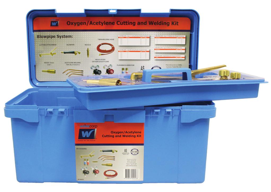

1 OPERATING INSTRUCTIONS OXYGEN/ACETYLENE CUTTING AND WELDING KIT
2 ! WARNING: There are a number of inherent hazards in the use of oxy-fuel welding and cutting apparatus. It is therefore necessary that proper safety and operating procedures be understood prior to the use of such apparatus. Please read this booklet thoroughly and carefully before attempting to operate oxy-fuel welding and cutting apparatus. A thorough understanding of the proper safety and operating procedures will serve to minimise the hazards. This booklet is presented as a guide only to the safe and efficient operation of oxy-fuel welding, cutting and heating apparatus. This Oxygen/Acetylene Cutting and Welding Kit should only be used by Operators who are properly trained and qualified in the safe use of this type of equipment.
3 TABLE OF CONTENTS Page Safety Precautions 3-4 Oxygen/Acetylene Cutting and Welding Kit Contents 4 Setting up the Gas Cylinders 5 Setting up the Gas Regulators 6-8 Setting up and operation for welding application 8-11 Welding Technique 12 Welding Procedures Heating 14 Pressure Chart for Multi-Flame Oxygen/Acetylene Nozzles 14 Setting up and operation for cutting application Cutting Technique Welding Tip Data Charts 18 Operational and Performance Data 19 The parts of a Cutting Attachment and Brass Handle 20 The parts of a Regulator 21 Spare parts of a Regulator 21 Warranty 22
4 SAFETY PRECAUTIONS Flashback occurs when the flame burns back into the torch, and sustains itself within the mixer tube. This is caused by overheating the tip and torch mixer tube by backfiring. A shrill hissing or squealing noise will accompany a sustained flashback. Extinguish the flashback immediately by shutting off the preheat oxygen valve. Without oxygen the flame cannot burn inside the torch. For safe operation: NEVER use oil or grease around, or on any part of welding or cutting apparatus. Even a trace of oil or grease can cause a serious fire or explosion DO NOT use oxygen pneumatic tools to blow out lines or to dust off clothing NEVER convert a fuel regulator for oxygen use or vice versa. The same applies for hoses DO NOT try to use a gas cylinder without a suitable pressure reducing regulator NEVER stand directly in front of an oxygen regulator when you are turning on the cylinder valve DO NOT open an oxygen cylinder valve quickly. Turn the cylinder valve on very slowly until the maximum cylinder pressure registers on the regulator gauge. Then open the valve completely DO NOT open a cylinder valve until the regulator adjusting knob has been released. NEVER attach new or used hose to the torch without first blowing out the dust which otherwise may clog the torch DO NOT use worn, patched or multi-spliced hose that may leak or cause excessive loss of pressure. NEVER repair hose with friction tape, use proper hose splicers DO NOT open the fuel gas valve more than one turn NEVER test for gas leaks with a flame. Use soap and water DO NOT use undue force in trying to open or close a cylinder valve. Notify your gas supplier and have the cylinder replaced if valve is too tight or otherwise faulty OBSERVE fire prevention precautions and have a fire extinguisher handy at all times DO NOT try to fill a small cylinder from a large one. The operation is dangerous and requires specialised equipment NEVER heat a gas cylinder by placing a flame on the cylinder walls. It could cause the cylinder to explode DO NOT weld or cut without proper eye protection DO NOT try to repair torches or regulators unless you have been properly instructed. A wrong repair job can use a serious explosion Page 3

 Flashback arrestors (x2 regulator & x2 torch) Mixer Cutting nozzle (No.")
5 KEEP sparks away from hoses and cylinders DO NOT make a guess if you do not know. Get the correct answer from a qualified person DO NOT misuse your welding or cutting equipment, they are precision tools and will serve you a long time if properly used CLEAN tips regularly with the cleaner supplied DO NOT attempt to cut or weld petrol tanks KIT CONTENTS Weldcorp s Oxygen/Acetylene Cutting and Welding Kit includes: Torch handle Cutting attachment Oxygen regulator Acetylene regulator Welding nozzles (No. 8, 10, 12) Flashback arrestors (x2 regulator & x2 torch) Mixer Cutting nozzle (No. 12) Twin hose: 15FT x 1/4 Tip cleaner Welding goggles Single spark lighter Plastic Toolbox Page 4


6 SETTING UP THE GAS CYLINDERS Oxygen/Acetylene is the most commonly used combination of gases for welding and cutting. Oxygen is available in seamless steel cylinders, compressed to about 25,000 kpa. Standard size cylinders include 1.8m 3, 3.7m 3 and up to 7.5m 3 capacities. Acetylene is the most important fuel gas, because of its high flame temperature. Acetylene is generally available in clinders of approximately 1.5m 3, 3.7m 3 and up to 7.5m 3 at a pressure of about 1,725 kpa. Acetylene cylinders are painted maroon and oxygen cylinders black. 1. Place the oxygen and fuel gas cylinders together where they are to be used and secure them from falling After securely positioning the cylinders, remove the plastic dust cap inserted in the oxygen cylinder valve. The cylinder valve threads are examined and cleaned at the point of refilling and therefore are supplied in good condition. Use of any cloth to further clean the valve threads should not be necessary. In fact, if any cloth with oil or grease traces is used, it could prove very dangerous. Slightly open (called cracking ) the oxygen and fuel gas cylinder valves to make sure they do not stick and to blow out any dirt or dust lodged in the valve. Close the valve. Page 5

7 SETTING UP THE REGULATORS 4. Be sure that the regulator inlet connection is absolutely clean and free of all traces of dirt, grease, etc. Mount the oxygen regulator to the oxygen cylinder valve using the open end spanner of the correct size. Do not use excessive force, but tighten the regulator connection nut firmly. NOTE: Be sure the regulator adjusting knob is in the out position. The adjusting knob is turned anti-clockwise to release the tension on the regulating spring. Failure to do this could damage the regulator. 5. Open the oxygen cylinder valve SLOWLY so that the high pressure regulator gauge needle moves up slowly. A pressure of approximately 25,000 kpa will be registered (if the cylinder is full). Never stand directly in front of, or behind, a regulator when an oxygen valve is being opened. Stand to one side. After full pressure has been reached the valve should be opened one full turn. Should the valve or connection leak immediately close the valve again and notify the supplier. NOTE: Never use force on a cylinder value to either open or close it. If the valve will not open or close by hand notify the supplier and have the cylinder replaced. Mount the fuel gas (acetylene) regulator in the same manner as you did the oxygen regulator, noting that the connecting nut has a left hand thread. Page 6


8 SETTING UP THE REGULATORS NOTE: It is extremely important that before opening the gas cylinder valves with the regulators attached, you must always ensure the regulator control knobs are fully wound in the anti-clockwise position. Slowly open the cylinder valves so that the high pressure gauge needle moves up gradually. Never open the cylinder valves suddenly. Check for leaks. Failure to follow these measures will result in damage to both the diaphragm and gauges and void you warranty. 6. Connect the oxygen hose to the outlet of the oxygen regulator. The oxygen hose has right hand threaded connections. Turn the adjusting screw on the regulator clockwise until a reading of 35kPa shows on the low pressure gauge. Allow the oxygen to escape until you are sure the hose is clean on the inside. A new hose may have talcum powder in it to protect the hose lining whilst in storage. Dust, dirt and talcum power, if left in the hose, may enter the small gas passages in the torch and block them. This can lead to flashback. NOTE: Oxygen assists in the burning process. Do not allow free oxygen to flow for longer than is necessary Page 7

9 SETTING UP THE REGULATORS 6.1 Connect the fuel gas hose to the fuel gas regulator outlet*. The fuel gas hose has left handed thread connection. Blow out the hose in the same manner as with the oxygen hose. Remember, fuel gas will burn. Keep it away from flames whilst blowing out the hose. *NOTE: It is important to note that Acetylene Hoses, Regulators, Gauges and Flashback Arrestors CANNOT be interchanged with Propane Hoses, Regulators, Gauges & Flashback Arrestors. SETTING UP & OPERATION FOR WELDING APPLICATION 7. Connect the free ends of the oxygen and fuel gas hoses to the welding torch you are to use. NOTE: Torch connections are clearly marked oxy or gas. Use of Flashback Arrestors (a safety device for use with fuel gases and oxygen) is highly recommended at all times. In Australian workplaces, it is mandatory that Flashback Arrestors are fitted at all times. These must conform to AS and be tested at a minimum interval of every 12 months. Refer to the Australian standard for further information. Page 8
10 SETTING UP & OPERATION FOR WELDING APPLICATION NOTE: Install flashback arrestors which are clearly marked: Oxygen regulator Oxygen torch Acetylene regulator Acetylene torch Flashback arrestors should be connected between the hose and each regulator and between the hose and the torch in the correct direction of flow which is clearly marked on the flashback arrestors. DO NOT OVER TIGHTEN AND CHECK FOR LEAKS AFTER INSTALLATION Assemble the appropriate mixer to the forward block of the torch handle. Note that the cone end of this mixer is provided with two sealing rings. A hand tight fit is all that is necessary for a gas tight joint. Select the tip size that is suitable for the job you are to do. Refer to the Welding Tip Selection Chart on page 18 of this manual. Open both oxygen and fuel gas cylinder valves in one complete turn. Partially open the torch oxygen valve and adjust the oxygen regulator until the pressure corresponds to the tip you have selected. Refer to the Welding Tip Size Pressures and Application Data on page 18 and 19 of this manual. Close the torch oxygen valve. Partially open the torch fuel gas valve and adjust the regulator pressure, using the chart similar to how the oxygen pressure was adjusted. Close the fuel gas valve. NOTE: Observe that the regulator pressure rises slightly when the torch valves are closed. This is the reason for setting the regulator at required pressure with the valve open. All pressure in welding and cutting charts are flowing pressures with torch valves open. Page 9


11 SETTING UP & OPERATION FOR WELDING APPLICATION NOTE: THE FOLLOWING INSTRUCTIONS COVER THE TORCH ADJUSTMENT PROCEDURES FOR ACETYLENE ONLY Hold the torch in one hand and the flint lighter in the other. Open the torch fuel gas valve approximately 1/2 turn and ignite the acetylene. Be sure to direct the flame away from persons, the cylinder or any flammable materials. Keep opening the fuel gas valve until the flame stops smoking an leaves the end of the tip about 3mm, and then reduce slightly to bring the flame back to the tip. 15. Open the torch oxygen valve until a bright inner cone appears on the flame. The point at which the feathery edges of the flame disappear and a sharp inner cone is visible is called the Neutral Flame. Keep adjusting the torch oxygen valve back and forth until you see a Neutral Flame. Page 10


12 SETTING UP & OPERATION FOR WELDING APPLICATION NOTE: THE FOLLOWING INSTRUCTIONS COVER THE TORCH ADJUSTMENT PROCEDURES FOR ACETYLENE ONLY. An Oxidising Flame is the flame that has an excess of oxygen. It is a pale blue colour without a clearly defined inner cone. The Carburising Flame is the flame you get before reaching the Neutral Flame. It is distinguished by its black carburising feather. Page 11
13 WELDING TECHNIQUE Two techniques can be employed for oxygen acetylene fusion welding - forehand or backhand. The forehand technique is usually recommended for welding material up to 3mm thickness because of better control of the smaller weld puddle, while backhand welding is generally more suitable for material 3mm and thicker. Increased speeds are possible with backhand welding and better control of the fusion at the root of the weld is normally achieved. 16. In the forehand technique, the welding rod precedes the tip in the direction in which the weld is being made. The flame is pointed in the direction of the welding, and is directed downward at an angle which preheats the edged of the joint. The torch tip and welding road are manipulated with oscillating motions to distribute the heat and molten metal uniformly. 17. In the backhand welding, the torch tip precedes the rod in the direction of the welding, and the flame is pointed towards the molten pool and completed weld. The end of the welding rod is placed in the flame between the tip and weld. Less manipulation is required in backhand welding than in forehand welding. The rod may be merely rolled from side to side or in semi-circles within the pool. The torch is usually held steady with little or no motion across the weld, while advancing slowly and evenly along the seam to be welded. WELDING PROCEDURES Several factors are common to all metals. Probably the most important of these is the expansion of metals on heating and contraction on cooling. When welding steel plates of relatively small size, allowances must be made for closing of the joint gap as the welding progresses. For steel, the gap of the weld joints should gradually increase by some 5mm in every 300mm. For copper and aluminium, the allowance should be larger than for steel, about in proportion to the coefficients of expansion for these metals as compared with steel. When welding assemblies, where alignment is important, the joints should be tack welded at frequent intervals. Good workmanship demands full penetration to the bottom of the joint and complete fusion along the sides of the joint. A reinforced bead, where applied should be of good contour and there should be no undercut along the sides of the weld bead profile. Page 12
14 WELDING PROCEDURES cont. Practically all fusion welding of ductile materials, such as wrought iron and alloy steels is performed in the same manner as that of low and medium carbon steels. Thus, the procedures recommended for these materials may be used as a guide for welding other materials where no specific instructions can be obtained. In the production of satisfactory joints, a slightly carburising flame can be used. The adjustment of the oxy-acetylene flame is simple and maybe maintained by observing the characteristics of the flame. The proper adjustment of the flame for other types of fuel gases is more difficult as no marked visible change in flame characteristics may occur. The outer envelope of the flame, not the inner cone, should be applied to the work. The Braze Welding technique is different from the one used in gas fusion welding. Torch preheating of adjacent material will depend upon size, shape and thermal conductivity of the metals and the joint configuration. Improper heating, primarily due to poor manipulation of the torch, may cause cracking, overheating and / or oxidation of the filler metal, as well as incomplete joint penetration. It is important that the joint be brought to a uniform temperature within the brazing temperature range that the filler metal flows freely and fills the joint. Overheating must be avoided and this is best accomplished by using an appropriate flux with a melting point not too far below the brazing temperature range of the filler metal. The melting of the flux can then serve as an indicator of the proper brazing temperature range of the filler metal. If the brazing filler metal is to be face-fed, it is touched to the joint as the heating progresses, until it melts and flows freely through the joint. Heating should then be stopped. This technique makes the joint area itself in effect a soldering iron and overheating is avoided. It is poor practice to apply the torch flame directly to the filler metal or flux for the purpose of force melting or flowing. It is advisable to maintain a uniform temperature at the joint. To accomplish this, auxiliary or multiple tip and multi flame torches may be necessary. In mechanised operations the parts can be moved, oscillated or rotated as they pass through the heating zone. Alternatively, the flames are moved around the parts to be brazed. In some operations, torches or burners are used to heat the parts over the entire joint area. In any case, the purpose is to obtain and maintain uniformity of metal temperature. Page 13
15 WELDING PROCEDURES cont. The filler metal is most commonly face-fed in manual torch brazing operations. In mechanised operations, proper design will permit the use of the pre-placed filler metal in the form of rings, washers, shims, paste or powder. However the pre-places filler metal should be positioned with respect to the flame so as not to be prematurely melted. HEATING 18. The preparation, flame adjustment and operation of the heating torch (nozzle) are the same as for welding. Brazing techniques utilising the multi-flame nozzle are described on the previous pages. The techniques for heating parts vary greatly and will depend upon metal, dimension, shape etc. However, the basic objectives of heating metal to uniform temperature are the same. RECOMMENDED PRESSURE CHART FOR MULTI-FLAME OXYGEN/ACETYLENE NOZZLES SETTING UP & OPERATION FOR CUTTING APPLICATION 19. Fit the cutting attachment to the torch handle. The cutting attachment cone end fits the welding torch head in the same manner as the welding tip mixer; hand tight with sealing rings. Connect hoses in the same manner as done with the welding torch. Select the type and size of cutting tip suitable to the work in hand and be sure the seating cone of the tip is not damaged and is free from all dirt before inserting into cutting attachment head. The cutting tip should be secured with a spanner using firm, but not excessive force. Fully open the oxygen valve on the welding torch handle. Page 14

16 SETTING UP & OPERATION FOR CUTTING APPLICATION 19.1 The lever actuated valve controls the cutting oxygen, which passes through the centre orifice of the tip. NOTE: Refer to the chart on page 19 of this manual for cutting tip section NOTE: THE FOLLOWING INSTRUCTIONS COVER THE TORCH ADJUSTMENT PROCEDURES FOR ACETYLENE ONLY. 20. Before lighting the torch, set the regulator pressure for each gas (using the pressure chart found on page 19 of this manual 21. IMPORTANT: Always purge out the cutting oxygen passages by pressing the cutting oxygen lever before lighting the torch. Open the fuel valve approximately 1/2 turn and ignite the gas with a flint lighter. Adjust the fuel valve until flame clears the end of the tip by about 3mm, and then reduce slightly to return the flame to the tip. Slowly open the preheat oxygen valve of the cutting attachment until a neutral flame has been established, depress the cutting oxygen lever. Note that the preheat flames changes slightly from the neutral setting. With the cutting oxygen level pressed readjust the preheat oxygen valve until the preheat flames are neutral again. IMPORTANT: Check where the molten metal and sparks land from cutting or welding. Serious fires and explosions have been caused by careless torch operations. TAKE ALL POSSIBLE PRECAUTIONS - have a fire extinguisher available - remove or protect flammable substances including: oxygen and acetylene hoses before starting work. Page 15
17 SETTING UP & OPERATION FOR CUTTING APPLICATION NOTE: THE FOLLOWING INSTRUCTIONS COVER THE TORCH ADJUSTMENT PROCEDURES FOR ACETYLENE ONLY. 22. Direct the inner cone of the preheat flames onto the spot where the cut is to be established, with the inner cones just clear of the surface. Take your time. Hold steady. Before the cutting action can start the steel must be preheated to a bright cherry read. When the red spot appears, slowly press the cutting oxygen lever. NOTE: If the lever is pressed too soon the flow of oxygen will chill the preheated area and prevent cutting. 23. When the cut has started, move the torch in the direction you wish to cut. Move too fast and you will lose the cut. Move too slow and the metal will fuse together. NOTE: The patch of the cut can be marked with chalk or centre punch marks. Hold the torch so that the cone ends of the preheat flames just clear of the metal. Hold the tip at right angles to work for straight cuts at the desired angle for bevel cuts. Take your time and do not move too fast or too slowly. Keep the tip out of the molten metal. 24. To pierce metal, hold the torch so that the preheat flame just clears the work. When the spot becomes a bright cherry red press down slowly on the oxygen cutting lever. 25. To prevent the sparks and the slag blowing toward you, tilt the torch tip slightly to one side so the sparks blow away from you and draw the torch head up slightly from work. When the metal is pierced, move the torch head steadily in the direction you wish to cut. If the metal does not pierce all the way through then not enough cutting oxygen is being used. Page 16
18 CUTTING TECHNIQUE Process of flame cutting Flame cutting of ferrous metals is primarily a chemical affinity of oxygen for ferrous metals above ignition temperatures. It is a process of preheating the material to be cut to its ignition temperature then rapidly oxidising it by means of a stream of oxygen issuing from a cutting tip. The jet forms a narrow slot or KERF in the metal. In addition to the chemical reaction, there is a very helpful mechanical eroding effect produced by the energy of the cutting oxygen stream which washes away approximately 30% of the metal in molten, unconsumed metallic form. After the cutting action starts, the torch unit is conveyed across the material to be cut at a speed sufficient to produce a continuous cutting action. This motion may be accomplished either manually or mechanically (with an automatic line or profile cutting machine). In manual cutting operations, the cutting tip is directed so the preheat flames and cutting jet stream concentrate in the area to be pierced or severed. Where a better quality of cut is desired, the operator may employ a guide for the torch to maintain a given tip-to-work distance and to move the torch along a given path evenly. A roller or wheel guide may also be employed to support the head of the torch, thereby leaving the operator free to direct the torch, at a fairly regular speed, along the line of cut. For cutting circles, a radius rod circle cutting attachment may be employed. When you finish your welding or cutting operation 1. First shut off the torch fuel gas valve, then shut off the torch oxygen valve. If this procedure is reversed a pop may occur. This pop throws carbon soot back into the torch and may, in time, partially block it. 2. Close both cylinder valves 3. Open the torch oxygen valve and let the oxygen lines drain out 4. Release the adjusting screw on the oxygen regulator 5. Open the torch fuel valve and release the pressure in the line 6. Release the adjusting screw on the fuel gas regulator Remember to set welding torch pressures according to the chart using approximately equal pressures. Sufficient pressure should be used at all times to ensure a dependable flame and freedom from popping. Excessive pressures generally waste gas more than they speed up the work. Ensure you use the right size tip for each job. Page 17

19 CUTTING TECHNIQUE Backfire and Flashback Backfire is a large pop or rattle caused by any of the following: Touching the work with the tip Operating the torch at a low fuel gas pressure A loose tip Dirt on the seating surface of the tip, mixer or head, causing a leak Overheating the tip WELDING TIP DATA CHARTS Tip Sizes 6-32 Tip Sizes 8x12 Page 18
20 Page 19 OPERATIONAL & PERFORMANCE DATA


21 The Parts of a Brass Handle The Parts of a Cutting Attachment Page 20

22 The Parts of a Regulator OXY-ACETYLENE WELDING & CUTTING KIT Regulator Spare Parts List Diagram Reference Number Part Description Oxygen Regulator Acetylene Regulator Page 21
23 1 YEAR WARRANTY Subject to the warranty conditions below, this Weldcorp product ( the Product ) is warranted by Cyclone Tools Pty Ltd ( the Company ) to be free from defects in material or workmanship for a period of 12 months from the date of original purchase ( the Warranty Period ). Under this warranty, the Company will, subject to the conditions below and at the Company s option, repair or replace the Product, or refund the purchase price of the Product, if such a defect becomes apparent during the Warranty Period. In the event of such a defect, the Product must be returned to the place of purchase, together with proof of purchase. Any handling and transportation (and other expenses) incurred in claiming under this warranty are not covered by this warranty and will not be borne by the Company. The Company s dealers or agents are not permitted to offer any warranty or guarantee on the Company s behalf in relation to the Product, except as expressly stated in this warranty. The Company s obligations under this warranty are subject to: (a) the Product having been used in accordance with the Company s directions, instructions and recommendations; (b) the Product having been used under normal conditions and with reasonable care (including in relation to the maintenance of the Product); (c) the Product not having been altered, tampered with or otherwise dealt with by any person in a manner other than as intended in respect of the Product. For the avoidance of doubt, this warranty does not cover damage, malfunction or failure resulting from misuse, neglect, abuse, or where the Product has been used for a purpose for which it was not designed or is not suited, or if repairs, alterations or modifications have been attempted by a person who is not an Authorised Service Agent of the Company. This warranty also does not apply to accidental damage or normal wear and tear. In addition to other rights and remedies that may be available under law, our goods come with guarantees that cannot be excluded under Australian Consumer Law (for consumers in Australia) and the Consumer Guarantees Act (for consumers in NZ). If you are a consumer in Australia, you are entitled to a replacement or refund for a major failure and compensation for any other reasonably foreseeable loss or damage. You are also entitled to have the goods repaired or replaced if the goods fail to be of acceptable quality and the failure does not amount to a major failure. If you are consumer in New Zealand, we will comply with our obligations to you under the Consumer Guarantees Act. Cyclone Tools Pty Ltd 73C Elizabeth Street Wetherill Park, New South Wales, 2164 Australia Ph: weldcorp-enq@cyclonetools.com Page 22
24 Manufactured in China Cyclone Tools Pty Ltd ABN C Elizabeth Street Wetherill Park NSW AUS Helpline:
OXY FUEL SYSTEM SET UP & SHUT DOWN PROCEDURE CHECKLIST ACETYLENE FUEL GAS
 OXY FUEL SYSTEM SET UP & SHUT DOWN PROCEDURE CHECKLIST ACETYLENE FUEL GAS Items needed for demonstrations: Fire extinguisher PPE (Personal Protective Equipment): o Lab coats/welding jackets o Leather gloves
INSTRUCTION MANUAL For Gas Welding, Cutting, Brazing & Heating Torches.
 THE HARRIS PRODUCTS GROUP INSTRUCTION MANUAL For Gas Welding, Cutting, Brazing & Heating Torches. IMPORTANT: For your own safety read these instructions. Failure to do so can lead to serious injury. www.harrisproductsgroup.com.au
Safety, Set-Up, and Operating Instructions
 Read all Instruction, SAVE THESE INSTRUCTION Safety, Set-Up, and Operating Instructions Gas Welding, Cutting, Brazing & Heating There are many hazards to be considered when using oxy-fuel welding, cutting,
Welding. Module
 Welding Module 19.2.4 Module 19.2.4 Describe the oxy fuel gas welding process. Process: setting up the equipment, leak testing, oxy-fuel gas mixing, flame adjustment (including oxidizing, neutral and carburizing
Visit our Web site: http: //
 CONTENTS: Medium Duty Victor Style Welding And Cutting Outfit MANUFACTURED BY AN ISO 9001 REGISTERED FIRM Visit our Web site: http: // www.northerntool.com TABLE OF CONTENTS Page INTRODUCTION... 1 SECTION
SAFETY AND OPERATION MANUAL
 SAFETY AND OPERATION MANUAL Congratulations on purchasing the GASPONY 1 Portable Welding/Cutting Outfit! This manual is designed to help you get the most out of your GASPONY 1. CAREFULLY REVIEW ALL SAFETY
TRADE OF HEAVY VEHICLE MECHANIC
 TRADE OF HEAVY VEHICLE MECHANIC PHASE 2 Module 1 Induction/Customer Care/Bench Fitting/Welding UNIT: 5 Table of Contents Aims and Objectives... 1 Learning Outcome:... 1 Setting up an Oxyacetylene torch...
OXYGEN ACETYLENE WELDING & CUTTING EQUIPMENT
 OXYGEN ACETYLENE WELDING & CUTTING EQUIPMENT Introduction: The oxy-acetylene torch can be used for various tasks. It can be used for cutting steel, welding steel, brazing and for heating metal. The oxy-acetylene
OXYGEN & ACETYLENE: Safety & Handling for these Highly Combustible Gases
 OXYGEN & ACETYLENE: Safety & Handling for these Highly Combustible Gases TRAINING SOURCE: Safety Division, Central Welding Supply, www.centralwelding.com Oxygen & Acetylene Safety Topics covered Oxygen:
oxyacetylene welding/cutting torch set
 instructions for oxyacetylene welding/cutting torch set model no: SGA2.V2 & SGA6.V2 Thank you for purchasing a Sealey product. Manufactured to a high standard, this product will, if used according to these
What is Oxy-Fuel Welding?
 Oxy-Fuel Welding What is Oxy-Fuel Welding? Process the fuses metal together Does not require electricity Uses a torch and filler rod Similar equipment as Oxy-Fuel Cutting Where is Oxy-Fuel Welding used?
Safe Work Instructions For Oxygen Acetylene Equipment
 Safe Work Instructions For Oxygen Acetylene Equipment Policy Sponsor: Assistant Vice President Facilities Management Responsible Unit: Trade Services Approval Date: September 2010 Revisions: January 2018
Oxy-Fuel Safety Training. Participant s Guide
 Oxy-Fuel Safety Training Page 1 of 19 Contents What s Included?... 3 Oxy-Fuel Safety Training Objectives... 4 Chapter 1: Safety & Responsibility... 6 Chapter 2: Gases in the Work Area... 7 Chapter 3: Equipment
V-24 OXYGEN LANCE VALVE
 INSTRUCTIONS for F-4737-U May, 2009 V-24 OXYGEN LANCE VALVE w/ C -Size Inlet w/ B -Size Inlet V-24 Oxygen Lance with 1/8" Pipe Holder... 9728D65... 2218939 V-24 Oxygen Lance with 1/4" Pipe Holder... 9728A65...
TURBO SET 1000 E D $'9 5(9
 TURBO SET 1000 Instructions for use and maintenance HOW TO GAS WELD WITH TURBO SET 1000 With gas welding always work methodically : before starting a weld ensure that the parent metal in the weld area
ASSEMBLY & OPERATIONS MANUAL. Straight & Clean Torch Cuts. Every Time.
 ASSEMBLY & OPERATIONS MANUAL Straight & Clean Torch Cuts. Every Time. CAUTION ALWAYS USE FLASH BACK ARRESTORS (purchased separately) READ THIS BOOK THOROUGHLY AND FOLLOW INSTRUCTIONS! FAILURE TO USE OSHA
Foundations of Agriculture
 Foundations of Agriculture Auto body and Restoration Repairs on small parts Portable welding OAW was the first type of portable welder Acetylene is mixed with oxygen in correct proportions and ignited.
CUTTING TORCH SAFETY. The Safe Use and Handling of OXY Fuel Cutting, Welding, and Heating Equipment
 CUTTING TORCH SAFETY The Safe Use and Handling of OXY Fuel Cutting, Welding, and Heating Equipment Introduction Safe operation for the use of gas cutting, heating and welding requires a clear understanding
PARTS, SERVICE & REPAIR BULLETIN
 CA4- PARTS, SERVICE & REPAIR BULLETIN 400 SERIES HEAVY DUTY CUTTING ATTACHMENT, TIP SERIES Manual No: 0056-379 Issue Date: August 2, 203 Revision: AB VictorTechnologies.com Table of Contents SECTION :
4 Machine maintenance and repair
 3.3 lift device consists of: lift motor, lead screw, guide rod, lifting seat Lift motor Lead screw Guide rod Lifting seat Diagram 3.3 3.4 torch holder set The torch holder consist of holder connection,
MODULE 3 THE BRAZING PROCESS
 MODULE 3 THE BRAZING PROCESS ISSUED BY REVISION NUMBER REVISION DATE DOCUMENT NUMBER S. GINBEY 0 5 th May 2014 QP74 Module 3 The Brazing Process Preparation of joints and materials The removal of all oxides
PARTS, SERVICE & REPAIR BULLETIN
 WH4C PARTS, SERVICE & REPAIR BULLETIN 400 SERIES HEAVY DUTY WELDING HANDLE Manual No: 0056-3763 Issue Date: October 07, 03 Revision: AA VictorTechnologies.com Table of Contents SECTION : GENERAL SAFETY
fig.1 Instructions for: Gas welding/cutting kit
 Instructions for: Gas welding/cutting kit MOdel No: SGA1.v3 Thank you for purchasing a Sealey product. Manufactured to a high standard this product will, if used according to these instructions and properly
INSTRUCTION MANUAL. Models: OX2550KC WK5500OX DO NOT DISCARD THESE WARNINGS AND INSTRUCTIONS
 DANGER INSTRUCTION MANUAL OXY-MAP Torches Models: OX2550KC WK5500OX EXTREMELY FLAMMABLE GASES USED WITH TORCH FIRE/EXPLOSION HAZARD CARBON MONOXIDE HAZARD This Oxygen Cutting and Welding Torch is unlike
FLAME CUTTING HANDBOOK
 FLAME CUTTING HANDBOOK 2 BUG-O SYSTEMS BUG-O Systems Kits are assembled from modular components. Each kit was originally an adaptation to meet an actual problem. The concept is both practical and economical,
Description. Lesson Outcomes. Assumptions. Terminology. Welding. Automotive
 Description Oxyacetylene or fusion welding is one of the oldest methods of joining metal. Oxyacetylene welding equipment is very common in an automotive shop and has many uses. It is most often used to
welding torches [all models]
![welding torches [all models]](/thumbs/78/78718045.jpg "welding torches [all models]") OPERATING INSTRUCTIONS welding torches [all models] WARNING! READ CAREFULLY AND COMPLETELY BEFORE USING EQUIPMENT. KEEP FOR REFERENCE. NOTICE: throughout this publication, Dangers, Warning and Cautions
OPERATING INSTRUCTIONS welding torches [all models] WARNING! READ CAREFULLY AND COMPLETELY BEFORE USING EQUIPMENT. KEEP FOR REFERENCE. NOTICE: throughout this publication, Dangers, Warning and Cautions
UNDER A SPECIFIC HEAT PROCESS, two pieces of material
 Applying Fuel Gas Welding (FGW) Processes and Techniques UNDER A SPECIFIC HEAT PROCESS, two pieces of material can be fused or joined together. This is the principal function of ing. Metal is commonly
Technical Operating Instructions for Magnum Cutting Systems. for online instructions
 Technical Operating Instructions for Magnum Cutting Systems http://www.magnumusa.com/operating-video.html for online instructions In Case of Emergency Immediately Call for Medical Aid. Familiarize yourself
Machine Cutting Torches Series 4700
 ADI 1580-E Certified ISO 9000 Machine Cutting Torches Series 4700 INSTRUCTIONS Before Installing, Operating or Servicing Read and Comply With These Instructions This symbol on the product means the product
General Precautions for handling compressed gases
 General Precautions for handling compressed gases Introduction Compressed gas cylinders can be extremely hazardous when misused or abused. Compressed gas cylinders can present a variety of hazards due
RARS5000 AIR BODY SAW OWNER S OPERATING MANUAL
 RARS5000 AIR BODY SAW OWNER S OPERATING MANUAL DESCRIPTION 1. No mar 2. No mar tip 3. Housing grip 4. Trigger 5. Air inlet 6. Air inlet plug 7. Plastic board Important! It is essential that you read the
Cal/OSHA T8 CCR 1536 Cal/OSHA T8 CCR 4799 Cal/OSHA T8 CCR 4845 Cal/OSHA T8 CCR 4848
 Cal/OSHA Gas Systems for Welding GAS WELDING Cal/OSHA T8 CCR 1536 Cal/OSHA T8 CCR 4799 Cal/OSHA T8 CCR 4845 Cal/OSHA T8 CCR 4848 When performing gas welding, the following precautions, work procedures,
Welding & Cutting Guide
 Welding & Cutting Guide BOC products perform with reliability and the backing of Australia s leading welding supplier Introduction This guide provides the basic knowledge required for using the gas welding,
2 GALLON TWIN STACK AIR COMPRESSOR W/ HOSE REEL
 2 GALLON TWIN STACK AIR COMPRESSOR W/ HOSE REEL Model: 52024 CALIFORNIA PROPOSITION 65 WARNING: You can create dust when you cut, sand, drill or grind materials such as wood, paint, metal, concrete, cement,
Tri-Safem Model I1 Regulator. INSTRUCTIONS and PARTS
 Tri-Safem Model I1 Regulator INSTRUCTIONS and PARTS USER RESPONSIBILITY This equipment will perform in conformity with the description thereof contained In this manual and accompanying labels andlor inserts
Working Environment Safety Assessment
 For your own safety and/or safety of your workforce, and to improve the efficiency of your business practices, you should be aware of, and be up to date with, the key safety issues and good practices relevant
CLEMENTS. ANA Oxygen Regulator with Yoke Connector. User Manual. Manual No. ANA Issue 1
 ANA 74300 Oxygen Regulator with Yoke Connector User Manual Manual No. ANA 74300 001 Issue 1 Safety Thank you for purchasing this Clements Oxygen Regulator. For your safety it is imperative that this unit
Auto-Rewind Hose Reels INSTRUCTION MANUAL FOR OXY-LPG MODEL
 Auto-Rewind Hose Reels INSTRUCTION MANUAL FOR OXY-LPG MODEL Introduction Thank you for purchasing a Retracta Auto Rewind Hose Reel. The Retracta range of hose reels are a breakthrough in industrial quality
AQUARIUS. Operating Instructions for the. Type 70 Electrolytic Gas Soldering / Welding Unit. Table of Contents
 AQUARIUS Operating Instructions for the Type 70 Electrolytic Gas Soldering / Welding Unit Table of Contents 1. Important General Remarks 2 2. Safety Instructions 2 3. Description of the Soldering Unit
SPECIFICATIONS Type: Twin stack, single phase Tank: 4 gallon Air Output: PSI; PSI Max PSI: 125 PSI HP: 1.
 2 GALLON TWIN STACK AIR COMPRESSOR Model: 9526 DO NOT RETURN TO STORE. Please CALL 800-348-5004 for parts and service. CALIFORNIA PROPOSITION 65 WARNING: You can create dust when you cut, sand, drill or
Hotspotter. Model WB-100 Professional Series. Assembly, Testing & Operating Instructions. Safety Information:
 Hotspotter Model WB-100 Professional Series Assembly, Testing & Safety Information: Safety publications related to safe practice and use: CSA 2-94 U.S. Requirements for Hand-Held LP Torches for use with
Item N o.: Item N am e:40cm Boys Rival Bike
 Item N o.:42272892 Item N am e:40cm Boys Rival Bike 9 bell 8 grip 30 crash pad 10 brake lever 26 wheel reflector 22 saddle 23 seat post 25 rear reflector 24 quick release 6 handle bar 7 stem 2 top tube
Gas Welding Hoses and connections, the weak link
 Gas Welding Hoses and connections, the weak link By Leif Andersen, Technical Product Manager Welding, WSS Regulators with flashback arrestors and the shank with its welding or cutting attachment are made
Mastar Outfits KL550-TR KL550-4P-T
 Ranked #1 for Commercial Refrigeration Technicians Mastar Highly rated by commercial refrigeration technicians, Mastar outfits contain all the necessary top of the line components for welding, cutting
Compressed Gases Storage and Handling Safety Policy. Individual Unit Function: Safety Procedure No.: SOP-0103 Page: 1 of 6
 Procedure No.: SOP-0103 Page: 1 of 6 MIDGA Reviewed: 07/09/18 Effective: 1/14/98 Supersedes: Original Preparer: Owner: Approver: Safety Safety Safety 1. PURPOSE The purpose of this procedure is to establish
U.S. CONCRETE, INC. SAFETY POLICY and PROCEDURE MANUAL
 SAFE -14 Page 1 of 8 U.S. CONCRETE, INC. SAFETY POLICY and PROCEDURE MANUAL FUNCTION Safety TOPIC Hotwork Permit Program OBJECTIVE(S): GENERAL POLICY: To provide a work atmosphere that is conducive to
A guide to Part 10 of the
 OCCUPATIONAL HEALTH AND SAFETY DIVISION Welding, Cutting, Burning and Soldering A guide to Part 10 of the Occupational Safety General Regulations October 2007 A GUIDE TO PART 10 WELDING, CUTTING, BURNING
AIR COMPRESSOR OPERATING INSTRUCTION AND PARTS LIST
 AIR COMPRESSOR OPERATING INSTRUCTION AND PARTS LIST OIL-LESS TYPE IMPORTANT: PLEASE READ CAREFULLY BEFORE STARTING OPERATIONS. THE CONTENTS ARE FOR GENERAL INFORMATION OF ALL THE SIMILAR MODELS. Record
INSTRUCTIONS FOR THE KOBUKI TORCH
 GLASS TORCH TECHNOLOGIES, INC. 55 N. Main Street, Tioga, Pa. 16946 (570) 835-9777 INSTRUCTIONS FOR THE KOBUKI TORCH To Attach your Lines to the Torch: The Gas Line goes on the stud located by the Red Valve.
PRESSURE CONTROL REGULATORS
 REGULATOR HARRIS STYLE SINGLE STAGE 201 Series Medium Duty Single stage construction Forged brass body for maximum strength Chrome bonnet Neoprene diaphragms Sintered metal inlet filter to trap impurities
INSPECTION of PORTABLE and OXY FUEL GAS SYSTEMS
 1.0 PURPOSE This work Instruction describes the procedure for the inspection, testing and identification requirements of portable and mobile oxy-fuel gas systems for welding, cutting, heating to ensure
cutting torches [all models]
![cutting torches [all models]](/thumbs/78/78718073.jpg "cutting torches [all models]") OPERATING INSTRUCTIONS cutting torches [all models] WARNING! READ CAREFULLY AND COMPLETELY BEFORE USING EQUIPMENT. KEEP FOR REFERENCE. NOTICE: throughout this publication, Dangers, Warning and Cautions
OPERATING INSTRUCTIONS cutting torches [all models] WARNING! READ CAREFULLY AND COMPLETELY BEFORE USING EQUIPMENT. KEEP FOR REFERENCE. NOTICE: throughout this publication, Dangers, Warning and Cautions
GAS BBQ 4 burner. instructions for. model no: BBQ10
 instructions for GAS BBQ 4 burner model no: BBQ10 Thank you for purchasing a Sealey product. Manufactured to a high standard, this product will, if used according to these instructions, and properly maintained,
INSTALLATION MANUAL Matheson Tri-Gas Cabinet Enclosures
 INSTALLATION MANUAL Matheson Tri-Gas Cabinet Enclosures MINT-0289-XX TABLE OF CONTENTS Limited Warranty... 3 User Responsibility... 3-4 General Service... 4 Safety Precautions.... 5 Physical Dimensions..
PRESSURE REDUCING STATION INSTALLATION, OPERATIONS & MAINTENANCE MANUAL
 PRESSURE REDUCING STATION INSTALLATION, OPERATIONS & MAINTENANCE MANUAL Company Registered Office: Crown House, Stockport, Cheshire, SK13RB No. 850 0700 67 Registered in England and Wales No. 05058855
COMMERCIAL ITEM DESCRIPTION TORCHES, OXYACETYLENE, HAND HELD, CUTTING AND WELDING
 INCH-POUND 2 July 2010 SUPERSEDING A-A-55826 5 September 1996 COMMERCIAL ITEM DESCRIPTION TORCHES, OXYACETYLENE, HAND HELD, CUTTING AND WELDING The General Services Administration has authorized the use
CHAPTER 26 WELDING AND CUTTING
 CHAPTER 26 WELDING AND CUTTING Revised 7/2010 1 WELDING AND CUTTING Responsibilities 1. The County Safety Officer is responsible for providing appropriate safety instructions for supervisor's use on welding
Wilkins Safety Group
 Gas Welding INTRODUCTION Welding is the union of pieces of metal by fusing the opposing surfaces that have been made molten by heat. Processes similar to welding include brazing and soldering. Allied processes
High Pressure Inlet Kits for CONCOA BlendMites and BlendMasters
 ADI 3210-A ADI 3210-A Certified ISO 9001 Certified ISO 9001 High Pressure Inlet Kits for CONCOA BlendMites and BlendMasters Warning: An appropriately sized pressure relief device downstream of the regulator
Operating manual. LINDOFLAMM Acetylene special burner LF-H series.
 Operating manual. LINDOFLAMM Acetylene special burner LF-H series. 02 Operating manual. LINDOFLAMM acetylene special burner. This operating manual is valid for the following models LF-H-4, 6, 8 and 16:
Yoke Block Instruction Manual
 Yoke Block Instruction Manual ! WARNING IMPORTANT: READ MANUAL COMPLETELY BEFORE OPERATING THIS DEVICE This manual contains instructions on periodically required checks to be performed by the user. These
Brazing. Turn up the. When brazing and soldering, most HVACR technicians
 Turn up the Brazing Heat A discussion about oxygen/acetylene vs. air/acetylene torches, including applications, comparisons, and base and filler metal suggestions. B y B o b H e n s o n a n d M i k e S
Welding, Cutting, and Brazing
 Welding, Cutting, and Brazing Hazards of Welding Operations Fire hazards Metal splatter Electric shock Explosion hazards Released gases Radiant energy Where would these hazards be found on oil and gas
Operator s Manual Heavy Duty Torch Kit VTK-HD-B
 Operator s Manual Heavy Duty Torch Kit VTK-HD-B WARNING: Do not assemble, install or operate this equipment without reading ALL of this manual and the safety precautions and warnings illustrated in this
Section 35 Brieser Construction SH&E Manual
 Brieser Construction SH&E Manual August 2017 Assure that employees handling compressed gases are adequately trained in the inherent hazards of the cylinders and their contents, as well as proper handling,
KTIndustries.net. Medium Duty Kit with Cylinders USER S MANUAL. and Portable Carrying Tote
 USER S MANUAL Medium Duty Kit with Cylinders and Portable Carrying Tote For K-T 31-5009 KTIndustries.net DOT Cylinder Included Warning: Read and understand all instructions before using! Severe personal
EXOTHERMIC TORCH ADAPTER. Instruction Manual
 EXOTHERMIC TORCH ADAPTER Instruction Manual CAUTION FLAME TECH ALWAYS RECOMMENDS USING FLASH BACK ARRESTORS (must purchase separately) Pre-operation Checklist Before you begin, the following routine checks
Medium-Duty Oxy-Acetylene Cutting and Welding Outfit
 OM-251 341B 2013 12 Processes Oxy-Fuel Welding and Cutting Description Accessory Medium-Duty Oxy-Acetylene Cutting and Welding Outfit 770 502 www.hobartwelders.com File: Accessory TABLE OF CONTENTS SECTION
AIR COMPRESSOR. Failure to follow all instructions as listed below may result in electrical shock, fire, and/or serious personal injury.
 2 GALLON AIR COMPRESSOR Model: 7517 DO NOT RETURN TO STORE. Please CALL 800-348-5004 for parts and service. CALIFORNIA PROPOSITION 65 WARNING: You can create dust when you cut, sand, drill or grind materials
CW-23, CW-23/FG-2, & CW-24-R CUTTING ATTACHMENTS
 INSTRUCTIONS for CW-23, CW-23/FG-2, & CW-24-R CUTTING ATTACHMENTS F-3135-O March, 2001 These INSTRUCTIONS are for experienced operators. If you are not fully familiar with the principles of operation and
Hot Compressed Air Lance Operation Manual. LAB Manufacturing 9483 Reading Road Cincinnati, OH (800)
") Hot Compressed Air Lance Operation Manual www.heatlances.com LAB Manufacturing 9483 Reading Road Cincinnati, OH 45215 (800) 776-5830 PARTS CHECK LIST NOTE: Check all fittings & connections prior to operation.
Hot Compressed Air Lance Operation Manual www.heatlances.com LAB Manufacturing 9483 Reading Road Cincinnati, OH 45215 (800) 776-5830 PARTS CHECK LIST NOTE: Check all fittings & connections prior to operation.
Installation and Operation Instructions
 Bentintoshape llc Installation and Operation Instructions Fire Pit - Hidden Tank Models www.bentintoshape.net INTRODUCTION Your bentintoshape Cor-Ten Steel Gas Fire Pit is designed for installation in
Item Name: 30CM GIRLS STAR THE UNICORN BIKE
 Item No.: 42333753 Item Name: 30CM GIRLS STAR THE UNICORN BIKE Contents 1. Parts identification 1 2. Safety precautions 2 3. Check list 6 4. Assembly 7 5. Adjustment 14 6. Repair and Service 15 7. Warranty
AC1810 / AC1810-A TECHNICAL SPECIFICATIONS. Operating Pressure psi ( kgs/cm²) [AC1810] Displacement. Net Weight
![AC1810 / AC1810-A TECHNICAL SPECIFICATIONS. Operating Pressure psi ( kgs/cm²) [AC1810] Displacement. Net Weight](/thumbs/83/88369739.jpg "AC1810 / AC1810-A TECHNICAL SPECIFICATIONS. Operating Pressure psi ( kgs/cm²) [AC1810] Displacement. Net Weight") Technical Specifications Operating Instructions Maintenance Information Troubleshooting Guide Parts Diagrams AC1810 / AC1810-A THE EVOLUTION OF PERFECTION CAUTION: Before attempting to use or service this
Technical Specifications Operating Instructions Maintenance Information Troubleshooting Guide Parts Diagrams AC1810 / AC1810-A THE EVOLUTION OF PERFECTION CAUTION: Before attempting to use or service this
453 Series Steam Heated Vaporizing Regulator
 ADI 0453A Certified ISO 9001:2000 453 Series Steam Heated Vaporizing Regulator INSTALLATION AND OPERATION INSTRUCTIONS Before Installing or Operating, Read and Comply with These Instructions Controls Corporation
Standard Gas Countertop Griddle
 Standard Gas Countertop Griddle This manual contains important information regarding your unit. Please read the manual thoroughly prior to equipment set-up, operation and maintenance. Failure to comply
BRAZING EQUIPMENT PORTAPAK KIT
 BRAZING EQUIPMENT PORTAPAK KIT Portapak Trolley Single Stage 2 Gauge Acetylene Regulator Single Stage 2 Gauge Oxygen Regulator Acetylene Flashback Arrestor Oxygen Flashback Arrestor 5 Meter Oxy / Acetylene
G7S Hand Pump Owner s Manual
 G7S Hand Pump Owner s Manual Copyright Air Venturi 2018 Version 4-18 Specifications 24.80 inches long closed 43.31 inches long extended 4500 psi/310 bar max pressure Features Integral manometer (pressure
CUTTING AND WELDING TORCHES HANDLES
 INSTRUCTIONS MANUAL GALA SOL, S.A. FABRICA DE APARATOS Y MAQUINAS DE SOLDADURA Y CORTE AUTOGENOS C/ ALBARRACIN 25-27 TFNO.: 976 513 055 FAX: 976 515 303 50015 ZARAGOZA e-mail: galasol@galasol.com GALA
AIR HAMMERS MODEL NO: CAT138/CAT139 OPERATING & MAINTENANCE INSTRUCTIONS PART NO: / GC064
 AIR HAMMERS MODEL NO: CAT138/CAT139 PART NO: 3120152 /3120153 OPERATING & MAINTENANCE INSTRUCTIONS GC064 INTRODUCTION Thank you for purchasing this CLARKE Air Hammer. Before attempting to use this product,
97C COMPRESSOR KIT 12V PART NO C COMPRESSOR KIT 24V PART NO C COMPRESSOR KIT PART NO
 97C COMPRESSOR KIT 12V PART NO. 00097 97C COMPRESSOR KIT 24V PART NO. 02497 98C COMPRESSOR KIT PART NO. 00098 97C 98C IMPORTANT: It is essential that you and any other operator of this product read and
24L AIR COMPRESSOR OPERATION & MAINTENANCE INSTRUCTIONS MODEL NO: RANGER 7/240 PART NO: LS0913
 24L AIR COMPRESSOR MODEL NO: RANGER 7/240 PART NO: 2242000 OPERATION & MAINTENANCE INSTRUCTIONS LS0913 INTRODUCTION Thank you for purchasing this CLARKE 24L Air Compressor. Please read this manual fully
24L AIR COMPRESSOR MODEL NO: TIGER 11/250 PART NO: OPERATION & MAINTENANCE INSTRUCTIONS LS01/13
 24L AIR COMPRESSOR MODEL NO: TIGER 11/250 PART NO: 2244010 OPERATION & MAINTENANCE INSTRUCTIONS LS01/13 INTRODUCTION Thank you for purchasing this product. Before attempting to use this product, please
Code AWC20HP Air Compressor
 Code 951816 AWC20HP Air Compressor Index of Contents Index of Contents 02 Declaration of Conformity 02 What s Included 03 Safety Precautions 03 Specifications (AWC20HP Air Compressor) 04 Assembly Instructions
USER GUIDE ROLLING WALKERS INSTRUCTIONS FOR USE JANUARY, Maximum User Weight: 170kg (Do not exceed this weight)
") USER GUIDE ROLLING WALKERS INSTRUCTIONS FOR USE JANUARY, 2013 Model Nos: BE07889T Maximum User Weight: 170kg (Do not exceed this weight) Model Nos: BE07890TB Maximum User Weight: 227kg (Do not exceed this
USER GUIDE ROLLING WALKERS INSTRUCTIONS FOR USE JANUARY, 2013 Model Nos: BE07889T Maximum User Weight: 170kg (Do not exceed this weight) Model Nos: BE07890TB Maximum User Weight: 227kg (Do not exceed this
WELDING AND CUTTING GUIDELINES
 Page 1 of 8 University employees should observe the following general safety guidelines when performing hot work operations. Also see the Hot Work Guidelines EH&S 02-008. Hot work is defined as: brazing,
24L OIL FREE AIR COMPRESSOR MODEL NO: TIGER 7/250 PART NO: OPERATION & MAINTENANCE INSTRUCTIONS LS10/13
 24L OIL FREE AIR COMPRESSOR MODEL NO: TIGER 7/250 PART NO: 2244030 OPERATION & MAINTENANCE INSTRUCTIONS LS10/13 INTRODUCTION Thank you for purchasing this product. Before attempting to use this product,
ACCUCRAFT UK LTD Unit 4, Long Meadow Industrial Estate, Pontrilas, Herefordshire. HR2 0UA Tel:
 1 ACCUCRAFT UK LTD Unit 4, Long Meadow Industrial Estate, Pontrilas, Herefordshire. HR2 0UA Tel: 01981 241380 www.accucraft.uk.com SAFETY FIRST OPERATING INSTRUCTIONS FLYING SCOTSMAN All our locomotives
VERTICAL AIR COMPRESSORS
 VERTICAL AIR COMPRESSORS MODEL NO: VE15C150, VE18C150, VE25C150 PART NO: 2226010, 2226020, 2226025 OPERATION & MAINTENANCE INSTRUCTIONS LS0715 INTRODUCTION Thank you for purchasing this CLARKE Vertical
Gas Countertop Hot Plates
 Gas Countertop Hot Plates This manual contains important information regarding your Patriot unit. Please read the manual thoroughly prior to equipment set-up, operation and maintenance. Failure to comply
Bauman Machine Inc. COMPRESSED GAS CYLINDER SAFETY
 Bauman Machine Inc. COMPRESSED GAS CYLINDER SAFETY Many industrial and laboratory operations require the use of compressed gases for a variety of different operations. Compressed gases present a unique
CHEMICAL INDUCTION KIT (Pt.No Issue 6, October 2015)
") CHEMICAL INDUCTION KIT (Pt.No.2400-0740 Issue 6, October 2015) DESCRIPTION The C-Dax Chemical Induction Kit is an accessory kit for the GoldLine range of three point linkage sprayers. The system operates
CHEMICAL INDUCTION KIT (Pt.No.2400-0740 Issue 6, October 2015) DESCRIPTION The C-Dax Chemical Induction Kit is an accessory kit for the GoldLine range of three point linkage sprayers. The system operates
100L AIR COMPRESSOR MODEL NO: TIGER 16/1010 PART NO: OPERATION & MAINTENANCE INSTRUCTIONS LS01/13
 100L AIR COMPRESSOR MODEL NO: TIGER 16/1010 PART NO: 2244025 OPERATION & MAINTENANCE INSTRUCTIONS LS01/13 INTRODUCTION Thank you for purchasing this product. Before attempting to use this product, please
U S E R M A N U A L CAUTION. SAVE THESE INSTRUCTIONS Federal (USA) law restricts this device to sale by or on the order of a physician.
 law restricts this device to sale by or on the order of a physician.") U S E R M A N U A L 1600 SERIES OXYGEN REGULATOR 168715G (Shown) SAVE THESE INSTRUCTIONS Federal (USA) law restricts this device to sale by or on the order of a physician. 300 Held Drive Tel: (+001) 610-262-6090
U S E R M A N U A L 1600 SERIES OXYGEN REGULATOR 168715G (Shown) SAVE THESE INSTRUCTIONS Federal (USA) law restricts this device to sale by or on the order of a physician. 300 Held Drive Tel: (+001) 610-262-6090
FILTER REGULATORS MODEL NO: CAT155 & CAT156 FITTING & MAINTENANCE INSTRUCTIONS PART NO: & ORIGINAL INSTRUCTIONS
 FILTER REGULATORS MODEL NO: CAT155 & CAT156 PART NO: 3120169 & 3120170 FITTING & MAINTENANCE INSTRUCTIONS ORIGINAL INSTRUCTIONS GC0117 INTRODUCTION Thank you for purchasing this CLARKE Filter/Regulator.
VERTICAL AIR COMPRESSORS
 VERTICAL AIR COMPRESSORS MODEL NO: VE11C150, VE15C150, VE18C150 PART NO: 2226005, 2226000, 2226015 OPERATION & MAINTENANCE INSTRUCTIONS LS0615 INTRODUCTION Thank you for purchasing this CLARKE Vertical
Operator s Manual AFA-1, AFA-2, & AFP-1 Torch Kits
 Operator s Manual AFA-1, AFA-2, & AFP-1 Torch Kits AFA-1 (50210) Torch kit AFA-2 (50211) Torch Kit AFP-1 (50212) Torch kit WARNING: Do not assemble, install, or operate this equipment without reading ALL
PRESSURISED PAINT CONTAINER
 PRESSURISED PAINT CONTAINER MODEL NO: CPP2B PART NO: 3082115 OPERATION & MAINTENANCE INSTRUCTIONS GC0913 INTRODUCTION Thank you for purchasing this CLARKE Pressurised Paint Container. Before attempting
Trade of Plumbing. Module 1: Thermal Process and Mild Steel Pipework Unit 9: Oxy-Acetylene Welding Safety and Plant Phase 2
 Trade of Plumbing Module 1: Thermal Process and Mild Steel Pipework Unit 9: Oxy-Acetylene Welding Safety and Plant Phase 2 Table of Contents List of Figures... 5 List of Tables... 6 Document Release History...