INSTALLATION AND OPERATION MANUAL
|
|
|
- Abraham Butler
- 6 years ago
- Views:
Transcription


1 EUROPEAN USERS 400V 0Hz SUPPLY DETAILS ARE IN- CLUDED WITH ELECTRICAL CONTROL BOX. DISREGARD SUPPLY WIRING DETAILS IN THIS MANUAL INSTALLATION AND OPERATION MANUAL 9,000 POUND CAPACITY COMMERCIAL GRADE FOUR-POST LIFTS IMPORTANT SAFETY INSTRUCTIONS SAVE THESE INSTRUCTIONS PLEASE READ THE ENTIRE CONTENTS OF THIS MANUAL PRIOR TO INSTALLATION AND OPERATION. BY PROCEEDING YOU AGREE THAT YOU FULLY UNDERSTAND AND COMPREHEND THE FULL CONTENTS OF THIS MANUAL. FORWARD THIS MANUAL TO ALL OPERATORS. FAILURE TO OPERATE THIS EQUIPMENT AS DIRECTED MAY CAUSE INJURY OR DEATH. Manual REV G pn# MODELS: HD-9ST HD-9 VERSION J VERSION K HD-9STX VERSION J HD-9XW HD-9XL VERSION K VERSION D ORIGINAL INSTRUCTIONS IN ENGLISH LANGUAGE RECEIVING The shipment should be thoroughly inspected as soon as it is received. The signed Bill of Lading is acknowledgement by the shipping carrier as receipt of this product as listed in your invoice as being in a good condition of shipment. If any of these goods listed on this Bill of Lading are missing or damaged, do not accept goods until the shipping carrier makes a notation on the freight bill of the missing or damaged goods. Do this for your own protection. Keep this operation manual near the machine at all times. Make sure that ALL USERS read this manual. BE SAFE Your new lift was designed and built with safety in mind. However, your overall safety can be increased with proper training and thoughtful operation on the part of the operator. DO NOT operate or repair this equipment without reading this manual and the important safety instructions shown inside. Keep this operation manual near the lift at all times. Make sure that ALL USERS read and understand this manual. 164 Lemonwood Dr. Santa Paula, CA , USA Toll Free Tel: Fax:
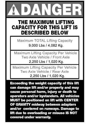
2 9,000 POUND CAPACITY, COMMERCIAL GRADE FOUR POST AUTO / TRUCK LIFT This instruction manual has been prepared especially for you. Your new lift is the product of over 40 years of continuous research, testing and development; it is the most technically advanced lift on the market today. READ THIS ENTIRE MANUAL BEFORE INSTALLATION & OPERATION BEGINS. RECORD HERE THE LIFT AND POWER UNIT INFORMATION WHICH IS LOCATED ON THE SERIAL NUMBER DATA PLATES ON THE LIFT AND ON THE POWER UNIT Power Unit Model # Power Unit Date Of Mfg. Power Unit Serial # Max Operating Pressure 2,460 PSI This information is required when calling for parts or warranty issues. Model Number Lifting Capacity Serial Number Date of Manufacture Power Unit Number Volt. / Ph. / Freq. / Amp. Description Rolling Jack Max. Air Pressure Max. Cable Dia. Conn. Dia. Cable Lengths DANGER! Disconnect Power Before Servicing. MT20 A B Santa Paula, CA USA C D WARRANTY VOID IF DATA PLATE IS REMOVED. MADE IN CHINA PRODUCT WARRANTY Our comprehensive product warranty means more than a commitment to you; it s also a commitment to the value of your new BendPak lift. For full warranty details and to register your new lift contact your nearest BendPak dealer or visit / support/ warranty/ NOTE: Every effort has been taken to ensure complete and accurate instructions have been included in this manual, however, possible prod- tions without incurring any obligation for equipment previously or subsequently sold. Not responsible for typographical errors. 2
3 IMPORTANT NOTICE! Do not attempt to install this lift if you have never been trained on basic automotive lift installation procedures. Never attempt to lift components without proper lifting tools such as forklift or cranes. Stay clear of any moving parts that can fall and cause injury. These instructions must be followed to ensure proper installation and operation of your lift. Failure to comply with these instructions can result in serious bodily harm and void product warranty. Manufacturer will assume no liability for loss or damage of any kind, expressed or implied resulting from improper installation or use of this product. PLEASE READ ENTIRE MANUAL PRIOR TO INSTALLATION. DEFINITIONS OF HAZARD LEVELS Identify the hazard levels used in this manual with the following definitions and signal words: OWNER S RESPONSIBILITY To maintain the lift and user safety, the responsibility of the owner is to read and follow these instructions: Follow all installation and operation instructions. Make sure installation conforms to all applicable Local, State, and Federal Codes, Rules, and Regulations; such as State and Federal OSHA Regulations and Electrical Codes. Carefully check the lift for correct initial function. Read and follow the safety instructions. Keep them readily available for machine operators. Make certain all operators are properly trained, know how to safely and correctly operate the unit, and are properly supervised. Allow unit operation only with all parts in place and operating safely. Carefully inspect the unit on a regular basis and perform all maintenance as required. Service and maintain the unit only with authorized or approved replacement parts. Keep all instructions permanently with the unit and all decals on the unit clean and visible. BEFORE YOU BEGIN DANGER! Watch for this symbol: It Means: Immediate hazards which will result in severe personal injury or death. WARNING! Watch for this symbol: It Means: Hazards or unsafe practices which could result in severe personal injury or death. CAUTION! Watch for this symbol: It Means: Hazards or unsafe practices which may result in minor personal injury, product or property damage. Receiving: The shipment should be thoroughly inspected as soon as it is received. The signed bill of lading is acknowledgement by the carrier of receipt in good condition of shipment covered by your invoice. If any of the goods called for on this bill of lading are shorted or damaged, do not accept them until the carrier makes a notation on the freight bill of the shorted or damaged goods. Do this for your own protection. NOTIFY THE CARRIER AT ONCE if any hidden loss or damage is discovered after receipt and request the carrier to make an inspection. If the carrier will not do so, prepare a signed statement to the effect that you have notified the carrier (on a specific date) and that the carrier has failed to comply with your request. IT IS DIFFICULT TO COLLECT FOR LOSS OR DAMAGE AFTER YOU HAVE GIVEN THE CARRIER A CLEAR RECEIPT. File your claim with the carrier promptly. Support your claim with copies of the bill of lading, freight bill, invoice, and photographs, if available. Our willingness to assist in helping you process your claim does not make BendPak responsible for collection of claims or replacement of lost or damaged materials. 3
4 Contents TABLE OF CONTENTS Page No. Warranty / Serial Number Information Owner s Responsibility Before You Begin Installer Operator/ Protective Equipment Introduction Safety / Warning Instructions Tools Required Step 1 / Selecting Site Step 2 / Floor Requirements Assembly View / Description of Parts Clearances Power Unit Location Step 3 / Column and Cross Tube Installation Step 4 / Raising the Cross Tubes Step / Powerside Runway Installation Step 6 / Offside Runway Installation Step 7 / Cable Sheave Installation Step 8 / Cable Installation Step 9 / Power Unit Installation Step 10 / Routing Hydraulic Hoses Step 11 / Routing Air Lines Safety Airline Routing Step 12 / Power Unit Hook Up Step 13 / Inspecting Slack Safety Springs Step 14 / Lift Start Up/Final Adjustments Step 1 / Anchoring The Columns Step 16 / Attaching Approach Ramps/Tire stops Step 17 / Leveling/Synchronizing Step 18 / Bleeding Optional Equipment Installation Step 19 / Operation Instructions Step 20 / Lift Operation Safety Maintenance & 43 Troubleshooting Guide Maintenance Records Installation Form Part Number Lists

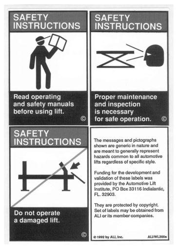
5 INSTALLER / OPERATOR PLEASE READ AND FULLY UNDERSTAND. BY PROCEEDING YOU AGREE TO THE FOLLOWING. I have visually inspected the site where the lift is to be installed and verified the concrete to be in good condition and free of cracks or other defects. I understand that installing a lift on cracked or defective concrete could cause lift failure resulting in personal injury or death. I understand that a level floor is required for proper installation and level lifting. I understand that I am responsible if my floor is of questionable slope and that I will be responsible for all charges related to pouring a new level concrete slab if required and any charges. I understand that the lifts are supplied with concrete fasteners meeting the criteria of the American National Standard Automotive Lifts - Safety Requirements for Construction, Testing, and Validation ANSI/ALI ALCTV- 2011, and that I will be responsible for all charges related to any special regional structural and/or seismic anchoring requirements specified by any other agencies and/or codes such as the Uniform Building Code (UBC) and/or International Building Code (IBC). I will assume full responsibility for the concrete floor and condition thereof, now or later, where the above equipment model(s) are to be installed. Failure to follow danger, warning, and caution instructions may lead to serious personal injury or death to operator or bystander or damage to property. I understand that Bendpak lifts are designed to be installed in indoor locations only. Failure to follow installation instructions may lead to serious personal injury or death to operator or bystander or damage to property or lift. Failure to follow danger, warning, and caution instructions may lead to serious personal injury or death to operator or bystander or damage to property. Please read entire manual prior to installation. Do not operate this machine until you read and understand all the dangers, warnings and cautions in this manual. For additional copies or further information, contact: BendPak Inc. / Ranger Products 164 Lemonwood Dr. Santa Paula, CA INSTALLER / OPERATOR PROTECTIVE EQUIPMENT Personal protective equipment helps makes installation and operation safer, however, it does not take the place of safe operating practices. Always wear durable work clothing during any installation and/or service activity. Shop aprons or shop coats may also be worn, however loose fitting clothing should be avoided. Tight fitting leather gloves are recommended to protect technician hands when handling parts. Sturdy leather work shoes with steel toes and oil resistant soles should be used by all service personnel to help prevent injury during typical installation and operation activities. Eye protection is essential during installation and operation activities. Safety glasses with side shields, goggles, or face shields are acceptable. Back belts provide support during lifting activities and are also helpful in providing worker protection. Consideration should also be given to the use of hearing protection if service activity is performed in an enclosed area, or if noise levels are high. THIS SYMBOL POINTS OUT IMPORTANT SAFETY INSTRUCTIONS WHICH IF NOT FOLLOWED COULD ENDANGER THE PERSONAL SAFETY AND/OR PROPERTY OR YOURSELF AND OTHERS AND CAN CAUSE PERSONAL INJURY OR DEATH. READ AND FOLLOW ALL INSTRUCTIONS IN THIS MANUAL BEFORE ATTEMPTING TO OPERATE THIS MACHINE.


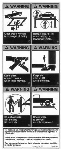
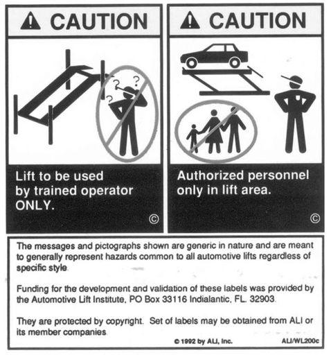
6 INTRODUCTION 1. Carefully remove the crating and packing materials. CAUTION! Be careful when cutting steel banding material as items may become loose and fall causing personal harm or injury. 2. Check the voltage, phase and proper amperage requirements for the motor shown on the motor plate. Wiring should be performed by a certified electrician only. IMPORTANT SAFETY INSTRUCTIONS! Read these safety instructions entirely! IMPORTANT NOTICE! Do not attempt to install this lift if you have never been trained on basic automotive lift installation procedures. Never attempt to lift components without proper lifting tools such as forklift or cranes. Stay clear of any moving parts that can fall and cause injury. 1. READ AND UNDERSTAND all safety warning procedures before operating lift. 2. KEEP HANDS AND FEET CLEAR. Remove hands and feet from any moving parts. Keep feet clear of lift when lowering. Avoid pinch points. 3. KEEP WORK AREA CLEAN. Cluttered work areas invite injuries. 4. Consider work area environment. Do not expose equipment to rain. DO NOT use in damp or wet locations. Keep area well lighted.. ONLY TRAINED OPERATORS should operate this lift. All non-trained personnel should be kept away from work area. Never let non-trained personnel come in contact with, or operate lift. 6. USE LIFT CORRECTLY. Use lift in the proper manner. Never use lifting adapters other than what is approved by the manufacturer. 7. DO NOT override self-closing lift controls. 8. REMAIN CLEAR of lift when raising or lowering vehicle. 9. CLEAR AREA if vehicle is in danger of falling. 10. ALWAYS ENSURE that the safeties are engaged before any attempt is made to work on or near vehicle. 11. DRESS PROPERLY. Non-skid steel-toe footwear is recommended when operating lift. 12. GUARD AGAINST ELECTRIC SHOCK. This lift must be grounded while in use to protect the operator from electric shock. Never connect the green power cord wire to a live terminal. This is for ground only. 13. DANGER! The power unit used on this lift contains high voltage. Disconnect power at the receptacle before performing any electrical repairs. Secure plug so that it cannot be accidentally plugged in during service. 14. WARNING! RISK OF EXPLOSION. This equipment has internal arcing or sparking parts which should not be exposed to flammable vapors. This machine should not be located in a recessed area or below floor level. 1. MAINTAIN WITH CARE. Keep lift clean for better and safer performance. Follow manual for proper lubrication and maintenance instructions. Keep control handles and/or buttons dry, clean and free from grease and oil. 16. STAY ALERT. Watch what you are doing. Use common sense. Be aware. 18. CHECK FOR DAMAGED PARTS. Check for alignment of moving parts, breakage of parts or any condition that may affect its operation. Do not use lift if any component is broken or damaged. 18. NEVER remove safety related components from the lift. Do not use lift if safety related components are damaged or missing. 19. Keep hair, loose clothing, fingers, and all parts of body away from moving parts 20. Use only as described in this manual. Use only manufacturer s recommended attachments 21. ALWAYS WEAR SAFETY GLASSES. Everyday eyeglasses only have impact resistant lenses, they are not safety glasses 22. SAVE THESE INSTRUCTIONS. 6
7 Rotary Hammer Drill or Similar 3/4 Masonry Bit Hammer 4 Foot Level Open-End Wrench Set: SAE /Metric Socket And Ratchet Set: SAE/ Metric Hex-Key / Allen Wrench Set STEP 1 (Selecting Site) Before installing your new lift, check the following. TOOLS REQUIRED Medium Crescent & Pipe Wrenches Torque Wrench Crow Bar Chalk Line Medium Flat Screwdriver Tape Measure: 2 Foot Minimum Needle Nose Pliers An air supply (30 PSI Min / 3 CFM Min.) will be required for the safety-lock mechanisms. See Step 11. IMPORTANT NOTICE! These instructions must be followed to ensure proper installation and operation of your lift. Failure to comply with these instructions can result in serious bodily harm and void product warranty. Manufacturer will assume no liability for loss or damage of any kind, expressed or implied resulting from improper installation or use of this product. PLEASE READ ENTIRE MANUAL PRIOR TO INSTALLATION! 1. LIFT LOCATION: Always use architects plans when available. Check layout dimension against floor plan requirements making sure that adequate space if available. 2. OVERHEAD OBSTRUCTIONS: The area where the lift will be located should be free of overhead obstructions such as heaters, building supports, electrical lines etc. 3. DEFECTIVE FLOOR: Visually inspect the site where the lift is to be installed and check for cracked or defective concrete. DO NOT install or use this lift on any asphalt surface or any surface other than concrete. DO NOT install or use this lift on expansion seams or on cracked or defective concrete. DO NOT install or use this lift on a second / elevated floor without first consulting building architect. LIFT MODEL CONCRETE SPECIFICATIONS CONCRETE REQUIREMENTS. Lift is designed for INDOOR INSTALLATION ONLY. Outdoor use permitted only if covered and dry. Always follow warnings illustrated on equipment labels. STEP 2 (Floor Requirements) HD-9ST HD-9 HD-9STX HD-9XW HD-9XL 3. Min. Thickness / 2,00 PSI 3. Min. Thickness / 2,00 PSI 3. Min. Thickness / 2,00 PSI 3. Min. Thickness / 2,00 PSI 3. Min. Thickness / 2,00 PSI This lift must be installed on a solid level concrete floor with no more than 3 of slope. Failure to do so could cause personal injury or death. A level floor is suggested for proper use and installation and level lifting. If a floor is of questionable slope, consider a survey of the site and/or the possibility of pouring a new level concrete slab. DANGER! All models MUST be installed on 200 PSI concrete only conforming to the minimum requirements shown above. New concrete must be adequately cured by at least 28 days minimum. IMPORTANT NOTE: BendPak lifts are supplied with installation instructions and concrete fasteners meeting the criteria as prescribed by the American National Standard "Automotive Lifts - Safety Requirements for Construction, Testing, and Validation" ANSI/ALI ALCTV Lift buyers are responsible for any special regional structural and/or seismic and/or International Building Code (IBC). 7

8 When removing the lift from shipping angles pay close attention as the posts can slide and can cause injury. Prior to removing the bolts make sure the posts are held securely by a fork lift or some other heavy lifting device. HD-9 SERIES ASSEMBLY VIEW 8


 37. / 9 mm* 37.")
9 FLOOR PLAN B Note: Power Unit can be located at either X location. K X H A Diagonal Measurements Must Be Equal* J G F D I E X C *IMPORTANT NOTE* Check Diagonal Measurements To Ensure Square Layout Diagonal Measurements Must Be Equal. MODEL HD-9ST HD-9STX Lifting Capacity 9,000 lbs / 4082 Kg. 9,000 lbs / 4082 Kg. Max capacity / front axle 4,00 lbs. / 2,041 kg 4,00 lbs. / 2,041 kg Max capacity / rear axle 4,00 lbs. / 2,041 kg 4,00 lbs. / 2,041 kg A - Overall Width / 2,46 mm / 2,46 mm B - Outside Length 174 / 4,418 mm 198 /,028 mm C - Overall Length 200. /,094 mm 224. /,704 mm D - Height of Columns 88 / 2,232 mm 100 / 2,37 mm E - Min. Runway Height 4.9 / 12 mm 4.9 / 12 mm F - Max. Rise 70 / 1,778mm 82. / 2,083 mm G - Max Lifting Height 74.9 / 1,903 mm 87 / 2,206 mm H - Width Between Columns 90 / 2,288 mm 90 / 2,288 mm I - Runway Width 19 / 482 mm 19 / 482 mm J - Width Between Runways(*) 37. / 9 mm* 37. / 9 mm* K - Length of Runways 164. / 4178 mm 188. / 4788 mm Min. rated capacity: 11 / 2921 mm 13 / 3429 mm Min. 7% capacity 100 / 240 mm 11 / 2921 mm Min. 0% capacity 8 / 219 mm 9 / 2413 mm Min. 2% capacity 70 / 1778 mm 80 / 2032 mm Locking Positions Lock Spacing Every 4 / 102 mm Every 4 / 102 mm Lifting Time 4 Seconds 0 Seconds Standard Motor (**) 220 VAC / 60Hz 1 Ph 220 VAC / 60Hz 1 Ph Emission sound pressure at Operator Position < 70 db(a) ** For CE compliant countries see errata sheet included with control panel. 9
10 FLOOR PLAN B Note: Power Unit can be located at either X location. K X H A Diagonal Measurements Must Be Equal* J G F D I E X C *IMPORTANT NOTE* Check Diagonal Measurements To Ensure Square Layout Diagonal Measurements Must Be Equal. MODEL HD-9 HD-9XW HD-9XL Lifting Capacity 9,000 lbs. / 4082 Kg. 9,000 lbs. / 4082 Kg. 9,000 lbs. / 4082 Kg. Max capacity / front axle 4,00 lbs. / 2,041 kg 4,00 lbs. / 2,041 kg 4,00 lbs. / 2,041 kg Max capacity / rear axle 4,00 lbs. / 2,041 kg 4,00 lbs. / 2,041 kg 4,00 lbs. / 2,041 kg A - Overall Width / 2,800 mm / 2,800 mm / 2,800 mm B - Outside Length 174 / 4,418 mm 198 /,028 mm 198 /,028 mm C - Overall Length 200 /,087 mm 224. /,704 mm 224. /,704 mm D - Height of Columns 88 / 2,232 mm 100 / 2,37 mm 88 / 2,232 mm E - Min. Runway Height 4.9 / 12 mm 4.9 / 12 mm 4.9 / 12 mm F - Max. Rise 70 / 1,778 mm 82 / 2,083 mm 70 / 1,778 mm G - Max Lifting Height 74.9 / 1,903 mm 87 / 2,208 mm 74.9 / 1,903 mm H - Width Between Columns / 2,46 mm / 2,46 mm / 2,46 mm I - Runway Width 19 / 482 mm 19 / 482 mm 19 / 482 mm J - Width Between Runways(*) 963 mm mm * mm mm * mm mm * K - Length of Runways 164. / 4178 mm 188. / 4788 mm 188. / 4788 mm Min. rated capacity: 11 / 2921 mm 13 / 3429 mm 13 / 3429 mm Min. 7% capacity 100 / 240 mm 11 / 2921 mm 11 / 2921 mm Min. 0% capacity 8 / 219 mm 9 / 2413 mm 9 / 2413 mm Min. 2% capacity 70 / 1778 mm 80 / 2032 mm 80 / 2032 mm Locking Positions Lock Spacing Every 4 / 102 mm Every 4 / 102 mm Every 4 / 102 mm Lifting Time 4 Seconds 0 Seconds 0 Seconds Standard Motor (**) 220 VAC / 60Hz 1 Ph 220 VAC / 60Hz 1 Ph 220 VAC / 60Hz 1 Ph Emission sound pressure at Operator Position < 70 db(a) ** For CE compliant countries see errata sheet included with control panel.

11 CLEARANCES HD LIGHT DUTY APPROACH 1. Lift Location: Use architects plan and Engineers automatic level (transit) when available to locate lift. The area should be level. 2. Ceiling or overhead clearance must be 80 plus height of tallest vehicle. 3. Estimating Column Shim requirements: In the following section, the terms highest and lowest A. Mark locations where lift columns will be positioned in bay. on column base plates) and record readings. C. Find the highest of the four locations. Find the difference between the readings at each of the remaining three columns and the highest reading. D. The difference is the estimated amount of shim thickness needed at each column. Note: Maximum shim thickness is 1/2 per column using shims and anchors provided with lift. using a chalk line and level. 11
12 The Power Unit can be located at either X location shown below. It is important to locate the POWERSIDE Runway (with Cylinder) on the SAME SIDE as the power unit location. Utility rails on the side of each Runway MUST be installed to the inside. POWER UNIT LOCATION IMPORTANT NOTE For the remainder of this instruction we will illustrate the Power Unit mounted at the DRIVER-SIDE (LEFT) FRONT Column - TOP ILLUSTRATION. For Power Unit at right rear, rotate lift 180 leaving Approach Ramps and Front Tire Stops in original position. 12
 Fig 3.3 Fig 3.")

13 STEP 3 (Column & Cross Tube Installation) 1. Place a chalk line on the floor according to the floor plan layout. Pay attention to the power Unit location. Locate and stand the columns at their respective locations. DO NOT BOLT Columns down at this time. Use caution to prevent the Columns from falling over. (See Fig. 3.1) Fig 3.3 Fig 3.1 (If not bolting lift to the floor, skip to Item 3.) 2. To estimate the shim requirements, place a target on floor at each Column position and record the readings. Find the highest of the four locations then find the difference between each of the remaining Columns. This difference is the estimated amount of shim thickness that will be required at each Column. (See Fig. 3.2) 4. With the Columns standing and the cross tubes in position, install the Safety Ladders. Pass the Ladders through the Column openings and drop down through the Slide Block guide slots on the Cross Tube until the Ladders come to rest on the Base Plates. If bolting, DO NOT BOLT Columns down at this time. (See Fig ) Fig 3.4 Fig 3.2 Note: The maximum shim thickness recommended by the factory is no more than 1/2 per Column using shims and anchors provided with the lift. A maximum shim thickness of 2 is possible by ordering optional shim plates. Contact your authorized BendPak Distributor for ordering information. Fig Using a forklift or crane, raise the cross tubes (making sure the Plastic Slide Blocks are still in position) and drop down into the top of the Columns. NOTE: The Sheave Windows should be positioned inward and adjacent the Power Unit Column. (See Fig. 3.3) 13


 Fig 3.6 Fig 4.1 Fig 3.7 STEP 4 (Raising The Cross Tubes) the Cross Tubes off the ground to facilitate Cable routing 3.")

14 . The Columns and Cross Tubes will now be in position and spaced properly for the Runways. 6. Install the Column TOP CAPS using the M16 x 2 Hex Bolts, nuts & washers. Install the nut on each Safety Ladder until 1 of threads are exposed and the Ladder is raised at least 1/2 off of the base of the Column. NOTE: Raise the Ladder at least 1/2 off of the base of the Column or damage to the lift will occur. Be sure to position the cable hole INWARD. (See Fig ) 2. Manually raise the Cross Tubes until the Primary Safety Locks engage and rest on the lock position second down from the top of the Ladder or approximately 66 off the ground. It is important that the SLACK SAFETY LOCK IS CLEARED. The Slack Safety Lock must never rest on the Safety Ladder. To prevent this, manually hold the Slack Safety in the disengaged position while lowering the crosstube ends. (See Fig. 4.1) Fig 3.6 Fig 4.1 Fig 3.7 STEP 4 (Raising The Cross Tubes) the Cross Tubes off the ground to facilitate Cable routing 3. The Columns and Cross Tubes will now be in position and spaced properly for the Runways. Be very careful not to disturb the Columns and Cross Tubes at this time as they may tip over causing personal injury or harm. (See Fig. 4.2) Fig 4.2 DANGER! Be careful not to disturb the Columns and Cross tubes as they may tip over causing personal injury or harm. IMPORTANT NOTE! It is important that the SLACK SAFETY LOCK IS CLEARED. The Slack Safety Lock must never rest on the Safety Ladder. 14
 Fig.1 2. Install Cylinder and Cable Block as shown. (See Fig..2-.3) Fig.")

 (See Page 14.) 4.")

15 STEP (Powerside Runway Installation) Fig.4 1. Locate the Powerside Runway easily identified by the Cylinder and Sheave roller mounting structures welded on the underside. The Powerside Runway will be positioned on the side of the lift where the power unit is installed. (See Fig..1) Fig.1 2. Install Cylinder and Cable Block as shown. (See Fig..2-.3) Fig.2 STEP 6 (Offside Runway Installation) 1. Position the Offside Runway on top of the Cross Tubes with the Utility Rail located inside. Determine the desired location of the Offside Runway. Align the holes in the Runway with the desired holes on the Cross Tubes and bolt together using four M12 x1.7 x 90 Hex Head Bolts and Washers. Lubricate bolt with WD-40 or equivalent and torque to ft/lbs. (See Fig. 6.1) Fig.3 3. Remove any pre-installed Cable Sheaves from the Powerside Runway making sure to pay attention to the order in which they are removed. (This will help at the time of re-installation.) (See Page 14.) 4. Position the Powerside Runway on top of the Cross Tubes with the utility rail towards the center. The Flex Tube Holes located at the side of the Powerside Runway should be adjacent to the Power Unit Column. Align the holes in the Runway with the holes on the Cross Tubes and bolt together using four M12 x 1.7 x 90 Hex Head Bolts and Washers. Lubricate bolt with WD-40 or equivalent and torque to ft/lbs. (See Fig..4) Fig 6.1 DANGER! DO NOT PROCEED with Cable installation or go near the lift work area unless visual confirmation is made of ALL Safety Locks. ALL locks MUST be engaged before proceeding. Failure to comply with these instructions may result in severe personal injury or death. (See page 11.) 1


16 Lift Cable Part Number Description HD-9 A 9474 CABLE ASSEMBLY Ø10 x 298mm HD-9 B 9906 CABLE ASSEMBLY Ø10 x 478mm HD-9 C 947 CABLE ASSEMBLY Ø10 x 7081mm HD-9 D 9916 CABLE ASSEMBLY Ø10 x 8693mm HD-9ST A 9900 CABLE ASSEMBLY Ø10 x 2926mm HD-9ST B 990 CABLE ASSEMBLY Ø10 x 436mm HD-9ST C 9910 CABLE ASSEMBLY Ø10 x 708mm HD-9ST D 991 CABLE ASSEMBLY Ø10 x 8476mm HD-9STX A 9902 CABLE ASSEMBLY Ø10 x 3240mm HD-9STX B 9908 CABLE ASSEMBLY Ø10 x 4663mm HD-9STX C 9912 CABLE ASSEMBLY Ø10 x 7978mm HD-9STX D 9918 CABLE ASSEMBLY Ø10 x 9404mm HD-9XW A 9478 CABLE ASSEMBLY Ø10 x 3263mm HD-9XW B 9909 CABLE ASSEMBLY Ø10 x 4883mm HD-9XW C 9479 CABLE ASSEMBLY Ø10 x 8007mm HD-9XW D 9919 CABLE ASSEMBLY Ø10 x 9613mm HD-9XL A 9471 CABLE ASSEMBLY Ø10 x 382mm HD-9XL B 9397 CABLE ASSEMBLY Ø10 x 19mm HD-9XL C 9472 CABLE ASSEMBLY Ø10 x 8332mm HD-9XL D 9399 CABLE ASSEMBLY Ø10 x 9932mm 16
 DANGER!")


17 STEP 7 (Cable / Sheave Installation) 1. Inspect Cables to ensure proper lengths. All Cables should have ID tags showing proper Cable lengths. extend the Hydraulic Cylinder. Remove both Cylinder port plugs then use an air gun or come-along to extend the Cylinder. IMPORTANT! - Be careful not to damage the chrome rod during this step. (See Fig. 7.1) DANGER! Failure to route Lifting Cables as described may lead to serious personal injury and/or death to operator or bystander and/or may cause damage to property. STEP 8 (Cable Installation) 1. The Cylinder Flange Plate MUST be installed with the Guide Assembly facing down, the welded on Spacer towards the Cylinder and the Cylinder Retainer plate on the outside of the guide. Lug ends of Cables start at Cylinder. (See Fig. 8.1) Fig 8.1 Fig You must reinstall the Sheaves and Pins in the same order as they are removed. (See Fig. 7.2) Fig Route the threaded Cable ends through the ends of each Cross Tube. Care must be taken when routing the Lifting Cables to ensure they are routed below the Cross Tube Mounting Bolts. (See Fig 8.2) Fig 8.2 DANGER! is made of ALL Safety Locks. ALL locks MUST be engaged before proceeding. Failure to comply with these instructions may result in severe personal injury or death. (See page 11.) 3. Route Cables over the Slack Safety Sheaves then to the top of each Column. Secure using the M18 Hex Head Nuts and Flat Washers. (See Fig. 8.3) 17

 Flat Washers M8 Nylock Nuts Fig 9.")


18 Fig 8.3 STEP 9 (Power Unit Installation) 1. Mount the Power Unit to the Mounting Bracket using reservoir with 12 quarts of 10-WT hydraulic oil or Dexron 4. Tighten each Nut until there is at least one inch of threads protruding through the top of the nut. The Cables adjustments are made. (See Fig. 8.4) Flat Washers M8 Nylock Nuts Fig 9.1 M8 Hex Bolts Vibration Dampener Flex Tube Bracket Fig 8.4. After routing the Cables double-check to make sure all are properly positioned and remain within the grooves of ALL Sheaves. (See Fig ) Fig 8. DANGER! ALL WIRING MUST BE PERFORMED BY A LICENSED ELECTRICIAN. Fig 8.6 DANGER! DO NOT PERFORM ANY MAINTENANCE OR INSTALLATION OF ANY COMPONENTS WITH OUT FIRST ENSURING THAT ELECTRICAL POWER HAS BEEN DISCONNECTED AT THE SOURCE OR PANEL AND CANNOT BE RE-ENERGIZED UNTIL ALL MAINTENANCE AND/OR INSTALLATION PROCEDURES ARE COMPLETED. 18
19 The standard Power Unit for your lift is 220 volt, 60HZ, single phase. All wiring must be performed by a certified electrician only. SEE WIRING INSTRUCTIONS AFFIXED TO MOTOR FOR PROPER WIRING INSTRUCTIONS. WARNING! DO NOT run Power Unit with no oil. Damage to pump can occur. The Power Unit must be kept dry. Damage to Power Unit caused by water or other liquids such as detergents, acid etc., is not covered under warranty. Operate lift only between temperatures of F. Improper electrical hook-up can damage motor and will not be covered under warranty. Motor can not run on 0HZ without a physical change in motor. Use a separate breaker for each Power Unit. Protect each circuit with time delay fuse or circuit breaker. For volt, single phase, use a 2 amp fuse. For volt, three phase, use a 20 amp fuse. For volt, three phase, use a 1 amp fuse. STEP 10 ( Routing Hydraulic Hoses ) Install Fittings 1. Install the 90-degree Hydraulic Fitting to the POWER PORT and the 90 Air Line Compression Fitting to the RETURN PORT of the Power Unit and connect the Hoses as described below. It will be necessary to remove the shipping plugs from both ports prior to installing the Fittings. (See Fig ) Remove Shipping Plugs 90 Air Line Compression Fitting 90 O-Ring Fitting 2. Remove the captive nut on the Compression Fitting. Insert the Plastic Air line through the alignment sleeve and Return Port Power Port Fig NOTE: Return Port may be on the same side as the Power Port on some models. Fig NOTE: Check the Power Unit to determine proper connection ports for Power and Return lines. It will be necessary to remove shipping plugs from both ports prior to installing Fittings. 19
 Fig 10.4 6.")
 Fig. 10.7 4.")
20 3. Install the 90-degree Hydraulic Fitting in the port at the ram end of the Cylinder. On the pipe thread side of the Fitting it is recommended to use Teflon Tape or pipe sealer. DO NOT USE TEFLON TAPE on the JIC flared end. (See Fig ) Fig Install the end of Flex Hose with the Straight Fitting on the Hydraulic Hose into the hole in the Powerside Runway adjacent to the Power Unit. Install the end of the Flex Hose with the 90 Fitting on the Hydraulic Hose in the Flex Hose Bracket Assy. Tighten the plastic nuts securely. (See Fig 10.7) Fig Install the 90-degree Air Line Compression Fitting in the port at the base, pinned end of the Cylinder. On the pipe thread side of the Fitting, it is recommended to use Teflon Tape or pipe sealer. (See Fig. 10.) 90 Air Line Compression Fitting Fig Connect the hydraulic hose and air line as shown below making sure the hydraulic hose passes through the retaining rings. MAKE SURE HOSES ARE KEPT CLEAR OF CABLES. There will be one air line hose left unconnected in this step. This air line will be used to activate the pneumatic safety locks in the next step. See page 19 for Compression Fitting instructions. (See Fig. 10.8) Straight Hose End Fig Retaining Ring. Route both the Power Unit Hydraulic Hose and TWO (2) lengths of Air Line through the Flex Hose. (See Fig. 10.6) Air Line Hose Fig 10.6 Retaining Ring 8. Connect the straight end of the Power Unit Hydraulic Line to the 90 Power Unit Fitting. Connect the Return Air Line to the 90 Air Fitting. There will be one air line hose left unconnected at this time. This air line hose will be used to activate the pneumatic safety locks on the next page. (See Fig. 10.9) Fig 10.9 Flex Hose Power Hose 90 Hose End 20
21 STEP 11 ( Routing Air Lines) 1. Mount the Push Button Air Valve Assembly on to the power unit mounting bracket. The Push Button Air Valve should be positioned away from the Power Side Ramp on the out side of the lift for operator safety. (See Fig 11.1) Fig Air Supply In Push Button Air Valve Assembly 2. Route the air line that was left unconnected in Step 10 to the 90 Air Line Compression Fitting of the Push Button Air Valve Assembly. (See Fig 11.2) Fig To Flex Hose 3. Once the air line has been connected with the Push Button Air Valve, cut the air lines to length by following the Safety Air Line Routing diagram located on Page 2 and connect female branch tee fittings where needed. NOTE: MAKE SURE THE PUSH BUTTON AIR VALVE PORT MARKED INLET IS FACING TOWARDS THE SOURCE OF COMPRESSED AIR. NOTE: A FILTER/REGULATOR/LUBRICATOR MUST BE INSTALLED ON AIR SUPPLY AT LIFT. FAILURE TO DO SO WILL VOID THE WARRANTY. 21

22 SAFETY AIR LINE ROUTING NOTE: CUT THE PROVIDED 1/4 AIR LINE TUBING WITH A SHARP BLADE TO LENGTHS AS REQUIRED. TUBING MUST BE CUT SQUARE WITH ALL PLASTIC BURRS REMOVED. AIR TUBING ASSEMBLY: SEE PAGE 19 FOR ASSEMBLY OF AIR LINE TUBING INTO FITTING. CAUTION: REMOVING THE AIR TUBING FROM THE COMPRESSION FITTINGS WILL CAUSE DAMAGE TO THE TUBING ITSELF. USE OF A DAMAGED AIR LINE MAY RESULT IN SAFETY LOCK FAILURE. NOTE: FEED AIR LINE TUBING THROUGH THE RETAINER TUBING ON THE INSIDE OF THE POWER SIDE RAMP To Air Cylinder To Air Cylinder Power Unit Push Button Air Valve Tee Fitting Flex Tube Retainer Tubing Tee Fitting WARNING! PAY CAREFUL ATTENTION TO KEEP AIR LINE CLEAR OF ANY PINCH POINTS. IMPROPER ASSEMBLY MAY RESULT IN SAFETY LOCK FAILURE. WARNING! AN MINIMUM AIR SUPPLY PRESSURE OF 30 PSI OF 3 CFM WILL BE REQUIRED FOR PROPER SAFETY LOCK ACTIVATION. Retainer Tubing Tee Fitting WARNING! A MAXIMUM OF 12 PSI IS ALLOWED FOR THE AIR SAFETY LINES. FAILURE TO REGULATE TO A MAXIMUM PRESSURE OF 12 PSI MAY RESULT IN BURSTING OF THE AIR LINES OR MALFUNCTION OF THE SAFETY LOCKS To Air Cylinder To Air Cylinder NOTE: FEED AIR LINE TUBING THROUGH THE RETAINER TUBING ON THE OUTSIDE OF THE CROSSTUBES 22
23 DANGER! DO NOT PERFORM ANY MAINTENANCE OR INSTALLATION OF ANY COMPONENTS WITH OUT FIRST ENSURING THAT ELECTRICAL POWER HAS BEEN DISCONNECTED AT THE SOURCE OR PANEL AND CANNOT BE RE-ENERGIZED UNTIL ALL MAINTENANCE AND/OR INSTALLATION PROCEDURES ARE COMPLETED. IMPORTANT POWER-UNIT INSTALLATION NOTES DO NOT run power unit with no oil. Damage to pump can occur. The power unit must be kept dry. Damage to power unit caused by water or other liquids such as detergents, acid etc., is not covered under warranty. Improper electrical hook-up can damage motor and will not be covered under warranty. Motor can not run on 0HZ without a physical change in motor. Use a separate breaker for each power unit. Protect each circuit with time delay fuse or circuit breaker. For volt, single phase, use a 2 amp fuse. For volt, three phase, use a 20 amp fuse. For volt, three phase, use a 1 amp fuse. Installation and adjustment. DO NOT attempt to raise vehicle until a thorough operation check has been completed. All wiring must be performed by a certified electrician only. Identify which Power Unit the lift was shipped with by looking on the data tag affixed to the Power Unit motor head. if the model number begins with the letter S then use the S wiring diagrams. If the model number begins with the letter E or F then use the E or F wiring diagrams. SEE WIRING INSTRUCTIONS AFFIXED TO MOTOR FOR PROPER WIRING INSTRUCTIONS. 23

24 24

25 STEP 12 (Power Unit Hook Up) STEP 13 (Inspecting The Slack Safety Springs) 1. Have a certified electrician run the power supply to motor. Refer to the data plate found on the motor for proper power supply and wire size. RISK OF EXPLOSION! This equipment has internal arcing or parts that may spark and should not be exposed to flammable vapors. Motor should not be located in a recessed area or below floor level. NEVER expose motor to rain or other damp environments. DAMAGE TO MOTOR CAUSED BY WATER IS NOT COVERED UNDER WARRANTY. IMPORTANT NOTE: CAUTION Never operate the motor on line voltage less than 208V. Motor damage may occur which is not covered under warranty. Have a certified electrician run appropriate power supply to motor. Size wire for 2amp circuit. See Motor Operating Data Table. IMPORTANT: Use separate circuit for each power unit. Protect each circuit with time delay fuse or circuit breaker. For single phase V, use 2 amp fuse. Three phase V, use 2 amp fuse. For three phase 400V and above, use 1 amp fuse. All wiring must comply with NEC and all local electrical codes. Fig The following steps involve the SLACK CABLE SAFETY DEVICE and MAIN SAFETY. Failure to follow these steps could result in serious injury or death in the event of cable failure. 1. Inspect the ends of ALL SAFETY LOCK SPRINGS as shown. Make sure the spring ends are secure at both ends. DO NOT ATTEMPT TO RAISE THE LIFT UNTIL THE SLACK SAFETY SPRINGS ARE ATTACHED AND THE ROLLERS ARE PULLED CLEAR FROM THE LADDER. (See Fig. 13.1) 2. Repeat this step for each corner of the lift. Fig 13.1 Make sure the ends of all three (3) springs are securely attached to the Safety Locks and Cross Cube anchor points. STEP 14 (Lift Start Up / Final Adjustments) 1. Make sure the Power Unit reservoir is full with 12 quarts of 10-WT hydraulic oil or Dexron-III automatic transmission fluid. 2. Spray the inside of the Columns where the Slide Blocks glide with a light lubricant or WD Test the Power Unit by pressing the push-button switch. If the motor sounds like it is operating properly, raise the lift and check all Hose connections for leaks. If the motor gets hot or sounds peculiar, stop and check all electrical connections. 4. Before proceeding, double-check to make sure all cables are properly positioned within the grooves of ALL Sheaves. Make sure all Cable Sheave retaining Pins and/or Clips are secure. Typical Power Unit shown, controls and labels may vary. 2

26 . Check to make sure that all Slack Safety Locks are cleared and free. (See Fig. 14.1) KEEP HANDS AND FEET CLEAR. Remove hands and feet from any moving parts. Keep feet clear of lift when lowering. Avoid pinch points. 9. Check all MAIN SAFETY LOCKS to make sure they move freely and spring back to the lock position when released. Lubricate all SAFETY PIVOT points with WD-40 or equal. Fig Continue pressing the raise button until the Cables get taught and the lift starts to move. 7. Raise lift until the lift stops and lower until the safeties engage the top locking position. Adjust each ladder so that each safety lock rests on the corresponding top lock position. Then adjust each Cable Nut so that each safety lock is at least ONE INCH above the Top Lock Position. The Cable Nuts MUST be tightened until there is at least one inch of threads protruding through the nut. (See Fig. 14.2) Fig Run the lift up and down a few times to ensure that the Locks are engaging uniformly and that the safety release mechanisms are functioning. Re-adjust if necessary. STEP 1 (Anchoring The Columns) Proceed to Step 16 if Not Anchoring to Floor IMPORTANT NOTE: BendPak lifts are supplied with installation instructions and concrete fasteners meeting the criteria as prescribed by the American National Standard "Automotive Lifts - Safety Requirements for Construction, Testing, and Validation" ANSI/ALI ALCTV Lift buyers are responsible for any special regional structural and/or seismic anchoring codes such as the Uniform Building Code (UBC) and/or International Building Code (IBC). 1. Before proceeding, double check the measurements and make certain that the bases of each Column are square and aligned with the chalk line. Raise the lift up and down and make sure it operates properly at the locations prescribed by the markings on the floor. (See Fig. 1.1) Fig. 1.1 All cable nuts MUST be tightened on each end until there is at least one inch of threads protruding through the nut. Failure to do so could result in serious injury or death. NOTE: There will be initial stretching of the cables in the beginning and/or with increased loads. Adjust the Cables as outlined above a week after first use, then every three to six months thereafter depending on usage and/or to compensate for stretch. 8. After connecting the air supply, press the PUSH BUTTON AIR VALVE and check that all Safety Locks are functioning properly. Lower the lift by pressing the push button air valve and power unit lowering valve simultaneously Using the Base plate on each Column as a guide, drill each anchor hole approximately 4-1/2 deep using a rotary hammer drill and 3/4 concrete bit. (See Fig. 1.2) Fig After drilling, remove dust thoroughly from each hole using compressed air and/or bristle brush. Make certain that the Columns remain aligned with the chalk line.


 Fig 1.4 2. Install the Approach Ramps on the entry side of the lift.")

27 STEP 16 (Attaching the Approach Ramp /Tire Stops) ALWAYS WEAR SAFETY GOGGLES. 4. Assemble the Washers and Nuts on the anchors then tap each hole with a hammer until the washer rests against base plate. Be sure that if shimming is required, enough threads are left exposed. (See Fig. 1.3) 1. Install the Front Tire Stops at the forward side of the lift. Slide the Tire Stop Pin through the Ramp and the Tire Stop. (See Fig. 16.1) Fig 1.3 Fig If shimming is required, insert the shims as necessary the base plate so that when the anchor bolts are tightened, the columns will be plumb. (See Fig. 1.4) Fig Install the Approach Ramps on the entry side of the lift. (Install the 4 Optional Drive Up Ramp Locks, if desired to keep the Drive Up Ramps from Flipping down.) (See Fig. 16.2) Fig After any necessary shims are installed, tighten each nut 3- turns past hand tight. IMPORTANT - If anchor bolts do not hold when tightened to indicated amount, concrete must replaced. Saw cut and remove 24 x 24 square area each column base then re-pour with reinforced 200 PSI concrete to a depth of six inches minimum, keying new concrete under existing floor. (See Fig. 1.) WARNING! If the Drive Up Ramp Locks are used; Wheels Chock must be used on the rear wheels. (See Fig 16.3) Fig Fig 16.3
, locate the Level, at a convenient location in the shop that allows an unobstructed view of all four corners of the runways. Fig 17.1 11.")

28 STEP 17 (Leveling / Synchronizing) Fig Using an engineer s automatic Level (transit), locate the Level, at a convenient location in the shop that allows an unobstructed view of all four corners of the runways. Fig Next, load vehicle onto the lift. 2. Follow the Level manufacturer s instructions for proper setup of the Level. Be sure it is adjusted level in all directions. 3. Raise the lift approximately Then lower the lift until all primary safeties are engaged in each column and the runways are completely resting on the primary safeties. 4. Place a Level target on the right/front corner of the runway. (See Fig. 17.1) 12. Raise the lift to full height. Listen and watch as the primary safeties engage the safety ladder. Synchronize by adjusting the cables so that all four latches click at same time. Make necessary adjustments to the cables allowing compensation for stretch. Safety locks may not engage at exactly the same time when vehicles are being raised. They should be close. Be sure that all four corners have passed the SAME Safety Ladder position before lowering lift on the safety locks. NEVER lower lift on different Safety Lock position or damage to the lift may result. 13. Install the four Cross tube Covers. (See Fig. 17.3). Beginning with A position, sight the level to the target and mark the number or the graduation on the inch scale of the target that aligns to the cross hairs of the Level. (See Fig. 17.1) Note: Use a pencil, marking pen or attach a paper clip onto the target scale at the cross hair reference. Hex Head Bolt Hex Nut Crosstube Cover 6. Next, move the target and place it at point B on the runway. (See Fig. 17.1) 7. Rotate the Level and focus on the target scale. 8. Adjust the adjustment nut on the safety ladder bar at the top of the Column at B until the cross hairs of the Level align to reference mark on the target scale. (See Fig. 17.1) 9. Repeat steps locating the target assembly at points C and D and adjusting Safety Ladders at each corresponding Column until the reference mark on the target scale is on the cross hairs of the Level. The Runways are now level at all four points. (See Fig. 17.1) 10. To complete the leveling procedures, lock each Safety Ladder Jam nut tightly against bottom of Column Top Plate. (See Fig. 17.2) Fig 17.3 STEP 18 (Bleeding) 1. Lift must be fully lowered before changing or adding 2. Raise and lower lift six times. The Cylinder is self- Raise lift to full height. 3. To pressure test, run lift to full rise and run motor for approximately 3-seconds after lift stops. This will place pressure on the hydraulic system. Stop and check all required. 28
 per unit.")
29 OPTIONAL EQUIPMENT INSTALLATION Rolling Jack maximum weight capacity for use with HD-9 is 4,00 lb (2,041 kg) per unit. HD-9-12X-14 Rolling Jack Air Line Kit Installation Part # REV

30 Adapter Plate Required for HD-9,12,14; HDS-14 Adapter Plate Required for HD-9,12,14; HDS-14 30
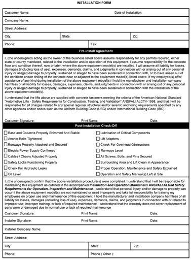
31 POST-INSTALLATION CHECK-OFF Columns properly shimmed and stable Anchor Bolts tightened Pivot / Sheave Pins properly attached Electric power supply confirmed Cables adjusted properly Safety Locks functioning properly Check for hydraulic leaks Oil level Lubrication of critical components Check for overhead obstructions All Screws, Bolts, and Pins securely fastened Surrounding area clean Operation, Maintenance and Safety Manuals on site. Perform an Operational Test with a typical vehicle ALOIM-2000, American National Standard for Automotive Lifts-Safety Requirements for Operation, Inspection and Maintenance. Shall display the lift manufacturer s operating instructions; ALI/SM 93-1, ALI Lifting It Right safety manual; ALI/ST-90 ALI Safety Tips card; ANSI/ALI AL- OIM-2000, American National Standard for Automotive Lifts-Safety Requirements for Operation, Inspection and Maintenance; and in the case of frame engaging lifts, ALI/ LP-GUIDE, Vehicle Lifting Points/Quick Reference Guide for Frame Engaging Lifts; in a conspicuous location in the lift area convenient to the operator. Shall provide necessary lockout/tagout means for energy sources per ANSI Z (R1993), Safety Requirements for the Lockout/Tagout of Energy Sources, before beginning any lift repairs. Shall not modify the lift in any manner without the prior written consent of the manufacturer. STEP 19 (Operation Instructions) OWNER/EMPLOYER RESPONSIBILITIES The Owner/Employer: Shall ensure that lift operators are qualified and that they are trained in the safe use and operation of the lift using the manufacturer s operating instructions; ALI/SM01-1, ALI Lifting it Right safety manual; ALI/ST-90 ALI Safety Tips card; ANSI/ALI ALOIM-2000, American National Standard for Automotive Lifts-Safety Requirements for Operation, Inspection and Maintenance; ALI/WL Series, ALI Uniform Warning Label Decals/Placards; and in the case of frame engaging lifts, ALI/LP-GUIDE, Vehicle Lifting Points/Quick Reference Guide for Frame Engaging Lifts. Shall establish procedures to periodically inspect the lift in accordance with the lift manufacturer s instructions or ANSI/ALI ALOIM-2000, American National Standard for Automotive Lifts-Safety Requirements for Operation, Inspection and Maintenance; and The Employer shall ensure that lift inspectors are qualified and that they are adequately trained in the inspection of the lift. Shall establish procedures to periodically maintain the lift in accordance with the lift manufacturer s instructions or ANSI/ALI ALOIM-2000, American National Standard for Automotive Lifts-Safety Requirements for Operation, Inspection and Maintenance; and The Employer shall ensure that lift maintenance personnel are qualified and that they are adequately trained in the maintenance of the lift. Shall maintain the periodic inspection and maintenance records recommended by the manufacturer or ANSI/ALI 31 STEP 20 (Lift Operation Safety) WARNING! TO AVOID PERSONAL INJURY AND/OR PROPERTY DAMAGE, PERMIT ONLY TRAINED PERSONNEL TO OPERATE LIFT. AFTER REVIEWING THESE INSTRUC- TIONS, PRACTICE USING LIFT CONTROLS BY RUNNING THE LIFT THROUGH A FEW UNLOADED CYCLES BEFORE LOADING VEHICLE ON LIFT. NEVER RAISE JUST ONE END, ONE CORNER, OR ONE SIDE OF VEHICLE.
32 inspect your lift. Never operate if it malfunctions or if it has broken or damaged parts. Use only qualified lift service personnel and genuine BendPak parts to make repairs. train all employees in use and care of lift, using manufacturer s instructions and Lifting It Right and Safety Tips supplied with the lift. allow unauthorized or untrained persons to position vehicle or operate lift. unauthorized persons from being in shop area while lift is in use. of the lift and surrounding area. Pay careful attention to overhead clearances. 4. Raise the lift to the desired height by pressing the push button on the power unit. NOTE: ALLOW (2) SECONDS BETWEEN MOTOR STARTS. FAILURE TO COMPLY MAY CAUSE MOTOR BURNOUT.. After vehicle is raised to the desired height, lower the lift onto the nearest Safety Lock. Do not allow Cables to become slack. ALWAYS ENSURE ALL SAFETY LOCKS ARE ENGAGED before entering work area. permit anyone on lift or inside vehicle when it is either being raised or lowered. keep area around lift free of tools, debris, grease and oil. overload lift. Capacity of lift is shown on nameplate affixed to the lift. stand in front of the vehicle while it is being positioned in lift bay. block open or override self-closing lift controls; they are designed to return to the Off or Neutral position when released. remain clear of lift when raising or lowering vehicles. DANGER! VISUALLY CONFIRM THAT ALL PRIMARY SAFETY LOCKS ARE ENGAGED BEFORE ENTERING WORK AREA. SUSPENSION COMPONENTS USED ON THIS LIFT ARE INTENDED TO RAISE AND LOWER LIFT ONLY AND ARE NOT MEANT TO BE LOAD HOLDING DEVICES. REMAIN CLEAR OF ELEVATED LIFT UNLESS VISUAL CONFIRMATION IS MADE THAT ALL PRIMARY SAFETY LOCKS ARE FULLY ENGAGED AND THE LIFT IS LOWERED ONTO THE SAFETY LOCKS, REFER TO INSTALLATION/ OPERATION MANUAL FOR PROPER SAFETY LOCK PROCEDURES AND/OR FURTHER INSTRUCTION. use safety stands when removing or installing heavy components. go under raised vehicle if safety locks are not engaged. NEVER LEAVE LIFT IN ELEVATED CONDITION unless all Safety Locks are engaged. excessive rocking of vehicle while on lift. if vehicle is in danger of falling. tool trays, stands, etc. before lowering lift. safety locks before attempting to lower lift. DO NOT position yourself between a wall and the lift. If the vehicle falls in that direction, you may be severely injured or killed. To Raise Lift; 1. Position vehicle tires in the center of each Runway. 2. Set parking brake and use Wheel Chocks to hold vehicle in position. 3. Before raising vehicle, be sure all personnel are clear 32
33 2. Check all Cable connections, bolts and pins to ensure proper mounting. WARNING! WHEN LOWERING THE LIFT PAY CAREFUL ATTEN- TION THAT ALL PERSONNEL AND OBJECTS ARE KEPT CLEAR. ALWAYS KEEP A VISUAL LINE OF SIGHT ON THE LIFT AT ALL TIMES. ALWAYS MAKE SURE THAT ALL LOCKS ARE DISENGAGED. IF ONE OF THE LOCKS INADVERTENTLY LOCKS UPON DESCENT THE VEHICLE MAY DISMOUNT CAUSING PERSONAL INJURY OR DEATH. To Lower Lift; 1. Before lowering vehicle, be sure all personnel are clear of the lift and surrounding area. Pay careful attention to overhead clearances. Ensure all tools and equipment have been cleared from under the lift. 2. Raise the lift off of the Safety Locks by pressing the push button on the Power Unit. Make sure you raise the lift by at least two inches to allow adequate clearance for the locks to clear. 3. Lubricate Safety Lock pivot points with general purpose oil or WD-40. MONTHLY MAINTENANCE 1. Check Safety Locks to ensure they are in good operating condition. Lubricate locking latch shafts. Push release arm several times for oil to penetrate pivot points. 2. Check equalizer cable tension. Adjust per lift installation instructions. 3. Check all Cables for excessive signs of wear. 4. Make a visual inspection of ALL MOVING PARTS and check for excessive signs of wear. problems develop. replace ALL FAULTY PARTS before lift is put back into operation. 3. Press the push button air safety valve and HOLD. 4. Push the LOWERING HANDLE on the Power Unit until the lift has descended completely. CAUTION! IF YOU ARE NOT COMPLETELY FAMILIAR WITH AUTO- MOTIVE LIFT MAINTENANCE PROCEDURES; STOP AND CONTACT THE MANUFACTURER FOR INSTRUC- TIONS. TO AVOID PERSONAL INJURY, PERMIT ONLY QUALIFIED PERSONNEL TO PERFORM MAINTE- NANCE ON THIS EQUIPMENT. should be torqued to 90 ft/lbs. refill if required per lift installation instructions. on the lift if unable to read or missing. Reorder labels from BendPak. inspection checklist and maintenance log sheet. DAILY MAINTENANCE 1. Make a visual inspection of ALL MOVING PARTS and check for excessive signs of wear. 2. Check safety locks to ensure they are in good operating condition. 3. Check cables and sheaves for wear. Replace worn parts as required with genuine BendPak parts. 4. Inspect adapters for damage or excessive wear. Replace as required with genuine BendPak parts. WEEKLY MAINTENANCE 1. Lubricate all Sheave and rollers with general purpose oil. 33
34 WIRE ROPE INSPECTION AND MAINTENANCE Lifting cables should be replaced every three - five years or when visible signs of damage are apparent. DO NOT USE LIFT WITH DEFECTIVE / WORN CABLES. Lifting cables should be maintained in a well-lubricated condition at all times. Wire rope is only fully protected when each wire strand is lubricated both internal and external. Excessive wear will shorten the life of the wire rope. The factory suggested wire rope lubricant that penetrates to the core of the rope and provides long-term lubrication between each individual strand is 90-WT gear oil or ALMASOL Wire Rope Lubricant. In order to make sure that the inner layers of the rope remain well lubricated, lubrication should be carried out at intervals not exceeding three months during operation. All sheaves and guide rollers in contact with the moving rope should be given regular visual checks for surface wear and lubricated to make sure that they run freely. This operation should be carried out at appropriate intervals generally not exceeding three months during operation. For all sheave axles, the factory recommends standard wheel bearing grease. For all sheaves and/or guide rollers, the factory recommends 90-WT gear oil or similar heavy lubricant applied by any method including pump / spray dispensing, brush, hand and/or swabbing.. HOW OFTEN TO INSPECT Lifting cables should be visually inspected at least once each day when in use, as suggested by American Petroleum Institute (API) RP4 guidelines. Any lifting cables that have met the criteria for removal must be immediately replaced. WHEN TO REPLACE LIFTING CABLES DUE TO BROKEN WIRES Lifting cables should be removed from service when you see six randomly distributed broken wires within any one lay length, or three broken wires in one strand within one lay length. OTHER REASONS TO REPLACE LIFTING CABLES Corrosion that pits the wires and/or connectors. Evidence of kinking, crushing, cutting, bird-caging or a popped core. Wear that exceeds 10% of a wire s original diameter. Evidence of heat damage. HOW TO FIND BROKEN WIRES The first step is to relax your rope to a stationary position and move the pick-up points off the sheaves. Clean the surface of the rope with a cloth a wire brush, if necessary so you can see any breaks. Flex the rope to expose any broken wires hidden in the valleys between the strands. Visually check for any broken wires. One way to check for crown breaks is to run a cloth along the rope to check for possible snags. With an awl, probe between wires and strands and lift any wires that appear loose. Evidence of internal broken wires may require a more extensive rope examination. 34
35 3
36 36
37 Safe Lift Operation Automotive and truck lifts are critical to the operation and profitability of your business. The safe use of this and other lifts in your shop is critical in preventing employee injuries and damage to customer s vehicles. By operating lifts safely you can ensure that your shop is profitable, productive and safe. Safe operation of automotive lifts requires that only trained employees should be allowed to use the lift. TRAINING SHOULD INCLUDE, BUT NOT LIMITED TO: Proper positioning of the vehicle on the runway. (See manufacturers minimize wheel base loading requirements.) Use of the operating controls. Understanding the lift capacity. Proper use of jack stands or other load supporting devices. Proper use, understanding and visual identification of safety lock devices and their operation. Reviewing the safety rules. Proper housekeeping procedures (lift area should be free of grease, oil, tools, equipment, trash, and other debris) A daily inspection of the lift should be completed prior to its use. Safety devices, operating controls, lift arms and other critical parts should be inspected prior to using the lift. All maintenance and repairs of the lift should be completed by following the manufacturer s requirements. Lift repair parts should meet or exceed OEM specifications. Repairs should only be completed by a qualified lift technician. The vehicle manufacturer s recommendations should be used for spotting and lifting the vehicle. LIFT OPERATION SAFETY It is important that you know the load limit. Be careful that you do not overload the lift. If you are unsure what the load limit is, check the data plate found on one of the lift columns or contact the manufacturer. The center of gravity should be followed closely to what the manufacturer recommends. Always make sure you have proper overhead clearance. Additionally, check that attachments, (vehicle signs, campers, antennas, etc.) are not in the way. Be sure that prior to the vehicle being raised, the doors, trunk, and hood are closed securely Prior to being raised, make sure there is no one standing closer than six feet from the lift After positioning the vehicle on the lift runways, set the emergency brake, make sure the ignition is off, the doors are closed, overhead obstructions are cleared, and the transmission is in neutral. Double check that the automatic chock devices are in position and then when the lift is raised, observe the chocks Put pads or adapters in the right position under the contact points that have been recommended The lift should be raised just until the vehicle s wheels are about one foot off the ground. If contact with the vehicle is uneven or it appears that the vehicle is not sitting secure, carefully lower the lift and readjust. Always consider potential problems that might cause a vehicle to slip, i.e., heavy cargo, undercoating, etc. Pay attention when walking under a vehicle that is up on the hydraulic lift. 37
38 DO NOT leave the controls while the lift is still in motion. DO NOT stand directly in front of the vehicle or in the bay when vehicle is being loaded or driven into position. DO NOT Go near vehicle or attempt to work on the vehicle when being raised or lowered. REMAIN CLEAR of lift when raising or lowering vehicle. DO NOT rock the vehicle while on the lift or remove any heavy component from vehicle that may cause excessive weight shift. DO NOT lower the vehicle until people, materials, and tools are clear ALWAYS ENSURE that the safeties are engaged and lowered on to the safety ladders before any attempt is made to work on or near vehicle. Some vehicle maintenance and repair activities may cause the vehicle to shift. Follow the manufacturer s guidelines when performing these operations. The use of jack stands or alternate lift points may be required when completing some repairs. READ AND UNDERSTAND all safety warning procedures before operating lift. KEEP HANDS AND FEET CLEAR. Remove hands and feet from any moving parts. Keep feet clear of lift when lowering. Avoid pinch points. ONLY TRAINED OPERATORS should operate this lift. All non-trained personnel should be kept away from work area. Never let non-trained personnel come in contact with, or operate lift. USE LIFT CORRECTLY. Use lift in the proper manner. Never use lifting adapters other than what is approved by the manufacturer. DO NOT override self-closing lift controls. CLEAR AREA if vehicle is on danger of falling. STAY ALERT. Watch what you are doing. Use common sense. Be aware. CHECK FOR DAMAGED PARTS. Check for alignment of moving parts, breakage of parts or any condition that may affect its operation. Do not use lift if any component is broken or damaged. NEVER remove safety related components from the lift. Do not use lift if safety related components are damaged or missing. When the lift is being lowered, make sure everyone is standing at least six feet away. Be sure there are no jacks, tools, equipment, left under the lift before lowering. Always lower the vehicle down slowly and smoothly. 38
39 LIFT WILL NOT RAISE POSSIBLE CAUSE 1. Air in oil, (1,2,8,13) 2. Cylinder binding, (9) 3. Cylinder leaks internally, (9) 4. Motor run backward under pressure, (11). Lowering valve leaks, (3,4,6,10,11) 6. Motor runs backwards, (7,14,11) 7. Pump damaged, (10,11) 8. Pump won t prime, (1,8,13,14,3,12,10,11) 9. Relief valve leaks, (10,11) 10. Voltage to motor incorrect, (7,14,11) REMEDY INSTRUCTION 1. Check for proper oil level The oil level should be up to the bleed screw in the reservoir with the lift all the way down. 2. Bleed cylinders See Installation Manual 3. Flush- Release valve to get rid of Hold release handle down and start unit allowing possible contamination it to run for 1 seconds. 4. Dirty oil Replace oil with clean Dexron ATF.. Tighten all fasteners Tighten fasteners to recommended torques. 6. Check for free movement of release If handle does not move freely, replace bracket or handle assembly. 7. Check motor is wired correctly Compare wiring of motor to electrical diagram on drawing. 8. Oil seal damaged or cocked Replace oil seal around pump shaft. 9. See Installation Manual Consult Lift Manufacturer. 10. Replace with new part Replace with new part. 11. Return unit for repair Return unit for repair. 12. Check pump-mounting bolts Bolts should be 1 to 18 ft. lbs. 13. Inlet screen clogged Clean inlet screen or replace. 14. Check wall outlet voltages and wiring Make sure unit and wall outlet are wired properly. 39
40 MOTOR WILL NOT RUN POSSIBLE CAUSE 1. Fuse blown, (,2,1,3,4) 2. Limit switch burned out, (1,2,3,4) 3. Microswitch burned out, (1,2,3,4) 4. Motor burned out, (1,2,3,4,6). Voltage to motor incorrect, (2,1,8) REMEDY INSTRUCTION 1. Check for correct voltage Compare supply voltage with voltage on motor name tag. Check that the wire is sized correctly. N.E.C. table requires AWG 10 for 2 Amps. 2. Check motor is wired correctly Compare wiring of motor to electrical diagram on drawing. 3. Don t use extension cords According to N.E.C. : The size of the conductors should be such that the voltage drop would not exceed 3% to the farthest outlet for power Do not run motor at 11 VAC damage to the motor will occur. 4. Replace with new part Replace with new part.. Reset circuit breaker/fuse Reset circuit breaker/fuse. 6. Return unit for repair Return unit for repair. 7. See Installation Manual See Installation Manual. 8. Check wall outlet voltage and wiring Make sure unit and wall outlet is wired properly. Motor must run at 208/230 VAC. LIFT LOWERS SLOWLY OR NOT AT ALL POSSIBLE CAUSE 1. Cylinders binding, (1) 2. Release valve clogged, (,4,2,3) 3. Pressure fitting too long, (6) REMEDY INSTRUCTION 1. See Installation Manual Consult Lift Manufacturer. 2. Replace with new part Replace with new part. 3. Return for repair Return for repair. 4. Check oil Use clean 10-WT hydraulic oil or Dexron-III automatic transmission fluid only. If ATF is contaminated, replace with clean ATF and clean entire system.. Clean release valve Wash release valve in solvent and blow out with air. 6. Replace fitting with short thread lead Replace fitting with short thread lead. 40
41 WILL NOT RAISE LOADED LIFT POSSIBLE CAUSE 1. Air in oil, (1,2,3,4) 2. Cylinder binding, () 3. Cylinder leaks internally, () 4. Lift overloaded, (6,). Lowering valve leaks, (7,8,1,,9) 6. Motor runs backwards, (10,12,9) 7. Pump damaged, (,9) 8. Pump won t prime, (1,2,3,4,,11,9) 9. Relief valve leaks, (8,,9) 10. Voltage to motor incorrect, (10,12,) REMEDY INSTRUCTION 1. Check oil level The oil level should be up to the bleed screw in the reservoir [with the lift all the way down. 2. Check/Tighten inlet tubes Replace inlet hose assembly. 3. Oil seal damaged or cocked Replace oil seal and install. 4. Bleed cylinders See Installation Manual.. See Installation Manual Consult Lift Manufacturer. 6. Check vehicle weight Compare weight of vehicle to weight limit of the lift. 7. Flush release valve Hold release handle down and start unit allowing it to run for 1 seconds. 8. Replace with new part Replace with new part. 9. Return unit for repair Return unit for repair. 10. Check motor is wired correctly Compare wiring of motor to electrical diagram on power unit drawing. 11. Inlet screen clogged Clean inlet screen or replace. 12. Check wall outlet voltage and wiring Make sure unit and wall outlet is wired properly. IMPORTANT If vehicle becomes stranded in the air, follow all operation instructions as shown on pages 33 and 40. If after observing that all mechanical locks are released and the lift still fails move following all standard operating procedures, immediately stop using the lift and contact factory or factory approved service center for further instructions. 41
42 LIFT WILL NOT STAY UP POSSIBLE CAUSE 1. Air in oil, (1,2,3) 2. Check valve leaks, (6) 3. Cylinders leak internally, (7) 4. Lowering valve leaks, (4,,1,7,6). Leaking fittings, (8) REMEDY INSTRUCTION 1. Check oil level The oil level should be up to the bleed screw in the reservoir with the lift all the way down. 2. Oil seal damaged and cocked Replace oil seal around pump shaft. 3. Bleed cylinder Refer to Installation Manual. 4. Flush release valve Hold release handle down and start unit allowing it to run for 1 seconds.. Replace with new valve Replace with new valve. 6. Return unit for repair Return unit for repair. 7. See Installation Manual Consult Lift Manufacturer. 8. Check complete hydraulic system for leaks tighten all hydraulics fittings and inspects all hoses. 42
 Bolt Size (Metric) SAE 0-1-2 SAE Grade SAE Grade 8 SOCKET HEAD CAP SCREW CLASS 4.8 CLASS 8.8 CLASS 10.9 CLASS 12.9 1/4-20 M6 x 1.")

43 Grease Port / Lubrication Locations Lubricate Once A Week Torque Recommendations VALUES ARE STATED IN FOOT POUNDS (ft-lb) Bolt Size (SAE) Bolt Size (Metric) SAE SAE Grade SAE Grade 8 SOCKET HEAD CAP SCREW CLASS 4.8 CLASS 8.8 CLASS 10.9 CLASS /4-20 M6 x /16-18 M8 x /8-16 M10 x / /2-13 M12 x /16-12 M14 x /8-11 M16 x /4-10 M18 x /8-9 M22 x /4 Anchor Bolts 7 MIN 110 MAX 43
44 MAINTENANCE RECORDS 44
45 4
46 4 REVISION REV DESCRIPTIO N DAT E E DITED B Y ECO # A PRODUCTION RELEASE, DERIVED FROM /03/201 3 TM DETAIL A SCALE 1 : ITEM NO. DO NOT PART NUMBER SCALE DIMENSIONS DRAWING ARE IN MM CHECKED N AME DAT E DESCRIPTION QT Y RE V H D-9/9XL/XW CROSSTUBE ASSEMBLY, SMALL WINDO W 1 A H D-9/9XL/XW CROSSTUBE ASSEMBLY, LARGE WINDO W 1 A H D-700BL/9 SERIES OFF SIDE POST WELDMEN T 3 A H D-700BL/9 SERIES POST POWER SIDE WELDMEN T 1 A H D-700BL/9/9ST/9AE SAFETY LADDER WELDMEN T 4 C H D-700BL/9/9ST/9SW POWER SIDE RAMP ASSEMBL Y 1 M H D-700BL/9/9ST/9SW OFF SIDE RAMP WELDMEN T 1 E H D-7/700/9 SERIES TIRE STOP PLATE WELDMEN T 2 E H D-700BL/BLX, 9/ST/STX/XW DRIVE UP RAMP ASSEMBL Y 2 E N UT M16 x N UT M16 x 2 N L W ASHER M16 x 30mm FLA T 4 - D RAWN TM 0/03/ LEMONWOOD DR. SANTA PAULA, CA MATERIAL: N OTE: UNLESS OTHERWISE SPECIFIED. --- SIZE: 1. SEE SHIPPING INSTRUCTIONS FOR FINAL PACKAGING ASSEMBLY THREAD M16 HARDWARE ONTO LADDER BOLTS AS SHOWN NEXT THIRD ANGLE PROJECTION TITLE: SIZE A DWG. HD-9 LIFT SUPERSTRUCTURE PROPRIETARY AND CONFIDENTIAL INFORMATION CONTAINED IN THIS DRAWING THE IS T HE SOLE PROPERTY OF BENDPAK INC. ANY WHOLE WITHOUT REPRODUCTION IN PART OR AS A S CALE: 1:4 0 SHEET 1 OF 1 P ROHIBITED. T HE WRITTEN PERMISSION OF BENDPAK INC. IS NO REV A 46
47 DETAIL A SCALE 1 : 8 B DETAIL SCALE 1 : B N AME E NOTE: UNLESS OTHERWISE SPECIFIED SEE SHIPPING INSTRUCTIONS FOR FINAL PACKAGING INSERT PARTS BAG INTO PARTS BOX FOR SHIPMENT THREAD 338 WITH 4342 ONTO CABLES FOR SHIPMENT HOSES AND CABLES IN REPRESENTATIONAL FORM (*) LENGTH FOR REFERENCE ONLY ALL LABELS TO BE APPLIED TO POSTS AFTER PAINTING. SEE RECEIVED LIFT FOR PLACEMENT TO BE ADDED BY REQUEST ONLY NEXT ASSEMBLY REVISION REV DESCRIPTIO N DAT E E DITED B Y ECO # A PRODUCTION RELESAE,DERIVED FROM /07/201 3 TM ITEM NO. DO NOT PART NUMBER SCALE DRAWING DIMENSIONS ARE IN MM CHECKED DAT D RAWN TM 0/07/ LEMONWOOD DR. SANTA PAULA, CA THIRD ANGLE PROJECTION D ESCRIPTION QTY. RE V 1 2 G N H D-7/9 SERIES PARTS BA 1 D H D-7/700/9 SERIES DRIVE UP RAMP PI 4 B F LEX TUBE ASSEMBLY 1320m m 1 B P OWER UNIT VIBRATION DAMPENE R 1 B P USH BUTTON AIR ASSEMBL Y 1 D H D-9 CABLE ASSEMBLY Ø10 x 298mm S T 1 A H D-9/9A CABLE ASSEMBLY Ø10 x 478mm S T 1 E H D-7PXN/9 CABLE ASSEMBLY Ø10 x 7081mm S T H D-9/9A CABLE ASSEMBLY Ø10 x 8693mm S T 1 E W HEEL CHOC K 2 A N UT M18 x 2. N L 4 A 1/4" POLY-FLO TUBIN G 17000*m m - H D-SERIES FLEX TUBE BRACKET PLAT E 1 F H D-SERIES FLEX TUBE ANGL E 1 E W ASHER M18 FLA T H DS SERIES FOOT PLAT E 4 A HD-14/14SS/14X HD-9/9A/9N/9/PL/9ST/9AE HYDRAULIC HOSE ASSEMBLY Ø6.4 x 3380mm 1 F AB 3/4" x 4-3/4 " 16 A H D-7P/700/9 SERIES TOP PLATE WELDMEN T 4 C H D-9 INSTALLATION MANUA L S AFETY MANUAL ALI / SM B ENDPAK #90 WARRANTY CAR D ALIGN OIM OPERATION INSPECTION & MAINTENANCE S AFETY TIPS CARD ALI-ST POST SERIAL TA G P RODUCT DATA LABE L M AX CAP DANGER 9 K W ARNING ALI/WL A LI SAFETY INSTRUCTIONS STICKE R M ANUFACTURER LABE L POST DECAL KIT, LESS AL I 1 A TITLE: PARTS BOX HD-9 MATERIAL: SIZE: SIZE A DWG. NO PROPRIETARY AND CONFIDENTIAL INFORMATION CONTAINED IN THIS DRAWING THE IS T HE SOLE PROPERTY OF BENDPAK INC. ANY WHOLE WITHOUT REPRODUCTION IN PART OR AS A 1:2 P ROHIBITED. T HE WRITTEN PERMISSION OF BENDPAK INC. IS REV A S CALE: SHEET 1 OF 1 47
48 11 3 REVISION REV DESCRIPTIO N DAT E E DITED B Y ECO # A PRODUCTION RELEASE, DERIVED FROM /02/201 3 TM DETAIL A SCALE 1 : ITEM NO. DO NOT PART NUMBER SCALE DIMENSIONS DRAWING ARE IN MM CHECKED N AME DAT E D ESCRIPTION QTY. RE V H D-9ST/STX CROSSTUBE ASSEMBLY, SMALL WINDO W 1 A H D-9ST/STX CROSSTUBE ASSEMBLY, LARGE WINDO W 1 A H D-700BL/9 SERIES POST POWER SIDE WELDMEN T 1 A H D-700BL/9 SERIES OFF SIDE POST WELDMEN T 3 A H D-700BL/9/9ST/9AE SAFETY LADDER WELDMEN T 4 C H D-700BL/9/9ST/9SW POWER SIDE RAMP ASSEMBL Y 1 M H D-700BL/9/9ST/9SW OFF SIDE RAMP WELDMEN T 1 E H D-7/700/9 SERIES TIRE STOP PLATE WELDMEN T 2 E H D-700BL/BLX, 9/ST/STX/XW DRIVE UP RAMP ASSEMBL Y 2 E N UT M16 x N UT M16 x 2 N L W ASHER M16 x 30mm FLA T 4 - D RAWN TM 0/02/ LEMONWOOD DR. SANTA PAULA, CA MATERIAL: N OTE: UNLESS OTHERWISE SPECIFIED. --- SIZE: 1. SEE SHIPPING INSTRUCTIONS FOR FINAL PACKAGING ASSEMBLY THREAD M16 HARDWARE ONTO LADDER BOLTS AS SHOWN NEXT THIRD ANGLE PROJECTION TITLE: SIZE A DWG. HD-9ST LIFT SUPERSTRUCTURE PROPRIETARY AND CONFIDENTIAL INFORMATION CONTAINED IN THIS DRAWING THE IS T HE SOLE PROPERTY OF BENDPAK INC. ANY WHOLE WITHOUT REPRODUCTION IN PART OR AS A S CALE: 1:4 0 SHEET 1 OF 1 P ROHIBITED. HE WRITTEN PERMISSION OF BENDPAK INC. IS NO REV A T 48
49 DETAIL A SCALE 1 : NOTE: UNLESS OTHERWISE SPECIFIED SEE SHIPPING INSTRUCTIONS FOR FINAL PACKAGING INSERT PARTS BAG INTO PARTS BOX FOR SHIPMENT THREAD 338 WITH 4342 ONTO CABLES FOR SHIPMENT HOSES AND CABLES IN REPRESENTATIONAL FORM (*) LENGTH FOR REFERENCE ONLY ALL LABELS TO BE APPLIED TO POSTS AFTER PAINTING. SEE RECEIVED LIFT FOR PLACEMENT TO BE ADDED BY REQUEST ONLY NEXT ASSEMBLY REVISION REV DESCRIPTIO N DAT E E DITED B Y ECO # A PRODUCTION RELEASE, DERIVED FROM /09/201 3 TM ITEM NO. DO NOT PART NUMBER 7401 SCALE DRAWING DIMENSIONS ARE IN MM CHECKED N AME DAT E D RAWN TM 0/09/ LEMONWOOD DR. SANTA PAULA, CA THIRD ANGLE PROJECTION D ESCRIPTION QTY. RE V 1 4 H D-7/700/9 SERIES DRIVE UP RAMP PI N 4 B P USH BUTTON AIR ASSEMBL Y 1 D P OWER UNIT VIBRATION DAMPENE R 1 B F LEX TUBE ASSEMBLY 1170m m 1 B H D-9ST CABLE ASSEMBLY Ø10 x 2926mm S T 1 F H D-9ST CABLE ASSEMBLY Ø10 x 436mm S T 1 F H D-9ST CABLE ASSEMBLY Ø10 x 7048mm S T 1 F H D-9ST CABLE ASSEMBLY Ø10 x 8476mm S T 1 F N UT M18 x 2. N L W HEEL CHOC K 2 A H D-7/9 SERIES PARTS BA G 1 D /4" POLY-FLO TUBIN G 17000*m m H D-SERIES FLEX TUBE BRACKET PLAT E 1 F H D-SERIES FLEX TUBE ANGL E 1 E W ASHER M18 FLA T H DS SERIES FOOT PLAT E 4 A HD-14/14SS/14X HD-9/9A/9N/9/PL/9ST/9AE HYDRAULIC HOSE ASSEMBLY Ø6.4 x 3380mm 1 F AB 3/4" x 4-3/4 " H D-7P/700/9 SERIES TOP PLATE WELDMEN T 4 C H D-9 INSTALLATION MANUA L 1 A S AFETY MANUAL ALI / SM B ENDPAK #90 WARRANTY CAR D ALIGN OIM OPERATION INSPECTION & MAINTENANCE S AFETY TIPS CARD ALI-ST M ANUFACTURER LABE L POST SERIAL TA G P RODUCT DATA LABE L M AX CAP DANGER 9 K W ARNING ALI/WL 20 0 A LI SAFETY INSTRUCTIONS STICKE R 4 POST DECAL KIT, LESS AL I 1 A TITLE: PARTS BOX HD-9ST MATERIAL: SIZE: SIZE A DWG. NO PROPRIETARY AND CONFIDENTIAL INFORMATION CONTAINED IN THIS DRAWING THE IS T HE SOLE PROPERTY OF BENDPAK INC. ANY WHOLE WITHOUT REPRODUCTION IN PART OR AS A 1:2 P ROHIBITED. HE WRITTEN PERMISSION OF BENDPAK INC. IS REV A S CALE: SHEET 1 OF 1 T 49
50 REVISION REV DESCRIPTIO N DAT E E DITED B Y ECO # A PRODUCTION RELEASE, DERIVED FROM /02/201 3 TM DETAIL A SCALE 1 : DIMENSIONS 3 MATERIAL: N OTE: UNLESS OTHERWISE SPECIFIED. --- SIZE: 1. SEE SHIPPING INSTRUCTIONS FOR FINAL PACKAGING NEXT ASSEMBLY THREAD M16 HARDWARE ONTO LADDER BOLTS AS SHOWN ITEM NO. DO NOT PART NUMBER SCALE DRAWING ARE IN MM CHECKED N AME DAT E D RAWN TM 0/02/ LEMONWOOD DR. SANTA PAULA, CA THIRD ANGLE PROJECTION DESCRIPTION QT Y RE V H D-9ST/STX CROSSTUBE ASSEMBLY, SMALL WINDO W 1 A H D-9ST/STX CROSSTUBE ASSEMBLY, LARGE WINDO W 1 A H D-7P/700BLX/9STX/9XW SAFETY LADDER WELDMEN T 4 C H D-7P/700BLX/9STX/9XW/14T POWER POST WELDMEN T 1 A H D-7P/700BLX/9STX/9XW/14T OFF SIDE POST WELDMEN T 3 A HD-700BLX/9STX/9SWX/9XW POWER SIDE RAMP ASSEMBLY 1 Q HD-700BLX/9STX/ 9SWX/9XL/9XW OFFSIDE RAMP WELDMENT 1 G H D-7/700/9 SERIES TIRE STOP PLATE WELDMEN T 2 E H D-700BL/BLX, 9/ST/STX/XW DRIVE UP RAMP ASSEMBL Y 2 E N UT M16 x N UT M16 x 2 N L W ASHER M16 x 30mm FLA T 4 - TITLE: SIZE A DWG. HD-9STX LIFT SUPERSTRUCTURE NO PROPRIETARY AND CONFIDENTIAL INFORMATION CONTAINED IN THIS DRAWING THE IS T HE SOLE PROPERTY OF BENDPAK INC. ANY WHOLE WITHOUT REPRODUCTION IN PART OR AS A 1:4 0 P ROHIBITED. T HE WRITTEN PERMISSION OF BENDPAK INC. IS REV A S CALE: SHEET 1 OF 1 0
51 11 DETAIL A SCALE 1 : B NOTE: UNLESS OTHERWISE SPECIFIED SEE SHIPPING INSTRUCTIONS FOR FINAL PACKAGING INSERT PARTS BAG INTO PARTS BOX FOR SHIPMENT THREAD 338 WITH 4342 ONTO CABLES FOR SHIPMENT HOSES AND CABLES IN REPRESENTATIONAL FORM (*) LENGTH FOR REFERENCE ONLY ALL LABELS TO BE APPLIED TO POSTS AFTER PAINTING. SEE RECEIVED LIFT FOR PLACEMENT TO BE ADDED BY REQUEST ONLY DETAIL B SCALE 1 : 12 NEXT ASSEMBLY REVISION REV DESCRIPTIO N DAT E E DITED B Y ECO # A PRODUCTION RELEASE, DERIVED FROM /09/201 3 TM ITEM NO. DO NOT PART NUMBER SCALE DRAWING DIMENSIONS ARE IN MM CHECKED N AME DAT E D RAWN TM 0/09/ LEMONWOOD DR. SANTA PAULA, CA THIRD ANGLE PROJECTION D ESCRIPTION QTY. RE V P OWER UNIT VIBRATION DAMPENE R 1 B N UT M18 x 2. N L HD-9STX/XP/XPR-10ACX CABLE ASSEMBLY Ø10 x 9404mm ST 1 D H D-9STX CABLE ASSEMBLY Ø10 x 7978mm S T 1 E H D-9STX CABLE ASSEMBLY Ø10 x 4663mm S T 1 E H D-9STX CABLE ASSEMBLY Ø10 x 3240mm S T 1 F W HEEL CHOC K 2 A F LEX TUBE ASSEMBLY 1170m m 1 B P USH BUTTON AIR ASSEMBL Y 1 D H D-7/700/9 SERIES DRIVE UP RAMP PI N 4 B H D-7/9 SERIES PARTS BA G 1 D /4" POLY-FLO TUBIN G 17000*m m H D-SERIES FLEX TUBE BRACKET PLAT E 1 F H D-SERIES FLEX TUBE ANGL E 1 E W ASHER M18 FLA T H DS SERIES FOOT PLAT E 4 A H D-9STX/9XW HYD. HOSE ASSY Ø6.4 x 3683m m 1 D AB 3/4" x 4-3/4 " H D-7P/700/9 SERIES TOP PLATE WELDMEN T 4 C H D-9 INSTALLATION MANUA L S AFETY MANUAL ALI / SM B ENDPAK #90 WARRANTY CAR D ALIGN OIM OPERATION INSPECTION & MAINTENANCE S AFETY TIPS CARD ALI-ST M ANUFACTURER LABE L POST SERIAL TA G P RODUCT DATA LABE L M AX CAP DANGER 9 K W ARNING ALI/WL 20 0 A LI SAFETY INSTRUCTIONS STICKE R 4 POST DECAL KIT, LESS AL I 1 A TITLE: PARTS BOX HD-9STX MATERIAL: SIZE: SIZE A DWG. NO PROPRIETARY AND CONFIDENTIAL INFORMATION CONTAINED IN THIS DRAWING THE IS T HE SOLE PROPERTY OF BENDPAK INC. ANY WHOLE WITHOUT REPRODUCTION IN PART OR AS A 1:2 P ROHIBITED. HE WRITTEN PERMISSION OF BENDPAK INC. IS REV A S CALE: SHEET 1 OF 1 T 1
52 REVISION REV D ESCRIPTIO N DAT E E DITED B Y ECO # A PRODUCTION RELEASE, DERIVED FROM /03/201 3 TM DETAIL A 4 SCALE 1 : ITEM NO DO NOT PART NUMBER DESCRIPTION QTY RE V H D-9/9XL/XW CROSSTUBE ASSEMBLY, SMALL WINDO W 1 A H D-9/9XL/XW CROSSTUBE ASSEMBLY, LARGE WINDO W 1 A H D-7P/700BLX/9STX/9XW/14T POWER POST WELDMEN T 1 A H D-7P/700BLX/9STX/9XW/14T OFF SIDE POST WELDMEN T 3 A H D-7P/700BLX/9STX/9XW SAFETY LADDER WELDMEN T 4 C H D-700BLX/9STX/9SWX/9XW POWER SIDE RAMP ASSEMBL Y 1 Q HD-700BLX/9STX/ 9SWX/9XL/9XW OFFSIDE RAMP WELDMENT 1 G H D-7/700/9 SERIES TIRE STOP PLATE WELDMEN T 2 E H D-700BL/BLX, 9/ST/STX/XW DRIVE UP RAMP ASSEMBL Y 2 E N UT M16 x N UT M16 x 2 N L W ASHER M16 x 30mm FLA T 4 - SCALE DRAWING DIMENSIONS ARE IN MM CHECKED N AME DAT E D RAWN TM 0/03/ LEMONWOOD DR. SANTA PAULA, CA MATERIAL: N OTE: UNLESS OTHERWISE SPECIFIED SEE SHIPPING INSTRUCTIONS FOR FINAL PACKAGING THREAD M16 HARDWARE ONTO LADDER BOLTS AS SHOWN NEXT ASSEMBLY SIZE: THIRD ANGLE PROJECTION TITLE: SIZE A DWG. HD-9XW LIFT SUPERSTRUCTURE NO PROPRIETARY AND CONFIDENTIAL INFORMATION CONTAINED IN THIS DRAWING THE IS T HE SOLE PROPERTY OF BENDPAK INC. ANY WHOLE WITHOUT REPRODUCTION IN PART OR AS A 1:4 0 P ROHIBITED. HE WRITTEN PERMISSION OF BENDPAK INC. IS REV A S CALE: SHEET 1 OF 1 T 2
53 11 9 DETAIL A 8 SCALE 1 : 8 B NOTE: UNLESS OTHERWISE SPECIFIED. DETAIL B 28 SCALE 1 : 12 SEE SHIPPING INSTRUCTIONS FOR FINAL PACKAGING INSERT PARTS BAG INTO PARTS BOX FOR SHIPMENT THREAD 338 WITH 4342 ONTO CABLES FOR SHIPMENT HOSES AND CABLES IN REPRESENTATIONAL FORM (*) LENGTH FOR REFERENCE ONLY ALL LABELS TO BE APPLIED TO POSTS AFTER PAINTING. SEE RECEIVED LIFT FOR PLACEMENT TO BE ADDED BY REQUEST ONLY NEXT ASSEMBLY REVISION REV DESCRIPTIO N DAT E E DITED B Y ECO # A PRODUCTION RELEASE, DERIVED FROM /07/201 3 TM ITEM NO. DO NOT PART NUMBER SCALE DRAWING DIMENSIONS ARE IN MM CHECKED N AME DAT E D RAWN TM 0/07/ LEMONWOOD DR. SANTA PAULA, CA THIRD ANGLE PROJECTION D ESCRIPTION QTY. RE V N UT M18 x 2. N L 4 - W HEEL CHOC K 2 A F LEX TUBE ASSEMBLY 1320m m 1 B H D-9XW CABLE ASSEMBLY Ø10 x 9613mm S T 1 E H D-9XW CABLE ASSEMBLY Ø10 x 8007mm S T 1 A H D-9XW CABLE ASSEMBLY Ø10 x 4883mm S T 1 D H D-9XW CABLE ASSEMBLY Ø10 x 3263mm S T 1 A P USH BUTTON AIR ASSEMBL Y 1 D P OWER UNIT VIBRATION DAMPENE R 1 B H D-7/700/9 SERIES DRIVE UP RAMP PI N 4 B H D-7/9 SERIES PARTS BA G 1 D /4" POLY-FLO TUBIN G 17000*m m H D-SERIES FLEX TUBE BRACKET PLAT E 1 F H D-SERIES FLEX TUBE ANGL E 1 E W ASHER M18 FLA T H DS SERIES FOOT PLAT E 4 A H D-9STX/9XW HYD. HOSE ASSY Ø6.4 x 3683m m 1 D AB 3/4" x 4-3/4 " H D-7P/700/9 SERIES TOP PLATE WELDMEN T 4 C H D-9 INSTALLATION MANUA L S AFETY MANUAL ALI / SM B ENDPAK #90 WARRANTY CAR D ALIGN OIM OPERATION INSPECTION & MAINTENANCE S AFETY TIPS CARD ALI-ST POST SERIAL TA G P RODUCT DATA LABE L M AX CAP DANGER 9 K W ARNING ALI/WL 20 0 A LI SAFETY INSTRUCTIONS STICKE R 4 POST DECAL KIT, LESS AL I M ANUFACTURER LABE L TITLE: PARTS BOX HD-9XW MATERIAL: SIZE: SIZE A DWG. NO PROPRIETARY AND CONFIDENTIAL INFORMATION CONTAINED IN THIS DRAWING THE IS T HE SOLE PROPERTY OF BENDPAK INC. ANY WHOLE WITHOUT REPRODUCTION IN PART OR AS A 1:2 P ROHIBITED. HE WRITTEN PERMISSION OF BENDPAK INC. IS REV A S CALE: SHEET 1 OF 1 T 3
54 11 3 REVISION REV DESCRIPTIO N DAT E E DITED B Y ECO # A PRODUCTION RELEASE, DERIVED FROM /03/201 3 TM DETAIL A SCALE 1 : ITEM NO. DO NOT PART NUMBER SCALE DRAWING DIMENSIONS ARE IN MM CHECKED N AME DAT E DESCRIPTION QT Y RE V H D-9/9XL/XW CROSSTUBE ASSEMBLY, SMALL WINDO W 1 A H D-9/9XL/XW CROSSTUBE ASSEMBLY, LARGE WINDO W 1 A H D-700BL/9 SERIES POST POWER SIDE WELDMEN T 1 A H D-700BL/9 SERIES OFF SIDE POST WELDMEN T 3 A H D-700BL/9/9ST/9AE SAFETY LADDER WELDMEN T 4 C H D-9XL POWER SIDE RAMP ASSEMBL Y 1 E HD-700BLX/9STX/ 9SWX/9XL/9XW OFFSIDE RAMP WELDMENT 1 G H D-7/700/9 SERIES TIRE STOP PLATE WELDMEN T 2 E H D-700BL/BLX, 9/ST/STX/XW DRIVE UP RAMP ASSEMBL Y 2 E N UT M16 x N UT M16 x 2 N L W ASHER M16 x 30mm FLA T 4 - D RAWN TM 0/03/ LEMONWOOD DR. SANTA PAULA, CA MATERIAL: N OTE: UNLESS OTHERWISE SPECIFIED SEE SHIPPING INSTRUCTIONS FOR FINAL PACKAGING THREAD M16 HARDWARE ONTO LADDER BOLTS AS SHOWN NEXT ASSEMBLY SIZE: THIRD ANGLE PROJECTION TITLE: SIZE A DWG. HD-9XL LIFT SUPERSTRUCTURE NO PROPRIETARY AND CONFIDENTIAL INFORMATION CONTAINED IN THIS DRAWING THE IS T HE SOLE PROPERTY OF BENDPAK INC. ANY WHOLE WITHOUT REPRODUCTION IN PART OR AS A 1:4 0 P ROHIBITED. T HE WRITTEN PERMISSION OF BENDPAK INC. IS REV A S CALE: SHEET 1 OF 1 4
55 DETAIL A SCALE 1 : 8 31 B NOTE: UNLESS OTHERWISE SPECIFIED. DETAIL B SCALE 1 : 12 SEE SHIPPING INSTRUCTIONS FOR FINAL PACKAGING INSERT PARTS BAG INTO PARTS BOX FOR SHIPMENT THREAD 338 WITH 4342 ONTO CABLES FOR SHIPMENT HOSES AND CABLES IN REPRESENTATIONAL FORM (*) LENGTH FOR REFERENCE ONLY ALL LABELS TO BE APPLIED TO POSTS AFTER PAINTING. SEE RECEIVED LIFT FOR PLACEMENT TO BE ADDED BY REQUEST ONLY NEXT ASSEMBLY REVISION REV DESCRIPTIO N DAT E E DITED B Y ECO # A PRODUCTION RELEASE, DERIVED FROM /07/201 3 TM ITEM NO. DO NOT PART NUMBER SCALE DRAWING DIMENSIONS ARE IN MM CHECKED N AME DAT E D RAWN TM 0/07/ LEMONWOOD DR. SANTA PAULA, CA THIRD ANGLE PROJECTION D ESCRIPTION QTY. RE V N UT M18 x 2. N L 4 - W HEEL CHOC K 2 A F LEX TUBE ASSEMBLY 1320m m 1 B H D-9XL CABLE ASSEMBLY Ø10 x 9932mm S T 1 A H D-9XL CABLE ASSEMBLY Ø10 x 8332mm S T H D-9XL CABLE ASSEMBLY Ø10 x 19mm S T 1 A H D-9XL CABLE ASSEMBLY Ø10 x 382mm S T 1 A P USH BUTTON AIR ASSEMBL Y 1 D P OWER UNIT VIBRATION DAMPENE R 1 B H D-7/700/9 SERIES DRIVE UP RAMP PI N 4 B H D-7/9 SERIES PARTS BA G 1 D /4" POLY-FLO TUBIN G 17000*m m H D-SERIES FLEX TUBE BRACKET PLAT E 1 F H D-SERIES FLEX TUBE ANGL E 1 E W ASHER M18 FLA T H DS SERIES FOOT PLAT E 4 A HD-14/14SS/14X HD-9/9A/9N/9/PL/9ST/9AE HYDRAULIC HOSE ASSEMBLY Ø6.4 x 3380mm 1 F AB 3/4" x 4-3/4 " 16 A H D-7P/700/9 SERIES TOP PLATE WELDMEN T 4 C H D-9 INSTALLATION MANUA L S AFETY MANUAL ALI / SM B ENDPAK #90 WARRANTY CAR D ALIGN OIM OPERATION INSPECTION & MAINTENANCE S AFETY TIPS CARD ALI-ST POST SERIAL TA G P RODUCT DATA LABE L 9040 M AX CAP DANGER 9 K 9010 W ARNING ALI/WL 20 0 A LI SAFETY INSTRUCTIONS STICKE R M ANUFACTURER LABE L POST DECAL KIT, LESS AL I 1 A TITLE: PARTS BOX HD-9XL MATERIAL: SIZE: SIZE A DWG. NO PROPRIETARY AND CONFIDENTIAL INFORMATION CONTAINED IN THIS DRAWING THE IS T HE SOLE PROPERTY OF BENDPAK INC. ANY WHOLE WITHOUT REPRODUCTION IN PART OR AS A 1:2 P ROHIBITED. T HE WRITTEN PERMISSION OF BENDPAK INC. IS REV A S CALE: SHEET 1 OF 1
56 REVISION REV DESCRIPTIO N DAT E E DITED B Y ECO # B ADDED 8 M6 GREASE FITTING S 04/03/200 9 AC C D D D D D-00 4 DELETED M6 GREASE FITTINGS, 43 ADDED HD-9 SERIES TO TITLE UPDATED NEXT ASSEMBLY UPDATED NEXT ASSEMBLY UPDATED NEXT ASSEMBLIES UPDATED NEXT ASSEMBLIES ADDED (20) 12/22/2009 AC /19/ /06/ /24/ /20/2012 0/20/2013 A C TM TM TM T DETAIL B SCALE 1 : DETAIL C SCALE 1 : NOTE: DETAIL A SCALE 1 : SEE SHIPPING INSTRUCTIONS 4 2 UNLESS OTHERWISE SPECIFIED DETAIL D SCALE 1 : FOR FINAL DETAIL E SCALE 1 : 4 DRAWING DIMENSIONS ARE IN MM MATERIAL: SIZE:. A PROPRIETARY AND CONFIDENTIAL INFORMATION CONTAINED IN THIS DRAWING THE IS HE SOLE PROPERTY OF BENDPAK INC. PACKAGING NEXT ASSEMBLY ITEM NO. PART NUMBE R D ESCRIPTIO N QTY. RE V DO NOT R OTOR CLIP 12mm S S H HB M6 x 1 x N UT M6 x 1.0 N L N UT M8 x 1.2 N L 4 A W ASHER M8 x24 FLA T H HB M8 x 1.2 x 2 4 B H HB M12 x 1.7 x 90 CL W ASHER, M12 SPRING LOC K W ASHER, M12 FLAT WASHE R N UT M12 x F TG TEE 1/4-1/4-1/4 TUBE IN S F TG ELB -04 JIC-06 NP T F TG ELB 1/4 TUBE INS 3/8 NP T F TG ELB -04 JIC -06L OR B SCALE W ASHER, Ø4.3 x Ø9mm x 0.8m m 2 - S HCS M4 x 0.7mm x 12m m 2 - N ut, M4 X CWASHER SHIM FOR LIFT S CHECKED N AME DAT E D RAWN AC 08/08/ LEMONWOOD DR. SANTA PAULA, CA THIRD ANGLE PROJECTION ANY WHOLE WITHOUT A TITLE: SIZE HD-7/9 SERIES DWG. NO REPRODUCTION IN PART OR AS 1:3 0 P ROHIBITED. T HE WRITTEN PERMISSION OF BENDPAK INC. IS PARTS BAG REV D S CALE: SHEET 1 OF 1 T 6
57 3 1 REVISION REV B DESCRIPTIO N DAT E E DITED B Y ECO # PRODUCTION RELEAS E 03/14/2008 A C B UPDATED NEXT ASSEMBLY 07/11/2008 A C REPLACED 9017 WITH /03/2009 A C AC C C UPDATED NEXT ASSEMBLY 07/1/ C UPDATED NEXT ASSEMBLY 07/27/ C-00 3 UPDATED NEXT ASSEMBLY 09/09/2009 AC A UPDATED NEXT ASSEMBLY, ADDED /24/2010 A C D UPDATED NEXT ASSEMBLIES 0/17/2013 TM T 0093 D -00 D 1 UPDATED NEXT ASSEMBLY 01/21/ DO NOT ITEM NO PART NUMBE R N SCALE DIMENSIONS DRAWING ARE IN MM CHECKED N AME DAT E DESCRIPTIO QT Y RE V Z ERO ANGLE MTG BRACKE T 1 C P USH BUTTON AIR VALV E 1 A S HCS M3 x 0. x W ASHER M3 x 9m m N UT M3 x 0. N L F TG ELB 1/4 TUBE INS 1/8 NP T F TG NPL -02 NPT x -04 F NP T D RAWN AC 3/14/ LEMONWOOD DR. SANTA PAULA, CA N OTE: UNLESS OTHERWISE SPECIFIED. MATERIAL: 1. ASSEMBLE ITEMS AS SHOWN NEXT ASSEMBLY HD/HDS/HDSO SERIES SIZE: THIRD ANGLE PROJECTION TITLE: PUSH BUTTON AIR ASSEMBLY SIZE A DWG. PROPRIETARY AND CONFIDENTIAL INFORMATION CONTAINED IN THIS DRAWING THE IS T HE SOLE PROPERTY OF BENDPAK INC. ANY WHOLE WITHOUT REPRODUCTION IN PART OR AS A S CALE: 2: 3 SHEET 1 OF 1 P ROHIBITED. HE WRITTEN PERMISSION OF BENDPAK INC. IS NO REV D T 7
58 8
59 This page intentionally left blank. 9

60 For Parts Or Service Contact: BendPak Inc. / Ranger Products 164 Lemonwood Dr. Santa Paula, CA Tel: Toll Free: Fax: pn#
3/8" Dr. Air Butterfly Impact Wrench
 8192106 3/8" Dr. Air Butterfly Impact Wrench Owner s Manual Read and understand all instructions before use. Retain this manual for future reference. Specifications Construction: Polished aluminum and
1 DRIVE INDUSTRIAL IMPACT WRENCH
 1 DRIVE INDUSTRIAL IMPACT WRENCH 92622 ASSEMBLY AND OPERATING INSTRUCTIONS 3491 Mission Oaks Blvd., Camarillo, CA 93011 Visit our Web site at http://www.harborfreight.com Copyright 2004 by Harbor Freight
AIR/OVER HYDRAULIC JACK 20 TON
 AIR/OVER HYDRAULIC JACK 0 TON 4487 ASSEMBLY AND OPERATING INSTRUCTIONS 349 Mission Oaks Blvd., Camarillo, CA 930 Visit our Web site at http://www.harborfreight.com Copyright 999 by Harbor Freight Tools.
INTENDED USE TECHNICAL SPECIFICATIONS
 1/2IN. HEAVY-DUTY AIR IMPACT WRENCH OWNER S MANUAL WARNING: Read carefully and understand all INSTRUCTIONS before operating. Failure to follow the safety rules and other basic safety precautions may result
OWNER S MANUAL. Page: 1 of 8
 Air Needle Scaler OWNER S MANUAL WARNING: Read carefully and understand all INSTRUCTIONS before operating. Failure to follow the safety rules and other basic safety precautions may result in serious personal
310 SERIES TILT-TO-LOAD ROTATOR. The Specialist In Drum Handling Equipment
 OPERATOR S MANUAL FOR MORSE TILT-TO-LOAD DRUM ROTATOR SAFETY INFORMATION: While Morse Manufacturing Co. drum handling equipment is engineered for safety and efficiency, a high degree of responsibility
Composite Pistol-Type Air Needle Scaler OWNER S MANUAL
 Composite Pistol-Type Air Needle Scaler OWNER S MANUAL WARNING: Read carefully and understand all INSTRUCTIONS before operating. Failure to follow the safety rules and other basic safety precautions may
TEM# Air Hammer Combo USER'S MANUAL
 Air Tools TEM# 40 Air Hammer Combo USER'S MANUAL Read carefully and understand RULES FOR SAFE OPERATION and instructions before operating. Failure to follow the safety rules and other basic safety precautions
G10K - 1/2" Heavy-Duty Air Impact Wrench
 G10K - 1/2" Heavy-Duty Air Impact Wrench OWNER S MANUAL WARNING: Read carefully and understand all ASSEMBLY AND OPERATION INSTRUCTIONS before operating. Failure to follow the safety rules and other basic
Tire Inflation Cage Kit For servicing only single piece automotive, and most light truck tire/wheel assemblies
 Tire Inflation Cage Kit 85608214 For servicing only single piece automotive, and most light truck tire/wheel assemblies This is a supplement to your operating manual and covers the setup and use of the
AIR COMPRESSOR OPERATING INSTRUCTION AND PARTS LIST
 AIR COMPRESSOR OPERATING INSTRUCTION AND PARTS LIST OIL-LESS TYPE IMPORTANT: PLEASE READ CAREFULLY BEFORE STARTING OPERATIONS. THE CONTENTS ARE FOR GENERAL INFORMATION OF ALL THE SIMILAR MODELS. Record
35 TON HYDRAULIC PUNCH WARNING
 OPERATORS GUIDE REL-35T-PNC 35 TON HYDRAULIC PUNCH NOTICE Sizes, weights and tool specifications listed in this manual are subject to change without notice. Please consult factory for information and updates.
LUBRICATOR ASSEMBLY AND OPERATING INSTRUCTIONS
 AIR FILTER, REGULATOR AND LUBRICATOR 4035 ASSEMBLY AND OPERATING INSTRUCTIONS 349 Mission Oaks Blvd., Camarillo, CA 930 Visit our Web site at http://www.harborfreight.com Copyright 004 by Harbor Freight
AIR INLINE METAL SHEAR
 AIR INLINE METAL SHEAR ASSEMBLY and OPERATING INSTRUCTIONS 3491 Mission Oaks Blvd. / Camarillo, CA 93011 Copyright 1997 by Harbor Freight Tools. All rights reserved. No portion of this manual or any artwork
OPERATORS MANUAL MODEL 365 BACK LAPPING MACHINE WARNING
 MODEL 365 BACK LAPPING MACHINE OPERATORS MANUAL WARNING You must thoroughly read and understand this manual before operating the equipment, paying particular attention to the Warning & Safety instructions.
60 farm jack. Distributed exclusively by Harbor Freight Tools Mission Oaks Blvd., Camarillo, CA 93011
 60 farm jack 66183 Set up And Operating Instructions Distributed exclusively by Harbor Freight Tools. 3491 Mission Oaks Blvd., Camarillo, CA 93011 Visit our website at: http://www.harborfreight.com Read
HEAVY-DUTY AIR RATCHET WRENCH OWNER S MANUAL
 HEAVY-DUTY AIR RATCHET WRENCH OWNER S MANUAL WARNING: Read carefully and understand all INSTRUCTIONS before operating. Failure to follow the safety rules and other basic safety precautions may result in
1/4 Air Ratchet Wrench
 /4 Air Ratchet Wrench 92849 ASSEMBLY AND OPERATING INSTRUCTIONS 349 Mission Oaks Blvd., Camarillo, CA 930 Visit our Web site at http://www.harborfreight.com Copyright 2005 by Harbor Freight Tools. All
SERIES 2 RAMP OWNER S MANUAL TOOLS REQUIRED: BEFORE YOU BEGIN... Read and understand these instructions before beginning a ramp setup.
 SERIES 2 RAMP OWNER S MANUAL BEFORE YOU BEGIN... Read and understand these instructions before beginning a ramp setup. Use caution and care for your back when lifting, pushing, pulling, folding or unfolding
Pressure Dump Valve Service Kit for Series 2300 Units
 Instruction Sheet Pressure Dump Valve Service Kit for Series 00 Units. Overview The Nordson pressure dump valve is used to relieve hydraulic pressure instantly in Series 00 applicator tanks when the unit
Fiber Cable Puller with Tuf-Lugger lite
 7 OPERATING INSTRUCTION MANUAL Fiber Cable Puller with Tuf-Lugger lite Copyright 2015 DCD Design & Manufacturing Ltd. Revision 1.0 IMPORTANT SAFETY INSTRUCTIONS READ ALL INSTRUCTIONS BEFORE USING The Fiber
Installation and Service Manual
 An Actuant Company Installation and Service Manual Heavy Duty Hydraulic Stabilization Legs CONTENTS Part # 3010003129 REV 0D Section Page 1.0 Receiving Instructions 2 2.0 Safety Issues 2 3.0 Hydraulic
444C DUAL PERFORMANCE VALUE PACK
 (Chrome) PART NO. 44432 IMPORTANT: It is essential that you and any other operator of this product read and understand the contents of this manual before installing and using this product. SAVE THIS MANUAL
SPECIFICATIONS Type: Twin stack, single phase Tank: 4 gallon Air Output: PSI; PSI Max PSI: 125 PSI HP: 1.
 2 GALLON TWIN STACK AIR COMPRESSOR Model: 9526 DO NOT RETURN TO STORE. Please CALL 800-348-5004 for parts and service. CALIFORNIA PROPOSITION 65 WARNING: You can create dust when you cut, sand, drill or
4-in-1 Professional Inflator Kit
 4-in-1 Professional Inflator Kit Owner s Manual WARNING: Read carefully and understand all ASSEMBLY AND OPERATION INSTRUCTIONS before operating. Failure to follow the safety rules and other basic safety
OPERATION INSTRUCTIONS Form 6899-TE, Four-Post Lift Rack. MODELS L451 and L454 (all model variations) Copyright 2014 Hunter Engineering Company
 Copyright 2014 Hunter Engineering Company") OPERATION INSTRUCTIONS Form 6899-TE, 11-14 Four-Post Lift Rack MODELS L451 and L454 (all model variations) Copyright 2014 Hunter Engineering Company Hunter Rack and Jack - Equipment Training Report Hunter
OPERATION INSTRUCTIONS Form 6899-TE, 11-14 Four-Post Lift Rack MODELS L451 and L454 (all model variations) Copyright 2014 Hunter Engineering Company Hunter Rack and Jack - Equipment Training Report Hunter
SUMMITTM 400 & 600. Natural Gas Barbecues. Step-By-Step Guide
 SUMMITTM 400 & 600 Natural Gas Barbecues Step-By-Step Guide W E B E R W E B E R W E B E R W E B E R Summit 400 NG Summit 600 NG CANADIAN GAS ASSOCIATION R A P P R O V E D WARNING: Follow all leak check
PDY TON HYDRAULIC CRIMPING TOOL WARNING
 OPERATORS ORS GUIDE PDY-1220 12 TON HYDRAULIC CRIMPING TOOL All information found in this guide must be read and understood before use or testing of this tool. Failure to read and understand these warnings
INSTALLATION, OPERATION AND SERVICE MANUAL ABS AIR BAG LIFT
 INSTALLATION, OPERATION AND SERVICE MANUAL ABS AIR BAG LIFT P.O. Box 1058 1058 West Industrial Avenue Guthrie, OK 73044-1058 405-282-5200 FAX: 405-282-8105 www.autoquip.com Item # 830ABS Version 1.0 07/2001
accidents which arise due to non-observance of these instructions and the safety information herein. SPECIFICATIONS
 18 GAUGE 1-1/4 INCH BRAD NAILER Model: 7611 CALIFORNIA PROPOSITION 65 WARNING: You can create dust when you cut, sand, drill or grind materials such as wood, paint, metal, concrete, cement, or other masonry.
Operating Instructions for BAIR22-6 AIR-POWERED CRIMPING TOOL
 Operating Instructions for BAIR22-6 AIR-POWERED CRIMPING TOOL Read and understand all of the instructions and safety information in this manual before operating or servicing this tool. Table of Contents
Booster Pump PB4-60 Replacement Kits
 Booster Pump PB4-60 Replacement Kits FOR YOUR SAFETY - This product must be installed and serviced by a contractor who is licensed and qualified in pool equipment by the jurisdiction in which the product
100C Air Compressor Kit
 10010 100C Air Compressor (standard mounting bracket, CE Spec) 10014 100C Air Compressor (no leader hose or check valve, CE Spec) 10016 100C Air Compressor (with Omega Bracket, CE Spec) IMPORTANT: It is
! CAUTION! ! WARNING! General Information
 Great Plains Mfg., Inc. Installation Instructions Used with: 2SF24, 24-Foot Two-Section Drill General Information Two-Section, Hydraulic Folding Marker 2SF30, 30-Foot Two-Section Drill 2SBM30, 30-Foot
97C COMPRESSOR KIT 12V PART NO C COMPRESSOR KIT 24V PART NO C COMPRESSOR KIT PART NO
 97C COMPRESSOR KIT 12V PART NO. 00097 97C COMPRESSOR KIT 24V PART NO. 02497 98C COMPRESSOR KIT PART NO. 00098 97C 98C IMPORTANT: It is essential that you and any other operator of this product read and
400C & 450C DUAL PERFORMANCE VALUE PACKS
 (Chrome) PART NO. 40013 (Silver) PART NO. 45012 (Chrome) PART NO. 45013 IMPORTANT: It is essential that you and any other operator of this product read and understand the contents of this manual before
CS150 CAP STAPLER OWNER S MANUAL
 Operation Revised 6/2013 www.stingerworld.com CS150 CAP STAPLER OWNER S MANUAL! Maintenance Safety Warranty PLEASE READ! This manual contains important information about product safety. WELCOME TO STINGER
MUELLER. Mega-Lite Drilling Machine. Reliable Connections. table of contents PAGE. Equipment 2. Operating Instructions 3-4. Parts Information 5
 operating Instructions manual MUELLER Mega-Lite Drilling Machine table of contents PAGE Equipment 2 Operating Instructions 3-4 Parts Information 5 Travel Charts 6-11! WARNING: 1. Read and follow instructions
Pressure Relief Valve Instruction Manual
 CVR3-M0_062017 Pressure Relief Valve Instruction Manual MODEL: CVR3 SFA Companies 10939 N. Pomona Ave. Kansas City, MO 64153 Tel: 888-332-6419 * Fax: 816-448-2142 E-mail: sales@bvahydraulics.com Website:
250C-IG COMPRESSOR KIT 12V PART NO C-IG COMPRESSOR KIT 24V PART NO
 250C-IG COMPRESSOR KIT 12V PART NO. 25050 250C-IG COMPRESSOR KIT 24V PART NO. 25058 IMPORTANT: It is essential that you and any other operator of this product read and understand the contents of this manual
Cylinder Tilt Saddle Instruction Manual
 Cylinder Tilt Saddle Instruction Manual MODELS: SDT05, SDT10, SDT15, SDT25 SFA Companies 10939 N. Pomona Ave. Kansas City, MO 64153 Tel: 888-332-6419 - Fax: 816-448-2142 E-mail: sales@bvahydraulics.com
200 PSI COMPRESSORS - MODEL NUMBERS
 200 PSI COMPRESSORS - MODEL NUMBERS 380C AIR COMPRESSOR KIT PART NO. 38033 480C AIR COMPRESSOR KIT PART NO. 48043 380C 480C IMPORTANT: It is essential that you and any other operator of this product read
COMPACT METAL bender 99826
 COMPACT METAL bender 99826 Set up And Operating Instructions Distributed exclusively by Harbor Freight Tools. 3491 Mission Oaks Blvd., Camarillo, CA 93011 Visit our website at: http://www.harborfreight.com
MODEL SWH10 1,000 LB CAPACITY SWIVEL HOIST
 MODEL SWH10 1,000 LB CAPACITY SWIVEL HOIST PARTS BREAKDOWN AND OPERATING MANUAL Copyright 2007, Arcan Professional Tools Rev: 05/15/07 This operating manual contains important safety information. Read
Flexfence Swaging Unit. Product Manual. Release 02/16.
 Product Manual www.ingalcivil.com.au 1.0 Safety Precautions 1.1 Personal Protection While operating this equipment it is recommended that the following personal protective equipment be worn; Long sleeve
IMPORTANT SAFETY INSTRUCTIONS
 IMPORTANT SAFETY INSTRUCTIONS CAUTION - To reduce risk of electrical shock: - Do not disassemble. Do not attempt repairs or modifications. Refer to qualified service agencies for all service and repairs.
PROPORTIONING VALVE. Model 150 INSTRUCTION MANUAL. March 2017 IMS Company Stafford Road
 PROPORTIONING VALVE Model 150 INSTRUCTION MANUAL March 2017 IMS Company 10373 Stafford Road Telephone: (440) 543-1615 Fax: (440) 543-1069 Email: sales@imscompany.com 1 Introduction IMS Company reserves
Pressure Dump Valve Service Kit for Series 3000 Units
 Instruction Sheet Pressure Dump Valve Service Kit for Series 000 Units. Overview The Nordson pressure dump valve is used to relieve hydraulic pressure instantly in Series 00, 400, 500, and 700 applicator
420C AIR COMPRESSOR KIT PART NO C AIR COMPRESSOR KIT PART NO
 420C AIR COMPRESSOR KIT PART NO. 42042 460C AIR COMPRESSOR KIT PART NO. 46043 420C 460C IMPORTANT: It is essential that you and any other operator of this product read and understand the contents of this
REL-510H WARNING NOTICE 12 TON SINGLE ACTING REMOTE HYDRAULIC CRIMPING HEAD
 OPERATORS ORS GUIDE REL-510H 12 TON SINGLE ACTING REMOTE HYDRAULIC CRIMPING HEAD Compatible with U style and RELIABLE R12 shell type 12 ton compression dies. RELIABLE EQUIPMENT & SERVICE CO., INC. 92 Steamwhistle
20 Ton SD Shop Press Operating Instructions
 20 Ton SD Shop Press Operating Instructions MODEL NO. 850SD Hazard Symbols Used in the Manuals This manual includes the hazard symbols defined below when the operations or maintenance job involves a potential
accidents which arise due to non-observance of these instructions and the safety information herein. SPECIFICATIONS
 18 GAUGE 2 INCH BRAD NAILER Model: 7555 CALIFORNIA PROPOSITION 65 WARNING: You can create dust when you cut, sand, drill or grind materials such as wood, paint, metal, concrete, cement, or other masonry.
MODEL 300 BACKLAPPER OWNERS MANUAL
 MODEL 300 BACKLAPPER OWNERS MANUAL Neary Technologies 1173 Benson Street River Falls, WI 54022 1 Manual No. 30019 (7-07) SAFETY INSTRUCTIONS Safety Awareness Symbols are inserted into this manual to alert
OPERATING and MAINTENANCE INSTRUCTIONS MAXIS 3K Puller (M3K-M)
") OPERATING and MAINTENANCE INSTRUCTIONS MAXIS 3K Puller (M3K-M) 04/17 (M3K-M) READ AND UNDERSTAND ALL OF THE INSTRUCTIONS AND SAFETY INFORMATION IN THIS MANUAL BEFORE OPERATING OR SERVICING THIS TOOL TABLE
OPERATING and MAINTENANCE INSTRUCTIONS MAXIS 3K Puller (M3K-M) 04/17 (M3K-M) READ AND UNDERSTAND ALL OF THE INSTRUCTIONS AND SAFETY INFORMATION IN THIS MANUAL BEFORE OPERATING OR SERVICING THIS TOOL TABLE
KERSPLASH POOL CLIMBING WALL INSTALLATION INSTRUCTIONS
 TOLL FREE: 1-800-476-7366 VOICE 651-665-9131 FAX 651-665-9130 EMAIL: INFO@POOLCLIMBINGWALLS.COM EVERLAST CLIMBING 1335 MENDOTA HEIGHTS ROAD MENDOTA HEIGHTS, MN 55120 2012 EVERACTIVE BRANDS Congratulations!
BP48-1 AND SSP48-1 IN-GROUND POST INSTALLATION INSTRUCTIONS
 BP48-1 AND SSP48-1 IN-GROUND POST INSTALLATION INSTRUCTIONS WARNING: THIS IN-GROUND POST IS NOT DESIGNED FOR USE WITH AN LP GAS CYLINDER. WARNING: SEE YOUR GRILL OWNER S MANUAL FOR PROPER LOCATION, MINIMUM
2000 lb manual winch
 2000 lb manual winch Model 41694 Operation Instructions Due to continuing improvements, actual product may differ slightly from the product described herein. 3491 Mission Oaks Blvd., Camarillo, CA 93011
Operation Manual Guillotine Cutter RC-5
 Operation Manual Guillotine Cutter RC-5 Technical Specifications General Safety/Operating Instructions Using the Guillotine Cutter/Crimper Blade Change Instructions Maintenance Instructions This is a detailed
AIR COMPRESSOR. Failure to follow all instructions as listed below may result in electrical shock, fire, and/or serious personal injury.
 2 GALLON AIR COMPRESSOR Model: 7517 DO NOT RETURN TO STORE. Please CALL 800-348-5004 for parts and service. CALIFORNIA PROPOSITION 65 WARNING: You can create dust when you cut, sand, drill or grind materials
WALL-MOUNT GARDEN HOSE REEL OWNER S MANUAL
 WALL-MOUNT GARDEN HOSE REEL OWNER S MANUAL Perpendicular Mount Parallel Mount WARNING: Read carefully and understand all ASSEMBLY AND OPERATION INSTRUCTIONS before operating. Failure to follow the safety
10 DRIP NOZZLE WATERING DRIP KIT Model / Model 46095
 10 DRIP NOZZLE WATERING DRIP KIT Model 93261 / Model ASSEMBLY AND OPERATING INSTRUCTIONS Due to continuing improvements, actual product may differ slightly from the product described herein. 3491 Mission
OPERATING and MAINTENANCE INSTRUCTIONS MAXIS 6K Puller (M6K-M)
") OPERATING and MAINTENANCE INSTRUCTIONS MAXIS 6K Puller (M6K-M) READ AND UNDERSTAND ALL OF THE INSTRUCTIONS AND SAFETY INFORMATION IN THIS MANUAL BEFORE OPERATING OR 04/17 (M6K-M) SERVICING THIS TOOL TABLE
OPERATING and MAINTENANCE INSTRUCTIONS MAXIS 6K Puller (M6K-M) READ AND UNDERSTAND ALL OF THE INSTRUCTIONS AND SAFETY INFORMATION IN THIS MANUAL BEFORE OPERATING OR 04/17 (M6K-M) SERVICING THIS TOOL TABLE
Repair instructions. Pivot bushing replacement. XL-AS10001RM-en-DE Rev B
 Repair instructions Pivot bushing replacement XL-AS10001RM-en-DE Rev B Table of contents Table of contents 1 General information... 3 1.1 Safety information...3 1.2 Legal information...4 1.3 Order and
250C-IG COMPRESSOR KIT 12V PART NO C-IG COMPRESSOR KIT 24V PART NO
 250C-IG COMPRESSOR KIT 12V PART NO. 25050 250C-IG COMPRESSOR KIT 24V PART NO. 25058 IMPORTANT: It is essential that you and any other operator of this product read and understand the contents of this manual
Model PSI Compressor with 3-Gallon Air Tank 12VDC
 Model 6350 150 PSI Compressor with 3-Gallon Air Tank 12VDC IMPORTANT: It is essential that you and any other operator of this product read and understandd the contents of this manual before installing
CONTENTS: 57100AH 100 Ton Air/Hydraulic Shop Press OWNER'S MANUAL
 OWNER'S MANUAL CONTENTS: Page 1 Warning Information 2 Specifications, Operating Instructions and Notes 3 Inspection, Safety Instructions and Limited Warranty 4 Parts Diagram PRESS SPECIFICATIONS Sunex
Angled Sign Light with Shade
 Angled Sign Light with Shade Owner s Manual WARNING: Read carefully and understand all ASSEMBLY AND OPERATION INSTRUCTIONS before operating. Failure to follow the safety rules and other basic safety precautions
BPB26-1 AND SSPB26-1 PATIO BASE INSTALLATION INSTRUCTIONS
 BPB26-1 AND SSPB26-1 PATIO BASE INSTALLATION INSTRUCTIONS WARNING: THIS PATIO BASE IS NOT DESIGNED FOR USE WITH AN LP GAS CYLINDER. WARNING: SEE YOUR GRILL OWNER'S MANUAL FOR PROPER LOCATION, MINIMUM CLEARANCES,
SIGNATURE DEF REELS Models: Bare Reel Reel Reel Reel
 SERVICE BULLETIN SB2023 Rev C 7/11 SIGNATURE DEF REELS Models: 2400-006 Bare Reel 2400-007 16 Reel 2400-008 20 Reel 2400-009 30 Reel Thoroughly read and understand this manual before installing, operating
SPECIFICATIONS TABLE Maximum Air Pressure 115 PSI Air Tank Capacity 20 Gallons
 SPECIFICATIONS TABLE Maximum Air Pressure 115 PSI Air Tank Capacity 20 Gallons Air Flow Capacity 6.2 CFM at 40 PSI 5.2 CFM at 90 PSI Motor 2.5 HP Working / 4 HP Peak 120 Volt / 60 Hz / 13 A / 1-Phase Required
VERTICAL AIR COMPRESSORS
 VERTICAL AIR COMPRESSORS MODEL NO: VE15C150, VE18C150, VE25C150 PART NO: 2226010, 2226020, 2226025 OPERATION & MAINTENANCE INSTRUCTIONS LS0715 INTRODUCTION Thank you for purchasing this CLARKE Vertical
REL-46 WARNING NOTICE 15 TON SINGLE ACTING REMOTE HYDRAULIC CRIMPING HEAD. Compatible with RELIABLE R15 and P Style dies. REL-46 Manual
 OPERATORS ORS GUIDE REL-46 15 TON SINGLE ACTING REMOTE HYDRAULIC CRIMPING HEAD Compatible with RELIABLE R15 and P Style dies. RELIABLE EQUIPMENT & SERVICE CO., INC. 301 Ivyland Road Warminster, PA 18974
AC1810 / AC1810-A TECHNICAL SPECIFICATIONS. Operating Pressure psi ( kgs/cm²) [AC1810] Displacement. Net Weight
![AC1810 / AC1810-A TECHNICAL SPECIFICATIONS. Operating Pressure psi ( kgs/cm²) [AC1810] Displacement. Net Weight](/thumbs/83/88369739.jpg "AC1810 / AC1810-A TECHNICAL SPECIFICATIONS. Operating Pressure psi ( kgs/cm²) [AC1810] Displacement. Net Weight") Technical Specifications Operating Instructions Maintenance Information Troubleshooting Guide Parts Diagrams AC1810 / AC1810-A THE EVOLUTION OF PERFECTION CAUTION: Before attempting to use or service this
Technical Specifications Operating Instructions Maintenance Information Troubleshooting Guide Parts Diagrams AC1810 / AC1810-A THE EVOLUTION OF PERFECTION CAUTION: Before attempting to use or service this
60 Drum Style Spike Aerator
 60 Drum Style Spike Aerator OWNER S MANUAL WARNING: Read carefully and understand all ASSEMBLY AND OPERATION INSTRUCTIONS before operating. Failure to follow the safety rules and other basic safety precautions
Copyright MAY, 2008 By Grizzly Industrial, Inc. Warning: No portion of this manual may be reproduced in any shape or form without the written
 MODEL G5789/G5790 13-PIECE 3 4" IMPACT WRENCH KIT INSTRUCTION MANUAL Copyright MAY, 2008 By Grizzly Industrial, Inc. Warning: No portion of this manual may be reproduced in any shape or form without the
Copyright MAY, 2008 By Grizzly Industrial, Inc. Warning: No portion of this manual may be reproduced in any shape or form without the written
 MODEL G5791/G5792 17-PIECE 1 2" IMPACT WRENCH & RATCHET KIT INSTRUCTION MANUAL Copyright MAY, 2008 By Grizzly Industrial, Inc. Warning: No portion of this manual may be reproduced in any shape or form
1/2 Twin Hammer Composite. Air Impact Wrench ASSEMBLY AND OPERATING INSTRUCTIONS
 1/2 Twin Hammer Composite Air Impact Wrench 95098 ASSEMBLY AND OPERATING INSTRUCTIONS Due to continuing improvements, actual product may differ slightly from the product described herein. 3491 Mission
IMPORTANT: RECEIVING INSTRUCTIONS:
 Instruction Sheet Sidewinder Mechanical Bender IMPORTANT: RECEIVING INSTRUCTIONS: Visually inspect all components for shipping damage. If any shipping damage is found, notify carrier at once.shipping damage
75 Ton SD Shop Press Operating Instructions
 75 Ton SD Shop Press Operating Instructions MODEL NO. 856SD Hazard Symbols Used in the Manuals This manual includes the hazard symbols defined below when the operations or maintenance job involves a potential
Misaligned Folds Paper Feed Problems Double Feeds Won t Feed FLYER Won t Run iii
 Operator s Manual Table of Contents Operator Safety... 1 Introduction... 2 Unpacking and Setup... 3 Unpacking... 3 Setup... 4 FLYER Overview... 5 FLYER Diagram... 5 Capabilities... 5 Control Panel... 6
 CS150 CAP STAPLER OWNER S MANUAL Operation Safety Maintenance Warranty! www.stingerworld.com PLEASE READ! This manual contains important information about product safety. REV 06/15 WELCOME TO STINGER Congratula*ons
For use with select HPC Fire Pits ONLY- refer to product catalog or website. 100K BTU Maximum WARNING: FOR OUTDOOR USE ONLY
 For use with select HPC Fire Pits ONLY- refer to product catalog or website. 100K BTU Maximum : FOR OUTDOOR USE ONLY Small Tank LP Kit (STLPK) Installation & Operation Instructions Installation We suggest
Poppetted Coaxial Drop Tube Assembly for use with Auto Limiter II. Installation Instructions
 Poppetted Coaxial Drop Tube Assembly for use with Auto Limiter II Installation Instructions Franklin Fueling Systems 3760 Marsh Rd. Madison, WI 53718 USA Tel: +1 608 838 8786 800 225 9787 Fax: +1 608 838
Heavy-Duty Hot Knife
 Heavy-Duty Hot Knife Owner s Manual WARNING: Read carefully and understand all ASSEMBLY AND OPERATION INSTRUCTIONS before operating. Failure to follow the safety rules and other basic safety precautions
Tube-Line Accelerator Spinner Kit
 Tube-Line Accelerator Spinner Kit Operator's Manual PP-00799 (19/09/11) 2 TO THE OWNER This manual contains information concerning the adjustment, assembly and maintenance of your Tube-Line Spinner Kit.
ModelsEZU-15 & EZU-15-R. BISHAMON INDUSTRIES CORPORATION 5651 East Francis Street Ontario, California 91761, USA (909) (800)
 (800)") UP P n e u m a t i c ModelsEZU-15 & EZU-15-R BISHAMON INDUSTRIES CORPORATION 5651 East Francis Street Ontario, California 91761, USA (909) 390-0055 (800) 231-3187 Table of Contents GETTING STARTED......................................
UP P n e u m a t i c ModelsEZU-15 & EZU-15-R BISHAMON INDUSTRIES CORPORATION 5651 East Francis Street Ontario, California 91761, USA (909) 390-0055 (800) 231-3187 Table of Contents GETTING STARTED......................................
200 PSI FAST-FILL AIR SOURCE KIT
 200 PSI FAST-FILL AIR SOURCE KIT 55% Duty Compressor on 2.0 Gallon Air Tank PART NO. 20007 IMPORTANT: It is essential that you and any other operator of this product read and understand the contents of
COOPER POWER SERIES. D-73P3 bypass switches installation instructions. Switches MN008005EN. Effective April 2016 Supersedes S June 2013
 Switches MN008005EN Effective April 2016 Supersedes S328-120-1 June 2013 D-73P3 bypass switches installation instructions COOPER POWER SERIES DISCLAIMER OF WARRANTIES AND LIMITATION OF LIABILITY The information,
U.S. Patent No. 7,922,246. Patents Pending
 U.S. Patent No. 7,922,246 Patents Pending 2 Table of Contents Page General Information... 3 Warnings and Cautions... 4 Tools... 6 SmartDock Parts... 6 Initial Set-Up and Adjustment... 7 Select Valve Retaining
INSTALLATION AND OPERATION MANUAL
 ELITE AIR COMPRESSOR - 80-GALLON VERTICAL TANK MODEL: TS-580V-601 PLEASE READ THE ENTIRE CONTENTS OF THIS MANUAL PRIOR TO INSTALLATION AND OPERATION. BY PROCEEDING YOU AGREE THAT YOU FULLY UNDERSTAND AND
Hot Tapping Machine. OPERATIONS MANUAL and OPERATING INSTRUCTIONS
 262-2040 Hot Tapping Machine For performing 1/4 6 Hot taps 285 psi or less. Municipal Water, Sewage, & Building Services Use OPERATIONS MANUAL and OPERATING INSTRUCTIONS WARNING: These instructions are
DBML-60/80 Squeeze Tool
 DBML-60/80 Squeeze Tool OPERATORS MANUAL Description The Mustang Model DBML-60/80 Hydraulic squeeze tool has been manufactured since 1995. A Mustang 3 3/4 bore doubleacting cylinder producing 41,000 lbs
 TABLE OF CONTENTS... 2... 2... 3... 5... 6... 7... 7... 15... 16... 17... 17... 19... 20... 21 IMPORTANT INFORMATION Two Post Lifts 1. 2. - There can be no cracks in the slab within 36 in. of the base
INSTALLATION GUIDE Gas Rangetops
 INSTALLATION GUIDE Gas Rangetops Contents Wolf Gas Rangetops........................... 3 Safety Instructions............................ 4 Gas Rangetop Specifications.................... 5 Gas Rangetop
CLAY DIGGER. Safety, Operating, Maintenance Instructions & Spare Parts List MCD-30A 1" MCD-30A 7/8"
 CLAY DIGGER Safety, Operating, Maintenance Instructions & Spare Parts List MCD-30A 1" MCD-30A 7/8" Read and understand this manual and all other safety instructions before using the equipment. CONTENTS
VERTICAL AIR COMPRESSORS
 VERTICAL AIR COMPRESSORS MODEL NO: VE11C150, VE15C150, VE18C150 PART NO: 2226005, 2226000, 2226015 OPERATION & MAINTENANCE INSTRUCTIONS LS0615 INTRODUCTION Thank you for purchasing this CLARKE Vertical
Note: You will need a full tank of CO2 for connection and leak testing! Kit Number
 Owners Manual Design Engineering Inc. CryO2 Cryogenic Tank Installation Kit To be used with CryO2 components only! Persons experienced in the installation and proper operation of Performance systems like
I.H.S INSTALLATION INSTRUCTIONS
 I.H.S INSTALLATION INSTRUCTIONS TOOLS REQUIRED The following tools will be required for installation of your I.H.S. system. Item Qty Needed 9/16 Open End Wrench 2 3/4 Open End Wrench 1 1/2 Open End Wrench
WINCH USER GUIDE WARN 3700 Utility Winch Part Number: 93700
 WINCH USER GUIDE WARN 3700 Utility Winch Part Number: 93700 Your safety, and the safety of others, is very important. To help you make informed decisions about safety, we have provided installation and
Gerber Sabre 404 and 408 Installation Instructions
 1 TITLE: Gerber FastFact # Supplied by: Last Modified: Summary: Gerber Sabre 404 and 408 Installation Instructions 5002 Gerber Service November 13, 2001 This document provides the installation and set-up