COMMISSIONING REPORT OF THE MUCOOL 5 TESLA SOLENOID COUPLED WITH HELIUM REFRIGERATOR
|
|
|
- Augusta Angelica Brown
- 6 years ago
- Views:
Transcription
1 FERMILAB-TM-2462-AD COMMISSIONING REPORT OF THE MUCOOL 5 TESLA SOLENOID COUPLED WITH HELIUM REFRIGERATOR MARCH - MAY 2010 ENGINEERING NOTE FERMILAB-TM-2462-AD Michael Geynisman Fermi National Accelerator Laboratory May 17,
2 Table of Contents I. Acknowledgements 3 II. Commissioning Schedule 3 III. General Information and Summary of previous data for Helium 3 Refrigerator and Solenoid IV. Commissioning Results 6 o Design Highlights 6 o Cooldown and Fill Rates 10 o Economics of Power and Nitrogen Consumption 12 o Helium Inventory and Leaks 12 o Performance and Stability 12 o Quench Response 14 o Cernox Thermometry 15 o Helium Boil-off Test 16 V. System Improvements List 17 VI. Conclusion 17 VII. References 18 VIII. Lessons Learned 19 2
3 I Acknowledgements The successful commissioning of this cryogenic system was possible due to the dedication and technical expertise of Joe Brown, Terry Cross, Jerry Makara, John Thompson, David Richardson, Jagir Reehal, Jeff Spencer of AD/Cryogenic Department personnel; Al Franck and Dennis Nicklaus of AD/Controls department. Most of the helium distribution system was designed and installed by PPD/Mechanical Richard Schmitt, Dave Ericson, and Andy Lathrop. II Commissioning Schedule This report describes results of the commissioning of the MuCool refrigeration system coupled with superconducting 5T solenoid. The commissioning was done from March 4 through April 1, Table 1 # Dates Activities 1 March 4-12 Purification of the helium system, including compressor, refrigerator, transfer line and valve box, solenoid and cooldown piping 2 March Cooldown of the refrigerator and fill of the 2ph separator 3 March Cooldown and fill of the transfer line and solenoid to 30% liquid helium level 4 March Tuning of the system and fill of the solenoid to 70-75% liquid helium level 5 March Power test of the solenoid and quench response 6 March Steady state operations in JT mode with wet engine off 7 March Isolating fill valve to the solenoid and monitoring boil-off rate 8 March 31- Warm up of the system and shutting off operations April 1 8 May 3-10 Purification and start the system for long-term magnet operations There were no safety incidents during the commissioning run, except a helium leak and momentary oxygen deficiency registered in the hall during the solenoid quench and venting helium to the outside via vent manifold. This incident is described later in the report. All process alarms and interlocks, as well as ODH and fire alarms, were active and performed as designed. No significant cryogenic or vacuum leaks were registered. The summary can be found in the conclusions section. III General Information and Summary of previous data for Solenoid and Helium Refrigerator The MuCool Experiment [1,2,3] is designed to take data with 805 and 201 MHz cavities in the MuCool Test Area. The system uses RF power sources from the Fermilab Linac. MuCool Experiment has been studying the dependence of RF limits on frequency, cavity material, high magnetic fields, gas pressure, coatings, etc. with the general aim of understanding the basic mechanisms involved. In order to test high gradient RF of up to 40 MV/meter cavities in a magnetic field of up to 5 T, a superconducting solenoid magnet was designed and built by Wang NMR. The solenoid is enclosed in the helium cooled cryostat shown on Fig. 1. 3
4 Figure 1 MTA Hall 5T Solenoid Since 2005 the solenoid and a combination of RF cavities have installed in the experimental hall (see Fig. 2). Until recently the solenoid has been cooled down with combination of liquid nitrogen and liquid helium from portable dewars. A standard cooldown procedure would use three to four 180L liquid nitrogen tanks to cool the coil down to K utilizing large latent heat of nitrogen. Then the nitrogen supply would have to be pulled from the solenoid s fill connection and replaced with the supply from the 500L liquid helium dewars. Then helium would be used to purge nitrogen from the system and cooldown the coil to 4K (see Fig.3). These operations were labor intensive; required experts to insert fill bayonet properly to match the helium collection cap receptacle 29 inches below the cryostat top flange (see Fig.1); stressed components of the fill connections; required careful purging nitrogen with helium; and finally wasted cooldown helium to atmosphere. Consequently, all helium required to maintain solenoid at operating temperature was lost to atmosphere. It is estimated that up to 1,500 liters of helium would be required for cooldown, plus up to 100 liters a day to maintain boil-off rate. Therefore a month-long operation would waist 4,500 liters of helium. In 2006 the experiment ordered 35,500 liters of helium. Most importantly, in order to maintain solenoid cold, two technicians were assigned to monitor parameters, order cryogens and maintain levels. 4

5 Figure 2 Present (2010) configuration of the 5T solenoid Figure 3 Typical Cooldown with portable LN 2 and LHe dewars 5
6 In 2008 Accelerator Division commissioned the MTA refrigeration system, which consisted of Sullair #1 (Brown) compressor, helium refrigerator #1 (Brown), 2-phase helium dewar, and 2- phase Mark-III helium dewar with in-line JT valve. The auxiliary system included 3,000 gal, LN2 dewar #31 and associated transfer line, 1360 ft 3 helium gas storage tank, inventory management system, ODH system. The following Table 1 provides summary of performance for that system. Table 2 LN2 Dewar Performance Average boil-off rate is 60 gal/day or 2% Sullair Compressor Capacity Stable performance without trips/problems with average flow 45 g/s at 1.5 psig of suction pressure Refrigeration Capacity 385 Watts. Average LN 2 usage was 22 gal/hr (including boil-off) Fill Capacity 72 Liter/hr IV Commissioning Results The technical description of the system, as well as the safety report, can be found in At the time of commissioning the MTA refrigeration system consisted of Sullair #1 (Brown) compressor, helium refrigerator #1 (Brown), 2-phase helium dewar, bayonet can and transfer line interconnecting the refrigerator to the valve box installed in the hall, U- tubes and vacuum insulated flex hoses interconnecting between valve box and solenoid and cooldown equipment consisting of vaporizer, helium electric heater and piping to return cold helium back to the refrigerator suction. The auxiliary system included 3,000 gal, LN2 dewar #31 and associated transfer line, 1360 ft 3 helium gas storage tank and inventory management system, ODH system. The detailed P&ID drawings of the subsystems are available from Figures 3-5 below are the snapshots of the control system and show simplified process schematics. Design Highlights (for previously commissioned equipment see reference [1]) The transfer line carries helium and nitrogen between the refrigerator room and the detector hall at MTA. The piping system is arranged like a capital L with a bayonet box at each end and an expansion box at the corner. Three vessels are connected with transfer lines. The cylindrical bayonet box in the refrigerator room provides connections to the supply dewar and refrigerator. The rectangular bayonet box in the detector hall provides valves and bayonets for connections to the magnet. The expansion box, also in the detector hall, allows thermal contraction back to the two bayonet boxes. All components are vacuum insulated and have common vacuum. Bayonet can (dwg ME ) has five bayonet connections, four for helium 5K (in/return) and 40K shield (in/return), and one for liquid nitrogen. Only three connections are used: helium 5K supply and return and liquid nitrogen return. The transfer line (dwg ME ) carries helium and nitrogen between the refrigerator room and the detector hall at MTA. 6

7 Description Fluid OD wall Design Operating Temp inches inches psig Kelvin Shield Outer nitrogen Shield Inner nitrogen K Supply helium K Return helium K Supply helium K Return helium Relief Valve helium Female Bayonet Helium Table 3 MTA hall valve box (drawing ME ) serves to interface helium and nitrogen flows to the solenoid and return cooldown helium flow back to the refrigerator suction. Five electric cryogenic valves and one external electric valve installed with the valve box serve to re-direct helium and nitrogen flows (see schematics on Fig. 5). Figure 4 MTA Hall Valve Box details 7
8 Figure 5 MTA Hall Valve Box schematics In the past the solenoid was interconnected with helium (or nitrogen) supply with flexhose stinger that had to be inserted every time with detailed precision to match the helium receptacle cap on the bottom of the solenoid s helium vessel. The insertion length of the helium supply ½ stinger is 42. That stressed the bayonet connection supported with G10 material and increased probability of critical failure. The insertion length also made it impossible to un-sting helium supply after the solenoid is raised to its new specified position. In order to avoid that, a new J-type permanent stinger was built (dwg ME ), installed with solid support to provide a bayonet for the helium U-tube connection from the valve box. New cooldown piping was designed and installed. It provided two paths for the helium return to the refrigerator suction. The first one is via bypass valve EVDC (see Fig. 5) to be used in the initial stages of the system cooldown. The second path is via a ¾ electrically actuated valve EVVT from the solenoid via vaporizer and helium heater to be used during solenoid s cooldown and operations. A 1 kw dual-path electric heater was installed in the experimental hall in the cooldown piping from the solenoid to suction. All electrical equipment and wiring had to be rated for operations in hydrogen environment. The controls for the refrigerator, including helium dewars and inventory controls for the system, are ACNET based. The schematics of the system as represented on the ACNET graphical interface are shown below on Fig

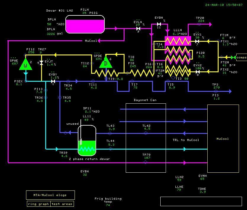
9 Figure 6 Figure 7 9

10 Figure 8 More detailed data, snap shots and data plots can be found in the MTA Cryo electronic log book The controls utilize I/O system and two thermometry crates typical for the Tevatron refrigerators [5]. The second thermometry crate was modified to have much lower current of 9 ua, a factor of 0.01 compare to the standard Tevatron crate in order to decrease a localized heating of the Cernox resistors, and increased the voltage gain by a factor of 100. For comparison a LakeShore module 218 was used to process the signals from Cernox resistors. A standard set of ACNET parameter pages, including F8, F9, F61, and graphical interfaces were developed to monitor the system. All parameters are data logged in 1s or 15s data loggers. The front end FrigMU CPU is located in the MTA building. Additionally, ODH chassis, Benshaw motor starter parameters and LakeShore module 218 are routed to ACNET via IRM module located in the MTA building. Cooldown and Fill rate The cooldown of the refrigerator started from warm conditions on March 18, 2010 and took 8 hours to drop wet engine exhaust temperature below 9K. It took additional 4 hours, or total of 12 hours to build 60% level in the 100 liter 2-phase separator. The bypass valve EVBH was opened up to 80% to alleviate cooldown and fill. The solenoid liquid nitrogen shield level was built to 60% within first 3 hours since connecting cooldown and stayed stable through the entire operations. As the solenoid fill valve EVMH 10
 below 5K.")
11 was opened during the transfer line cooldown, the fill temperature was dropping alongside the helium supply and reached 5K within first 9 hours of cooldown. It took additional 26 hours since reaching level in the 2-phase separator or total of 36 hours to drop the solenoid temperature (as registered by the diode TDHE) below 5K. It took additional 8 hours, or total of 44 hours to build 30% level LLHE in the solenoid. The solenoid temperature was ~4K and the system was fully operational. It took 4 hours (from 8:30 to 12:30 on March 22) to fill the solenoid from 23% to 63%. It is fairly difficult to calculate liquid volume as a function of liquid level prove linear coverage without knowing exact quality of helium, dimensions and position of the probe (as shown on Fig.1), but it maybe estimated that the fill rate was approximately as 30 liters/hour. This is half the fill rate to the on-line Mark-III dewar measured in 2008 for the same refrigerator in the liquefier mode. Certainly the higher heat losses along the different components of the system and flashing while expanding into solenoid might have contributed to lower fill rate. Figure 9 MTA MuCool Refrigeration System Test Run
12 Economics of Nitrogen and Power Consumption Assuming that the helium system is tight, then after initial cooldown and fill the main cost contributors are electricity and nitrogen. The system was cooled down and stably maintained with one Sullair compressor at 220 kw. Average liquid nitrogen boil-off rate in dewar #31 was measured in 2008 as 60 gal/day (or 2%). In 2010 the boil-off rate was measured as 40 to 50 gal/day. Average liquid nitrogen consumption for the refrigerator precool and solenoid shied was measured as 20 gal/hr (including boil-off). This means LN 2 consumption of ~ gal/day and that the 3,000 gal liquid nitrogen dewar #31 must be refilled every 4 days. For the commissioning period we selected 2-day refill period. Helium Inventory and Leaks Helium inventory required to fill and maintain the system cold at 4K is less than 400 liters or 10,640 scf of helium, thus a helium inventory tank at 150 psig should be sufficient to condense and maintain liquid helium levels. The 24-hr helium loss measurement was done from 14:00 on March 27 to 14:00 on March 28 while the helium levels at 2-phase dewar and solenoid were kept constant and the ambient temperature made full day-night cycle. The loss rate was calculated by the mass loss from the 1,360 ft 3 inventory helium tank from 23.7 psig to 16.7 psig. That loss was 0.28 lb/hr or 27 scfh. This is not a significant helium loss. Most likely it can be attributed to o-rings in the power lead flowmeters and other small leaks. Performance and Stability The system demonstrated a very stable overall performance. As shown on Fig.9, the system stably ran in JT mode without wet engine. Both dry and wet engines had to be locked in order to stay below certain maximum speed (typically below 500 rpm) in order to prevent dragging down the compressor discharge and wet engine inlet pressures. It may be beneficial to open clearances for the wet engine so to reduce mass flow through the valves. Plots on Fig.10 show clearly that helium levels in both 2-phase subcooler and solenoid could be maintained at different expander speeds, inlet or exit pressures while expanding helium in wet engine from ~5K to 2-phase. Since the load was maintained stably at different modes, the only optimization was to conserve liquid nitrogen. Plots on Fig. 11 show that the nitrogen usage rate is very dependent on opening of the solenoid shield valve EVDN. Most probably, the valve is oversized and it will be modified for much smaller C v. There was only one system instability, namely sudden pressurization of the solenoid when opening solenoid helium fill valve EVMH. Plots on Fig. 12 show pressure spike PTHE up to 15 psig when opening EVMH from 20 to 50%. The loop needs tuning. An additional pressure sensor will have to be installed upstream of the EVVT solenoid valve to provide better pressure protection of the solenoid. 12


13 Figure 10 System performance plots Figure 11 Liquid nitrogen usage 13
14 Figure 12 Regulation of the solenoid liquid helium level Quench Response On 03/26/10, approximately 11 am (see plots on Fig.13) the solenoid quenched at ~175 amps. That was done intentionally to verify response of the cryo system. At the time the solenoid was filled with ~200L of helium at 4K. The plots show that the solenoid pressure PTHE reached 30 psig thus rupturing the burst disk and venting through the relief vent piping to atmosphere outside the experimental hall. At the same time the ODH sensor located on the ceiling level indicated that oxygen concentration dropped to 10%. Oxygen levels were restored within 2 few minutes by hall's ventilation. All helium was supposed to be relieved to the atmosphere outside the hall. But the 3-inch relief vent line is connected to the vent line from the parallel plate vacuum relief installed on the valve box. It is done to prevent helium venting into experimental hall in that rare case if transfer line or any other component in the valve box ruptures and helium blows into vacuum space. The parallel plate relief is covered with conical reducer to catch helium and divert it to the vent line outside. During the quench event the helium flow in the vent line created pressure drop and the pressure wave back hit the parallel plate conical cover and moved it enough to relieve helium into the hall. After the rupture disk was replaced and the system was checked for tightness, the system was re-cooled and helium level restored without any problems. 14
15 Figure 13 Solenoid quench Cernox Thermometry Eight new Lake Shore Cernox CX-1050 resistors were installed to accurately measure temperature in the helium paths ( In order to measure, scale and use the temperature with Cernox resistors, we used two methods: Eight channel Lake Shore Model 218 monitor with two computer interfaces, IEEE-488 and serial port. The monitor required entering tabulated data in Log(Resistance, Ohm) versus Temperature (deg.k). The module then was computing the temperature in deg.k and transmitted it to ACNET via internet rack module (IRM). This solution offered precise and reliable, though relatively expensive method of using Cernox resistors. Tevatron-style thermometry crate modified to have much lower current of 9 ua, a factor of 0.01 compare to the standard Tevatron crate in order to decrease a localized heating of the Cernox resistors, and increased the voltage gain by a factor of 100. In order to scale measured resistance into temperature, the tabulated data for each individual Cernox resistor was fitted into equation of the following form: 15
16 This fit allowed accuracy of better than +/- 2% at each temperature level over the entire range from 4K to 300K. The raw resistance readings from each of the eight Cernox sensors were routed though a specially designed switch box that allowed easy switching between LakeShore monitor 218 and thermometry crate. Then the readings were compared to evaluate comparative accuracy. It was found that localized heating does not produce significant error (above 0.2K at 4K level) if the switching current is reduced to 9 ua. Still, the issues of low level signal noise were persistent for the Cernox censors located in the experimental hall more than 100 feet away from the thermometry crate. Helium Boil-off Test The helium boil-off rate of the unpowered solenoid was measured on March with fully closed both liquid helium EVMH and liquid nitrogen EVDN valves (Fig. 14). It was measured to be from 0.75 %/hr (with LN 2 shield above 40%) to 1.5 %/hr (with LN 2 shield below 40%). As it is difficult to integrate actual volume of the helium vessel over the depth of the probe, we assume the boil-off level to be 1.1 %/hr. It is important to note that the solenoid temperature stayed between 3.9K and 4.K within the whole range of LHe level. Assuming initial level of LHe in the solenoid as 70% or 200 liters, this translates to 3 Watts heat load for the unpowered solenoid with compromised nitrogen shield. By comparison, previous results indicated 3 4 Watts boil-off for the powered solenoid with nominal helium and nitrogen levels. The solenoid can stay up to 48 hours cold and minimally filled if the nitrogen shield is maintained. Figure 14 Helium Boil-off Test 16
17 V System Improvement List Though the system performed well, there are several areas where additions and improvements are needed to ensure equipment safety, ease of remote operations, redundancy and accuracy. The following need to be done: Complete modifications and commissioning into service the second Sullair Red compressor. That will ensure support of the operations with much greater availability. Mechanical, electrical, controls and safety items need to be completed very similar to those done for the Brown compressor. Install a pressure transmitter in between the solenoid and the electrical cooldown valve EVVT. That pressure transducer will be able to detect pressure in the solenoid with much smaller lag. If the pressure in the solenoid spikes above 10 psig, EVVT should be opened with the additionally created finite state machine. Another finite state machine will need to be created to turn on the electric heater in the cooldown helium path. Replace seat and bullet of the nitrogen fill valve EVDN with smaller orifice valve and stroke it. Find a better tune for the helium fill valve EVMH. Install better thermo insulation for the exposed cold piping (nitrogen vent and helium cooldown to EVVT) as well as the top flange of the solenoid in order to minimize icing and condensation. Investigate electrical noise and accuracy issues for the Cernox resistors read via Tevatronstyle thermometry crate. Create algorisms, finite state machines and graphical interface for helium inventory, startup of the compressors and system cooldown similar to Tevatron. Complete writing and approval of the dangerous operations procedures, operating guides and provide training to AD/Cryo/Operations for providing support for MuCool cryo operations. VI Conclusion MuCool 5T solenoid was successfully cooled down and operated coupled with MTA Brown refrigerator. The system performed as designed with substantial performance margin. All process alarms and interlocks, as well as ODH and fire alarms, were active and performed as designed. The cooldown of the refrigerator started from warm conditions and took 44 hours to accumulate liquid helium level and solenoid temperature below 5K. Average liquid nitrogen consumption for the refrigerator precool and solenoid shield was measured as 20 gal/hr (including boil-off). Helium losses were small (below 30 scfh). The system was stable and with sufficient margin of performance and ran stably without wet expansion engine. Quench response demonstrated proper operation of the relieving devices and pointed to necessity of improving tightness of the relieving manifolds. Boil-off test demonstrated average heat load of 3 Watts for the unpowered solenoid. The solenoid can stay up to 48 hours cold and minimally filled if the nitrogen shield is maintained. A list of improvements includes commencing into operations the second helium compressor and completion of improvements and tune-ups for system efficiency. 17
18 VII References 1. The MuCool Test Area Linac Experimental Facility at Fermilab, D. Errede et al., PAC2003 proceedings, p Recent RF Results from the MuCool Test Area, J. Norem et al., PAC07 proceedings, p The Design and Construction of a Gradient Solenoid for the High Powered RF Cavity Experiment for the Muon Collider, M.Green et al, European Conference on Applied Superconductivity 16-58, LBNL-44188, Commissioning report of the MuCool MTA cryogenic system Brown compressor and refrigerator, M.Geynisman et al, 2008, Fermilab 5. New cryogenic controls for the Tevatron low temperature upgrade, Barry Norris et al, FERMILAB-PUB

19 VII Lessons Leaned MuCool 5T solenoid was again cooled down and operated coupled with MTA Brown refrigerator again on May 3-7, 2010 (see Fig. 15). In the beginning, this cooldown was not successful. We attempted to cool down with wide open EVBH and EVMH fill valves for respectively 2phase dewar and the solenoid. That resulted in low supply pressure PI13 and inefficient JT-ing to the helium volumes. When this was understood, we set the EVBH to regulate PI13=17 psig and EVMH to regulate the wet engine inlet temperature TR27=9K, same way as the satellite refrigerators do. Figure 15 Cooldown May 2010 The system performed as designed with substantial performance margin. All process alarms and interlocks, as well as ODH and fire alarms, were active and performed as designed. After the system was properly configured it took 10 hrs to accumulate level to 60% MCLL11 and 80% MCLLHE. After the system was properly tuned up to regulate MCEVLN on MCLLLN and MCEVX1 on MCTI %, the average liquid nitrogen consumption for the refrigerator precool and solenoid shield was measured as 15 gal/hr (including boil-off). 19


20 Figure 16 LN2 consumption Figure 17 Helium Loss and Levels 20
21 Improvements proposals (05/11/2010): After some discussions with number of people, we are proposing the following to ensure better safety and efficiency in the operations of the 5T magnet. Please review and comment. We feel that though it may result in some inconveniences or delays in operations, it will make operations easier and safer in the long run. 1. We found that cooldown solenoid EVVT must be kept open at all times to keep the solenoid pressure below 10 psig. We do not want to exercise safety reliefs to keep that pressure in check. At the same time, we also found that keeping the solenoid wide open makes the pressure differential between the solenoid and compressor suction low and insufficient to secure good flows through the power leads. We made a test this morning and saw large response in both leads flows and temperatures when we ran the solenoid pressure at 4-5 psig versus less than 2 psig at fully opened EVVT. Therefore, we propose to a) keep the solenoid fully opened at all times with power required for its closing and b) incorporate a back pressure regulator in the cooldown line back to compressor suction to keep the solenoid pressure at 4-5 psig. This is overall good solution for pressure safety; instead of throwing helium to atmosphere in case of pressure surge, we would first vent it to suction. This is an easy fix; all in the frig room, no welding. 2. We are concerned with no-flow conditions for the power leads. This condition can exist should the compressor suction pressure become high, e.g. if the compressor trips off. We would like to incorporate the following hardwired logic. - IF helium level MCLLHE is below 40% - the magnet PS is OFF - [[IF differential pressure (MCPTHS-MCPTHE) is below 0.5 psig] OR [IF compressor is OFF]] AND [magnet PS is ON], then the vent solenoid OPENs to blow downstream of the power leads to atmosphere. This is a medium difficulty fix in the frig room; check valve is required; no welding. 3. We found that nitrogen level in the solenoid is kept so well at helium temperature that it requires almost no supply flow. Therefore, the supply valve is kept closed. This is too bad, as this is the only path for the nitrogen from the LN2 dewar to the magnet via transfer line. With nitrogen flow OFF, the transfer line and the valve box, which are designed without shield flows, keeps warming up. Therefore, we would like to incorporate a turn-around U-tube in the hall valve box to bypass the magnet and turn around the nitrogen flow via existing available control valve back to the refrigerator via one of the non-used helium lines in the transfer line. Then that small nitrogen flow will be vented outside. The control loop will keep the shield temperature at the predefined temp level. 21
FAILURE SCENARIOS AND MITIGATIONS FOR THE BABAR SUPERCONDUCTING SOLENOID
 SLAC-PUB-11601 December 2005 FAILURE SCENARIOS AND MITIGATIONS FOR THE BABAR SUPERCONDUCTING SOLENOID EunJoo Thompson, A. Candia, W. W. Craddock, M. Racine, J. G. Weisend II Stanford Linear Accelerator
Magnet and RF Cavity Test Stand Design. Tom Peterson, SLAC USPAS January, 2017
 Magnet and RF Cavity Test Stand Design, SLAC Outline Test dewars and test stands Saturated bath test dewars Double bath test dewars SRF test cryostats SRF cryomodule test stands Horizontal magnet test
Safety in Cryogenic Operations at RHIC *
 Safety in Cryogenic Operations at RHIC * Anthony Nicoletti, Dewey Lederle, Ahmed Sidi-Yehklef, Tom Tallerico, Roberto Than, Joe Tuozzolo Collider-Accelerator Department Brookhaven National Laboratory Upton,
DRAFT. Operating Procedures for the NPDGamma Liquid Hydrogen Target in TA-53, Building MPF-35
 Operating Procedures for the NPDGamma Liquid Hydrogen Target V0.03 11/26/05 1 DRAFT Operating Procedures for the NPDGamma Liquid Hydrogen Target in TA-53, Building MPF-35 Version 0.03 November 26, 2005
Fermilab MTF Cryogenic System & Vertical RF Cavity Test Facility. Yuenian Huang, on behalf of Fermilab, TD/TID May 11, 2006
 Fermilab MTF Cryogenic System & Vertical RF Cavity Test Facility Yuenian Huang, on behalf of Fermilab, TD/TID May 11, 2006 1 Magnet Test Facility (MTF) Tevatron magnet test stands Testing temperature range
Cryogenics of SRF Spoke Cavity Development at SMTF
 Cryogenics of SRF Spoke Cavity Development at SMTF Michael White SRF Development Technical Division Fermi National Accelerator Laboratory May 11, 2006 Overview of Topics SMTF Overview CTF Cryogen Supply
JANIS OPERATING INSTRUCTIONS FOR SUPERCONDUCTING MAGNET CRYOSTATS
 OPERATING INSTRUCTIONS FOR SUPERCONDUCTING MAGNET CRYOSTATS INTRODUCTION The Janis Research Company's Superconducting Magnet/Cryostat System is one of the most versatile tools available to the scientist
D R A F T. Operating Procedures for the NPDGamma Liquid Hydrogen Target at the BL 13. Version 1.00
 D R A F T Operating Procedures for the NPDGamma Liquid Hydrogen Target at the BL 13 Version 1.00 October 06, 2010 Operating Procedures for the NPDGamma Liquid Hydrogen Target V1.00 6/10/10 2 Table of Content
INTRODUCTION. The Quantum Technology system has the following advantages:, as it does not need plastic gas-bags which are volume-consuming,
 1 INTRODUCTION Quantum Technology is a leading scientific equipment supplier. For the last thirty years we served our customers by tailoring our products to each customer s unique requirements. Quantum
Series Environmental Chambers
 3119-600 Series Environmental Chambers Challenges in Non-Ambient Testing Testing at non-ambient temperatures adds another layer of challenges to your testing laboratory. Ensuring you get accurate and stable
Microscopy Cryogenic WORKSTATION. Performance by Design
 CRYO Microscopy Cryogenic WORKSTATION Optical cryostat for use in microscopy and spectroscopy Performance by Design RC102-CFM Microscopy Cryostat offers fast cooldown, high efficiency, excellent temperature
Variable Temperature Storage Dewar Mount Inserts
 Variable Temperature Storage Dewar Mount Inserts All inserts are available for either Liquid Helium or Liquid Nitrogen Dewars! DStat - External cryostat with insert leg DStatMag - Super Conducting Magnet
Figure 1 The LHC cryogenic islands and plants layout
 The LHC cryogenic operation for first collisions and physics run Brodzinski K, Barth K, Benda V, Bremer J, Casas-Cubillos J, Claudet S, Delikaris D, Ferlin G, Fernandez Penacoba G, Perin A, Pirotte O,
Status on the DFBXF commissioning
 Status on the DFBXF commissioning Cryogenic Performance Panel C. Darve March 28th 2008 1 Procedure steps and checks Based on S78 commissioning (R. Rabehl 05 July 2007): Cool-down part 1 (cool-down from
Earlier Lecture. In the earlier lecture, we have seen Kapitza & Heylandt systems which are the modifications of the Claude System.
 17 1 Earlier Lecture In the earlier lecture, we have seen Kapitza & Heylandt systems which are the modifications of the Claude System. Collins system is an extension of the Claude system to reach lower
SPECIFICATION FOR AN MRBR 9.4 TESLA/310MM/AS CRYO-COOLED MAGNET SYSTEM
 SPECIFICATION FOR AN MRBR 9.4 TESLA/310MM/AS CRYO-COOLED MAGNET SYSTEM Prepared by:- Magnex Scientific Limited The Magnet Technology Centre 6 Mead Road Oxford Industrial Park Yarnton, Oxford OX5 1QU, UK
First Experimental Data of the Cryogenic Safety Test Facility PICARD
 First Experimental Data of the Cryogenic Safety Test Facility PICARD C. Heidt, A. Henriques, M. Stamm and S. Grohmann 26 th International Cryogenic Engineering Conference 2016 in New Delhi, India KIT,
An Investigative and Synoptic Review on Helium Liquefaction Using a Commercial 4 K Gifford- McMahon Cryocooler
 An Investigative and Synoptic Review on Helium Liquefaction Using a Commercial 4 K Gifford- McMahon Cryocooler Mahesh N 1, S A Mohan Krishna 2 1 PG Student, Vidyavardhaka College of Engineering, Mysore,
AN EXPERIMENTAL INVESTIGATION ON HELIUM LIQUEFACTION USING TWO-STAGE GIFFORD McMAHON CRYOCOOLER
 P P P International Journal of Scientific Engineering and Applied Science (IJSEAS) - Volume-1, Issue-6, September 2015 AN EXPERIMENTAL INVESTIGATION ON HELIUM LIQUEFACTION USING TWO-STAGE GIFFORD McMAHON
Procedure for Operating Columbia (Nevis) LHe Electron Bubble Chamber Cryostat. Version 5.1
 LHe Electron Bubble Chamber Cryostat. Version 5.1") Project: Novel Electron Bubble Particle Detector Procedure for Operating Columbia (Nevis) LHe Electron Bubble Chamber Cryostat Version 5.1 (Using side filling line) Hand Processed Changes HPC No. Date
Project: Novel Electron Bubble Particle Detector Procedure for Operating Columbia (Nevis) LHe Electron Bubble Chamber Cryostat Version 5.1 (Using side filling line) Hand Processed Changes HPC No. Date
Cryogenics The Basics. Lesson 2 D. Kashy
 Cryogenics The Basics Lesson 2 D. Kashy Lecture 1 Review Lesson 1 - Objectives Looked at common liquids and gases to get a feeling for their properties Looked at Nitrogen and Helium Discussed Pressure
Research activities on cryogenic safety
 Research activities on cryogenic safety Steffen Grohmann, Carolin Heidt, Andre Henriques (CERN), Christina Weber European Cryogenics Days, CERN, June 9-10, 2016 INSTITUTE OF TECHNICAL PHYSICS (ITEP) INSTITUTE
- Brief overview of the Tevatron cryogenic system - Operations for Run II
 - Brief overview of the Tevatron cryogenic system - Operations for Run II * reliability and availability of the overall system and its components * helium losses and cryogens inventory (vendors, distribution,
Current Leads for Cryogenic Systems
 Current Leads for Cryogenic Systems American Magnetics Inc. s (AMI) Vapor Cooled Current Leads provide reliable and consistent electrical current transfer from room temperature (300K) to a Liquid Helium
AC : MEASUREMENT OF HYDROGEN IN HELIUM FLOW
 AC 2010-2145: MEASUREMENT OF HYDROGEN IN HELIUM FLOW Randy Buchanan, University of Southern Mississippi Christopher Winstead, University of Southern Mississippi Anton Netchaev, University of Southern Mississippi
EXPERIENCE WITH A PRE-SERIES SUPERFLUID HELIUM TEST BENCH FOR LHC MAGNETS
 EUROPEAN ORGANIZATION FOR NUCLEAR RESEARCH European Laboratory for Particle Physics Large Hadron Collider Project LHC Project Report 388 EXPERIENCE WITH A PRE-SERIES SUPERFLUID HELIUM TEST BENCH FOR LHC
MEDICAL EQUIPMENT CATALOG
 THE MOST TRUSTED MEDICAL EQUIPMENT IN NORTH AMERICA MEDICAL EQUIPMENT CATALOG Total Components Including Bulk Oxygen Supply, Back up and Delivery Equipment Designs for High Pressure, Liquid or Bulk Applications
Helium recovery at the National High Magnetic Field Laboratory
 IOP Conference Series: Materials Science and Engineering PAPER OPEN ACCESS Helium recovery at the National High Magnetic Field Laboratory Related content - Helium recovery and purification at CHMFL J Li,
RC102 & RC110 Sample in Vacuum Continuous Flow Cryogenic Workstation Cryostats
 RC102 & RC110 Sample in Vacuum Continuous Flow Cryogenic Workstation Cryostats www.cryoindustries.com INDUSTRIES RC102 & RC110 Sample in Vacuum Continuous Flow Cryogenic Workstation Cryostats Designed
NPDGamma LH2 Target OJT Lesson Plan: Senior Operator for the NPDGamma LH2 Target Operators
 0. Introduction Object of this on-the-job Training (OJT) Lesson Plan is to train Senior Operators for the NPDGamma LH2 target system. After successful of this OJT and authorization by line management Senior
Bubble Chamber Detector System
 Bubble Chamber Detector System 1 ANL Bubble Chamber Lead designer and fabricator Brad DiGiovine (ANL) April 2009 Chamber Received Full Operation Authorization for (C 4 F 10 ) February 2010 First Bubble
TIGHTNESS. Glass sealing Thanks to our glass-sealing technology, ODU products can meet the most demanding tightness requirements.
 TIGHTNESS Glass sealing Thanks to our glass-sealing technology, ODU products can meet the most demanding tightness requirements. ODU has the necessary expertise for developing and manufacturing connectors
TANK MANAGER FOR TWO TANKS OPERATING MANUAL. 10/31/11 C-More T6C L color touch panel
 TANK MANAGER FOR TWO TANKS OPERATING MANUAL 10/31/11 C-More T6C L color touch panel 1 TABLE OF CONTENTS GENERAL...3 INSTALLATION...4 STONE TEST PROCEDURE...7 OPERATIONAL SUMMARY...7 AUTO CARBONATION...10
To be published in the proceeding of ICEC-22, Seoul Korea, July 2008 MICE Note 231 1
 270 mm o be published in the proceeding of ICEC-22, Seoul Korea, 21-25 July 2008 MICE Note 231 1 180 mm ests of Four P-415 Coolers Installed in the Drop-in Mode Green a, M. A., and Wang b, S.. a) Lawrence
DD2 Site Preparation Checklist Hardware Site Preparation Specification
 Thank you for purchasing an Agilent instrument. To get you started and to assure a successful and timely installation, please refer to this specification or set of requirements. Correct site preparation
RDK-408D2 Cold Head. Technical Manual. SHI-APD Cryogenics Inc Vultee Street Allentown, PA U.S.A. Revision A: September 2005
 RDK-408D2 Cold Head Technical Manual SHI-APD Cryogenics Inc. 1833 Vultee Street Allentown, PA 18103-4783 U.S.A. Revision A: September 2005 (Reference SHI Manual: December 18, 2003 266404A CD32ZZ-160A)
A Rationale for Pressure Relief Device(s) Qualification Requirements (LH2)
 Qualification Requirements (LH2)") UN-GTR PART A INSERTION Stand 09.02.2011, 17:20 Uhr A.3.3 HYDROGEN STORAGE SYSTEM The hydrogen storage system consists of all components that form the primary pressure boundary of the stored hydrogen in
UN-GTR PART A INSERTION Stand 09.02.2011, 17:20 Uhr A.3.3 HYDROGEN STORAGE SYSTEM The hydrogen storage system consists of all components that form the primary pressure boundary of the stored hydrogen in
PRad Target. Chris Keith JLab Target Group
 PRad Target Chris Keith JLab Target Group Target Overview & Components Target Software Hazard Analysis and Mitigation Target Status, Performance& Remaining Work Installation Schedule Nov. 12, 2015 PRad
CVI Valve Line. Exceeds the industry s highest standards for reliability and performance
 CVI Valve Line Exceeds the industry s highest standards for reliability and performance Available in the most standard models with the shortest lead times in the industry Exceptional quality every CVI
ACCURATE PRESSURE MEASUREMENT FOR STEAM TURBINE PERFORMANCE TESTING
 ACCURATE PRESSURE MEASUREMENT FOR STEAM TURBINE PERFORMANCE TESTING Blair Chalpin Charles A. Matthews Mechanical Design Engineer Product Support Manager Scanivalve Corp Scanivalve Corp Liberty Lake, WA
Loss of Vacuum Experiments on a Superfluid Helium Vessel
 1 Loss of Vacuum Experiments on a Superfluid Helium Vessel Stephen M. Harrison 1 Abstract The Alpha Magnetic Spectrometer (AMS) is a particle physics experiment for use on the International Space Station
L 100. Bubble-Tube Level System. Installation, Operation and Maintenance Instructions
 L 100 Bubble-Tube Level System Installation, Operation and Maintenance Instructions Figure 1 Contents Section Description Page 1.0 Introduction 2 2.0 Specifications 3 3.0 Installation 3 4.0 Warranty 6
APPS-160 Gen 2 User Manual
 APPS-160 Gen 2 User Manual Applicable Products: PN 11914406 - APPS-160 10 to 50 PSIG operating pressure PN 11918618 - APPS-160 40 to 85 PSIG operating pressure Rev 9/16/2004 Chart Ind. www-chart-ind.com
Improve Reliability of Turbomachinery Lubrication and Sealing Systems
 Improve Reliability of Turbomachinery Lubrication and Sealing Systems Fisher Pressure Control Solutions For Turbomachinery Applications Protect the integrity of your Turbomachinery support system Turbomachinery
Hill PHOENIX Second Nature Medium Temperature Secondary Refrigeration Start-Up Guide
 Hill PHOENIX Second Nature Medium Temperature Secondary Refrigeration Start-Up Guide Secondary Coolant System Start-Up Procedures June 2006 Produced by the Hill PHOENIX Learning Center DISCLAIMER This
Instruction Manual VCG-6
 Specifications Amps / Volts requirements 400 ma @ 24 VDC Propane pressure (VCG-6LP) 11 WC / 2.8 kpa Natural Gas pressure (VCG-6NG) 4.5 WC / 1.15 kpa Cu ft per hour / CO2 3-6 SCFH BTU Rating (Variable)
TWC Services, Inc. Structured On-The-Job Training for JT- 1, 2, 3
 TWC Services, Inc. Structured On-The-Job Training for JT- 1, 2, 3 The following tasks parallel the Jr. Tech (JT-1, 2, 3) description and development plan and use the Refrigeration and Air conditioning
FLUID POWER FLUID POWER EQUIPMENT TUTORIAL ACCUMULATORS. This work covers part of outcome 2 of the Edexcel standard module:
 FLUID POWER FLUID POWER EQUIPMENT TUTORIAL ACCUMULATORS This work covers part of outcome 2 of the Edexcel standard module: UNIT 21746P APPLIED PNEUMATICS AND HYDRAULICS The material needed for outcome
Cryostream 800 Series
 Cryostream 800 Series Cryostream 800 Series Nearly 30 years after the invention of the first Cryostream Cooler, Oxford Cryosystems is proud to announce the launch of the new 800 series Cryostream. The
Improving distillation tower operation
 Improving distillation tower operation Measuring differential pressure across long sections of distillation columns has always been challenging, but purpose-built sensor systems provide a solution Fast
Cryogenics is the science of ultra low temperatures. Low temperatures are achieved by the liquefaction of gases.
 CRYOGENICS SAFETY Introduction Cryogenics is the science of ultra low temperatures. Low temperatures are achieved by the liquefaction of gases. The gases which are most widely used in industry and research
Inert Air (N2) Systems Manual
 Systems Manual") INSTRUCTION MANUAL Inert Air (N2) Systems Manual N2-MANUAL 2.10 READ AND UNDERSTAND THIS MANUAL PRIOR TO OPERATING OR SERVICING THIS PRODUCT. GENERAL INFORMATION Positive pressure nitrogen gas pressurizing
INSTRUCTION MANUAL Inert Air (N2) Systems Manual N2-MANUAL 2.10 READ AND UNDERSTAND THIS MANUAL PRIOR TO OPERATING OR SERVICING THIS PRODUCT. GENERAL INFORMATION Positive pressure nitrogen gas pressurizing
Gerald D. Anderson. Education Technical Specialist
 Gerald D. Anderson Education Technical Specialist The factors which influence selection of equipment for a liquid level control loop interact significantly. Analyses of these factors and their interactions
v. Size shall be specified on drawings.
 SPECIFICATION FOR VACUUM INSULATED PIPING Part 1 General 1. Submittals a. After award of contract and before executing any manufacturing, shop drawings and specifications shall be submitted to the customer
Drift-Chamber Gas System Controls Development for the CEBAF Large Acceptance Spectrometer
 Drift-Chamber Gas System Controls Development for the CEBAF Large Acceptance Spectrometer M. F. Vineyard, T. J. Carroll, and M. N. Lack Department of Physics University of Richmond, VA 23173 ABSTRACT The
BIMA cryogenics (Dick Plambeck, 18jan2007)
") BIMA cryogenics (Dick Plambeck, 18jan2007) Normal operation. Monitor from the antennas > 6-meter > receivers multiple> cryo rtd page. Troubleshooting. sensor what is it? normal range stage1 outer dewar
BIMA cryogenics (Dick Plambeck, 18jan2007) Normal operation. Monitor from the antennas > 6-meter > receivers multiple> cryo rtd page. Troubleshooting. sensor what is it? normal range stage1 outer dewar
National Accelerator Laboratory
 Fermi National Accelerator Laboratory FERMILAB-Conf-97/268 A 1400 Liter 1.8K Test Facility T.J. Peterson, R.J. Rabehl and C.D. Sylvester Fermi National Accelerator Laboratory P.O. Box 500, Batavia, Illinois
METHODS TO PREVENT THE PREMATURE ACTIVATION OF RELIEF DEVICES ON TRANSPORT TANKS
 METHODS TO PREVENT THE PREMATURE ACTIVATION OF RELIEF DEVICES ON TRANSPORT TANKS IGC Doc 184/14/E EUROPEAN INDUSTRIAL GASES ASSOCIATION AISBL AVENUE DES ARTS 3-5 B 1210 BRUSSELS Tel: +32 2 217 70 98 Fax:
TECHNICAL INFORMATION
 TECHNICAL INFORMATION Installation, Operation, and Maintenance Balston Model 75-77 Nitrogen Generator Figure 1-75-77 Overall Dimensions These instructions must be thoroughly read and understood before
EXPERIENCE WITH CRYOGENICS SAFETY, PROBLEMS AND SOLUTIONS
 EXPERIENCE WITH CRYOGENICS SAFETY, PROBLEMS AND SOLUTIONS Rajiv Sharma and Cryogenic Division SST-1 IPR, Gandhinagar 33rd DAE Safety & Occupational Health Professionals Meet at IPR, Gandhinagar, 23-25
STANDARD FOR CONTROL VALVE SEAT LEAKAGE
 11-3 STANDARD FOR CONTROL VALVE SEAT LEAKAGE 1. PURPOSE 1.1 This standard establishes a series of seat leakage classes for control valves and defines the test procedures. 2. SCOPE & LIMITATIONS 2.1 Selection
H 2 O Bubble Chamber Superheated Active Target System. Safety and Systems Overview B. DiGiovine
 H 2 O Bubble Chamber Superheated Active Target System Safety and Systems Overview B. DiGiovine Physics Division and Bubble Chambers April 2009 First Bubble Chamber Received Full Operation Authorization
Detector Carrier Gas Comments Detector anode purge or reference gas. Electron Capture Nitrogen Maximum sensitivity Nitrogen Argon/Methane
 Gas requirements Gases for packed columns The carrier gas you use depends upon the type of detector and the performance requirements. Table 520-1 lists gas recommendations for packed column use. In general,
Level MEASUREMENT 1/2016
 Level MEASUREMENT 1/2016 AGENDA 2 A. Introduction B. Float method C. Displacer method D. Hydrostatic pressure method E. Capacitance method G. Ultrasonic method H. Radar method I. Laser method J. Level
The HumiPyc - Model 1 - Gas Pycnometer; Density, Moisture, Permeation Analyzer; RH sensor Calibrator
 The HumiPyc - Model 1 - Gas Pycnometer; Density, Moisture, Permeation Analyzer; RH sensor Calibrator Designed, built, and supported by InstruQuest Inc. Temperature controlled, multi-technique volumetric
NGP-250/500 Nitrogen Generator Quick Start Guide
 NGP-250/500 Nitrogen Generator Quick Start Guide Version: A July 2013 Potter Electric Signal Company, LLC 5757 Phantom Dr., Suite 125 P. O. Box 42037 Hazelwood, MO 63042 Phone: (314) 595-6900 Document
Table of Contents Want full page pictures with most important parts labeled in the beginning.
 1 Table of Contents Want full page pictures with most important parts labeled in the beginning. Precool Procedures (Perform before cooling down): 1. Check N2 and 4He gas tanks to be sure that there is
Trifecta High-Pressure Systems
 Trifecta High-Pressure Systems CONSULTING SYSTEM DESIGN INSTALLATION COMMISSIONING TRAINING Trifecta Product Catalog www.chartindustries.com TABLE OF CONTENTS About Chart Inc. 3 Trifecta Applications &
FAILURE AND HAZARD ANALYSIS OF THE NPDGAMMA LH2 TARGET SYSTEM
 FAILURE AND HAZARD ANALYSIS OF THE NPDGAMMA LH2 TARGET SYSTEM Revision: 0.00 Edited by: Seppo Penttila, November 10, 2010 1. General The RSS 8305.0 Installation, Commissioning, and Operation of the NPDGamma
hydro-pac, inc. Low-Pressure Gas Compressors 1500 to 6000 PSI
 hydro-pac, inc. LX-SERIES Low-Pressure Gas Compressors 1500 to 6000 PSI hydro-pac, inc. LX-SERIES Features Hydro-Pac LX-SERIES Gas Compressors feature: Oil-free non lubricated gas pistons and cylinders
Cryomodule Maintenance Workshop Maintenance, Repair Strategies, and Fault Scenarios. J. Ozelis Senior SRF Coordinator
 Cryomodule Maintenance Workshop Maintenance, Repair Strategies, and Fault Scenarios J. Ozelis Senior SRF Coordinator Outline for Discussions Maintenance - routine/preventative maintenance Schedules Specific
Bulletin TCR-104 & 109 Filling and adding to the Glycol pressure system
 Bulletin 061013 TCR-104 & 109 Filling and adding to the Glycol pressure system 1. Glycol System and air On this model the glycol system is a closed system, the glycol is not exposed to the air. No external
Gas density monitor With integrated transmitter Model GDM-100-TI
 SF 6 gas solutions Gas density monitor With integrated transmitter Model GDM-100-TI grid Products WIKA data sheet SP 60.05 for further approvals see page 5 Applications Gas density monitoring of closed
PILOT OPERATED RELIEF VALVE SAFETY PRODUCTS THAT PROTECT EQUIPMENT, LIVES & THE ENVIRONMENT
 PILOT OPERATED RELIEF VALVE SAFETY PRODUCTS THAT PROTECT EQUIPMENT, LIVES & THE ENVIRONMENT Model Number Model Description Page # Pilot operated Relief Valves Pilot Operated Relief Valves 3-27 Operation
BACK PRESSURE / SUSTAINING
 In many liquid piping systems, it is vital that line pressure is maintained within relatively narrow limits. This is the function of the 108 Pressure Relief / Back Pressure Series of the OCV control valves.
Characterizers for control loops
 Characterizers for control loops By: F. G. Shinskey (May 1999) Introduction Commercial controllers such as the PID series (proportional, integral, derivative, and their combinations) are linear devices
IMECE IMECE2011-6
 Proceedings of the ASME 2011 International Mechanical Engineering Congress & Exposition IMECE2011 November 11-17, 2011, Denver, Colorado, USA Cryogenic Temperature Stabilization of the Daikin 308 Cryocooler
BACK PRESSURE / SUSTAINING
 SPECIFICATIONS DIMENSIONS In many liquid piping systems, it is vital that line pressure is maintained within relatively narrow limits. This is the function of the 108 Pressure Relief / Back Pressure Series
CB7 Bayonets Male & Female 1/4", 3/8, & 1/2 Size
 12501 Telecom Drive, Tampa, FL 33637 Ph: (813) 978-1000 Fax: (813) 977-3329 www.cpc-cryolab.com INSTALLATION, OPERATING, AND MAINTENANCE INSTRUCTIONS 17/3.5.6 Rev. 0 CB7 Bayonets Male & Female 1/4", 3/8,
Oxidation Stability of Gasoline and Aviation Fuels
 Oxidation Stability of Gasoline (Induction Period Method) Oxidation Stability of Aviation Fuels (Potential Residue Method) Test Method Provides an indication of the tendency of gasoline and aviation fuels
HANDBOOK SAFETY DEVICES. Ed SAFETY DEVICES DS-ED 01/ ENG 1
 HANDBOOK Ed. 2017 DS-ED 01/2017 - ENG 1 CHAPTER 9 BURSTING DISC DEVICES IN SERIES 3070 SCOPE Use: protection against possible overpressure of the apparatuses listed below, with regard to the operating
Technical Information
 Technical Information Installation, Operation, Installation, Operation and Maintenance and Maintenance Manual Manual Balston Model 75700-K728 Nitrogen Generator Figure 1-75700-K728 Overall Dimensions These
Exercise 5-2. Bubblers EXERCISE OBJECTIVE DISCUSSION OUTLINE. Bubblers DISCUSSION. Learn to measure the level in a vessel using a bubbler.
 Exercise 5-2 Bubblers EXERCISE OBJECTIVE Learn to measure the level in a vessel using a bubbler. DISCUSSION OUTLINE The Discussion of this exercise covers the following points: Bubblers How to measure
The Discussion of this exercise covers the following points:
 Exercise 5-3 Wet Reference Leg EXERCISE OBJECTIVE Learn to measure the level in a vessel using a wet reference leg. DISCUSSION OUTLINE The Discussion of this exercise covers the following points: Measuring
Installation restrictions for length of sections should also be noted.
 Since 1966 CHART (formerly MVE) has specialized in the design and fabrication of custom cryogenic piping for liquid nitrogen, oxygen, argon, helium, and hydrogen in pipe sizes ranging from 1/4" through
Periodic Survey of Fuel Installations on Ships other than Liquefied Gas Carriers utilizing gas or other low flash point fuels
 (Jan 2017) Periodic Survey of Fuel Installations on Ships other than Liquefied Gas Carriers utilizing gas or other low flash point fuels CONTENTS 1. Application 2. Special Survey 2.1 Schedule 2.2 Scope
TechTalk. Purging for Delayed Coking. Understanding purging system design in heavy-fouling applications. Outline
 Page 1 of 6 TechTalk Understanding purging system design in heavy-fouling applications Purging for Delayed Coking Outline Introduction In high-fouling applications such as heavy oil processing and What
SINGLE VALVE WITH LOW-FLOW BYPASS
 CONTROL VALVES Pressure Reducing Valve Sizing Guide Sizing pilot operated reducing valves is not a complicated process. It starts with determining requirements and following these guidelines in valve size
Trifecta Systems. Cryogenic Equipment for High Performance Gas Supply. Trifecta Product Catalog
 Trifecta Systems Cryogenic Equipment for High Performance Gas Supply C O N S U LT I N G S Y S T E M D E S I G N I N S TA L L AT I O N C O M M I S S I O N I N G T R A I N I N G Trifecta Product Catalog
Review of the Hall B Gas System Hardware. George Jacobs
 of the Hardware George Jacobs DSG Staff 2 Hall B Gas Utilities for detectors Drift Chamber (DC) Low Threshold Cherenkov Counter (LTCC) Micromegas Vertex Tracker (MVT) Forward Tagger (FT) Ring Imaging Cherenkov
PREVENTION OF EXCESSIVE PRESSURE DURING FILLING OF CRYOGENIC VESSELS
 PREVENTION OF EXCESSIVE PRESSURE DURING FILLING OF CRYOGENIC VESSELS AIGA 054/08 GLOBALLY HARMONISED DOCUMENT Asia Industrial Gases Association 3 HarbourFront Place, #09-04 HarbourFront Tower 2, Singapore
ANL Bubble Chamber Superheated Active Target System
 ANL Bubble Chamber Superheated Active Target System N 2 O and C 2 F 6 as Active Fluids B. DiGiovine Physics Division and Bubble Chambers April 2009 First Bubble Chamber Received Full Operation Authorization
FUEL GAS FIRING CONTROL RJ (Dick) Perry Safety Systems Consultant 6 June 2016
 Perry Safety Systems Consultant 6 June 2016") INTRODUCTION Fired equipment such as Heaters and Boilers, normally have to comply with either NFPA 85/86 or API 556 for North America and some other countries which apply such standards, or EN 746-2 for
INTRODUCTION Fired equipment such as Heaters and Boilers, normally have to comply with either NFPA 85/86 or API 556 for North America and some other countries which apply such standards, or EN 746-2 for
Radar, Ultrasonic and RF Level Transmitters
 Radar, Ultrasonic and RF Level Transmitters Both measures the time it takes the wave to travel between the transmitter and that reflected wave off the surface of the material to reach the transmitter again.
The Ins and Outs of I/P Transducers
 The Ins and Outs of I/P Transducers By Mark B. Levine, ControlAir Inc. General description I/P transducers are versatile instruments that use an electrical control signal to proportionally regulate gas
Advanced Pump Control for Irrigation Applications
 Advanced Pump Control for Irrigation Applications Paul Nistler VFD Applications Engineer And Julian Atchia Director of Research and Development SJE Rhombus 22650 County Hwy 6 Detroit Lakes MN 56502 Executive
Copeland Discus with CoreSense Diagnostics January 2011
 Copeland Discus with CoreSense Diagnostics January 2011 Slide 1 1/27/2011 5:48 PM Discus with CoreSense Diagnostics Case Studies Supermarket In Columbus, Ohio Saves $4,500 With Discus with CoreSense Diagnostics
Safety Aspects and Design of the Vent Isolation Chamber. Prepared: W.M. Snow Checked: H. Nann Approved: W. M. Snow
 Safety Aspects and Design of the Vent Isolation Chamber Prepared: W.M. Snow Checked: H. Nann Approved: W. M. Snow 1. Scope This document addresses the safety aspects and design of the vent isolation chamber
Chem Bio Liquid Nitrogen Facility
 Chem Bio Liquid Nitrogen Facility Who: Where: When: What: How: Open to anyone working in a Western research lab that requires LN2 for their research. To become a registered user, you must attend a training
MASS FLOW SYSTEMS MASS FLOW MEASURING, CONTROLLING AND BLENDING SYSTEMS
 MASS FLOW SYSTEMS MASS FLOW MEASURING, CONTROLLING AND BLENDING SYSTEMS Using state-of-the-art measuring and microprocessor technologies, Advanced has assembled a series of systems which can measure mass