The Davis Besse Nuclear Power Plant Three Mile Island Accident Precursor Event September 24, 1977
|
|
|
- Dominick Carr
- 6 years ago
- Views:
Transcription
1 The Davis Besse Nuclear Power Plant Three Mile Island Accident Precursor Event September 24, 1977 Copyright Mike Derivan 2014
2 On September 24, 1977 the Davis Besse Nuclear Power Plant near Toledo Ohio experienced an event remarkably similar to the Three Mile Island Accident. The Reactor Coolant System response to both events is virtually identical for about twenty minutes. The failure of the Nuclear Industry and its Regulatory body, the NRC, to correctly understand the significance of the Davis Besse event put the TMI Operators in exactly the same position eighteen months later. The results of this failure had dire consequences for both the US Nuclear Industry and the reputations of the TMI Operators. This presentation, and its accompanying text document, are my attempt to tell the truth, the whole truth, and nothing but the truth about the Root Cause of the TMI Accident. Mike Derivan
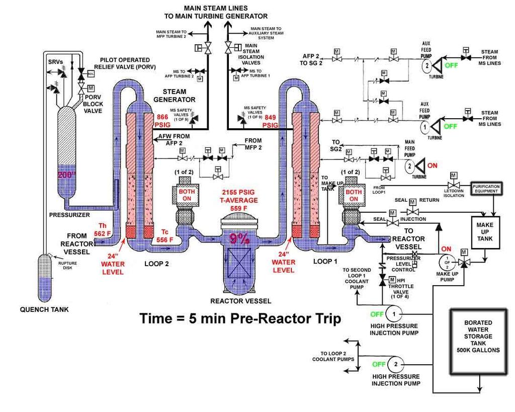
3 The next frame shows a simplified drawing of the associated plant systems at Davis Besse and the plant initial conditions prior to the event. All time references on the slides are relative to the time the Davis Besse Operator manually tripped the reactor early in the event. Additional narrative will accompany the slide presentation.
4
5
6
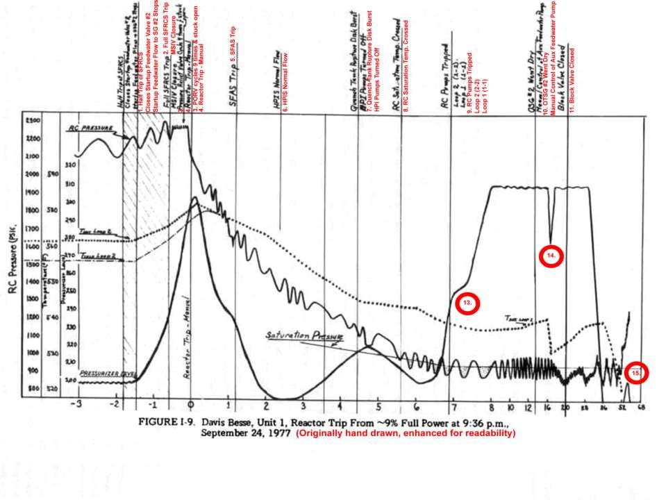
7 Between the previous frame and the next frame the Reactor Coolant System (RCS) is undergoing a heat up transient. When the SFRCS actuation closed the Main Steam Isolation Valves with the Reactor at 9% power, stopping the steam flow out of both Steam Generators, the heat removal (heat sink) for the RCS was lost. With the Reactor still generating 9% power there is no place for that power to go, except into the coolant water of the RCS and the secondary side water level trapped in the Steam Generators. A very small amount of heat removal is afforded by the steam to run the Aux Feed Pump Turbines. The net affect of that coolant water heat up is the water expands pushing the Pressurizer water level up and squeezing the steam bubble in the Pressurizer into a constantly decreasing volume. This causes the system pressure to increase also. This pressure increase is what caused the PORV to lift. Once the PORV lifted, and stuck open, two opposite affects are competing with respect to system pressure. The stuck open PORV is decreasing pressure while the expanding water into the Pressurizer from the coolant system water expansion wants to increase the pressure. The water expansion is continuing because the Reactor is still critical (running) generating power. In our case the PORV is winning, because the system pressure is decreasing. In this short duration pressure transient the system pressure is probably hanging between the Reactor low pressure trip and high pressure trip window a bit. But the system pressure response vs. time plot clearly shows the pressure was on the way to the low pressure Reactor trip setpoint. The subtle influence on this pressure transient is the fact we had a positive moderator coefficient of reactivity at this time in the Reactor life cycle. And I m convinced the speed of the coolant system heat up was being driven by an ever increasing Reactor power level. But the power level data I have does not include that plot. But it always makes me wonder if a slightly different sequence might have been possible. One where the RCS heat up and the Pressurizer level in surge was controlling the pressure. That might lead to what Operators refer to as A truly eye watering event.
8
9
10
11 Now I know what you re thinking, Why on earth did you guys shutdown those HPI Pumps when you had a leak? My simple answer is We were trained to do it, but of course that leads to another question, doesn t it? We ll get to that too, but right now things are about to get worse. Remember before you get too judgmental, you ve already spent more time watching this Power Point Slide Show than we have spent dealing with this event in real time in a real plant. We re only at five minutes. And Oh, by the way, we were emphatically trained to never let the HPI Pumps overfill the Pressurizer level. At the time we shut them down, that level was 230 and increasing, while the desired post Reactor Trip level setpoint was 100.
12
13
14
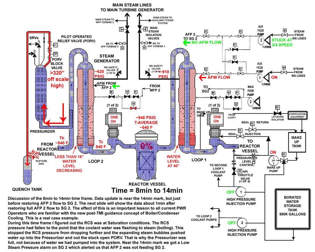
15 Between 8 minutes and about 14 minutes post Reactor trip the RCS conditions were relatively stagnant. This is the first time we had a chance to focus on the meaning of the low RCS pressure and pegged out high Pressurizer Level, as there were no other pressing tasks requiring our attention during this time frame. During the time frame from event start until now I had been looking at the low pressure and high level as 2 independent unrelated problems. At least the pressure had gone in an expected direction on the Reactor trip, albeit way too far. But that Pressurizer had me stumped to the point I actually had the thought something was going on we hadn t been told about; and if I could just get the plant drawing straight lines I could figure it out. On a gut level it was impossible considering just some thumb rules for the Pressurizer. One inch of level equals 30 gallons. One degree of T-average equals two inches of level. I had watched it go from 200 to over 320 in 2 minutes. That s over 3000 gallons, or over 1500 GPM; impossible with our pumps. But I never doubted that the indicator was correct (we had 3). According to the data plots, the RCS temperature actually started a slow heat up at about the 8 minute mark which continued through this time period. I remember I had been intently focused on the RCS pressure dropping, wondering when it was going to stop. It stopped dropping and bottomed out at about 950PSIG during the 8 to 10 minute time frame. That really got my attention. As much as I wanted to see it stop dropping, what soaked in was that we had done nothing to cause it to stop. There had to be a reason. Looking at the plant temperature and pressure it dawned on me; I grabbed a P vs. T Saturation curve off the Reactor Operator desk and bingo! We were Saturated. I announced out loud in the Control Room We are Saturated, that s why the Pressurizer is full, we are boiling in the loops pushing the water in there. Consider the power of negative training, and confusing procedure guidance when that information soaks in to 5 licensed Operators. We had all been trained the same way; never let the Pressurizer get solid (full of water); especially including never let HPI do it. Consider that group of experience included 3 Navy nuke trained Operators and 2 College Degreed Engineers, one with a Master s Degree. We all hear that we are severely voided in the RCS, the Pressurizer is indicating full, but the system is not. And nobody says We better turn on HPI. But nobody really wants to believe we were trained to never let HPI pump into a full Pressurizer.
16
17
18
19 Once the Pressurizer PORV was isolated by its Block Valve, things did not immediately get better ; Reactor Coolant System conditions did not immediately start to change. We had stopped the flow of water/steam out of the top of the Pressurizer, and I don t have any specific recall of us manipulating the Pressurizer electric heaters so I d imagine they were automatically on, responding to the very low Reactor Coolant System pressure. At that point the Pressurizer bulk water temperature must have been close to the average Reactor Coolant System water temperature, which was about 533F, due to the Reactor Coolant System inflow into the Pressurizer and out the stuck open PORV. In fact I don t have any recall of what I was thinking during those first several minutes following PORV isolation; so my guess is that my gut was telling me we had found the problem and the plant would recover to more normal post-trip conditions. This is opposed to my fairly detailed recall of events and thoughts leading up to PORV Block Valve closure. I don t think anybody in the Control Room said much of anything; we just all watched Reactor Coolant System pressure to see if it would recover. Today, in hindsight, the Reactor Coolant System was not exactly in a stable condition. We had one Reactor Coolant Pump running in each loop in a highly steam voided condition, the Pressurizer level was still indicating off scale high, Pressurizer heaters were on attempting to increase Reactor Coolant System pressure, both Steam Generators were being maintained at the correct level by Auxiliary Feed Water. The Reactor Coolant System temperature plot for the event shows Reactor Coolant System temperature was increasing at this time. A mental heat balance of the Reactor Coolant System would indicate the 2 running Reactor Coolant Pumps (and any very small, if any, decay heat from 1 Effective Full Power Day) were adding more heat to the Reactor Coolant System than was being removed. Heat removal was basically being provided by the addition of cold Seal Injection water to the 4 Reactor Coolant Pumps (30-40 GPM total) and heat removal via the Steam Generators using the Auxiliary Feed Pump steam to run the Auxiliary Feed Pump Turbines; we were not dumping any steam manually using any steam dumps.
20 What we had was a PWR with no P (except what might have been on the front of someone s pants). Again, there sits the strength of the previous B&W training on Pressurizer level; 5 Licensed Operators all trained exactly the same way and there is no discussion about turning on High Pressure Injection to refill the steam voided Reactor Coolant System. We just basically watched the indicated Pressurizer level and waited for it to tell us we were allowed to add more water to the system. Simply put we were waiting for the actual real process to move itself back into the realm of our pre-conditioned understanding of the process. This is amazing to me in light of the fact several minutes earlier I had announced in the Control Room exactly why the Pressurizer level indicated it was full. And for me it just begs the question of what exactly is an Operator Error? There is no doubt in my mind that turning off the High Pressure Injection in response to this Small Break Loss of Coolant Accident based on the Pressurizer level going full, is the wrong thing to do. But who exactly made the error? The simple fact is that before TMI, the Institutional Arrogance of the whole Nuclear Industry did not believe a core damage event was even possible. Events were postulated and consequences were analyzed because that was the licensing methodology that was used; but it was the belief (mindset) that core damage was really never going to happen period. So when TMI became the Elephant in the Room, it had to be someone s fault. It is my understanding that in complicated technology the principle applies that if it is working OK, and then something bad happens, whoever touched the technology last is the culprit (liable). I don t see that as the case here, it was not exactly OK; there was a fundamental flaw in the understanding of the actual system response to a leak in the steam space of PWR Pressurizers. The only reason that the flaw was not apparent was that it had not happened in a US PWR. There were ignored warnings to the AEC relevant to this misunderstood condition for Westinghouse European PWRs even before the Davis Besse event. And that same Westinghouse Design was operating in the US. Also just before the Davis Besse event there was an ignored warning on a B&W Reactor Design Review that this Pressurizer steam space leak might lead Operators to mistakenly turn off HPI. The bloody details are in the Report. But I will add that I counted the hands this report touched, just as mentioned in the Rogovin Report. I didn t count anybody twice. My total including organizations directly exposed are the ACRS, the Pebble Springs License Application, the Bellefonte plant review, 2 NRC personnel, and 6 B&W personnel, all before the TMI accident. Would anyone care to venture a guess just how many times the word error is used in the Rogovin Report in describing this known ERROR in the B&W plant Operator training program and procedure guidance? The only person who got it right was Murphy.
21 A full ten minutes elapsed after the PORV Block Valve was closed before Pressurizer level began to come back on scale (30 min post trip); the result of the effect of the Pressurizer heaters starting to raise pressure above the saturation pressure thereby collapsing the Reactor Coolant System steam bubbles. Twenty minutes after the PORV Block Valve was closed (40 min post trip), according to the Davis Besse NRC LER narrative, we started a second Make Up Pump to stop the rapid decrease in Pressurizer level. I can t establish the Pressurizer level from the plots at that time, as the graph time scale shifts at that end. Also the Pressurizer Level plot scale only goes down to ~190 and at sixteen minutes after Block Valve closure (36 min post trip) the data goes off the bottom of the plot. The narrative also says the increased makeup flow started a slow decrease in Reactor Coolant System temperature. The narrative further states at twenty two minutes (42 min post trip) we got the Low Pressurizer Level Heater Cut-Off (at 40 ) which would de-energize the Pressurizer heaters. And at forty eight minutes (post trip) we started a High Pressure Injection pump, to recover the decreasing Pressurizer level, which allowed reenergizing the Pressurizer heaters. At fifty minutes post trip the AFPT 2 governor was discovered hung up again, when we again got the Steam Generator2 Low Main Steam Pressure Trip Block Permit alarm. I don t even have any recall this second occurrence; but if I had to speculate I d say the Operator attending the Auxiliary Feed Pumps and Steam Generator levels diverted his attention to help the Operator establishing High Pressure Injection flow, as it required coordination at both a back panel and a front council panel. It would have been necessary to again establish a throttled High Pressure Injection flow to accomplish our goal of increasing Pressurizer level to recover the heaters, while not over cooling the Reactor Coolant System with High Pressure Injection flow to such an extent that the coolant water contraction decreased the Pressurizer level again (such is life in an Operator s world).
22 This just points out a legitimate case requiring the throttling of High Pressure Injection flow by the Operators. I will also point out this recovery of stable Plant Conditions, from the conditions we had at the time, was well outside the bounds of any Operating Procedure (and may also still be today). It was done solely by skill of the craft, which I suspect is now a lost art in the current totally proceduralized mentality of the Nuke Operator World. By fifty six minutes post trip we had the Pressurizer level back to normal control mode and were back on one Make Up Pump, the High Pressure Injection pump shut down, Reactor Coolant System pressure was about 1100PSI and increasing; indicating sub-cooled Reactor Coolant System conditions. We had returned to normal Main Feed flow to the SGs with MFP 2 running on Auxiliary Steam supplied by the Auxiliary Boiler. We transitioned to a goal of establishing a normal Plant Cool Down. When I consider our handling of the Make-up and High Pressure Injection system during the recovery at this point, what I see is a total fall back on our previous B&W training and experience, i.e. what s the Pressurizer level doing? If it s decreasing add water, if not don t add more water and don t let High Pressure Injection overfill. I ve recently had an additional thought on our indicated Pressurizer level during this event; what exactly might it have been indicating? The NRC report narrative states that the steam and water discharge from the blown rupture disk on the Pressurizer Quench Tank impinged on the lower shell of Steam Generator 2 to the degree it removed a 10 high by 20 wide section of insulation (and also deposited enough mud on Containment floors and walkways to be shoveled into drums ; something for Emergency Sump plugging scenarios to consider). But the Pressurizer is also in the immediate vicinity of the Quench Tank. At this point I know it s just speculation because data is probably not available, but could the Quench Tank discharge stream also been influencing the Reference Leg of the Pressurizer level measuring circuit, e.g. boiling it down such that the indication would display higher than actual level? If so, just what were we actually seeing during our actions to recover Pressurizer level? It is an interesting question, but there probably is nothing to stimulate searching for an answer today. Except maybe the knowledge of what you don t know can bite you in the butt; according to Murphy.
23 Prolog For a long time it wasn t even possible for me to think about the TMI accident without Burt Dunn s remark echoing in my brain; I can give you some scenarios where the situation would lead to possible fuel damage. Had I just been lucky? I knew TMI had been at about 100 EFPD and 97% power, we were only at 1 EFPD and 9% power, and that made all the difference in the world. The post Reactor trip decay heat really drives the speed of the transient and we basically had none. So was it just luck that I had more time to think than the TMI Operators because things were moving slower? So I had made it but they didn t? It s not exactly the same thing, but suppose you lost control of your car at 97MPH verses 9MPH, which case has the better chance of success? And that bothered me. It has taken years of soak time and hours of pouring over transcripts to resolve some of that bother. The earliest issue I can see that was treated differently was my response to the pegged out high high Pressurizer level indication. At both plants Operators responded to the increasing Pressurizer level the same way, and why not, we were trained the same and had the same basic procedures. So we both ended up with High Pressure Injection off early. From there our reactions diverged. As explained in the event narrative we had High Pressure Injection off at about 230 inches and increasing, at the event 5 minute time frame. Then as Reactor Coolant System pressure continued to drop I watched Pressurizer level increase from ~200 inches to off scale high from about the 6 minute to 8 minute time frame. I was in total disbelief watching that happen. At that time we really weren t pumping enough water in to make that happen. We only had one Makeup Pump on at 30-40GPM for Reactor Coolant Pump Seal Injection and had isolated the Letdown flow, so that wasn t good for more than about an inch per minute of Pressurizer level increase. There was no doubt in my mind that we had not pumped that water in there as it was not physically possible in our pump configuration over the time frame that it happened. At the very time I watched it happen, I did not understand why it happened, and it alarmed me that the level was that high. As stated many times, it had been stressed in training not to let that happen. But there it was, and I never doubted the level reading as we had three front panel meters all saying the same, so it was real. As stated in the event narrative I definitely had the strong feeling something was going on that we had not been told about, and also the feeling that I was missing something to make everything I was seeing fit.
24 The TMI Operators apparently had a stronger mindset than me to the training about not letting that happen, because they worked harder to make it go away. They returned Letdown to service post trip and had it maxed out at GPM trying to lower Pressurizer level. We never returned Letdown flow to service post trip as I recall. I ve also read testimony indicating they we doing a tank review searching for a way (flow path) that water might have gotten in there. As I said, we only had one pump running capable of pushing against that Reactor Coolant System pressure and it could not have physically caused it to happen. So my gut feeling rationalization is that I worked harder trying to understand the Pressurizer level response than to make it go away. The next issue I can see that was treated differently was my response to changing Containment Vessel conditions. Obviously when I saw the Containment Vessel pressurizing it provided the answer to what I was missing and made all the pieces fit, and I ordered the PORV Block Valve closed. TMI Operators saw a different set of Containment Vessel conditions than I did, so some of this discussion is moot. For one thing their Containment drain catch tank automatically pumped water into their Auxiliary Building causing significant early problems to deal with in the Auxiliary Building. Our Containment drain catch point (sump) could not have done that. It got automatically closed off by the same signal that started our High Pressure Injection pumps. Another Containment condition they reacted to was increasing Containment temperature, which testimony indicates they may have attributed to a steam leak from a Steam Generator inside the Containment vessel. A Steam Generator steam leak can also cause Containment pressure to increase, so I obviously didn t go the steam leak route, but also other steam leak symptoms were not present earlier at our plant. The final issue they had to deal with that I think would have really had an impact on me (had it happened) was when later in the event they saw the Nuclear Instrument Source Range Monitor counts increasing. I would have surely thought the Reactor was returning to critical. Truthfully this would have scared the crap out of me, to the point of likely totally consuming my attention and actions while ignoring everything else. I m positive I would have ordered emergency boration as they did. But I d like to think (speculate) that shortly I would have looked at that just like I looked at the Pressurizer level being full. This can t happen, something else is going on. All the Reactor Control Rods were tripped fully in, and the Reactor Coolant System boron neutron poison still had to be in there, plus Xenon had to be peaking; so the Reactor core just had to be shutdown. The Source Range Monitors, BF3-proportional counters, count neutrons that leak out of the core. The only way they could see more neutrons is if the shield water between them and the core was gone, and that was the water in the Reactor Vessel down comer region. So that water had to be either really, really hot (lower density, thus more leakage), or it was gone.
25
ASVAD THE SIMPLE ANSWER TO A SERIOUS PROBLEM. Automatic Safety Valve for Accumulator Depressurization. (p.p.)
") ASVAD Automatic Safety Valve for Accumulator Depressurization (p.p.) THE SIMPLE ANSWER TO A SERIOUS PROBLEM International Experts Meeting on Strengthening Research and Development Effectiveness in the
ASVAD Automatic Safety Valve for Accumulator Depressurization (p.p.) THE SIMPLE ANSWER TO A SERIOUS PROBLEM International Experts Meeting on Strengthening Research and Development Effectiveness in the
Nuclear safety Lecture 4. The accident of the TMI-2 (1979)
") Nuclear safety Lecture 4. The accident of the TMI-2 (1979) Ildikó Boros BME NTI 27 February 2017 The China Syndrome Opening: 16 March 1979 Story: the operator of the Ventana NPP tries to hide the safety
Nuclear safety Lecture 4. The accident of the TMI-2 (1979) Ildikó Boros BME NTI 27 February 2017 The China Syndrome Opening: 16 March 1979 Story: the operator of the Ventana NPP tries to hide the safety
FUNDAMENTAL SAFETY OVERVIEW VOLUME 2: DESIGN AND SAFETY CHAPTER P: REFERENCE OPERATING CONDITION STUDIES (PCC)
") PAGE : 1 / 11 1. PASSIVE SINGLE FAILURE ANALYSIS The aim of the accident analysis in Chapter P is to demonstrate that the safety objectives have been fully achieved, despite the most adverse single failure.
PAGE : 1 / 11 1. PASSIVE SINGLE FAILURE ANALYSIS The aim of the accident analysis in Chapter P is to demonstrate that the safety objectives have been fully achieved, despite the most adverse single failure.
Verification and validation of computer codes Exercise
 IAEA Safety Assessment Education and Training (SAET) Programme Joint ICTP- IAEA Essential Knowledge Workshop on Deterministic Safety Assessment and Engineering Aspects Important to Safety Verification
Loss of Normal Feedwater Analysis by RELAP5/MOD3.3 in Support to Human Reliability Analysis
 Loss of Normal Feedwater Analysis by RELAP5/MOD3.3 in Support to Human Reliability Analysis ABSTRACT Andrej Prošek, Borut Mavko Jožef Stefan Institute Jamova cesta 39, SI-1 Ljubljana, Slovenia Andrej.Prosek@ijs.si,
The Nitrogen Threat. The simple answer to a serious problem. 1. Why nitrogen is a risky threat to our reactors? 2. Current strategies to deal with it.
 International Conference on Topical Issues in Nuclear Installation Safety: Safety Demonstration of Advanced Water Cooled Nuclear Power Plants. The simple answer to a serious problem Vienna. 6 9 June 2017
Engineering & Projects Organization
 Engineering & Projects Organization Note from : Date: 11/09/2012 To : Copy : N : PEPR-F.10.1665 Rev. 3 Subject: EPR UK - GDA GDA issue FS04 Single Tube Steam Generator Tube Rupture Analysis for the UK
NE 405/505 Exam 2 Spring 2015
 NE 405/505 Exam 2 Spring 2015 (80%) 1) A PWR with UTSGs is operating at 100% power, BOC, with control rods all out in automatic control when a failure in the speed pump controller results in all feed pumps
Effects of Delayed RCP Trip during SBLOCA in PWR
 Effects of Delayed RCP Trip during SBLOCA in PWR Javier Montero Technical University of Madrid, Alenza 4, 28003, Madrid, Spain fj.montero@alumnos.upm.es Cesar Queral, Juan Gonzalez-Cadelo cesar.queral@upm.es,
Proposed Abstract for the 2011 Texas A&M Instrumentation Symposium for the Process Industries
 Proposed Abstract for the 2011 Texas A&M Instrumentation Symposium for the Process Industries Focus Area: Automation HMI Title: Author: Shared Field Instruments in SIS: Incidents Caused by Poor Design
AP1000 European 19. Probabilistic Risk Assessment Design Control Document
 APPENDIX 19E SHUTDOWN EVALUATION 19E.1 Introduction Westinghouse has considered shutdown operations in the design of the A1000 nuclear power plant. The AP1000 defense-in-depth design philosophy to provide
EXPERIMENTAL SUPPORT OF THE BLEED AND FEED ACCIDENT MANAGEMENT MEASURES FOR VVER-440/213 TYPE REACTORS
 International Conference Nuclear Energy for New Europe 22 Kranjska Gora, Slovenia, September 9-12, 22 www.drustvo-js.si/gora22 EXPERIMENTAL SUPPORT OF THE BLEED AND FEED ACCIDENT MANAGEMENT MEASURES FOR
INDIAN INSTITUTE OF TECHNOLOGY KHARAGPUR NPTEL ONLINE CERTIFICATION COURSE. On Industrial Automation and Control
 INDIAN INSTITUTE OF TECHNOLOGY KHARAGPUR NPTEL ONLINE CERTIFICATION COURSE On Industrial Automation and Control By Prof. S. Mukhopadhyay Department of Electrical Engineering IIT Kharagpur Topic Lecture
SAFETY DEMONSTRATION TESTS ON HTR-10
 2nd International Topical Meeting on HIGH TEMPERATURE REACTOR TECHNOLOGY Beijing, CHINA,, September 22-24, 24 #Paper H6 SAFETY DEMONSTRATION TESTS ON HTR-1 Shouyin HU, Ruipian WANG, Zuying GAO Institute
FUNDAMENTAL SAFETY OVERVIEW VOLUME 2: DESIGN AND SAFETY CHAPTER I: AUXILIARY SYSTEMS 2. VOLUME AND CHEMICAL CONTROL (RCV [CVCS])
![FUNDAMENTAL SAFETY OVERVIEW VOLUME 2: DESIGN AND SAFETY CHAPTER I: AUXILIARY SYSTEMS 2. VOLUME AND CHEMICAL CONTROL (RCV [CVCS])](/thumbs/90/103043958.jpg "FUNDAMENTAL SAFETY OVERVIEW VOLUME 2: DESIGN AND SAFETY CHAPTER I: AUXILIARY SYSTEMS 2. VOLUME AND CHEMICAL CONTROL (RCV [CVCS])") PAGE : 1 / 16 2. VOLUME AND CHEMICAL CONTROL (RCV [CVCS]) 2.0. SAFETY REQUIREMENTS 2.0.1. Safety functions 2.0.1.1. Control of reactivity In normal operation, the RCV [CVCS] regulates and adjusts (jointly
PAGE : 1 / 16 2. VOLUME AND CHEMICAL CONTROL (RCV [CVCS]) 2.0. SAFETY REQUIREMENTS 2.0.1. Safety functions 2.0.1.1. Control of reactivity In normal operation, the RCV [CVCS] regulates and adjusts (jointly
SENSITIVITY ANALYSIS OF THE FIRST CIRCUIT OF COLD CHANNEL PIPELINE RUPTURE SIZE FOR WWER 440/270 REACTOR
 PROCEEDINGS OF THE YEREVAN STATE UNIVERSITY Physical and Mathematical Sciences 216, 2, p. 57 62 P h y s i c s SENSITIVITY ANALYSIS OF THE FIRST CIRCUIT OF COLD CHANNEL PIPELINE RUPTURE SIZE FOR WWER 44/27
A Hare-Lynx Simulation Model
 1 A Hare- Simulation Model What happens to the numbers of hares and lynx when the core of the system is like this? Hares O Balance? S H_Births Hares H_Fertility Area KillsPerHead Fertility Births Figure
An Improved Modeling Method for ISLOCA for RI-ISI and Other Risk Informed Applications
 An Improved odeling ethod for ISLOCA for RI-ISI and Other Risk Informed Applications Young G. Jo 1) 1) Southern Nuclear Operating Company, Birmingham, AL, USA ABSTRACT In this study, an improved modeling
Practical Guide. By Steven T. Taylor, P.E., Member ASHRAE
 ractical Guide The following article was published in ASHRAE Journal, March 2003. Copyright 2003 American Society of Heating, Refrigerating and Air- Conditioning Engineers, Inc. It is presented for educational
-. 30ýv. Entergy ARKANSAS NUCLEAR ONE - UNIT I IMPROVED TECHNICAL SPECIFICATIONS SUBMITTAL. 05/01101 Supplement Volume 2 of 2. (Sections 3.7 and 3.
 ARKANSAS NUCLEAR ONE - UNIT I IMPROVED TECHNICAL SPECIFICATIONS SUBMITTAL -. 30ýv May 1, 2001 05/01101 Supplement Volume 2 of 2 (Sections 3.7 and 3.8) Entergy MSSVs 3.7.1 3.7 PLANT SYSTEMS 3.7.1 Main Steam
Module No. # 01 Lecture No. # 6.2 HAZOP (continued)
") Health, Safety and Environmental Management in Petroleum and Offshore Engineering Prof. Srinivasan Chandrasekaran Department of Ocean Engineering Indian Institute Of Technology, Madras Module No. # 01
Health, Safety and Environmental Management in Petroleum and Offshore Engineering Prof. Srinivasan Chandrasekaran Department of Ocean Engineering Indian Institute Of Technology, Madras Module No. # 01
Talk Science Professional Development
 Talk Science Professional Development Transcript for Grade 5 Scientist Case: The Air, a Gas Investigations 1. The Air, a Gas Investigations Through the Eyes of a Scientist We met Dr. Lindley Winslow in
Point level switches for safety systems
 Point level switches for safety systems By: Bill Sholette Level Products Business Manager Northeast US - Endress+Hauser Point level switches are often used in applications designed to prevent accidents.
DETAILS OF THE ACCIDENT PROGRESSION IN 1F1
 DETAILS OF THE ACCIDENT PROGRESSION IN 1F1 EMUG 2019 BRAUN, Matthias Switzerland, 3 rd -5 th April 2019 Not part of the BSAF OECD Benchmark Project Relying exclusively on publically available input data
FUNDAMENTAL SAFETY OVERVIEW VOLUME 2: DESIGN AND SAFETY CHAPTER I: AUXILIARY SYSTEMS. A high-capacity EBA system [CSVS] [main purge]
![FUNDAMENTAL SAFETY OVERVIEW VOLUME 2: DESIGN AND SAFETY CHAPTER I: AUXILIARY SYSTEMS. A high-capacity EBA system [CSVS] [main purge]](/thumbs/88/117664573.jpg "FUNDAMENTAL SAFETY OVERVIEW VOLUME 2: DESIGN AND SAFETY CHAPTER I: AUXILIARY SYSTEMS. A high-capacity EBA system [CSVS] [main purge]") PAGE : 1 / 9 5. CONTAINMENT PURGE (EBA [CSVS]) The Reactor Building purge system comprises the following: A high-capacity EBA system [CSVS] [main purge] A low-capacity EBA system [CSVS] [mini-purge] 5.1.
PAGE : 1 / 9 5. CONTAINMENT PURGE (EBA [CSVS]) The Reactor Building purge system comprises the following: A high-capacity EBA system [CSVS] [main purge] A low-capacity EBA system [CSVS] [mini-purge] 5.1.
SHUTDOWN SYSTEMS: SDS1 AND SDS2
 Chapter 12 SHUTDOWN SYSTEMS: SDS1 AND SDS2 12.1 INTRODUCTION Up to this point we have looked with great details at the reactor regulating system. In order to better understand the overall design of a CANDU
Sampling Considerations for Equilibrium Dissolved Oxygen [DO] Sensors
![Sampling Considerations for Equilibrium Dissolved Oxygen [DO] Sensors](/thumbs/76/73987784.jpg "Sampling Considerations for Equilibrium Dissolved Oxygen [DO] Sensors") Sampling Considerations for Equilibrium Dissolved Oxygen [DO] Sensors Abstract Boiler water in the low parts per billion dissolved oxygen concentration range can be significantly contaminated by oxygen
Sampling Considerations for Equilibrium Dissolved Oxygen [DO] Sensors Abstract Boiler water in the low parts per billion dissolved oxygen concentration range can be significantly contaminated by oxygen
4m Blanco Glycol Chiller system: history, recent events, present status and plans
 4m Blanco Glycol Chiller system: history, recent events, present status and plans Brooke Gregory, Esteban Parkes, Chris Smith 22 May 2012 Background Information: Original configuration (from ~1975) of
Cascade control. Cascade control. 2. Cascade control - details
 Cascade control Statistical Process Control Feedforward and ratio control Cascade control Split range and selective control Control of MIMO processes 1 Structure of discussion: Cascade control Cascade
Relief Systems. 11/6/ Fall
 Relief Systems 1 Relief Scenarios o A single relief event requires a particulate vent area and valve size o Relief scenarios are determined based on a PHA o For each scenario, a vent area is calculated
FUNDAMENTAL SAFETY OVERVIEW VOLUME 2: DESIGN AND SAFETY CHAPTER F: CONTAINMENT AND SAFEGUARD SYSTEMS 7. CONTAINMENT HEAT REMOVAL SYSTEM (EVU [CHRS])
![FUNDAMENTAL SAFETY OVERVIEW VOLUME 2: DESIGN AND SAFETY CHAPTER F: CONTAINMENT AND SAFEGUARD SYSTEMS 7. CONTAINMENT HEAT REMOVAL SYSTEM (EVU [CHRS])](/thumbs/78/77361990.jpg "FUNDAMENTAL SAFETY OVERVIEW VOLUME 2: DESIGN AND SAFETY CHAPTER F: CONTAINMENT AND SAFEGUARD SYSTEMS 7. CONTAINMENT HEAT REMOVAL SYSTEM (EVU [CHRS])") PAGE : 1 / 16 7. CONTAINMENT HEAT REMOVAL SYSTEM (EVU [CHRS]) 7.0. SAFETY REQUIREMENTS 7.0.1. Safety functions The main functions of the EVU system [CHRS] are to limit the pressure inside the containment
PAGE : 1 / 16 7. CONTAINMENT HEAT REMOVAL SYSTEM (EVU [CHRS]) 7.0. SAFETY REQUIREMENTS 7.0.1. Safety functions The main functions of the EVU system [CHRS] are to limit the pressure inside the containment
HTR Systems and Components
 IAEA Course on HTR Technology Beijing, 22-26.October 2012 HTR Systems and Components Dr. Gerd Brinkmann Dieter Vanvor AREVA NP GMBH Henry-Dunant-Strasse 50 91058 Erlangen phone +49 9131 900 96840/95821
PI MODERN RELIABILITY TECHNIQUES OBJECTIVES. 5.1 Describe each of the following reliability assessment techniques by:
 PI 21. 05 PI 21. 05 MODERN RELIABILITY TECHNIQUES OBJECTIVES 5.1 Describe each of the following reliability assessment techniques by: ~) Stating its purpose. i1) Giving an e ample of where it is used.
RECOMMENDED GOOD PRACTICE
 RECOMMENDED GOOD PRACTICE EMERGENCY SHUTDOWN PROCEDURE (ESP) AND PROCEDURE FOR TESTING ESP SYSTEM FOR BLACK LIQUOR RECOVERY BOILERS THE BLACK LIQUOR RECOVERY BOILER ADVISORY COMMITTEE October 2009 Table
Original version is at:
 Original version is at: https://www.tenderbuttons.com/crazy-bulk-review-results Posted version: https://crazybulksupp.com/dbal/ Rewritten text: My Personal DBAL Experience I ve been on protein powders
Steam System Best Practices 14 Best Practices for Guide Lines for Boiler Plant Log Books
 Steam System Best Practices 14 Best Practices for Guide Lines for Boiler Plant Log Books 1. SCOPE OF BOILER LOGBOOK PROGRAM In all cases, there are minimum tasks and functions for an operator to perform
Standard: NFPA 86 Process Ovens and Furnaces. NFPA 85 Boiler and Combustion Systems Hazards Code
 11699 Brookpark Road Cleveland, OH 44130 USA P: 216-749-2992 F: 216-398-8403 www.combustionsafety.com Why Test? Main and pilot safety shutoff valves keep fuel out of the firebox when equipment is shut
Assessment of Internal Hazards
 Joint ICTP- Essential Knowledge Workshop on Deterministic Safety Analysis and Engineering Aspects Important to Safety Trieste, 12-23 October 2015 Assessment of Internal Hazards Javier Yllera Department
Hydrostatics and Stability Dr. Hari V Warrior Department of Ocean Engineering and Naval Architecture Indian Institute of Technology, Kharagpur
 Hydrostatics and Stability Dr. Hari V Warrior Department of Ocean Engineering and Naval Architecture Indian Institute of Technology, Kharagpur Module No. # 01 Lecture No. # 22 Righting Stability II We
UNITY 2 TM. Air Server Series 2 Operators Manual. Version 1.0. February 2008
 UNITY 2 TM Air Server Series 2 Operators Manual Version 1.0 February 2008 1. Introduction to the Air Server Accessory for UNITY 2...2 1.1. Summary of Operation...2 2. Developing a UNITY 2-Air Server method
INDIAN INSTITUTE OF TECHNOLOGY KHARAGPUR NPTEL ONLINE CERTIFICATION COURSE. On Industrial Automation and Control
 INDIAN INSTITUTE OF TECHNOLOGY KHARAGPUR NPTEL ONLINE CERTIFICATION COURSE On Industrial Automation and Control By Prof. S. Mukhopadhyay Department of Electrical Engineering IIT Kharagpur Topic Lecture
Avoiding Short Term Overheat Failures of Recovery Boiler Superheater Tubes
 Avoiding Short Term Overheat Failures of Recovery Boiler Superheater Tubes Dr. Andrew K. Jones International Paper Tim Carlier Integrated Test and Measurement 2017 International Chemical Recovery Conference
Reclaim Basic Set Up
 This purpose of the document is to simplify the set up and understand the Gas Services reclaim system functions. The Gas Services Reclaim Manual is to be used for reference, maintenance, and servicing.
Appendix: Simplified Instructions for Operating the HP 5890 GC/FID and Air Sampling Systems
 Appendix: Simplified Instructions for Operating the HP 5890 GC/FID and Air Sampling Systems The bucket brigade air sampler. For the square Tedlar bags with the push/pull valves: Put the valve of a tedlar
It s a fact of life for Masek, who has been trapping on the Minto Flats, east of Fairbanks, for more than 30 years.
 print It s easy to get a snowmachine stuck; getting it out is another matter by Tim Mowry/tmowry@newsminer.com 12.12.12-11:37 pm FAIRBANKS Every winter, usually sooner rather than later, Jim Masek knows
Mass Spec will not Autotune
 Mass Spec will not Autotune Applies to 5973A/N MSD What could be the problem? There could be several things that would cause your Mass Spec not to Autotune. The most common, easily corrected Autotune problems
The 3 Mental Must-Haves To Avoid A Hitting Slump
 Must-Have #1: Composure Composure as a hitter is non-negotiable. Both mentally and physically you will hear the word used and it is an absolute must if you are going to be consistent at the plate. When
VS Series Leak Detectors for Vacuum Furnaces LEAK DETECTION FOR VACUUM FURNACES
 VS Series Leak Detectors for Vacuum Furnaces LEAK DETECTION FOR VACUUM FURNACES VS Series Leak Detectors for Vacuum Furnaces indicate the presence of a leak. If the vacuum level is slow to reach the original
IWCF Equipment Sample Questions (Surface Stack)
") IWCF Equipment Sample Questions (Surface Stack) 1. During a well control operation 4000 psi was shut in below the middle pipe rams. Ram type BOP data: Model: Cameron U type Rated Working Pressure: 15000
IWCF Equipment Sample Questions (Surface Stack) 1. During a well control operation 4000 psi was shut in below the middle pipe rams. Ram type BOP data: Model: Cameron U type Rated Working Pressure: 15000
THE NITROGEN INJECTION THREAT IN PWR REACTORS
 THE NITROGEN INJECTION THREAT IN PWR REACTORS Weakness of current strategies & ASVAD, the new passive solution. Arnaldo Laborda Rami ASVAD INTL. SL (SPAIN) Tarragona (SPAIN) Email: alaborda@asvad-nuclear.com
Research Article Remarks on Consistent Development of Plant Nodalizations: An Example of Application to the ROSA Integral Test Facility
 Science and Technology of Nuclear Installations Volume 22, Article ID 5867, 7 pages doi:.55/22/5867 Research Article Remarks on Consistent Development of Plant Nodalizations: An Example of Application
TSS21 Sealed Thermostatic Steam Tracer Trap
 1255050/4 IM-P125-10 ST Issue 4 TSS21 Sealed Thermostatic Steam Tracer Trap Installation and Maintenance Instructions 1. Safety information 2. General product information 3. Installation 4. Commissioning
Superconducting Susceptometer (MPMS-5S) Quantum Design Room 296 (MPMS)
 Quantum Design Room 296 (MPMS)") Superconducting Susceptometer (MPMS-5S) Quantum Design Room 296 (MPMS) Sensitivity: 1x10 11 A m 2 Applied DC fields: 0 T to 5 T Applied AC fields: 0 G to 3 G (zero-to-peak), 0.01 Hz to 1000 Hz Temperatures
Superconducting Susceptometer (MPMS-5S) Quantum Design Room 296 (MPMS) Sensitivity: 1x10 11 A m 2 Applied DC fields: 0 T to 5 T Applied AC fields: 0 G to 3 G (zero-to-peak), 0.01 Hz to 1000 Hz Temperatures
U9-U10 Teaching Formation
 U9-U10 Teaching Formation OVERVIEW All of the efforts put towards individual skills and team skills are of little use if your team isn t in a position to take advantage of those skills. Proper formation
Conceal Defense Basic Explanation and Purpose The is an initial defensive alignment I saw watching a community college game a few
 1-1-1-2 Conceal Defense Basic Explanation and Purpose The 1-1-1-2 is an initial defensive alignment I saw watching a community college game a few years back and really think is neat. Hadn t seen it before,
TECHNICAL DATA. than the water inlet pressure to the concentrate
 Foam102a 1. DESCRIPTION The Viking Low Flow Foam/Water proportioning system, is a UL Listed and FM Approved system, for use with 3M foam concentrates. This system consists of a standard wet pipe sprinkler
Hill PHOENIX Second Nature Medium Temperature Secondary Refrigeration Start-Up Guide
 Hill PHOENIX Second Nature Medium Temperature Secondary Refrigeration Start-Up Guide Secondary Coolant System Start-Up Procedures June 2006 Produced by the Hill PHOENIX Learning Center DISCLAIMER This
Worked Questions and Answers
 Worked Questions and Answers A Learning Document for prospective Candidates For the Rotary Drilling Well Control Test Programme Copyright, IWCF June 2000 Revision No.1, November 2000 IWCF 2000 page 1 of
Pressure Relief Device Investigation Testing Lessons Learned
 Pressure Relief Device Investigation Testing Lessons Learned 2018 General Meeting Presentation Prepared by: Joseph F. Ball, P.E. Overview National Board Investigation Testing Process Summary of Results
CRYOGENIC EXPERTS, INC. World Wide Web Toll Free FOR CEXI Phone (805) Facsimile (805)
 Facsimile (805)") CRYOGENIC EXPERTS, INC. World Wide Web http://www.cexi.com E-mail cexi@cexi.com Toll Free 1-800-FOR CEXI Phone (805) 981-4500 Facsimile (805) 981-4501 I. Installation Instructions Installation And Operating
CRYOGENIC EXPERTS, INC. World Wide Web http://www.cexi.com E-mail cexi@cexi.com Toll Free 1-800-FOR CEXI Phone (805) 981-4500 Facsimile (805) 981-4501 I. Installation Instructions Installation And Operating
Periodical surveys of cargo installations on ships carrying liquefied gases in bulk
 (June 1999) (Rev.1 Mar 2006) (Rev.2 May 2007) (Rev.3 Mar 2010) (Corr.1 Feb 2011) (Rev.4 Oct 2013) Periodical surveys of cargo installations on ships carrying liquefied gases in bulk 1 General 1.1 Scope
Hydraulic Reliability & Preventive Maintenance Report
 Hydraulic Reliability & Preventive Maintenance Report The following is a report of the test, procedures and recommendations for the in-plant press. This information was recorded on May 10 th and 11 th,
Avoiding Short Term Overheat Failures of Recovery Boiler Superheater Tubes
 Avoiding Short Term Overheat Failures of Recovery Boiler Superheater Tubes Authors Andrew Jones International Paper Loveland OH, USA Tim Carlier Integrated Test and Measurement Milford, OH, USA Abstract
Emergency Water Injection /28/2017 updated 07/21/2017
 Emergency Water Injection 101 06/28/2017 updated 07/21/2017 Written By: Ronald D. Huffman, www.respondertraining.com When something happens and you're faced with an uncontrollable liquid propane leak you
Specific gravity: Everything you ever wanted to know about volume, pressure and more
 Specific gravity: Everything you ever wanted to know about volume, pressure and more Specific Gravity Part I: What is specific gravity? Grandpa, I kind of understand what gravity is, but what is specific
Tools and Methods for Assessing the Risk Associated with Consequential Steam Generator Tube Rupture
 Tools and Methods for Assessing the Risk Associated with Consequential Steam Generator Tube Rupture Mohamad Ali Azarm a and S. Sancaktar b a Innovative Engineering and Safety Solutions, Germantown, MD,
HEALTH AND SAFETY EXECUTIVE HM NUCLEAR INSTALLATIONS INSPECTORATE
 HEALTH AND SAFETY EXECUTIVE HM NUCLEAR INSTALLATIONS INSPECTORATE New Reactor Generic Design Assessment (GDA) - Step 2 Preliminary Review Assessment of: Structural Integrity Aspects of AREVA/EdF EPR HM
Diagnosing EVAP systems By: Bernie Thompson
 Diagnosing EVAP systems By: Bernie Thompson Perhaps one of the toughest jobs in the automotive field is diagnosing small leaks, especially A/C and Fuel Vapor (EVAP) leaks. Finding these leaks can be time
Tutorial. BOSfluids. Relief valve
 Tutorial Relief valve The Relief valve tutorial describes the theory and modeling process of a pressure relief valve or safety valve. It covers the algorithm BOSfluids uses to model the valve and a worked
Steam Locomotive Operating Procedures SVLS Locomotive 1973 Steam Up
 Steam Locomotive Operating Procedures SVLS Locomotive 1973 Steam Up These procedures have been developed to help both the novice and experienced engineer prepare the steam engine for service. While some
Transient Analyses In Relief Systems
 Transient Analyses In Relief Systems Dirk Deboer, Brady Haneman and Quoc-Khanh Tran Kaiser Engineers Pty Ltd ABSTRACT Analyses of pressure relief systems are concerned with transient process disturbances
Darrell Klassen Inner Circle
 Darrell Klassen Inner Circle PUTTING SPECIAL REPORT #2 In this report, I will be covering the information you ve seen in Putting Videos #2, 3, and 4. But first, I just wanted to make sure you have been
How to Tap
 How to Tap If you aren t familiar with tapping, it may look a little funny the first time you see it. But once you start using it, you quickly stop caring how funny it looks because you re so amazed at
FUNDAMENTALS OF PRESSURE REGULATORS ROBERT BENNETT MANAGER OF TRAINING ELSTER AMERICAN METER
 FUNDAMENTALS OF PRESSURE REGULATORS ROBERT BENNETT MANAGER OF TRAINING ELSTER AMERICAN METER SUPPLY = DEMAND FUNCTION OF A REGULATOR A regulator may be defined as a "mechanism for controlling or governing
Extensive Damage Mitigation Guidelines (EDMG)
") Extensive Damage Mitigation Guidelines (EDMG) Roy Harter RLH Global Services Regional Workshop on Sharing Best Practices in Development and Implementation of Severe Accident Management Guidelines October
Extensive Damage Mitigation Guidelines (EDMG) Roy Harter RLH Global Services Regional Workshop on Sharing Best Practices in Development and Implementation of Severe Accident Management Guidelines October
A New Chart for Pitchers and My Top 10 Pitching Thoughts Cindy Bristow - Softball Excellence
 This is Part 6 of my 6 part article series for the National Fastpitch Coaches Association (NFCA) Since this is my last article I want to share something cool with you I ve learned recently, along with
Expansion Tank Design (Chilled Water)
") Expansion Tank Design (Chilled Water) Table of Contents 1.0 Introduction... 2 1.1 Units... 2 2.0 Disclaimer... 2 3.0 Expansion Tank Types... 2 3.1 Open Tank... 2 3.2 Closed Tank with No Bladder... 3 3.3
Expansion Tank Design (Chilled Water) Table of Contents 1.0 Introduction... 2 1.1 Units... 2 2.0 Disclaimer... 2 3.0 Expansion Tank Types... 2 3.1 Open Tank... 2 3.2 Closed Tank with No Bladder... 3 3.3
Manual for continuous distillation
 Manual for continuous distillation 1. Week 1: Objectives: Run the column at total reflux. When steady state is reached, take the sample from the top and bottom of the column in order to determine the overall
Reliability: Piping Distribution & Storage Matter. Instructor: Kurt Thielemann Principal
 Reliability: Piping Distribution & Storage Matter Instructor: Kurt Thielemann Principal What is the Supply Side? Supply Side Demand Side Supply-side System - Best Practices Comp #1 100 HP Wet Receiver
Introduction to HAZOP Study. Dr. AA Process Control and Safety Group
 Introduction to HAZOP Study Dr. AA Process Control and Safety Group A scenario You and your family are on a road trip by using a car in the middle of the night. You were replying a text message while driving
How to use the PBM Flow Calculator Spreadsheet (V2.04)
") How to use the PBM Flow Calculator Spreadsheet (V2.04) o Navigate to the F:\Common\ENGINEERING\Common Design Calculations folder o o Open PBM FLOW CALC 2.04.xlsm On the title page, the version, version
How to use the PBM Flow Calculator Spreadsheet (V2.04) o Navigate to the F:\Common\ENGINEERING\Common Design Calculations folder o o Open PBM FLOW CALC 2.04.xlsm On the title page, the version, version
Injection Systems INSTALLATION AND OPERATING GUIDE HI FLO VERTICAL TANK SYSTEMS
 TM INSTALLATION AND OPERATING GUIDE HI FLO VERTICAL TANK SYSTEMS When the HI-FLO Metering Head is attached to a tank, the tank will be pressurized to the same pressure as the irrigation system. Before
Modification of the CNS Helium Injection Logic
 Modification of the CNS Helium Injection Logic Alfio Arcidiacono, Ashok Sah, Paul Walsh, Haneol Park, James Spedding, Mark Ho, Guan Yeoh, Weijian Lu 1) Australian Nuclear Science and Technology Organisation
Spiratec ST14, ST16 and ST17 Sensor Chambers and sensors
 0862050/1 IM-P086-18 MI Issue 1 Spiratec ST14, ST16 and ST17 Sensor Chambers and sensors Installation and Maintenance Instructions 1. Safety Information 2. General product information 3. Installation 4.
ATL R/V Atlantis AUXILIARY PLANT OPERATION APPENDIX OPERATING PROCEDURES
 110 AIR CONDITIONING CHILLED WATER PLANT 1. Ensure power to water chiller controller and all fan coil unit controllers is on 2. Ensure chilled water expansion tank level is at its proper level 3. Ensure
UKEPR Issue 04
 Title: PCSR Sub-chapter 6.8 Main steam relief train system - VDA [MSRT] Total number of pages: 16 Page No.: I / III Chapter Pilot: M. LACHAISE Name/Initials Date 25-06-2012 Approved for EDF by: A. PETIT
RICK FAUSEL, BUSINESS DEVELOPMENT ENGINEER TURBOMACHINERY CONTROL SYSTEM DESIGN OBJECTIVES
 RICK FAUL, BUSINESS DEVELOPMENT ENGINEER TURBOMACHINERY CONTROL SYSTEM DESIGN OBJECTIVES The primary design objective for any turbomachinery control system should be to maintain or maximize machine and
HEATEC TEC-NOTE. Setting Siemens Pressure Transmitter. Used on Heatec Vertical Asphalt Tanks. Publication No , Revised
 HEATEC TEC-NOTE, Revised 1-5-15 Setting Siemens Pressure Transmitter Used on Heatec Vertical Asphalt Tanks This document provides information on setting Siemens pressure transmitters used on Heatec vertical
Fisher DVI Desuperheater Venturi Inline
 Instruction Manual DVI Desuperheater Fisher DVI Desuperheater Venturi Inline Contents Introduction... 1 Scope of Manual... 1 Description... 1 Principle of Operation... 2 Installation... 3 Operating Instructions...
Digital Vacuum Regulator
 Temperature Control for Research and Industry Digital Vacuum Regulator User s Manual Model 300 INDEX SECTION PAGE 1. QUICK OPERATING INSTRUCTIONS........................... 3 Safety Notices.................................................
Delayed Coker Automation & Interlocks
 Delayed Coker Automation & Interlocks a Presented by Mitch Moloney of ExxonMobil @ coking.com April-2005 MJ Moloney - ExxonMobil April-2005 coking.com 0 Automation & Interlocks @ ExxonMobil - Background
INSTRUCTOR GUIDE REFERENCES: PUMPING APPARATUS DRIVER/OPERATOR HANDBOOK, FIRST EDITION, IFSTA
 TOPIC: RELAY PUMPING OPERATIONS LEVEL OF INSTRUCTION: TIME REQUIRED: ONE HOUR INSTRUCTOR GUIDE MATERIALS: APPROPRIATE AUDIO VISUAL SUPPORT REFERENCES: PUMPING APPARATUS DRIVER/OPERATOR HANDBOOK, FIRST
TECHNICAL DATA. Q = C v P S
 Preaction 346a 1. Description The 6 Model G-6000P Electric Release Preaction System Riser Assembly can be used as a Single Interlock Preaction System with Electric Release, or as a Double Interlock Preaction
Model 130M Pneumatic Controller
 Instruction MI 017-450 May 1978 Model 130M Pneumatic Controller Installation and Operation Manual Control Unit Controller Model 130M Controller is a pneumatic, shelf-mounted instrument with a separate
SAMSON SOLUTIONS Energy and Power (Critical Applications)
") SAMSON SOLUTIONS Energy and Power (Critical Applications) Speakers: Ing. Gianluigi Rossi Ing. Stefano Salvadori Managing Director - SAMSON Italy Head of Sales and Project Department - SAMSON Italy MARKET
SAMSON SOLUTIONS Energy and Power (Critical Applications) Speakers: Ing. Gianluigi Rossi Ing. Stefano Salvadori Managing Director - SAMSON Italy Head of Sales and Project Department - SAMSON Italy MARKET
Spirax Compact FREME Flash Recovery Energy Management Equipment
 IM-UK-cFREME UK Issue 1 Spirax Compact FREME Flash Recovery Energy Management Equipment Installation and Maintenance Instructions 1. Safety information 2. General product information 3. Installation 4.
Cover Page for Lab Report Group Portion. Pump Performance
 Cover Page for Lab Report Group Portion Pump Performance Prepared by Professor J. M. Cimbala, Penn State University Latest revision: 02 March 2012 Name 1: Name 2: Name 3: [Name 4: ] Date: Section number:
FE Petro vs. New Red Jacket Competitive Comparison
 FE Petro vs. New Red Jacket Competitive Comparison Price & Performance Comparison 1-1/2 HP FE Petro vs. New Red Jacket 140 120 1-1/2 HP Fixed Speed Pump Performance FE Petro STP150 "New" Red Jacket P150U1
It s conventional sabermetric wisdom that players
 The Hardball Times Baseball Annual 2009 How Do Pitchers Age? by Phil Birnbaum It s conventional sabermetric wisdom that players improve up to the age of 27, then start a slow decline that weeds them out
Learning To Play Your Best Golf
 Learning To Play Your Best Golf By Cameron Strachan, 2014 I ve learned a lot over the last 10 years. In that time I ve churned out close to a million words and helped thousands of golfers from all over