435 psi (3.0 MPa) Maximum Supply Pressure High Pressure Electro-Pneumatic Regulator. Maximum supply pressure. Set pressure range.
|
|
|
- Madlyn Heath
- 6 years ago
- Views:
Transcription
 Maximum Supply Pressure High")


![Proof pressure test ([Example] Tank)](/docs-images/76/74458264/images/1-6.jpg "Test sample Power consumption Maximum")
] Supply pressure: 0 MPa),")
 Parts in contact with fluid Pipe")
1 435 psi (3.0 MPa) Maximum Supply Pressure High Pressure Electro-Pneumatic Regulator RoHS Maximum supply pressure Set pressure range Stability 435 psi (3.0 MPa) 29 to 290 psi (0.2 to 2.0 MPa) Stepless control of air pressure up to 2.0 MPa ±1% F.S. or less The value is confined to the static state. Pressure may fluctuate when air is consumed at the output side. Proof pressure test ([Example] Tank) Test sample Power consumption Maximum flow rate 3 W or less 106 scfm [3000 L/min (ANR)] Supply pressure: 435 psi (3.0 MPa), Set pressure: 145 psi (1.0 MPa) Parts in contact with fluid Pipe thread type Weight Fluorine grease Rc, NPT, G Approx. 630 g Without options Digital pressure display Series ITVH CAT.NAS60-23A


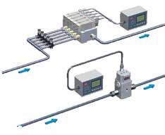
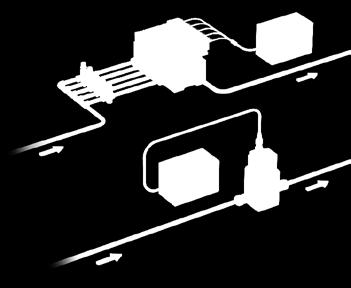
2 Series ITVH Linearity Hysteresis Repeatability ±1% F.S. or less 1% F.S. or less ±1% F.S. or less Discharge rate control Application Examples Tension control Pressure control for adhesive application High pressure electro-pneumatic regulator High pressure electro-pneumatic regulator High pressure electro-pneumatic regulator Leak tester High pressure electro-pneumatic regulator Check valve Pressure switch PET bottle molding machine (for remote control of high pressure regulator) High pressure electro-pneumatic regulator High pressure regulator (Air operated) Multi-stage control to analog control High pressure electro-pneumatic regulator Straight type Right angle type L-bracket 1 Flat bracket
3 435 psi (3.0 MPa) Maximum Supply Pressure High Pressure Electro-Pneumatic Regulator Variation Map Series 435 psi (3.0 MPa) Maximum Supply Pressure High Pressure Electro-Pneumatic Regulator New Series ITVH Model ITVH2020 Max. supply pressure Set pressure range psi [3.0 MPa] 29 psi [0.2 MPa] 290 psi [2.0 MPa] Port size Maximum flow rate 1/4 3/8 106 scfm [3000 L/min (ANR)] ( ) Supply pressure: 435 psi (3.0 MPa) Set pressure: 145 psi (1.0 MPa) Compact Electro-Pneumatic Regulator Series ITV0000 ITV001 ITV003 ITV psi [0.001MPa] 29 psi [0.2 MPa] 15 psi [0.1MPa] 0.15 psi [0.001MPa] 145 psi [1.0MPa] 73 psi [0.5MPa] 0.15 psi [0.001MPa] 145 psi [1.0MPa] 131 psi [0.9MPa] Built-in One-touch fittings ø4 ø5/ scfm [6 L/min (ANR)] ( ) Supply pressure: 145 psi (1.0 MPa) Set pressure: 87 psi (0.6 MPa) Electro-Pneumatic Regulator Series ITV1000 ITV101 ITV103 ITV psi [0.2 MPa] 15 psi [0.1MPa] 145 psi [1.0MPa] 73 psi [0.5MPa] 145 psi [1.0MPa] 131 psi [0.9MPa] 1/8 1/ scfm [200 L/min (ANR)] ( ) Supply pressure: 145 psi (1.0 MPa) Set pressure: 87 psi (0.6 MPa) For details, refer to the WEB catalog or Best Pneumatics Electro-Pneumatic Regulator Series ITV2000 ITV201 ITV203 ITV psi [0.2 MPa] 15psi [0.1MPa] 145 psi [1.0MPa] 73 psi [0.5MPa] 145 psi [1.0MPa] 131 psi [0.9MPa] 1/4 3/ scfm [1500 L/min (ANR)] ( ) Supply pressure: 145 psi (1.0 MPa) Set pressure: 87 psi (0.6 MPa) Page 803 Electro-Pneumatic Regulator Series ITV3000 ITV301 ITV303 ITV psi [0.2 MPa] 15 psi [0.1MPa] 145 psi [1.0MPa] 73 psi [0.5MPa] 145 psi [1.0MPa] 131 psi [0.9MPa] 1/4 3/8 1/2 141 scfm [4000 L/min (ANR)] ( ) Supply pressure: 145 psi (1.0 MPa) Set pressure: 87 psi (0.6 MPa) 5.0 MPa Maximum Supply Pressure High Pressure Electro-Pneumatic Regulator Series ITVX 725 psi (5.0 MPa) 1.5 psi [0.01MPa] ITVX psi 3/8 [3.0MPa] 106 scfm [3000 L/min (ANR)] ( ) Supply pressure: 725 psi (5.0 MPa) Set pressure: 435 psi (3.0 MPa) For details, refer to the WEB catalog or Best Pneumatics Page 863 The outlet of the ITVX series is released to the atmosphere for blowing 2
4 435 psi (3.0 MPa) Maximum Supply Pressure High Pressure Electro-Pneumatic Regulator Series ITVH2000 RoHS How to Order ITVH S Set pressure range 2 29 to 290psi (0.2 to 2.0 MPa) Power supply voltage 0 24 VDC Input signal 0 Current type 4 to 20 ma DC 1 Current type 0 to 20 ma DC 2 Voltage type 0 to 5 VDC 3 Voltage type 0 to 10 VDC 40 4 points preset input type S Pressure display unit Nil MPa 2 Note) kgf/cm 2 3 bar 4 Note) psi Note) Under Japan's new Measurement Act, this is only for overseas sales (SI units are to be used inside Japan). Cable connector type Straight type 3 m Monitor output Nil None (Preset input only) 1 Analog output 1 to 5 VDC 2 Switch output/npn output 3 Switch output/pnp output 4 Analog output 4 to 20 ma DC (Sink type) L N Right angle type 3 m Without cable connector Pipe thread type Nil Rc N NPT F G Note) Note) Complies with ISO (2007). Bracket Nil Without bracket Flat bracket Port size 2 1/4 3 3/8 Note) EXH port: 1/4 Built-in regulator EXH port: M5 Solenoid valve EXH port: M5 B L-bracket C Bracket is included. 3
![435 psi (3.0 MPa) Maximum Supply Pressure High Pressure Electro-Pneumatic Regulator Series ITVH2000 Standard Specifications Symbol Output pressure psi [MPa] 290 [2] This range is outside 29 [0.](/docs-images/76/74458264/images/5-0.jpg "2] of the control (output). 0 0 100 Input signal [% F.S.] Fig. 1. Input/output characteristics chart Model ITVH2000 Minimum supply pressure Whichever is higher: 73 psi (0.")
 Power supply Voltage 24 VDC ±10% Current consumption 0.")
5 435 psi (3.0 MPa) Maximum Supply Pressure High Pressure Electro-Pneumatic Regulator Series ITVH2000 Standard Specifications Symbol Output pressure psi [MPa] 290 [2] This range is outside 29 [0.2] of the control (output) Input signal [% F.S.] Fig. 1. Input/output characteristics chart Model ITVH2000 Minimum supply pressure Whichever is higher: 73 psi (0.5 MPa) or the set pressure + 29 psi (0.2 MPa) Maximum supply pressure 435 psi (3.0 MPa) Set pressure range Note 1) 29 to 290 psi (0.2 to 2.0 MPa) Power supply Voltage 24 VDC ±10% Current consumption 0.12 A or less Current type Note 2) 4 to 20 ma DC, 0 to 20 ma DC (Sink type) Input signal Voltage type 0 to 5 VDC, 0 to 10 VDC Preset input type 4 points (Negative common) Current type 500 Ω or less Input Voltage type 6.0 to 6.5 kω (at 77 F [25 C]) impedance Preset input type Approx. 4.7 kω Note 3) Output signal (Monitor output) Analog output Switch output 1 to 5 VDC Output impedance: 1 kω or more Output accuracy: ±6% F.S. or less 4 to 20 ma (Sink type) Output impedance: 250 Ω or less Output accuracy: ±6% F.S. or less NPN open collector output: Max. 30 V, 80 ma Hysteresis: ±3% F.S. Self-diagnosis: ±5% F.S. or less PNP open collector output: Max. 80 ma Hysteresis: ±3% F.S. Self-diagnosis: ±5% F.S. or less ±1% F.S. or less 1% F.S. or less ±1% F.S. or less ±1% F.S. or less ±0.12% F.S. or less/ C ±2% F.S. or less ±1 digit Linearity Hysteresis Repeatability Sensitivity Temperature characteristics Output pressure Accuracy display Minimum unit Note 4) MPa: 0.01, kgf/cm 2 : 0.1, bar: 0.1, psi: 1 Ambient and fluid temperature 32 to 122 F (0 to 50 C) (No condensation) Weight Approx. 630 g (without options) Note 1) Refer to Figure 1 for the relationship between set pressure and input signal. Note 2) 2-wire type 4 to 20 ma is not available. Power supply voltage 24 VDC is required. Note 3) Select either analog output or switch output. Further, when switch output is selected, select either NPN output or PNP output. When measuring analog output of 1 to 5 VDC with a load impedance less than 100 k Ω, the analog output may not obtain the output accuracy of ±6% F.S. or less. Note 4) Adjustment of numerical values such as the zero/span adjustment is set based on the minimum units for output pressure display. Note that the unit cannot be changed. Note 5) The above characteristics are confined to the static state. When air is consumed on the output side, the pressure may fluctuate. Note 6) This product is not certified by Japan's High Pressure Gas Safety Act. 4
6 Series ITVH2000 Accessories (Option)/Part No. Description Part no. Flat bracket assembly (including mounting screws) P L-bracket assembly (including mounting screws) P Power cable connector Straight type 3 m P Right angle type 3 m P Straight type cable connector Right angle type cable connector L-bracket Flat bracket Dimensions Flat bracket Mounting screw for the body Mounting screw for the body L-bracket Straight type cable connector Right angle type cable connector (mm) Flat bracket 100 L-bracket (8.5) ø x R Working Principle When the input signal rises, the air supply solenoid valve q turns ON, and the exhaust solenoid valve w turns OFF. Therefore, supply pressure regulated by a built-in regulator e passes through the air supply solenoid valve q and is applied to the pilot chamber r. The pressure in the pilot chamber r increases and operates on the upper surface of the diaphragm t. As a result, the air supply valve y linked to the diaphragm t opens, and a portion of the supply pressure becomes output pressure. This output pressure feeds back to the control circuit i via the pressure sensor u. Here, a correct operation functions until the output pressure is proportional to the input signal, making it possible to always obtain output pressure proportional to the input signal. Power supply Input signal q Air supply solenoid valve e Built-in regulator Built-in regulator EXH t Diaphragm Working Principle Diagram Pressure display i Control circuit P Output signal w Exhaust solenoid valve Solenoid valve EXH u Pressure sensor r Pilot chamber y Air supply valve SUP EXH OUT 5
7 Series ITVH psi (3.0 MPa) Maximum Supply Pressure High Pressure Electro-Pneumatic Regulator Series ITVH2000 Linearity Set pressure psi [MPa] 363 [2.5] 290 [2.0] 218 [1.5] 145 [1.0] 73 [0.5] Input signal [% F.S.] Hysteresis Output deviation factor [% F.S.] Out Return Input signal [% F.S.] Repeatability 1.0 Pressure Characteristics 1.0 Set pressure: 145 psi [1.0 MPa] Output deviation factor [% F.S.] Input signal [% F.S.] Output deviation factor [% F.S.] 0.5 Set point Return 0.0 Out [1.0] 218 [1.5] 290 [2.0] 363 [2.5 ] 435 [3.0] 508 [3.5] Supply pressure psi [MPa] Flow-rate Characteristics Set pressure psi [MPa] 145 [1.0] 131 [0.9] Supply pressure: 145 psi [1.0 MPa] 116 [0.8] 102 [0.7] 87 [0.6] 73 [0.5] 58 [0.4] 44 [0.3] 29 [0.2] 15 [0.1] [500] 35 [1000] 53 [1500] 71 [2000] Flow rate scfm [L/min (ANR)] Relief Characteristics Set pressure psi [MPa] Supply pressure: 145 psi [1.0 MPa] 145 [1.0] 131 [0.9] 116 [0.8] 102 [0.7] 87 [0.6] 73 [0.5] 58 [0.4] 44 [0.3] 29 [0.2] 15 [0.1] [100] 7 [200] 11 [300] 14 [400] 17 [500] 21 [600] Flow rate scfm [L/min (ANR)] 6
8 Series ITVH2000 Dimensions (mm) Do not turn the right angle type cable connector. It does not rotate and is limited to only one entry direction. Right angle type cable connector 3 m Straight type cable connector 3 m (33) Setting part M5 x 0.8 Built-in regulator EXH M12 x 1 Cable connection thread (Plug type) Digital pressure display Built-in regulator EXH 1/4 (Rc, NPT) Port 3 (Exhaust port) Port 3 (Exhaust port) Port 1 (Supply port) 10 M4 x 0.7 depth 8 F.G. Solenoid valve EXH Port 2 (Output port) M5 x 0.8 Solenoid valve EXH 8 Breathing hole /4, 3/8 (Rc, NPT) Port 1 (Supply port) 1/4, 3/8 (Rc, NPT) Port 2 (Output port) 36 4 x M5 x 0.8 depth 11 Bracket mounting hole 36 Do not block three EXH ports on this product. With flat bracket x 7 G thread G1/4 20 depth, depth of counterbore 1.5 Port 3 (Exhaust port) G1/4 20 depth, depth of counterbore 1.5 Port 1 (Supply port), Port 2 (Output port) G3/8 23 depth, depth of counterbore 2 Port 1 (Supply port), Port 2 (Output port) Flat bracket 1/4 (Rc, NPT) Port 3 (Exhaust port) 1/4, 3/8 (Rc, NPT) Port 2 (Output port) 1/4 (Rc, NPT) Port 3 (Exhaust port) 1/4, 3/8 (Rc, NPT) Port 2 (Output port) 24 L-bracket With L-bracket 24 7 (8.5)
9 Series ITVH2000 Specific Product Precautions 1 Be sure to read this before handling. Refer to the back cover for Safety Instructions. For F.R.L. Precautions, refer to Handling Precautions for SMC Products and the Operation Manual on SMC website, Warning Expose approx. 2 threads Piping 1. Screw piping together with the recommended proper torque while holding the side with the female threads. Looseness or faulty sealing will occur if tightening torque is insufficient, while thread damage will result if the torque is excessive. Furthermore, if the side with the female threads is not held while tightening, excessive force will be applied directly to piping brackets etc., causing damage or other problems. Connection thread Recommended proper torque lbf ft [N m] M5 1.1 to 1.5 (1.5 to 2) 1/4 5.9 to 8.9 (8 to 12) 3/8 11 to 15 (15 to 20) 2. Do not allow twisting or bending moment to be applied other than the weight of the equipment. Provide separate support for external piping, as damage may otherwise occur. 3. Since excessive moment loads and the propagation of vibrations, etc. can easily result from inflexible piping made of materials such as steel, avoid these problems by using flexible tubing for intermediate connections. 4. Piping port indication When connecting piping to a product, refer to the Operation Manual to avoid mistakes regarding the port. Port 1: Supply port Port 2: Output port Port 3: Exhaust port 5. Exhaust port Do not reduce the diameter of port 3 (the exhaust port), EXH port of solenoid valve, or EXH port of built-in regulator too much or block it. It will lead to an operation failure. 1. Preparation before piping Before piping is connected, it should be thoroughly blown out with air (flushing) or washed to remove chips, cutting oil and other debris from inside the pipe. 2. Wrapping of sealant tape When screwing together pipes and fittings, etc., be certain that chips from the pipe threads and sealing material do not get inside the piping. Also, when sealant tape is used, leave 1.5 to 2 thread ridges exposed at the end of the threads. Wrapping direction Sealant tape Warning Warning Operating Environment 1. Do not operate in locations having an atmosphere of corrosive gases, chemicals, sea water, or where there will be contact with the same. 1. In locations where the body is exposed to water, steam, dust, etc., there is a possibility that moisture or dust could enter the body through the EXH port, solenoid valve EXH port and/or built-in regulator EXH port, thereby causing problems. 2. Do not operate in locations where vibration or impact occurs. 3. In locations which receive direct sunlight, provide a protective cover etc. 4. In locations near heat sources, block off any radiated heat. 5. Employ suitable protective measures in locations where there is contact with water droplets, oil or welding spatter, etc. Fluid Supply 1. Compressed air or nitrogen can be used as a fluid. 2. Do not use compressed air which includes chemicals, synthetic oils containing organic solvents, salt, or corrosive gases, etc., as this can cause damage or malfunction. 1. This product does not have a filtering function. Install an air filter on the supply side close to the product. Select an air filter with a filtration degree of 5 µm or finer. 2. Compressed air containing large amounts of drainage can cause a malfunction of this product and other pneumatic equipment. As a countermeasure, install an aftercooler, air dryer or water separator, etc. 3. If large amounts of carbon dust are generated by the compressor, it can accumulate inside this product and cause a malfunction (air leakage etc.). For details on the above compressed air quality, refer to Air Preparation Equipment Model Selection Guide in the Best Pneumatics No. 5 catalog. 8
10 Series ITVH2000 Specific Product Precautions 2 Be sure to read this before handling. Refer to the back cover for Safety Instructions. For F.R.L. Precautions, refer to Handling Precautions for SMC Products and the Operation Manual on SMC website, Handling 1. Do not use a lubricator on the supply side of this product, as this can cause a malfunction. 2. If electric power is shut off while pressure is being applied, pressure will be retained on the output side. However, this output pressure is held only temporarily and is not guaranteed. If exhausting of this pressure is desired, shut off the power after reducing the set pressure, and discharge the air using a residual pressure exhaust valve etc. 3. If power to this product is cut off due to a power failure etc. when it is in a controlled state, output pressure will be retained temporarily. Handle carefully when operating with output pressure released to the atmosphere, as air will continue to flow out. 4. If supply pressure to this product is interrupted while the power is still on, the internal solenoid valve will continue to operate and a humming noise may be generated. Since the life of the product may be shortened, shut off the power supply also when supply pressure is shut off. 5. Do not block three EXH ports on this product. 6. This product does not have a shutoff valve function. If air pressure is supplied without electric power being applied, output pressure may increase to the pressure equivalent of the supply pressure. Due to product construction, a very small amount of air is discharged from the exhaust port when output pressure is generated. Operate the system to shut off the supply pressure when not operating the product. 7. The product is adjusted to each specification at the time of shipment from the factory. Do not perform unnecessary disassembly or removal of parts as it will cause failure. 8. The optional cable connector is a 4-core wire type. When the monitor output (analog output or switch output) is not being used, keep it from touching the other wires as this can cause a malfunction. 9. Do not turn the right angle type cable connector. It does not rotate and is limited to only one entry direction. 10. Take the following steps to avoid a malfunction due to noise. 1) Remove power supply noise during operation by installing a line filter etc. in the AC power line. 2) For avoiding the influence of noise or static electricity, install this product and its wiring as far as possible from strong electric fields such as those of motors and power lines, etc. 3) Be sure to implement protective measures against load surge for induction loads (solenoid valves, relays, etc.). 11. For details on the handling of this product, refer to the Operation Manual which is included with the product. +24 V Output power 0 V Control/Input power +24 V Design/Selection 1. The direct-current power supply to combine should be UL authorized power supply. 1) Limited voltage current circuit in accordance with UL508. A circuit in which power is supplied by the secondary coil of a transformer that meets the following conditions. Maximum voltage (with no load): 30 [Vrms] (42.4 [V peak]) or less Maximum current: 1. 8 [A] or less (including when short circuited) 2. Limited by circuit protector (such as fuse) with the following ratings No load voltage [V peak] Max. current rating [A] 0 to 20 [V] Over 20 [V] to 30 [V] Peak voltage 2) A circuit using max. 30 [Vrms] or less (42.4 [V peak]), which is powered by UL1310 or UL1585 compatible Class-2 power supply. 2. Operate these products only within the specified voltage. Using voltages beyond the specified levels could cause faults or malfunctions. 3. Use 0 V as the baseline for the power supplied to this product for output, control and input. +24 V Output power 0 V Control/Input power 24 V 4. Each product needs to be powered by one power supply unit. The wiring of this product has the same common between the GND for power and the signals; there is a possibility that a wrong current occurs and prevents a proper operation if one power supply unit controls multiple electro-pneumatic regulators. 5. Please contact SMC for the usage when the downstream side is released to atmosphere. This product is a pressure controller. The downstream side being released to atmosphere makes the inlet valve fully open, allowing a large amount of atmosphere flow into the body. Please contact SMC for the appropriate usage when you use the product under such condition since the product may not meet the specification or the life of the product may be shortened. 9
11 Series ITVH2000 Specific Product Precautions 3 Be sure to read this before handling. Refer to the back cover for Safety Instructions. For F.R.L. Precautions, refer to Handling Precautions for SMC Products and the Operation Manual on SMC website, Connect the cable to the connector on the body with the wiring arranged as shown below. Proceed carefully, as incorrect wiring can cause damage. Further, use DC power with sufficient capacity and a low ripple. Body Note) 3: () 1: () 4: () 2: () Wiring F.G. (Grounding) Ground the frame ground (F.G.) terminal at the front of the main body. If the F.G. terminal port is not used, this product may not operate properly due to the noise. M4 x 0.7 depth 8 F.G. Note) The cable is also available in a right angle type. A right angle type connector is attached facing left (toward the SUP port). Do not attempt to rotate, as the connector does not turn. Current Signal Type Voltage Signal Type 1 Power supply 2 Input signal 3 GND (COMMON) 4 Monitor output Wiring diagram Current signal type Vs A Preset Input Type 1 Power supply 2 Input signal 1 3 GND (COMMON) 4 Input signal 2 Voltage signal type Vs Vin Monitor output wiring diagram Analog output: Voltage type Analog output: Current type (Sink type) Monitor output voltage Switch output: NPN type Load Monitor output current Switch output: PNP type Load Vs : Power supply 24 VDC A : Input signal 4 to 20 ma DC 0 to 20 ma DC Vs : Power supply 24 VDC Vin : Input signal 0 to 5 VDC 0 to 10 VDC When 80 ma DC or more is applied, detecting device for over current starts activating and then emits an error signal. (Error number 5 ) 4 points preset input type Vs S1 S2 Vs: Power supply 24 VDC (Negative common) One of the preset pressures P1 through P4 is selected by the ON/OFF combination of S1 and S2. S1 OFF ON OFF ON S2 OFF OFF ON ON Preset pressure P01 P02 P03 P04 For safety reasons, it is recommended that one of the preset pressures be set to 0 MPa. Preset pressures are set based on the minimum unit for output display. MPa kgf/cm 2 bar psi
12 Safety Instructions : Warning: Danger : indicates a hazard with a low level of risk which, if not avoided, could result in minor or moderate injury. Warning indicates a hazard with a medium level of risk which, if not avoided, could result in death or serious injury. Danger indicates a hazard with a high level of risk which, if not avoided, will result in death or serious injury. These safety instructions are intended to prevent hazardous situations and/or equipment damage. These instructions indicate the level of potential hazard with the labels of, Warning or Danger. They are all important notes for safety and must be followed in addition to International Standards (ISO/IEC) 1), and other safety regulations. 1) ISO 4414: Pneumatic fluid power General rules relating to systems. ISO 4413: Hydraulic fluid power General rules relating to systems. IEC : Safety of machinery Electrical equipment of machines. (Part 1: General requirements) ISO : Manipulating industrial robots Safety. etc. Warning 1. The compatibility of the product is the responsibility of the person who designs the equipment or decides its specifications. Since the product specified here is used under various operating conditions, its compatibility with specific equipment must be decided by the person who designs the equipment or decides its specifications based on necessary analysis and test results. The expected performance and safety assurance of the equipment will be the responsibility of the person who has determined its compatibility with the product. This person should also continuously review all specifications of the product referring to its latest catalog information, with a view to giving due consideration to any possibility of equipment failure when configuring the equipment. 2. Only personnel with appropriate training should operate machinery and equipment. The product specified here may become unsafe if handled incorrectly. The assembly, operation and maintenance of machines or equipment including our products must be performed by an operator who is appropriately trained and experienced. 3. Do not service or attempt to remove product and machinery/ equipment until safety is confirmed. 1. The inspection and maintenance of machinery/equipment should only be performed after measures to prevent falling or runaway of the driven objects have been confirmed. 2. When the product is to be removed, confirm that the safety measures as mentioned above are implemented and the power from any appropriate source is cut, and read and understand the specific product precautions of all relevant products carefully. 3. Before machinery/equipment is restarted, take measures to prevent unexpected operation and malfunction. 4. Contact SMC beforehand and take special consideration of safety measures if the product is to be used in any of the following conditions. 1. Conditions and environments outside of the given specifications, or use outdoors or in a place exposed to direct sunlight. 2. Installation on equipment in conjunction with atomic energy, railways, air navigation, space, shipping, vehicles, military, medical treatment, combustion and recreation, or equipment in contact with food and beverages, emergency stop circuits, clutch and brake circuits in press applications, safety equipment or other applications unsuitable for the standard specifications described in the product catalog. 3. An application which could have negative effects on people, property, or animals requiring special safety analysis. 4. Use in an interlock circuit, which requires the provision of double interlock for possible failure by using a mechanical protective function, and periodical checks to confirm proper operation. Compliance Requirements 1. The product is provided for use in manufacturing industries. The product herein described is basically provided for peaceful use in manufacturing industries. If considering using the product in other industries, consult SMC beforehand and exchange specifications or a contract if necessary. If anything is unclear, contact your nearest sales branch. Limited warranty and Disclaimer/ Compliance Requirements The product used is subject to the following Limited warranty and Disclaimer and Compliance Requirements. Read and accept them before using the product. Limited warranty and Disclaimer 1. The warranty period of the product is 1 year in service or 1.5 years after the product is delivered, whichever is first. 2) Also, the product may have specified durability, running distance or replacement parts. Please consult your nearest sales branch. 2. For any failure or damage reported within the warranty period which is clearly our responsibility, a replacement product or necessary parts will be provided. This limited warranty applies only to our product independently, and not to any other damage incurred due to the failure of the product. 3. Prior to using SMC products, please read and understand the warranty terms and disclaimers noted in the specified catalog for the particular products. 2) Vacuum pads are excluded from this 1 year warranty. A vacuum pad is a consumable part, so it is warranted for a year after it is delivered. Also, even within the warranty period, the wear of a product due to the use of the vacuum pad or failure due to the deterioration of rubber material are not covered by the limited warranty. 1. The use of SMC products with production equipment for the manufacture of weapons of mass destruction (WMD) or any other weapon is strictly prohibited. 2. The exports of SMC products or technology from one country to another are governed by the relevant security laws and regulations of the countries involved in the transaction. Prior to the shipment of a SMC product to another country, assure that all local rules governing that export are known and followed. SMC products are not intended for use as instruments for legal metrology. Measurement instruments that SMC manufactures or sells have not been qualified by type approval tests relevant to the metrology (measurement) laws of each country. Therefore, SMC products cannot be used for business or certification ordained by the metrology (measurement) laws of each country. Safety Instructions Be sure to read Handling Precautions for SMC Products (M-E03-3) before using SMC Corporation of America, All Rights Reserved. All reasonable efforts to ensure the accuracy of the information detailed in this catalog were made at the time of publishing. However, SMC can in no way warrant the information herein contained as specifications are subject to change without notice. TP-RRD-5M
5.0 MPa Maximum Supply Pressure. New. Stepless control of air pressure proportional to an electrical signal. Series ITVX CAT.
 5.0 MPa Maximum Supply Pressure High Pressure Electro-Pneumatic Regulator This product is only for blowing gas. This product does not have sufficient pressure control for other applications (driving, sealing,
Vacuum Saving Valve Series ZP2V How to Order ZP2V A5 03 Connection thread symbol for the pad Male thread connection Symbol Thread Applicable fixed ori
 Vacuum Saving Valve Series ZP2V Model Selection Select the quantity of vacuum saving valves that can be used with one vacuum generator. Selection Conditions Work piece: No leakage and several sizes Required
Air operated valve. VGA342R Series
 Doc. No.VG300***-OMH0006-A PRODUCT NAME Air operated valve MODEL / Series / Product Number VGA342R Series Contents Safety Instructions ----------------------------------------------------------------------------
No.IL02-OM00011-A PRODUCT NAME LOCK UP VALVE. MODEL/ Series IL201 IL211
 No.IL02-OM00011-A PRODUCT NAME LOCK UP VALVE MODEL/ Series IL201 IL211 Table of Contents Instructions for your Safety 1~2 1. Summary 3 2. Specification 3 3. Operation Principle 3~4 4. Transportation and
30% (SMC comparison) Silencer. New. New. The M5 silencer is now added! The resin silencer is now a more compact size! Series AN.
 Silencer. New. New. The M5 silencer is now added! The resin silencer is now a more compact size! Series AN.") Silencer The M silencer is now added! Space saving New RoHS ctual size 6. mm mm Fingertip size The resin silencer is now a more compact size! Existing model Entire length reduced by up to 30% (SMC comparison)
Silencer The M silencer is now added! Space saving New RoHS ctual size 6. mm mm Fingertip size The resin silencer is now a more compact size! Existing model Entire length reduced by up to 30% (SMC comparison)
Doc. No.SYJ300-OMO0002-A. Air Operated Valve PRODUCT NAME. SYJA300 / SYJ3000 Series MODEL/ Series
 Doc. Air Operated Valve PRODUCT NAME SYJA300 / SYJ3000 Series MODEL/ Series Contents Safety Instructions ---------------------------------------------------------------------------- 2,3 Precautions on
Industrial Filter. FGD series
 1/8 P r o d u c t N a m e Industrial Filter Model/ Series/ Product Number FGD series FGD - - - Material Accessory Element length Element Port size Contents 2/8 Safety Instructions 3 Safety Instructions
Pressure Relief 3 Port Valve New. Sonic Conductance 45% With the indicator window Step1. With locking holes
 Conforming to OSHA Standard Pressure Relief Port Valve New RoHS with Locking Holes Weight Max. 60% Lighter Sonic Conductance 5% C[dm/s bar] VHS0 Max. Energy Saving Up Safety Measure Zero blow-by of the
Series IRV1000/2000/3000
 CAT.ES60-16 A Regulator Series /2000/3000 Allows adjustment of vacuum line pressure Regulator Series /2000/3000 3 sizes offered in the series Variations have been expanded to three sizes from only one
Related Products: Auto Drain Valve. Model/Specifications. Model
 Related Products: Auto Drain Valve /600 Drainage is automatically discharged in a reliable manner, without requiring human operators. Highly resistant to dust and corrosion, operates reliably, and a bowl
IR1000-A IR1010-A IR1020-A
 Document No. IR -OMT0020 PRODUCT NAME Precision Regulator MODEL / Series / Product Number IR1000-A IR1010-A IR1020-A Contents Safety Instructions 1 to 5 1. Application 6 2. Specifications 6 3. Construction
Series ITVH CAT.EUS60-23A-UK
 3.0 MPa Maximum Supply Pressure High Pressure Electro-Pneumatic Regulator RoHS Maximum supply pressure Set pressure range Stability 3.0 MPa 0.2 to 2.0 MPa Stepless control of air pressure up to 2.0 MPa
Series AMJ. Drain Separator for Vacuum
 CAT.E 827- Drain Separator for Vacuum Remove water droplets from air by simply installing in vacuum equipment connection lines. Effective for removing water droplets from the air sucked into vacuum pumps
PRODUCT NAME. Main Line Filter. MODEL / Series / Product Number
 PRODUCT NAME Main Line Filter MODEL / Series / Product Number AFF75A-20 / AFF75A-20X13 AFF125A-30 / AFF125A-30X13 AFF150A-40 / AFF150A-40X13 AFF220A-40 / AFF220A-40X13 This operation manual is for model
5 Port Air Operated Valve
 Doc. No. PRODUCT NAME 5 Port Air Operated Valve MODEL / Series / Product Number VPA4 50/4 70/VVPA4 0 Series Contents Safety Instructions ----------------------------------------------------------------------------
How to Order. Body size. Pressure: 2 MPa. Pressure increase ratio 0 Twice. Symbol. Thread type. Body size
 Booster Regulator Series VBA How to Order VBA 0 series VBA 0 0 Body size /4 Pressure: MPa Pressure increase ratio 0 Twice Thread type Symbol F Thread type G Port size Symbol Port size 0 /4 Symbol VBA0-0
Membrane Air Dryer. IDG1-C06 Series IDG1-C06-P Series
 No.AMX-OM-R001 P r o d u c t N a m e Membrane Air Dryer Model / Series / Product Number IDG1-C06 Series IDG1-C06-P Series Contents Safety Instructions 2 Handling Precautions 4 Maintenance and Inspection
Lightweight and Compact Type Floating Joint
 Document No. J -OMT0084 P r o d u c t N a m e Lightweight and Compact Type Floating Joint Model / Series / Product Number JT series Contents 1. Safety Instructions--------------------------------------------
Digital electro-pneumatic regulators Series ER100
 CATALOGUE > Release 8.2 Digital electro-pneumatic regulators Series ER100 TREATMENT > Digital electro-pneumatic regulators Series ER100 Port G1/4» Compact design» Digital display» Analog and digital input»
Filter-Regulator-Lubricator
 Filter-Regulator-Lubricator 1/2" NPT Inlet/Outlet Ports PD16.19 July, 2016 Machine Parts & Operating Instructions Save This Document and Educate All Personnel WARNING Always follow the safety instructions
COMMON PRECAUTIONS Data Sheet - Be Sure To Read Before Handling Page 1 of 6
 COMMON PRECAUTIONS Page 1 of 6 These safety instructions are intended to prevent a hazardous situation and/or equipment damage. These instructions indicate the level of potential hazard by labels of "Caution",
1.0. ISE70/71 Series CAT.ES A. MPa/1.6 MPa. 3-Screen Display High-Precision Digital Pressure Switch. Angled display.
 3-Screen Display High-Precision Digital Pressure Switch For Air 1.0 ISE70 ISE71 MPa/1.6 MPa RoHS IP67 It is possible to change the settings while checking the measured value. Main screen Measured value
2/ Port G1/4
 CATALOGUE > Release 8.8 > Series ER100 digital electro-pneumatic regulators Series ER100 digital electro-pneumatic regulators Port G1/4 Compact design Digital display Analog and digital input Programmable
SeriesTRBU. Flame Resistant (Equivalent to UL-94 Standard V-0) FR Double Layer Polyurethane Tubing
 FR Double Layer Polyurethane Tubing") CAT.E521- A Flame Resistant (Equivalent to UL-94 Standard V-0) FR Double Layer Polyurethane Tubing SeriesTRBU For general air and water piping in environments with sparks from spot welding, etc. Double
CAT.E521- A Flame Resistant (Equivalent to UL-94 Standard V-0) FR Double Layer Polyurethane Tubing SeriesTRBU For general air and water piping in environments with sparks from spot welding, etc. Double
Pressure Sensor PSE53#
 PRODUCT NAME Pressure Sensor MODEL / Series / Product Number PSE53# Table of Contents Safety Instructions 2 Model Identification and how to order 8 Definition and terminology 8 Mounting and Installation
Regulator for 2 MPa ARX 20. How to Order. Bracket. Pressure gauge. Port size 1/8 1/4. Panel nut
 Regulator for 2 MPa RX 2 How to Order RX2 1 Regulator 1 Regulating pressure.5 to.85mpa {.51 to 8.7kgf/cm²}.5 to.3mpa {.51 to 3.1kgf/cm²} Thread type Nil N F Rc(PT) NPT (PF) Port size 1 2 ccessories/options
PVC Quick Drain Valve
 PVC Quick Drain Valve LVW Series Complies to JIS standard for polyvinyl chloride piping (JIS K 6742) Applicable fluids: Deionized water, Chemical liquids Application Example Cleaning Equipment Process
kpa or less 5.0. Compressed Air Preparation Filter. AFF/AM/AMD Series CAT.ES30-17B. 1 μm (Current model: 3 μm) 20% 60% 52% 160 mm.
 20% 60% 52% 160 mm.") Compressed Air Preparation Filter Compressed Air Purity Class ISO 573 Main Line Filter Series Mist Separator Series 1 μm.1 μm Water droplet removal Oil mist separation and removal Micro Mist Separator
Compressed Air Preparation Filter Compressed Air Purity Class ISO 573 Main Line Filter Series Mist Separator Series 1 μm.1 μm Water droplet removal Oil mist separation and removal Micro Mist Separator
Pressure Sensor PSE54#
 PRODUCT NAME Pressure Sensor MODEL / Series / Product Number PSE54# Table of Contents Safety Instructions 2 Model Identification and how to order 8 Definition and terminology 8 Mounting and Installation
reduces flow setting time and setting errors!
 Speed Controller with Indicator Numerical indication of handle rotation for flow rate reduces flow setting time and setting errors! New RoHS Indicator window Size Size or larger Indicator window Number
Pilot Check Valve: Metal Body Type
 INFORMATION Pilot Check Valve: Metal Body Type The use of a metal body improves strength and environmental resistance. Temporary intermediate stops are possible. *1 *1 Precise intermediate stops are not
Doc. No.VFR3000-OMH0005-B. 5 Port Air Operated Valve PRODUCT NAME. VFRA3000, 4000 Series MODEL/ Series
 Doc. No. 5 Port Air Operated Valve PRODUCT NAME VFRA3000, 4000 Series MODEL/ Series Contents Safety Instructions ---------------------------------------------------------------------------- 2, 3 Precautions
5 Port Solenoid Valve
 Doc. No. PRODUCT NAME 5 Port Solenoid Valve MODEL / Series / Product Number VP4*50/VP4*70/VVP4*0 Series Contents Safety Instructions ---------------------------------------------------------------------------
INSTALLATION & MAINTENANCE INSTRUCTIONS
 DESCRIPTION / IDENTIFICATION The QBX series valve uses Proportion-Air closed loop technology for Pressure control. It gives an output pressure proportional to an electrical command signal input. The QB1X
Series SFD. Clean Air Filter. Variations. Made to Order. Type. Cartridge (replaceable element) Disposable (non-replaceable element) Up to 100
 Disposable (non-replaceable element) Up to 100") Clean Air Filter Variations SFD SFD SFD SFD Made to Order Type Disposable (non-replaceable element) Cartridge (replaceable element) Flow rate L/min (ANR) (at inlet pressure.7 MPa) Up to 6 Up to 8 Up to
Clean Air Filter Variations SFD SFD SFD SFD Made to Order Type Disposable (non-replaceable element) Cartridge (replaceable element) Flow rate L/min (ANR) (at inlet pressure.7 MPa) Up to 6 Up to 8 Up to
New Product. Air Consumption 70% Down. Precision Regulator Air Saving Type. RPE Series PRECISION REGULATOR RPE SERIES CC-1072A
 Air Consumption 70% Down New Product Precision Regulator Air Saving Type RPE Series PRECISION REGULATOR RPE SERIES Large Air Saving CC-1072A Air Consumption 70% Down. New Type Eco-friendly Precision Regulator
INSTALLATION & MAINTENANCE INSTRUCTIONS DESCRIPTION SPECIFICATIONS. CE (EMC) Compliant
 Compliant") INSTALLATION & MAINTENANCE INSTRUCTIONS DESCRIPTION The QB3 is a closed loop pressure regulator consisting of two solenoid valves, internal pressure transducer, and electronic controls mounted to an integrated
INSTALLATION & MAINTENANCE INSTRUCTIONS DESCRIPTION The QB3 is a closed loop pressure regulator consisting of two solenoid valves, internal pressure transducer, and electronic controls mounted to an integrated
Operation Manual Air Saver Unit ASV5000 Series
 9IM-V066-b Operation Manual Air Saver Unit ASV5000 Series Thank you for your choice of Kuroda Pneumatics LTDs product on this time. Please read this operation manual carefully and use the product correctly.
VACUUM REGULATORS CONTENTS
 CAD drawing data catalog is available. ACCESSORIES GENERAL CATALOG AIR TREATMENT, AUXILIARY, VACUUM, AND FLUORORESIN PRODUCTS CONTENTS Small Regulators Features 759 Specifications, Order Codes, Flow Rate
E8AA. Pressure Sensor of Stainless Steel Construction Is Ideal for a Wide Range of Applications. Pressure Sensor (Stainless Steel Diaphragm)
") Pressure Sensor (Stainless Steel Diaphragm) CSM DS_E_3_1 Pressure Sensor of Stainless Steel Construction Is Ideal for a Wide Range of Applications Incorporates double diaphragms consisting of SUS316L stainless
Pressure Sensor (Stainless Steel Diaphragm) CSM DS_E_3_1 Pressure Sensor of Stainless Steel Construction Is Ideal for a Wide Range of Applications Incorporates double diaphragms consisting of SUS316L stainless
Precision Regulator IR3120
 Doc. no. IR30-OM00004-F PRODUCT NAME Precision Regulator MODEL/ Series IR3120 Contents Safety Instructions 2~3 1. Specifications 4~5 2. Construction and operation principle 6 3. How to order 7 4. Marking
Pressure Sensor for General Fluids PSE56#
 PRODUCT NAME Pressure Sensor for General Fluids MODEL / Series / Product Number PSE56# Table of Contents Safety Instructions 2 Model Identification and How to Order 8 Definition and terminology 8 Mounting
Moisture Control Tube
 Moisture Control Tube (Moiscon) Prevents! Prevents condensation in piping for small cylinders/air grippers. Diffuses water vapor in the piping to the outside! vapor vapor vapor Moisture control tube General
Precision Regulator. Series Model Regulating pressure range Port size Page
 Precision Regulator Series // Basic Type Air Operated Type Series Model Regulating pressure range Page Series Series Series Series Series.5 to MPa. to MPa. to.8 MPa /8 55.5 to MPa. to MPa /4 55. to.8 MPa.
Parallel Seal Type Slit Valve
 For 00 mm wafer Parallel Seal Type Slit Valve Long service life million cycles (at ordinary temperature) Maintenance Replaceable bellows Top accessible (Made to order) Air saving Made to order Air consumption
Filter-Regulator-Lubricator
 Models: 10671-1/2" NPT Filter 10673-1/2" NPT Regulator 10675-1/2" NPT Lubricator 10677-1/2" NPT Filter-Regulator 10679-1/2" NPT Regulator-Lubricator 10681-1/2" NPT Filter-Regulator-Lubricator Parts Page
Precision Regulator. IR1000/2000/3000 Series ARJ ARX AMR ARM ARP IR -A IR IRV VEX SRH SRP SRF ITV IC ITVH ITVX PVQ VY1 AP100.
 Precision Regulator //3 Series Basic Type Air Operated Type Series Model Set pressure range Port size Page Series Series 3 Series 3 3 3 Series 3 Series 3.5 to MPa. to MPa. to.8 MPa /8 8.5 to MPa. to MPa.
Direct Operated Precision Regulator Modular Style. Standard Specifications
 1 Direct Operated Precision Regulator Modular Style Series P3 Courtesy of Steven Engineering, Inc.-23 Ryan Way, South San Francisco, CA 948-637-Main Office: (65) 588-92-Outside Local Area: (8) 258-92-www.stevenengineering.com
Multistage Ejector Series ZL
 Multistage Ejector Series. Energy-saving, large flow rate, 3 stage diffuser construction Suction flow rate increased 5% and air consumption reduced % with 3 stage diffuser construction (ersus ø.3, one
Multistage Ejector Series ZL
 Multistage Ejector Series. Energy-saving, large flow rate, 3 stage diffuser construction Suction flow rate increased 5% and air consumption reduced % with 3 stage diffuser construction (ersus ø.3, one
Power Valve: Precision Regulator. High precision, large capacity relief regulator
 Power Valve: Precision Regulator Series VEX High precision, large capacity relief regulator port large exhaust capacity pressure reducing valve which utilizes a nozzle flapper mechanism available as air
F.R.L. Units Precautions 1 Be sure to read this before handling.
 Precautions 1 1. Confirm the specifications. Products represented in this catalog are designed only for use in compressed air systems (including vacuum). Do not operate at pressures or temperatures, etc.,
Process Pump PB1000A
 PAB-OM-N002 PRODUCT NAME Process Pump MODEL / Series / Product Number PB1000A Foreword Thank you for purchasing SMC s process pump. This manual is intended to explain the operation of the product. This
Low Friction Cylinders
 CAT.ES-15 C Low Friction Cylinders Metal Seal Type ø30, ø0 newly added Compact Low Friction Cylinder Series MQQ Bore size Operating pressure range Actuation speed (MPa) (mm/s) Series MQQT Standard type
Series AS-FPQ/AS-FPG. Speed Controller with One-touch Fitting for Clean Room. Speed controllers for clean room use
 CAT.ES20-19 A Speed Controller with One-touch Fitting for Clean Room Series AS-FPQ/AS-FPG Series AS-FPG Series AS-FPQ Speed controllers for clean room use AS-FPQ: Brass (electroless nickel plated) and
Maximum 0.85 MPa pressure setting Long-life, high flow perfect for balancer applications
 Outstanding performance in extremely low pressure and low pressure ranges from 0.003 to. Realizing high performance, energy saving, and compact size. Realize precise pressure control in a pressure range
Booster Regulator/Air Tank
 Booster Regulator/Air Tank Increase factory air pressure by up to 4 times! Air-only operation requires no power supply, reduces heat generation, and Boost pressure allows easy installation. NEW Renewed
Technical Specifications
 No. : PS##-OMG0006 Technical Specifications PSE560 series Contents Safety.P2 Model Indication Method.P6 Specification.P7 Full View with Dimensions.P8 Installation.P9 Examples of Internal Circuit and Wiring.P10-1
Port size. Model Screw-in ZFA10 1/8 ZFA20 1/4 ZFB10 ZFB20 ZFB30 ZFB40 ZFC5 ZFC7
 Air Suction Filter Series ZF Prevent from occurring vacuum equipment trouble due to solid foreign objects. Series Features Port size Model Screw-in for One-touch fittings Air flow Note) [L/min(ANR)] Filtration
Components for air preparation and pressure adjustment. OUT port position ( ) connected Rear side. of IN port. Air tank. directly.
 connected Rear side. of IN port. Air tank. directly.") Components preparation and pressure adjustment ABP Overview ABP is a component that enables boosting by s only up to twice primary pressure (.0MPa max.) in combination with using air tank but not using
Components preparation and pressure adjustment ABP Overview ABP is a component that enables boosting by s only up to twice primary pressure (.0MPa max.) in combination with using air tank but not using
QBS Electronic Pressure Regulator
 INSTALLATION AND MAINTENANCE INSTRUCTIONS DESCRIPTION / IDENTIFICATION The QBS stainless steel series is an electronically controlled pressure regulator. The QBS controls the pressure on its output port
Low torque Metal seal type Rotary joint
 CAT.E0- A Low torque Metal seal type Rotary joint Long Life 0. to billion rotations Under SMC s life test conditions. Flexible Coupling Fixed (Body) Low rotational torque 0.00 to 0.0 N.m or less Rotary
Series ZFC. Air Suction Filter In-line Type with One-touch Fittings
 CAT.E832- A Air Suction Filter In-line Type with One-touch Fittings Series ZFC An in-line type air suction filter that prevents trouble in vacuum equipment due to contaminants in the air IN/OUT straight
10 switches simultaneously. The settings of the master sensor (source of copy) can be copied to the slave sensors. Reducing setting labor
 can be copied to the slave sensors. Reducing setting labor") 2-Color Display High-Precision Digital Pressure Switch Series ZSEA(F)/EA ZSE E RoHS New IP65 ZSE E ZSE0 E0 M8 connector type E70 ZSE E E Applicable Air, Non-corrosive gas, Non-flammable gas fluid Can copy
2-Color Display High-Precision Digital Pressure Switch Series ZSEA(F)/EA ZSE E RoHS New IP65 ZSE E ZSE0 E0 M8 connector type E70 ZSE E E Applicable Air, Non-corrosive gas, Non-flammable gas fluid Can copy
Process Pump. Series PAF3000/Series PAF5000
 Process Pump Series 3/Series The excellent corrosion resistance is achieved due to the new PFA wetted material construction! PPS/PFA dual construction, withstand pressure and heat cycle performance have
Pressure Sensor/ PSE57 /PSE300AC Series CAT.ES A. 3-Screen Display Sensor Monitor. 500 VAC <Twice that of the PSE560> Remote Type
 Remote Type Pressure Sensor/ 3-Screen Display Sensor Monir RoHS IP65 Pressure Sensor for General Fluids PSE57 Series Rated pressure range 0 1 MPa 0 2 MPa 100 100 kpa 0 5 MPa 0 500 kpa 0 10 MPa Withstand
Cautions : 1. Clogging of the element raises resistance to exhaust, thus lowering the
 The Silencer, connected to the exhaust port of a device, suppresses the exhaust noise. The Silencer displays an excellent noise suppression effect. Three types are available for your selection. The element
Digital Flow Switch. Series PFM7
 Compatible with rgon (r), Carbon Dioxide (CO) and the Mixed Gas (r+co) Digital Flow witch eries PFM7 Flow adjustment valve Fluid r, CO r + CO RoH -color display ee abnormal values at a glance. llows flow
IRV Series. Vacuum Regulator. New RoHS. New and Improved. Series IRV10/20
 Vacuum egulator New oh ingle ided Connections eries For ease of installation and panel mounting ingle sided connections Integrated digital pressure switch for panel mounting (Made to Order) Digital pressure
Electro-Pneumatic Converter YT-940 SERIES
 Electro-Pneumatic Converter YT-940 SERIES PRODUCT MANUAL VERSION 1.00 Contents 1. Introduction 3 1.1 General information for the users. 3 1.2 Manufacturer Warranty 3 1.3 Explosion Proof Warning. 4 2. Product
Angle Seat Valve / Air Operated Type
 Angle Seat Valve / Air Operated Type RoHS Steam Can be used with air or water Low pressure loss due to angle seat structure! Reduced leakage with rubber seal! Long service life 3 5 1 million cycles (Steam)
F.R.L. Units Precautions 1 Be sure to read this before handling products.
 Precautions 1 1. Confirm the specifications. Products represented in this catalog are designed only for use in compressed air systems (including vacuum). Do not operate at pressures, temperatures, etc.,
Model PSI Compressor with 3-Gallon Air Tank 12VDC
 Model 6350 150 PSI Compressor with 3-Gallon Air Tank 12VDC IMPORTANT: It is essential that you and any other operator of this product read and understandd the contents of this manual before installing
Proportional pressure regulators VPPE
 Proportional pressure regulators VPPE Proportional pressure regulators VPPE Product range overview Function Version Pneumatic connection Proportional pressure regulator Nominal size for pressurisation/
Coiling Tube with Twist-Proof Fitting
 http://www.pisco.co.jp FITTING CONTROLLER VALVE TUBE MAKE-TO-ORDER PRODUCTS Push-In Fitting Type Anti-Twisting Coiling Tube for Air Tool Coiling Tube with Twist-Proof Fitting 306 Avoid Twisted Tube Problem
Process Pump. Self-priming makes priming unnecessary. Air operated type. Air supply port. 5 port solenoid valves. Application Example
 Process Pump Series 3/5 Automatically Operated Type (Internal Switching Type)/Air Operated Type (External Switching Type) High abrasion resistance and low particle generation No sliding parts in wetted
Cautions : 1. Be careful when you release the Stop Fitting with some internal pressure
 The flow-shut mechanism will operate to stop the air flow when the tube is disconnected and will allow air flow when the tube is connected. The double-passage structure facilitates easy connection and
(1) Type (2) Thread size (T) (3) Wrench size specification : inch spec. (NPT, UNF) : mm spec. (M, R)
 Type (2) Thread size (T) (3) Wrench size specification : inch spec. (NPT, UNF) : mm spec. (M, R)") This exhaust needle valve, which comes with silencer, controls the exhaust flow rate. The valve can be attached directly to a solenoid valve where a cylinder or like mechanism has no sufficient space around
This exhaust needle valve, which comes with silencer, controls the exhaust flow rate. The valve can be attached directly to a solenoid valve where a cylinder or like mechanism has no sufficient space around
Vacuum Regulator. IRV10/20 Series. Weight reduced by. RoHS ARJ ARX AMR ARM ARP IR -A IR IRV VEX SRH SRP SRF ITV
 Vacuum egulator IV0/ eries oh AJ A45 ingle ided Connections eries AX For ease of installation and panel mounting AM AM Integrated digital pressure switch for panel mounting I -A I (Made to Order) ingle
Compressed Air Cleaning Filter Series
 Compressed Air Cleaning Filter Series For Water, Solid/Oil Separation and Deodorization Modular connection, Space-saving design, Labor-saving in piping! AMG C, AFF C, AM C, AMD C AMH C, AME C, AMF C Uses
Clean Regulator/Fluororesin Type
 Clean egulator/fluororesin Type Series Washing/ssembly Procedure Washing parts: ody, Valve diaphragm and Diaphragm Parts Degreasing washing DI water washing lcohol washing ssembly Inspection Wetted part
97C COMPRESSOR KIT 12V PART NO C COMPRESSOR KIT 24V PART NO C COMPRESSOR KIT PART NO
 97C COMPRESSOR KIT 12V PART NO. 00097 97C COMPRESSOR KIT 24V PART NO. 02497 98C COMPRESSOR KIT PART NO. 00098 97C 98C IMPORTANT: It is essential that you and any other operator of this product read and
(1) Type (2) Cylinder dia. (3) Gripper action : Single-acting closing gripper (normally open) (4) Holder type
 Type (2) Cylinder dia. (3) Gripper action : Single-acting closing gripper (normally open) (4) Holder type") These are air finger models featuring light weight and miniature size. Blank fingers are available for the K type fingers as option. R-guide leaves no possibility of misalignment. The blank finger can
These are air finger models featuring light weight and miniature size. Blank fingers are available for the K type fingers as option. R-guide leaves no possibility of misalignment. The blank finger can
Pressure Sensor/ PSE57 /PSE300AC Series. 3-Screen Display Sensor Monitor 500 VAC. Remote Type. Change the settings while checking the measured value.
 Remote Type Pressure Sensor/ 3-Screen Display Sensor Monir RoHS IP65 Pressure Sensor for General Fluids PSE57 Series Rated pressure range 0 1 MPa 0 2 MPa 100 100 kpa 0 5 MPa 0 500 kpa 0 10 MPa Withstand
Type 3709 Pneumatic Lock-up Valve. Translation of original instructions. Mounting and Operating Instructions EB 8391 EN
 Type 3709 Pneumatic Lock-up Valve Translation of original instructions Mounting and Operating Instructions EB 8391 EN Edition July 2017 Note on these mounting and operating instructions These mounting
For Air Pressure. AP-30 Series. Digital Display & Digital Control. EASY-TO-SEE 2-color display. Two-color digital display pressure sensor
 Cat No AP3-KA-C Two-color digital display pressure sensor AP-3 Series Digital Display & Digital Control For Air Pressure EASY-TO-SEE 2-color display Green and red two-color LED display clearly shows abnormal
100C Air Compressor Kit
 10010 100C Air Compressor (standard mounting bracket, CE Spec) 10014 100C Air Compressor (no leader hose or check valve, CE Spec) 10016 100C Air Compressor (with Omega Bracket, CE Spec) IMPORTANT: It is
CAT.ES60-17 A. Compact Electro-pneumatic Regulator. Series ITV0000. Compact and lightweight electro-pneumatic regulator
 CAT.ES6-7 A Compact Electro-pneumatic Regulator Series ITV Compact and lightweight electro-pneumatic regulator Compactmm With a simplified high-density circuit board design, an extremely compact size has
Series 10-IRV10/20. Vacuum Regulator C08 IRV C08 IRV 20 A. How to Order. Standard connections. Single sided connections. Accessory w Nil G ZN ZP ZA ZB
 Vacuum egulator eries -IV/ How to Order tandard connections IV C08 traight Clean series ody size Max. flow 140 L/min (N) Max. flow 240 L/min (N) L Fittings traight Connection tubing O.D. ymbol ubing O.D.
Operating Manual. R280 Pressure regulator made of brass. 1. Intended Use
 Pressure regulator made of brass Operating Manual 1. Intended Use Line or outlet pressure regulators- /reducer for Air, gases and liquids which is designed to effect reduction to a downstream pressure
200 PSI COMPRESSORS - MODEL NUMBERS
 200 PSI COMPRESSORS - MODEL NUMBERS 380C AIR COMPRESSOR KIT PART NO. 38033 480C AIR COMPRESSOR KIT PART NO. 48043 380C 480C IMPORTANT: It is essential that you and any other operator of this product read
IMPORTANT SAFETY INSTRUCTIONS
 IMPORTANT SAFETY INSTRUCTIONS CAUTION - To reduce risk of electrical shock: - Do not disassemble. Do not attempt repairs or modifications. Refer to qualified service agencies for all service and repairs.
SUPER PRECISION AIR RELAYS
 CAT. No. KS-128E SUPER PRECISION AIR REGULATOR rsseries SUPER PRECISION AIR REGULATORS rr SERIES SUPER PRECISION AIR RELAYS Air Pressure Regulators that attain the ultimate in pressure control. S/R R SUPER
420C AIR COMPRESSOR KIT PART NO C AIR COMPRESSOR KIT PART NO
 420C AIR COMPRESSOR KIT PART NO. 42042 460C AIR COMPRESSOR KIT PART NO. 46043 420C 460C IMPORTANT: It is essential that you and any other operator of this product read and understand the contents of this
Change Valve. Push-In Fitting Type Three-way Changeover Valve. Changeover Air Direction by 90. Lightweight and Compact Design.
 http://www.pisco.co.jp VALVE TUBE MAKE-TO-ORDER PRODUCTS Push-In Fitting Type Three-way Changeover Valve Change Valve Changeover Air Direction by 90 Lightweight and Compact Design. Fine Operability and
Series VBA1110 to 4200
 Booster Regulator Series 0 to 4200 Specifications increase ratio Max. supply pressure Set pressure range Ambient and fluid temperature Lubrication Installation adjustable mechanism 0-02 400-04 Handle operated
Compact Regulator. ARX20 Series. 2.0 MPa compatible, piston type compact regulator ARJ
 Compact Regulator 2 Series 2. MPa compatible, piston type compact regulator V SR X AP1 Compatible with inlet supply pressure of 2. MPa Employs a knob shape for easy operation Compact type (face to face
Series ZL. Multistage Ejector. New models! ZL212 large flow rate type and ZL112 with valve. ZX ZR ZM ZY ZH ZU ZL ZF ZP ZCU
 MULTISTAGE EJECTOR Multistage Ejector Series ZL ZX ZR ZM ZY ZH ZU ZL ZF Z ZCU acuum related New models! ZL212 large flow rate type and ZL112 with valve. 3.7-1 Multistage Ejector Series ZL112/212 Energy
Model GP PRESSURE REDUCING VALVE Installation & Operation Manual
 Model GP-2000 PRESSURE REDUCING VALVE Installation & Operation Manual Please read this bulletin thoroughly before using the pressure reducing valve, so that you may do so correctly and safely. Please carefully
The Ins and Outs of I/P Transducers
 The Ins and Outs of I/P Transducers By Mark B. Levine, ControlAir Inc. General description I/P transducers are versatile instruments that use an electrical control signal to proportionally regulate gas