Model 600/Model 400. Cryogenic Helium Compressor. Users Manual
|
|
|
- Jared Lambert
- 6 years ago
- Views:
Transcription
1 Model 600/Model 00 Cryogenic Helium Compressor Users Manual Oxford Instruments Austin, Inc. 0 Airport Commerce Dr. Bldg. Suite 75 Austin, TX 787 USA Sales: Support: cryo-sales@oxinst.com support@austinscientific.com
2 Oxford Instruments Austin, Inc. is a wholly-owned subsidiary of Oxford Instruments. For information about Oxford Instruments, visit the Oxford Instruments website at: How to Contact Oxford Instruments Austin, Inc. Support: For contact information and a complete listing of Direct Sales, Distributor, and Sales Representative contacts, visit the Oxford Instruments Austin, Inc. website at: Oxford Instruments Austin, Inc. has made its best effort to ensure that the information contained in this document is accurate and reliable. However, the information is subject to change without notice and is provided AS IS without warranty of any kind, expressed or implied. Before placing orders, customers are advised to obtain the latest version of relevant information to verify that information being relied upon is current and complete. All products are sold subject to the terms and conditions of sale supplied at the time of order acknowledgment, including those pertaining to warranty, patent infringement, and limitation of liability. No responsibility is assumed by Oxford Instruments Austin, Inc. for the use of this information, including use of this information as the basis for manufacture or sale of any items, or for infringements of patents or other rights of third parties. These documents are the property of Oxford Instruments Austin, Inc. and by furnishing this information, Oxford Instruments Austin, Inc. grants no license, expressed or implied, under any patents, copyrights, trademarks, trade secrets, or other intellectual property rights of Oxford Instruments Austin, Inc. Oxford Instruments Austin, Inc., the copyright owner of the information contained herein, gives consent for copies to be made of the information only for use within the customer s organization as related to the use of Oxford Instruments Austin, Inc. products. The same consent is given for similar information contained on any Oxford Instruments Austin, Inc. website or disk used to distribute information to a customer. Oxford Instruments Austin, Inc. does give consent to the copying or reproduction by any means of the information contained herein for general distribution, advertising or promotional purposes, or for creating any work for resale. The names of products of Oxford Instruments Austin, Inc. or other vendors and suppliers appearing in this document may be trademarks or service marks of their respective owners that may be registered in some jurisdictions. A list of Oxford Instruments Austin, Inc. trademarks and service marks can be found at: Copyright ( ) 0 by Oxford Instruments, All rights reserved. ii
3 Contents Preface About Oxford Instruments Austin, Inc Other Services from Oxford Instruments Austin, Inc.... About this Manual... Compatibility... Safety Warnings Standards for the Use of Warnings and Cautions 5.. High Voltage and Electrical Shock Warnings 5.. High Pressure Related Warnings..5.. Helium Gas-Related Warnings..5.. Heat-Related Warnings..6. Operator Instructions...6 Introduction General Information about the Model 600 Compressor 7.. Model 600/ Model 00 Features Overview of Model 600 / Model 00 Compressor Design & Operation Description of Subsystems Operational Flow.... Specifications... Ordering Information...6 Installation Safety Warnings.8. Installation Steps 8.. Unpacking and Inspection Mounting the Compressor Preparing the Compressor for Operation 8.. Installation Ambient Conditions and Coolant Connection 9... Connecting the Helium Flex lines Filling the Compressor with Helium Gas Adjusting Helium Gas Pressure....5 Electrical Connection 5 Operations Before Switching On the System 5 5. Normal Operation Cycle Times Electronics Interface Connections J Remote Interface..6 iii
4 5.. D-sub User Controls D-sub User Status Compressor Front Panel User Interface Compressor Operational Checks Compressor System Shutdown Compressor Interfaces Serial Port Interface Serial Port Cable Communications Serial Port Commands..0 6 Troubleshooting 6. Troubleshooting Activities... 7 Maintenance Maintenance Personnel Requirements Removing the Compressor from Service: Removal, Transport and Storage Scheduled Preventative Maintenance Activity Remove the Compressor Adsorber Install Replacement Adsorber Unscheduled Corrective Maintenance Adding Helium Gas Removing Helium Contamination Cleaning Equipment. 7.6 Returning Equipment... List of Figures - Model 600 Helium Compressor (water-cooled model shown)..9 - Flow Diagram for Air-Cooled Model 600 / Model 00 Helium Compressor... - Flow Diagram for Air-Cooled Model 600 / Model 00 Helium Compressor... - Model 600 / Model 00 Dimensions..5 - Model 600 / Model 00 Helium Compressor Control Voltage Transformers Tap Settings - Model 600 / Model 00 Helium Compressor High Voltage Electrical Schematics Model 600 / Model 00 Helium Compressor Low Voltage Electrical Schematics.6 - Model 600 / Model 00 Helium Compressor Low Voltage Onboard Electrical Schematics.7-5 Model 600 / Model 00 Helium Compressor High Voltage MRI Electrical Schematics.8 5- User Control Signal Interface.7 5- User Status Signal Interface 7 7- Remove compressor adsorber - Step Remove compressor adsorber Step iv
5 7- Remove compressor adsorber - Step 8(a) Remove compressor adsorber - Step 8(b) Remove compressor adsorber - Step Remove compressor adsorber - Step Remove compressor adsorber - Step (a) Remove compressor adsorber - Step (b) Self-Sealing Coupling in Disconnected, Closed, and Partially Closed Positions. List of Tables - Model 600 Helium Compressor Coldhead Compatibility... - Model 600 Helium Compressor Cryopump Compatibility... - Model 00 Helium Compressor Coldhead Compatibility... - Model 00 Helium Compressor Cryopump Compatibility... - Model 600 / Model 00 Helium Compressor Subsystems Power Requirements for Model 600 / Model 00 Helium Compressor... - Model 600 / Model 00 Helium Compressor Specifications... - Model 600 / Model 00 Helium Compressor Ordering Information Optional Accessories and Replacement Parts J Remote Connector (5-pin D-sub) 6 5- Operational Checks Serial Port Interface (J RS) Serial Port Settings Serial Port Commands Data Messages 5-7 Command/Data Error Codes Troubleshooting Procedures... Revision History Document Number Date Revision Description of Change December.0. Change company address and name March Make correction to low voltage tap setting description on Figure -. June Combine M600 and M00 manuals. Add new electrical box configuration information. Change document part number. v
6 Preface. About Oxford Instruments Austin, Inc. Oxford Instruments Austin, Inc., a wholly-owned subsidiary of Oxford Instruments, specializes in the manufacture and repair of cryogenic vacuum pumps, cryocoolers (refrigerators) and helium compressors for semiconductor, optical coating, linear accelerators, medical equipment, and R&D applications. You can find just what you need from our range of products and support services: New Equipment - cryopumps, compressors, cryocoolers, and cryopump controllers such as the Model 600 / Model 00 Helium Compressor described in this manual. Comprehensive range of accessories for the installation of whole systems and a complete range of spare parts to repair cryopumps and compressors.. Other Services from Oxford Instruments Austin, Inc. Oxford Instruments Austin, Inc. offers comprehensive refurbishment services for its own equipment as well as for that of most of our competitors. Our products and services are available through our global network of agents and dealers. Repair and refurbishment services - We offer our own quality products, as well as most other manufactures models, often with off-the-shelf availability. Exchanges - We offer our own quality products, as well as most makes of cryopumps and helium compressors, which are refurbished and fully warranted. Technical Support - Our support engineers will help determine if your cryopump system is operating correctly so that you can get your system back to optimum efficiency as soon as possible. To contact Oxford Instruments Austin, Inc. Technical Support: support@oxinst.com Telephone: or Toll Free: Installation - On-site installation services are available to guarantee performance and save you time. Training - We offer on-site training to help you and your staff to know more about your cryopump and compressor systems. Our training will give you confidence and the ability to maintain a highest possible uptime for your system.
7 . About this Manual The purpose of this manual is to provide our customers using the Model 600 / Model 00 Helium Compressor with the information needed to safely and efficiently operate the compressor when operating as part of a cryogenic refrigeration system. Such a system is often comprised of the following equipment: Model 600 / Model 00 helium compressor unit Coldhead(s) or cryopump(s) Connecting helium lines This manual describes the design, operation and maintenance of the Model 600 / Model 00 helium compressor unit.
8 . Compatibility The Oxford Instruments Austin, Inc. Model 600 / Model 00 Helium Compressors are compatible with various coldheads and cryopumps described in the following tables. Each Model 600 / Model 00 compressor unit can be used to run one or more such cryopumps or coldheads. For other combinations than listed below, contact Austin please contact Oxford Instruments Austin, Inc. Technical Support using the contact information found in Chapter, Section.. Table - Model 600 Helium Compressor Coldhead Compatibility Model 600 Drive Unit Electrical Circuit Configuration Coldhead Model (Manufacturer) Number of Multiple Coldheads Allowed 50CS (ASC) 00CS (ASC) Scott T 050CS (ASC) 50CP (CTI) 00CP (CTI) 050CP (CTI) Table - Model 600 Helium Compressor Cryopump Compatibility Model 600 Drive Unit Electrical Circuit Configuration Coldhead Model (Manufacturer) Number of Multiple Coldheads Allowed CP8/CP8LP (ASC) CP0 (ASC) Scott T CP6 (ASC) CT8/CT8F (CTI) CT0 (CTI) CT00 CT500 On-board OB-8/OB-8F (CTI) OB-0 (CTI) OB-00 (CTI) OB-500 (CTI)
9 Table - Model 00 Helium Compressor Coldhead Compatibility Model 00 Drive Unit Electrical Circuit Configuration Coldhead Model (Manufacturer) Number of Multiple Coldheads Allowed 50CS (ASC) Scott T 00CS (ASC) 50CP (CTI) 00CP (CTI) Table - Model 00 Helium Compressor Cryopump Compatibility Model 00 Drive Unit Electrical Circuit Configuration Coldhead Model (Manufacturer) Number of Multiple Coldheads Allowed CP8/CP8LP (ASC) Scott T CP0 (ASC) CT8/CT8F (CTI) CT0 (CTI) On-board OB-8/OB-8F (CTI) OB-0 (CTI) Additional accessories will be needed to operate multiple cryopumps or coldheads. Refer to Chapter, Section. for the part numbers and ordering information.
10 Safety Warnings. Standards for the Use of Warnings and Cautions Warnings are noted when there is a possibility of injury or death to persons operating the equipment or performing specific tasks or procedures noted in this manual. Cautions are noted when there is a possibility of damage to equipment if the caution is ignored.. Warnings Applicable to All l Aspects of M600 / M00 Operation.. High Voltage and Electrical Shock Warnings Warning: Warning: Warning: Warning: Warning: Potentially fatal voltages are present in the compressor unit. Before beginning any work on the compressor unit, the compressor needs to be switched off then isolated from the power supply. Connect or disconnect the flex lines joining the compressor and its load (cryopump, coldhead, etc.) only after the compressor is switched off and separated from the power source. Otherwise, an electrical shock hazard may exist, causing the compressor unit and its load damage. Always provide proper grounding to the compressor unit. All electrical connection and disconnection of the unit should be done by a qualified and licensed electrician. High voltage is present within the system and can cause severe injury from electrical shock. Permit only qualified electrical technicians to open any electrical enclosure to perform electrical troubleshooting Disconnect the compressor from its power source before carrying out any troubleshooting or maintenance activities... High Pressure Related Warnings Warning: Warning: High gas pressure is present within the system and can cause severe injury from propelled particles or parts. Do not recharge the system without using a pressure regulator... Helium Gas-Related Warnings Warning: Warning: Helium gas can cause rapid asphyxiation and death if released in a confined and un- ventilated area. Use a pressure reducing regulator when withdrawing helium gas from a high pressure sure cylinder. 5
11 Warning: Detaching the helium flex lines when the compressor load is at low temperature may cause the pressure to rise in the system beyond the permissible level therefore creating a safety hazard... Heat-Related Warnings Warning: The compressor motor may become hot after operating. Wait for the motor to cool down before working inside the compressor.. Operator Instructions Follow standard Model 600 / Model 00 operating procedures as described in this Manual. If after reading this manual, you still have questions regarding the safe operation of the Model 600 / Model 00 Helium Compressor, please contact Oxford Instruments Austin, Inc. Technical Support using the contact information found in Chapter, Section.. 6
12 Introduction. General Information about the Model 600 / Model 00 Compressor Oxford Instruments Austin, Inc. offers industry-proven compressors such as the Model 600 / Model 00 Helium Compressor described in this manual, at highly competitive prices, and with flexible configurations. Model 600 / Model 00 compressors are available in high- and low-voltage configuration and in either air or water-cooled model... Model 600 / Model 00 Features The Model 600 / Model 00 compressor is designed for tens of thousands of hours of continuous operation. The main features of the Model 600 / Model 00 compressors are: Minimal maintenance requirements Removable adsorber panel for easy maintenance Integrated water flow meter Rack mounting option, which is ideal for vacuum coating/ion implanters, semiconductor vacuum systems, CAT scanners, MRI systems and sputtering system applications... Overview of Model 600 / Model 00 Compressor Design & Operation Model 600 / Model 00 Helium Compressor (see Figure -, M600 water-cooled model shown) is designed to run different cryopump or coldhead models from different manufacturers (see Table - and Table - for compatibility information), for either high voltage or low-voltage and 60/50 Hz three-phase operations. The compressor itself consists of five main mechanical components: Compressor capsule Heat exchanger Oil mist (vapor) separator Volume tank Adsorber The compressor unit and the coldhead are connected by way of helium gas flex lines. The compressor unit, coldhead and helium lines are fitted with self-sealing couplings, and are charged with ultra high-purity (99.999%) helium gas. The heat exchanger removes the heat generated from the process of compressing helium in the capsule. The heat generated by the capsule must be removed from the oil and the helium gas. 7
13 To remove heat from the compressor capsule, oil is used as lubrication and cooling medium. The helium gas as well as oil is then pumped by way of differential pressure, out of the capsule through the water-cooled or air-cooled heat exchanger. The cooled oil returns to the capsule to lubricate and cool the capsule. The volume tank is an empty tank that provides additional helium gas volume on the low pressure side of the compressor system. This prevents the low-side pressure from going too low when the compressor is running. The helium gas purifying occurs after the heat removal and cooling process. Helium gas purification must occur because the heat exchanger still has a small amount of oil vapor mixed with it. If this helium gas gets to the cryopump with oil vapor in it, the oil will freeze and foul the cryopump. The function of the oil mist (vapor) separator is to rid the helium gas steam of this oil vapor. The condensate from the oil is then returned to the capsule. The helium gas still contains a small quantity of oil vapor at this point. The adsorber then filters out the remaining oil vapor from the helium gas stream. Overtime, the adsorber may become saturated from the oil vapor. Thus, it is important the adsorber be replaced according to the recommended replacement interval. 8
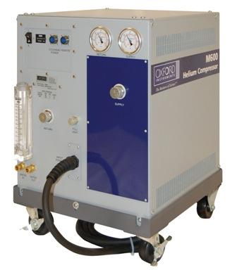
14 cáöìêépjn ModelSMMeÉäáìã`çãéêÉëëçêEï~íÉêJÅççäÉÇãçÇÉäëÜçïåF 9
15 .. Description of Subsystems Along with the five main components, Table - describes the subsystems that serve to monitor the operating condition of the compressor unit and to ensure its safe operation. Table - Subsystem Name Model 600 / Model 00 Helium Compressor Subsystems: Function Phase rotation monitor Internal line break motor protector Overload relay Purpose: Monitors the phase of the input power. Will not allow operation if the phase is incorrect. Located in the center of the Y of the motor windings, disconnects all three phases in case of an overload condition. The internal protector protects against single phasing. Purpose: Monitors system current. Will turn off the compressor if the current level exceeds the preset value. Purpose: Monitors helium temperature upstream of the heat exchanger. Thermal switch (TS) Safety Function: Will turn off the compressor if the helium temperature gets too high. Purpose: Monitors helium temperature downstream of the heat exchanger. Thermal Switch (TS) Bypass valve Oil valve Cooling water flow meter (water-cooled model only) Fuses: Fuses for the coldhead drive circuit Fuses for the main input power Fuses for the control voltage Fuses for the fan motors Fuses for the main contactor coil Internal relief valve External relief valve Safety Function: Will turn off the compressor if the helium temperature gets too high. Purpose and Safety Function: Equalizes pressure within the compressor unit upon power interruption. Purpose and Safety Function: Prevents oil migration when power is off. Purpose: Allows a visual reference as to the current flow rate of the cooling water. Safety Function: Over-current protection Purpose and Safety Function: Opens a shunt between the high and lowpressure helium gas circuits. Sets the proper operating pressure for the system regardless of the load. Safety Function: If the differential pressure exceeds a preset value, this valve opens to allow safe operation. Purpose and Safety Function: Opens the helium gas circuit to atmosphere if the helium gas pressure exceeds 75 PSI. 0
16 .. Operational Flow The work flow of helium gas within the compressor follows these steps:. High-pressure helium gas is delivered from the compressor to the coldhead through the "Supply" helium flex line at 60~80 PSI (M PSI).. The helium gas is then compressed during the compression stroke of the cryopump.. The cryopump then expands the helium gas to expand during its expansion stroke. During this cycle of compression and expansion of the cryopump, the helium gas is forced through regeneration materials to increase the thermodynamic efficiency of the cycle.. With each successive cycle, the regeneration material becomes colder and colder. Eventually, the cryopump temperatures come down to cryogenic range. 5. After expansion, the helium gas returns to the compressor through the "Return" helium flex line at 50~00 PSI (M PSI) to begin the cycle again. The helium flow between the Model 600 / Model 00 compressor s components is illustrated in Figure - and Figure -, for the water-cooled and air-cooled version of the Model 600 / Model 00 compressor, respectively.
17 cáöìêépjo Flowaá~Öê~ãÑçê^áêJ`ççäÉÇjçÇÉäSMMLjçÇÉäQMMeÉäáìã`çãéêÉëëçê
18 FigurePJP cäçïaá~öê~ãñçêt~íéêj`ççäéçjççéäsmmljççéäqmmeéäáìã`çãéêéëëçê
19 PKO pééåáñáå~íáçåë The Model 600 / Model 00 Helium Compressor specifications are listed in Table - and Table -. Table - mçïéêoéèìáêéãéåíëñçêjççéäsmmlmodel ModelQMMeÉäáìã`çãéêÉëëçêë Model Operating AC Voltage [V] (Factory Setting) Frequency [Hz] Phase Max Current Drawn [A] Max Power [kw] Model 600 low voltage (all models) Model 600 high voltage (all models) 00~0 +/-0% (0) 60/ ~80 +/-0% (80) 60/ Model 00 low voltage (all models) Model 00 high voltage (all models) 00~0 +/-0% (0) 60/ ~80 +/-0% (80) 60/ q~ääépjp jççéäsmmljççéäqmmeéäáìã`çãéêéëëçêspecifications Specifications Feature/Component Specification Description Physical Dimensions See Fig lbs for water-cooled model Weight 00 lbs for air-cooled model Static: 0 +/- 5 psig Operating Delta P: Helium Pressure 50 +/- 0 psig (M600) 70 +/- 0 psig (M00) Cold head power connector mates with ASC and CTI drive cables Interface Compressor power cord is equipped with bare ends Helium connections: / inch male Aeroquip couplings 5,000 Hours (per elapsed time meter on the compressor) Adsorber Replacement Schedule or years. Which ever comes first GPM minimum flow rate 65 F~80 F maximum inlet water temperature Recommended chiller capacity: Cooling Water (for water-cooled models) M600.5 ton/per unit M00.0 ton/per unit Water line connector: /8 inch Swagelok Tube Fittings Air-cooled units must maintain a minimum clearance of at Air Cooling (for air-cooled models) least inches at all sides Maximum ambient temperature should not exceed 0 F
20 Figure - Models 600 / Model 00aáãÉåëáçåë 5
21 . Ordering Information Table - contains the ordering information for the Model 600 / Model 00 compressor unit. Table - Model 600 / Model 00 Helium Compressor Ordering Information Compressor Configuration Part Number M600 air-cooled, high voltage, standard drive circuit M600 air-cooled, low voltage, standard drive circuit M600 air-cooled, low voltage, Onboard drive circuit M600 water-cooled, high voltage, standard drive circuit M600 water-cooled, low voltage, standard drive circuit M600 water-cooled, low voltage, Onboard drive circuit M00 air-cooled, high voltage, standard drive circuit M00 air-cooled, low voltage, standard drive circuit M00 air-cooled, low voltage, Onboard drive circuit M00 water-cooled, high voltage, standard drive circuit M00 water-cooled, low voltage, standard drive circuit M00 water-cooled, low voltage, Onboard drive circuit Customers can also order the optional accessories and replacement parts listed in Table -5. 6
22 Table -5 Optional Accessories and Replacement Parts Accessories/Replacement Parts Part Number Adsorber Helium charge line (0ft.*), with bleeder fitting 06 Helium regulator HR-580 Helium lines (0ft.*) 08-0 Helium tee, for connecting two cryopumps T-MMF Three-port manifold, for connecting three cryopumps Splitter box, supplies power to up to three cryopumps 059 Onboard splitter box, supplies power to up to three Onboard cryopumps 066 Maintenance manifold, for helium clean up process on compressors and cryopumps 0 Cryopump drive cable (0ft.*), sends power to the cryopump motor from the compressor 0-0 *Custom length available. 7
23 Installation. Safety Warnings ngs Review the safety warnings in Chapter before beginning any installation activities.. Installation Steps.. Unpacking and Inspection Once the equipment is received, inspect the exterior of the shipping carton for any signs of damage. Report any damage to the shipping company immediately. Remove the straps and packaging materials on the compressor unit, then lift or roll the unit out of the carton carefully. Inspect the exterior of the unit. If any damage is observed, inform the shipping company. Keep the original packaging materials in case the unit needs to be returned to the factory for service or other reasons. Most shipping companies have a certain grace period for reporting damages due to shipping in order to process the insurance information in a timely manner. Therefore it is highly recommended that shipping carton be opened and the unit inspected whether or not it will be put into operation right away. Caution: When transporting or storing the compressor unit, make certain it is not tilted by more than 5 degrees to avoid the unit been tipped over... Mounting the Compressor It is highly recommended that the compressor unit be installed on a level and steady surface. If the unit must be installed in a tilted manner, the maximum tilting angle is 0 degrees. Tilting the unit more than this maximum allowable angle could result in damage and contamination in the system, and may void the warranty on the unit. 8
24 .. Preparing the Compressor for Operation. Check the voltage of the power source before connecting the main power cable to a suitable connector or disconnect box, making sure that the compressor switch is off. If the voltage of the power source is different from the factory default setting (see Chapter, Table -), it may be necessary to change the tap settings on the VAC control transformer located inside the electrical box of the compressor. Follow the steps described in Section..5 to make the change.. For water-cooled Model 600 / Model 00 units, connect the cooling water: a. Typical municipal drinking water is acceptable, however, a closed loop chilled water source is recommended. b. Minimum water flow rate of. -.8 GPM is required to achieve a maximum discharge temperature of 00 F (with 80 F considered ideal). For air-cooled Model 600 / Model 00 units, make sure the front and rear grills have at least inches of clearance from the nearest objects at all sides.. Verify that helium pressure is between 0 +/- 5 psig. If pressure is low, refer to Chapter 7, Section 7..for charging procedures. 5. Start the compressor and run for about 5 minutes to stabilize the compressor oil inventory. 6. The compressor is now ready to be connected to the cryopump or coldhead... Installation... Ambient Conditions and Coolant Connection Ambient Conditions: When the compressor is in operation, the ambient temperature should be between 5 C to 0 C (0 F to 0 F). The compressor unit should be set up in a non-condensing environment. Coolant Connection: Caution: Caution: For water-cooled compressor models, the water used in the unit operation must meet the specifications indicated in Chapter, Section.. Failure to comply with the coolant specifications may result in serious damage to the compressor and may void the warranty on the unit. Identify the inlet and outlet connection ports first before connecting the hoses. The water supply line should be connected to the inlet port on the compressor. An in-line water particulate filter is recommended to prevent heat exchanger fouling. Periodically check the coolant flow rate and temperature to ensure the proper operation of the compressor unit. 9
25 ... Connecting the Helium Flex Lines Caution: Attach or detach the helium flex lines only when the power to the compressor unit is switched off. Never twist the helium flex lines during the installation process. Before connecting the helium flex lines, follow these steps:. Identify the helium Return (low pressure) and Supply (high pressure) ports on the compressor front panel.. Clearly mark the helium flex line that will be used to connect to the corresponding Supply and Return port on the cryopump or coldhead, Note: The helium flex lines are equipped with self-sealing sealing couplings which can be attached and detached without helium escaping. Follow these steps to connect the helium flex lines:. Unscrew the protective caps from the couplings and keep the caps for future use.. Check the connectors for cleanness. When necessary, use lint-free clean cloth or soft brush to clean the connectors.. Check the flat seals on the male couplings and make sure they are properly placed. Replace any missing or defective seals.. Use only the open-wrenches supplied with the installation kit. For a ½" coupling, tighten with a - /6" wrench and stabilize with a " wrench. 5. Tighten down all couplings as far as possible and then back off by one quarter turn to relieve strain. If the flex lines need to be bent to a radii of less than 8" (0 cm), then a 90 degree helium elbow needs to be installed (Chapter, Section. for the part number). 0
26 ... Filling the Compressor with Helium Gas Caution: All safety regulations related to handling pressurized gas cylinders must be observed. Only use helium with % or better purity when performing refill operation. Follow these steps:. Connect a pressure reducer and a helium flex line to a helium supply gas cylinder. Connect the open end of the helium flex line to the helium gas charge/vent valve on the rear panel of the unit, do not tighten the / flare connector on the end of the flex line. Open the valve at the cylinder. Set the pressure of the helium supply cylinder to the value specified in Chapter, Table -. Open the pressure regulator valve slightly so that the helium flex line is purged with helium gas for at least 5 seconds. 5. Tighten the / female Aeroquip fitting on the end of the helium charge line to the gas Fill/Vent Aeroquip fitting of the compressor 6. Open the helium gas Fill/Vent fitting and fill the compressor unit to the desired pressure value. 7. Detach the coupling of the helium charge line from the helium charge/vent valve. 8. Close the helium gas regulator on the supply cylinder. 9. Seal the helium gas Fill/Vent fitting on the compressor unit by properly securing with a protective cap.... Adjusting Helium Gas Pressure Refer to Chapter, Table - for the required pressure specification of the compressor unit. If the pressure falls below that level, the helium gas refill procedure described in Section... to be performed. On the other hand, if the pressure is too high, then the helium gas needs to be released in order to maintain the proper level.
27 ..5 Electrical Connection Caution: Before connecting power to the compressor unit, make sure the factory setting of the operating voltage matches that of the power supply where the unit is being installed. Failure to do so will result in performance degradation of the system. If the voltage of the power source is different from the factory default setting (see Chapter, Table -), it will be necessary to change the tap settings on the VAC control transformer located inside the electrical box of the compressor. Follow the steps described below to make the change:. Unscrew the two side panels of the compressor. Unscrew the top (wrap-around) cover of the unit. Unscrew the electrical box cover. Change taps on the VAC control transformer to the setting that is closest to that of the power source (illustrated in Figure - ) 5. Put back and screw down the electrical box cover 6. Put back and screw down the panels and top cover of the compressor Electrical connections are to be made in accordance with the diagram in Figure - high voltage Model 600 / Model 00 compressor series, and the diagram in Figure - for low voltage models.

28 Figure - ModelSMMLjçÇÉäQMMeÉäáìã`çãéêÉëëçê`çåíêçäsçäí~ÖÉqê~åëÑçêãÉêq~é péííáåöë 0V Setting (Factory setting for low voltage models)
29 5 Operations 5. Before Switching On the System After the compressor unit and its load (cryopump, coldhead, etc.) are installed and connected, check the helium gas pressure as indicated by the pressure gauge mounted on the rear panel of the compressor unit. Refer to Chapter, Section., for the proper static pressure readings for the compressor. If the helium pressure needs to be adjusted, refer to Chapter 7, Section 7.. for procedures to release helium gas in order to reduce the pressure or to fill the compressor with more helium gas to increase the pressure. 5. Normal Operation The load of the compressor can be powered through the power connectors located on the front panel of the compressor. To start operation of the compressor and its load, do the following: Note:. Open the coolant supply (water-cooled compressor model only). Switch on the main power source. Press the ON button to start the compressor. Both the compressor and its load should start simultaneously During initial start-up, the compressor internal relief valve may begin to Chatter. This is a normal occurrence and should subside within a few minutes. During operation, check the coolant flow rate (water-cooled compressor) and the operating pressure frequently. Refer to Chapter, Table - for required coolant flow rate. If it is too slow, make sure any problems associated with water supply or water outlet are resolved. Refer to Chapter, Table - for proper helium pressure level for the compressor unit. If the helium pressure is too low, switch off the compressor unit. It may be necessary to perform a helium "topping-up" maintenance procedure as described in Chapter 7, Section 7... If pressure drop-off happens frequently, there may be a substantial leak in the helium circuit of the compressor. In this case, contact Oxford Instruments Austin, Inc. customer service immediately. To shut down the compressor unit, press the OFF button on the front panel. After that, allow coolant to continue to circulate for at least 0 more minutes before shutting off flow.
30 5.. Cycle Times There is no set answer to how often the cryogenic compressor can be started and stopped in an hour. Oxford Instruments Austin, Inc. recommends a maximum of twelve cycles per hour. One critical consideration is a minimum run time required to return oil to the compressor after start up. To assure proper oil return, one minute is the minimum run time for all cryogenic compressors. A second consideration is a four minute minimum off cycle time once the compressor cycles off. 5. Electronics Interface Connections 5.. J Remote Interface The Model 600 / Model 00 Compressor provide a D-sub 5 connector for remote interface control and status collection. Table 5-5 J Remote Connector (5-pin D-sub) D Pin Number Assignment Pin Number No Connect No Connect No Connect 5 No Connect Assignment Reset 6 Pressure Alarm Cold Head ON/OFF 7 Phase Error 5 No Connect 8 Temp Alarm 6 Compressor ON/OFF 9 Run Status (Compressor ON ) 7 No Connect 0 No Connect 8 No Connect No Connect 9 No Connect No Connect 0 No Connect No Connect No Connect Ground No Connect 5 +V Output No Connect 5
31 5.. D-sub User Controls The Model 600 / Model 00 Compressor input control signals (pins,, 6) require a user slide switch or opto-coupler as shown in the figure below. Figure 5-5 User Control C Signal Interface Example: To start the compressor connect pin 6 to pin. To start the coldhead, connect pin to pin. 6
32 5.. D-sub User Status The Model 600 / Model 00 Compressor output status signals (pins 6-9) are designed to drive a user side opto-coupler as shown in the figure below. Figure 5-5 User Status Signal Interface Example: Use the output voltage from pin 9 & 5 to monitor the run status of the compressor, this output can be used to drive a LED or used as an input to a PLC. 7
33 5.. Compressor Front Panel User Interface On start-up, the Model 600 / Model 00 Compressor front panel LCD will display the title screen and revision information. Once initialization is complete, the main screen is displayed. Note: If the phases are not connected properly, a Phase Error will be displayed. The compressor cannot be started until the unit is powered down and the phase error is corrected. The compressor provides buttons and a -line display for easy operation: Off On Menu Pressing the Off button from any screen results in powering the compressor off. The unit can only be turned on if all operational checks are passed. If a system error occurs, pressing the Menu button displays the status of each system check. If all operational checks are successful, pressing the Menu button displays the operating hours on the compressor. The On button powers the compressor if all system checks are successful. If a system check is in the failed state, the On button is ignored Compressor Operational Checks Table 5-5 Operational Checks System Interlock Fault Helium Pressure Alarm Pressure alarm contact is not OPEN. Verify pressure contact. Helium Temperature re Alarm Temperature alarm contact is not OPEN. Verify temperature contact. Contactor Alarm Contractor overload tripped Compressor System Shut Down Manual shut-down Push the OFF button Automatic shut-down The following system indication will cause the compressor to automatically shut down:. Low Helium pressure. High Helium temperature. Contactor Overload 8
34 If an automatic shut down occurs, refer to Chapter 5, Table 5- to identify and remove the fault. Once the fault has been corrected, the user can restart the system by pressing the ON button Compressor Interfaces Serial Port Interface The Model 600 / Model 00 Compressor provide a DB9 Male connector for serial port communications. A straight through serial cable, as shown in the table below, is necessary for interfacing to the serial port. Only pins,, and 5 are required. Table 5-5 Serial Port Interface (J RS) Pin Assignment DB9 Female (to Compressor) DB9 (to Controller) (TxD) (RxD) (RxD) (TxD) (Gnd) (Gnd)
35 5..8 Serial Port Cable Table 5-5 Serial Port Settings Baud Rate 800 Data Bits 8 Parity NONE Start Bits Stop Bits NONE 5..9 Communications No handshaking PC is always the host. Commands and data requests from host. Message Format: o Byte : STX (0h control-b) o Bytes.. Command or data request o Bytes 5..X Command or requested data o Byte X+ (Carriage Return 0Dh) All bytes are ASCII type (0h..7Fh) Maximum value for X is 6. Individual data values are separated by a forward slash Used letters are ASCII capitals. Used numbers are ASCII decimals. Incorrect formats are ignored Serial Port Commands The following serial port commands are provided: Table Serial Port Commands Command Message Command No. of Bytes Description Send: STX SYS CR ++ Turn System On Receive: STX SYS CR ++ System Error 0
36 Table Data Message Command No. of Bytes Description Send: STX DAT CR ++ Data request Receive: STX DAT SW Version Reserved Hours Counter Reserved On Timer(seconds) Status: 0 Off CR On System Error Compressor Status: 0 Off On Reserved Number of active errors active error 0 error inactive Number of errors logged ( 8) End of message Table Command/Data Send Compressor Description STX SYS x CR STX SYS y CR X Y 0 Off X Y On Y System Error STX SC x y CR STX SC x y CR X Cold Head Y On Y 0 Off STX DAT CR As described in previous table Data Requested STX ERR CR STX ERR xx hhhhh / xx hhhhh / xx hhhhh CR xx error code (Will display last 8 error codes) hhhhh hours counter
37 Example: STX SYS CR Turns the compressor on, The system will respond with SYS STX SYS0 Turns the compressor off SXT CR Coldhead On the compressor will return SC Note the compressor must be running to turn the Coldhead on. Table Error Codes Error Code Display Description System Error Error has occurred - Reserved Contactor Error Compressor overload relay has tripped off. 5 Phase/Fuse Error Line voltage out of Phase. Fuses blown 6 Pressure Alarm Low pressure switch tripped 7 Temperature Fail Thermal Switch has tripped Coolant Supply Failure Lack of cooling 8-6 Reserved
38 6 Troubleshooting 6. Troubleshooting Activities Table 6- describes some problems that users might encounter while operating the Model 600 / Model 00 Helium Compressor and provides solutions to those problems. Additional troubleshooting information can be found in Chapter 5, Table 5-8. If a compressor problem still persists after performing the corrective actions described in this section, please contact Oxford Instruments Austin, Inc. Technical Support for further assistance. Refer to Chapter, Section. for contact information.
39 Table 6-6 Troubleshooting Procedures Problem The compressor On/Off switch (SW) is in the On position but will not start. Compressor stops after several minutes of operation and remains off. Possible Cause. No power is coming from the power source.. Incorrect or disconnected wiring within the compressor. Thermal protection switch (TS and/or TS) is open.. High current has tripped the current overload relay. 5. The LCD display goes out when the start button is pressed.. High temperature of the compressor caused by insufficient cooling water (for water-cooled model), resulting in the opening of thermal protection switches (TS and/or TS). For aircooled model, the ambient temperature is too high.. Insufficient helium static pressure.. High temperature helium gas tripped the thermal protection switch (TS).. Low power source voltage. 5. Mechanical seizure. Corrective Action. Check service fuses, circuit breakers, and wiring associated with the power source. Repair as needed.. Check the compressor wiring against the wiring schematic. See Chapter, Figure - or Figure -.. Confirm that switch TS and/or TS is closed. The compressor will display over temperature on the status menu.. Reset the current overload relay. 5. Check for the proper transformer wiring figure.. Confirm that sufficient cooling water (for watercooled model) is flowing to the compressor. For aircooled model, provide additional cooling to the surrounding environment.. Add helium, using the procedures described in Chapter 7, Section Check for proper cooling of the compressor unit.. Confirm that power source voltage is correct. 5. Contact Oxford Instruments Austin, Inc. for assistance.
40 T j~áåíéå~ååé 7. Maintenance Personnel Requirements Only trained and qualified personnel should perform the maintenance procedures described in this chapter. All other maintenance work must be performed by Oxford Instruments Austin, Inc. personnel in the factory. Please contact Oxford Instruments Austin, Inc. to make arrangement for such work. See contact information in Chapter, Section.. 7. Removing the Compressor from Service: Removal, Transport, and Storage It is recommended that the Model 600 / Model 00 compressor be removed from service when carrying out the maintenance duties described in Chapter 7, Section 7.. To remove the compressor unit from service, do the following:. Turn off the compressor unit by pressing the OFF button. Switch off the main power supply to the compressor. Separate the compressor unit from the main power source. Allow coolant to continue circulate for at least 0 more minutes (for water-cooled model) 5. Allow the compressor load (cryopump, coldhead, etc.) to warm up before detaching helium flex lines Caution: Loosening or detaching helium flex lines with the compressor load at low temperature without proper warming-up can result in loss of helium and/or pressure rise in the compressor unit beyond its designed maximum pressure level. When transporting the compressor unit, follow these guidelines: Make sure the appropriate protective caps are properly secured before shipping. Always store the compressor unit in a dry place. Refer to Chapter, Table - for proper storage environment. If a freezing temperature environment is anticipated whether during shipping or under storage, make certain the coolant in the compressor circuit is properly drained. Caution: The compressor unit should never be tilted more than 5 degrees either during shipping ping or in storage. 5
41 7. Scheduled Preventative Maintenance Activity The only scheduled maintenance required on the Model 600 / Model 00 compressor is the replacement of compressor adsorber after every 5,000 hours of operation as indicated on the compressor elapsed time meter or years, which ever comes first The adsorber is used to keep the oil vapor out of the helium gas in the flow circuit of compressor unit and its load. After about 5,000 hours of operation or years, the effectiveness of the adsorber will decrease. It will then need to be replaced. Otherwise the oil particles could accumulate on the cold surface of the compressor load, reducing the cooling performance of the overall system. In severe cases of such oil contamination, the load (cryopump, coldhead, etc.) could cease to function completely. To remove and replace the compressor adsorber, follow the steps described in Chapter 7, Section 7.. and Chapter 7, Section 7... Caution: Use only Oxford Instruments Austin, Inc. supplied adsorber r for replacement. Refer to Chapter, Section. for the part number. 7.. Remove the Compressor Adsorber To remove the compressor adsorber:. Turn off the compressor and separate it from the main power supply.. Allow sufficient time for the load of the compressor (cryopump or coldhead) to warm up before detaching the helium flex lines from the compressor. Refer to Chapter, Section. for proper procedures to detach helium flex lines. Caution: Detaching helium flex lines with the compressor load at low temperature t could result in loss of helium gas. It may also cause the pressure rise in the system beyond the permissible level therefore creating a safety hazard.. Use the two wrenches supplied with the (optional) Installation Kit to avoid loosening the body of the coupling from its adapter. Hold one wrench tight on the coupling half attached to the rear side of the compressor. Use the other wrench to loosen the coupling to the helium supply line.. Unscrew the two-self sealing coupling halves quickly to minimize minor gas leakage. Figure 7-9 contains an illustration of the self-sealing couplings. 5. Detach the helium flex line from the helium supply connection located on the adsorber panel on the front panel. See Figure Unscrew and remove the nut and washer of the helium supply connector. 7. Unscrew the six screws holding the adsorber panel on the front panel, as illustrated in Figure Once the adsorber panel is removed, the adsorber should be in full view. Remove the two screws that hold the adsorber to the bottom of the compressor chassis, as illustrated in Figure 7- and Figure 7-. 6
42 9. There is a short section of helium flex line that connects the adsorber with the oil-mist separator of the compressor. Unscrew the connection. See Figure Slightly pull the adsorber assembly towards the front. Then tilt the assembly to remove it from the chassis, as illustrated in Figure Remove the adsorber and save all nuts, bolts, and washers for installing the replacement adsorber (Figure 7-7 and Figure 7-8).. The removed adsorber can be returned to Oxford Instruments Austin, Inc. for credit. Chapter, Section. provides the contact information. 7.. Install Replacement Adsorber To install the replacement adsorber:. Remove the dust caps from the self-sealing coupling halves at each end of the replacement adsorber.. Check the self-sealing connector flat rubber gasket to make sure that it is clean and properly positioned.. Place the adsorber back in the compressor using the nuts, bolts, and washers set aside during the removal process described in Step 5 of Chapter 7, Section Install the two-self sealing coupling halves quickly to minimize minor gas leakage. 5. Use the two wrenches supplied with the (optional) Installation Kit, holding one wrench tight on the coupling half attached to the rear side of the compressor. Use the other wrench to tighten the coupling to the helium supply line. 6. Make the final turns by hand and then use the wrenches until the fittings bottom out. 7. Replace the adsorber panel and the flex lines. 8. Make sure the supply pressure gauge reads 0 +/- 5 psig. If the pressure is either too high or too low, follow the instructions in Chapter 7, Section 7.. to fill the helium gas to the proper pressure level. 9. Add 5,000 to the reading of the elapsed time meter and write this number on the decal provided with the replacement adsorber. This decal can be affixed to the foot of the compressor. 0. Restart the compressor. 7


43 Figure 7. Step Figure 7. Step 8 The Business of Science
 9 The Business of Science")
44 Figure Figure 7. Step (a) Figure 7. Step (b) 9 The Business of Science

45 Figure 77-5 Step Figure 77-6 Step 5 0 The Business of Science
 Figure 77-8")

46 Figure 77-7 Step 6 (a) Figure 77-8 Step 6 (b) The Business of Science
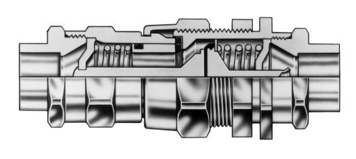
47 Figure jççéäsmmljççéäqmmpéäñjpé~äáåö`çìéäáåöáå`äçëéçmçëáíáçå
48 7. Unscheduled Corrective Maintenance The following corrective maintenance activities may be necessary should the helium gas circuit of Model 600 / Model 00 compressor becomes contaminated. 7.. Adding Helium Gas If a compressor unit needs to have helium gas added more than once every several months, check for leaks caused by improperly connected self-sealing connections or incorrectly sealed charge valve. If the compressor unit is connected to its load (cryopump, coldhead, etc.), check for leaks in the load also. Use only % pure helium gas. To add helium gas:. Remove the Aeroquip cap of the Helium Fill/Vent fitting on the front of the compressor.. A user-supplied helium charge line terminating in a / inch female Aeroquip fitting and a pressure regulator rated at 00 psig delivery pressure is required.. Set the helium pressure regulator to 0 to 5 psig. Allow helium gas to flow through the charging female Aeroquip fitting for 0 seconds to purge the charge line of air. Then tighten the flare nut at the end of the charge line.. Loosely attaching a charge line from the helium pressure regulator on the helium pressure bottle to the / inch male Aeroquip fitting installed on the helium Fill/Vent fitting. a. If the compressor has been running under normal operating conditions and is up to operating temperature, set the helium pressure regulator to 5 psig and slowly open the helium charge valve on the regulator. When the helium supply pressure gauge rises to 50 to 60 psig, tightly close the charger valve. b. If the compressor is not running, set the helium pressure regulator to 50 psig and slowly open the helium charge valve. When the helium supply pressure gauge rises to 0 +/-5 psig, tightly close the charge valve. 5. Insure that the helium charge valve on the regulator is tightly closed. Then shut off the helium pressure regulator on the helium bottle. Remove the charge line from the male Aeroquip fitting and reinstall the cap.
Model 600/Model 400. Cryogenic Helium Compressor. Users Manual
 Model 600/Model 400 Cryogenic Helium Compressor Users Manual Oxford Instruments Austin, Inc. 1340 Airport Commerce Dr. Bldg. 1 Suite 175 Austin, TX 78741 USA Sales: 800-611-8871 Support: 800-404-1055 cryo-sales@oxinst.com
Oxford Instruments Austin, Inc.
 User's User s Manual Issue 01 / March 2013 / OIAI Cryo-Plex 10 Oxford Instruments Austin, Inc. Issue 01 / March 2013 / Original Instructions Oxford Instruments Austin, Inc. is a wholly-owned subsidiary
Oxford Instruments Austin, Inc.
 User User Manual Manual Issue 01 / November 2013 / Oxford Instruments Austin, Inc. Issue 01 / November 2013 / Original Instructions Original Instructions Issue 01 / November 2013 / Oxford Instruments Austin,
Trillium US Inc. Cryo-Plex 10 Cryogenic High Vacuum Pump User s Manual Rev A / November 2015
 97-00032-000 Trillium US Inc. Cryo-Plex 10 Cryogenic High Vacuum Pump User s Manual Rev A / November 2015 For information about Trillium US Inc., visit the Trillium US Inc. Web site at: http://www.trilliumus.com
Trillium US Inc. Model 250 / Model 350 Cryogenic Helium Compressor User s Manual Rev E / May 2017
 97-00056-000 Trillium US Inc. Model 250 / Model 350 Cryogenic Helium Compressor User s Manual Rev E / May 2017 For information about Trillium US Inc., visit the Trillium US Inc. Web site at: http://www.trilliumus.com
9600 Compressor Installation, Operation, and Maintenance Instructions Rev. G (1/99)
") 9600 Compressor Installation, Operation, and Maintenance Instructions 8040444 Rev. G (1/99) TECHNOLOGY CORPORATION Mansfield Corporate Center, Nine Hampshire Street, Mansfield, Massachusetts 02048-9171
9600 Compressor Installation, Operation, and Maintenance Instructions 8040444 Rev. G (1/99) TECHNOLOGY CORPORATION Mansfield Corporate Center, Nine Hampshire Street, Mansfield, Massachusetts 02048-9171
TECHNICAL DATA MAINTENANCE AIR COMPRESSOR MODEL G-1
 Dry 131h 1. DESCRIPTION The Viking Model G-1 Maintenance Air Compressor is an electric motor-driven, aircooled, single-stage, oil-less compressor. The unit is equipped with a check valve and provides a
RDK-408D2 Cold Head. Technical Manual. SHI-APD Cryogenics Inc Vultee Street Allentown, PA U.S.A. Revision A: September 2005
 RDK-408D2 Cold Head Technical Manual SHI-APD Cryogenics Inc. 1833 Vultee Street Allentown, PA 18103-4783 U.S.A. Revision A: September 2005 (Reference SHI Manual: December 18, 2003 266404A CD32ZZ-160A)
Budget Range Operators Handbook
 Budget Range Operators Handbook BAMBI AIR COMPRESSORS LTD 152 Thimble Mill Lane Heartlands Birmingham B7 5HT United Kingdom Tel: 0121 322 2299 Fax: 0121 322 2297 Email: sales@bambi-air.co.uk www.bambi-air.co.uk
3 GALLON, OILLESS PANCAKE COMPRESSOR INSTRUCTIONS. Item #31289
 3 GALLON, OILLESS PANCAKE COMPRESSOR INSTRUCTIONS Item #31289 The EASTWOOD 3 GALLON, OILLESS PANCAKE COMPRESSOR, with an Integral Air Regulator, efficiently supplies all compressed air requirements for
MODEL NUMBER: PSI AIR SOURCE KIT 200 PSI Compressor on 2.0 Gallon 200 PSI Air Tank
 IMPORTANT SAFETY INSTRUCTIONS CAUTION - To reduce risk of electrical shock or Electrocution: MODEL NUMBER: 20008 200 PSI AIR SOURCE KIT 200 PSI Compressor on 2.0 Gallon 200 PSI Air Tank IMPORTANT: It is
BIMA cryogenics (Dick Plambeck, 18jan2007)
") BIMA cryogenics (Dick Plambeck, 18jan2007) Normal operation. Monitor from the antennas > 6-meter > receivers multiple> cryo rtd page. Troubleshooting. sensor what is it? normal range stage1 outer dewar
BIMA cryogenics (Dick Plambeck, 18jan2007) Normal operation. Monitor from the antennas > 6-meter > receivers multiple> cryo rtd page. Troubleshooting. sensor what is it? normal range stage1 outer dewar
9600 (High Voltage) Compressor Installation, Operation, and Maintenance Instructions
 Compressor Installation, Operation, and Maintenance Instructions") 9600 (High Voltage) Compressor Installation, Operation, and Maintenance Instructions 2007 Helix Technology Corporation Pub. No. 8040437, Rev. 04, 06/2/2007 ECO No.8068 Printed in USA HELIX TECHNOLOGY CORPORATION
9600 (High Voltage) Compressor Installation, Operation, and Maintenance Instructions 2007 Helix Technology Corporation Pub. No. 8040437, Rev. 04, 06/2/2007 ECO No.8068 Printed in USA HELIX TECHNOLOGY CORPORATION
NGP-250/500 Nitrogen Generator Quick Start Guide
 NGP-250/500 Nitrogen Generator Quick Start Guide Version: A July 2013 Potter Electric Signal Company, LLC 5757 Phantom Dr., Suite 125 P. O. Box 42037 Hazelwood, MO 63042 Phone: (314) 595-6900 Document
MODEL NUMBER: M20005 AIR SOURCE KIT. 30% Duty Compressor on. 2.0 Gallon Air Tank SAVE THIS MANUAL FOR FUTURE REFERENCE
 MODEL NUMBER: M20005 AIR SOURCE KIT 30% Duty Compressor on 2.0 Gallon Air Tank SAVE THIS MANUAL FOR FUTURE REFERENCE USER MANUAL IMPORTANT SAFETY INSTRUCTIONS CAUTION - To reduce risk of electrical shock
Model PSI Compressor with 3-Gallon Air Tank 12VDC
 Model 6350 150 PSI Compressor with 3-Gallon Air Tank 12VDC IMPORTANT: It is essential that you and any other operator of this product read and understandd the contents of this manual before installing
200 PSI HIGH-FLOW AIR SOURCE KIT
 200 PSI HIGH-FLOW AIR SOURCE KIT 50% Duty Compressor on 2.0 Gallon Air Tank PART NO. 20008 IMPORTANT: It is essential that you and any other operator of this product read and understand the contents of
444C DUAL PERFORMANCE VALUE PACK
 (Chrome) PART NO. 44432 IMPORTANT: It is essential that you and any other operator of this product read and understand the contents of this manual before installing and using this product. SAVE THIS MANUAL
420C AIR COMPRESSOR KIT PART NO C AIR COMPRESSOR KIT PART NO
 420C AIR COMPRESSOR KIT PART NO. 42042 460C AIR COMPRESSOR KIT PART NO. 46043 420C 460C IMPORTANT: It is essential that you and any other operator of this product read and understand the contents of this
SPECIFICATIONS Type: Twin stack, single phase Tank: 4 gallon Air Output: PSI; PSI Max PSI: 125 PSI HP: 1.
 2 GALLON TWIN STACK AIR COMPRESSOR Model: 9526 DO NOT RETURN TO STORE. Please CALL 800-348-5004 for parts and service. CALIFORNIA PROPOSITION 65 WARNING: You can create dust when you cut, sand, drill or
200 PSI FAST-FILL AIR SOURCE KIT
 200 PSI FAST-FILL AIR SOURCE KIT 55% Duty Compressor on 2.0 Gallon Air Tank PART NO. 20007 IMPORTANT: It is essential that you and any other operator of this product read and understand the contents of
Pressure Dump Valve Service Kit for Series 3000 Units
 Instruction Sheet Pressure Dump Valve Service Kit for Series 000 Units. Overview The Nordson pressure dump valve is used to relieve hydraulic pressure instantly in Series 00, 400, 500, and 700 applicator
200 PSI COMPRESSORS - MODEL NUMBERS
 200 PSI COMPRESSORS - MODEL NUMBERS 380C AIR COMPRESSOR KIT PART NO. 38033 480C AIR COMPRESSOR KIT PART NO. 48043 380C 480C IMPORTANT: It is essential that you and any other operator of this product read
100C Air Compressor Kit
 10010 100C Air Compressor (standard mounting bracket, CE Spec) 10014 100C Air Compressor (no leader hose or check valve, CE Spec) 10016 100C Air Compressor (with Omega Bracket, CE Spec) IMPORTANT: It is
AMP Oil Free Manual AMP 50-8-TC AMP 50-6-D AMP General User and Maintenance Instructions
 AMP Oil Free Manual AMP 50-8-TC AMP 50-6-D AMP 50-24 General User and Maintenance Instructions Silentaire Technology 8614 Veterans Memorial Dr. Houston, TX 77088 800-972-7668 Fax 832-327-0669 www.silentaire.com
AIR COMPRESSOR. Failure to follow all instructions as listed below may result in electrical shock, fire, and/or serious personal injury.
 2 GALLON AIR COMPRESSOR Model: 7517 DO NOT RETURN TO STORE. Please CALL 800-348-5004 for parts and service. CALIFORNIA PROPOSITION 65 WARNING: You can create dust when you cut, sand, drill or grind materials
SPECIFICATIONS ATTENTION
 VPS 504 S06 Installation Manual - P/N 80122 - Ed. 01/09 VPS 504 S06 and S05 Valve Proving System Installation Instructions VPS 1 6 Gases Natural gas, air and other inert gases. NOT suitable for butane
400C & 450C DUAL PERFORMANCE VALUE PACKS
 (Chrome) PART NO. 40013 (Silver) PART NO. 45012 (Chrome) PART NO. 45013 IMPORTANT: It is essential that you and any other operator of this product read and understand the contents of this manual before
400H HARDMOUNT AIR COMPRESSOR KIT PART NO H HARDMOUNT AIR COMPRESSOR KIT PART NO
 400H HARDMOUNT AIR COMPRESSOR KIT PART NO. 40042 450H HARDMOUNT AIR COMPRESSOR KIT PART NO. 45042 400H 450H IMPORTANT: It is essential that you and any other operator of this product read and understand
IMPORTANT SAFETY INSTRUCTIONS
 IMPORTANT SAFETY INSTRUCTIONS CAUTION - To reduce risk of electrical shock: - Do not disassemble. Do not attempt repairs or modifications. Refer to qualified service agencies for all service and repairs.
INSTALLATION GUIDE Gas Rangetops
 INSTALLATION GUIDE Gas Rangetops Contents Wolf Gas Rangetops........................... 3 Safety Instructions............................ 4 Gas Rangetop Specifications.................... 5 Gas Rangetop
RPS900W Redundant Power Supply. Installation Guide.
 RPS900W Redundant Power Supply Installation Guide www.edge-core.com Installation Guide RPS900W Redundant Power Supply Single DC Output Port with Dual Output Voltages RPS900W E10013-CS-R01 1500000081A
Workhorse-15 Oxygen Generator
 11436 Sorrento Valley Road, San Diego CA 92121 USA 858-558-0202 Fax 858-558-1915 Workhorse-15 Oxygen Generator Model No. 5719, 5727, 5735 for Domestic and International Units Part number 1432 Revision
Pressure Dump Valve Service Kit for Series 2300 Units
 Instruction Sheet Pressure Dump Valve Service Kit for Series 00 Units. Overview The Nordson pressure dump valve is used to relieve hydraulic pressure instantly in Series 00 applicator tanks when the unit
2 GALLON TWIN STACK AIR COMPRESSOR W/ HOSE REEL
 2 GALLON TWIN STACK AIR COMPRESSOR W/ HOSE REEL Model: 52024 CALIFORNIA PROPOSITION 65 WARNING: You can create dust when you cut, sand, drill or grind materials such as wood, paint, metal, concrete, cement,
AIR COMPRESSOR OPERATING INSTRUCTION AND PARTS LIST
 AIR COMPRESSOR OPERATING INSTRUCTION AND PARTS LIST OIL-LESS TYPE IMPORTANT: PLEASE READ CAREFULLY BEFORE STARTING OPERATIONS. THE CONTENTS ARE FOR GENERAL INFORMATION OF ALL THE SIMILAR MODELS. Record
R E D I C O N T R O L S
 R E D I C O N T R O L S Operation & Maintenance Manual Portable Service Purger for Low Pressure Chillers Model: PSP-LP-1B For Refrigerants R-11, R-113, R-114 & R-123 & Other Similar Refrigerants File Literature
PROPORTIONING VALVE. Model 150 INSTRUCTION MANUAL. March 2017 IMS Company Stafford Road
 PROPORTIONING VALVE Model 150 INSTRUCTION MANUAL March 2017 IMS Company 10373 Stafford Road Telephone: (440) 543-1615 Fax: (440) 543-1069 Email: sales@imscompany.com 1 Introduction IMS Company reserves
97C COMPRESSOR KIT 12V PART NO C COMPRESSOR KIT 24V PART NO C COMPRESSOR KIT PART NO
 97C COMPRESSOR KIT 12V PART NO. 00097 97C COMPRESSOR KIT 24V PART NO. 02497 98C COMPRESSOR KIT PART NO. 00098 97C 98C IMPORTANT: It is essential that you and any other operator of this product read and
NB/NBR NITROGEN BOOSTER FOR AVIATION SERVICE
 NB/NBR NITROGEN BOOSTER FOR AVIATION SERVICE INSTALLATION, OPERATION & MAINTENANCE MANUAL INTERFACE DEVICES, INC. 230 Depot Road, Milford, CT 06460 Ph: (203) 878-4648, Fx: (203) 882-0885, E-mail: info@interfacedevices.com
ULTRA-LIGHT DUTY ONBOARD AIR SYSTEM
 ULTRA-LIGHT DUTY ONBOARD AIR SYSTEM PART NO. 10000 IMPORTANT: It is essential that you and any other operator of this product read and understand the contents of this manual before installing and using
accidents which arise due to non-observance of these instructions and the safety information herein.
 3 GALLON PANCAKE COMPRESSOR Model: 50959 CALIFORNIA PROPOSITION 65 WARNING: You can create dust when you cut, sand, drill or grind materials such as wood, paint, metal, concrete, cement, or other masonry.
Booster Pump PB4-60 Replacement Kits
 Booster Pump PB4-60 Replacement Kits FOR YOUR SAFETY - This product must be installed and serviced by a contractor who is licensed and qualified in pool equipment by the jurisdiction in which the product
TANK MANAGER FOR TWO TANKS OPERATING MANUAL. 10/31/11 C-More T6C L color touch panel
 TANK MANAGER FOR TWO TANKS OPERATING MANUAL 10/31/11 C-More T6C L color touch panel 1 TABLE OF CONTENTS GENERAL...3 INSTALLATION...4 STONE TEST PROCEDURE...7 OPERATIONAL SUMMARY...7 AUTO CARBONATION...10
Operation Manual - PN A MENSOR MODEL 73 SHOP AIR BOOSTER
 Operation Manual - PN 0017946001 A MENSOR MODEL 73 SHOP AIR BOOSTER Mensor Model 73 Shop Air Booster System (750 psi Version) April 23, 2012 Trademarks / Copyright Mensor is a registered trademark of Mensor
120 PSI FAST-FILL AIR SOURCE KIT 25% Duty Compressor on 1.5 Gallon Air Tank
 120 PSI FAST-FILL AIR SOURCE KIT 25% Duty Compressor on 1.5 Gallon Air Tank PART NO. 20003 IMPORTANT: It is essential that you and any other operator of this product read and understand the contents of
250C-IG COMPRESSOR KIT 12V PART NO C-IG COMPRESSOR KIT 24V PART NO
 250C-IG COMPRESSOR KIT 12V PART NO. 25050 250C-IG COMPRESSOR KIT 24V PART NO. 25058 IMPORTANT: It is essential that you and any other operator of this product read and understand the contents of this manual
Inert Air (N2) Systems Manual
 Systems Manual") INSTRUCTION MANUAL Inert Air (N2) Systems Manual N2-MANUAL 2.10 READ AND UNDERSTAND THIS MANUAL PRIOR TO OPERATING OR SERVICING THIS PRODUCT. GENERAL INFORMATION Positive pressure nitrogen gas pressurizing
INSTRUCTION MANUAL Inert Air (N2) Systems Manual N2-MANUAL 2.10 READ AND UNDERSTAND THIS MANUAL PRIOR TO OPERATING OR SERVICING THIS PRODUCT. GENERAL INFORMATION Positive pressure nitrogen gas pressurizing
250C-IG COMPRESSOR KIT 12V PART NO C-IG COMPRESSOR KIT 24V PART NO
 250C-IG COMPRESSOR KIT 12V PART NO. 25050 250C-IG COMPRESSOR KIT 24V PART NO. 25058 IMPORTANT: It is essential that you and any other operator of this product read and understand the contents of this manual
42045 Heavy Duty ADA Base Model Kit: 85/105 PSI (ADA Compressor Only) Heavy Duty ADA Base Model Kit: 110/145 PSI (ADA Compressor Only)
 Heavy Duty ADA Base Model Kit: 110/145 PSI (ADA Compressor Only)") 42045 Heavy Duty ADA Base Model Kit: 85/105 PSI (ADA Compressor Only) 42047 Heavy Duty ADA Base Model Kit: 110/145 PSI (ADA Compressor Only) 45052 Constant Duty ADA Base Model Kit: 85/105 PSI (ADA Compressor
42045 Heavy Duty ADA Base Model Kit: 85/105 PSI (ADA Compressor Only) 42047 Heavy Duty ADA Base Model Kit: 110/145 PSI (ADA Compressor Only) 45052 Constant Duty ADA Base Model Kit: 85/105 PSI (ADA Compressor
FOR INSTALLING CO 2 BLENDER KIT (P/N IN BEER SYSTEM
 IMI CORNELIUS INC One Cornelius Place Anoka, MN 55303-623 Telephone (800) 238-3600 Facsimile (612) 22-326 INSTALLATION INSTRUCTIONS FOR INSTALLING CO 2 BLENDER KIT (P/N 111612000 IN BEER SYSTEM SECONDARY
Gas Lines. Technical Manual. Sumitomo (SHI) Cryogenics of America, Inc Vultee Street Allentown, PA U.S.A.
 Cryogenics of America, Inc Vultee Street Allentown, PA U.S.A.") Gas Lines Technical Manual Sumitomo (SHI) Cryogenics of America, Inc. 1833 Vultee Street Allentown, PA 18103-4783 U.S.A. Revision F: April 2008 261320A TABLE OF CONTENTS Page DESCRIPTION...1 SPECIFICATIONS...2
Gas Lines Technical Manual Sumitomo (SHI) Cryogenics of America, Inc. 1833 Vultee Street Allentown, PA 18103-4783 U.S.A. Revision F: April 2008 261320A TABLE OF CONTENTS Page DESCRIPTION...1 SPECIFICATIONS...2
Rejuvenation Instructions
 Rejuvenation Instructions #401 Air Systems UPR This NRI covers the following: Understanding the applications and operation of flow meters. Understand the application and operation of test pressure gauges.
SILENTAIRE TECHNOLOGY
 SILENTAIRE TECHNOLOGY General User and Maintenance Instructions Thank you and congratulations on the purchase of your PANTHER, the leader in the industry of portable air compressors. The PANTHER is built
24L OIL FREE AIR COMPRESSOR MODEL NO: TIGER 7/250 PART NO: OPERATION & MAINTENANCE INSTRUCTIONS LS10/13
 24L OIL FREE AIR COMPRESSOR MODEL NO: TIGER 7/250 PART NO: 2244030 OPERATION & MAINTENANCE INSTRUCTIONS LS10/13 INTRODUCTION Thank you for purchasing this product. Before attempting to use this product,
OPERATION MANUAL NTF-15
 OPERATION MANUAL NTF-15 Nitrogen Tire Filling Valve Stem Caps (Qty=200) Order P/N 436075 RTI Technologies, Inc 10 Innovation Drive York, PA 17402 800-468-2321 www.rtitech.com 035-81235-00 (Rev B) TABLE
TECHNICAL DATA. Q = C v P S
 Preaction 346a 1. Description The 6 Model G-6000P Electric Release Preaction System Riser Assembly can be used as a Single Interlock Preaction System with Electric Release, or as a Double Interlock Preaction
VERTICAL AIR COMPRESSORS
 VERTICAL AIR COMPRESSORS MODEL NO: VE15C150, VE18C150, VE25C150 PART NO: 2226010, 2226020, 2226025 OPERATION & MAINTENANCE INSTRUCTIONS LS0715 INTRODUCTION Thank you for purchasing this CLARKE Vertical
OPERATION MANUAL. SRDK Series CRYOCOOLER. For Service Personnel Only. Sumitomo Heavy Industries, Ltd. Cryogenics Division
 MANUAL NUMBER: CD32ZZ-063I DATE: December 18 / 2003 OPERATION MANUAL SRDK Series CRYOCOOLER For Service Personnel Only Cryogenics Division 2-1-1 Yato-cho, Nishitokyo-City, Tokyo 188-8585, Japan TEL: +81-424-68-4240
TECHNICAL DATA. Q = C v P S
 January 6, 2012 Preaction 347a 1. Description Viking supervised Double-Interlocked Electric/Pneumatic Release Preaction Systems utilize the Viking G-6000P Valve. The small profile, lightweight, pilot operated
RecoverXLT2-AP Oil-Less Universal Refrigerant Recovery System Operation and Maintenance Manual
 RecoverXLT2-AP Oil-Less Universal Refrigerant Recovery System Operation and Maintenance Manual (English) Table of Contents General Safety Instructions 2-3 RecoverXLT2-AP Operation Guide Direct Liquid Recovery
Cryogenic Refrigerator. INSTALLATION, OPERATION and ROUTINE MAINTENANCE MANUAL
 Cryogenic Refrigerator INSTALLATION, OPERATION and ROUTINE MAINTENANCE MANUAL The information contained in this document is believed to be accurate and reliable as of the time of its publication. However,
INSTRUCTION MANUAL FOR MODEL 7360V VERTICAL CURING CHAMBER Revision E May
 INSTRUCTION MANUAL FOR MODEL 7360V VERTICAL CURING CHAMBER Revision E May 2015 98-0520 S/N 2001 N. Indianwood Ave. Tulsa, Oklahoma 74012 U.S.A. TEL: (918) 250-7200 FAX: (918) 459-0165 E-mail: chandler.sales@ametek.com
SILENTAIRE TECHNOLOGY
 SILENTAIRE TECHNOLOGY 8614 Veterans Memorial. Houston, Texas 77088 832/327-7452 800/972-7668 Fax: 832/327-0668 E-mail: silentaire@silentaire.com Thank you and congratulations on the purchase of your OILLESS
Interface Devices, Inc. Hydraulic Mini Mule
 Interface Devices, Inc. Hydraulic Mini Mule INSTALLATION, OPERATION & MAINTENANCE MANUAL IMPORTANT! FILE THIS MANUAL IN A SAFE PLACE FOR FUTURE SERVICE & PARTS NEEDS ALWAYS REFERENCE THE SERIAL NUMBER
Installation and Use Manual
 Installation and Use Manual EMASMB & LMASMB Surface Mount Bottle Filling Stations Model EMASMB IMPORTANT THIS IS AN INDOOR APPLICATION ONLY! ALL SERVICE TO BE PERFORMED BY AN AUTHORIZED SERVICE PERSONNEL.
Installation Operating Instructions for Simple Duplex Manual Manifolds PX-TSD Series
 Introduction Powerex manifolds are cleaned, tested and prepared for the indicated gas service and are built in accordance with the Compressed Gas Association guidelines. The manifold consists of a regulator
OPERATION MANUAL NTF-60 Plus
 OPERATION MANUAL NTF-60 Plus Nitrogen Tire Filling Valve Stem Caps (Qty=200) Order P/N 436075 RTI Technologies, Inc 10 Innovation Drive York, PA 17402 800-468-2321 www.rtitech.com 035-81264-00 (Rev A)
Portable Oil Lube Air Compressors
 Portable Oil Lube Air Compressors 8003631 8003632 0410149 8018968 8018940 Owner s Manual Read and understand operating instructions before use Safety definitions The information listed below should be
AC1810 / AC1810-A TECHNICAL SPECIFICATIONS. Operating Pressure psi ( kgs/cm²) [AC1810] Displacement. Net Weight
![AC1810 / AC1810-A TECHNICAL SPECIFICATIONS. Operating Pressure psi ( kgs/cm²) [AC1810] Displacement. Net Weight](/thumbs/83/88369739.jpg "AC1810 / AC1810-A TECHNICAL SPECIFICATIONS. Operating Pressure psi ( kgs/cm²) [AC1810] Displacement. Net Weight") Technical Specifications Operating Instructions Maintenance Information Troubleshooting Guide Parts Diagrams AC1810 / AC1810-A THE EVOLUTION OF PERFECTION CAUTION: Before attempting to use or service this
Technical Specifications Operating Instructions Maintenance Information Troubleshooting Guide Parts Diagrams AC1810 / AC1810-A THE EVOLUTION OF PERFECTION CAUTION: Before attempting to use or service this
Pressure Automated Calibration Equipment
 GE Measurement & control Pressure Automated Calibration Equipment Safety Instructions and User Guide - K0447 PACE5000 PACE6000 K0447 Issue No. 9 1 10 1 PACE5000 1 2 3 4 5 PACE6000 2 6 7 8 3 4 5 6 7 8 9
RecoverXLT Oil-Less Universal Refrigerant Recovery System. (For serial numbers and higher)
") RecoverXLT Oil-Less Universal Refrigerant Recovery System Operation and Maintenance Manual (For serial numbers 181195 and higher) (English and Spanish. French and German available at www.yellowjacket.com)
RecoverXLT Oil-Less Universal Refrigerant Recovery System Operation and Maintenance Manual (For serial numbers 181195 and higher) (English and Spanish. French and German available at www.yellowjacket.com)
System Pressure Manager Standard & System Pressure Manager Plus
 System Pressure Manager Standard & System Pressure Manager Plus Installation, Commissioning & Servicing Instructions Note: THESE INSTRUCTIONS MUST BE READ AND UNDERSTOOD BEFORE INSTALLING, COMMISSIONING,
2 GAL AIR COMPRESSOR OPERATOR S MANUAL 1/3HP/2-GALLON IMPORTANT: READ THIS OPERATOR S MANUAL BEFORE USING
 ITEM# AT01101 SKU# 207-1525 OPERATOR S MANUAL 1/3HP/2-GALLON 2 GAL AIR COMPRESSOR IMPORTANT: READ THIS OPERATOR S MANUAL BEFORE USING Toll Free Helpline: 1-888-899-0146 Versions 01 TABLE OF CONTENTS SAFETY
TECHNICAL DATA. Q = C v P S
 January 6, 2012 Preaction 348a 1. Description Viking supervised Surefire Preaction Systems utilize the Viking G-6000P Valve. The small profile, lightweight, pilot operated Viking G-6000P Valve comes complete
100L AIR COMPRESSOR MODEL NO: TIGER 16/1010 PART NO: OPERATION & MAINTENANCE INSTRUCTIONS LS01/13
 100L AIR COMPRESSOR MODEL NO: TIGER 16/1010 PART NO: 2244025 OPERATION & MAINTENANCE INSTRUCTIONS LS01/13 INTRODUCTION Thank you for purchasing this product. Before attempting to use this product, please
BUBBLER CONTROL SYSTEM
 BUBBLER CONTROL SYSTEM Description: The HDBCS is a fully automatic bubbler system, which does liquid level measurements in water and wastewater applications. It is a dual air compressor system with, air
Operation Manual Air Saver Unit ASV5000 Series
 9IM-V066-b Operation Manual Air Saver Unit ASV5000 Series Thank you for your choice of Kuroda Pneumatics LTDs product on this time. Please read this operation manual carefully and use the product correctly.
INSTRUCTION MANUAL MST AFTERCOOLER SYSTEM MODEL
 INSTRUCTION MANUAL MST AFTERCOOLER SYSTEM MODEL 8059601 To be used with MST Model 8050501 Ambient Air Pump 7/12/05 2 TABLE OF CONTENTS GENERAL INFORMATION... 3 WARNING...4,5 UNPACKING AND AFTERCOOLER ASSEMBLY
TECHNICAL DATA. Q = C v P S
 Page 1 of 13 1. DESCRIPTION The Viking 6 Model G-6000 Dry Valve Riser Assembly consists of a small profile, light weight, pilot operated valve that is used to separate the water supply from the dry sprinkler
Operating Manual. Model 25200B/25202B Refrigerant Recovery Unit. (Not for use in automotive R-134a applications)
") Operating Manual Model 25200B/25202B Refrigerant Recovery Unit (Not for use in automotive R-134a applications) ROBINAIR Refrigerant Recovery Unit Model: 25200B /25202B Series Type of Equipment: Recovery
Operating Manual Model 25200B/25202B Refrigerant Recovery Unit (Not for use in automotive R-134a applications) ROBINAIR Refrigerant Recovery Unit Model: 25200B /25202B Series Type of Equipment: Recovery
MANUAL BE SERIES Test Benches
 The CustomCrimp Manual BE Series Test Benches are designed with features that make proof and burst testing of hydraulic hose assemblies a quick and easy procedure. CUSTOMIZED AND SPECIAL DESIGN BENCHES
GETZ EQUIPMENT INNOVATORS RECOVERY SYSTEM CLEAN AGENT FE-36 / HALOTRON 1 PART NO. 4G59751 OPERATIONS MANUAL
 GETZ EQUIPMENT INNOVATORS CLEAN AGENT FE-36 / HALOTRON 1 PART NO. 4G59751 OPERATIONS MANUAL GETZ EQUIPMENT INNOVATORS PEKIN, ILLINOIS, U.S.A. PHONE: (888) 747-4389 FAX: (309) 495-0625 Limited Warranty
Operating Instructions Part No
 DIGITAL AUTOMATIC TYRE INFLATOR Operating Instructions Part No. 11.0578 Thank you for selecting this Jamec Pem Automatic Tyre Inflator. Please read this manual before carrying out any installation or service
INSTALLATION, CARE & USE MANUAL. EMASMB & LMASMB Surface Mount Bottle Filling Stations
 INSTALLATION, CARE & USE MANUAL EMASMB & LMASMB Surface Mount Bottle Filling Stations IMPORTANT THIS IS AN INDOOR APPLICATION ONLY! ALL SERVICE TO BE PERFORMED BY AN AUTHORIZED SERVICE PERSONNEL. TOOLS/ITEMS
OPERATION AND MAINTENANCE INSTRUCTION MANUAL
 OPERATION AND MAINTENANCE INSTRUCTION MANUAL AA-74 AIRPAC COMPRESSOR - 120 VOLT - TABLE OF CONTENTS: Introduction.........................1 Package Contents....................1 Operation...........................2
Lubricated TC Models
 Lubricated TC Models P 15 TC P 30 TC P 50 TC+AL General User and Maintenance Instructions Werther International, Inc 8614 Veterans Memorial Houston, TX 77088 832-327-9378 Fax 832-327-0669 Thank you and
TECHNICAL DATA. Q = C v P S
 January 6, 2012 Preaction 333a 1. Description Viking supervised Surefire Preaction Systems Utilize the Viking G-3000P Valve. The small profile, lightweight, pilot-operated Viking G-3000P Valve comes complete
GETZ EQUIPMENT INNOVATORS PART NO.: 9G59554 MODEL: MS 36 SC-R HYDROSTATIC TEST PUMP
 GETZ EQUIPMENT INNOVATORS PART NO.: 9G59554 MODEL: MS 36 SC-R HYDROSTATIC TEST PUMP LIMITED WARRANTY Getz Equipment Innovators warrants its products, and component parts of any product manufactured by
Technical Information
 Technical Information Installation, Operation, Installation, Operation and Maintenance and Maintenance Manual Manual Balston Model 75700-K728 Nitrogen Generator Figure 1-75700-K728 Overall Dimensions These
Installation, Operation, and Maintenance Manual. Welker Constant Pressure Cylinder With Solid Indicator (Non-mixer) Model CP-30SI
 Model CP-30SI") Installation, Operation, and Maintenance Manual Welker Constant Pressure Cylinder With Solid Indicator (Non-mixer) Model The information in this manual has been carefully checked for accuracy and is intended
Installation, Operation, and Maintenance Manual Welker Constant Pressure Cylinder With Solid Indicator (Non-mixer) Model The information in this manual has been carefully checked for accuracy and is intended
Welker Sampler. Model GSS-1. Installation, Operation, and Maintenance Manual
 Installation, Operation, and Maintenance Manual Welker Sampler Model GSS-1 The information in this manual has been carefully checked for accuracy and is intended to be used as a guide to operations. Correct
Section 3- Repair and Calibration Procedures
 Section 3- Repair and Calibration Procedures 1. Refrigerant Removal Procedures 2. Scale/PC Board Recalibration Procedure 3. PC Board Configuration Procedure of AR400 4. Scale Tare Procedure 5. Gauge Calibration
TECHNICAL DATA. Trimpac 251a. Spetember 16, 2013
 Spetember 16, 2013 Trimpac 251a 1. DEsCrIpTION DESCRIPTION TRIMPAC Model B-6 and B-6B is a factory assembled trim package for a double interlocked preaction system with an electric/pneu-lectric release
APPS-160 Gen 2 User Manual
 APPS-160 Gen 2 User Manual Applicable Products: PN 11914406 - APPS-160 10 to 50 PSIG operating pressure PN 11918618 - APPS-160 40 to 85 PSIG operating pressure Rev 9/16/2004 Chart Ind. www-chart-ind.com
VERTICAL AIR COMPRESSORS
 VERTICAL AIR COMPRESSORS MODEL NO: VE11C150, VE15C150, VE18C150 PART NO: 2226005, 2226000, 2226015 OPERATION & MAINTENANCE INSTRUCTIONS LS0615 INTRODUCTION Thank you for purchasing this CLARKE Vertical
24L AIR COMPRESSOR MODEL NO: TIGER 11/250 PART NO: OPERATION & MAINTENANCE INSTRUCTIONS LS01/13
 24L AIR COMPRESSOR MODEL NO: TIGER 11/250 PART NO: 2244010 OPERATION & MAINTENANCE INSTRUCTIONS LS01/13 INTRODUCTION Thank you for purchasing this product. Before attempting to use this product, please
Hydraulic Punch Drivers
 SERVICE MANUAL 7804SB / 7806SB Quick Draw 7704SB / 7706SB Quick Draw Flex Quick Draw Hydraulic Punch Drivers Serial Codes AHJ and YZ Read and understand all of the instructions and safety information in
User Manual GRI- 1500Li
 User Manual GRI- 1500Li Your Cart Tek caddy cart was thoroughly quality control checked and road tested before being shipped to your address. We do everything possible to assure that your caddy is in perfect
480C DUAL PERFORMANCE VALUE PACK
 (Pewter) PART NO. 48012 (Chrome) PART NO. 48032 (Stealth Black) PART NO. 48042 IMPORTANT: It is essential that you and any other operator of this product read and understand the contents of this manual