Operations & Maintenance Manual
|
|
|
- Phyllis Stephens
- 6 years ago
- Views:
Transcription


1 ...Innovative liquid vaporizing and gas mixing solutions Operations & Maintenance Manual 151 South Michigan Street, Seattle, Washington, USA Tel: Fax: Web: FILE: MANUAL PN REV QV.DOC
2 WARNING Read the OPERATION MANUAL before operating this equipment. NOTE: Algas-SDI reserves the right to use alternate manufacturers components as vendor delivery applicability dictates. Vendors have supplied literature contained in the Operation Manual. Please check to be sure supplied data matches your configuration. Contact Algas-SDI if any questions exist. This equipment uses LPG-a flammable fuel handled under pressure. Inherent hazards exist and a thorough understanding of the equipment is required to allow safe operation and maintenance. Allow only a TRAINED and FULLY QUALIFIED PERSON to service this equipment. Anytime a component must be replaced, use the same type, model, etc. DO NOT SUBSTITUTE! The consequences from such actions are unpredictable and may lead to dire consequences. When components are replaced with components not approved for use in our FM/CSA listed equipment, the FM/CSA listing becomes void for that unit.
3 WARRANTY REGISTRATION Fill out the Warranty Registration information on the last page of this manual. Refer to the nameplate on the unit to fill out the product registration. Then make a photocopy and mail to the address shown at the bottom. WARRANTY, COPYRIGHTS and APPROVALS WARRANTY Algas-SDI International, LLC (ASDI) warrants that the equipment is free of defects in materials and workmanship under normal use and service. ASDI agrees to repair or replace, at our option, without charge f.o.b. factory, any part which has proven defective to the satisfaction of Algas-SDI International, LLC within one (1) year from the date of the original installation or within 18 months from the date of shipment, whichever is earlier. Equipment, which in the opinion of ASDI, has been damaged by improper installation or operation, or has been abused or tampered with in any way, will not be accepted for return under warranty. Algas-SDI International, LLC will not accept back charges for work performed by others upon or in conjunction with ASDI equipment, unless prior authorization is given by means of an Algas-SDI International, LLC purchase order. Algas-SDI International, LLC will not be liable by reason of shutdown, non-operation or increased expense of operation of other equipment, or any other loss or damage of any nature, whether direct or consequential, arising from any cause whatsoever. Algas-SDI International, LLC makes NO other warranty of any kind, whatsoever expressed or implied; and all warranties of merchantability and fitness for a particular purpose are hereby disclaimed by Algas-SDI International, LLC and excluded from these terms of sale. No person has any authority to bind Algas- SDI International, LLC to any representation or warranty other than this warranty. COPYRIGHT Copyright 2000 by Algas-SDI International, LLC, Seattle, Washington All rights reserved. No part of this manual may be reproduced or copied in any form or by any means, photographic, electronic, or mechanical, without the prior express written consent from Algas-SDI International, LLC, Seattle, Washington, USA. APPROVALS
4 SYMBOLS and CONVENTIONS Special symbols are used to denote hazardous or important information. You should familiarize yourself with their meaning and take special notice of the indicated information. Please read the following explanations thoroughly. GENERAL WARNING OR CAUTION This symbol indicates hazards or unsafe practices, which can result in damage to the equipment or cause personal injury. Use care and follow the instructions given. FLAMMABLE GAS HAZARD This symbol indicates a potential hazard, which can result in severe personal injury or death. Use extreme care and follow the instructions given. ELECTRICAL DISCONNECT REQUIRED This symbol indicates a potentially dangerous situation, which can result in severe personal injury or death or damage to equipment. Use great care and follow the instruction given. ASDI CONTACT NUMBERS If you have questions, need help with your equipment, or want information on other products, contact Algas-SDI at: Telephone: Facsimile: Internet: sales@algas-sdi.com
5 TABLE of CONTENTS 1. Introduction Description/Overview 1-1 QV System Basic Features 1-1 Figure 1 Visual Representation of QV System Major Components Drawings 3. Installation Figure 2 QV Major Component Drawing 2-3 Figure 3 Control Panel Components 2-4 Figure 4 Burner Train Component Layout 2-5 Figure 5 Burner Train Component Layout (Minnesota Option) 2-6 QV System Installation Procedure 3-7 Figure 6 Typical QV System Installation with External Components 3-8 Physical Requirements 3-8 Liquid Piping Installation 3-9 Liquid Pump 3-9 Liquid Piping Installation 3-9 Figure 7 Installation Position of Plugged Drain at LPG Contaminants Drain 3-10 Vapor Line 3-10 Safety Relief Valve 3-11 Electrical 3-11 Determine Wire Size 3-11 Waterbath Freeze and Corrosion Protection 3-12 Choosing a Glycol Product 3-12 Waterbath Fill Level 3-12 Recommended Waterbath Treatment Specification 3-12 Calculating Freeze and Corrosion Protection 3-13 Freeze Protection 3-13 Example 3-13 Recommended Water Specification 3-13 Corrosion Protection 3-14 Table 1 Pure Glycol and DOW Products 3-15 Table 2 Total Waterbath Gallons 3-15 Ordering Information 3-16
6 4. Startup General (Warnings) 4-17 Initial Startup Instructions 4-18 Initial Vaporizer Startup 4-18 To Shut Down the Vaporizer Operation Overview 5-21 Start/Stop and Standby Sequence 5-22 Restart the Vaporizer 5-22 Standby Condition 5-22 Shutdown the Vaporizer 5-22 Burner and Flame Safeguard Systems 5-23 Typical Burner Operation Sequence 5-23 Safety Pilot Solenoid Valve 5-23 Ignition Transformer 5-23 Safety Solenoid Valve 5-23 Burner 5-23 Burner Regulator Adjustment 5-23 Figure 8 Burner Regulator Adjustment 5-24 Motor and Blower 5-25 Pilot Flame Strength Adjustment 5-25 Dungs Dual Multi-Valve Visual Indicators and Adjustments 5-26 Figure 9 Dungs Dual Multi-Valve and Visual Indicators 5-26 Spark Plug Gap 5-27 Figure 10 Spark Plug Gap 5-27 Flame Monitoring System 5-27 Safeguard LED Indicator Light 5-27 Resetting Flame Safeguard 5-27 Flame Rod 5-27 UV Scanner (Q1650 models) 5-28 Waterbath Circulation System 5-28 Waterbath 5-28 Water Train 5-28 Waterbath Operating Temperature Control Switch 5-28 Standby Electric Bath Heater 5-29 Figure 11 Optional Backup Heater 5-29
7 Safety and Operating Switches 5-30 Annunciator Alarm Display 5-30 "Blank" - Loss of Voltage 5-30 "1" - High LPG Level Switch 5-30 "2" - Low Water Level Switch 5-30 "3" - Flame Failure 5-30 "3" - Air Flow Switch Adjustment 5-31 "4" - High Waterbath Temperature Safety Switch Adjustment 5-31 "5" - High Gas Pressure Switch Adjustment 5-31 "6" - Low Gas Pressure Switch Adjustment 5-31 "7" - Reset 5-32 "8" - Power Off 5-32 Low Waterbath Temperature Safety Switch Adjustment 5-32 LPG Inlet Solenoid 5-32 Time Delay Relay Maintenance Maintenance Checklist 6-33 Vaporizer Safety Check 6-33 How to Find Information 6-33 Table 3 Maintenance Schedule 6-34 Waterbath / Glycol Maintenance 6-35 Water Pump Replacement 6-36 Blower Motor Replacement 6-36 Safety Shut Off Valve Leak Test Procedure 6-36 For Dungs DMV 6-36 Figure 12 Dungs Dual Multi-Valve and Visual Indicators 6-37 For Q1120V thru Q1650v Minnesota Option 6-37 Leak Testing the Pilot Train 6-38
8 7. Troubleshooting Options General (Warnings and Cautions) 7-39 Table 4 Troubleshooting Checklist 7-40 Checklist #1 - Annunciator Display - "Blank" 7-40 Flame Failure - "OK" Checklist #2 - Annunciator Display - "8" 7-40 Flame Failure - "OK" Checklist #3 - Annunciator Display - "1, 2, 4, 5, 6, 7" 7-40 Flame Failure - "OK" Checklist #4 - Annunciator Display - "3" 7-42 Flame Failure - "Air Failure" Checklist #5 - Annunciator Display - "3" 7-42 Flame Failure - "Flame Failure" Checklist #6 - Annunciator Display - "Blank" 7-43 Flame Failure - "System Error" Checklist #7 - Annunciator Display - "Blank" 7-43 Flame Failure - "System Error" Auto Restart Option Liquid Pump Standby Electric Bath Heater Filtaire - Contaminant Separator Figure 13 Filtaire Operation Figure 14 Auto Restart Option Wiring Diagram Appendix A Component Information Appendix B Technical Information Figure 15 Aquavaire Dimensional drawing B-1 Drawing , Transformer Wiring diagram B-2 QV Drawing Index Warranty Registration - Refer to the nameplate on the unit to fill out the product registration. Then Photocopy and mail to address shown.
9 Introduction 1 Description/Overview QV SYSTEM BASIC FEATURES The Algas-SDI QV models are indirect fired waterbath LPG vaporizers. The units vaporize liquid LPG from a storage source by passing it through a heat exchanger immersed in a heated water/glycol mixture. A fixed air forced draft burner keeps the waterbath at the required temperature. The QV is designed for outdoor installation as a baseload or standby system, and is offered in sizes ranging from 320 to 1650 gallons of propane per hour. The standard unit is FM (Factory Mutual) approved. Optional features include Industrial Risk Insurers (IRI), or Canadian Gas Association (CGA) burner controls, and a standby electric bath heater. An indirect fired LPG VAPORIZER composed of two heat exchangers, burner, and a waterbath heat transfer medium. A cabinet houses the ANNUNCIATOR ALARM DISPLAY and FUSES. Should a safety circuit fail, the annunciator displays the alarm. The SAFETY CIRCUIT includes an electronic FLAME SAFEGUARD to guarantee positive and safe burner operation through constant flame monitoring. FUSES in the control box prevent overloads. The VAPORIZER will shut down on high waterbath temperature, liquid LPG level carryover, high and/or low burner gas supply pressure, low waterbath level, or burner failure. A time delay relay will prevent the vaporizer from shutting down if there is a momentary loss of power or a momentary opening of one of the safety switches. Algas-SDI Operations and Maintenance Manual P/N
10 Introduction Figure 1 Visual Representation of QV System QV System Dynamics.wmf 1. Flue gas outlet 5. Burner/blower assembly 2. Waterbath fill and vent opening 6. LPG heat exchanger 3. Waterbath 7. Fire tubes (typical) 4. Combustion chamber 1-2 Algas-SDI Operations and Maintenance Manual P/N
11 Major Components Drawings 2 Figure 2 QV Major Component Drawing QV Major Components.wmf 1. Waterbath fill sight glass 13. Burner 2. Low waterbath level safety switch 14. Waterbath temperature gauge 3. Flue outlet 15. Outlet shutoff valve (customer supplied) 4. Waterbath fill and vent opening 16. Burner regulator 5. Flame safeguard 17. LPG vapor relief valve (250 PSIG) 6. Control panel 18. LPG vapor pressure gauge 7. High/low waterbath 19. LPG vapor temperature gauge temperature safety switch 8. Waterbath Operating Temperature Control Switch 20. LPG liquid level float switch 9. Standby electric bath heater (optional) 21. Waterbath drain 10. Waterbath circulation pump 22. LPG inlet safety solenoid backflow valve 11. Waterbath circulation shutoff valve 23. LPG / contaminant drain 12. Burner gas train, see Fig. 4 and LPG vapor outlet Algas-SDI Operations and Maintenance Manual P/N
12 Major Components Drawings Figure 3 Control Panel Components Control Panel Comp.wmf 1. Annunciator Alarm Display 2. On/Off power START/RESET switch and lamp 3. Push to prime, LPG inlet solenoid open switch and lamp 2-4 Algas-SDI Operations and Maintenance Manual P/N
13 Major Components Drawings Figure 4 Burner Train Component Layout Standard Q320V through Q1650V and Minnesota Q320V through Q960V QV Burner Train.wmf 1. Main gas supply valve 9. Gas pilot solenoid valve 2. High gas pressure switch 10. Pilot supply valve 3. Dungs dual main gas valve 11. Burner inlet pressure gauge 4. 2nd stage regulator relief vent 12. Spark plug (on Q1120V & Q1650V only) 5. Flame safeguard 13. Air flow switch 6. 2nd stage burner regulator 14. Blower motor (on Q1120V & Q1650V only) 7. Blower housing assembly 15. Ignition transformer 8. Flame rod (UV scanner for Q1650V) Algas-SDI Operations and Maintenance Manual P/N
14 Major Components Drawings Figure 5 Burner Train Component Layout Q1120V Q1650V Minnesota option QV Minnesota Burner.wmf 1. 2nd stage regulator relief vent 10. Spark plug 2. Main gas supply valve 11. Gas pilot solenoid valve 3. High gas pressure switch 12. Pilot supply valve 4. Main gas valve 13. Burner inlet pressure gauge 5. 2nd gas valve 14. Flame rod (UV scanner for Q1650V) 6. Low gas pressure switch 15. Blower housing assembly 7. Flame safeguard 16. Blower motor 8. 2nd stage burner regulator 17. Ignition transformer 9. Air flow switch 2-6 Algas-SDI Operations and Maintenance Manual P/N
15 Installation 3 WARNING The equipment described in this manual is designed to operate with LP-gas, a flammable fuel under pressure. The nature of the application involves inherent hazards that could result in injury. ONLY a trained and fully qualified person should service this equipment. CAUTION Qualified technicians should perform all servicing of LPG equipment. QV SYSTEM INSTALLATION PROCEDURE Place unit on a solid, flat concrete base. Connect all required liquid piping from the LPG source. Connect system electrical power to the control panel and LPG pump if used. Add adequate waterbath freeze and corrosion protection products. Install the QV System in accordance with applicable codes and local regulations as required. Consult state, provincial, and local authorities, as well as insurance carriers for installation requirements. Algas-SDI Operations and Maintenance Manual P/N
16 Installation Figure 6 Typical QV System Installation with External Components Installation.wmf 1. Relief valve with rain cap 5. LPG Inlet solenoid valve *2. System outlet valve *6. Strainer *3. Vaporizer outlet regulator *7. LPG pump (optional) *4. Isolation valve with hydrostatic relief *8. Back pressure control valve *Customer supplied Physical Requirements A typical installation configuration of a QV system with external components is shown above. Install the system on a firm, level base, and preferably a reinforced concrete pad that meets local regulation requirements for the system. Bolt the system securely through the mounting holes provided. Prior to making final piping connections, clean all foreign material from the pipes. Protect the unit against damage from moving vehicles with an appropriate barrier. If any portion of the system is installed indoors, pipe all relief valves, flue outlets and regulator vents OUTSIDE of the enclosure or building per applicable codes and local regulations as required. 3-8 Algas-SDI Operations and Maintenance Manual P/N
17 Installation Liquid Piping Installation Size the liquid line from the storage tank to the vaporizer to supply the vaporizer at full capacity with a minimal pressure drop. Determine the minimum LPG supply pressure required ( See Data Sheet ) and install a suitable pump if needed. CAUTION A liquid pump must be installed if the pressure drop in the liquid line between the vaporizer and the tank exceeds the hydrostatic liquid head in the storage tank. ONE FOOT OF LIQUID PROPANE EQUALS.21 PSI! Liquid line frosting is a sure indication of too much pressure drop in the liquid line. LIQUID PUMP Is a Liquid Pump necessary? What are your vapor pressure requirements? Pressure in the storage tank depends on temperature. A good rule of thumb for determining when a Liquid Pump is necessary is this: If the storage pressure will not always exceed the required distribution pressure by 5 psig (0.35 kg/cm 2 ), a pump is necessary. Install an ASDI STABILAIRE LIQUID PUMP in the liquid line close to the storage tank. To prevent cavitation, place the liquid strainer at least five feet upstream of the pump inlet. Typically a pump is not required unless a mixing system is used or temperature at the installation will be extremely low, causing the pressure to drop below the pressure the required process pressure. Piping connections will begin at the LPG storage tank and enter the QV unit at the vaporizer s liquid inlet. Connect the liquid LPG supply line (Figure 6) to the vaporizers liquid inlet (Figure 2, Item 22). NOTE Do not install check valves or other devices that prevent backflow in the liquid LPG line. LIQUID PIPING INSTALLATION Piping connections will begin at the LPG storage tank and enter the QV unit at the vaporizer s liquid inlet. Connect the LIQUID LPG SUPPLY LINE to the VAPORIZER S LIQUID INLET. Do not install check valves or other devices that prevent back flow in the liquid LPG line. Determine the minimum LPG supply pressure required and install a suitable pump if needed. Install a LIQUID LINE STRAINER WITH A MAGNETIC PLUG (Figure 6, Item 6) approximately five (5) feet upstream of the vaporizer. The strainer should be 40 mesh. Algas-SDI Operations and Maintenance Manual P/N
18 Installation Figure 7 Installation Position of Plugged Drain at LPG Contaminants Drain Plugged Drain.dxf 1. LPG/contaminant drain. 2. Plugged drain valve. Clean all foreign material from all pipelines prior to making final connections. All joints require a pipe sealant suitable for Liquid Propane Gas. Test for leaks using an inert gas, such as carbon dioxide or nitrogen, at approximately 150 PSIG ( 10.5 kg/cm2 ) and approximately 30 PSIG (2.1 kg/cm 2 ) in all mixed gas lines after the LPG/Air mixer. Check all connections using an appropriate leak detection solution or device. NOTE Frost covering inlet pipes is a sure sign that the pipe is undersized. If the inlet pipe is too small, the LPG vaporizes before it enters the vaporizer causing a drastic drop in capacity. Undersized inlet pipes can reduce output as much as 50%. Even small piping leaks are unacceptable! Eliminate all leaks prior to operation! Check all connections using an appropriate leak detection solution or device. If water is used for hydrostatic testing, make sure all water is removed from piping prior to operating the equipment. VAPOR LINE Install an appropriate regulator immediately downstream of the vapor outlet port. Pipe from the outlet port of the regulator to the distribution system. Further reduction of downstream pressure requires a Second Stage regulator close to the consuming equipment. Properly sized piping and regulators will insure satisfactory service Algas-SDI Operations and Maintenance Manual P/N
19 Installation NOTE For safety reasons both FIRST and SECOND stage regulators must be 250 psig ( cm/kg 2 ) inlet pressure rated! SAFETY RELIEF VALVE If the vaporizer is to be installed within an enclosure or building, VENT THE SAFETY RELIEF VALVE OUTSIDE THE ENCLOSURE AND REDIRECT THE DISCHARGE UPWARD. A pipe-away adapter must be used at the relief valve. Always install a rain-cap or similar device to prevent water and other debris from entering the relief discharge. If water enters, it may freeze and prevent the relief valve from proper discharge, creating a potentially hazardous situation. Electrical Make ELECTRICAL SERVICE CONNECTIONS to the CONTROL PANEL. Conduit should be brought through the side of the QV cabinet enclosure. Connections to the control panel must be watertight. A disconnect should be provided by the installer. Check your QV system ELECTRICAL RATING. See the Rating Plate or Data Sheet for electrical service requirements. For Vaporizers operating on voltages other than 120VAC, a transformer is installed in the vaporizers enclosure. Make ELECTRICAL SERVICE CONNECTIONS to the Transformers enclosure. A disconnect should be provided by the installer. Check your QV system ELECTRICAL RATING. See the Rating Plate or Data Sheet for electrical service requirements. An opening has been provided in the bottom of the control box for the service entrance. Algas-SDI lets the installer determine the most suitable location for the electrical service to enter the equipment cabinet enclosure when the unit is at the job site. The preferred electrical service entrance should be made at the lower right side towards the front of the cabinet. For wiring from the inside of the cabinet to the control box use flexible conduit. An ELECTRICAL GROUND must be connected to the control panel. The ground lug is located on the inside bottom of the control panel and is identified by a green ground label. Applicable codes and standards determine the size of the ground wire. If the system is equipped with the OPTIONAL WATERBATH ELECTRIC HEATER, a SEPARATE ELECTRICAL CIRCUIT IS REQUIRED. The circuit should be protected by an appropriately sized circuit breaker or fused disconnect. DETERMINING WIRE SIZE As the length of the wire run affects the overall wire size requirements, always refer to NFPA 70 (NEC) for proper wire selection. Motors have a high inrush current every time the motor turns on. If the wire is not sized correctly, voltage drops on the line can affect the operation of the vaporizer. When installing the wire it is important to have a good connection at the terminal lugs. Loose terminals may cause an excessive temperature rise at the terminal lugs, which can lead, to premature contactor failure and/or overheating. For this reason it is strongly recommended that the wire terminations be checked and re-tightened periodically to prevent excessive overheating at the terminals due to loose connections. Algas-SDI Operations and Maintenance Manual P/N
20 Installation Waterbath Freeze and Corrosion Protection The QV is an open system waterbath vaporizer, meaning it is vented to atmosphere and requires a little greater corrosion protection than closed systems. This is accomplished by increasing the percentage of corrosion inhibitor from manufacturer recommendations, which are normally for closed systems. NOTE The QV system must have corrosion inhibitors added to the waterbath solution. CHOOSING A GLYCOL PRODUCT ETHYLENE or PROPYLENE GLYCOL, either in pure form or in one of the Dow products lower the freezing point and raise the boiling point of the coolant solution. Ethylene glycol products provide better heat transfer and pumping characteristics than propylene glycol products because of their lower viscosity. However, in applications where toxicity is a concern, propylene glycol is preferred because of its low acute toxicity versus moderate toxicity of ethylene glycol products. WATERBATH FILL LEVEL The Cold Fill Line on the sight gauge is for filling at 60 F (15.6 C). However, the waterbath will only vary 1/2 inch to 3/4 inch below the fill line from 60 F (15.6 C). To -20 F (-28.9 C) and a total of 2 inches to 2 1/2 inches from -20 F (-28.9 C) to 170 F (76.7 C). Because of this, for the initial fill we recommend filling to the Cold Fill Line regardless of the temperature. The waterbath level will then be 1 to 2 inches above the fill line at operating temperature. RECOMMENDED WATERBATH TREATMENT SPECIFICATION The recommendations below are for corrosion and freeze protection when required. To contact manufacturers, See Ordering Information in this chapter. DOWTHERM SR-1 and water DOWTHERM 4000 and water DOWFROST and water DOWFROST HD and water Water and CH20 HYDRO-TREAT, product #6435 Pure ETHYLENE GLYCOL and WATER with CH20 HYDRO-TREAT, product #6435 Pure PROPYLENE GLYCOL and WATER with CH20 HYDRO-TREAT, product #6435 See Calculating Freeze and Corrosion Protection to determine proper amounts of product for protection. Never use pure ethylene or propylene glycol without a corrosion inhibitor. Glycol breaks down under use to form acidic end products which will cause major corrosion to occur. Dow products and CH20 s HYDRO-TREAT have chemicals in them to neutralize these acids. Also, never use pure water without a corrosion inhibitor. Oxygen and other gases will readily dissolve in water greatly accelerating corrosion. An inhibitor forms a layer, only molecules thick, on the metal surface to protect it from the corrosive effect of dissolved gases Algas-SDI Operations and Maintenance Manual P/N
21 Calculating Freeze and Corrosion Protection Installation FREEZE PROTECTION EXAMPLE: To calculate gallons of pure glycol or Dow products to add for freeze protection: Determine freeze protection required. This should be at least 5 F (-15 C) below the lowest ambient temperature or lowest temperature the waterbath will reach. Determine the % volume of anti-freeze product required in final mix for chosen product from Table #1. Determine total waterbath gallons required from Table #2. Multiply the total waterbath gallons by % volume/100 to determine gallons of anti-freeze product required. -10 F ( 15 C ) is the lowest operating temperature for a Q640V using DOWTHERM SR-1 product for freeze protection: Freeze protection required: -15 F ( C ) Percent volume DOWTHERM SR-1 required at -15 F ( C ): P V = 43.2% ( See Table # 2 ) Total Coolant Gallons for QM42-12: TCG=221 ( See Table # 3 ) RECOMMENDED WATER SPECIFICATION Gallons DOWTHERM SR-1 required: GALSR-1 TCG X P V = GALSR X = 95.5 ( gallons of water) Distilled or de-ionized water is recommended for both initial fill and make up due to evaporation. Tap water should not be used because of undesirable dissolved solids and gases present, which can interfere with corrosion inhibitor effectiveness and increase inhibitor depletion rate. If distilled or de-ionized water is not available, water quality should meet minimum quality requirements below. Chlorides Sulfates Calcium Magnesium 25 PPM (max) 25 PPM (max) 50 PPM (max) 50 PPM (max) Total amount of above constituents should not exceed 100 PPM. Algas-SDI Operations and Maintenance Manual P/N
22 Installation CORROSION PROTECTION Freeze protection that requires less than 50%, by volume, of DOWTHERM or DOWFROST will need inhibitor adjustment equivalent to a 50/50 mix. Contact Dow for further information on inhibitor adjustment. When using pure glycol/water mix or 100% water, use Table # 2 to determine the required amount of CH20 HYDRO-TREAT to add. NOTE IMPORTANT! Components can be added in any order, however it is strongly recommended that the system be run at operating temperature for 24 hours to insure effectiveness of the inhibitors. NOTE Refer to Waterbath Maintenance in Section 6 for addition information Algas-SDI Operations and Maintenance Manual P/N
23 Installation Table 1 Pure Glycol and Dow Products FREEZE POINT (F) BOILING % VOL %VOL %VOL FREEZE BOILING % VOL. %VOL. POINT ETHYLENE DOWTHERM DOWTHERM POINT POINT PROPYLENE DOWFROST (F) GLYCOL. SR (F) (F) GLYCOL %VOL. DOWFROS T HD Table 2 Total Waterbath Gallons QV Models Total Waterbath Gallons CH20 Hydro-treat Corrosion Inhibitor Gallons Q320V Q480V Q640V Q800V Q960V Q1120V Q1375V Q1650V Algas-SDI Operations and Maintenance Manual P/N
24 Installation ORDERING INFORMATION DOW Phone: DOW ANALYSIS KITS The Dow Chemical Company Larkin Lab C/O Thermal Fluids Testing Lab 1691 North Swede Road Midland, Michigan Phone: CH20 CH Old Hwy 99 SE Olympia, WA Phone: Fax: Web Site: MISCO PRODUCTS MISCO PRODUCTS 3401 Virginia Road Cleveland, OH Phone: Fax: Web Site: OMEGA OMEGA One Omega Drive Stamford, CT Phone: Fax: Algas-SDI Operations and Maintenance Manual P/N
25 Initial Startup 4 NOTE This procedure is for starting the vaporizer for the first time. For subsequent startups, See Section 5: Operation. WARNING LPG is explosive and extremely flammable. Appropriate safety procedures must be observed when installing, starting, and operating the system. Any leak anywhere in the system is extremely dangerous and should not be tolerated. If any leak is detected the entire system must be shut down, power turned off, lines bled to zero. The leak must be properly repaired. WARNING During initial startup, the operator must be on constant alert for emergency conditions such as fuel leaks or electrical malfunctions. The location of all manual shutoff valves and disconnect switches should be found so the burner can be quickly shut down, if necessary. FOR YOUR SAFETY IF YOU SMELL GAS: DO NOT TOUCH ANY ELECTRICAL SWITCHES. EXTINGUISH ANY OPEN FLAME. SHUT OFF GAS SUPPLY IMMEDIATELY. All initial settings were made at the ASDI factory. However, due to vibration inherent in transportation, some settings may need adjustment upon setup Refer to the Data Sheet for all control settings. NOTE Persons responsible for the startup and operation of the vaporizer should read and be familiar with the BURNER INSTRUCTION MANUAL as well as this QV OPERATIONS AND MAINTENANCE MANUAL before starting the system. Only a qualified startup specialist should perform the startup. Algas-SDI Operations and Maintenance Manual P/N
26 Initial Startup Initial Start-Up Instructions INITIAL VAPORIZER STARTUP Turn on the customer provided DISCONNECT for the equipment. Check for correct VOLTAGE to the control panel by testing input terminals with a voltmeter. The voltage should be VOLTS. During burner start, the input voltage should never drop below 100 volts. Manually close VAPORIZER OUTLET HAND VALVE, which is located downstream of the vaporizer outlet. Purge air from the LPG LIQUID LINE between the LPG storage tank, the LPG pump (if used), and the vaporizer. Verify OPERATING COMPONENTS and SAFETY SETTINGS. Refer to the Data Sheet for factory settings. Turn control POWER SWITCH ON to START while simultaneously pressing and holding the LPG PRIME button for 1-2 seconds to allow LPG to enter the heat exchanger. If the burner fails to light, repeat the above step again until the burner starts. As the LPG pressure drops press the PRIME button 1-2 seconds to build up pressure. Repeat as necessary until the vaporizer reaches 120 F ( 48.9 C ). (Low waterbath temperature safety switch setting) and the LPG solenoid valve remains open.) NOTE The initial run through of the VAPORIZER STARTUP may fail due to air left in lines from installation. Purge air from the burner gas train by opening the union on the gas train. When the air is purged from the burner gas train, tighten the union and test for leaks. NOTE The PUSH TO PRIME button opens the LPG inlet solenoid valve. Hold it in only 1-2 seconds to build up pressure. Holding it in longer may flood the vaporizer with LPG. The BURNER INLET PRESSURE GAUGE setting should be the same as indicated on the Data Sheet. The VAPORIZER will now warm up to its SETPOINT as set on the control operating switch: factory set at 160 F for all models Algas-SDI Operations and Maintenance Manual P/N
27 Initial Startup TO SHUT DOWN THE VAPORIZER Close the VAPORIZER OUTLET VALVE. Turn the POWER CONTROL SWITCH to OFF. Shutdown is complete. WARNING Do not close both the outlet and inlet valves when shutting off the vaporizer. Closing both valves may trap liquid propane in the vaporizer, which could cause a pressure build-up in the vaporizer, and opening of the safety relief valve. Algas-SDI Operations and Maintenance Manual P/N
28 Initial Startup This page intentionally left blank Algas-SDI Operations and Maintenance Manual P/N
29 Operation 5 WARNING The equipment described in this manual is designed to operate with LP-gas, a flammable fuel under pressure. The nature of the application involves inherent hazards that could result in injury. ONLY a trained and fully qualified person should service this equipment. CAUTION LPG is explosive and extremely flammable. Appropriate safety procedures must be observed when installing, starting, stopping and operating the system. OVERVIEW Start/stop and standby operating sequence steps. Burner, flame safeguard and Annunciator Alarm Display operation. Waterbath circulation system and operation. Component operation and adjustment. For safe operation, please thoroughly read this section before use is initiated. Algas-SDI Operations and Maintenance Manual P/N
30 Operation Start/Stop and Standby Sequence RESTART THE VAPORIZER Insure the VAPORIZER OUTLET VALVE is closed. Check the LPG vapor pressure gauge on the rear of the unit. If pressure is present: Turn POWER control switch to START/RESET and release. As the LPG pressure drops, press the PRIME button 1-2 seconds to build up pressure, repeat as necessary. When the vaporizer reaches 120 F ( 48.9 C ) (low waterbath temperature safety switch setting) the LPG solenoid valve will remain open. If no pressure is present: Turn control panel POWER switch to START/RESET while simultaneously pressing and holding the LPG PRIME button for 1-2 seconds to allow LPG to enter the heat exchanger. As the LPG pressure drops, press the PRIME button 1-2 seconds to build up pressure, repeat as necessary. When the vaporizer reaches 120 F ( 48.9 C ) (low waterbath temperature safety switch setting) the LPG solenoid valve will remain open. After the vaporizer attains operating temperature, slowly OPEN the VAPORIZER OUTLET VALVE. STANDBY CONDITION The vaporizer will take about 20 to 30 minutes to reach operating temperature, depending on ambient temperature. For quicker start-up, the system can be put in standby condition. Restart the system as described above, but leave the outlet valve closed to keep the waterbath at operating temperature. To begin operation, slowly open the outlet valve. WARNING Always put the vaporizer in standby condition before temperatures fall below 0 F ( C ). SHUTDOWN THE VAPORIZER Close the vaporizer outlet valve. Turn the power switch to OFF. WARNING Do not close the outlet and inlet valves when shutting off the system. Closing both valves may trap liquid propane in the vaporizer, which could cause a pressure build-up and opening of the safety relief valve Algas-SDI Operations and Maintenance Manual P/N
31 Operation Burner and Flame Safeguard Systems TYPICAL BURNER OPERATION SEQUENCE SAFETY PILOT SOLENOID VALVE IGNITION TRANSFORMER SAFETY SOLENOID VALVES BURNER BURNER REGULATOR ADJUSTMENT For all standard models, Q320V through Q1650V, and Minnesota option Q320V through Q960V, the burner uses a fixed fire start. This system uses a fast opening valve with a slow opening valve downstream. On standard models these two valves are packaged into the Dungs Multi-Valve. A regulator controls gas pressure. Combustion air is fixed in the high fire position with no adjustment required. When the burner gets the signal to start, the pre-purge cycle begins. Upon completion, the ignition transformer energizes, the pilot solenoid valve opens and the gas pilot ignites. On Eclipse burners, the pilot flame is not a separate flame from the main flame, but merely a greatly reduced main flame. The flame detector verifies the pilot flame, then opens the safety shutoff valves and the flame comes to full fire. The pilot solenoid will then close. When the waterbath reaches operating temperature, the gas valves closes, the blower motor shuts off and the burner is ready for the next cycle. Q1120V and Q1650V Minnesota option burners use a low fire start, high fire run system. The only difference will be that the burner sequence moves from pilot to low fire and then to high fire. Gas flow to the burner is controlled, but air flow is constant for all burner settings. The ECLIPSE THERMAIR BURNER is a nozzle mix burner with a packaged combustion air blower designed to fire with fixed combustion air over a wide gas turndown range. The only burner adjustment to be made is gas input, which is accomplished by adjusting the pressure regulator to achieve correct input pressure at the burner. The dual stage, or first and second stage, regulators were set at the factory and adjustment of the gas pressure/flow rate to the burner should not be necessary. If an adjustment must be made, check the Data Sheet for settings. The regulators are set when the burner is running. The regulator pressure can be set by measuring the inlet pressure to the orifice. The pressure to the inlet orifice is measured at tap A ( See Figure 8 ). The pressure gauge on the burner measures the inlet pressure to the orifice the same as tap A. A manometer is required to measure the pressure at the tap and to check the pressure gauge. Tap A is a needle type valve. Before attaching the manometer, insert a screwdriver into the tap opening and rotate the screw counterclockwise three turns to open the valve. Make sure to close the valve when the regulator setting is complete. Check the Data Sheet for the correct burner orifice inlet pressure. Algas-SDI Operations and Maintenance Manual P/N
32 Operation Figure 8 Burner Regulator Adjustment Burner Reg Adj.wmf NOTE If the pressure in the burner gas train is too high or too low pressure switches will shut down the burner. The tension on the regulator spring can be adjusted to obtain the exact gas pressure in inches of water column required at the inlet to the burner. Remove the cap or bonnet from the regulator to gain access to the adjustment screw or button. Turn the screw clockwise to increase the pressure and counter-clockwise to decrease the pressure. Adjust the regulator to achieve the desired burner pressure on the Data Sheet. Reinstall the cap or bonnet after the regulator is adjusted Algas-SDI Operations and Maintenance Manual P/N
33 Operation MOTOR AND BLOWER PILOT FLAME STRENGTH ADJUSTMENT The motor/blower combination provides constant air flow to the burner. Depending on the application, an air orifice may be used. See the Data Sheet for size. An air flow switch mounted on the blower side assures that there is sufficient air flow before allowing the burner to operate. Check the Data Sheets for the correct setting of the air flow switch. The static pressure can also be checked by using an inches water column (WC) pressure gauge or a manometer attached to tap 'B'. Tap 'B' is a needle type valve. Before attaching the manometer, insert a screwdriver into the tap opening and rotate counterclockwise three turns to open. Make sure to close the valve when done. The pressure should be at least 4 inches water column. When the PILOT TEST BUTTON, located on the flame safeguard, is pressed in, the pilot flame will stay on indefinitely without opening the main gas valves. When in the test mode, the green INTERLOCKS CLOSED light will blink. Use a multimeter to measure the voltage, positive lead inserted in the test point on the front cover, negative lead on neutral. The reading should be 6-11 VDC. To exit the test mode push the pilot test/reset button again. For more information on pilot testing and set up, Refer to Appendix for the Veri-flame Manual. Test procedures are located in Section 7. Notice: Press the test button again to re-establish normal burner operation. Algas-SDI Operations and Maintenance Manual P/N
34 Operation DUNGS DUAL MULTI-VALVE VISUAL INDICATORS AND ADJUSTMENTS Both safety shutoff gas valves, one quick opening and one slow opening, are combined in the Dual Dungs Multi-Valve (DMV) used on all standard and Minnesota units through Q960V. On the side of the valve are two visual indicators. When each valve is open, the red portion of the indicator can be viewed through the clear plastic cover. When closed, the white portion of the indicator will be viewed through the plastic cover. The visual indicator is a necessary part of the valve in order to maintain FM approval. Each valve is supplied from the manufacturer with the main flow adjustment fully open and no initial fast lift. These settings should not need any adjustment as the pressure regulator controls the gas flow and the initial fast lift adjustment has little appreciable effect on the valves total opening time. If adjustment is necessary, Refer to the Dungs Valve in Appendix, Component information for instructions. Q1120V and Q1650V Minnesota models use one quick opening solenoid and one slow opening motorized valve. Visual indicators are not used. Figure 9 Dungs Dual Multi-Valve and Visual Indicators Dungs.wmf 1. Pressure taps 4. Slow opening visual indicator 2. Main flow setting adjustment cap 5. Fast opening visual indicator 3. Initial fast lift adjustment cap 5-26 Algas-SDI Operations and Maintenance Manual P/N
35 Operation SPARK PLUG GAP A recommended monthly maintenance practice is to clean the spark plug and check the electrode gap. The gap should be approximately as measured in the diagram. Figure 10 - Spark Plug Gap Spark Plug Gap.wmf FLAME MONITORING SYSTEM SAFEGUARD LED INDICATOR LIGHT RESETTING FLAME SAFEGUARD Every vertical waterbath vaporizer contains a flame monitoring system, the Eclipse Veri-Flame and the flame rod (UV scanner on Q1650V only) controlling the burner s startup operation. LEDs on the flame safeguard show the current operating status. The push button is for putting the burner in pilot test mode and resetting the flame safeguard. It is a two-position button, IN and OUT. 1. The LEDs on the flame safeguard indicate the following: LED INTERLOCKS CLOSED: SYSTEM ERROR: FLAME FAILURE: FUNCTION Illuminates green when the Veri-Flame is on and operating. All operating limits are made. Illuminates when a system error is detected. Consult the Veri-Flame Manual. Illuminates RED when a pilot or main flame fails. AIR FAILURE: Illuminates RED whenever combustion air is lost during the operating cycle. 2. FLAME SAFEGUARD CONTROL. If there is an ignition failure or a safety shutdown, the flame safeguard shuts down the burner and activates an alarm. Both the manual reset button on the flame safeguard and the master control switch must be reset to restart the vaporizer. Refer to the VERI- FLAME SAFEGUARD MANUAL for further information as well as the maintenance checklist and troubleshooting guides, Sections 6 and 7. To reset the flame safeguard, push the reset button on the Veri-Flame in twice. It should be in the OUT position when complete. Pushing once puts it in PILOT TEST MODE. FLAME ROD FLAME RODS use the flame as a current path to complete a circuit to the flame relay. An AC signal passed through the flame rod is rectified to a DC signal by the flame and transmitted to metal parts of the burner, completing the circuit. The flame rod is an electrical conductor and must be free from excessive dirt and soot, which act as insulators. Algas-SDI Operations and Maintenance Manual P/N
36 Operation UV SCANNER ( Q1650V models ) The UV scanner detects the radiant energy from the flame. The current passing through the detector is amplified by the combustion safeguard and interlocks the safeguard safety circuit. The UV scanner lens must be clear of debris to properly view flame. Waterbath Circulation System WATERBATH WATER TRAIN The waterbath is normally a mixture of water and glycol in varying mixture ratios plus corrosion inhibiting additives. It is vented to the atmosphere so corrosion protection is very important. Glycol is used for freeze protection, but will also lessen the amount of makeup water required due to its lower evaporation rate. For maintenance, See the appropriate pump/motor in Appendix, Component Information. The water train is composed of a pump and piping to circulate the waterbath solution and maintain a constant overall temperature. Circulation also increases heat transfer by the scrubbing action on the heat exchanger. The water pump is very important to the overall effectiveness of the unit and should be maintained properly. WATERBATH OPERATING TEMPERATURE CONTROL SWITCH The Operating Temperature Control Switch is mounted on the water train for optimized Waterbath temperature measurement. This switch controls the call for heat to the burner. Both the temperature setting main dial, seen through the front opening, and temperature differential, accessed by removing the cover, can be adjusted. The control will turn the burner off at the temperature setting and back on at the temperature setting minus the differential. For complete adjustment instructions See the Aquastat Controller in Appendix of this manual Algas-SDI Operations and Maintenance Manual P/N
37 Operation STANDBY ELECTRIC BATH HEATER Figure 11 - Optional Backup Heater The standby electric bath heater is typically recommended when the ambient temperature commonly drops below 0 F ( C ). This heater will maintain the waterbath temperature at 0 F ( C ), if there is a system shutdown. The immersion heater has an integral thermostat set to turn the heater on at 0 F ( C ). But may be set as high as 127 F ( 53 C ). A 120VAC 12.5 amp independent service is required for the heater. See Options Section in this manual. Backup Heater.wmf Algas-SDI Operations and Maintenance Manual P/N
38 Operation Safety and Operating Switches NOTE The Annunciator Alarm Display must be reset whenever a fault is registered on the display in addition to clearing the error and resetting the switch if necessary. ANNUNCIATOR ALARM DISPLAY The ANNUNCIATOR ALARM DISPLAY is located on the control panel door and will indicate which safety switch has been tripped. When any of the safety switches are activated, the burner will shut off and not restart until the problem has been corrected. To reset the Annunciator Alarm Display after the problem has been corrected, turn the power switch to START/RESET on the control panel and hold 5-10 seconds. See Troubleshooting Section to resolve any of the following faults. THE FAILURE CONDITIONS ARE NUMBERED AS FOLLOWS: Blank Display - LOSS OF VOLTAGE 1 - HIGH LPG LEVEL SAFETY 2 - LOW WATER LEVEL SAFETY 3 - FLAME FAILURE SAFETY The Display is blank when the vaporizer is operating normally. When the vaporizer is not operating, a blank display will occur when there is a loss of voltage and or open fuse. The LIQUID FLOAT SWITCH will open and shut off the burner when liquid LPG has filled the heat exchanger and is passing through the unit outlet. When the switch is open, the Annunciator Alarm Display will show 1. When the water level is too low to safely operate the vaporizer, the Low Water Level Safety Switch opens shutting off the burner. Some models of vaporizers are equipped with two Low Water Safety Switches. When the Low Water Level Safety Switch is open the Annunciator Alarm Display will show 2. Every vertical waterbath vaporizer contains a flame monitoring system, the Eclipse Veri-Flame and the flame rod (UV scanner on Q1650V only) controlling the burner s startup operation. LED's on the flame safeguard show the current operating status. The push button is for putting the burner in pilot test mode and resetting the flame safeguard. It is a two-position button, IN and OUT. When a #3 failure code is displayed, Refer to the Troubleshooting Section for possible failure causes Algas-SDI Operations and Maintenance Manual P/N
39 Operation AIR FLOW SWITCH ADJUSTMENT 4 - HIGH WATERBATH TEMPERATURE SAFETY The AIR FLOW SWITCH is used to verify the flow of combustion air from the blower assembly. If combustion air is inadequate, the gas valve will close, the air failure alarm will display on the flame safeguard, and the Annunciator Alarm Display will show 3, flame failure. The air flow switch is wired in series with the flame safeguard. When the blower starts, creating an air flow through the burner housing, the switch closes delivering electricity to the flame safeguard. See Data Sheet for factory settings 5 - HIGH GAS PRESSURE SAFETY 6 - LOW GAS PRESSURE SAFETY The High Waterbath Safety Switch opens and the turns off the burner when waterbath temperature reaches the setpoint 200 F ( 93.3 C ). The Annunciator Alarm Display will show a 4. Reset occurs when the water temperature drops to 190 F ( 87.8 C ). To adjust the high waterbath temperature switch, remove the cover using your fingers. Turn the adjustment screw to 200 F ( 93.3 C ) using your fingers. Lock this adjustment in place using the collar provided. Reinstall the cover. Every unit has a high gas pressure switch to protect the burner from regulator failure but only certain models, mainly Minnesota Q1120V and Q1650V, have a low gas pressure switch. The two switches look similar but are individually labeled. If the labels are missing, refer to the appropriate burner train schematic in the Major Component section for location. The switches are set by rotating the dial clockwise to increase the setpoint, counterclockwise to decrease it. Turn the dial until the desired pressure is opposite the white arrow on the yellow face. See the Data Sheet for correct setting. Both high and low pressure switches have a manual reset button in the center of the pressure setting dial. When either switch has been tripped, the fault must first be corrected. Then the reset button must be pushed to reset the switch. The Annunciator Alarm Display will show 5 for high gas pressure fault. Certain models, mainly Minnesota Q1120V and Q1650V, have a low gas pressure switch. The switch looks similar to the High Gas Pressure Safety Switch but are individually labeled. If the labels are missing, refer to the appropriate burner train schematic in the Major Component Section for location. The switch are set by rotating the dial clockwise to increase the setpoint, counterclockwise to decrease it. Turn the dial until the desired pressure is opposite the white arrow on the yellow face. Refer to the Data Sheet for correct setting. The Low Gas Pressure Safety Switch has a manual reset button in the center of the pressure setting dial. When the switch has been tripped, the fault must be corrected first. Then the reset button must be pushed to reset the switch. The Annunciator Alarm Display will show 6 for Low Gas Pressure Safety Switch fault. Algas-SDI Operations and Maintenance Manual P/N
40 Operation 7 - RESET A Reset Display of 7 occurs when there is a loss of voltage or a voltage drop below 100VAC for more that 3 seconds. 8 - POWER OFF When the Power Switch is in the Off Position the Annunciator Alarm Display reads an 8. Typically occurs when the power disconnect is first turned on. Turning the vaporizer On and then turn the switch to the Start / Reset Position to clear the 8 displayed. LOW WATERBATH TEMPERATURE SAFETY SWITCH ADJUSTMENT LPG INLET SOLENOID The low waterbath temperature safety switch closes at 120 F ( 48.9 C ) on rising waterbath temperature opening the LPG inlet solenoid. This will eliminate overfilling the heat exchanger with pure liquid at low temperatures. To adjust the low waterbath temperature switch, remove the cover using your fingers. Turn the adjustment screw to 120 F ( 48.9 C ). Lock this adjustment in place using the collar provided. Reinstall the cover. TIME DELAY RELAY The TIME DELAY RELAY allows the vaporizer to remain operating if there is a short temporary power loss, voltage drop and if the float switch bounces from water movement in the waterbath. The time delay relay is fixed at 3 seconds and no adjustment is required. If the vaporizer operation is randomly shutting down due to power loss that exceeds 3 seconds the Auto Restart Option may be used to Auto Restart the vaporizer without operator intervention. When power returns after a loss of power, the Time Delay Relay ( TDR ) will reset the safety circuit and the Annunciator Alarm Display. The Power Switch should be in the Off position when power is initially applied or when doing maintenance to the vaporizer or the vaporizer will automatically restart. See Options Section Algas-SDI Operations and Maintenance Manual P/N
41 Maintenance 6 Maintenance Checklist VAPORIZER SAFETY CHECK HOW TO FIND INFORMATION Check these items weekly to ensure safe and proper operation: Glycol/water level. Verify water pump operation. Gas valve operation. Flame safeguard status. Smooth light-off and smooth burner operation. Solenoid operation. 1. START AND STOP THE BURNER several times to insure proper operation. Check for proper functioning of low-water cutoff, high limit and operating control. 2. CHECK OPERATION OF FLAME SAFEGUARD by simulating a flame failure by shutting off the MAIN GAS SUPPLY VALVE in the gas train, making certain the burner locks out on safety within the time limits of the control. Refer to the Veri-flame Manual in Appendix. 3. START THE BURNER in accordance with the step by step operating sequence procedure. As the burner enters the flame safeguard sequence, verify each burner function at the timing indicated. Refer to the Veri-flame Manual. To locate a component on the QV system, See Section 2. For an overview of component operation in system and minor adjustments, See Section 5. For more specific information on a component, See Appendix. Algas-SDI Operations and Maintenance Manual P/N
42 Maintenance Table 3 - Maintenance Schedule DESCRIPTION WEEKLY EVERY MONTH EVERY SIX MONTHS EVERY YEAR Blower wheel. Check that wheel is tight on the shaft. Check for dirt. Blower air flow switch. Check adjustment. Test shutdown. Burner fuel supply lines. Visually inspect. Pressurize and check for leaks. Burner. Visually check flame. Check bolts on mounting flange. Flame safeguard and Flame failure test. Check spark Visually check ignition spark plug. Check & clean spark electrode and gap. cable and connector. plug gap. Flame signal Check burner nozzle, strength test. spark plug, flame sensor, and flame tube. Operating controls and safety set points. Vaporizer housing. Strainer. Water/glycol. Check fluid level. Check PH inhibitor level and solution ratio. Wiring. Check supply voltage. ( VAC) Liquid inlet solenoid Check operation. Rebuild. Burner Regulators. Check settings, operation. Burner gas valves Float chamber Inlet and outlet lines. Pumps and pump motors. Low-water cutoff High-low gas pressure interlocks. Control box electrical components. Remove drain plug, drain heavy ends. Check operation. Drain waterbath until float opens. Apply 5-10 drops of SAE 20 nondetergent oil (3 holes). Perform leak test, Replace if leaking Open box. Check for corrosion and moisture damage. Check settings, operation and set point. Check for leaks. Remove and clean. Check for broken or loose wires. Clean and rebuild if required. Purge all lines and test for leaks. Check settings, operation. Replace moisture desiccant packet. Unit connections (all) Visually inspect. Leak test with soapy solution Algas-SDI Operations and Maintenance Manual P/N
43 Maintenance CAUTION Whenever any component or fitting in the system is removed and replaced or reinstalled, the complete system must be leak tested. NO LEAKS ARE TOLERABLE! WATERBATH / GLYCOL MAINTENANCE In addition to maintaining proper coolant level, PH and corrosion inhibitor control are also necessary. Water loss by evaporation is natural and depends on system use and ambient conditions. Monitor for a month when in use to determine a pattern of loss. Also, check coolant level before using if the unit has been idle for a while. PH control is important because glycol's oxidize into acidic end products which are very corrosive. Dow and CH20 products have additives in them to neutralize these acids which may become depleted over time. PH should be checked with a PH monitor or indicating paper. These are available from Omega or Misco Products ( See Ordering section for address information ). When ordering paper, the necessary PH range to check for is 7 to 10. The PH range should be kept between 8.0 and Adjustments need to be made if PH falls below 8.0. This indicates the coolant is approaching the acidic range. If using Dow products, adjustments can be made by adding a 50% solution of sodium hydroxide or potassium hydroxide to bring the PH level to an acceptable level. If using CH20 HYDRO-TREAT, adding about 25% of the initial fill amount, per Table 1, should correct the problem. Dow provides a free fluid analysis to determine inhibitor condition for systems containing 250 gallons or more of DOWTHERM or DOWFROST, and a small fee for lesser amounts. The kit consists of several 4-ounce containers and labels to fill with fluid samples to send to Dow. It is recommended that you order the kit in time to take a sample after the unit has been initially filled and circulated for 24 hours. The test results from Dow will include inhibitor and glycol levels and any necessary recommendations. The inhibitor used in CH20 HYDRO-TREAT is molybdenum based and can be checked using Omega s Molybdate/Molybdenum Test Kit #WTMO The kit costs about $40 (US) and will do tests. The test consists of withdrawing a small sample of coolant and adding drops of the reacting reagent from a calibrated dropper until a color change occurs. Counting the number of drops and multiplying by a conversion factor yields the PPM concentration. All necessary equipment for the test is included in the kit. The molybdenum level should be 125 PPM minimum. If it is less, add about 25% of the initial fill amount, per Table #2, of HYDRO-TREAT and retest after circulating about 30 minutes. Repeat if necessary. A rigorous PH and inhibitor monitoring and maintenance schedule is essential but not always easy to establish, as the rate of change is dependent on system use. A good method to establish a pattern for a schedule is to analyze PH and inhibitor level (for Hydro-treat) immediately after installation, after 2 months or 200 hours use, whichever occurs first, and after six months or 500 hours use, whichever occurs first. Algas-SDI Operations and Maintenance Manual P/N
44 Maintenance NOTE When the LPG system is in a standby condition or when it is shut down for prolonged periods, it is recommended that the system be started at least once per month and run for period of one hour. This procedure familiarizes the operator with the operation of the system and provides a good test of the system. WATER PUMP REPLACEMENT BLOWER MOTOR REPLACEMENT Shut off power at the main disconnect for the vaporizer, then disconnect the wiring and the flex conduit from the pump. Shut off the two isolation gate valves above and below the water pump. Remove the four (4) flange bolts and slide the pump out of the flanges. Lubricate the new flanges and the "O" rings on the new pump. Reinstall the pump. Reconnect the power and test the pump. Disconnect electrical connections to blower motor and air flow switch. Remove entire blower housing by removing 4 bolts at base of housing, where it attaches to the burner, and lifting out of cabinet. Remove motor and blower wheel from housing. Loosen blower wheel set screw and remove. Remove blower motor mounting plate. SAFETY SHUT OFF VALVE LEAK TEST PROCEDURE To install reverse steps. Before reattaching housing assembly to burner it is very important to check for correct blower motor rotation. Connect power to the motor and ensure that blower wheel rotates in a counterclockwise direction as viewed facing the housing inlet screen. For Dungs DMV: The burner must be off to perform a leak test on the safety gas valves. Shut off the main gas shutoff valve. Open the burner supply valve on the rear of the unit. This is the ball valve supplying the regulator. To check the fast opening valve loosen, plug #2 three turns with a 3 mm hexagon socket wrench. Spray soapy water around the plug. If bubbles appear, the valve is leaking. Follow manufacturer instructions for corrective action Algas-SDI Operations and Maintenance Manual P/N
45 Maintenance Figure 12 Dungs Dual Multi-Valve and Visual Indicators Dungs (2).wmf To check the slow opening valve power the fast opening valve terminals L and N on the valve from L1 and N on the terminal strip located in the control panel. This will open the fast opening valve. Loosen plug # 3 three turns. Spray soapy water around the plug. If bubbles appear, the valve is leaking. Follow manufacturer instructions for corrective action. For Q1120V through Q1650V Minnesota Option: These two models use the same basic procedure with the exception that the two valves are separate, the fast opening valve is a solenoid type and the slow opening valve is a motorized type. Test as follows. The burner must be off to perform a leak test on the safety gas valves. Shut off the main gas supply valve. Open the burner supply valve on the rear of the unit. This is the ball valve supplying the regulator. Check the fast opening valve first by removing the plug from the upstream pressure tap in the slow opening motorized valve body and installing a compression fitting and short hose. Immerse the hose end just below the surface of a container of water. If bubbles appear, the valve is leaking. Follow manufacturer instructions for corrective action. To check the slow opening valve, power the fast opening solenoid valve to open it. Remove plug from the downstream pressure tap in the slow opening valve and install a compression fitting and short hose. Immerse the hose end just below the surface of a container of water. If bubbles appear, the valve is leaking. Follow manufacturer instructions for corrective action. Algas-SDI Operations and Maintenance Manual P/N
46 Maintenance LEAK TESTING THE PILOT TRAIN The burner must be off to perform a leak test on the safety gas pilot solenoid valve. Shut off the pilot adjustment hand valve. This is the valve in the pilot gas train just before the burner. Open the burner supply valve at the back of the unit. This is the ball valve supplying the regulator. Remove the plug from the body of the pilot solenoid valve and install a compressor fitting and short hose. Immerse the hose and just below the surface of a container of water. If bubbles appear, the valve is leaking, follow manufacturer instruction for corrective action. Re-install plug after testing Algas-SDI Operations and Maintenance Manual P/N
47 Troubleshooting 7 CAUTION When making any burner adjustments or tests, follow the instructions in this manual. Read all notes and follow all WARNINGS and CAUTIONS. NOTE Whenever a problem occurs check the fuses in the control box and wiring first. See the diagram for the location of the fuses. The troubleshooting table uses the QV units visual outputs to pinpoint the problem. These outputs are: FLAME SAFEGUARD LED s: Interlocks closed System error Flame failure Air failure ANNUNCIATOR ALARM DISPLAY: 1 - High LPG Level 2 - Low water Level 3 - Flame Fail 4 - High Waterbath Temperature 5 - High Gas Pressure 6 - Low Gas Pressure 7 - Reset 8 - Power Off SWITCH LIGHTS: Power On-Off, Start/Reset LPG Inlet Open. Power switch light will be on when there is voltage to the power switch and Annunciator Alarm Display board. The light on the LPG inlet button is only on when the LPG INLET SOLENOID IS OPEN. The status of these outputs must be checked in order to locate the problem. Algas-SDI Operations and Maintenance Manual P/N
48 Troubleshooting Table 4 Troubleshooting Checklists CHECKLIST #1 / CONDITIONS: Flame Safeguard LED s: ALL LED s OFF Annunciator Alarm Display: Blank Switch Lights: POWER-OFF, LPG INLET-OFF TROUBLE PROBABLE CAUSE SOLUTION UNIT WON'T OPERATE. No power to unit. Check power at control panel. No power to power switch or Alarm. Check fuse F3. Display. CHECKLIST #2 / CONDITIONS: Flame Safeguard LED s: ALL LED s OFF Annunciator Alarm Display: 8 Switch Lights: POWER-OFF, LPG INLET-OFF TROUBLE PROBABLE CAUSE SOLUTION UNIT WON'T OPERATE. Power Switch in the Off Position. Switch the Power Switch to the On position, then START/RESET to clear Display. Power Switch faulty. Check wiring. Replace switch if necessary. CHECKLIST #3 / CONDITIONS: Flame Safeguard LED s: ALL LED s OFF Annunciator Alarm Display: 1, 2, 4, 5, 6, or 7 Switch Lights: POWER-ON, LPG INLET-OFF ANNUNCIATOR ALARM DISPLAY 7 - RESET. PROBABLE CAUSE Power outage or voltage dropped below 100VAC for more than 3 seconds. START/RESET switch faulty. SOLUTION Reset Annunciator Alarm Display and flame safeguard. Check wiring. Replace switch if necessary. 1 - HIGH LPG LEVEL Heavy ends filling outlet manifold. Drain heavy ends. Vaporizer capacity exceeded. Reduce load to vaporizer. LPG level switch contact magnet dirty. Remove float and clean contact. LPG level switch float perforated. Replace float. LPG level switch wiring faulty. Check for loose connection and/or repair wiring. Waterbath Operating Temperature Control Switch set too high. Reset temperature per Data Sheet. Waterbath Operating Temperature Control Switch differential too high. Adjust to 5 degrees. Water pump failure. Check fuse F2 and/or replace or repair pump. 2 - LOW WATER LEVEL Water level too low. Fill waterbath to fill line. Waterbath level switch float perforated. Replace float. Waterbath level switch wiring faulty. Check for loose connection and/or repair wiring Algas-SDI Operations and Maintenance Manual P/N
49 Troubleshooting 4 - HIGH WATER TEMPERATURE High waterbath temperature switch set too high. High waterbath temperature switch faulty. Waterbath Operating Temperature Control Switch set too high. Waterbath Operating Temperature Control Switch faulty. Water pump failure. Reset temperature per Data Sheet. Repair or replace switch. Reset temperature per Data Sheet. Repair or replace switch. Check fuse F2 and/or replace or repair pump. 5 - HIGH GAS PRESSURE Regulator set incorrectly. Reset per Data Sheet. Regulator failure. Repair or replace regulator. Regulator vent plugged. Make sure vent is open and clean. High gas pressure switch set too low. Reset per Data Sheet. High gas pressure switch faulty. Check wiring and/or repair or replace switch. High gas pressure switch not reset. Reset switch. 6 - LOW GAS PRESSURE On Minnesota Q1120V thru Q1650V models Regulator set incorrectly. Regulator failure. Reset per Data Sheet. Repair or replace regulator. Regulator vent plugged. Make sure vent is open and clean. Low gas pressure switch set too high. Reset per Data Sheet. Low gas pressure switch faulty. Check wiring and/or repair or replace switch. Low gas pressure switch not reset. Reset switch. Low LPG pressure in vaporizer. Check LPG pressure on rear gauge. Algas-SDI Operations and Maintenance Manual P/N
50 Troubleshooting CHECKLIST #4 / CONDITIONS: Flame Safeguard LED s: AIR FAILURE-ON, ALL OTHERS OFF Annunciator Alarm Display: 3 Switch Lights: POWER-ON, LPG INLET-OFF TROUBLE PROBABLE CAUSE SOLUTION BLOWER MOTOR RUNS BUT PILOT DOES NOT Air flow switch set too low. Reset per Data Sheet. LIGHT. Air flow switch faulty. Check wiring and/or repair or replace switch. BLOWER MOTOR FAILS TO START No power to motor. Check fuse F3 and/or wiring. Defective motor. If voltage to motor is correct, replace motor. CHECKLIST #5 / CONDITIONS: Flame Safeguard LED s: FLAME FAILURE-ON, ALL OTHERS OFF Annunciator Alarm Display: 3 Switch Lights: POWER-ON, LPG INLET-OFF TROUBLE PROBABLE CAUSE SOLUTION MOTOR RUNS BUT IGNITION DOES NOT OCCUR. No power to spark plug. No spark. Check transformer wiring and input voltage. Clean spark plug and check gap. MOTOR RUNS BUT PILOT DOES NOT LIGHT. No gas. Low LPG pressure in vaporizer. Pilot solenoid does not open. Check to insure manual pilot valves are open. Check LPG pressure on rear gauge. Check voltage to coil. Replace coil if needed. MOTOR RUNS, IGNITION OCCURS BUT MAIN FLAME DOES NOT LIGHT. Flame sensor faulty. Check wiring, make sure not close to ignition wire. Clean lens. Replace if necessary. MOTOR RUNS, BUT PILOT ESTABLISHES BUT MAIN FLAME DOES NOT LIGHT. No gas. Fast and/or slow gas valve not opening. Insure manual supply gas valve open. Check voltage to coil or valve terminal (Dungs). Repair or replace valve as needed. MOTOR RUNS, PILOT ESTABLISHES BUT MAIN FLAME IS WEAK. Regulator set incorrectly. Regulator failure. Regulator vent plugged. Low LPG pressure in vaporizer. Reset per Data Sheet. Repair or replace regulator. Make sure vent is open and clean. Check LPG pressure on rear gauge Algas-SDI Operations and Maintenance Manual P/N
51 Troubleshooting TROUBLE PROBABLE CAUSE SOLUTION MOTOR RUNS, GAS PILOT ESTABLISHES, PILOT FLAME DOES NOT PROVE ( FOR UV Weak flame signal. SCANNER ON Q1650V ONLY) Flame sensor lens dirty Flame sensor defective. Refer to flame safeguard control manufacturer s bulletin. Check flame signal strength. Clean lens. Replace flame sensor. CHECKLIST #6 / CONDITIONS: Flame Safeguard LED s: SYSTEM ERROR-ON, ALL OTHERS OFF Annunciator Alarm Display: BLANK Switch Lights: POWER-ON, LPG INLET-ON TROUBLE PROBABLE CAUSE SOLUTION UNIT WON T RUN Internal flame safeguard fault. Replace flame safeguard. CHECKLIST #7 / CONDITIONS: Flame Safeguard LED s: SYSTEM ERROR-ON, ALL OTHERS OFF Annunciator Alarm Display: BLANK Switch Lights: POWER-ON, LPG INLET-ON TROUBLE PROBABLE CAUSE SOLUTION CARBON MONOXIDE DURING OPERATION GREATER THAN 50 PPM. Gas pressure too high. Air flow insufficient. Reset regulator per Data Sheet. Check blower wheel rotation. Reset air flow switch per Data Sheet. Check for blockage. Algas-SDI Operations and Maintenance Manual P/N
52 Troubleshooting This page left intentionally blank Algas-SDI Operations and Maintenance Manual P/N
53 OPTIONS
54 This page intentionally left blank.
55 AUTO RESTART If the vaporizer operation is randomly shutting down due to power loss that exceeds 3 seconds the Auto Restart Option may be used to Auto Restart the vaporizer without operator intervention. When power returns after a loss of power, the Time Delay Relay ( TDR ) will reset the safety circuit and the Annunciator Alarm Display. The Power Switch should be in the Off position when power is initially applied or when doing maintenance to the vaporizer or the vaporizer will automatically restart. For all QV vaporizers use: ASDI PN Auto Restart Kit Field Installation requires some wiring. See Figure 14. LIQUID PUMP Contact Algas-SDI international for Stabilaire Pump Packages. STANDBY ELECTRIC BATH HEATER ASDI PN Heater, 120Vac, 1"MNPT, 0-127F Or Contact Algas-SDI international for Standby Electric Bath Heater Packages. FILTAIRE - CONTAMINANT SEPARATOR Contact Algas-SDI international for Filtaire Packages. The FILTAIRE is a filtering device designed to trap heavy hydrocarbons commonly present in LPG gas vapor. It also traps other materials, which may be in the gas due to storage conditions and internal condition of the equipment. Impurities are collected in the system and periodically removed through the system blow down drain. Residual heavy end hydrocarbons with boiling points higher than pure LPG are trapped by the filter and fall to the bottom for removal. A complete FILTAIRE system consists of inlet and outlet connections, a blowdown drain (5), a pressure gauge (4), a vent which is normally plugged (6), and a bypass valve system for cleaning (1, 2, and 3). The bypass valves enable the system to continue operating when the FILTAIRE is removed for cleaning (See Figure 32). Note: Items 4, 5 and 6 are included with FILTAIRE assemblies.
56 Figure 13 Filtaire Operation OUTLET VALVE BYPASS VALVE 1 (NORMALLY CLOSED) 3 1ST STAGE REGULATOR FILTAIRE OIL DEMISTER VAPOR FROM VAPORIZER VAPOR LINE INLET VALVE PIPE STAND 5 DRAIN VALVE VAPOR TO LOAD LEAK TEST Filtaire.wmf CAUTION The entire installation must be leak tested prior to operating the system. 1. Close outlet valve. 2. Slowly open inlet valve and allow pressure to equalize in the vaporizer. 3. Apply a liberal amount of soap/water solution to ALL pipe connections. 4. Check for any leaks by observing new bubble formation in the soap/water solution. Repair any leaks before continuing.
57 APPENDIX A COMPONENT INFORMATION
58 This page intentionally left blank.
59 Figure 20 - ASCO Valve used by Algas-SDI WARNING: TURN OFF ELECTRICAL POWER AND DE-PRESSURIZE VALVE BEFORE MAKING ANY REPAIRS. TORQUE CRISSCROSS TO 110 in-lbs [ 12.4 N-m ] TORQUE TO 175 in-lbs [ 19.7 N-m ] Algas-SDI ASCO Valve Draw.wmf
60 SOLENOID NOISE Solenoid valves emit a sound when operated. When energized, they emit a clicking sound. Also, accompanying the operation of most AC valves, is AC hum. Whether or not AC hum is objectionable actually depends on the requirements and opinion of the user. Normal AC hum is the result of the constantly reversing magnetic field produced by alternating current. The constantly reversing magnetic field can cause vibrations in the solenoid parts. 1. Solenoid noise due to damage solenoid parts such as bent solenoid base assembly, stretched return springs, loose parts, etc. Solution: parts. Inspect valve internals and exterior. Replaced damaged 2. Solenoid noise due to foreign matter between the core and plug-nut. When foreign matter is trapped between the core and plug-nut, the core assembly will rock back and forth at 60 hertz. Eventually, the core and plug-nut face will be distorted, at which time the noise can continue even though the foreign material may have been flushed or removed from the valve. Solution: Replace damaged parts entirely, clean and reassemble. 3. Solenoid noise due to damaged coil. On rare occasions, a severe voltage spike or over voltage can potentially short a small portion of the coil winding. This shorting can cause solenoid noise and coil overheating. However, it would normally lead to rapid coil burnout. The solenoid parts, however, could be damaged enough that the noise would continue even after the coil was replaced due to the deformation produced during the peening process. 4. Missing solenoid parts can severely weaken the magnetic circuit. This can produce a solenoid noise condition. As discussed above, it will probably also result in coil burn-out. Replace damaged parts, replace lost parts, clean and re- Solution: assemble. In general, when a noise condition has been encountered, the source of the problem should be determined and eliminated. The valve should then be thoroughly inspected to insure that it is yet repairable. Most times, simple installation of a spare parts kit and a solenoid base sub assembly can restore a valve to like new condition. The restored and reinstalled solenoid valve should be tested to insure proper operation, and a voltage check should be made at the solenoid valve while the valve is energized. In addition, a current reading can be obtained and compared with catalog specifications to verify normal solenoid and coil operation. Note: The coil may have been damaged due to excessive current draw of at damaged shading coil within the solenoid valve. A partial rebuilding of a valve damaged by a noise condition can prove useless as the noise condition would continue. The entire valve should be dismantled and inspected and cleaned. All parts supplied in a spare parts kit should be installed. Further, and additional solenoid parts damaged by a noise condition such as a solenoid base sub assembly, should be replaced. Examine valve seating, pistons and the valve body to verify that they have not been damaged. Damage to major portions of the valve may make repairing the valve uneconomical. Should a noise condition be encountered, immediate action may prevent any damage to the solenoid valve itself.
61
62
63
64
65
66
67
68
69
70
71
72
73
74
75
76
77
78
79
80
81
82
83
84
85
86
87
88
89
90

91 BELL & GOSSETT INSTRUCTION MANUAL P06451A REVISION B COPYRIGHT 1993, 1995 BY ITT CORPORATION Bell & Gossett Morton Grove, IL, U.S.A.
92 2
93 3
94 4

 9 Seal Assembly Coupler Assembly 10 Volute Gasket Rear Bearing Lip Seal 3 Impeller (Enclosed) 4 Impeller Key 7 Pump")
95 PUMP BODY DIAGRAM 1AA, 1 1 /4"AA, 1 1 /2"AA and 2"AA Discharge Gage Tapping (on side opposite) 9 Seal Assembly Coupler Assembly 10 Volute Gasket 8 Shaft Sleeve 3 Impeller (Enclosed) 4 Impeller Key 7 Pump Shaft 6 Impeller Lock Nut 1 Volute Motor Bracket Assembly 5 Impeller Lock Washer 2 Face Plate Bearing Bracket Assembly Rear Bearing Front Bearing Volute Capscrews Suction Gage Tapping 12 Companion Flange (included) 1AA, 1 1 /4"AA, 1 1 /2"AA and 2"AA construstion details 9A Seal Housing 9E Seat Insert 9F Seat Gasket 9B Bellows 9D Spring PUMP BODY DIAGRAM 1 1 /2"A, 2"A, and 2 1 /2"F 9C Seal Ring Mechanical Seal Mechanical Seal Discharge Gage Tapping (on side opposite) 9 Seal Assembly Coupler Assembly 10 Volute Gasket Rear Bearing Lip Seal 3 Impeller (Enclosed) 4 Impeller Key 7 Pump Shaft 6 Impeller Lock Nut 5 Impeller Lock Washer Motor Bracket Front Bearing 1 Volute Bearing Bracket Assembly Volute Capscrews 11 Cover Plate Suction Gage Tapping 8 Shaft Sleeve 12 Companion Flange (included) 2 1 / 2 F except 2 F 1 1 /2"A, 2"AA, and 2 1 /2"F construction details 5
96 For further information, contact ITT Bell & Gossett, 8200 N. Austin Avenue, Morton Grove, IL 60053, Phone (847) Facsimile (847) PRINTED IN U.S.A Bell & Gossett Morton Grove, IL, U.S.A.
97 BELL & GOSSETT INSTRUCTION MANUAL P81547 REVISION A COPYRIGHT 1982, 1994 BY ITT CORPORATION Bell & Gossett Morton Grove, IL, U.S.A.
98 2
99 3
100 4


101 7 SHAFT 6 SHAFT SLEEVE SLINGER 5 SEAL ASSEMBLY 8 BRACKET COVER PLATE VOLUTE CAP SCREW 4 VOLUTE GASKET SUCTION DISCHARGE GAUGE TAPPING 2 IMPELLER 1 VOLUTE 9 COMPANION FLANGE 3 IMPELLER CAP SCREW 7 SHAFT 6 SHAFT SLEEVE 5 SEAL ASSEMBLY SLINGER 8 BRACKET COVER PLATE 4 VOLUTE GASKET VOLUTE CAP SCREW SUCTION DISCHARGE GAUGE TAPPING 2 IMPELLER 3 IMPELLER LOCK NUT 1 VOLUTE 9 COMPANION FLANGE 5
102 For further information, contact ITT Bell & Gossett, 8200 N. Austin Avenue, Morton Grove, IL 60053, Phone (847) Facsimile (847) PRINTED IN U.S.A Bell & Gossett Morton Grove, IL, U.S.A.


103 Safety Shutoff Valves MVD/6, MVDLE/6 Normally closed safety shutoff valve with the following approvals. UL Listed UL 429 File # MH16727 AGA / CGA Certified ANSI Z21.21 CGA 6.5 CGA 3.9 File # LM FM Approved Class 7411 File # J.I.0V9A8.AF US and Canadian Models MVD 505/6 - MVD 530/6 MVDLE 205/6 - MVDLE 230/6 1/2 in. NPT - 3 in. NPT Printed in Germany Edition Nr European models tested to EN161 per Gas Appliance Directive 90/396/ EEC. DUNGS is an ISO 9001 manufacturing facility. Description The DUNGS MVD and the MVDLE electrically operated normally closed, automatic safety shutoff valves for gas burners and gas appliances. - Closing time <1s. - Max. operating pressure up to 7 PSI (500 mbar) on MVD 3 PSI (200 mbar) on MVDLE - Max. close off pressure 15 PSI (1000 mbar) on all models - MVD: fast opening/fast closing - MVDLE: slow opening with adjustable initial lift, fast closing - Max flow is adjustable VAC/ 60 Hz, 24 VAC/ 60 Hz(in some models) - 1/2" NPT conduit connection - Optional field installable visual indicator (VI) or CPI 400 with indication lamps and SPDT interlock switch for valve position. - Reliable, quiet operation; rugged and low maintenance. Application The DUNGS MVD and MVDLE are recommended for industrial and commercial heating applications that require one safety shutoff valve or two safety shutoff valves in series. The MVD and MVDLE safety shutoff valves are suitable for natural gas, propane, butane, air and other inert gases.
104 MVD MVDLE Normally closed automatic safety shutoff valve, fast opening, fast closing. Adjustable max. flow. Normally closed automatic safety shutoff valve, slow opening, fast closing. Adjustable initial lift. Adjustable max. flow. Specifications Pipe thread (NPT) Max. operating pressure Max. body pressure Max. close off pressure Electrical ratings (-10 % to +15 %) Power ratings Enclosure rating Electrical connection Operating time Closing time Opening time (to max. flow) Initial lift adjustment Max. flow adjustment Materials in contact with gas Ambient temperature rating Installation position Test ports Gas strainer (standard) Position indication (order separately) Valve proving system (requires two safety shutoff valves in system) 1/2" 3/4" 1" 1 1/4" 1 1/2" 2" 2 1/2" 3" MVD 7 PSI (500 mbar), MVDLE 3 PSI (200 mbar), see page 3 15 PSI (1000 mbar) 15 PSI (1000 mbar) 120 VAC, 24 VAC (available in some models) / 60 Hz; see page 3 and 4 Refer to type overview page 4 NEMA 1 Screw terminals with 1/2" NPT conduit connection 100 % duty cycle < 1 s MVD < 1 s MVDLE Adjustable to approx. 10 to 20 s at 70 F MVDLE only - 0 to 70% of total flow; 0 to 25% of stroke Adjustable from <10 to 100 % of total flow; <10 to 100 % of stroke Aluminium, steel, brass / Seals: NBR-based rubber -20 F to +140 F (-30 C to +60 C), depending on approval. See also page 3 Safety shut off valve from vertically upright to horizontal Two 1/4" NPT upstream and two 1/4" NPTdownstream ports Installed in the housing upstream (23 mesh) CPI 400 with indication lamps and SPDT interlock switch or Visual indicator (VI) Type VDK 200, mounts externally using valve side ports or pipe "T"s. 2 6
105 Approvals Model Temperature Rating MOPD (PSI)** Max. Close Off (PSI) Electrical Ratings (Volts / Hz) UL 429 D DLE D DLE -20 F to 120 F -20 F to 120 F -20 F to 120 F -20 F to 120 F /60 (-10% +15%) 120/60 (-10% +15%) 24/60 (-10% +15%)* 24/60 (-10% +15%)* FM 7411 D DLE -30 F to 140 F -30 F to 140 F /60, 24/60 (-10% +15%)* 120/60, 24/60 (-10% +15%)* Z D DLE -20 F to 120 F -20 F to 120 F /60 (-10% +15%) 120/60 (-10% +15%) 3.9 D DLE -20 F to 120 F -20 F to 120 F /60 (-10% +15%) 120/60 (-10% +15%) * 24VAC available in some models (See page 4) ** Maximum Operating Pressure Differential 3 6
106 Type PSI NPT Solenoid No. Order No. Pmax.** [VA] Inrush and Full Load Opening time to max flow a Dimensions [inch] Dimensions [mm] b c d e Weight [lbs] [kg] MVDLE 205/6* MVDLE 207/6* MVDLE 210/6* MVDLE 212/6 MVDLE 215/6 MVDLE 220/6 MVDLE 225/6 MVDLE 230/ /2" 3/4" 1" 1 1/4" 1 1/2" 2" 2 1/2" 3" * * * approx. 10 s approx. 10 s approx. 10 s approx. 10 s approx. 10 s approx. 10 s approx. 10 s approx. 10 s , , , , , , , ,31 MVD 505/6* MVD 507/6* MVD 510/6* MVD 512/6 MVD 515/6 MVD 520/6 MVD 525/6 MVD 530/ /2" 3/4" 1" 1 1/4" 1 1/2" 2" 2 1/2" 3" * * * < 1 s < 1 s < 1 s < 1 s < 1 s < 1 s < 1 s < 1 s * Designates model is also available in 24VAC/60 Hz. Part Number also shown. ** Inrush current and full load current have the same VA rating , , , , , , , ,00 Dimensions inch (mm) 1/2 NPT conduit connection c a e 2.8 (71) NPT 1/4 NPT upstream port 1/4 NPT downstream port b d 4 6
107 Type MVD sectional drawing Type MVDLE sectional drawing VAC 60 Hz 120 VAC 60 Hz p 1 p 2 p 1 3 NPT NPT 2 1 NPT p 2 NPT Housing 2 Strainer 3 Valve disc 4 Closing spring 5 Plunger Functional description The DUNGS MVD and MVDLE valves are automatic safety shutoff valves. The electromagnetic drive opens against the force of the closing spring 4. The main flow through valve can be limited by the maximum flow adjustment 8. 6 Solenoid 7 Electrical connection 8 Max flow adjustment 9 Initial lift adjustment MVDLE 10 Hydraulic brake MVDLE On the MVDLE, the hydraulic brake 10 permits slow opening. Initial lift can be adjusted 9. If power is interrupted (operating voltage), closing spring 4 closes the valve within 1 second. 11 CPI 400 position interlock switch 12 Visual indicator (VI) The valve position can be visually monitored by using the field installed visual indicator (VI) 12, or it can be visually and electronically monitored by a field installed CPI 400 with indication lamps and SPDT interlock switch 11. (Order separately) V gas used = V Natural Gas x f f = correction factor to determine flow through valves with other gases. Type of gas Natural gas Density [kg/m 3 ] 0.81 sg 0.65 f 1.00 Butane f = Spec. gravity of Natural Gas Spec. gravity of gas used Propane Air
108 Safety Shutoff Valves MVD/6, MVDLE/6 Flow diagram NPT 1/2 NPT 3/4 NPT 1 NPT 1 1/4 NPT 1 1/2 NPT 2 NPT 2 1/2 NPT Recommended operating range Pressure Drop (in. W.C.) Based on 60 F, psia, dry ,000 2,000 4,000 6,000 10,000 20,000 40,000 Flow (CFH) of natural gas; s.p at 60 F We reserve the right to make any changes in the interest of technical progress. Karl Dungs Inc. 524 Apollo Drive Suite 10 Lino Lakes, MN 55014, U.S.A. Phone Fax info.usa@dungs.com Internet Karl Dungs GmbH & Co. P.O. Box D Schorndorf Phone +49 (0) Fax +49 (0) info@dungs.com Internet 6 6

109 Pressure switch for gas and air GAO A4 GMH A4 GML A4 UL Listed UL 353 File # MH CSA Certified CSA C22.2 No. LR Certification # FM Approved Class 3510, 3530 File # J.I. 1T7A8.AF Printed in Germany Rösler Druck Edition Nr European models tested to EN 1854 per Gas Appliance Directive 90/396/ EEC. DUNGS is an ISO 9001 manufacturing facility. Description The DUNGS GAO, GMH and GML A4 pressure switches are adjustable pressure switches for automatic burner controls. A4 pressure switches are suitable for making and/or breaking a circuit relative to changes in medium pressure relative to the set point. The set point can be set in the field by an adjustable dial with an integrated scale. Test nipple integrated in metal housing to verify setpoint. Application The DUNGS GAO, GMH, and GML A4 pressure switch is recommended for industrial and commercial heating, ventilation, and air-conditioning systems. The GAO, GMH, and GML A4 pressure switch is suitable for natural gas, propane, butane, air and other inert gases. 1 6
110 GAO A4 SPDT pressure switch that requires no auxiliary power. The GAO A4 is suitable for making and/or breaking a circuit when the set point is exceeded or undershot. A tripped switch is indicated by a neon light after set point is exceeded or undershot. Automatic reset when pressure returns below or above set point. GMH A4 SPDT pressure switch that requires no auxiliary power. The GMH A4 is suitable for making and/or breaking a circuit when the set point is exceeded. A tripped switch is indicated by a neon light after set point is exceeded. Manual reset is required to reset the switch. GML A4 SPDT pressure switch that requires no auxiliary power. The GML A4 is suitable for making and/or breaking a circuit when the set point is undershot. A tripped switch is indicated by a neon light after set point is undershot. Manual reset is required to reset the switch. Specifications Max. operating pressure Max. body pressure Pressure connection GAO A4-4-2,3,5,6 7 PSI (500mbar) GMH, GML A4-4-4,6 7 PSI (500mbar) GAO, GMH and GML A PSI (1000 mbar) 15 PSI (1033 mbar) Standard: 1/4" NPT female thread centered underside of housing. Temperature range GAO, GMH and GML GAO, GMH and GML A4-4-8 Materials Electrical ratings Current ratings Ambient temperature Medium temperature Ambient temperature Medium temperature Housing Switch Diaphragms Switching contact AC eff. DC min. 24 V max. 48 V Silver (Ag) contact ratings AC 10A 120 Vac AC 8A 120 Vac DC min Vdc DC max Vdc -40 F to +140 F (-40 C to +60 C) -40 F to +140 F (-40 C to +60 C) -22 F to +140 F (-10 C to +60 C) -22 F to +140 F (-10 C to +60 C) Aluminium Polycarbonate NBR-based rubber Silver or Gold min. 24 Vac max. 240 V Gold (Au) contact ratings DC min. 5 5 Vdc DC max. 24 Vdc Electrical connection Enclosure rating Setting tolerance Screw terminals via 1/2" NPT conduit connection NEMA 4 ± 15% switching point deviation referred to set point, adjusted as pressure rises, vertical diaphragm position GAO switching function (upper) As pressure rises: 1 NC opens, 2 NO closes As pressure falls: 1 NC closes, 2 NO opens COM 3 2 NO 1 NC GMH switching function As pressure rises 2 NO closes, 1 NC opens Neon light ON, tripped. COM 3 2 NO 1 NC GML switching function shown in operating state. As pressure falls 2 NO opens, 1 NC closes Neon light ON, tripped. COM 3 2 NO 1 NC O (orange) NE (neon) p N Medium Pressure O NE O (orange) NE (neon) p N Medium Pressure O NE O (orange) NE (neon) p N Medium Pressure O NE 2 6
111 Dimensions inch (mm) GAO, GMH, GML...A4 2.3 (58) 1.5 (37.4) 0.4 (10) Reset button GMH A4 GML A4 Integrated test nipple 2.8 (72) 1/4 NPT pressure connection 3 (76) 2.1 (53,75) 2.8 (72) Made in Germany NPT 1/2 conduit connection que 65 in. Lbs M. ax. torq 4 X Ø 0.16 (4.2) for M4 screws A4 Accessories Order No. For equipment Notes Replacement Cover D GAO NEMA 4 D GMH, & GML NEMA 4 Replacement Conduit Adapter GAO, GMH, & GML 1/2 NPT Replacement Neon Light GAO, GMH, & GML 120 Vac, Red bulb Replacement Neon Light D GAO, GMH, & GML Gold contact versions 24 Vac / Vdc, Red bulb Electrical Plug for A4 (For use with D ) D GAO N/A Electrical Plug for A4 (For use with D ) D GMH & GML N/A Din Connector for A4 (For use with D & D ) D GAO, GMH, & GML N/A Double pressure switch mounting kit D GAO, GMH, & GML N/A Metal mounting bracket D GAO, GMH, & GML N/A 3 6
112 Definition of switching hysteresis p The pressure difference between the upper and lower switching pressures Pressure at meter Switching hysteresis p Setpoint tolerance Adjustment as pressure rises Upper switching pressure Rising Falling Lower switching pressure 4 6
113 Installation position Standard installation position When installed horizontally, the pressure switch switches at a pressure higher by approximately 0.2 in wc (0.5 mbar). When installed upside down, the pressure switch switches at a pressure lower by approximately 0.2 in wc (0.5 mbar). When installed in other position the pressure switch switches at pressure deviating from the set reference value by max. ±0.2 in wc (0.5 mbar). NOTE: Always calabrate the switch in the desired mounting position 5 6
114 Pressure switch for gas and air GAO A4 GMH A4 GML A4 Technical data Type Version Order No. Setting range In. W.C. Switching hysteresis In. W.C. (calibrated at) GAO A4 pressure switch GAO A4-4-2 GAO A4-4-3 GAO A4-4-5 GAO A4-4-6 GAO A4-4-8 GAO A4-4-2 Gold GAO A4-4-3 Gold GAO A4-4-5 Gold GAO A4-4-6 Gold GAO A4-4-8 Gold GMH A4 pressure switch GMH A4-4-4 GMH A4-4-6 GMH A4-4-8 GMH A4-4-4 Gold GMH A4-4-6 Gold GML A4 pressure switch GML A4-4-4 GML A4-4-6 GML A4-4-8 GML A4-4-4 Gold We reserve the right to make any changes in the interest of technical progress Karl Dungs Inc. 524 Apollo Drive Suite 10 Lino Lakes, MN 55014, U.S.A. Phone Fax Internet Karl Dungs GmbH & Co. P.O. Box D Schorndorf, Germany Phone +49 (0) Fax +49 (0) Internet 6 6

115 Pressure switch for dual modular valves GAO-A2 GMH-A2 GML-A2 UL Listed UL 353 File # MH CSA Certified CSA C22.2 No. LR Certification # FM Approved Class 3510, 3530 File # J.I. 1T7A8.AF Printed in Germany Edition Nr European models tested to EN1854 per Gas Appliance Directive 90/396/ EEC and per Pressure Equipment Directive 97/23/EC. DUNGS is an ISO 9001 manufacturing facility. Description The GAO-, GMH-, and GML-A2 pressure switches are compact pressure switches for DUNGS modular valve train components. A2 pressure switches are suitable for making and/or breaking a circuit when the medium pressure changes relative to the set point. The set point can be set in the field by an adjustable dial with an integrated scale. Application The DUNGS GAO-, GMH-, and GML- A2 pressure switches are recommended for industrial and commercial heating applications with DUNGS DMV dual modular valves and DUNGS FRI modular pressure regulators. Various mounting options allow direct mounting on the housing. The GAO-, GMH-, and GML-A2 pressure switches are suitable for natural gas, propane, butane, air and other inert gases. 1 6
116 GAO-A2 SPDT pressure switch requires no auxiliary power. The GAO-A2 is suitable for making and/or breaking a circuit when the set point is exceeded or undershot. A tripped switch is indicated by a neon light after set point is exceeded or undershot. Automatic reset when pressure returns below or above set point. GMH-A2 SPDT pressure switch requires no auxiliary power. The GMH-A2 is suitable for making and/or breaking a circuit when the set point is exceeded. A tripped switch is indicated by a neon light after set point is exceeded. Manual reset is required to reset the switch. GML-A2 SPDT pressure switch requires no auxiliary power. The GML-A2 is suitable for making and/or breaking a circuit when the set point is undershot. A tripped switch is indicated by a neon light after set point is undershot. Manual reset is required to reset the switch. Specifications Max. operating pressure Pressure connection GAO-A2-4-2,3,5,6 7 PSI (500mbar) GMH- and GML-A2-4-4,6 7 PSI (500mbar) GAO-, GMH- and GML-A PSI (1000 mbar) O ring flange connection on underside of pressure switch Temperature range GAO-, GMH- and GML-A2-4 GAO-, GMH- and GML-A2-4-8 Materials Electrical ratings Nominal current Ambient temperature Medium temperature Ambient temperature Medium temperature Housing Switch Diaphragm Switching contact AC eff. DC Silver (Ag) contact ratings AC 10A 120 VAC AC 8A 120 VAC DC min VDC DC max VDC -40 F to +140 F (-40 C to +60 C) -40 F to +140 F (-40 C to +60 C) -22 F to +140 F (-30 C to +60 C) -22 F to +140 F (-30 C to +60 C) Aluminium Polycarbonate NBR-based rubber Silver or Gold min. 24 V max. 240 V min. 24 V max. 48 V Gold (Au) contact ratings DC max. 5m 5 VDC DC max. 20m 24 VDC Electrical connection Enclosure rating Setting tolerance Screw terminals via 1/2" NPT conduit connection NEMA Type 4 ± 15% switching point deviation referred to set point. Adjusted as pressure rises or as pressure falls, vertical diaphragm position. GAO switching function (upper) As pressure rises: 1 NC opens, 2 NO closes As pressure falls: 1 NC closes, 2 NO opens COM 3 2 NO 1 NC GMH switching function As pressure rises 2 NO closes, 1 NC opens Neon light ON, tripped. COM 3 2 NO 1 NC GML switching function shown in Operating state. As pressure falls 2 NO opens, 1 NC closes Neon light ON, tripped. COM 3 2 NO 1 NC O (orange) NE (neon) p N Medium pressure O NE O (orange) NE (neon) p N Medium pressure O NE O (orange) NE (neon) p N Medium pressure O NE 2 6
117 Dimensions inch (mm) GAO-, GMH-, GML-A2 1.7 (43,2).8 (22).4 (10) 2.8 (72) Through hole for M4 Screw 2.1 (53,7) Reset button GMH-A2 GML-A2 2.8 (72) 2.1 (53,7).07 (2) Slot for O ring (10.5 x 2.25) Made in Germany que 65 in. Lbs M. ax. torq Adapters / replacement parts / Accessories Order No. For equipment Notes A2 Mounting kit (included) D GAO, GMH, GML M4 Screws, 10.5 x 2.25 O-ring DMV Port 3 adapter (DMV side mount for high pressure switch) D DMV-D(LE) NPT 1/2 - NPT 2 Replacement conduit adapter GAO, GMH, GML 1/2 NPT Replacement cover D GAO Replacement cover D GMH, GML Replacement light D GAO, GMH, GML 120 VAC, Red bulb Replacement light D GAO, GMH, GML Gold contact versions 24 V, Red bulb Electrical plug for A2 (For use with D210318) D GAO N/A Electrical plug for A2 (For use with D210318) D GMH, GML N/A DIN Connector for A2 (For use with D & D ) D GAO, GMH, GML N/A 3 6 Definition of switching hysteresis p The pressure difference between the upper and lower switching pressures Pressure at meter Switching hysteresis p Setpoint tolerance Adjustment as pressure rises Upper switching pressure Rising Falling Lower switching pressure
118 A2 mounting options FRI gas pressure regulator Pressure tap mounting possible 1 1 yes p = 7 PSI max. 2 yes 2 FRI 3 3 yes 1 A2 mounting options MB GasMultiBloc 2 p e 3 p a Pressure tap mounting possible yes, with #D p e 3 p a 2 yes 3 yes 4 4 yes, with #D A2 mounting options MB-D GasMultiBloc; MB-Z p e 4 pa 5 pbr Pressure tap 1 mounting possible alternativ to pe 4 pa 5 pbr 2 3 no yes yes yes, with #D p e 4 pa 5 pbr 6 yes, with #D yes 2 3 pe 4 pa 5 pbr
119 A2 mounting options DMV 300/500 Dual modular valve Pressure tap mounting possible DMV 500 p = 5 PSI max. DMV 300 p max. = 3 PSI 4 V1 V2 4 1 yes yes 3 yes, with # D yes, horizontal yes, with # D A2 mounting options DMV Dual modular valve Pressure tap mounting possible DMV 700 p = 7 PSI max. 4 V1 V2 4 1 yes yes 3 yes, with # D yes, horizontal yes, with #D A2 mounting options DMV 525, /11Dual modular valve p = 7 PSI max Pressure tap mounting possible 1 V1 V yes 2 yes 3 yes yes 5 6 no no
120 Pressure switch for dual modular valves GAO-A2 GMH-A2 GML-A2 Technical data Type Version Order No. Setting range In. W.C Switching hysteresis p In. W.C (calibrated at) GAO-A2 pressure switch GAO-A2-4-2 GAO-A2-4-3 GAO-A2-4-5 GAO-A2-4-6 GAO-A2-4-8 D D D D D GMH-A2 pressure switch GMH-A2-4-4 GMH-A2-4-6 GMH-A2-4-8 D D D GML-A2 pressure switch GML-A2-4-4 GML-A2-4-6 GML-A2-4-8 D D D All switches have 120 VAC neon lights factory installed We reserve the right to make any changes in the interest of technical progress. Karl Dungs Inc. 524 Apollo Drive, Suite 10 Lino Lakes, MN 55014, U.S.A. Phone Fax info@karldungsusa.com Internet Karl Dungs GmbH & Co. KG P.O. Box D Schorndorf, Germany Phone +49 (0) Fax +49 (0) info@dungs.com Internet 6 6
121 Data /1/06 Main Specification TA075 PARAMETER BLOWER SIZE ThermAir Burners Model TA075 Version "w.c. Packaged 6"w.c. Packaged Maximum input (Btu/hr) Frequency Capacity at Chamber Pressure Capacity at Chamber Pressure (To maintain 15% excess air with standard air orifice and BTU/hr "w.c. kw mbar BTU/hr "w.c. kw mbar standard combustion air blower) 60 Hz 805, ,5 814, ,5 Packaged 750, ,0 750, ,0 Blower 691, ,5 705, ,5 50 Hz 822, ,5 Packaged Not Available 771, ,0 Blower 716, ,5 Minimum input BTU/hr kw BTU/hr kw Natural gas Propane Butane 14,000 18,000 23,000 4,1 5,3 6,7 25,000 25,000 25,000 7,3 7,3 7,3 Main Gas Inlet Pressure " w.c. mbar " w.c. mbar Fuel pressure at gas Natural gas , inlet (Tap "B") Propane Butane ,9 19, High Fire Flame Length inches mm inches mm Measured from the outlet Natural gas end of combustor Propane Butane Maximum Chamber Temperature (Alloy & SIC Tubes) Note: For higher temperatures, contact Eclipse. Flame Detection Fuel ºF ºC Flame rod or UV scanner Natural gas, Propane, or Butane. For any other mixed gas, contact Eclipse Combustion for orifice sizing All information is based on laboratory testing in neutral (0.0 w.c.) chamber with standard combustor design. Different chamber conditions and/or combustor design will affect the data. Maximum inputs are given for the standard combustion air blower without an air filter. All inputs based upon gross calorific values and standard conditions: 1 atmosphere, 70º F ( 21ºC). Blower motor service factors greater than 1.0 may be required when firing into negative chamber pressure applications. For specific application questions, contact your Eclipse Combustion representative. Eclipse reserves the right to change the construction and/or configuration of our products at any time without being obliged to adjust earlier supplies accordingly.
122 10,000 Control & Operation Zone Performance Graphs ThermAir TA Air Flow vs. Chamber Pressure % Excess Air 1, Typical Fixed Air Control Chamber Pressure (mbar) Chamber Pressure (mbar) Input (x 1000 BTU/hr) Input (kw) Air Flow (scfh) Air Flow (Nm 3 /hr) Burner Flame Length - 3"Blower Burner Flame Length - 6"Blower Flame Length (mm) Flame Length (in.) Natural Gas Propane Butane Flame Length (mm) Flame Length (in.) Natural Gas Propane Butane Input (x 1000 BTU/hr) Input (x 1000 BTU/hr) Input (kw) Input (kw) Pressure Drop (mbar) Fuel Orifice P vs. Input - 3" Blower (Measured between Taps B and D) Nat. Gas (12.7 mm orifice) 7.5 Propane (10 mm orifice) Butane (9.3 mm orifice) Pressure Drop ("w.c.) Pressure Drop (mbar) Pressure Drop ( w.c.) Fuel Orifice Fuel Orifice P vs. Input ' P vs. - 6" Input Blower (Measured between Taps B and D) Natural Gas (12.7 mm orifice) Propane (10 mm orifice) Butane (9.3 mm orifice) Pressure Drop (mbar) Input (x 1000 BTU/hr) Input (kw) Input (x 1000 BTU/hr) Input (kw) 2 Eclipse Model TA075, v1.10, Data 114-4, 1/1/06
123 NOx pp m NOx Emission Data Natural Gas Propane Butane Performance Graphs (Continued) ThermAir TA075 Notes on emission data NOx emission data is given for: Ambient combustion air ~70 F (20 C) Minimal process air velocity ppm volume dry at 3% O 2 Neutral chamber pressure Emissions are influenced by: Chamber conditions Fuel type Firing rate Combustion air temperature Input (x 1000 BTU/hr) Input (kw) Dimensions-TA075 CO emission is largely influenced by chamber conditions. Contact your local Eclipse Combustion representative for an estimate of CO emission on your application. mm (in) 724 (28.5) D A E C 36 (1.4) B F Tap "A" Optional Filter/Silencer and Pressure Switch shown in gray Tap "D" Tap "C" Port Connection Sparkplug Flamerod or scanner Peepsight Weights Burner, w/ blower Burner, less blower Filter/Silencer 14mm 0.5" N.P.T. 0.75" N.P.T. lb kg (8.6) Hz G mm A in mm B in mm N/A 482 N/A C Tap "B" 1" N.P.T or 1" B.S.P Blower 6" w.c. D in N/A 19.0 mm N/A 447 in N/A 17.6 mm Blower 3" w.c. N/A N/A N/A 202 E in mm F in (0.35) mm G in x Ø 12 (0.47) Ø 120 (4.7) OD 190 (7.5) Ø 165 (6.49) bolt circle 79 (3.1) 114 (4.5) 20 (0.8) 230 (9.1) SiC Tube Mounting Pattern (7.0) (13.0) 310 Stainless Steel Alloy Tube Eclipse Model TA075, v1.10, Data 114-4, 1/1/06 3
124 Piping Orientation Piping Options Upright Inverted Right Hand Piping With ratio regulator and control BV Right Hand Piping 611 (24.0) LeftHand Piping With control BV only No Piping Left Hand Piping No Piping Less ratio regulator and control BV 423 (16.6) Data 1/1/06 Litho in U.S.A.
125 Data /1/06 ThermAir Burners Model TA200 Version 1.10 Main Specifications - TA200 PARAMETER Maximum input Flame detection Fuel (To maintain 15% excess air with the standard air orifice and standard combustion air blower.) 60 Hz packaged blower SPECIFICATIONS Frequency Btu/hr "w.c. 2,071,000 2,000,000 1,871,000 2,235,000 2,066,000 2,028, Minimum input BTU/hr kw Natural Gas, Propane or Butane 66,000 19,4 Main gas inlet pressure "w.c. mbar fuel pressure at gas inlet (Tap "B") Natural Gas Propane Butane High fire flame length inches mm measured from the outlet end of combustor Natural Gas Propane Butane Maximum Chamber Temperature (Alloy & SIC Tubes) Note: For higher temperatures, contact Eclipse. 50 Hz packaged blower F C UV scanner only Natural Gas, Propane or Butane. (For any other mixed gas, contact Eclipse Combustion for orifice sizing.) All information is based on laboratory testing in neutral (0.0 w.c.) chamber with standard combustor design. Different chamber conditions and/or combustor design will affect the data. Maximum inputs are given for the standard combustion air blower without an air filter. All inputs based upon gross calorific values and standard conditions: 1 atmosphere, 70ºF (21ºC). Blower motor service factors greater than 1.0 may be required when firing into negative chamber pressure applications. For specific application questions, contact your Eclipse Combustion representative. Eclipse reserves the right to change the construction and/or configuration of our products at any time without being obliged to adjust earlier supplies accordingly. kw mbar -2,5 0,0 2,5-2,5 0,0 2,5
126 % Excess Air 10,000 1, Control & Operation Zone Performance Graphs ThermAir TA200 NO X ppm NOx Emission Data Natural Gas Propane Butane Input (x 1000 BTU/hr) Input (kw) Input (x 1000 BTU/hr) Input (kw) Flame Length (mm) Flame Length (in.) Burner Flame Length Natural Gas Propane Butane Input (x 1000 BTU/hr) Input (kw) Notes on emission data NOx emission data is given for: Ambient combustion air ~70 F (20 C) Minimal process air velocity ppm volume dry at 3% O 2 Neutral chamber pressure Emissions are influenced by: Chamber conditions Fuel type Firing rate Combustion air temperature CO emission is largely influenced by chamber conditions. Contact your local Eclipse Combustion representative for an estimate of CO emission on your application. Pressure Drop (mbar) Pressure Drop ( w.c.) Fuel Orifice ' P vs. Input (Measured between Taps B and D) Natural Gas (20.5 mm orifice) Propane (16 mm orifice) Butane (15 mm orifice) Chamber Pressure (mbar) Chamber Pressure ( w.c.) Air Flow vs. Chamber Pressure Input (x 1000 BTU/hr) ,000 20,000 22,000 24,000 Air Flow (scfh) Input (kw) Air Flow (Nm 3 /hr) 2 Eclipse Model TA200, v1.10, Data 114-6, 1/1/06
127 Dimensions-TA200 mm (in) 724 (28.5) D A E C 31 (1.2) B F Tap "A" Optional Filter/Silencer and Pressure Switch shown in gray Tap "D" Tap "C" 226 (8.9) G Tap "B" 1.5" N.P.T or 1.5" B.S.P 9 (0.35) Port Connection Sparkplug Flamerod or scanner Peepsight Weights Burner, w/ blower Burner, less blower Filter/Silencer 14mm 0.5" N.P.T. 0.75" N.P.T. lb kg Hz mm A in mm B in mm N/A 608 C Blower 10" w.c. D E in N/A 23.9 mm N/A 565 in N/A 22.2 mm in mm F in mm G in x Ø 12 (0.47) Ø 148 (5.8) OD 220 (8.7) Ø 190 (7.48) bolt circle 81 (3.2) 141 (5.6) 320 (12.6) SiC Tube Mounting Pattern (7.7) (13.0) 310 Stainless Steel Alloy Tube Eclipse Model TA200, v1.10, Data 114-6, 1/1/06 3
128 Piping Orientation Piping Options Upright Inverted Right Hand Piping With ratio regulator and control BV Right Hand Piping 688 (27.1) LeftHand Piping With control BV only No Piping Left Hand Piping No Piping Less ratio regulator and control BV 431 (17.0) Data 1/1/06 Litho in U.S.A.
129 Installation Guide 114 4/7/06 ThermAir Burners TA Series version 1
130 Copyright Disclaimer Notice Liability and Warranty Copyright 1998 by Eclipse Combustion, Inc. All rights reserved worldwide. This publication is protected by federal regulation and shall not be copied, distributed, transmitted, transcribed or translated into any human or computer language, in any form or by any means, to any third parties, without the express written consent of Eclipse Combustion, Inc., Rockford, Illinois, U.S.A. We reserve the right to change the construction and/or configuration of our products at any time without being obliged to adjust earlier supplies accordingly. The material in this manual is believed adequate for the intended use of the product. If the product, or its individual modules or procedures, are used for purposes other than those specified herein, confirmation of their validity and suitability must be obtained. Eclipse Combustion, Inc. warrants that the material itself does not infringe any United States patents. No further warranty is expressed or implied. We have made every effort to make this manual as accurate and complete as possible. Should you find errors or omissions, please bring them to our attention so that we may correct them. In this way we hope to improve our product documentation for the benefit of our customers. Please send your corrections and comments to our Documentation Manager. It must be understood that Eclipse Combustion s liability for its products, whether due to breach of warranty, negligence, strict liability, or otherwise, is limited to the furnishing of such replacement parts and Eclipse Combustion will not be liable for any other injury, loss, damage or expenses, whether direct or consequential, including but not limited to loss of use, income of or damage to material arising in connection with the sale, installation, use of, inability to use or the repair or replacement of Eclipse Combustion s products. Any operation expressly prohibited in this Guide, any adjustment, or assembly procedures not recommended or authorized in these instructions shall void the warranty. Eclipse ThermAir T/A Series v1.10, Installation Guide No. 114, 4/7/06
131 About this manual Audience This manual has been written for people who are already familiar with all aspects of a nozzle-mix burner and its add-on components, also referred to as the burner system. These aspects are: installation use maintenance. The audience is expected to have had experience with this kind of equipment. ThermAir Documents Installation Guide No. 114 This document ThermAir Data Sheets, Series 114 Available for individual TA models Required to complete design & selection Design Guide No. 114 Used with Data Sheet to design burner system ThermAir Price List No. 114 Used to order burners Related Documents EFE 825 (Combustion Engineering Guide) Eclipse Bulletins and Info Guides: 710, 732, 742, 760, 818, 832, 852, 854, 856, 610, 620, 630, 826, 820, 930, I-354. Purpose The purpose of this manual is to ensure the installation of a safe, effective, and trouble-free combustion system is carried out. Eclipse ThermAir T/A Series v1.10, Installation Guide No. 114, 4/7/06
132 Document conventions There are several special symbols in this document. You must know their meaning and importance. The explanation of these symbols follows below. Please read it thoroughly. Danger: Indicates hazards or unsafe practices which WILL result in severe personal injury or even death. Only qualified and well trained personnel are allowed to carry out these instructions or procedures. Act with great care and follow the instructions. Warning: Indicates hazards or unsafe practices which could result in severe personal injury or damage. Act with great care and follow the instructions. Caution: Indicates hazards or unsafe practices which could result in damage to the machine or minor personal injury. Act carefully. Note: Indicates an important part of the text. Read thoroughly. How to get help If you need help, you can contact your local Eclipse representative. A complete listing of Eclipse representatives world wide can be found at You can also contact Eclipse at: 1665 Elmwood Rd. Rockford, IL Eclipse ThermAir T/A Series v1.10, Installation Guide No. 114, 4/7/06
133 Table of contents About this manual Audience ThermAir Documents Related Documents Document Conventions How to Get Help Table of Contents Introduction Product Description Safety Capabilities Operator Training Replacement Parts Installation Handling and Storage Approvals of Components Electrical Wiring Where to get standards Pre-installation Checklist Burner Gas Piping Installing the flame sensor Check List After Installation Prepare for adjustment Adjustment, Start & Stop Introduction System 1 Burner adjustment with a ratio regulator Step 1 Reset the system Step 2 Verify Air flow Step 3a Ignite the burner (Option 1) Step 3b Ignite the burner (Option 2) Step 4 Set high fire gas Step 5 Set low fire gas Step 6 Verify gas settings Eclipse ThermAir T/A Series v1.10, Installation Guide No. 114, 4/7/06
134 4 5 Adjustment, Start & Stop (Cont.) System 2 Burner adjustment without a ratio regulator Step 1 Reset the system Step 2 Verify the system Step 3a Ignite the burner (Option 1) Step 3b Ignite the burner (Option 2) Step 4 Set high fire gas Step 5 Set low fire gas Step 6 Verify gas settings Maintenance & Troubleshooting Maintenance Monthly Checklist Yearly Checklist Troubleshooting Procedures Appendix Conversion Factors Key to System Schematics Parts Drawing Parts List Parts List continued Eclipse ThermAir T/A Series v1.10, Installation Guide No. 114, 4/7/06
135 Introduction 1 Product Description The ThermAir burner (TA Series) is a nozzle-mix burner with a packaged combustion air blower that is designed to fire with fixed combustion air over a wide gas turndown range. An integral gas orifice is provided to ease burner setup. The burner is designed to facilitate: fixed air operation direct spark ignition simple gas control multiple fuel capability The burner is suitable for direct and indirect air heating for a wide range of applications on industrial furnaces and ovens. Figure 1.1 ThermAir Burner Eclipse ThermAir T/A Series v1.10, Installation Guide No. 114, 4/7/06
136 Blank page. Eclipse ThermAir T/A Series v1.10, Installation Guide No. 114, 4/7/06
137 Safety 2 Introduction Safety This section is provided as a guide for the safe operation of the ThermAir burner system. All involved personnel should read this section carefully before operating this system. Danger: The ThermAir burners, described herein, are designed to mix fuel with air and burn the resulting mixture. All fuel burning devices are capable of producing fires and explosions if improperly applied, installed, adjusted, controlled, or maintained. Do not bypass any safety feature; fire or explosion could result. Never try to light a burner if it shows signs of damage or malfunction. Warning: The burner might have HOT surfaces. Always wear protective clothing when approaching the burner. Note: This manual provides information in the use of these burners for their specific design purpose. Do not deviate from any instructions or application limits described herein without written advice from Eclipse Combustion. Read the entire manual before attempting to start this system. If you do not understand any part of the information contained in this manual, contact your local Eclipse representative or Eclipse Combustion before continuing. Eclipse ThermAir T/A Series v1.10, Installation Guide No. 114, 4/7/06
138 Capabilities Only qualified personnel, with good mechanical aptitude and experience on combustion equipment, should adjust, maintain, or troubleshoot any mechanical or electrical part of this system. Operator Training The best safety precaution is an alert and trained operator. Train new operators thoroughly and have them demonstrate an adequate understanding of the equipment and its operation. A regular retraining schedule should be administered to ensure operators maintain a high degree of proficiency. Replacement Parts Order replacement parts from Eclipse Combustion only. All Eclipse Combustion approved, customer supplied valves or switches should carry UL, FM, CSA, CGA, and/or CE approval, where applicable. 10 Eclipse ThermAir T/A Series v1.10, Installation Guide No. 114, 4/7/06
139 Installation 3 Introduction In this section you will find important notices about safe operation of the burner: Handling and Storage Handling: 1. Make sure that the components are clean and free of damage. 2. Protect the components from weather, damage, dirt and moisture. Transport in original shipping container Do not drop 3. Protect the components from excessive temperatures and humidity. 4. Use appropriate support equipment, i.e. harnesses, straps, chains etc. when lifting burner components. Storage: 1. Make sure that the area is clean. 2. Store the components in a cool, clean, dry room. 3. After you have made sure everything is present and in good condition, keep the components in the original package as long as possible. Approvals of Components Limit Controls and Safety Equipment All limit controls and safety equipment must comply with the current following standards: NFPA Standard 86 NFPA Standard 86C UL FM CGA EN all applicable local codes and/or standards. Eclipse ThermAir T/A Series v1.10, Installation Guide No. 114, 4/7/06 11
140 Electrical wiring All electrical wiring must comply with one of these standards: NFPA Standard 70 ANSI-C11981 EN the electrical wiring must be acceptable to the local authority having jurisdiction Gas Piping All gas piping must comply with one of these standards: NFPA Standard 70 ANSI Z223 EN the gas piping must be acceptable to the local authority having jurisdiction Where to get standards The NFPA Standards are available from: National Fire Protection Agency Batterymarch Park Quincy, MA The ANSI Standards are available from: American National Standard Institute 1430 Broadway New York, NY The UL Standards are available from: 333 Pfingsten Road Northbrook, IL The FM Standards are available from: 1151 Boston-Providence Turnpike P.O. Box 9102 Norwood, MA Information on the EN standards, and where to get the standards is available from: Comité Européen de Normalisation Strassartstraat 36 B-1050 Brussels Phone: Fax: Comité Européen de Normalisation Electronique Strassartstraat 36 B-1050 Brussels Phone: Fax: Eclipse ThermAir T/A Series v1.10, Installation Guide No. 114, 4/7/06
141 Pre-installation Checklist Air Supply Provide an opening in the burner room of at least one square inch per 4000 BTU/hr (6 cm 2 per 1 kw) to supply the burner intake with fresh, outdoor, combustion air. If there are corrosive fumes or materials in the surrounding air, find an uncontaminated source to supply air to the burner. Exhaust Do not allow exhaust gases to accumulate in the work area. Provide a means for exhausting these gases from the building. Access Install the burner so it may be easily accessed for inspection and maintenance. Environment Be sure the burner operating environment matches the original operating specifications. Check the following items: voltage, frequency, and stability of electrical power fuel type and fuel supply pressure adequate fresh, clean, combustion air humidity, altitude, and temperature of the supply air presence of damaging corrosive gases in the air prevent direct exposure to water. Burner Minimum 1/4" (6mm) space per side Chamber Opening Provide an opening in the chamber wall at least ½ (12mm) larger in diameter than the outside diameter of the combustor. Provide an accessible pressure tap on the chamber wall to measure the pressure inside the firing chamber. The pressure tap should be located near the burner. Chamber wall Combustor C Mounting Pattern Attach four mounting bolts to the chamber wall. Position these bolts to match the clearance holes (C) on the burner mounting flange. Refer to the appropriate ThermAir data sheet. Eclipse ThermAir T/A Series v1.10, Installation Guide No. 114, 4/7/06 13
142 Installation (continued) Chamber Wall Make sure the chamber wall is strong enough to support the weight of the burner. If necessary, reinforce the mounting area. 4 1 Burner Mounting Mount burner to chamber wall using four (4) customer supplied nuts and lock washers. 1. Make sure that you install the burner mounting gasket, item, between the burner mounting flange and the chamber wall. 2. Make sure that the gasket does not leak. 2 Gas Piping Chamber insulation Insulate the Firing Tube To insure that radiated heat doesn t reach the exterior of the chamber, insulate the combustion tube over the length contained within the chamber wall, filling any clearance completely. If the firing tube extends beyond the chamber wall thickness, do not insulate the exposed end of the tube. Burner Piping The burner is factory assembled and shipped as ordered. Note: If it is necessary to redirect piping, be sure the: ratio regulator spring column is pointing up. arrow on the ratio regulator points in the direction of gas flow. integral fuel orifice and o-rings are re-installed. same straight runs of pipe remains between the ratio regulator and the burner. Supply Piping Inlet pressure to the ratio regulator (if supplied) should be at least 15 w.c. (37.5 mbar). It should not exceed the maximum pressure rating of the ratio regulator. Locate the valve train close to the burner. The gas must reach the burner during the fixed trial for ignition. Sufficiently size shut off valves in the valve train. Make sure piping is large enough. Minimize piping elbows. Bracket Pipe Connections Installation of a pipe union in the gas line is recommended to simplify burner removal. Use of flexible pipe is optional. Pipe Union Note: Flexible pipe causes higher pressure drops than standard pipe. Consider this when sizing your gas lines. 14 Eclipse ThermAir T/A Series v1.10, Installation Guide No. 114, 4/7/06
143 Piping Support Use brackets or hangers to support the gas piping. If you have questions, consult your local gas company. Control Motor Install a control motor to modulate the gas control valve if not previously installed on the burner. Installing the flame sensor There are two different types of flame sensors: U.V. scanner: Each ThermAir burner is capable of U.V. flame monitoring. The burner will not come equipped with a U.V. scanner. A ½ NPT connection is provided on each ThermAir burner for the connection of a U.V. scanner. For detailed information on how to install and connect an Eclipse U.V. scanner, refer to: straight U.V. scanner; Bulletin / Info Guide U.V. scanner; Bulletin / Info Guide 852 self-check U.V. scanner; Bulletin / Info Guide 856. Flame rod: If the flame rod option was selected when the burner was ordered, the burner will be delivered with the flame rod already installed on the burner. Note: Only specific burner sizes are capable of using a flame rod. These models are TA015, 025, 040, 075, and 100. For detailed information on how to install and connect a flame rod, refer to: Bulletin / Info Guide 832. Check List After Installation To verify the system was properly installed, perform the following checks: 1. Be sure there are no leaks in the gas lines. 2. Be sure all the components contained in the flame monitoring and control system are properly installed. This includes verifying that: all the switches are installed in the correct locations. all wiring, pressure, and impulse lines are properly connected. 3. Be sure all components of the spark ignition system are installed and functioning properly. 4. Be sure the blower rotates in the proper direction. If the rotation is incorrect, have a qualified electrician rewire the blower to rotate in the proper direction. 5. Be sure all valves are installed in the proper location and correctly oriented relative to the flow direction. Eclipse ThermAir T/A Series v1.10, Installation Guide No. 114, 4/7/06 15
144 Prepare for Adjustment After installation of the burner system components is complete, the following steps should be followed in order to prepare for adjustment: 1. Set the air flow switch so that it drops out at 20% below the maximum pressure of the combustion air blower. 2. Set the low gas pressure switch at 20% below the gas pressure measured at the inlet to the main gas valve train. 3. Set the high gas pressure switch at 20% above the gas pressure measured at the inlet to the main gas valve train. 4. Close all manual valves feeding the burner. 5. Try to ignite the burner before the purge and other timers have finished their cycles. Make sure that the flame monitoring system indicates a flame failure. 6. Trip out the pressure switches and other limit interlocks. Make sure that the main gas valve train closes. Danger: If simulated limits or simulated flame failures do not shut down the fuel system within the required failure response time, immediately correct the problem before proceeding. 16 Eclipse ThermAir T/A Series v1.10, Installation Guide No. 114, 4/7/06
145 Adjustment, Start & Stop 4 Introduction In this chapter you will find instructions on how to start and stop a burner. The chapter begins with general instructions that are useful for adjustment. Danger: The ThermAir burners, described herein, are designed to mix fuel with air and burn the resulting mixture. All fuel burning devices are capable of producing fires and explosions if improperly applied, installed, adjusted, controlled, or maintained. Do not bypass any safety feature; fire or explosion could result. Never try to light a burner if it shows signs of damage or malfunction. Adjustment There are two separate system adjustment procedures: System 1 Adjust a ThermAir burner with a ratio-regulator System 2 Adjust a ThermAir burner without a ratio-regulator System 1 Burner Adjustment With a Ratio-Regulator If you are adjusting a ThermAir burner equipped with a ratioregulator for the first time, you must follow these steps: 1. Reset the system 2. Verify air flow 3. Ignite the burner 4. Set high fire gas 5. Set low fire gas 6. Verify gas settings 7. Stop Procedure Step 1: Reset the system 1. Close these valves - the automatic gas valves - the manual gas cocks 2. Start the combustion air blower Eclipse ThermAir T/A Series v1.10, Installation Guide No. 114, 4/7/06 17
146 Step 2: Verify air flow TA 015 thru TA 200 Chamber Wall Chamber Pressure Tap TA 015, 025, 040, 075, 100, Make sure that the pressure tap located on the chamber is open. 2. Connect the manometer to the chamber pressure tap. 3. Measure the chamber air pressure. 4. Determine actual air flow from the burner specific Data Sheet (ref.: Air flow vs. Chamber Pressure Chart) for the burner being setup. 5. Remove the manometer. 6. Close the pressure tap. TA 300, 400, Make sure that pressure taps A and C are open. 2. Connect the manometer to taps A and C. 3. Measure the air differential pressure. 4. Determine actual air flow from the burner specific Data Sheet (ref.: Air flow vs. Air Orifice P Chart) for the burner being setup. 5. Remove the manometer. 6. Close the pressure taps TA 300 thru TA 500 Tap "A" Tap "C" Note: A pressure tap is open when the screw inside the tap is unscrewed approximately half a turn. Note: Chamber pressure will directly influence air flow from the blower. Air flows should be rechecked once the process reaches its operating temperature and pressure. An oxygen analyzer may be used to confirm air flow rates once the system is operating. There are two separate ignition procedures which depend upon whether or not bypass start gas is installed on the burner. Each procedure is unique and both are outlined below. Step 3a: Ignite the burner (Option 1: Burner not equipped with bypass start gas) Warning: This procedure assumes that a flame monitoring control system is installed and is serviceable. It also assumes that normal low fire start is being used. If low fire gas is too low to be used for ignition consider increasing low fire or providing bypass start gas. Refer to the section 3b on page 19. Main Gas Valve Train 18 Eclipse ThermAir T/A Series v1.10, Installation Guide No. 114, 4/7/06
147 1. Drive the gas control valve to low fire. Note: All ThermAir burners are limited to ignition at inputs below 40% of maximum unless the control circuit on page 15 of Design Guide 114 is followed. 2. Make sure the combustion air blower is running. 3. Verify that the adjusting screw on the ratio-regulator is six full (360 ) turns down from the top. 4. Open all manual gas valves feeding the burner. 5. Initiate the ignition sequence through the flame monitoring control system. 6. Verify that the burner has ignited. If the burner does not ignite: a) Try to ignite again to purge the air out of the gas piping. b) If the burner does not ignite after one or two additional ignition attempts, see the Trouble shooting Guide contained in the Maintenance & Troubleshooting section of this guide. Step 3b: Ignite the burner (Option 2: Burner equipped with bypass start gas) Warning: This procedure assumes that a flame monitoring control system is installed and is serviceable. It also assumes that a normal, low fire start is being used. Main Gas Valve Train NC 1. Drive the gas control valve to low fire. 2. Make sure the combustion air blower is running. 3. Verify that the adjusting screw on the ratio-regulator is six full (360 ) turns down from the top. 4. Open the flow adjusting valve in the bypass gas line. 5. Open the manual gas valve in the bypass gas line. 6. Initiate the ignition sequence through the flame monitoring control system. 7. Verify that the burner has ignited. If the burner does not ignite: a) Try to ignite again to purge the air out of the gas piping. b) If the burner does not ignite after one or two additional ignition attempts, see the Trouble shooting Guide contained in the Maintenance & Troubleshooting section of this guide. Eclipse ThermAir T/A Series v1.10, Installation Guide No. 114, 4/7/06 19
148 If the burner has ignited: a) Adjust the bypass flow adjusting valve such that the burner is able to maintain a stable flame and an adequate flame signal. b) Open all remaining manual gas valves feeding the burner. Step 4: Set high fire gas 1. If the burner has and is ignited, drive the main gas control valve to high fire (full open). 2. Verify air flow with the burner firing, repeat Step 2 Verify air flow. 3. Make sure that pressure taps B and D are open. 4. Connect the manometer to taps B and D. 5. Measure the gas differential pressure. 6. Use the gas curve from the appropriate ThermAir Data Sheet for the gas being used to find the differential gas pressure needed at high fire. Tap "D" Tap "B" Note: Select the appropriate gas orifice differential pressure based upon the desired amount of excess air in the burner. 7. Readjust the control valve linkage to achieve the desired high fire gas flow. Note: The ThermAir gas orifice is sized to limit high fire gas flow to approximately 15% excess air with a packaged burner assembly purchased with a ratio-regulator and gas control valve. 8. Once the chamber conditions stabilize, (i.e. pressure and temperature), repeat items 2 through Check the gas pressure at the inlet to the ratio regulator. This should be at least 15 w.c. (37.5 mbar) It should not exceed the maximum pressure rating of the ratio regulator. Warning: Insufficient gas inlet pressure may cause the ratio regulator to remain fully open if there is a loss of air flow to the burner. This can cause excess fuel operation and the possible accumulation of unburned fuel in the chamber. In extreme cases, this may cause explosions or fires. 20 Eclipse ThermAir T/A Series v1.10, Installation Guide No. 114, 4/7/06
149 10. Remove the manometer. 11. Close the pressure taps. Step 5: Set low fire gas 1. Drive the main gas control valve to low fire. 2. Adjust the control valve linkage to provide the desired low fire gas flow. Note: It is very difficult to measure the very low gas pressures experienced at low fire, and it may be necessary to rely on visual inspection of the flame. This is especially true when gas turndowns in excess of 10 to 1 are being used. The main intent is to provide a stable flame with good flame signal that will not cause the chamber temperature to overshoot. Step 6: Verify gas settings System 2 Burner Adjustment Without a Ratio-Regulator Make sure that all settings are still the same after cycling the system several times between high and low fire. You must provide a constant pressure to the burner to insure proper burner operation. If you are not using a burner equipped with a ratio-regulator, you must provide a service pressure regulator in order to maintain a constant inlet pressure to the burner. Main Gas Valve Train If you are adjusting a ThermAir burner equipped without a ratio-regulator for the first time, you must follow these steps: 1. Reset the system 2. Verify air flow 3. Ignite the burner 4. Set high fire gas 5. Set low fire gas 6. Verify gas settings Step 1: Reset the system 1. Close these valves - the automatic gas valves - the manual gas cocks 2. Start the combustion air blower Eclipse ThermAir T/A Series v1.10, Installation Guide No. 114, 4/7/06 21
150 Step 2: Verify the system TA 015 thru TA 200 Chamber Wall Chamber Pressure Tap TA 015, 025, 040, 075, 100, Make sure that the pressure tap located on the chamber is open. 2. Connect the manometer to the chamber pressure tap. 3. Measure the chamber air pressure. 4. Determine actual air flow from the burner specific Data Sheet (ref.: Air flow vs. Chamber Pressure Chart) for the burner being setup. 5. Remove the manometer. 6. Close the pressure tap. TA 300, 400, Make sure that pressure taps A and C are open. 2. Connect the manometer to taps A and C. 3. Measure the air differential pressure. 4. Determine actual air flow from the burner specific Data Sheet (ref.: Air flow vs. Air Orifice P Chart) for the burner being setup. 5. Remove the manometer. 6. Close the pressure taps TA 300 thru TA 500 Tap "A" Tap "C" Note: A pressure tap is open when the screw inside the tap is Note: Chamber pressure will directly influence air flow from the blower. Air flows should be rechecked once the process reaches its operating temperature and pressure. An oxygen analyzer may be used to confirm air flow rates once the system is Step 3a: Ignite the burner (Option 1: Burner not equipped with bypass start gas.) Ref. illustration page 21. There are two separate ignition procedures which depend upon whether or not bypass start gas is installed on the burner. Each procedure is unique and both are outlined below. Warning: This procedure assumes that a flame monitoring control system is installed and is serviceable. It also assumes that normal low fire start is being used. If low fire gas is too low to be used for ignition consider increasing low fire or providing bypass 1. Drive the gas control valve to low fire. Note: All ThermAir burners are limited to ignition at inputs below 40% of maximum unless the control circuit on page 15 of Design Guide 114 is followed 22 Eclipse ThermAir T/A Series v1.10, Installation Guide No. 114, 4/7/06
151 2. Make sure the combustion air blower is running. 3. Open all manual gas valves feeding the burner. 4. Initiate the ignition sequence through the flame monitoring control system. 5. Verify that the burner has ignited. If the burner does not ignite: a) Try to ignite again to purge the air out of the gas piping. b) If the burner does not ignite after one or two additional ignition attempts, see the Trouble shooting Guide contained in the Maintenance & Troubleshooting section of this guide. Step 3b: Ignite the burner (Option 2: Burner equipped with bypass start gas.) Warning: This procedure assumes that a flame monitoring control system is installed and is serviceable. It also assumes that normal low-fire start is being used. Main Gas Valve Train 1. Drive the gas control valve to low fire. 2. Make sure the combustion air blower is running. 3. Verify that the adjusting screw on the ratio-regulator is six full (360 ) turns down from the top. 4. Open the flow adjusting valve in the bypass gas line. 5. Open the manual gas valve in the bypass gas line. 6. Initiate the ignition sequence through the flame monitoring control system. 7. Verify that the burner has ignited. If the burner does not ignite: a) Try to ignite again to purge the air out of the gas piping. b) If the burner does not ignite after one or two additional ignition attempts, see the Trouble shooting Guide contained in the Maintenance & Troubleshooting section of this guide. If the burner has ignited: a) Adjust the bypass flow adjusting valve such that the burner is able to maintain a stable flame and an adequate flame signal. b) Open all remaining manual gas valves feeding the burner. Eclipse ThermAir T/A Series v1.10, Installation Guide No. 114, 4/7/06 23
152 Step 4: Set high fire gas Tap "D" Tap "B" 1. If the burner has and is ignited, set the main gas pressure regulator for 7 w.c. outlet pressure. 2. Drive the main gas control valve to high fire (full open). 3. Verify air flow with the burner firing, repeat Step 2 Verify air flow. 4. Make sure that pressure taps B and D are open. 5. Connect the manometer to taps B and D. 6. Measure the gas differential pressure. 7. Use the gas curve from the appropriate ThermAir Data Sheet for the gas being used to find the differential gas pressure needed at high fire. Note: Select the appropriate gas orifice differential pressure based upon the desired amount of excess air in the burner. 8. Adjust the adjusting screw on the main gas pressure regulator to achieve the desired gas flow. 9. Once the chamber conditions stabilize, (i.e. pressure and temperature), repeat Steps 3 through Remove the manometer. 11. Close the pressure taps. Step 5: Set low fire gas 1. Drive the main gas control valve to low fire. 2. Adjust the control valve linkage to provide the desired low fire gas flow. Note: It is very difficult to measure the very low gas pressures experienced at low fire, and it may be necessary to rely on visual inspection of the flame. This is especially true when gas turndowns in excess of 10 to 1 are being used. The main intent is to provide a stable flame with good flame signal that will not cause the chamber temperature to overshoot. Step 6: Verify gas settings Step 7: Stop Procedure Make sure that all settings are still the same after cycling the system several times between high and low fire. Caution: Do not turn the combustion air blower off until the chamber temperature is below 250ºF (121ºC). This will prevent hot gases from back flowing into the burner and blower causing damage to the burner. 1. Stop the burner through the burner control system. 2. Run the combustion air blower until the chamber temperature drops below 250ºF (121ºC). 3. Shut off the combustion air blower. 4. Close all manual gas valves to the burner. 24 Eclipse ThermAir T/A Series v1.10, Installation Guide No. 114, 4/7/06
153 Maintenance & Troubleshooting 5 Introduction This chapter is divided into two sections: Maintenance procedures Troubleshooting guide Preventive maintenance is the key to a reliable, safe and efficient system. The core of any preventive maintenance system is a list of periodic tasks. Maintenance Monthly Checklist Note: These are guidelines only. The customer should make the final determination on maintenance intervals and tasks to be performed while considering the working environment. 1. Inspect the flame sensing devices for good condition and cleanliness. 2. Check for proper air/gas pressures (Refer to the ThermAir Data Sheets, Series 114). 3. Test all the system alarms for proper response signals. 4. Check and clean igniter electrodes. 5. Check valve motors and control valves for free, smooth action and adjustment. 6. Check for the proper operation of ventilating equipment. 7. Test the interlock sequence on all safety equipment. Manually force each interlock to intentionally fail while at the same time noting if related equipment closes or stops as specified by the manufacturer. Test the flame safeguard by manually shutting off the gas to the burner. 8. Test the manual gas shut off cocks for proper operation. 9. Clean and/or replace the combustion air blower filter. 10. Inspect and clean the combustion air blower rotor. Eclipse ThermAir T/A Series v1.10, Installation Guide No. 114, 4/7/06 25
154 Yearly Checklist Leak test the safety shut-off valves for tightness of closure. 2. Test the pressure switch settings by checking the switch movements against pressure settings and comparing these with the actual impulse pressure. 3. Visually check igniter cable and connectors. 4. Remove, clean, and inspect all burners. 5. Be sure the following components are not damaged or distorted: the burner nozzle. the igniter. the flame sensors. the combustion tube. The nozzle and combustion tube can be inspected without removing the burner from the chamber wall or entering the chamber. Perform the following: a. Shut the burner off and manually close the main gas shut off cocks. b. Allow the chamber temperature to cool down to 250 F (121 C). c. Disconnect the gas piping at a union or the gas inlet flange provided on the burner. d. Remove the four bolts 1. e. Remove the rear cover 2 from the burner housing 3. f. To re-assemble, follow this sequence in the reverse order. 26 Eclipse ThermAir T/A Series v1.10, Installation Guide No. 114, 4/7/06
155 Troubleshooting Procedures PROBLEM POSSIBLE CAUSE SOLUTION Start-up sequence runs but burner does not light. No ignition: Attempting to ignite at inputs greater than 40%. No ignition: Weak or non-existent spark. No ignition: There is no power to the ignition transformer. No ignition: Open circuit between the ignition transformer and the igniter. No ignition: The igniter needs cleaning. No ignition: The igniter is not correctly grounded to the burner. No ignition: Igniter insulator is broken. Igniter is grounding out. Not enough gas: The gas flow into the burner is too low. Not enough gas: If equipped with ratio regulator, loading line may not be attached Not enough gas: The bypass valve is not open far enough. Not enough gas: Start gas solenoid valve does not open. Not enough gas: Gas valve does not open. Reduce start point gas flow. Verify control circuit. Verify ignition transformer is a 6,000-8,000 volt transformer. (Not half-wave) Restore the power to the ignition transformer. Repair or replace the wiring to the igniter. Clean the igniter. Clean the threads on the igniter and the burner. NOTE: Do not apply grease to the threads on the igniter. Inspect the igniter. Replace if broken. Check the start-up settings. Adjust low fire gas setting if necessary. Reconnect loading line and verify loading pressure. Adjust bypass gas flow. Check the solenoid valve coil for proper operation. Replace it if necessary. Check the wiring to the automatic gas shut-off valve. Check the output from the flame safeguard. Open manual gas cock. Eclipse ThermAir T/A Series v1.10, Installation Guide No. 114, 4/7/06 27
156 PROBLEM POSSIBLE CAUSE SOLUTION Start-up sequence runs but burner does not light. (continued) The low fire flame is weak or unstable. The burner goes out when it cycles to high fire. The burner is erratic and does not respond to adjustment. The burner is unstable or produces soot or smoke. No flame signal: Broken flamerod Dirty UV scanner lens No flame signal: Flamerod grounding out Too much gas: Wrong or missing burner fuel orifice. Not enough gas flowing to the burner. Not enough air. Too much gas to the burner. Loading line to the ratio regulator (if installed) is leaking. Internal damage to the burner: Some parts inside the burner are loose, dirty, or burned out. The air/gas ratio is out of adjustment. Inspect and clean sensor Replace if necessary Verify that the flamerod is installed correctly and is the correct length. Check ThermAir Data Sheets, Series 114 for fuel orifice and the given fuel. Adjust the gas control valve to increase the gas flow. Check for proper blower rotation. Check air filter for blockage. Verify gas orifice size for your fuel (ref. Data Sheets 114). Verify chamber pressure for proper air flow effect. Check the start-up settings. Measure the gas pressures and adjust them where necessary. Check for valve train pressure loss. Repair the leak in the loading line. Contact your Eclipse representative or Eclipse Combustion for further information. Measure all the gas pressures and air pressures. Compare these pressures to the documented initial start-up settings and adjust them where necessary. The burner cannot achieve full capacity. Air filter is blocked. (When equipped with Ratio Regulator) Gas pressure going into the burner is too low. Combustion chamber pressure is too high. Clean or replace the air filter. Adjust the gas pressure. Derate burner for positive pressure installations. 28 Eclipse ThermAir T/A Series v1.10, Installation Guide No. 114, 4/7/06
157 Cannot initiate a start sequence. PROBLEM POSSIBLE CAUSE SOLUTION Air pressure switch has not made contact. Check air pressure switch adjustment. Check air filter. Check blower rotation. Check outlet pressure from blower. High gas pressure switch has activated. Low gas pressure switch has activated. Check incoming gas pressure. Adjust gas pressure if necessary. Check pressure switch setting and operation. Malfunction of the flame safeguard system (e.g., shortedout flame sensor or electrical noise in the sensor line). No power to the control unit. Main power is off. Have a qualified electrician troubleshoot and correct the problem. Be sure the main power to the system is switched to the on position. Eclipse ThermAir T/A Series v1.10, Installation Guide No. 114, 4/7/06 29
158 Appendix Conversion Factors Metric to English. From To Multiply By cubic meter (m 3 ) cubic foot (ft 3 ) cubic meter/hour (m 3 /h) cubic foot/hour (cfh) degrees Celsius (ºC) degrees Fahrenheit (ºF) (ºC x 1.8) + 32 kilogram (kg) pound (lb) kilowatt (kw) BTU/hr 3414 meter (m) foot (ft) 3.28 millibar (mbar) inches water column ( w.c.) millibar (mbar) pounds/sq in (psi) 14.5 x 10⁻³ millimeter (mm) inch (in) 3.94 x 10⁻² MJ/m 3 (normal) BTU/ft 3 (standard) x 10-2 Metric to Metric. kilopascals (kpa) millibar (mbar) 10 meter (m) millimeter (mm) 1000 millibar (mbar) kilopascals (kpa) 0.1 millimeter (mm) meter (m) English to Metric. From To Multiply By BTU/hr kilowatt (kw) x 10-3 cubic foot (ft 3 ) cubic meter (m 3 ) x 10-2 degrees Fahrenheit (ºF) degrees Celsius (ºC) (ºF 32) 1.8 foot (ft) meter (m) inches (in) millimeter (mm) 25.4 inches water column ( wc) millibar (mbar) 2.49 pound (lb) kilogram (kg) pounds/sq in (psi) millibar (mbar) BTU/ft 3 (standard) MJ/m 3 (normal) Eclipse ThermAir T/A Series v1.10, Installation Guide No. 114, 4/7/06
159 Key to System Schematics These are the symbols used in the schematics. Symbol Appearance Name Remarks Bulletin/ Info Guide ThermAir Main Gas Shutoff Valve Train Eclipse Combustion, Inc. strongly endorses NFPA as a minimum 756 Gas Cock Gas cocks are used to manually shut off the gas supply on both sides of the main gas shut-off valve train. 710 NC Solenoid Valve (normally closed) Solenoid valves are used to automatically shut off the gas supply on a bypass gas system or on small capacity burners. 760 Adjustable Limiting Orifice Adjustable limiting orifices are used for fine adjustment of gas flow. 730 Pressure Regulator A pressure regulator reduces gas pressure to a stable, usable pressure. 684 Ratio Regulator The ratio regulator adjusts the gas flow in ratio with the air flow. It contro;s the outlet pressure equal to the impulse line pressure. The impulse line is connected between the top of the ratio regulator and the blower housing. 742 Automatic Gas Control Valve An automatic gas control valve adjusts gas flow to the burner based on control system requirements Impulse Line Eclipse ThermAir T/A Series v1.10, Installation Guide No. 114, 4/7/06 31
160 ThermAir Parts Drawing Eclipse ThermAir T/A Series v1.10, Installation Guide No. 114, 4/7/06
161 ThermAir Parts List Pos. Qty. Description TA015 TA025 TA040 TA075 TA100 TA200 TA300 TA400 TA Body,alloy tube Body,SiC N/A N/A N/A 2 1 Gasket,mounting Plug,0.125"NPT Screw,body N/A N/A N/A 5 4 Tap,pressure Insert,thread,M12xM8 N/A N/A N/A N/A N/A N/A N/A N/A Nozzle Screw,set,nozzle Cover,rear Adpt,plate,rear cover N/A N/A N/A N/A N/A N/A N/A N/A Screw,rear cover Peepsight Spark Plug Flame Rod N/A N/A N/A 14 1 Plug,protector,0.5" Block,inlet,gas,NPT Block,inlet,gas,Rc Seal,O-ring Screw,inlet,gas Plate,orifice,natural gas Plate,orifice,propane Plate,orifice,butane Block,inlet,blower N/A N/A N/A 20 4 Screw,inlet,air Washer,M (13) (13) (13) (13) (13) (13) (16) 22 1 Plate,orifice,air Combustor,alloy Block and holder N/A N/A N/A N/A N/A N/A Combustor,SiC N/A N/A N/A 26 1 Retaining ring,sic N/A N/A N/A 27 1 Gasket,SiC N/A N/A N/A 28 1 Screw,FH Valve,BV-A,NPT Valve,BV-A,Rc Nipple,NPT Nipple,Rc Nipple,NPT Nipple,Rc Ratio-Regulator,NPT Ratio-Regulator,Rc Bushing,Ratio-reg N/A N/A N/A N/A N/A Line,loading,plastic tubing (ft.) (ft.) (ft.) (ft.) (ft.) (ft.) (ft.) (ft.) (ft.) Line,Loading,S.S. hose SC4(in)w/(2)30 SC4(in)w/(2)30 SC4(in)w/(2)30 SC4(in)w/(2)30 SC4(in)w/(2)30 SC4(in)w/(2)30 SC4(in)w/(2)30 SC4(in)w/(2)30 SC4(in)w/(2) Ftg,TB,Load line,plastic (2) (2) (2) Ftg,load line,ss hose 2484 (2) 2484 (2) 2484 (2) Ftg,load line,elb,plastic N/A N/A N/A Ftg,load line,elb,s.s hse N/A N/A N/A Nip,ftg,load line,0.125" Tee,ftg, N/A N/A N/A 38 1 Cross,ftg,0.125 N/A N/A N/A N/A N/A N/A Act,M7284-A Act,M7284-C Act,EMP Act,EMP ACT004A3B1A1AX, RH * * * * * * * * * 39 1 ACT004A4B1A1AX, LH * * * * * * * * * 40 1 Mtg,kit,HW Mtg,kit,rotary,right hand Eclipse ThermAir T/A Series v1.10, Installation Guide No. 114, 4/7/06 33
162 ThermAir Parts List (Continued) Pos. Qty. Description TA015 TA025 TA040 TA075 TA100 TA200 TA300 TA400 TA Mtg,kit,rotary,left hand Air switch,aa-a2-4-5, Air switch,aa-a2-6-5, Air switch,aa-a2-6-3, N/A N/A N/A N/A 41 1 Air switch,smdf, Air switch,jd2-p,.1-24" Air switch,jd2-p,.1-10" Mtg,kit,Dungs,plastic Mtg,kit,JD2-P,plastic Mtg,kit,SMDF,plastic Mtg,kit,Dungs,S.S.hose Mtg,kit,JD2-P,S.S.hose Mtg,kit,SMDF,S.S.hose BLOWER ** ** ** ** ** ** ** ** ** 44 1 Grille,inlet stdblower Grille,inlet,3in. blower N/A N/A N/A N/A 44 1 Filter,round Filter,square,20x20 N/A N/A N/A Filter,silencer Mtr, /1,TEFC N/A N/A N/A N/A N/A N/A N/A 45 1 Mtr, /460/3,std N/A N/A N/A Mtr, /460/3,3 in. N/A N/A N/A N/A N/A N/A N/A N/A 45 1 Mtr,575/3,TEFC N/A N/A N/A Mtr,115/1,TEFC N/A N/A N/A N/A N/A N/A 45 1 Mtr, /1,TEFC N/A N/A N/A N/A N/A N/A 45 1 Mtr,115/1,TENV N/A N/A N/A N/A N/A N/A 45 1 Mtr,230/460/3, AUTO N/A N/A N/A N/A N/A N/A N/A 45 1 Mtr,460/3,AUTO N/A N/A N/A N/A N/A N/A Mtr,240/415/3,IEC 50Hz Mtr,230/1,IEC 50Hz N/A N/A N/A N/A N/A 45 1 Mtr,110/115/1,IEC 50Hz N/A N/A N/A N/A N/A 45 1 Mtr, /1, 3in.TENV N/A N/A N/A N/A N/A N/A N/A N/A 45 1 Mtr, /460/3,TENV N/A N/A N/A N/A N/A N/A 45 1 Mtr,575/3,TENV N/A N/A N/A N/A N/A N/A 46 4 Screw,blower,slip fit N/A N/A N/A 47 4 Washer,M N/A N/A N/A 48 2 Plug,blower (1) (1) (1) 49 1 Ftg,press.,blower,0.125 N/A N/A N/A N/A N/A N/A Nut,M14, ftg,press,blower N/A N/A N/A N/A N/A N/A * ACT004A3B1A1AX ** BLOWER-PACKAGED1.1 Installation Guide 114 4/7/06 Litho in U.S.A.
163 Instruction Manual 818 6/1/06 Veri-Flame Single Burner Monitoring System Model 5600 Version 1.21 Modulation Model No Purge Model Purge Model
164 Copyright Disclaimer notice Copyright 2006 by Eclipse, Inc. All rights reserved worldwide. This publication is protected by federal regulation and shall not be copied, distributed, transmitted, transcribed or translated into any human or computer language, in any form or by any means, to any third parties, without the express written consent of Eclipse, Inc., Rockford, Illinois, U.S.A. In accordance with the manufacturer s policy of continual product improvement, the product presented in this brochure is subject to change without notice or obligation. The material in this manual is believed adequate for the intended use of the product. If the product is used for purposes other than those specified herein, confirmation of validity and suitability must be obtained. Eclipse, Inc. warrants that the product itself does not infringe upon any United States patents. No further warranty is expressed or implied. We have made every effort to make this manual as accurate and complete as possible. Should you find errors or omissions, please bring them to our attention so that we may correct them. In this way we hope to improve our product documentation for the benefit of our customers. Please send your corrections and comments to our Marketing Communications Manager. Liability and Warranty It must be understood that Eclipse s liability for its products, whether due to breach of warranty, negligence, strict liability, or otherwise, is limited to the furnishing of burner monitoring system replacement parts and Eclipse will not be liable for any other injury, loss, damage or expenses, whether direct or consequential, including but not limited to loss of use, income of, or damage to material arising in connection with the sale, installation, use of, inability to use or the repair or replacement of Eclipse products. Eclipse, Inc., for a period of one year from shipment, warrants each Veri-Flame burner monitoring system to the original purchaser to be free from defects in material and workmanship under normal use as defined hereafter. Any operation expressly prohibited in this Guide, any adjustment or assembly procedures not recommended or authorized in these instructions, shall void the warranty. Eclipse Veri-Flame Instruction Manual 818-6/06
165 About this manual Audience Scope Document Conventions This manual has been written for the people who select and install the product and the technicians who work on it. They are expected to have previous experience with this kind of equipment. This manual contains essential information for the proper installation and operation of the Eclipse Veri-Flame Burner Monitoring System. Following the instructions in this manual should assure trouble-free installation and operation of the monitoring system. Read this manual carefully. Make sure that you understand its structure and contents. Obey all the safety instructions. Do not deviate from any instructions or application limits in this manual without written consent from Eclipse Combustion, Inc. If you do not understand any part of the information in this manual, do not continue. Contact your Eclipse sales office or Eclipse Combustion, Inc., Rockford, Illinois. There are several special symbols in this document. You must know their meaning and importance. The explanation of these symbols follows. Please read it thoroughly. Danger: Indicates hazards or unsafe practices which WILL result in severe personal injury or even death. Only qualified and well trained personnel are allowed to carry out these instructions or procedures. Act with great care and follow the instructions. Warning: Indicates hazards or unsafe practices which could result in severe personal injury or damage. Act with great care and follow the instructions. Caution: Indicates hazards or unsafe practices which could result in damage to the machine or minor personal injury. Act carefully. Note: Indicates an important part of the text. Read the text thoroughly. Eclipse Veri-Flame Instruction Manual 818-6/06
166 How to get help If you need help, you can contact your local Eclipse Combustion sales office. You can also contact Eclipse Combustion, Inc. at: 1665 Elmwood Road Rockford, Illinois USA Phone: Fax: Eclipse Veri-Flame Instruction Manual 818-6/06
167 Table of Contents About this manual... 3 Table of contents Introduction... 8 Product Description... 8 Specifications... 9 Introduction... 9 Specifications... 9 Dimensions... 9 DIP Switch Selection Introduction DIP Switch Location DIP Switch Access No Purge DIP Switch Settings Modulation & Purge DIP Switch Settings Function Summary Introduction Standard Features Combustion Air Flow Check Main Fuel Valve Closed switch Low Fire Start High Fire/High Fire Purge Check Recycle Mode Pilot Test Mode Interrupted or Intermittent Pilot Post Purge Spark, Pilot Flame & Main Flame Separation System Error & Lockout Conditions High to Low Fire Purge Modulation Capability with High to Low Fire Position Switch Interlocks Eclipse Veri-Flame Instruction Manual 818-6/06
168 Optional Features Pilot Test Mode Sequence Air Switch Input Hold Remote Display & Power Supply Status Lights & Push-buttons Interlocks Closed Air Failure System Error Burner On Flame Failure Low Fire High Fire Auto Test/Reset System Installation Introduction Interlocks and Limit Switch Input Combustion Air Switch Input Ignition Wiring Low Fire Input Main Valve Closed switch High Fire Input Remote Reset Remote Display & Power Supply Purge and No Purge Wiring Diagram (Figure 5.1) Modulation Wiring Diagram (Figure 5.2) Typical Connections for all Models (Figure 5.3) Sensor Installation Introduction Sensor Wiring Flame Rods Scanners Scanner Sighting Considerations Test Procedures Introduction Flame Signal Strength Minimum Pilot Test Pilot Flame Failure Test Main Flame Failure Test Spark Sighting Test Limits & Interlock Tests Eclipse Veri-Flame Instruction Manual 818-6/06
169 8 9 Maintenance & Troubleshooting Introduction Maintenance Monthly Checklist Yearly Checklist Troubleshooting LED Status LED Status & Conditions for No Purge Models (Table 8.1) LED Status & Conditions for Purge Models (Table 8.2) LED Status & Conditions for Modulation Models (Table 8.3) Remote Display Messages Introduction Veri-Flame Operating Sequence (Table 9.1) Remote Display Diagnostic Messages (Table 9.2) Appendix Conversion Factors Illustrated Parts List Eclipse Veri-Flame Instruction Manual 818-6/06 7
.")

170 Introduction 1 Product Description The Eclipse Combustion Veri-Flame Single Burner Monitoring System controls the start-up sequence and monitors the flame of single gas, oil, or combination gas/oil burners. There are three different models to the Veri-Flame line: the no purge, the purge and the modulation models. Each model features field selectable trial for ignition (TFI). Each model is also available for use with four types of flame sensor: ultraviolet (UV), self-check UV, solid state UV/IR and flame rod. Required components are the Veri-Flame, matching wiring base and a flame sensor. Optional components include a remote display and cable, tester, and various scannner accessories. The Veri-Flame No Purge and Purge models are available in three different series 5602, 5603 and The 5602 Series is UL listed, CSA certified, FM approved and GE GAP acceptable; the 5605 Series is UL listed, FM approved and GE GAP acceptable. The 5603 Series is for 240VAC applications and is FM approved. Please see instruction manual for European CE marked versions. The Veri-Flame Modulation model is available in two different series: 5602 and Both series are capable of modulation (high and low fire purging). The 5602 Series is UL listed, CSA certified, FM approved and GE GAP acceptable. The 5603 Series is for 240VAC and is FM approved. Figure 1.1 Veri-Flame Single Burner Monitoring System (Purge Unit Shown) 8 Eclipse Veri-Flame Instruction Manual 818-6/06
171 Specifications 2 Introduction Specifications This section gives a detailed overview of Veri-Flame specifications and dimensions. PARAMETER DESCRIPTION Supply Series 5602 & 5605: 120 VAC (+10%, -15%), 50/60 Hz standard. Series 5603: 240 VAC (+10%, -15%), 50/60 Hz standard. Internal power consumption: 12 VA (excluding external connected loads). Temperature Ranges Unit Model Nos. Temperature Range Veri-Flame All Models -40 to +60 C (-40 to +140 F) 90 U.V. Scanner A -20 to +60 C (0 to 140 F) U.V. Scanner to +125 C (0 to +257 F) NEMA4 UV Scanner N4-20 to +125 C (0 to +257 F) UV/IR Scanner SC -20 to +80 C (0 to +176 F) Self-Check U.V to +60 C (0 to +140 F) Remote Display 5602DBP 0 to 50 C (32 to 122 F) Flame Failure Response 3 seconds ±0.5 seconds. Trial For Ignition (TFI) Pilot Interrupt (if selected) 10 seconds. No Purge & Purge Models: Series 5602 & 5603: 5 or 10 seconds selectable. Series 5605: 10 or 15 seconds selectable. Modulating Model: 5 or 10 seconds selectable Purge Time Selectable from seconds in 15 second increments. Output Ratings for 120 VAC (maximum total connected load not to exceed 15 amps)* Output Ratings for 240 VAC (maximum total connected load not to exceed 15 amps)* UL, CSA Relay Contact Rating Function Terminals Inductive Load Resistive Load Gas Valve 3, 5 175VA, 1/10 HP 10 amps Ignition VA 10 amps Motor or Contactor VA, 1/2 HP 16 amps Control Signal A, 10, 11, 12, VA 10 amps Relay Contact Rating Function Terminals Resistive Load Valves, Ignition 3, 4, 5, 5 amps Motors or Contactor 8 16 amps Alarm A 5 amps Control 10, 11, 12, 13 5 amps *Resistive loads have inrush currents approximately the same as steady state operation. The inductive inrush current must be less than 10 timesthe rating. The inrush current must not be applied more than once every 15 seconds. (continued onto next page) Eclipse Veri-Flame Instruction Manual 818-6/06 9
172 Specifications (continued) Parameter Approvals (See chart below.) Shipping Weight Description No Purge & Purge Models: Series 5602: UL listed, CSA certified, FM approved and GE GAP acceptable. Series 5603: FM approved. Series 5605: UL listed, FM approved and GE GAP acceptable. Modulating Models: Series 5602: UL recognized (must be mounted in panel), CSA certified, FM approved and GE GAP acceptable. Series 5603: FM Approved. 1.4 kilograms (3 lbs.) for all Veri-Flame models. 0.9 kilograms (2 lbs.) for Models & bases. 1.2 kilograms (2.6 lbs.) for Model base. Approval Information UL Listed, File MP1537 UL Recognized, File MP1537 CSA Certified, File FM Approved, File Dimensions Veri-Flame Unit/All Models 76mm (3") 133mm (5-1/4") Square Veri-Flame Bases/Purge & No Purge Models Model Number Model Number mm (5") Square 5.5mm (7/32") Dia. Mounting Holes (4) Knockouts (10) for 13mm (1/2" Conduit 127mm (5") Square 38mm (1-1/2") 102mm (4") Square 13mm (1/2") 102mm (4") Square 19mm (3/4") 124mm (4-7/8") 38mm (1-1/2") 10 Eclipse Veri-Flame Instruction Manual 818-6/06
173 Dimensions (continued) Veri-Flame/Modulating Model with Base Model Number mm (15/16") 25mm (1") 171mm (6-3/4") 116mm (4-9/16") A D S2 S mm (1-9/16") 10mm (3/8") 5mm (3/16") 213mm (8-3/8") Remote Display Model Number 5602-DBP 102mm (4") Square * 54mm (2-1/8") 89mm (3-1/2") Square * = Alternate Mounting Locations * Mounting Bracket & Screw (2) Wiring Terminals (2) Ground Screw Contrast Adjustment Screw Eclipse Veri-Flame Instruction Manual 818-6/06 11
174 DIP Switch Selection 3 Introduction This section details the location, selection and description of the Veri-Flame DIP switches, which allow for sequence and timing functions as well as system configuration. Caution To avoid electric shock, shut off the power supply when installing or removing any control device. Flame monitoring systems must be installed by a qualified, licensed technician. DIP Switch Location DIP Switch Access No Purge DIP Switch Settings Modulation & Purge DIP Switch Settings All of the DIP switches are located in the back of each Veri-Flame unit (see Figure 3.1 on page 13, or the photograph on page 8). To gain access to the DIP switches, the Veri-Flame must be separated from the back box (for visual reference, please refer to Dimensions on page 10). This separation will expose the DIP switches on the back of the Veri-Flame unit. No Purge models of the Veri-Flame only use three of the eight DIP switches, as shown in the labels in Figure 3.2 on page 13. They are as follows: SW1: Recycling mode selection (On = Recycling; Off = Non-recycling) SW2: Pilot selection (On=Intermittent, where pilot remains on during burner cycle; Off =Interrupted, where pilot valve closes after main burner is established). SW3: Trial-for-ignition (TFI) range selection (For 5602/5603 units: On =10 seconds; Off =5 seconds. For 5605 units: On =10 seconds; Off =15 seconds). Modulation and purge models of the Veri-Flame use all of the eight DIP switches, as illustrated in Figure 3.2 on page 13. They are as follows: SW1: Recycling mode selection (On = Recycling; Off = Non-recycling) SW2: Pilot selection (On=Intermittent, where pilot remains on during burner cycle; Off =Interrupted, where pilot valve closes after main burner is established). SW3: Trial-for-ignition (TFI) range selection (For 5602/5603 units: On=10 seconds; Off =5 seconds. For 5605 units: On =10 seconds; Off =15 seconds). SW4 through 7: Purge time selection. Total purge time is the sum of each switch selected. If all are set off, the trial for ignition starts when the air switch input comes on. SW8: Post purge selection. (On=15 second post purge). 12 Eclipse Veri-Flame Instruction Manual 818-6/06


175 Figure 3. 1 DIP Switch Location Close-up of DIP switches on back side of all Veri-Flame models. Figure 3. 2 DIP Switch Labels with Selections No Purge Models Purge Models Modulation Models Eclipse Veri-Flame Instruction Manual 818-6/06 13
176 Function Summary 4 Introduction Standard features Interlocks and Limit Switch Input (Terminal 7) Combustion Air Switch Input (Terminal 6) Main Fuel Valve Closed Switch (Terminal V) Low Fire Start This section describes the features of the Veri-Flame. It is divided into three categories: Standard features, Optional features and the LED Indicator Lights on the front cover. Refer to Figure 5.5 for sequence diagrams. The following function features are standard on the Veri-Flame models as noted: This input is considered the normal operation control or run input to the Veri-Flame system. Interlocks are generally pressure or temperature switches which, when activated, start the burner. Limit switches are generally pressure, temperature and other switches which, when activated, stop the burner. The interlocks and limit switches are wired in series. A break in this circuit will shut the burner down, but will not produce an alarm. For purge and modulation models: This input is for monitoring the combustion air switch separately from other interlocks and limits. The Veri- Flame checks the air flow switch input is open before start-up, closed during operation, and open again at burner shutdown, thus preventing operation with an air switch that is defective, maladjusted or jumped. This input has about a 2 second delay to filter out and ignore a momentary interruption. The input will be proven open before start-up and after shutdown. If the input is improperly powered before the fan output is energized, the system error light will blink. The input must de-energize within 30 seconds or the Veri-Flame will lockout. After the fan output has energized, the air switch input must be made within 10 seconds. If not proven, then the system will lockout, the alarm output and the air failure light will come on. However, if the unit has the optional air switch input hold feature, the sequence is held indefinitely without causing a lockout. When the air switch input is made, then the sequence continues. If the air switch opens during the main firing cycle, the system will either lockout or recycle, depending on the DIP switch recycle selection. Purge and No-Purge models: the Veri-Flame can be interlocked with the main valve closed switch. This feature checks the switch position before startup and after shutdown to insure proper valve operation when the jumper on the base is cut. For modulation models: when wired, the system checks for the low fire start position prior to light-off. 14 Eclipse Veri-Flame Instruction Manual 818-6/06


177 Main Fuel Valve Closed/ High Fire Purge Check (Terminal D) Recycle Mode Pilot Test Mode Test Mode (Button In) Run Mode (Button Out) Interrupted or Intermittent Pilot Post Purge Spark, Pilot Flame & Main Flame Separation System Errors & Lockout Conditions For modulation models: This feature is enabled when the jumper on the base is cut. The system checks that the high fire position switch and the main valve closed switch are both made at the end of the high fire purge. For all models: when selected, the Veri-Flame will restart the sequence after flame or air failure. The recycle mode allows the system to re-initiate the start-up sequence automatically provided the main burner has been operating for at least 35 seconds. If the pilot flame fails to light during recycling, the system will lock out and annunciate a pilot flame fail. If the recycle is successful and the main burner is operational for at least 35 seconds, the system is ready for another recycle. At no time will the system recycle in the event of pilot flame fail. For all models: this mode is entered by depressing the TEST/RESET button on the front cover. In the pilot test mode, the Veri-Flame will hold the sequence once the pilot flame is established (i.e., the main valve is not energized). When in the pilot test mode, the green Interlocks Closed light blinks. To exit the pilot test mode, push the TEST/RESET button again and the Veri- Flame will exit the pilot test mode (the green Interlocks Closed light stops blinking but remains lit) and you must restart the sequence. For all models: pilot mode is selected using the DIP switch SW2. An interrupted pilot shuts off 10 seconds after the main valve opens. An intermittent pilot continues during the entire main flame firing cycle. For purge and modulation models: post purge is enabled by DIP switch SW8. A post purge maintains the combustion air fan output for 15 seconds after the interlocks and limit switch input have opened. For all models: during the trial for ignition period (TFI), the pilot valve and ignition coil remains energized. If a flame signal is present at the end of the TFI, the pilot output remains on and the ignition coil is de-energized. After a five second delay to prove the pilot flame, the main gas valve is energized. A system error (illuminated by the red System Error LED on the front cover) prevents gas ignition. The unit will continue its sequence after the error is cleared. A lockout condition energizes the alarm output and de-energizes the gas valve and ignition outputs. The unit must be reset to clear the alarm and start the sequence. To reset, the button must be pressed twice so that the button is in the out position. The following system errors result in immediate lockout conditions: 1) Wiring error which puts external voltage on the output terminals (for all models). 2) Welded internal contacts or other malfunctions in the Veri-Flame (for all models). 3) Main fuel valve (for all models) open after cycle shutdown or before start-up. The system error light blinks twice and then remains on. The fan output terminal 8 will energize. Eclipse Veri-Flame Instruction Manual 818-6/06 15
178 System Errors & Lockout Conditions (Continued) 4) Low fire fail (for modulating model) low fire switch open prior to trial for ignition. 5) High fire fail (for modulating model) high fire switch is not closed at the end of high fire purge. The following situations will result in a lockout condition: 6) Air failure (for purge and modulation models) loss of combustion air anytime during the operational cycle. The Air Failure LED will be on for this condition. (See Recycle Mode on page 14) 7) Pilot flame fail (for all models) loss of flame during the trial for pilot ignition period. The Flame Failure LED will be on for this condition. 8) Main flame fail (for all models) loss of flame during the main burner trial for ignition or run period (recycling not selected). The Flame Failure LED will be on for this condition. The following result in lockout conditions after 30 seconds, the system error light blinks about 14 times and then remains on: 9) If a flame is detected out of sequence, which may be caused by: a) a faulty scanner (for all models); b) electrical interference on the sensor wiring (for all models); c) a flame exists in the burner or in the line of sight of a scanner, due to a gas leak, product fire or other condition (for all models). 10) Air flow switch closed before start-up (for purge and modulation models). High to Low Fire Purge Modulation Capability with High to Low Fire Position Switch Interlocks For modulation models: the modulation feature incorporates a high fire purge time and a low fire purge time into the purge sequence. This feature allows the Veri-Flame to sequence internal dry contacts which can be used by the customer requiring a high fire purge of the combustion chamber before ignition. The high fire and low fire purge times are selectable by means of DIP switches (see Section 3, DIP Switch Settings on page 12): SW seconds SW seconds SW seconds SW seconds The selected times are additive and apply to both the high fire and low fire purge times (that is, high and low fire times are always identical). The modulation terminals will sequence as follows: Sequence Step Internal Contact Connections Power Off Terminal 10 (Common) Terminal 12 (Low Fire) Power On, Limits Open Terminal 10 (Common) Terminal 12 (Low Fire) Purge To High Fire Terminal 10 (Common) Terminal 13 (High Fire) Purge To Low Fire Terminal 10 (Common) Terminal 12 (Low Fire) Automatic Modulation Terminal 10 (Common) Terminal 11 (Auto) Alarm and Lockout Terminal 10 (Common) Terminal 12 (Low Fire) The purge to high fire sequence does not start until the air switch input is on. The Automatic step occurs when the burners are operating and allows the burner firing rate to be controlled by an automatic temperature controller. 16 Eclipse Veri-Flame Instruction Manual 818-6/06
179 Optional features Air Switch Input Hold Remote Display & Power Supply Manual Reset on Power Outage Status Lights & Push-button Interlocks Closed Air Failure System Error Flame Failure Low Fire High Fire Auto Test/Reset Flame Signal The following features are available on select models, or when optional equipment is purchased. For purge/modulation models: holds the sequence indefinitely until air switch input is confirmed without affecting the air failure function and causing a lockout. The model 5602DBP operates on 120VAC and has a keypad for reset function. The display is door panel mounted and features a liquid crystal display in a ¼ DIN housing. The unit connects to the Veri-Flame by a cable to the flame signal test jack, and receives a serial communication on each sequence state change. The display incorporates the following functions: 1) Provides status messages for the Veri-Flame sequence (see section 9). 2) Indicates lockout conditions when they occur, as well as the amount of time into the sequence when the lockout occurred (see section 9). 3) Provides continuous monitoring of the burner s flame signal strength and run time during main burner operation. This optional feature requires a reset on initial application of power or after an interuption of power. The system error light blinks rapidly (about 4 times per second) and a remote display will show PUSH RESET TO START. The reset button must be pressed in and out to start. Do not order this option if the Veri-Flame is mounted inside an enclosure. All of the status lights and the TEST/RESET push-button are located on the front cover of the Veri-Flame. This section describes their respective functions. For all models: this green LED illuminates when the operation limits are made. These limits are wired in series to terminal 7. This input becomes energized to begin the burner sequence. When in the test mode, this LED blinks (see Pilot Test Mode on page 15). For purge and modulation models: this red LED illuminates whenever combustion air is lost during the operational cycle of the Veri-Flame. For all models: this red LED illuminates when a system error is detected (see System Errors & Lockout Conditions on pages 15-16). For all models: this red LED illuminates when a pilot or main flame fails. For modulation models: this yellow LED illuminates during the low fire period of the purge cycle. For modulation models: this red LED illuminates during the high fire period of the purge cycle. For modulation models: this green LED illuminates during the automatic period which occurs 20 seconds after the main valve is energized. For all models: this push-button is used to activate the pilot test mode or to reset the Veri-Flame unit. For all models: this red LED is located behind the signal test port and illuminates when a flame signal is present. Eclipse Veri-Flame Instruction Manual 818-6/06 17
180 System Installation 5 Introduction In this section, the necessary procedures are detailed to integrate a Veri-Flame into a burner system; Figures 5.1 and 5.2 illustrate the various terminal strips mentioned. Note: Shut off the power supply before the Veri-Flame is removed or replaced from the base. Caution: Installation and maintenance must conform with the National Electrical Code and all other national and local codes and authorities having jurisdiction. Flame monitoring systems must be installed by a qualified, licensed technician. Interlocks and Limit Switch Input Combustion Air Switch Input To Fan Output Terminal FAN 3-Way Solenoid Valve De-energized To Fan Output Terminal FAN Air Switch Open To Burner Air Switch Closed 3-Way Solenoid Valve Energized To Burner Wire external interlock, control, and limit switches in series to this input. Guard against induced voltage levels to wiring connected to this input. In some extreme wiring runs, reduction of induced voltages may require a load (relay or light) connected to terminal 7 to avoid system error lockouts. This input is the power source for the valve and ignition output terminals. Be sure all switches wired to this input can handle the current required by the total of all loads connected to terminals 3, 4, and 5. For purge and modulation models: Wire any switches and contacts in series to this terminal for proving air flow function and relating to the air failure light. Power must not be immediately present at terminal 6 when power is first applied to terminals 1 or 7. If this terminal is not used, place a jumper between the combustion blower output (terminal 8) and the air switch input (terminal 6). If the combustion air blower is controlled outside of the Veri-Flame system, then a three way solenoid valve must be connected between the air switch port and the blower sensing port. The valve de-energized state should vent the switch to ambient pressure. The energized state then connects the air switch to the blower sensing port. Power the valve from the blower ouput terminal 8. If accepted by local codes, the air switch could be wired between the combustion blower output and the air switch input. Connecting the air switch in this manner will satisfy the open contact (air short) check on the switch. 18 Eclipse Veri-Flame Instruction Manual 818-6/06
181 Ignition Wiring Low Fire Input Main Valve Closed Switch High Purge Input Remote Reset Remote Display & Power Supply Route ignition wiring a sufficient distance from all sensors and other low voltage wiring to avoid electrical interference, which may cause erratic operation of the Veri-Flame system. Keep the high voltage wire run from the ignition transformer as short as possible. The best condition is to mount the ignition transformer close to the burner and keep a low impedance path from the burner ground to the case of the transformer. Make sure the high voltage lead and ground return paths do not create a loop antenna around the Veri-Flame and sensor wiring. For modulation models: it is possible to wire the system for checking low fire start position prior to pilot ignition. To use this feature, the low fire start switch must be connected between terminal 3 and the pilot valve (see Figure 5.2). On direct spark burners, a by-pass contact must be wired around the low fire switch, see relay and contact CR in Figure 5.3. The system can be wired to check for the main valve closed switch on the main gas valve prior to start-up and after the end of the burner cycle. For purge and no purge models: the main valve closed switch must be connected to Terminal V and the jumper in the base must be cut (see Figure 5.4 on page 22). For modulation models: the main valve closed switch must be wired in series between the air flow switch and the high purge damper switch (see Figure 5.1 on page 20). To use this feature, the jumper in the base must be cut. For modulation models: the system can be wired to check for high purge position during the high fire purge portion of the sequence. To use this feature, the red jumper in the base must be cut and the high purge position switch must be connected from terminal 6 to D. If this feature is not used, the jumper in the base remains intact or a jumper must be installed between terminals 1 and D. Please note that the yellow jumper on the base has no effect whether cut or intact. This feature permits remote mounting of a switch to reset the Veri-Flame. To use this feature, a normally closed remote reset switch must be wired so power is interrupted to terminal 1. When it is depressed or actuated, the connection to terminal 1 is momentarily interrupted and resets the Veri-Flame. Wire the display according to figure 5.3. Mount through a ¼ DIN cutout using the two supplied brackets in either the top and bottom or the side slots. Locate the display and wiring to minimize electrical interference. Applying and disconnecting the display power supply should coincide with power to terminal 1 of the Veri-Flame. Use the appropriate cable (Eclipse part #20318) to connect to the test jack and to the S2 terminal of the Veri-Flame wiring base. Do not attempt to parallel the test jack signal to other devices when using a remote display. The LCD display contrast can be adjusted on the back with a small blade screwdriver. Note: power for terminal 7 of the VeriFlame should not flow through the R1-R2 contact when load currents exceed 5 amps. Eclipse Veri-Flame Instruction Manual 818-6/06 19
182 No Purge Models Figure 5.1 No Purge and Purge Wiring Diagrams Purge Models 5602/5605: 120 VAC 50/60 HZ 5603: 240 VAC 50/60 HZ 5602/5605: 120 VAC 50/60 HZ 5603: 240 VAC 50/60 HZ 15 A Fuse On/Off 1 2 Piloted Burner 15 A Fuse On/Off 1 2 Piloted Burner 3 Pilot 3 Pilot Interlocks & Limits Ignition Main Air Flow Switch Ignition Main Proof of Closure A V S1 S2 Alarm Interlocks & Limits Proof of Closure 7 8 A V Fan Alarm S1 G S2 G Figure 5.2 Modulation Wiring Diagram 5602/5605: 120 VAC 50/60 HZ 5603: 240 VAC 50/60 HZ 15 A. Fuse On/Off 1 Air Flow Cut Red Jumper To Activate Terminal D Low Fire Proving Pilot Ignition Main 6 Interlocks & Limits 7 8 Fan Proof of Closure High Purge Damper Switch A D S2 S Flame Sensor Terminals Common Automatic Low Fire High Fire Alarm See the High to Low Fire Purge Modulation Capability section on page 16 for contact connections. G 20 Eclipse Veri-Flame Instruction Manual 818-6/06
183 Figure 5.3 Typical Connections For All Models 2 1 S1 S2 Self Check U.V (Requires cable) A B C D Model 5602 DBP 120 VAC Remote Display 12V + 12V - Tx Rx 120V 120V N L Cable #20318 to 120 VAC R1 R2 G PLUG To 1 Flame Signal Test Jack To S2 Veri-Flame 2 1 S1 S2 Self-Check U.V (Requires cable) for 240 VAC Veri-Flame 240V T1 120V A B C D Solid State U.V. / I.R. White S1 Black Scanner S2 G Shield S1 S2 Blue Flame Rod Flame Rod T1 Third party transformer required. Must be at least 25 VA. S1 S2 U.V. Blue (Signal) Yellow (Neutral) U.V or I.R. No Purge & Purge Direct Spark MAIN IGNITION Note: Intermittent pilot must be selected, DIP-SW2 = ON Neutral Modulation Direct Spark with Low Fire Start Low Fire Proving CR CR MAIN IGNITION Neutral Note: Intermittent pilot must be selected, DIP-SW2 = ON CR is a control relay used to bypass the low fire switch after the burner is lit. Notes for Figures 5.1, 5.2 & 5.3: 1. Ground, shielding and conduit must not be connected to terminal S2. 2. Control circuit wires must meet 90 C (194 F) specification minimum and must be No. 16 AWG or larger and in accordance with all applicable codes. 3. Flame sensor wires must be individually run in their own separate conduit; flame sensor wires CANNOT be run together in a common conduit or wireway (See Section 6). 4. Flame signal should read between 4 and 10 VDC with a digital volt meter. Drop off is approximately 4.0 VDC. Positive test jack point is on the cover marked Flame Signal with negative point being the S2 or ground. 5. Purge time, TFI, intermittent/interrupted pilot, and recycle/non-recycle selections are made with a DIP switch located on the rear plate of the control unit. 6. Neutral must be grounded. Eclipse Veri-Flame Instruction Manual 818-6/06 21
184 Figure 5.4 Purge and No Purge Bases Model Number Model Number P2 5 6 S2 S1 7 8 P3 P1 Gnd 3 4 V 2 1 A Jumper Gnd NOTE: Ground Terminal n not present in plastic base P3 P2 P1 Jumper 5 6 S2 S1 7 8 A 1 2 V V 6 2 S2 S1 Internal Diagram Purge & No-purge P1 5 6 P3 P2 P2 1 Fan P1 1 2 Alarm P1 4 P1 Fault Pilot P3 3 6 Ign P3 J1 5 Main P3 P3 3 Supervisor Flame Signal Amplifier Jack Note: No purge models do not use 6 & 8. 8 A Modulating Base Model Number Internal Diagram Modulation Model P1 P1 5 Fan Red P3 P2 P1 1 J1 J2 1 7 D 6 2 Alarm P1 4 P1 Fault Pilot P3 3 6 Ign P3 5 22K Main P3 22K P3 3 4 P3 2 P2 2 Supervisor A Gnd Jumper A D S2 S S2 S1 10 P2 1 J2 4 Flame Signal Amplifier J2 2 J2 1 J2 3 Jack Auto 11 Low High Eclipse Veri-Flame Instruction Manual 818-6/06
185 Outputs Inputs Terminal V Function Control Power Pilot Valve Ignition Main Valve Interlocks POVC Figure 5.5 Sequence Diagrams Start TFI Pilot Trial Flame Check Pilot Off 35 Seconds Main Trial 10 Sec (Interrupted) Recycle Permitted Firing Cycle Pilot Off End (Intermittent) Outputs Inputs Terminal V Function Control Power Pilot Valve Ignition Main Valve Fan Air Switch Interlocks POVC Start 10 Sec Air Proven Purge Flame TFI Check 5 Sec Pilot Trial Pilot Off 35 Seconds Main Trial 10 Sec (Interrupted) Firing Cycle Pilot Off Recycle Permitted (Intermittent) Post Purge 15 Sec End Outputs Inputs Continuity Between Modulation Terminals Terminal D 3 10 to to to 11 Function Control Power Pilot Valve Ignition Main Valve Fan Air Switch Interlocks High Fire & POVC Low Fire Switch Low Fire Purge High Fire Purge Automatic Start 10 Sec Air Proven High Fire Purge Low Fire Purge Flame TFI Check 5 Sec Pilot Trial Pilot Off Main Trial 10 Sec 20 Seconds 35 Seconds (Interrupted) Firing Cycle Pilot Off Recycle Permitted (Intermittent) End Post Purge 15 Sec Eclipse Veri-Flame Instruction Manual 818-6/06 23
186 Sensor Installation 6 Introduction This section describes the proper wiring, installation and sighting considerations for all sensors that can be used with a Veri-Flame. Warning Incorrect sensor installation may cause the sensor to generate a false flame signal, possibly resulting in the collection of unburned fuel in the combustion chamber. This unburned fuel creates the potential for explosions which can result in injuries, death and property damage. Be certain that the flame sensor detects acceptable pilot and main flames only. Sensor Wiring Flame Rods Route sensor wiring a sufficient distance from ignition and other high voltage or high current wiring to avoid electrical interference. Interference from ground currents, nearby conductors, radio-frequency emitters (wireless divices), and inverter drives can induce false flame signals. Shielded cables can help reduce interference with the shield connected to ground at the control end only. The wire type and its capacitance (picofarads or microfarads) to ground may cause low signal problems, so a grounded shield may decrease the signal due to the cable s internal capacitance. Multiple U.V. tube-type sensor leads run together without shielding may interfere or cross talk, so the shield or flexible armor must be grounded to prevent this situation. For flame rod sensor runs approximately 100 feet (30 meters) or greater, use Eclipse part number coax cable. To achieve the maximum wiring distance, the shield should not be grounded (keep in mind that an ungrounded shield provides less protection against electrical interference). Note: Unshielded sensor wiring must not be run in common with other wires; it must be run in separate conduit. Multiple unshielded flame sensor wiring must not be run together for long lengths in a common conduit or wireway. Use #14 to #18 AWG wire suitable for 90 C (194 F) and 600 volt insulation, or a better grade if required by the application. Multiple shielded flame sensor cables can be run in a common conduit. Flame rods should be used only on gas burners. They accumulate soot from oil burners, causing nuisance shutdowns and unsafe operating conditions. See the burner manufacturer s literature for flame rod mounting location. When installing flame rods, please consider the following: 24 Eclipse Veri-Flame Instruction Manual 818-6/06
187 Figure 6.1 Flame Rod Position WRONG Rod Detects Weak Pilot PILOT Scanners CORRECT Rod Detects Only Strong Pilot Flame 1) Keep the flame rod as short as possible and at least 13 mm (1/2 ) away from any refractory. 2) Position the rod into the side of both the pilot and main flames, preferably at a descending angle to minimize drooping of the flame rod against burner parts, as shown in Figure 6.1. Flame rod position must adequately detect the pilot flame at all burner draft conditions. Extend the rod 13 mm (1/2 ) into nonluminous flames, such as blue flames from burning an air/gas mixture. For partially luminous flames, such as atmospheric air/gas mixtures, place the rod at the edge of the flame. 3) Provide a burner/flame grounding area that is at least four times greater than the flame rod area contacting the flame. The flame rod/burner ground ratio and position of the rod in the flame may need adjustment to yield maximum flame signal strength. 4) Ignition interference from the spark plug may increase or decrease the flame signal strength. Reversing the ignition transformer primary leads may reduce this effect. Changing the spark gap or adding grounding area between the flame rod and spark plug may eliminate the interference. Warning Use only Eclipse scanner models as listed in the Illustrated Parts List at the end of this document. When installing scanners, please consider the following: 1) Position the scanner within 457 mm (18 ) of the flame. Consult factory for longer distances. 2) Bushing threads are 1/2 inch F.N.P.T. for all scanner models except which has 1 inch F.N.P.T. bushing threads. 3) The ambient temperature limits of each scanner varies; check the literature for the specific scanner model. For higher temperatures, use Eclipse heat block seal 23HBS for ½ N.P.T. scanners and if necessary, add cooling purge air. 4) An optional magnifying lens may also be used to increase the flame signal strength in difficult sighting situations. Scanner Sighting Considerations Figure 6.2 U.V. Scanner Sighting MAIN BURNER Scanner Sight Line SCANNER 1/3 of Flame Length Aim scanners at the third of the flame closest to the burner nozzle, as shown in Figure 6.2 (oil flames typically have less UV radiation in the outer flame). The scanner should view the intersection of the pilot and main flames. When sighting scanners, please consider the following: 1) If possible, sight the scanner away from the ignition spark. Sighting the spark or its reflections from burner internals may lead to a misdiagnosis of shutdowns during burner ignition. If necessary, use a scanner orifice to reduce spark pickup. 2) Do not allow the scanner to detect a pilot flame that is too small to ignite the main burner. 3) Perform a minimum pilot test when installing or adjusting any pilot or main burner system; see Minimum Pilot Test on page 26. 4) Solid State UV/IR scanner model SC may better detect oil flames. When used, aim the scanner at the outer oil flame for flicker detection. Eclipse Veri-Flame Instruction Manual 818-6/06 25
188 Test Procedures 7 Introduction This section describes the test procedures that must be performed after installation to insure that the Veri-Flame is operating properly; these procedures are mandatory. Flame Signal Strength Minimum Pilot Test Insert the positive probe of a 0-15 VDC, digital volt meter into the test point on the front cover of the Veri-Flame; connect the negative probe to S2 or ground. A good flame signal strength will read between 6 and 11 VDC; anything below 4 VDC is inadequate. Also, the red LED inside the test point illuminates when a flame signal is indicated. Run the following test procedures to ensure that the sensor will not detect a pilot flame too small to reliably light the main flame: 1) Manually shut off the fuel supply to the burner, but not to the pilot. 2) Start the system normally. 3) To enter the pilot test mode, depress the test/reset button located in the lower right corner on the front cover. 4) The control will hold the operating sequence at the pilot flame step. Measure signal strength as described above. 5) Reduce pilot fuel until the flame relay drops out. Increase pilot fuel until the flame signal is greater than 4 VDC, and flame relay just manages to pull in. This is the minimum pilot. If you don t think this flame will be able to safely light the main burner, realign the sensor so that it requires a larger pilot flame and repeat steps 2 through 5. 6) Push the test/reset button located in the lower right corner on the front cover to exit the test mode (reset) and begin the normal start-up sequence again. 7) When the sequence reaches the main flame trial for ignition, smoothly restore the fuel supply to the burner. If the main burner does not light within five seconds, immediately shut off the burner supply to shut down the system. Realign the sensor so that it requires a larger pilot flame. Repeat steps 1 through 6 until the main burner lights off smoothly and reliably. 26 Eclipse Veri-Flame Instruction Manual 818-6/06
189 Pilot Flame Failure Test Main Flame Failure Test (For Interrupted Pilot Systems) Spark Sighting Test Limits & Interlock Tests 1) Manually shut off the fuel supply to the pilot and the main burner. 2) Place system in pilot test mode (please refer to page 15). 3) Start the system normally. The controller should lock out*; if it doesn t, then the controller is detecting a false flame signal (see Section 6). Find the problem and correct it before resuming normal operation. 1) Manually shut off the fuel supply to the main burner but not to the pilot. 2) Start the system normally. This should ignite the pilot and lock out* after pilot interruption. If the system does not lock out, the controller is detecting a false flame signal (see Section 6). Find the problem and correct it before resuming normal operation. 1) Manually shut off the fuel supply to the pilot and the main burner. 2) Start the system normally. 3) Measure the flame signal as described in Flame Signal Strength in this section. 4) If a flame signal greater than 4 VDC is measured for more than three seconds during the trial for ignition, then the sensor is picking up a signal from the spark plug; see Sensor Wiring on page 24. It is not necessary to correct a spark sighting condition for a Veri-Flame when the ignition transformer is connected to terminal 4. Periodically check all interlock and limit switches by manually tripping them during burner operation to make sure they cause the system to shut down. Warning Never operate a system that is improperly adjusted or has faulty interlocks or limit switches. Always replace faulty equip ment with new equipment before resuming operation. Oper ating a system with defective safety equipment can cause ex plosions, injuries, and property damage. * Indicated by the illuminated red Flame Failure LED on the Veri-Flame front cover. Eclipse Veri-Flame Instruction Manual 818-6/06 27
190 Maintenance & Troubleshoot- 8 Introduction Maintenance This section is divided into two parts: The first part describes the maintenance procedures. The second part describes troubleshooting procedures, from identifying problems to interpreting the operating conditions by the lit LEDs on the front cover. Preventative maintenance is the key to a reliable, safe and efficient system. The core of any preventive maintenance program is a list of periodic tasks. In the paragraphs that follow are suggestions for a monthly list and a yearly list. Note: The monthly list and the yearly list are an average interval. If your environment is dirty, then the intervals may need to be shorter. Caution: Turn off power before disconnecting or installing sensors, controls or modules. Monthly Checklist Yearly Checklist 1. Inspect flame-sensing devices for good condition and cleanliness. Keep scanner lenses clean with a soft, damp cloth, since small amounts of dust will measurably reduce the flame signal strength. Wash the flame rod electrode and insulator with soap and water, then rinse and dry thoroughly. 2. Test all the alarm systems for proper signals. 3. Check ignition spark electrodes and check proper gap. 4. Test interlock sequence of all safety equipment as described on page 27: manually make each interlock fail, noting what related equipment closes or stops as specified by the manufacturer. Test flame safeguard by manually shutting off gas to the burner. 1. Test (leak test) safety shut-off valves for tightness of closure. 2. Test pressure switch settings by checking switch movements against pressure setting and comparing with actual impulse pressure. 3. Visually check ignition cable and connectors. 4. Make sure that the following components are not damaged or distorted: the burner nozzle the spark plugs the flame sensors the flame tube or combustion block of the burner 28 Eclipse Veri-Flame Instruction Manual 818-6/06
191 Troubleshooting PROBLEM POSSIBLE CAUSE SOLUTION Cannot initiate start sequence Main valve is not closed. Air pressure switch has not made contact. Check main valve closed switch. No voltage on V (or D). Check air pressure switch adjustment. Check air filter. Check blower rotation. Check outlet pressure from blower. No voltage on 6 after 8 is on. High gas pressure switch has tripped. Check incomming gas pressure; adjust gas pressure if necessary. Check pressure switch setting and operation. No voltage to 7. Scrambled messages on remote display. UNSAFE AIR SHORT message appears on display. Burner flame fails but no flame failure indication occurs. Voltage reading greater than 15VDC at Test Point on Veri-Flame faceplate. Low gas pressure switch has tripped. Malfunction of flame safeguard system such as a shorted-out flame sensor or electrical noise in the sensor line. Purge cycle not completed. Main power is off. No power to control unit. Electrical interference. Improperly adjusted air switch. Air switch either shorted or wired wrong. A faulty scanner. Improperly connected sensor wires. Electrical interference from other current carrying wires. Improper grounding. Check incomming gas pressure; adjust gas pressure if necessary. Check pressure switch setting and operation. No voltage to 7. Have qualified electrician investigate and rectify. Check switch settings. Check air switch. Make sure power is on to control system. Call qualified electrician to investigate. Check grounding in system. Separate communication cable. Move ignition circuit. Check air switch settings. Check wiring to air switch. Check scanner as explained in checklists in Maintenance portion of this Section. Check wiring diagram on page 20 or 21 as well as appropriate sensor information in Section 6. Check Note information on page 24 regarding sensor wiring. Check grounding of neutral at control power transformer. Eclipse Veri-Flame Instruction Manual 818-6/06 29
192 LED Status This section describes the status of operating conditions based on the LED or combination of LEDs which are lit on the front cover of each Veri-Flame model. Table 8.1 LED Status & Conditions for Veri-Flame No Purge Models LED(s) Lit INTERLOCKS CLOSED SYSTEM ERROR FLAME FAILURE Possible Causes 1) The interlocks are closed (normal operation), power on terminal 7. 1) The flame detected is out of sequence, flame signal light is on. 2) The sensor is runaway, flame signal light is on. 3) Inductance is detected on sensor wires, flame signal light is on. 4) Voltage wired into terminals 3, 4, or 5. 5) Internal relay contacts welded. 6) Internal controller failure. 7) Main valve closed switch defective, no power to V. 1) Pilot flame is not established in selected TFI. 2) Main flame is not established in selected TFI. 3) Main flame fails within 35 seconds of TFI. 4) Flame failed during operation in non-recycle mode. 5) Flame failed 35 seconds after TFI and was not established after try in recycle mode. No Purge Model 30 Eclipse Veri-Flame Instruction Manual 818-6/06
193 Table 8.2 LED Status & Conditions for Veri-Flame Purge Models LED(s) Lit INTERLOCKS CLOSED SYSTEM ERROR FLAME FAILURE AIR FAILURE Possible Causes 1) The interlocks are closed (normal operation), power on terminal 7. 1) The flame detected is out of sequence, flame signal light is on. 2) The sensor is runaway, flame signal light is on. 3) Inductance is detected on sensor wires, flame signal light is on. 4) Voltage wired into terminals 3, 4 or 5. 5) Internal relay contacts welded. 6) Internal controller failure. 7) Air flow switch closed before start-up. 8) Main fuel valve switch opens after shutdown or before start-up, no power to V. 1) Pilot flame is not established in selected TFI. 2) Main flame is not established in selected TFI. 3) Main flame fails within 35 seconds of TFI. 4) Flame failed during operation in non-recycle mode. 5) Flame failed 35 seconds after TFI and was not established after one try in recycle mode. 1) Air flow switch not closed within ten seconds of start-up. 2) Air flow switch is open during timing cycle. 3) Air flow switch is open during firing cycle. Purge Model Eclipse Veri-Flame Instruction Manual 818-6/06 31
194 Table 8.3 LED Status & Conditions for Veri-Flame Modulation Models LED(s) Lit Possible Causes INTERLOCKS CLOSED 1) The interlocks are closed (normal operation), power on terminal 7. SYSTEM ERROR FLAME FAILURE AIR FAILURE INTERLOCKS CLOSED and AUTO INTERLOCKS CLOSED and HIGH FIRE 1) The flame detected is out of sequence, flame signal light is on. 2) The sensor is runaway, flame signal light is on. 3) Inductance is detected on sensor wires, flame signal light is on. 4) Voltage wired into terminals 3, 4 or 5. 5) Internal relay contacts welded. 6) Internal controller failure. 7) Air flow switch closed before start-up. 8) High purge damper switch and/or main fuel valve switch opens during start-up. 9) Low fire switch not made before TFI. 1) Pilot flame is not established in selected TFI. 2) Main flame is not established in selected TFI. 3) Main flame fails within 35 seconds of TFI. 4) Flame failed during operation in non-recycle mode. 5) Flame failed 35 seconds after TFI and was not established after try in recycle mode. 1) Air flow switch not closed within ten seconds of start-up. 2) Air flow switch is open during timing cycle. 3) Air flow switch is open during firing cycle. 1) Burner in run mode, firing rate determined by automatic controller (normal operation). 1) Purge high sequence (normal operation). INTERLOCKS CLOSED and LOW FIRE 1) Purge low sequence (normal operation). Modulation Model 32 Eclipse Veri-Flame Instruction Manual 818-6/06
195 Remote Display Messages 9 Introduction This section covers how the optional remote display is used with the Veri-Flame. The remote display provides LCD messages which monitor the status of the Veri-Flame s functions as well as any lockout conditions. This section is divided into two parts or tables: The first table describes the start-up and shutdown monitoring sequences of the Veri-Flame and how the progress (or halt) of the sequence can be monitored by the messages on the remote display. The second table alphabetically lists and explains the diagnostic messages which can appear on the remote display. Eclipse Veri-Flame Instruction Manual 818-6/06 33
196 Table 9.1 Veri-Flame Operating Sequence NORMAL MESSAGE REMOTE DISPLAY REVISION X.X ERROR MESSAGE #1 UNSAFE FLAME ON POWER ON Was internal safe start check successful? YES NO EXTERNAL INTERLOCK CHECKS Is flame signal present? YES NO Various lockout messages Is main valve closed switch made?* Fan is energized. If signal is elimi-nated within 30 seconds, FOR PURGE & MODULATING Is voltage present at air flow switch? YES NO ERROR MESSAGE #2 30 SECONDS AFTER #1 UNSAFE FLAME ON XX:XX:XX LOCKOUT Alarm energized. ERROR MESSAGE #1 UNSAFE AIR SHORT If switch is opened within 30 seconds, sequence continues. If YES NO ERROR MESSAGE MAIN VALVE FAIL XX:XX:XX LOCKOUT ERROR MESSAGE #2 30 SECONDS AFTER #1 UNSAFE AIR SHORT XX:XX:XX LOCKOUT Alarm energized. Is voltage present at interlock switch? NORMAL MESSAGE SAFE START OK Check_Sum = XX NORMAL MESSAGE FAN ENERGIZED YES NO ERROR MESSAGE LIMITS OPEN TIME = XXXX:XX:XX Holds until answer is yes. Fan output is energized; modu-lator is sent to low fire. BURNER START-UP 34 Eclipse Veri-Flame Instruction Manual 818-6/06
197 Table 9.1 Veri-Flame Operating Sequence (continued) BURNER START-UP Is voltage present at air flow switch within ten seconds? NORMAL MESSAGE AIR PROVEN Purge based on selected time. NO PURGE MODELS PURGE MODELS Is voltage present at air switch... YES NO ERROR MESSAGE AIR NOT PROVEN XX:XX:XX LOCKOUT NORMAL MESSAGE AIR PROVEN NORMAL MESSAGE PURGE TO HIGH FIRE Modulator sent to high fire for selected purge time. MODULATION MODELS Is voltage present at air switch... YES NO ERROR MESSAGE AIR NOT PROVEN XX:XX:XX LOCKOUT Is voltage present at high purge switch? NORMAL MESSAGE PURGE TO LOW FIRE YES NO Modulator sent to low fire for selected purge time. NORMAL MESSAGE PILOT TRIAL FOR IGNITION Spark and pilot valve energized for selected trial for ignition. ERROR MESSAGE HI DAMPER FAIL XX:XX:XX LOCKOUT Is low fire switch closed? YES NO ERROR MESSAGE LOW FIRE FAIL XX:XX:XX LOCKOUT NORMAL MESSAGE PILOT FLAME ON Flame signal detected YES NO ERROR MESSAGE PILOT FLAME FAIL XX:XX:XX LOCKOUT NORMAL MESSAGE PILOT FLAME XX.XV TIME = XXXX:XX:XX Spark turns off at end of TFI; sequence delayed 5 seconds. NORMAL MESSAGE MAIN FLAME ON YES NO ERROR MESSAGE MAIN FLAME FAIL XX:XX:XX LOCKOUT Is flame signal present? (see next page) Eclipse Veri-Flame Instruction Manual 818-6/06 35
198 Table 9.1 Veri-Flame Operating Sequence (continued) BURNER START-UP (continued) Is flame signal present? YES NO ERROR MESSAGE MAIN FLAME FAIL XX:XX:XX LOCKOUT NORMAL MESSAGE MAIN FLAME ON NORMAL MESSAGE MAIN FLAME ON PILOT OFF Pilot will shut off 10 seconds after main flame is energized. IF Interrupted Pilot is selected IF Intermittent Pilot Is Selected NORMAL MESSAGE MAIN FLAME ON MODULATION MODELS NORMAL MESSAGE AUTOMATIC MODULATION Modulator sent to automatic 20 seconds after main valve is energized. MODULATION MODELS PURGE & NO PURGE MODELS NORMAL MESSAGE BURNER ON XX.XV TIME = XXXX:XX:XX Main flame of burner is proven. Flame signal = XX.XVolts DC; elapsed time is shown in hours: minutes:seconds. PURGE & NO PURGE MODELS Is flame signal present? NO YES Is air switch signal on? NO YES Is recycle selected? YES NO Is recycle selected? YES NO Was the main flame on more than 35 seconds? NO YES Was the main flame on more than 35 seconds? NO YES ERROR MESSAGE MAIN FLAME FAIL RECYCLING Unit returns to beginning sequence. ERROR MESSAGE MAIN FLAME FAIL XX:XX:XX LOCKOUT ERROR MESSAGE AIR FAILURE RECYCLING Unit returns to beginning sequence. ERROR MESSAGE AIR FAILURE XX:XX:XX LOCKOUT 36 Eclipse Veri-Flame Instruction Manual 818-6/06
199 Table 9.1 Veri-Flame Operating Sequence (continued) BURNER SHUTDOWN Shutdown is started by opening the operating interlock circuit. Continued operation. YES NO YES NO NORMAL MESSAGE POST PURGE XX Fuel valves de-energized; fan energized for 15 seconds. YES NO ERROR MESSAGE MAIN VALVE FAIL XX:XX:XX LOCKOUT Fan energized; alarm sounds. FOR PURGE & MODULATING ERROR MESSAGE #1 UNSAFE AIR SHORT YES NO Is flame signal present? If switch is opened within 30 seconds, sequence continues. If ERROR MESSAGE #1 UNSAFE FLAME ON YES NO ERROR MESSAGE #2 30 SECONDS AFTER #1 UNSAFE AIR SHORT XX:XX:XX LOCKOUT Alarm energized. Fan is energized. If signal is elimi-nated within 30 seconds, ERROR MESSAGE #2 30 SECONDS AFTER #1 UNSAFE FLAME ON XX:XX:XX LOCKOUT Alarm energized. NORMAL MESSAGE LIMITS OPEN TIME = XXXX:XX:XX * Applies to purge and no purge models only. Eclipse Veri-Flame Instruction Manual 818-6/06 37
200 Table 9.2 Remote Display Diagnostic Messages (Listed Alphabetically) Message Type explanation AIR FAILURE XX:XX:XX LOCKOUT AIR FAILURE RECYCLING AIR NOT PROVEN XX:XX:XX LOCKOUT AIR PROVEN AUTOMATIC MODULATION Lockout Status Lockout Status Status For purge & modulation models: Combustion air flow limit switch opened for more than two seconds once initially proven. For purge & modulation models: Combustion air flow limit switch opened; if recycle has been selected, the Veri-Flame will restart the sequence after air failure (see Recycle Mode on page 14). For purge & modulation models: Combustion air flow limit switch did not make within ten seconds of fan being energized. For purge & modulation models: Combustion air flow limit switch closed within ten seconds of fan being energized. For modulation models only: Modulating motor is sent to automatic operation. BURNER ON xx.xv time=xxxx:xx:xx D-INTERNAL FAIL XX:XX:XX:XX LOCKOUT FAN ENERGIZED FLAME failure XX:XX:XX LOCKOUT HI DAMPER/POVC XX:XX:XX LOCKOUT K-INTERNAL FAIL XX:XX:XX LOCKOUT L-INTERNAL FAIL XX:XX:XX LOCKOUT Status Lockout Status Lockout Lockout Lockout Lockout Main flame of burner is proven in the automatic modulation mode; flame strength is XX.XV (volts DC). Elapsed time is shown in hours: minutes:seconds. For modulation models only: Internal control failure; replace controller. For purge & modulation models: Blower motor is energized at the start of pre-purge. Main flame lost during operation in the automatic modulation mode. Burner number (X) given of failed unit. For modulation models only: High damper or high purge rate switch did not make at the end of pre-purge to high fire. Internal control failure; replace controller. Internal control failure; replace controller. LIMITS OPEN time=xxxx:xx:xx LOW FIRE FAIL XX:XX:XX LOCKOUT MAIN FLAME fail XX:XX:XX LOCKOUT MAIN FLAME FAIL RECYCLING Status Lockout Lockout Status The controller has completed its internal checks and is standing by for the interlocks to close. For modulation models only: Low fire switch is open just prior to pilot trial for ignition. Main flame was not established during the main burner trial for ignition. Main flame lost during automatic modulation; control will recycle once if recycle has been selected. 38 Eclipse Veri-Flame Instruction Manual 818-6/06
201 Table 9.2 Remote Display Diagnostic Messages (continued) Message Type explanation MAIN FLAME ON MAIN FLAME ON PILOT OFF MAIN VALVE FAIL XX:XX:XX LOCKOUT NO PURGE SELECT XX:XX:XX LOCKOUT PILOT FLAME FAIL XX:XX:XX LOCKOUT PILOT ON PILOT TRIAL FOR IGNITION POST PURGE PROGM SWITCH ERR XX:XX:XX LOCKOUT Lockout Status Lockout Lockout Lockout Status Status Status Lockout Main valve has been energized and main flame proven during trial for ignition. Pilot valve is de-energized and main flame is on. For purge and no purge models: Main valve closed switch is open before start-up or after burner shutdown. For purge & modulation models: No purge time was selected; lockout prior to purge to high fire. Pilot flame was not established during the pilot trial for ignition. Pilot flame is proven; transformer is de-energized; remaining countdown for pilot trial for ignition is. Pilot valve and ignition transformer are energized; countdown for pilot trial for ignition begins. For purge & modulation models: 15 second post purge is started on burner shutdown. DIP switch improperly set or changed during cycle. Purge TO HIGH FIRE Purge TO LOW FIRE RELAY FAIL XX:XX:XX LOCKOUT SAFE START OK UNSAFE AIR SHORT UNSAFE AIR SHORT XX:XX:XX LOCKOUT Status Status Lockout Status Status Lockout For modulation models only: Modulating motor is sent to high fire. For modulation models only: Modulating motor is sent to low fire. Internal relay(s) fail initial check. Check ratings. If lockout still occurs after overload is eliminated, replace control. Control has completed internal safe-start check. For purge & modulation models: Combustion air switch is closed before start-up or after shutdown; control holds start-up until switch reopens; if interlocks close before switch opens, alarm is energized. For purge & modulation models: Same conditions as above, except the interlocks close before the switch reopens, causing a lockout and the alarm being energized. Eclipse Veri-Flame Instruction Manual 818-6/06 39
202 Table 9.2 Remote Display Diagnostic Messages (continued) Message Type explanation UNSAFE FLAME ON UNSAFE FLAME ON XX:XX:XX LOCKOUT Hold Lockout Flame signal actual, induced, or runaway scanner is detected before start-up or after shutdown. The fan is energized. If the cause is corrected within 30 seconds, as in afterburn, the control will turn off the fan and continue the sequence. Same conditions as above, except the cause has not been corrected within 30 seconds, resulting in a lockout and the alarm being energized. UNSAFE FLM PURGE UNSAFE FLM PURGE XX:XX:XX LOCKOUT V INTERNAL FAULT XX:XX:XX LOCKOUT WATCHDOG FAIL XX:XX:XX LOCKOUT Hold Lockout Lockout Lockout For purge & modulation models: Flame signal actual, induced, or runaway scanner is detected during the selected purge time period. The fan is energized. If the cause is corrected within 30 seconds, as in afterburn, the control will turn off the fan and continue the sequence. For purge & modulation models: Same conditions as above, except the cause has not been corrected within 30 seconds, resulting in a lockout and the alarm being energized. Internal control failure; replace controller. Internal control failure; replace controller. XXXXXXX XXXXXTESTXX Status In combination with other messages, shows the control is in the minimum pilot test mode. 40 Eclipse Veri-Flame Instruction Manual 818-6/06
203 Appendix Conversion Factors Metric to English. From to multiply by cubic meter (m 3 ) cubic foot (ft 3 ) cubic meter/hour (m 3 /h) cubic foot/hour (cfh) degrees Celsius ( C) degrees Fahrenheit ( F) ( C x 1.8) + 32 kilogram (kg) pound (lb) kilowatt (kw) Btu/hr 3414 meter (m) foot (ft) 3.28 millibar (mbar) inches water column ( wc) millibar (mbar) pounds/sq in (psi) 14.5 x 10⁻³ millimeter (mm) inch (in) 3.94 x 10⁻² Metric to Metric. From to multiply by kilopascals (kpa) millibar (mbar) 10 meter (m) millimeter (mm) 1000 millibar (mbar) kilopascals (kpa) 0.1 millimeter (mm) meter (m) English to Metric. From to multiply by Btu/hr kilowatt (kw) x 10-3 cubic foot (ft 3 ) cubic meter (m 3 ) x 10-2 cubic foot/hour (cfh) cubic meter/hour (m 3 /h) x 10-2 degrees Fahrenheit ( F) degrees Celsius ( C) ( F 32) 1.8 foot (ft) meter (m) inches (in) millimeter (mm) 25.4 inches water column ( wc) millibar (mbar) 2.49 pound (lb) kilogram (kg) pounds/sq in (psi) millibar (mbar) Eclipse Veri-Flame Instruction Manual 818-6/06 41

204 Illustrated Parts List 1 2 Category Sensors Bases Pos. No Description Model Number Part Number Straight U.V. scanner NEMA 4 U.V. scanner N U.V. scanner A Self-check scanner Solid-state U.V./I.R. scanner SC foot cable for self-check scanner Scanner support (1) A SS Magnifying lens assembly Lens, magnifying Lens, non-magnifying (2) Insulated coupling Cable, coax, RG62A/U for flame rod Heat block seal 23HBS Internal terminal base, metal Exposed terminal base, metal Internal terminal base, plastic P Exposed terminal base, plastic P Modulation base Screw, mounting to plastic base Screw, mounting to metal base Test Display Tester for Veri-Flame units Relay module (3) Remote display, 120VAC with keypad 5602 DBP Cable for remote display (1) For 90º U.V. scanner (Model No A), NEMA 4 U.V. scanner ( N4) and solid state U.V./I.R. scanner ( SC) (2) For magnifying lens assembly (Model No ), self-check scanner ( ), and heat block seal (23HBS) (3) Used to test modulation controls on tester (Model No 5602) above Instruction Manual 818 6/06 Litho in USA
205
206
207
208
209
210
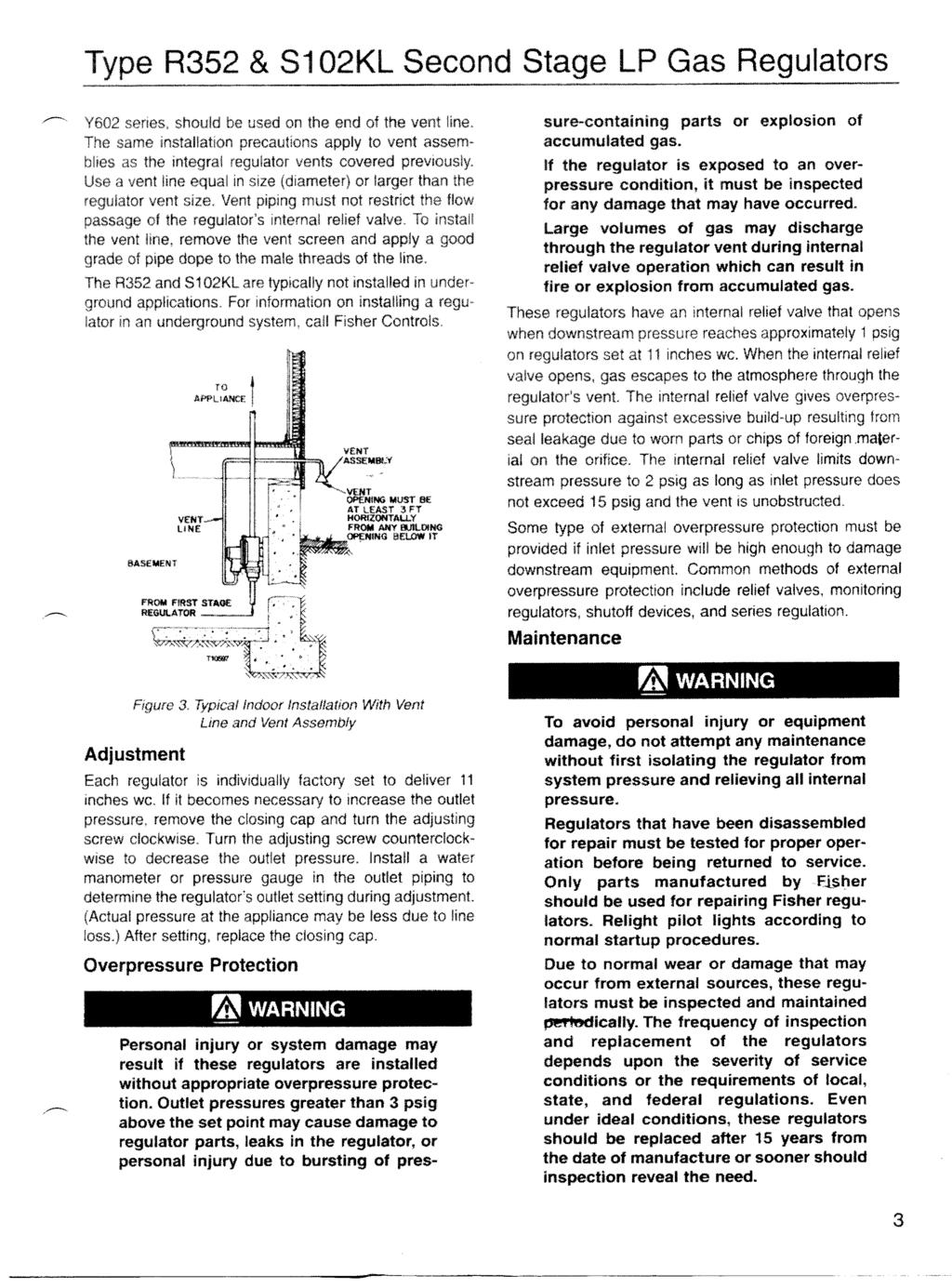
211
212
213 Fisher Controls Low Pressure Second-Stage & Integral 2-Stage LP-Gas Regulators Type R400 & R500 R400 & R500 MCK /99 Reguladores de Baja Presión Para Gas-LP de Segunda Etapa y Dos Etapas Integradas Tipo R400 y R500 ADVERTENCIA Failure to follow these instructions or to properly install and maintain this equipment could result in an explosion and/or fire causing property damage and personal injury or death. Fisher equipment must be installed, operated, and maintained in accordance with federal, state, and local codes and Fisher instructions. The installation in most states must also comply with NFPA No. 54 and 58 standards. Only personnel trained in the proper procedures, codes, standards, and regulations of the LP-gas industry should install and service this equipment. THINGS TO TELL THE GAS CUSTOMER: 1. Point out the regulator s vent to the customer (or vent assembly or vent tube), and stress that this opening must remain unobstructed at all times. Tell the customer to be sure to check the vent opening after a freezing rain, sleet storm, or snow to make sure ice has not formed in the vent. 2. Show the customer the shutoff valve on the container. The customer should close this valve immediately if gas is smelled, appliance pilot lights fail to stay on or appear higher than usual, or any other abnormal situation occurs. 3. Tell the customer to call your company to service the regulator if the regulator vents gas or a leak develops in the system. Only a qualified gas serviceman should install or service the regulator. Introduction Scope of Manual This instruction manual covers installation and maintenance for the Types R422, R522 & R552 second stage low pressure regulators, and the Type R532 integral 2-stage unit containing a first stage regulator on the inlet. These low pressure regulators have an integral high capacity internal relief valve. Inlet and outlet pressure taps are standard, making pressure testing easier. Description These regulators are designed for low pressure (inches of water column) vapor service and are not to be used for liquid service. The outlet pressure setting is normally 11 inches wc. Integral 2- stage (reducing container pressure to 11 inches wc) are normally painted GRAY, while second-stage regulators (reducing first stage pressure to 11-inches wc) are painted PALM GREEN. The units differ in construction and capacity rating. El no cumplir con estas instrucciones o no instalar y dar mantenimiento apropiado a este equipo puede resultar en una explosión y/o incendio, resultando en daños, heridas, o la muerte. Los reguladores Fisher deben instalarse, operarse y recibir mantenimiento de acuerdo con las regulaciones, leyes y códigos federales, estatales y municipales, e instrucciones de Fisher. En la mayoría de los estados, la instalación debe cumplir, también, con los estándares NFPA 54 y 58. Sólo personal entrenado en los procedimientos, códigos, estándares y regulaciones apropiadas para la industria de gas LP debe instalar y dar servicio a este equipo. QUE DEBE INFORMARLE AL USUARIO: 1. Muestre al cliente la ventila del regulador (el ensamble de la ventila o la tubería de la ventila), y haga énfasis en que esta abertura debe estar siempre libre de obstrucciones. Indique al cliente que es necesario que cheque la ventila después de una nevada, granizada o tormenta de agua congelada, para asegurarse de que no se formó hielo en la ventila. 2. Muestre al cliente el contenedor de la válvula para apagar el regulador y adviértale que debe cerrarla de inmediato, en caso de oler a gas, que exista falla en el encendido de los pilotos o se vean de mayor tamaño que el normal, o si ocurre cualquier situación anormal. 3. Indique al cliente que es necesario solicitar a la compañía una visita de servicio si el regulador registra una fuga de gas o si existe una gotera en el sistema. Sólo una persona calificada debe instalar o dar servicio al regulador. Introducción Alcance de este Manual Este manual de instrucciones cubre la instalación y mantenimiento del regulador de baja presión de segunda etapa Tipo R422, R522 y R552 y los reguladores de 2-etapas integradas tipo 532 que incluye un regulador de 1ra. etapa. Estos reguladores de baja presión disponen de una válvula interna de alivío de alta capacidad. La entrada y la salida disponen de tomas para medir la presión. Descripción Estos reguladores están diseñados para servicio de vapor en baja presión (pulg. de columna de agua), y no debe usarse para líquidos. El regulador es ajustado en fabrica a 11-pulgadas de c.a. (27.4 milibares). Los reguladores de 2-etapas integradas (reducen presión del contenedor a 11-pulg. de c.a. (27.4 milibares) son de color GRIS, mientras que los reguladores de segunda-etapa (que reducen de una presión de 1ra. etapa a 11-pulgadas de c.a. son VERDE PALMA. Los reguladores difieren en construcción y capacidades de flujo. D450072T012 1
214 Fisher Controls Specifications Table 1 lists the specifications for the regulator. Contact the factory if the regulator is to be used on any service other than LP-gas, natural gas, or air. Second-Stage regulators are limited to 10 psig inlet pressure and must be used with a first-stage regulator. Especifícaciones R400 & R500 La tabla 1 lista las especificaciones para este regulador. Contacte a la fábrica si al regulador va a darse un servicio distinto a gas LP, gas natural, o aire. Los reguladores de 2-etapas estan limitados a 10 psig (0.69 bares) de presión de entrada, por lo que deben utilizarse con reguladores de 1ra.-etapa. Table 1 Tabla 1 TYPE MAX. INLET NU MB ER TYPE OF SERVICE PRESSURE [MODELO] [SERVICIO] [MAX. PRESION DE ENT R ADA] S IZ E, INCH, F NPT [T AMAÑO, PU LGADAS, CONEXION NPT HE M B R A] INLET CONNECTION CONE XION DE ENTRADA OU T L E T CONE CCT ION CONE XION DE SALIDA SECOND-STAGE 10 PSIG* R422 3/4" 3/4" [SEGUNDA ETAPA] [0.69 Bares] VAPOR CAPACIT Y, BTU/HR P R OPANE *** [CAPACIDAD DE VAPOR EN BTU/HR P R OPANO ***] 2,025,000 R522 SECOND-STAGE [SEGUNDA ETAPA] 10 PSIG* [0.69 Bares] 1/4", 1/2", 3/4" 1/2" 875,000 3/4" 1,375,000 INTEGRAL TWO-STAGE 250 PSIG* 1/2" 685,000 R532 1/4" [INTEGRAL DE DOS ETAPAS] [17.24 Bares] 3/4" 1,100,000 R552 SECOND-STAGE [SEGUNDA ETAPA] 10 PSIG* [0.69 Bares] * Body inlet pressure rating 250 psig ** Assumes first stage regulator failure *** Based on 10 psig inlet pressure and 20% droop for second and integral two-stage. 3/4" 3/4" 1,100,000 * El cuerpo soporta una presión de 250 PSIG (17.2 Bares) ** Asume falla en el regulador de 1ra. etapa. *** Basado en una presión de entrada de 10 psig (0.69 Bar) y 20% de caida y una unidad integrada de 2 etapas. Installation Instalación ADVERTENCIA The vent should be kept open to permit free flow of air into and out of the regulator. Protect the vent against the entrance of rain, snow, ice formation, paint, mud, insects, or any other foreign material that could plug the vent or vent line. LP-gas may discharge to the atmosphere through the vent. An obstructed vent which limits air or gas flow can cause abnormally high pressure that could result in personal injury or property damage. Failure to use a vent line on Indoor Installations can cause a hazardous accumulation of gas which could result in personal injury or property damage. Never use first stage (pounds to pounds) regulator on low pressure (inches of water column) service because personal injury or property damage could occur. Make sure gas flow through the regulator is in the same direction as the arrow on the body Inlet and Outlet connections are clearly marked. The installation should be adequately protected from vehicular traffic and damage from other external sources. La ventila deberá mantenerse abierta, para permitir que el aire fluya libremente dentro y fuera del regulador. Proteja la ventila contra la entrada de lluvia, nieve, hielo, pintura, mugre, insectos o cualquier otro material ajeno que pueda obstruir la ventila o la línea de alivío. Gas LP puede ser descargado a la atmósfera a través de la ventila. Una ventila obstruida limita el flujo de aire o gas, causando sobrepresiones que puede resultar en lesiones al personal o daño a la propiedad. Nunca use los reguladores de 1ra. etapa (kilos a kilos) en servicio de baja presión (milimetros de columna de agua), ya que pueden presentarse lesiones al personal y/o daño a la propiedad. Asegúrese de que el gas fluye a través del regulador en la misma dirección que las flechas del cuerpo del regulador las conexiones de entrada y salida están claramente indicadas. La instalación debe protegerse adecuadamente del tráfico vehicular y daño por causas externas. 2
215 Fisher Controls R400 & R500 Install the regulator so that any gas discharge through the vent or vent assembly is over 3-feet horizontally from any building opening below the level of discharge. Install the regulator high enough above ground level - at least 18 inches - so that rain splatter cannot freeze in the vent. Whether a protective hood is used or not, do not install the regulator in a location where there can be excessive water accumulation or ice formation, such as directly beneath a down spout, gutter, or roof line of building. A regulator installed outdoors without a protective hood must have its vent pointed vertically down, see figure 2, to allow condensate to drain. This minimizes the possibility of freezing and of water or other foreign material entering the vent and interfering with proper operation. Before installing the regulator, check for damage which might have occurred in shipment. Also check for and remove any dirt or foreign material which may have accumulated in the regulator body or the pipeline. Apply pipe compound to the male threads of the pipe. Some installations, such as in areas with heavy snowfall, may require a hood or enclosure to protect the regulator. Horizontally mounted regulators, such as found in single cylinder installations, must be installed beneath a protective cover. If possible, slope or turn the vent down sufficiently to allow any condensation to drain out of the spring case. Be careful that the slot in the hood or cover for the regulator s outlet piping does not extend too far and expose the vent to the elments. By code, regulators installed indoors have limited inlet pressure, and they require a vent line to the outside of the building, see figure 3. A vent assembly, such as Fisher Y602 series, should be used on the end of the vent line. The same installation precautions apply to vent assemblies as the integral regulator vents covered previously. Use a vent line equal in size (diameter) or larger than the regulator vent. Vent piping must not restrict the flow passage of the regulator s internal relief valve. To install the vent line, remove the vent screen and apply a good grade of pipe dope to the male threads of the line. Underground container systems require a vent tube to prevent water Instale el regulador de tal manera que las descargas de gas a través de la ventila o del ensamble de la ventila queden a más de 3 pies (1 metro) de cualquier abertura que tenga el edificio abajo del nivel de la descarga. Instale el regulador a suficiente altura sobre el nivel del piso por lo menos 18 pulgadas (45 cm) para que la lluvia que salpique no llegue a congelarse en la ventila. Ya sea que use protector o no, no instale el regulador donde exista excesiva acumulación de agua, formación de hielo, como puede ser bajo una llave de agua, gotera o línea de desague. Si se instala un regulador en el exterior sin casco protector, deberá colocarse la ventila en forma vertical hacia abajo, ver figura 2, para permitir que drene cualquier condensación. Así se minimiza la posibilidad de congelamiento y de que entre a la ventila agua o cualquier otro material ajeno, interfiriendo con la operación adecuada del equipo. Antes de instalar el regulador, verifique que no exista daño que pueda haber ocurrido durante el embarque. También cheque y quite cualquier sucio o materia ajena que pueda haberse acumulado en el cuerpo del regulador o en la tubería. Aplique compuesto para tubería en los extremos machos de la tubería. En algunas instalaciones, como las que se hacen en áreas con nevadas pesadas pueden requerir de un casco o escudo para proteger el regulador. Los reguladores montados en forma horizontal, como los que se encuentran en las instalaciones de un solo cilindro, deben instalarse bajo una cubierta protectora. Si es posible, voltee la ventila hacia abajo lo suficiente para permitir que cualquier condensado drene hacia fuera del contenedor del resorte. Tenga cuidado en que el casco o la cubierta de la salida del regulador no se extienda demasiado lejos y la ventila quede expuesta a los elementos. Por código, los reguladores instalados en interiores deben tener una presión de entrada limitada y requieren de una línea de ventilación hacia el exterior del edificio, vea figura 3. Un ensamble de ventila, como el Fisher serie Y602, debe usarse al final de la línea de ventilación. Las mismas precauciones de instalación aplican a los ensambles de las ventilas como a las ventilas integrales del regulador, ya descritas. Use una línea de venteo del mismo diámetro o mayor que la salida del alívio. La tuberia de venteo no debe limitar el flujo de gas de la válvula de alívio interno del regulador. Para instalar la ventila, remueva la malla de la ventilla, aplique compuesto de tuberia a la rosca de la tuberia. TO APPLIANCE AL EQUIPO SALIDA DEL ALIVIO / MALLA DE PROTECCION VENT LINE LINEA DE ALIVIO BASEMENT SOTANO FROM FIRST - STAGE REG. DEL REGULADOR DE 1RA. ETAPA VENT OPENING MUST BE AT LEAST 3-FT HORIZONTALLY FROM ANY BUILDING OPENING BELOW IT. APERTURA DEBE ESTAR A 1 METRO DE CUALQUIER APERTURA DEBAJO DE ELLA Figure 2. Point Vent Down on Outdoor Installations Figura 2. Coloque la Ventila hacia abajo en Instalaciones Exteriores 3 Figure 3. Typical Indoor Installation With Vent line and Vent Assembly Figura 3. Instalació n interior con linea de alivio y ensamble de alívio
216 Fisher Controls from entering the regulator spring case, see figure 4. Remove the vent screen and install a vent tube. The vent tube must be run from the regulator vent to above the maximum water table. The vent tube opening must terminate at the extreme top inside of the dome cover. Maintain drainage away from the dome at all times. For further information on underground installations, write for a copy of Underground LP-Gas Systems: Suggested Installation, Inspection, available from The National Propane Gas Association, 1600 Eisenhower Lane, Suite 100, Lisle, IL R400 & R500 Los sistemas subterrá neos requieren de una linea de venteo para impedir que el agua entre al contenedor del resorte del regulador, ver figura 4. Quite la pantalla de la ventila e instale la linea con los mismos criterios ya mencionados. La linea de venteo debe correr desde la ventila hasta un lugar por encima del registro má ximo de agua. La abertura de este tubo debe terminar en el extremo superior de la tapa. Asegú rese que la tapa del regulador está firme y libre de drenaje a todo tiempo. Para mayor informació n sobre instalaciones subterrá neas, pida una copia de Instalació n e Inspecció n de Sistemas de Gas Subterrá neos, disponible en The National Propane Gas Association, 1600 Eisenhower Lane, Suite 100, Lisle, Il 60532, USA. GRADE GROUND DOWNWARD AND AWAY AROUND HOUSING DOME. THIS PREVENTS WATER COLLECTING AND RUNNING INTO OR STANDING AROUND HOUSING DOME. (EL TERRENO DEBE TENER INCLINACION DE TAL MANERA QUE EL AGUA NO SE ACUMULE Y SE ALEJE DE LA CUBIERTA PROTECTORA) END OF REGULATOR VENT TUBE LOCATED AT TOP INSIDE OF HOUSING DOME COVER. (EL FINAL DE LA LINEA DE VENTEO DEBE ESTAR POR ENCIMA DEL BORDE DE LA CUBIERTA) MINIMUM MINIMO (5.3 cm.) REGULATOR ADJUSTMENT CLOSURE CAP MUST BE TIGHT (TAPA DE AJUSTE DEL RESORTE DEBE ESTAR APRETADA FIRMEMENTE) WATER MARK LEFT IN HOUSING DOME AT LEVEL ABOVE REGULATOR VENT, OR END OF VENT TUBE REQUIRES REPLACEMENT OF REGULATOR, THEN CORRECT INSTALLATION. (SI LA LINEA DE AGUA ESTA POR ENCIMA DEL VENTEO DEL REGULADOR O DE LA LINEA DE VENTEO, EL REGULADOR DEBERA SER CAMBIADO Y LA INSTALACION CORREGIDA) Figure 4. Regulators Installed on Underground Installations Require a Vent Tube Figura 4. Reguladores instalados En Una Instalació n Subterrá nea Requieren Linea de Venteo Adjustment Each regulator is indivually factory set to deliver 11 inches wc. If it becomes necessary to increase the outlet pressure, remove the closing cap and turn the adjustment screw clockwise. Turn the adjusting screw counterclockwise to decrease the outlet pressure. The outlet pressure plug may be removed using a 7/16 hexagon wrench. The plug can be removed with pressure on the outlet of the regulator. Install a water manometer or pressure gauge to determine the regulator s outlet setting during adjustment, (Actual pressure at the appliance may be less due to line loss.) After setting, reinstall the pipe plug and replace the closing cap. Check the plug for leakage. Inlet pressure may be checked using the inlet pressure gauge tap and a pressure gauge. Remove the plug using a 7/16 wrench. The plug can be removed with pressure on the inlet of the regulator. Overpressure Protection Personal injury or system damage may result if these regulators are installed without appropiate overpressure protection. Outlet pressures greater than 3 psig above the set point may cause damage to regulator parts, leaks in the regulator, or personal injury due to bursting of pressure-containing parts or explosion of accumulated gas. If the regulator is exposed to an overpressure condition, it must be inspected for damage that may have occurred. 4 Ajuste Cada regulador se ajusta en forma individual en la fá brica a 11 pulgadas de columna de agua (69.6 milibares). Si es necesario aumentar la presió n de salida, quite la tapa y gire el tornillo de ajuste en el sentido de las manecillas del reloj; Si lo que se desea es disminuir la presió n, ajuste el tornillo girá ndolo en sentido contrario a las manecillas del reloj. El tapó n de presió n de salida puede removerse usando una llave hexagonal de 7/16. El tapó n puede removerse cuando existe presió n en la salida del regulador. Instale un manó metro de agua o de presió n para determinar el ajuste de la salida del regulador. (La presió n real en el equipo puede ser menor debido a pé rdida en la línea). Completado el ajuste, reinstale el tapó n de prueba Asegú rese de que no hay fugas en el tapó n. La presió n de entrada puede verificarse usando un manó metro. Remueva eltapó n con una llave de 7/16 ; puede quitarse con presió n en la entrada del regulador. Protección Contra SobrePresiones En caso de que estos reguladores se instalen sin una protección por sobrepresiones apropiadas, daños al sistema o a personas pudiera ocurrir. Una presión de salida mayor a 3 psig (0.2 bar) por encima del nivel de ajuste puede causar daño a partes internas del regulador, fugas en el regulador o daño al personal por explosión de partes presurizadas o del gas acumulado. Si el regulador es sometido a
217 Fisher Controls Large volumes of gas may discharge through the regulator vent during internal relief valve operation which can result in fire or explosion from accumulated gas. All of the regulators have an internal relief valve that opens when downstream pressure reaches approximately 1 psig on regulators set at 11 inches wc. When the internal relief valve opens, gas escapes to the atmosphere through the regulator s vent. The internal relief valve gives overpressure protection against excessive buildup resulting from seal leakage due to worn parts or chips or foreign material on the orifice. Some type of external overpressure protection must be provided if inlet pressure will be high enough to damage downstream equipment. Common methods of external overpressure protection include relief valves, monitoring regulators, shutoff devices, and series regulation. The internal relief valve on second-stage and integral two-stage regulators with 1 inch vent (Type R400 series) and 3/4 inch vent (R500 series) limits downstream pressure to 2 psig as long as inlet pressure does not exceed the values in table 1 and the vent is unobstructed. Maintenance To avoid personal injury or equipment damage, do not attempt any maintenance or disassembly without first isolating the regulator from system pressure and relieving all internal pressure. Regulators that have been disassembled for repair must be tested for proper operation before being returned to service. Only parts manufactured by Fisher should be used for repairing Fisher regulators. Relight pilot lights according to normal startup procedures. Due to normal wear or damage that may occur from external sources, these regulators must be inspected and maintained periodically. The frequency of inspection and replacemnet of the regulators depends upon the severity of service conditions or the requirements of local, state, and federal regulations. Even under ideal conditions, these regulators should be replaced after 15 years from date of manufacture or sooner should inspection reveal the need. Visually inspect the regulator each time a gas delivery is made for: 1. Improper installation. 2. Plugged or frozen vent. 3. Wrong regulator or no regulator in the system. 4. Internal or external corrosion. 5. Age of the regulator. 6. Any other condition that could cause the uncontrolled escape of gas. Failure to do the above could result in personal injury or property damage. Make sure the regulator vent, vent assembly, or vent tube does not become plugged by mud, insects, ice, snow, paint, etc. The vent screen aids in keeping the vent from becoming plugged, and the screen should be clean and properly installed. Replace any regulators that have had water in their spring case or show evidence of external or internal corrosion. Checking for internal R400 & R500 una sobrepresión, el mismo deberá inspeccionarse para verificar que no este dañado. Volúmenes grandes de gas pueden ser descargados a través de la ventila del regulador si la válvula de alivio interna opera, pudiendo resultar en incendio o explosión del gas acumulado. Todos los reguladores cuentan con una vá lvula de alivio interna que se abre cuando la presió n de salida alcanza aproximadamente 1 psig (69 milibares) en reguladores ajustados a 11 pulgadas ca (27.4 milibares). Cuando se abre, escapa el gas a la atmó sfera a travé s de la ventila del regulador. La vá lvula interna de alivio protege contra la sobrepresió n que resulte al sellar una fuga debido a partes desgastadas, basura o material ajeno que esté en el orificio. Debe darse protecció n externa contra la sobrepresió n, si la presió n interna puede ser tan alta que dañ e el equipo corriente abajo. Los mé todos comunes de protecció n externa contra la sobrepresió n incluyen: vá lvulas de alivio, reguladores de monitoreo, aditamentos para apagar el equipo y regulació n en serie. La vá lvula de alívio interno en los reguladores 2da. etapa e los integrados de 2-etapas con una ventila de 1 pulgada (Serie R400) y 3/4 de pulgada (Serie R500) limitan la presió n aguas abajo del regulador a 2 psig (0.13 bares) siempre que la presió n de entrada no supere los valores indicados en la tabla 1 y la ventila no este obstruida. Mantenimiento ADVERTENCIA Para evitar lesiones al personal o daño al equipo, no intente dar mantenimiento o desensamblar el regulador sin primero aislarlo del sistema de presión y aliviar toda la presión interna. Los reguladores que se han desarmado para reparación deben probarse antes de regresarlos a servicio. Sólo deben usarse partes de Fisher al reparar los reguladores Fisher. Encienda nuevamente los pilotos de acuerdo con los procedimientos estándar de arranque. En virtud de que puede ocurrir daño ocasionado por uso normal o por causas externas, es necesario inspeccionar y dar mantenimiento a este regulador en forma periódica. La frecuencia de la inspección y substitución de partes depende de la severidad de condiciones de operación y de los requerimientos de leyes y regulaciones locales, estatales y municipales. Aun en las condiciones ideales, es necesario reemplazar estos reguladores después de 15 años de la fecha de fabricación, o antes, si una inspección demuestra la necesidad de hacerlo así. Cada vez que se hace una entrega de gas, se debe inspeccionar visualmente el regulador. La revisió n debe incluir: 1. Instalació n apropiada del regulador. 2. Chequeo que la ventila no este obstruida. 3. Que no se haya removido el regulador y que sea el adecuado. 4. Que no exista corrosió n interna o externa. 5. Edad del Regulador. 6. Cualquier otra condició n que pudiera causar el escape nocontrolado de gas. El no llevar a cabo lo anterior puede resultar en lesiones al personal o dañ o a la propiedad. 5
218 Fisher Controls corrosion may require complete removal of the adjusting screw and shut down of the gas system. Closely examine regulators directly connected to the container valve by means of a solid POL adaptor (horizontal mounting) for signs of corrosion. Correct any improper installations. Older regulators are more likely to catastrophically fail because of worn or corroded parts. Replace regulators over 15 years of age; other service or environmental conditions may dictate replacement of the regulator before it becomes 15 years old, refer to Fisher Bulletin LP-32. These regulators have an internal inlet screen to help prevent foreign particles.003 across or larger from passing through the the regulator and into the downsteam appliances. Such foreign material can cause improper operation of both regulators and appliances. In most installations, the inlet screen will provide adequate filtration capacity over the life of the regulator. However, in installations with extreme debris contamination, it is possible for the filter screen to become blocked and stop or restrict the flow of gas. If this should occur, remove the four inlet fitting cap screws along with the inlet fitting and its o-ring. Remove the filter screen and clean or replace it. After installation of the filter screen, reinstall the inlet fitting, its o- ring, and the four inlet fitting cap screws. Leak test the inlet fitting flange. NOTE: The R522 inlet screen may be accessed by simply removing the inlet piping. Regulator Repair Regulators that have been disassembled for repair must be tested for proper operation before being returned to service. Only parts manufactured by Fisher should be used to repair Fisher regulators. Be sure to give the complete type number of the regulator when corresponding with the factory. R400 & R500 Asegú rese de que la ventila del regulador, el ensamble de la ventila o el tubo de la ventila nos encuentran obstruidos por mugre, insectos, hielo, nieve, pintura, etc. La pantalla de la ventila es un auxiliar para conservar la ventila limpia y bien instalada. Substituya cualquier regulador al que le haya caído agua en el contenedor del resorte o muestre evidencia de corrosió n interna o externa. Para hacer una inspecció n de corrosió n interna es necesaria la remoció n total del tornillo de ajuste y apagar completamente el sistema de gas. Examine cuidadosamente los reguladores que está n conectados directamente al contenedor de la vá lvula por medio de un adaptador só lido POL (montaje horizontal), para detectar algú n signo de corrosió n. Corrija cualquier instalació n no adecuada. Hay má s probabilidades de que fallen los reguladores de má s edad, debido al uso o a partes desgastadas. Substituya los reguladores de má s de 15 añ os de edad; y a aqué llos que por el uso o las condiciones medio ambientales deban substituirse antes de cumplir 15 añ os. Consulte el Boletín Fisher LP-32 para má s referencias. Estos reguladores cuentan con una pantalla interna que ayuda a prevenir que partículas ajenas de má s de.003 micras pasen al regulador y lleguen al sistema de flujo. Estos materiales ajenos pueden ocasionar operació n inadecuada, tanto en el regulador como en los equipos alimentados por gas. En la mayoría de las instalaciones, la pantalla interna puede brindar suficiente capacidad de filtració n durante la vida activa del regulador. Sin embargo, en instalaciones con demasiados desechos contaminantes es posible que la pantalla del filtro quede obstruida y detenga o restrinja el flujo de gas. Si esto llega a ocurrir, desconecte la linea de alimentació n, retire el filtro y límpielo. Cambie el filtro si no se puede limpiar o si esta dañ ado. Con cuidado, presione el filtro en la entrada hasta que toque el fondo. Reinstale las tuberias y cheque si existe alguna fuga. NOTA: El filtro de entrada del R522 puede ser removido removiendo la tuberia de entrada. Reparación de los reguladores A los reguladores que se hayan desensamblado para reparació n es necesario probarlos antes de reinstalarlo para operació n. Unicamente utilize refacciones Fisher para reparar sus reguladores Fisher. Por favor incluya el numero completo del regulador en sus comunicaciones con la fabrica. For further information, contact Fisher Controls International, LLC: P.O.Box 8004, McKinney, Texas 75069, USA WEB SITE: The contents of this publication are presented for informational purposes only, and while every effort has been made to ensure their accuracy, they are not to be construed as warranties or guarantee, expressed or implied, regarding the products or services herein or their use or applicability. Fisher Controls reserves the right to modify or improve the designs or specifications of such products at any time without notice. Fisher Controls International, Inc., 1990,1999; All Rights Reserved. Fisher, Fisher-Rosemount, and Managing The Process Better are marks owned by Fisher Controls International, Inc. or Fisher-Rosemount Systems, Inc. All other marks are the property of their respective owners. Para mayor informació n, favor comuniquese con Fisher Controls International, LLC: P.O.Box 8004 McKinney, Texas 75069, USA DIRECCION EN EL INTERNET: Toda la informació n aqui descrita es para efectos de informació n solamente, y se ha hecho el esfuerzo para que sea la la má s acertada, pero en ningú n caso constituye una garantia, expresa o implicita, en relació n a los productos o servicios aqui descritos. Fisher Controls se reserva el derecho de alterar o mejorar los diseñ os o especificaciones de los equipos aqui descritos sin previo aviso. Fisher Controls International, Inc., 1990, 1999; All Rights Reserved. Fisher, Fisher-Rosemount, y Managing The Process Better son marcas registradas y pertenecientes a Fisher Controls International, Inc. o Fisher-Rosemount Systems, Inc.Cualquier otra marca es propiedad de su respectivo dueñ o.
219 Type R522 Fisher Controls Installation Manual Type R522 and R522H Pressure Reducing Regulators October 1992 Form 5331 Introduction This installation manual covers the installation, startup, and adjustment procedures for Type R522 and R522H pressure reducing regulators. The Type R522 self-operated, spring-loaded regulator provides economical pressure-reducing control in a variety of service and industrial applications. The regulator can be used with a variety of gaseous fluids such as natural gas, manufactured gas, propane, or air. The Type R522 regulators have high capacity and factory adjustable internal relief to help minimize overpressurization of the downstream system. Any excess outlet pressure above the start-to-discharge point of the relief valve spring, moves the diaphragm off the relief valve seat, allowing excess pressure to bleed out through the screened spring case vent. Installation WARNING Personal injury, equipment damage, or leakage due to escaping accumulated gas or bursting of pressure-containing parts may result if this regulator is overpressured or is installed where service conditions could exceed the limits given in table 1. To avoid such injury or damage, provide pressure-relieving or pressure-limiting devices (as required by Title 49, Part 192, of the U.S. Code of Federal Regulations, by the National Fuel Gas Code Title 54 of the National Fire Codes of the National Fire Protection Association, or by other applicable codes) to prevent service conditions from exceeding those limits. Additionally, physical damage to the regulator could result in personal injury or property damage due to escaping gas. To avoid such injury and damage, install the regulator in a safe location. 1. Only personnel qualified through training and experience should install, operate, and maintain a regulator. Before installing a Type R522 regulator, check for damage which might have occurred in shipment. Also check for dirt or foreign matter which may have accumulated in the regulator body or in the pipeline. 2. The Type R522 may be installed in any position (vertical or horizontal). Apply a good grade of pipe compound to the male threads (being sure not to apply pipe compound to flow path of the pipe) of the pipe and install the regulator so that the flow is in the direction of the arrow cast on the body. Use approved piping procedures when installing the regulator. Table 1. Specifications Body Sizes And End Connection Style Inlet: 1/4, 1/2, and 3/4-inch NPT screwed Outlet: 1/2 and 3/4-inch NPT screwed Maximum Allowable Inlet Pressure (1) 250 psig (17 bar) Outlet Pressure Range (1) 4.5 inches w.c. to 15.5 psig (11.2 mbar to 1.1 bar) Allowable Outlet Pressures (1) Emergency (Casing): 20 psig (1.4 bar) Maximum Operating to Avoid Internal Part Damage: 3 psi (0.21 bar differential) above outlet pressure setting Orifice Sizes and Color Code R522: 1/8-inch (gray) R522H: 13/64-inch (tan) 1. The pressure/temperature limits in this manual, and any applicable code or standard limitations, should not be exceeded. Material Temperature Capabilities (1) 40 F to 160 F ( 40 C to 71 C) Fisher Controls International, Inc., 1992; All Rights Reserved
220 Type R522 Regulator Type number R522 R522H Table 2. Outlet Pressure Ranges Outlet Pressure Range 4.5 to 6 inches w.c. (11.2 to 15 mbar) 5.5 to 8 inches w.c. (13.7 to 20 mbar) 7.5 to 9.5 inches w.c. (18.7 to 23.7 mbar) 9.5 to 13 inches w.c. (23.7 to 32.5 mbar) 13 to 20 inches w.c. (32.5 to 50 mbar) 20 to 28 inches w.c. (50 to 70 mbar) 1 to 2.5 psig (70 to 172 mbar) 2.5 to 5.5 psig (172 to 379 mbar) 5.5 to 10.5 psig (379 to 724 mbar) 10.5 to 15.5 psig (724 to 1069 mbar) Control Spring Part Number T13588T0012 T13589T0012 T13590T0012 T13624T0012 T13592T0012 T13546T0012 T13593T0012 T13599T0012 T13600T0012 T13601T0012 Control Spring Color Code Red Yello w Olive Drab Purple Gray Orange Blue Green Red Yello w Key Description 1 Body 1/2-inch size 3/4-inch size 2 Inlet Fitting 1/4-inch size 1/2-inch size 3/4-inch size 3 Spring Case Assembly 4 Vent Screen 5 Retaining Ring 6 Control Spring 7 Orifice Tube Assembly 8* Orifice Tube O-Ring 9 Orifice Tube Screw 10 Diaphragm/Relief Valve Assembly 11 Closing 00061P08 12 Adjusting Screw 13 Spring Case Screw 14 Inlet Screw 15* Inlet O-Ring 16 Pipe Plug 19 Screw 21 Screw 22 Inlet Screen *Recommeded spare part. Figure 1. Type R522 Regulator Assembly WARNING A regulator may vent some gas to the atmosphere. In hazardous or flammable gas service, vented gas may accumulate, and cause personal injury, death, or property damage due to fire or explosion. Vent a regulator in hazardous gas service to a remote, safe location away from air intakes or any hazardous location. The vent line or stack opening must be protected against condensation or clogging. Under enclosed conditions, escaping gas may accumulate and be an explosion hazard. In these cases the vent should be piped away from the regulator to a safe location outdoors. While this information is presented in good faith and believed to be accurate, Fisher Controls does not guarantee satisfactory results from reliance upon such information. Nothing contained herein is to be construed as a warranty or guarantee, express or implied, regarding the performance, merchantability, fitness Fisher Controls 3. On outdoor installations, regulators installed with vents in positions other than vertically down require additional vent protection from the elements. Such protection may be with separate hood shields, or the Fisher Y602 Series vents. 4. Regulator operation within ratings does not preclude the possibility of damage from debris in the lines or from external sources. A regulator should be inspected for damage periodically and after any overpressure condition. 5. To adjust the regulator, monitor downstream pressure with a gauge during the adjustment procedure. To increase the outlet pressure, the adjustment screw (key 12, figure 1) must be turned clockwise. This requires removal of the closing cap (key 11, figure 1). To reduce the outlet pressure setting, turn the adjusting screw counter-clockwise. Do not adjust the spring to produce an outlet pressure setting above the limit stamped on the regulator. or any other matter with respect to the products, nor as a recommendation to use any product or process in conflict with any patent. Fisher Controls reserves the right, without notice, to alter or improve the designs or specifications of the products described herein. For information, contact Fisher Controls: Marshalltown, Iowa USA Sao Paulo Brazil Cernay France Singapore 0512 Printed in USA
221
222
223
224
225
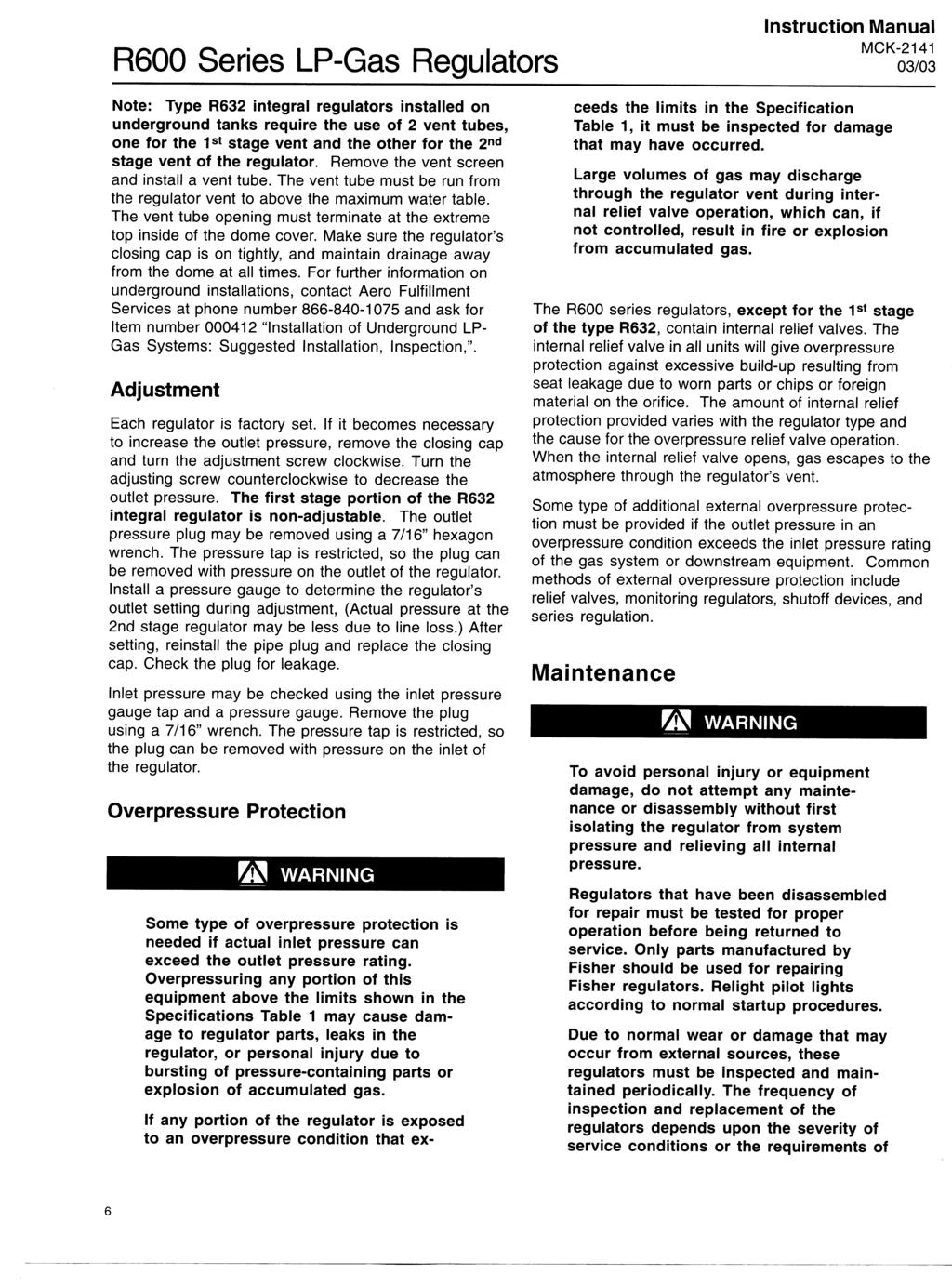
226
227
228

229 L4081A,B and L6081A,C Multiple Aquastat Controllers The L4081, L6081 Aquastat Controllers provide boiler water regulation in gas- or oil-fired hydronic heating systems. An immersion type liquid-filled sensing element actuates two snap switches. One switch operates as a high limit control. The other switch operates as a low limit and/or circulator control, depending on model. Controller may be mounted in any position and needs no leveling. Separate, easy-to-read calibrated dial and setpoint adjustment for each switch. Differential adjustment on low limit or circulator switch. All adjustments accessible inside front cover. Push-in terminals for quick connecting. Single sensing element for easy installation. Two spst snap switches (one spst and one spdt in L6081A,C) act independently at respective temperature settings. CONTENTS Specifications... 2 Ordering Information... 2 Installation... 4 Wiring... 5 Operation... 8 Settings... 8 Checkout... 9 J. H. Rev Honeywell Inc
230 L4081A,B/L6081A,C SPECIFICATIONS ORDERING INFORMATION Specifications IMPORTANT: The specifications given in this publication do not include normal manufacturing tolerances. Therefore, this unit may not exactly match the listed specifications. Also, this product is tested and calibrated under closely controlled conditions, and some minor differences in performance can be expected if those conditions are changed. TRADELINE MODELS TRADELINE models are selected and packaged to provide ease of stocking, ease of handling, and maximum replacement value. TRADELINE model specifications are the same as those of standard models except as noted below. TRADELINE MODEL AVAILABLE: L6081A Multiple Aquastat Controller. ADDITIONAL FEATURES: TRADELINE pack with cross reference label and special instruction sheet, well adapter, tube of heat-conductive compound, and setting stops. STANDARD MODELS Refer to Table 1 for model specifications. RANGES: High Limit: 130 F (54.5 C) to 240 F (115.5 C). Stops burner if boiler temperature exceeds setpoint. Low Limit: 110 F (43.5 C) to 220 F (104.5 C). Controls burner during thermostat off periods to maintain boiler water temperature. Circulator: 110 F (43.5 C) to 220 F (104.5 C). Permits circulator operation only if boiler water temperature exceeds low limit setting. Model Number Insertion Type a Switching L4081A Well Spst Hi Limit L4081B Well Spst Hi Limit L6081A Well Spst Hi Limit L6081C b Well Spst Hi Limit TABLE 1 MODEL SPECIFICATIONS. High Temperature Side Action on Temperature Rise to Setpoint Breaks Breaks Breaks Breaks Switching Spst Low Limit Spst Circulator Spdt Low Limit/Circulator Spdt Low Limit/Circulator Low Temperature Side a Some models are shipped less well; if well is needed, refer to form for ordering information. b Device is less case and cover. Action on Temperature Rise to Setpoint Breaks Makes Breaks R-B Makes R-W Breaks R-B Makes R-W Ordering Information When purchasing replacement and modernization products from your TRADELINE wholesaler or distributor, refer to the Tradeline Catalog or price sheets for complete ordering number, or specify 1. Order number. 2. Accessories, if desired. 3. Order additional system components and system accessories separately. If you have additional questions, need further information, or would like to comment on our products or services, please write or phone: 1. Your local Home and Building Control Sales Office (please check the white pages of your phone directory). 2. Home and Building Control Customer Logistics Honeywell Inc., 1885 Douglas Drive North Minneapolis, Minnesota (612) In Canada Honeywell Limited/Honeywell Limitée, 740 Ellesmere Road, Scarborough, Ontario M1P2V9. International Sales and Service Offices in all principal cities of the world. Manufacturing in Australia, Canada, Finland, France, Germany, Japan, Mexico, Netherlands, Spain, Taiwan, United Kingdom, U.S.A
231 L4081A,B/L6081A,C SPECIFICATIONS SCALE MARKINGS: For Fahrenheit Models: High Limit:160, 180, 200, 220 F. Low Limit or Circulator: 120, 140, 160, 180, 200 F. For Celsius Models: High Limit: 55, 65, 75, 85, 95, 105 C. Low Limit or Circulator: 45, 55, 65, 75, 85, 95 C. DIFFERENTIALS: High Limit: 10 F (5.5 C) nominal. Low Limit or Circulator: L6081A,C: F ( C) adjustable. L4081A,B: 10 F (5.5 C) nominal or F ( C) adjustable. MAXIMUM PRESSURE RATING: Well Mounted: 200 psi (1380 kpa). Direct Immersion: 100 psi (690 kpa). MAXIMUM AMBIENT TEMPERATURE: At Switches: 150 F (65.5 C). At Sensing Element: 265 F (129.5 C). JUMPER: The Push-in Field Addable Jumper (included) can be inserted in slot between R-R terminals to simplify wiring. (Insert with formed legs up in slot labeled jumper. Be sure to insert fully to positive stop.) MOUNTING DIMENSIONS: See Fig. 1 and 2. APPROVALS: Underwriters Laboratories Inc. Listed (L4081A,B and L6081A): File No. MP466, Guide No. MBPR. Component Recognized (L6081C): File No. MP466, Guide No. MBPR2. Canadian Standards Association Component Recognized (L4081A,B and L6081A): File No. LR1620, Guide No. 400-E-0. Fig. 1 L4081A,B and L6081A mounting. MAXIMUM INSERTION 3-1/2 (89) INSULATION DEPTH, 1-1/2 (38) OR 3 (76) WELL-CLAMP SCREW 7/8 IN. (22 MM) DIA. KNOCKOUT FOR 1/2 IN. (12.5) CONDUIT (6) 1-3/16 (30) 3/4-14 NPT OR 1/2-14 NPT 1-13/64 (30.5) (2) 1-13/64 (2) (30.5) 3-7/8 (98.5) 3/4 (19) (2) 1-3/8 (35) (2) 1-13/16 (4) (46) 2-3/64 (63) 4-3/32 (125.5) 2-11/16 (68) M
232 L4081A,B/L6081A,C SPECIFICATIONS INSTALLATION Fig. 2 L6081C mounting dimensions in in. (mm). 1/4 (6.5) 7/8 (22) 3-5/8 (92) ELECTRICAL RATING (A): See Table 2. TABLE 2 ELECTRICAL RATINGS. 120 Vac 240 Vac Full Load Locked Rotor Millivoltage 0.25A at 1/4 to 12 Vdc Plus ignition transformer load of 360 VA. Maximum connected load 2000 VA. WELL SPUD LENGTH: 1-1/2 in. (38 mm). Longer spud for 3 in. (76 mm) of insulation available. SPUD THREAD SIZE: 3/4-14 NPT standard. 1/2-14 NPT available. OPTIONAL SPECIFICATIONS: Plastic coating on immersion well to minimize electrolytic deterioration (on some with well models). Celsius scale on L4081A. ACCESSORY: Setting Stop. Used to prevent turning setting knob beyond a predetermined point. 1-5/16 (33.5) 2-1/4 (57) 11/16 (17.5) 2-1/8 (54) 2-7/16 (62) M8845 Installation WHEN INSTALLING THIS PRODUCT Read these instructions carefully. Failure to follow them could damage the product or cause a hazardous condition. 2. Check the ratings given in the instructions and on the product to make sure the product is suitable for your application. 3. Installer must be a trained, experienced service technician. 4. After installation is complete, check out product operation as provided in these instructions. CAUTION Disconnect power supply before installation to prevent electrical shock or equipment damage. These devices can be installed in any position. Proper location, sizing, and threaded boiler tapping are required. NOTE: Maximum pressure rating for these models is 200 psi (1380 kpa). Maximum permissible ambient temperature at sensing bulb is 265 F (129.5 C); at switches, 150 F (65.5 C). The L6081C is without enclosure or well assembly. MOUNTING Follow instructions provided by system manufacturer if available. Otherwise, proceed as follows: 1. Drain the boiler if system is filled with water. 2. Place front of controller down on a horizontal surface and gently raise the sensing bulb until it is at a right angle with the back of the case and centered with the large hole in the case. This requires bending the capillary tube, but be sure to make no sharp bends and no bends near the bulb. NOTE: Some models have an adjustable tubing length to 3 in. (76 mm). In these models, extra tubing inside the case can be pulled out, if needed. See Fig Adjust the position of the bulb so that bulb projects 4-7/8 in. (124 mm) from back of case for immersion well designed for 1-1/2 in. (38 mm) insulation; or 6-3/8 in. (162 mm), if designed for 3 in. (76 mm) insulation. If this requires bending the tube inside the case, insert end of

233 L4081A,B/L6081A,C INSTALLATION WIRING Fig. 3 Adjusting the capillary length. 7. Loosen the wall clamp screw three or four turns; move the screw in and out and note how it moves the well clamp. See Fig. 4. Loosen the screw enough so that when the screw is pushed inward, the T-shaped clamp guide is at the far end of the slot in the case. 1 CAUTION: EXCESSIVE HANDLING OR SHARP BENDS CAN DAMAGE THE CAPILLARY. 2 3 Fig. 4 L6081A with cover removed to show adjustments. 8. Mount the case on the well spud in any position that facilitates wiring. With the case in final position, carefully insert the sensing bulb into the well until the case slips over STRIP GAUGE WELL CLAMP SCREW SENSING ELEMENT IS FACTORY FORMED FOR 1.5 INCH INSULATION WELL ASSEMBLIES. FOR 3 INCH INSULATION WELL ASSEMBLIES, PULL OUT SUFFICENT CAPILLARY TO ASSURE THAT THE CAPSULE BOTTOMS IN THE WELL. STRAIGHTEN CAPILLARY SUFFICENTLY SO IT DOES NOT INTERFERE WITH INSERTING THE CAPSULE INTO THE WELL. M8882 LOW LIMIT/ CIRCULATOR DIFFERENTIAL ADJUSTMENT LOW LIMIT SETPOINT ADJUSTMENT index finger through the hole and carefully mold the tube into the correct shape as you gently pull (or push) the bulb to the correct position. The bulb must project the right distance so that after the case is installed, the spring force of the capillary tube holds the bulb against inner end of the well for good thermal contact. The tube must be straight for at least 3/8 in. (9.5 mm) inside the case so the end of the well spud does not strike the coiled tube and pull the bulb away from contact with the inner end of the well. 4. Remove the plug from a properly located boiler tapping. 5. Apply pipe dope sparingly to the threads of the well; then screw the well tightly into the boiler tapping. 6. Fill the system with water, then carefully examine around the threads for leakage. Tighten the well if necessary to stop any leakage. CAUTION Disconnect power supply to prevent electrical shock or equipment damage. Use care to avoid strain on control case when using cable or conduit. WARNING CAN CAUSE PROPERTY DAMAGE, SEVERE INJURY OR DEATH. This Product is for use only in a system with a pressure relief valve. HIGH LIMIT SETPOINT ADJUSTMENT JUMPER SLOT M8848 the end of the well spud and fits squarely against the shoulder of the spud. NOTE: Open the clamp to receive the spud by pushing in the well clamp screw. 9. While holding the case in the correct position, firmly tighten the well clamp screw. Wiring All wiring must comply with applicable codes and ordinances. See cover insert for electrical load ratings. Refer to Fig. 5 through 9 for typical wiring diagrams. Use the following procedure when connecting wires to the B tab terminals (Fig. 4): 1. Connect no. 14, 16, or 18 solid, or no. 14 or 16 unistranded wire to the tab terminals. 2. Strip insulation from the end of each wire. 3. Use the included wire nut from the bag assembly to connect the tab terminal connector to the wire. 4. Connect the wire to the tab terminal. JUMPER When using the controller field addable jumper (Fig. 4), connect terminals R-R. When the jumper is added, make sure that the two prongs of the jumper face the center of the controller
234 L4081A,B/L6081A,C WIRING Fig. 5 L4081A used with gas burner (line voltage limit). Fig. 6 L4081B used to prevent circulator operation with boiler water temperature below low limit setting. L2 1 L1 (HOT) L4081A 2 L2 1 CIRCULATOR HIGH LIMIT B R B R LOW LIMIT VR8300 LOW VOLTAGE GAS VALVE L1 (HOT) 2 L4081B HIGH LIMIT B R W R CIRCULATOR CIRCULATOR RELAY 24V THERMOSTAT BURNER CONTROL CIRCULATOR MOTOR T T RA832A SWITCHING RELAY 1R X 1R2 X JUMPER REMOVED 1 2 JUMPER REMOVED POWER SUPPLY. PROVIDE DISCONNECT MEANS AND OVERLOAD PROTECTION AS REQUIRED. B IS A TAB TERMINAL. M POWER SUPPLY. PROVIDE DISCONNECT MEANS AND OVERLOAD PROTECTION AS REQUIRED. 2 B TERMINALS ARE TAB TERMINALS. M8846 Fig. 7 L4081A used with burner cycled from the water temperature. L2 1 L1 (HOT) PILOTSTAT CONTROL CIRCULATOR 2 L1 (HOT) L2 1 24V THERMO- STAT R1 HIGH LIMIT B R B R LOW LIMIT L4081A T T 1R GAS VALVE RA89A SWITCHING RELAY 1 POWER SUPPLY. PROVIDE DISCONNECT MEANS AND OVERLOAD PROTECTION AS REQUIRED. 2 B TERMINALS ARE TAB TERMINALS. M
235 L4081A,B/L6081A,C WIRING Fig. 8 L4081A used with oil burner. L2 1 L1 (HOT) L1 (HOT) BLACK 1 24V THERMOSTAT CIRCULATOR R1 HIGH LIMIT 2 B R L4081A B R LOW LIMIT T T WHITE OIL PRIMARY CONTROL JUNCTION BOX L2 T 1R2 X T 1R X RA832A SWITCHING RELAY 1 2 POWER SUPPLY. PROVIDE DISCONNECT MEANS AND OVERLOAD PROTECTION AS REQUIRED. B TERMINALS ARE TAB TERMINALS. M8786 Fig. 9 L6081A used with oil burner. R4184D PROTECTORELAY CONTROL JUNCTION BOX SS BLACK 1K 1K2 ORANGE BURNER MOTOR CAD CELL F SOLID STATE SWITCH SAFETY SWITCH HEATER 1K1 OIL VALVE IGNITION F WHITE L2 1 L1 (HOT) CIRCULATOR 24V THERMOSTAT R1 B R 2 B R W T 1R T RA89A SWITCHING RELAY 1 L6081A JUMPER ADDED POWER SUPPLY. PROVIDE DISCONNECT MEANS AND OVERLOAD PROTECTION AS REQUIRED. 2 B TERMINALS ARE TAB TERMINALS. M
236 L4081A,B/L6081A,C OPERATION SETTINGS Operation HIGH LIMIT The high limit opens and turns off the burner when the water temperature reaches the set point. The high limit automatically resets after the water temperature drops past the set point and through the 10 F (5.5 C) differential. LOW LIMIT AND CIRCULATOR On a temperature rise, with the adjustable differential at the minimum setting of 10 F (5.5 C) (also applies to fixed 10 F (5.5 C) differential models), the burner circuit (R-B) breaks and the circulator circuit (R-W) makes at the control setpoint. On a temperature drop of 10 F (5.5 C) below the setpoint, the R-B circuit makes and the R-W circuit breaks. At any differential setting greater than 10 F (5.5 C), the R-B make temperature and R-W break temperature remains the same control setting minus 10 F (5.5 C). The R-B break and R-W make temperature are the setpoint temperature plus the difference between the differential setting and 10 F (5.5 C). EXAMPLES: L4081A: Setpoint of 140 F (60 C); differential set at 25 F (14 C). On a temperature rise, the switch breaks at 155 F (68.5 C). On a temperature fall, the switch makes at 130 F (54.5 C). L4081 B: Setpoint of 140 F (60 C); differential set at 25 F (14 C). On a temperature rise, the switch makes at 155 F (68.5 C). On a temperature fall, the switch breaks at 130 F (54.5 C). L6081A,B: Setpoint of 140 F (60 C); differential set at 25 F (14 C). On a temperature rise, R-B breaks and R- W makes at 155 F (68.5 C). On a temperature fall, R- B makes and R-W breaks at 130 F (54.5 C). Settings Because heating systems differ, follow the boiler manufacturer recommendations when selecting temperature settings. Study the applicable chart in Fig. 10, which shows the switching response to temperature changes. With cover off, set the high limit adjustment at the temperature desired but not higher than recommended by the boiler manufacturer (Fig. 4). Set the low limit and/or circulator adjustment to obtain temperature desired but not less than 20 F (11 C) below the high limit setting. The differential adjustment applies to only the low-limit and/or circulator switch(es). Minimum differential adjustment provided is 10 F (5.5 C) nominal; maximum is 25 F (14 C) nominal. Set as desired. SETTING STOP Install the Setting Stop on the adjusting knob to prevent turning the knob beyond a predetermined point. Fig. 11 shows stops installed on knob of high limit switch to prevent setting higher than 180 F (82 C). To install the setting stop, proceed as follows: 1. Turn knob to the setting that is to be established as the limit. 2. Place setting stop over knob in position to arm of setting stop (after stop is pressed into place) strikes projection A and prevents turning the knob beyond the desired limit setting. 3. Press setting stop tightly onto knob so its inner teeth securely engage knob. 4. Turn knob back and forth several times to make sure stop functions properly. 5. When all settings are made, replace the cover
237 L4081A,B/L6081A,C SETTINGS CHECKOUT Fig. 10 Charts showing switching response to temperature changes. Fig. 11 Setting stop shown in position to limit high limit setting to 180 F (82 C). 240 F (116 C) KNOB SET AT 180 F (82 C) HIGH LIMIT SETTING 10 F (5.6 C) DIFFERENTIAL SWITCH BREAKS ON RISE. BURNER TURNS OFF. SWITCH MAKES ON FALL. BURNER OPERATES ON A CALL FOR HEAT. SETTING STOP SETTING STOP ARM LOW LIMIT SETTING 25 F (13.9 C) DIFFERENTIAL 10 F (5.6 C) DIFFERENTIAL SWITCH BREAKS ON RISE. (25 F (13.9 C) DIFFERENTIAL). SWITCH BREAKS ON RISE. (10 F (5.6 C) DIFFERENTIAL). SWITCH MAKES ON FALL. BURNER ON. PROJECTION "A" F (43 C) L4081A 1 SCALE MARKINGS IN FAHRENHEIT ONLY. M F (116 C) HIGH LIMIT SETTING CIRCULATOR SETTING 10 F (5.6 C) DIFFERENTIAL 25 F (13.9 C) DIFFERENTIAL 10 F (5.6 C) DIFFERENTIAL SWITCH BREAKS ON RISE. BURNER TURNS OFF. SWITCH MAKES ON FALL. BURNER OPERATES ON CALL FOR HEAT. SWITCH MAKES ON RISE. (25 F (13.9 C) DIFFERENTIAL). SWITCH MAKES ON RISE. (10 F (5.6 C) DIFFERENTIAL). SWITCH BREAKS ON FALL. CIRCULATOR OFF. Checkout After completing installation and controller settings, operate the system. Carefully observe the operation of all components through at least one complete cycle. Be sure to include a check of the high limit switch operation. Make any correction needed; then repeat the checkout. Repeat until system operates properly. 110 F (43 C) L4081B 240 F (116 C) HIGH LIMIT SETTING 10 F (5.6 C) DIFFERENTIAL SWITCH BREAKS ON RISE. BURNER TURNS OFF. CIRCULATOR OPERATES ON CALL FOR HEAT. SWITCH MAKES ON FALL. BURNER OPERATES ON CALL FOR HEAT. LOW LIMIT AND CIRCULATOR SETTING 25 F (13.9 C) DIFFERENTIAL 10 F (5.6 C) DIFFERENTIAL SWITCH MAKES R-W AND BREAKS R-B ON RISE. 25 F (13.9 C) DIFFERENTIAL. SWITCH MAKES R-W AND BREAKS R-B ON RISE. (10 F (5.6 C) DIFFERENTIAL) SWITCH MAKES R-B ON FALL,BREAKS R-W ON FALL. BURNER ON,CIRCULATOR OFF. 110 F (43 C) L6081A,C M
238 L4081A,B/L6081A,C MATERIAL SAFETY DATA SHEET Material Safety Data Sheet (MSDS) for heat-conductive compound, which is included with the TRADELINE Aquastat Relay models
239 L4081A,B/L6081A,C MATERIAL SAFETY DATA SHEET Material Safety Data Sheet (MSDS) for heat-conductive compound, which is included with the TRADELINE Aquastat Relay models
240 Home and Building Control Home and Building Control Helping You Control Your World Honeywell Inc. Honeywell Limited Honeywell Limitée 1985 Douglas Drive North 740 Ellesmere Road Golden Valley, MN Scarborough, Ontario M1P 2V Printed in U.S.A. 12 QUALITY IS KEY
241 L6006 and L6007 Aquastat Controllers Installation Instructions for the Trained Service Technician. Application These Aquastat Controllers operate in response to temperature changes in hydronic heating systems. They provide spdt switching for three-wire applications. The L6006A,B, and L6007A combine low or high limit and circulator control; L6006C combines circulator control with low and high limit. The L6006A,B are for horizontal insertion; the A model uses an immersion well; the B model uses a capsule compression fitting for direct immersion. The L6006C is for horizontal or vertical surface mounting. The L6007A is for horizontal or vertical insertion using an immersion well. If immersion well or capsule compression fitting must be ordered, refer to form , Wells and Fittings for Temperature Controllers, for part numbers and ordering information. ELECTRICAL RATINGS (A): l20 Vac 240 Vac Full Load Locked Rotor Inductive Current 0.25 at 1/4 to 12 Vdc Installation WHEN INSTALLING THIS PRODUCT Read these instructions carefully. Failure to follow them could damage the product or cause a hazardous condition. 2. Check the ratings given in the instructions and on the product to make sure the product is suitable for your application. 3. Installer must be a trained, experienced service technician. 4. After installation is complete, check out product operation as provided in these instructions. WARNING CAN CAUSE PROPERTY DAMAGE, SEVERE INJURY OR DEATH. This product is intended for use only in systems with a pressure relief valve. CAUTION Disconnect power supply before connecting wiring to prevent electrical shock or equipment damage. IMPORTANT: Controller can be used with or without immersion well. If used, well must snugly fit sensing bulb for good thermal response. Bulb should be inserted until it rests against bottom of well, and then held there while the tubing clamp is tightened. NOTE: Some models have an adjustable tubing length to 3 in. (76 mm). In these models, extra tubing inside the case can be pulled out, if needed. See Fig. 1. The manufacturer usually provides a tapping for insertion of the controller sensing element. This tapping is located at a point where typical water temperature can be measured. Depending on model, the element is inserted in an immersion well or directly immersed through a capsule compression fitting. Follow the instructions furnished by the system manufacturer, if available; otherwise, refer to the appropriate following procedure. Fig. 1 Adjusting the capillary length. CAUTION: EXCESSIVE HANDLING OR SHARP BENDS CAN DAMAGE THE CAPILLARY SENSING ELEMENT IS FACTORY FORMED FOR 1.5 INCH INSULATION WELL ASSEMBLIES. FOR 3 INCH INSULATION WELL ASSEMBLIES, PULL OUT SUFFICENT CAPILLARY TO ASSURE THAT THE CAPSULE BOTTOMS IN THE WELL. STRAIGHTEN CAPILLARY SUFFICENTLY SO IT DOES NOT INTERFERE WITH INSERTING THE CAPSULE INTO THE WELL. M8882 INSTALLING IMMERSION WELL MODELS (L6006A, L6007A) On existing installation, shut off the power and remove the old control. If the old immersion well appears suitable, and the adapter clamp on the Aquastat Controller fits the old well spud, do not replace. 1. If the system is filled, drain system to a point below the boiler tapping. 2 3 J.H. Rev Honeywell Inc Form Number

242 2. Remove plug (or old well) from boiler tapping. 3. Install the immersion well included with the controller. If boiler tapping is greater than 1/2 in., use a reduction fitting to adapt the boiler opening to the 1 in. threads that are standard with the well or fitting. Fittings with 3/4 in. threads are also available. 4. Fill the system. Make sure that the well is screwed in tightly enough to prevent leakage. Do not tighten after controller is secured to well because of possible excessive force on the case. 5. Loosen screw (at top of case, above scale setting), and remove cover. Loosen two screws that secure adapter clamp. See Fig Insert the sensing element into the immersion well. 7. Fasten the case of the Aquastat Controller to the well with the adapter clamp. Make certain that the clamp is properly positioned over the groove of the well spud. Also, be sure the flange at the opening of the well fits snugly into the opening of the case. The sensing element bulb must bottom in the well. Fig. 2 Internal view of L6006A,B (L6006C and L6007 are similar in appearance) SETPOINT INDICATING DIAL DIFFERENTIAL ADJUSTMENT WHEEL ADAPTER CLAMP SCREWS WITH VERTICAL MOUNTING OF IMMERSION WELL, ELEMENT IS ATTACHED TO BOTTOM OF THE CASE. SELECT MODELS HAVE SCREW TERMINAL, NOT TAB TERMINAL. INSERTION ELEMENT M8806 INSTALLING DIRECT IMMERSION MODELS (L6006B) Install fitting in boiler tapping as follows: 1. Be sure sealing washer is in place as shown in Fig. 3. Make sure that spud of capsule compression fitting is screwed in tightly enough to prevent leaking. 2. Insert immersion bulb (sensing element) through capsule compression fitting. Adjust the adapter clamp so that it fits over the groove at the opening of the capsule compression fitting. 3. Tighten adapter clamp screws so the Aquastat Controller is firmly attached to the capsule compression fitting. 1 INSTALLING SURFACE-MOUNTED MODEL (L6006C) CAUTION Do not replace immersion type Aquastat Controller with strap-on Aquastat Controller. When mounting the L6006C, do not secure draw nut so tight that retainer clamp could collapse tubing. NOTE: When mounting the L6006C on piping, use 1 in. (25.4 mm) diameter or larger pipe for accurate temperature sensing. Remove any insulation from the pipe. Thoroughly scrape off all scale, rust, or paint. Mount the controller using the adjustable bracket furnished. The L6006C is designed for surface mounting on piping or tanks. Mount the L6006C directly on the tank surface using the adjustable mounting bracket as shown in Fig. 4. The control can be mounted in any position. (If mounting the L6006C on piping, see NOTE above.) WIRING Disconnect power supply before connecting wiring to prevent electrical shock or equipment damage. All wiring must comply with local electrical codes and ordinances. Fig. 5 and 6 show typical wiring diagrams of Aquastat Controllers used in heating systems. When the W terminal on the device being replaced is a 1/4 in. tab terminal, use the existing wiring harness terminals to install the replacement device. When the W terminal on the device being replaced is a screw terminal, connect the provided wire harness adapter on the 1/4 in. tab terminal of the replacement device. Connect the existing wire to the adapter harness using the provided wire nut. Operation For proper selection of settings, follow the boiler manufacturer recommendations. High limit controller shuts off burner when water temperature exceeds high limit setting. Burner restarts when temperature drops to high limit setting, less differential. Low limit controller maintains minimum boiler temperature for domestic hot water. Turns on burner at temperature setting, minus differential. Circulator controller prevents circulation of water that is not hot enough. Breaks circulator circuit at temperature setting minus differential; remakes the circuit when the temperature setting is reached. Switching action is as follows: Upon a drop in boiler water temperature (to dial setting, less differential), makes R to B burner contact; breaks R to W contact, preventing circulator operation. Upon a rise in boiler water temperature (to dial setting), breaks R to B burner contact, makes R to W circulator contact
243 Adjustment Fig. 4 Mounting L6006C on pipe or tank. Set the differential to correspond with the boiler manufacturer recommendations. To adjust models with adjustable differential, rotate the wheel on the back of the snap switch until the desired reading is aligned with the V notch in the frame. The wheel provides an adjustment from 5 F to 30 F (3 C to 17 C). Replace the cover on the Aquastat Controller. Adjust control point to correspond with the boiler manufacturer recommendations. To adjust, insert a screwdriver in the slotted screw type head located beneath the window in the cover. Turn the scale to the desired control point. PIPE ADJUSTABLE PIPE STRAP ENCLOSED SENSING BULB Fig. 3 Direct immersion model with bulb compression fitting partially removed. ADAPTER CLAMP SPLIT SLEEVE ADAPTER CLAMPS FIT OVER GROOVE AQUASTAT CONTROLLER CASE M8771 Fig. 5 Typical wiring hookup using the L6006 or L6007 for low limit and circulator control in oil-fired hydronic system. SEALING WASHER PROTECTORELAY CONTROL HIGH LIMIT 24V THERMOSTAT SENSING BULB BULB COMPRESSION FITTING M8774 IGNITION L6006 OR L6007 CIRCULATOR AND LOW LIMIT CONTROL W SWITCHING RELAY T R T B 2 3 CIRCULATOR L1 (HOT) BURNER MOTOR L2 LINE VOLTAGE LOW VOLTAGE PROVIDE DISCONNECT MEANS AND OVERLOAD PROTECTION AS REQUIRED. R-B OPENS, R-W CLOSES ON TEMPERATURE RISE. SELECT MODELS HAVE 1/4 IN. TAB TERMINAL FOR W TERMINAL. M
244 Fig.6 Typical wiring hookup using L6006 and L6007 with L8148A. L6006, L6007 CIRCULATOR AND LOW LIMIT CONTROL R 1 L1 (HOT) L1 L2 L2 SERIES 80 THERMOSTAT T T Checkout Check to make certain that the Aquastat Controller is installed and adjusted properly. Put the system into operation and observe the action of the device through several cycles to make certain that it provides proper low and/or ligh limit and circulator control. 2 W 3 B B R L8148A 2 C1 C2 B1 B2 1 2 CIRCULATOR PILOTSTAT LOW VOLTAGE LINE VOLTAGE LINE VOLTAGE GAS CONTROL OIL BURNER RELAY LINE VOLTAGE TERMINALS 1 POWER SUPPLY. PROVIDE DISCONNECT MEANS AND OVERLOAD PROTECTION AS REQUIRED. 2 SELECT MODELS HAVE 1/4 IN. TAB TERMINAL FOR W OR B1 TERMINAL. M8779 Home and Building Control Home and Building Control Helping You Control Your World Honeywell Inc. Honeywell Limited Honeywell Limitée 1985 Douglas Drive North 740 Ellesmere Road Golden Valley, MN Scarborough, Ontario M1P 2V9 QUALITY IS KEY Printed in U.S.A. 4
245
246
247
SPECIFICATIONS ATTENTION
 VPS 504 S06 Installation Manual - P/N 80122 - Ed. 01/09 VPS 504 S06 and S05 Valve Proving System Installation Instructions VPS 1 6 Gases Natural gas, air and other inert gases. NOT suitable for butane
G196 Series BASOTROL Redundant Combination Gas Valve with Manual Shutoff Valve
 Installation Instructions Issue Date August 19, 2008 G196 Series BASOTROL Redundant Combination Gas Valve with Manual Shutoff Valve Application The G196 valves are suitable for use with natural gas, Liquefied
G196 Series BASOTROL Redundant Combination Gas Valve with Manual Shutoff Valve
 Installation Instructions Issue Date March 13, 2013 G196 Series BASOTROL Redundant Combination Gas Valve with Manual Shutoff Valve Application The G196 valves are suitable for use with natural gas, Liquefied
GM Series Dual-Block Multi-Function Gas Control Valves
 Installation Sheets Manual 121 Gas Combustion Combination Controls and Systems Section G Technical Bulletin GM Issue Date 0297 GM Series Dual-Block Multi-Function Gas Control Valves Figure 1: GM Series
O.K. Safety first CDN USA. Table of Contents. Approvals. Attention IFGC CSA UL ANSI NFPA
 S06 & S02 Valve Proving System Installation Instructions USA CDN Table of Contents Table of Contents... Page 1 Approvals... Page 1 Attention... Page 1 Specification... Page 2 Mounting.... Page 3 Wiring...
G96 Series BASOTROL Dual Operator Valve
 Installation Instructions 9. Issue Date February 22, 2013 G96 Series BASOTROL Dual Operator Valve Applications The G96 valves are combination, dual operator, automatic valves available with or without
36H SERIES Combination Gas Valve
 FAILURE TO READ AND FOLLOW ALL INSTRUCTIONS CAREFULLY BEFORE INSTALLING OR OPERATING THIS CONTROL COULD CAUSE PERSONAL INJURY AND/OR PROPERTY DAMAGE. DESCRIPTION The 36H series combination gas valve is
TECHNICAL DATA MAINTENANCE AIR COMPRESSOR MODEL G-1
 Dry 131h 1. DESCRIPTION The Viking Model G-1 Maintenance Air Compressor is an electric motor-driven, aircooled, single-stage, oil-less compressor. The unit is equipped with a check valve and provides a
SPECIFICATIONS CAPACITY
 DMV-ZRD(LE)/6 SERIES Installation Instructions SPECIFICATIONS DMV-ZRD/6 DMV-ZRDLE/6 Two normally closed safety shutoff valves in one housing. V1 and V2 are fast opening, fast closing. Two stage and adjustable
Types 749B and R130 Changeover Manifolds
 Instruction Manual MCK-1179 Types 749B and R130 June 2012 Types 749B and R130 Changeover Manifolds TYPE HSRL-749B TYPE 64SR/122 TYPE R130/21 TYPE 749B/21 Figure 1. Changeover Manifolds and Regulator Assemblies
Installation Instructions
 Page 5750-S-1 Installation Instructions General These mounting instructions for Circular INCINO- PAK Burners are in addition to the specific instructions offered for other Maxon component items: Shut-Off
Operator: Save these instructions for future use!
 INLET PRESS TAP WHITE-RODGERS 36E93-304 Delay-Opening Combination Gas Valve INSTALLATION INSTRUCTIONS Operator: Save these instructions for future use! FAILURE TO READ AND FOLLOW ALL INSTRUCTIONS CAREFULLY
ACCESSORY KIT INSTALLATION MANUAL
 ACCESSORY KIT INSTALLATION MANUAL LP (PROPANE) CONVERSION KIT 1NP0366 FOR USE WITH MODELS: G8C & GF8 This conversion kit shall be installed by a qualified service agency in accordance with these instructions
G92 Series BASOTROL Automatic Pilot Gas Valve
 Installation Instructions Issue Date September 17, 2008 G92 Series BASOTROL Automatic Pilot Gas Valve Installation IMPORTANT: Only qualified personnel should install or service BASO Gas Products. These
Natural Gas to L.P. Gas Conversion Kit
 Natural Gas to L.P. Gas Conversion Kit For Bosch 80% AFUE Gas Furnace, BGS80 Model Installation Instructions 3124627 2 Natural Gas to L.P. Gas Conversion Kit Installation Instructions Data subject to change
Natural Gas High-Altitude Conversion Kit For Installations in the United States (2,001 10,000 Feet)
") Natural Gas High-Altitude Conversion Kit For Installations in the United States (2,001 10,000 Feet) INSTALLATION INSTRUCTIONS For R7 Series Light Commercial Packaged Gas Electric Units IIMPORTANT: Please
Natural Gas High-Altitude Conversion Kit For Installations in the United States (2,001 10,000 Feet) INSTALLATION INSTRUCTIONS For R7 Series Light Commercial Packaged Gas Electric Units IIMPORTANT: Please
Accu-Tab Systems 2000 P Series by Axiall Corporation
 Accu-Tab Systems 2000 P Series by Axiall Corporation Installation and Operating Instructions Models 2075 P 2150 P For NSF/ANSI-Standard 61 NSF STANDARD 61 applications use NSF/ANSI Standard 60 listed Axiall
INSTALLATION & MAINTENANCE MANUAL FOR RIVERSIDE HYDRONICS BG400 GAS BURNER 140,000 thru 1,400,000 Btu/h
 INSTALLATION & MAINTENANCE MANUAL FOR RIVERSIDE HYDRONICS BG400 GAS BURNER 140,000 thru 1,400,000 Btu/h CARBON MONOXIDE WARNING: CAUTION: IMPROPER COMBUSTION MAY CAUSE SERIOUS INJURY. RIVERSIDE HYDRONICS
Your safety and the safety of others are very important.
 NATURAL GAS TO PROPANE CONVERSION KIT ALPKT57- INSTALLATION INSTRUCTIONS PROPANE CONVERSION KIT SAFETY... INSTALLATION REQUIREMENTS... Tools and Parts... LP Gas Requirements... Table of Contents INSTALLATION
Installation Instructions
 48011HW NATURAL GAS TO PROPANE CONVERSION KIT 58HDX, 359AAV, PG9YAB, PG9YAA Installation Instructions SAFETY REQUIREMENTS Installing and servicing heating equipment can be hazardous due to gas and electrical
IPG IGNITION GAS PILOTS BACK-LOADED GAS
 INSTRUCTIONS IPG IGNITION GAS PILOTS BACK-LOADED GAS WARNING These instructions are intended for use only by experienced, qualified combustion start-up personnel. Adjustment of this equipment and its components
3 GALLON, OILLESS PANCAKE COMPRESSOR INSTRUCTIONS. Item #31289
 3 GALLON, OILLESS PANCAKE COMPRESSOR INSTRUCTIONS Item #31289 The EASTWOOD 3 GALLON, OILLESS PANCAKE COMPRESSOR, with an Integral Air Regulator, efficiently supplies all compressed air requirements for
Installation Instructions WARNING: WARNING: WARNING: LP AND HIGH ALTITUDE LP GAS CONVERSION KIT FOR UNITED STATES INSTALLATIONS
 LP AND HIGH ALTITUDE LP GAS CONVERSION KIT FOR UNITED STATES INSTALLATIONS Installation Instructions For Model Series *G7/*GC2 Furnaces and Appliances Using Honeywell Gas Valves. BEFORE THE CONVERSION
Accu-Tab Systems 1000 Series by Axiall Corporation
 Accu-Tab Systems 1000 Series by Axiall Corporation Installation and Operating Instructions Model 1050 DANGER: DO NOT MIX CHEMICALS! The Accu-Tab chlorinator is designed for use with Axiall approved tablets
Installation Instructions
 LP and High Altitude LP Gas Conversion Kit For United States Installations Installation Instructions For Model Series *G6/PGF1 Furnaces, *L1/PGC1 Furnaces, and *R4/PPG1 Gas/Electric Appliances using Honeywell
BGA158 Series CE Approved Class A Shutoff Gas Valve
 Installation Instructions BGA158 Issue Date August 24, 2011 BGA158 Series CE Approved Class A Shutoff Gas Valve Applications The BGA158 Series shutoff gas valve is an electrically operated gas valve that
BGA158 Series CE Approved Class B Shutoff Gas Valve
 Installation Instructions BGA158 Issue Date March 22, 2016 BGA158 Series CE Approved Class B Shutoff Gas Valve Applications The BGA158 Series shutoff gas valve is an electrically operated shutoff valve
Propane Conversion Kit Instructions
 604 8 0/ US/CA For heating engineers Propane Conversion Kit Instructions Logano G4 X gas-fired boiler This conversion kit and the accompanying instructions are for conversion of G4 X gas-fired boilers
INSTALLATION AND OPERATING INSTRUCTIONS BIG TEX VENTED GAS LOGS
 INSTALLER! PLEASE LEAVE WITH HOMEOWNER INSTALLATION AND OPERATING INSTRUCTIONS BIG TEX VENTED GAS LOGS by Please Note: It is important that you read instructions before installing or operating gas logs
36E DSI, HSI & Proven Pilot Two-Stage Combination Gas Valve INSTALLATION INSTRUCTIONS
 INLET PRESS TAP WTE-RODGERS 36E96-314 DSI, HSI & Proven Pilot Two-Stage Combination Gas Valve INSTALLATION INSTRUCTIONS Operator: Save these instructions for future use! FAILURE TO READ AND FOLLOW ALL
36E DSI and HSI Two-Stage Combination Gas Valve INSTALLATION INSTRUCTIONS
 INLET PRESS TAP WTE-RODGERS 36E54-214 DSI and HSI Two-Stage Combination Gas Valve INSTALLATION INSTRUCTIONS Operator: Save these instructions for future use! FAILURE TO READ AND FOLLOW ALL INSTRUCTIONS
MODEL NUMBER: PSI AIR SOURCE KIT 200 PSI Compressor on 2.0 Gallon 200 PSI Air Tank
 IMPORTANT SAFETY INSTRUCTIONS CAUTION - To reduce risk of electrical shock or Electrocution: MODEL NUMBER: 20008 200 PSI AIR SOURCE KIT 200 PSI Compressor on 2.0 Gallon 200 PSI Air Tank IMPORTANT: It is
36E03 and 36E38 DSI and HSI Step Opening Combination Gas Valve INSTALLATION INSTRUCTIONS
 INLET PRESS TAP WHITE-RODGERS 36E03 and 36E38 DSI and HSI Step Opening Combination Gas Valve INSTALLATION INSTRUCTIONS Operator: Save these instructions for future use! FAILURE TO READ AND FOLLOW ALL INSTRUCTIONS
Natural Gas to L.P. Gas Conversion Kit
 Natural Gas to L.P. Gas Conversion Kit For Bosch 96% AFUE Gas Furnace, BGH96 Model Installation Instructions 3124627 2 Natural Gas to L.P. Gas Conversion Kit Installation Instructions Data subject to change
ACCESSORY KIT INSTALLATION INSTRUCTIONS
 ACCESSORY KIT INSTALLATION INSTRUCTIONS 1NP0680 - PROPANE CONVERSION FOR USE WITH MODELS: PM8, PC8, PM9, PC9, FL9M, FL9C, FC9M, FC9C This conversion kit is to be installed by a qualified service agency
Instruction Manual No. 742, 8/98
 Instruction Manual No. 742, 8/98 Eclipse Ratio Regulators ES Series COPYRIGHT Copyright I997 by Eclipse Combustion, Inc. All rights reserved worldwide. This publication is protected by federal regulation
MODEL NUMBER: M20005 AIR SOURCE KIT. 30% Duty Compressor on. 2.0 Gallon Air Tank SAVE THIS MANUAL FOR FUTURE REFERENCE
 MODEL NUMBER: M20005 AIR SOURCE KIT 30% Duty Compressor on 2.0 Gallon Air Tank SAVE THIS MANUAL FOR FUTURE REFERENCE USER MANUAL IMPORTANT SAFETY INSTRUCTIONS CAUTION - To reduce risk of electrical shock
Dual Solenoid Gas Valve Installation
 Installation IMPORTANT: These instructions are intended as a guide for qualified personnel installing or servicing FLYNN Gas Products. Carefully follow all instructions in this bulletin and all instructions
200 PSI HIGH-FLOW AIR SOURCE KIT
 200 PSI HIGH-FLOW AIR SOURCE KIT 50% Duty Compressor on 2.0 Gallon Air Tank PART NO. 20008 IMPORTANT: It is essential that you and any other operator of this product read and understand the contents of
R E D I C O N T R O L S
 R E D I C O N T R O L S Operation & Maintenance Manual Portable Service Purger for Low Pressure Chillers Model: PSP-LP-1B For Refrigerants R-11, R-113, R-114 & R-123 & Other Similar Refrigerants File Literature
USER S INFORMATION MANUAL
 USER S INFORMATION MANUAL UPFLOW, DOWNFLOW, UPFLOW/HORIZONTAL & HORIZONTAL ONLY INDUCED DRAFT GAS FURNACES Recognize this symbol as an indication of Important Safety Information If the information in this
Inert Air (N2) Systems Manual
 Systems Manual") INSTRUCTION MANUAL Inert Air (N2) Systems Manual N2-MANUAL 2.10 READ AND UNDERSTAND THIS MANUAL PRIOR TO OPERATING OR SERVICING THIS PRODUCT. GENERAL INFORMATION Positive pressure nitrogen gas pressurizing
INSTRUCTION MANUAL Inert Air (N2) Systems Manual N2-MANUAL 2.10 READ AND UNDERSTAND THIS MANUAL PRIOR TO OPERATING OR SERVICING THIS PRODUCT. GENERAL INFORMATION Positive pressure nitrogen gas pressurizing
36G22, 36G23, 36G24 & 36G52 36J22, 36J23, 36J24 & 36J52 DSI and HSI Single Stage Combination Gas Valve
 Operator: Save these instructions for future use! FAILURE TO READ AND FOLLOW ALL INSTRUCTIONS CAREFULLY BEFORE INSTALLING OR OPERATING THIS CONTROL COULD CAUSE PERSONAL INJURY AND/OR PROPERTY DAMAGE. DESCRIPTION
GM-7000 Series CE Approved Gas Control Valve
 Installation Instructions GM-7000 Issue Date November 9, 2012 GM-7000 Series CE Approved Gas Control Valve Installation IMPORTANT: These instructions are intended as a guide for qualified personnel installing
400C & 450C DUAL PERFORMANCE VALUE PACKS
 (Chrome) PART NO. 40013 (Silver) PART NO. 45012 (Chrome) PART NO. 45013 IMPORTANT: It is essential that you and any other operator of this product read and understand the contents of this manual before
WARNING: Installation Instructions. Natural Gas High Altitude Conversion Kit United States Installations Only
 Natural Gas High Altitude Conversion Kit United States Installations Only Installation Instructions Light Commercial Packaged Gas Electric Units R7TQ Series 6, - 7 1/2, & 10 Ton (2,001 FT - 10,000 FT)
36C/36D HSI, DSI Proven Pilot Gas Valves INSTALLATION INSTRUCTIONS
 36C/36D HSI, DSI Proven Pilot Gas Valves INSTALLATION INSTRUCTIONS Operator: Save these instructions for future use! FAILURE TO READ AND FOLLOW ALL INSTRUCTIONS CAREFULLY BEFORE INSTALLING OR OPERATING
For use with select HPC Fire Pits ONLY- refer to product catalog or website. 100K BTU Maximum WARNING: FOR OUTDOOR USE ONLY
 For use with select HPC Fire Pits ONLY- refer to product catalog or website. 100K BTU Maximum : FOR OUTDOOR USE ONLY Small Tank LP Kit (STLPK) Installation & Operation Instructions Installation We suggest
SL G3. Warning
 Important: If converting from Propane to Natural Gas - order the Natural Gas Conversion Parts Kit (IBC Part # P-307) from your authorized IBC Distributor. Use the Propane Gas conversion parts kit if the
Hill PHOENIX Second Nature Medium Temperature Secondary Refrigeration Start-Up Guide
 Hill PHOENIX Second Nature Medium Temperature Secondary Refrigeration Start-Up Guide Secondary Coolant System Start-Up Procedures June 2006 Produced by the Hill PHOENIX Learning Center DISCLAIMER This
100C Air Compressor Kit
 10010 100C Air Compressor (standard mounting bracket, CE Spec) 10014 100C Air Compressor (no leader hose or check valve, CE Spec) 10016 100C Air Compressor (with Omega Bracket, CE Spec) IMPORTANT: It is
SPECIFICATIONS. Normally closed automatic shutoff valve with proof of closure. Fast opening, fast closing. ATTENTION
 SV/614 Installation Manual -P/N 80128 - Ed. 01/08 SV-(DLE) 10../614 Safety Shutoff Valve with Proof of Closure Installation Instructions 1 6 SV/614 SV-DLE/614 SPECIFICATIONS Normally closed automatic shutoff
Instruction Manual VCG-6
 Specifications Amps / Volts requirements 400 ma @ 24 VDC Propane pressure (VCG-6LP) 11 WC / 2.8 kpa Natural Gas pressure (VCG-6NG) 4.5 WC / 1.15 kpa Cu ft per hour / CO2 3-6 SCFH BTU Rating (Variable)
444C DUAL PERFORMANCE VALUE PACK
 (Chrome) PART NO. 44432 IMPORTANT: It is essential that you and any other operator of this product read and understand the contents of this manual before installing and using this product. SAVE THIS MANUAL
97C COMPRESSOR KIT 12V PART NO C COMPRESSOR KIT 24V PART NO C COMPRESSOR KIT PART NO
 97C COMPRESSOR KIT 12V PART NO. 00097 97C COMPRESSOR KIT 24V PART NO. 02497 98C COMPRESSOR KIT PART NO. 00098 97C 98C IMPORTANT: It is essential that you and any other operator of this product read and
Instruction Manual 742 5/1/2009. Eclipse Ratio Regulators ES Series Version 1
 Instruction Manual 742 5/1/2009 Eclipse Ratio Regulators ES Series Version 1 Copyright Copyright 1997 by Eclipse, Inc. All rights reserved worldwide. This publication is protected by federal regulation
WATER HEATER THERMAL EXPANSION TANKS Owner s Manual. Safety Instructions Installation Maintenance Warranty. Models: 2-5 Gallon Capacity
 WATER HEATER THERMAL EXPANSION TANKS Owner s Manual Safety Instructions Installation Maintenance Warranty Models: 2-5 Gallon Capacity Thank You for purchasing this Thermal Expansion Tank. Properly installed
ACCESSORY KIT INSTALLATION INSTRUCTIONS
 ACCESSORY KIT INSTALLATION INSTRUCTIONS PROPANE CONVERSION - INDUCED COMBUSTION FURNACES 1NP0501 FOR USE WITH 95% MODELS: TG9S, GG9S (130,000 BTU ONLY) FOR USE WITH 80% MODELS: TG(8,L)S, GG(8,L)S (130,000
OPERATION MANUAL NTF-15
 OPERATION MANUAL NTF-15 Nitrogen Tire Filling Valve Stem Caps (Qty=200) Order P/N 436075 RTI Technologies, Inc 10 Innovation Drive York, PA 17402 800-468-2321 www.rtitech.com 035-81235-00 (Rev B) TABLE
Instructions for High Altitude Conversion
 6304 38 0/ US/CA For heating engineers Instructions for High Altitude Conversion Logano G334 X gas-fired boiler This conversion kit and the accompanying instructions are for conversion of G334 X gas-fired
200 PSI FAST-FILL AIR SOURCE KIT
 200 PSI FAST-FILL AIR SOURCE KIT 55% Duty Compressor on 2.0 Gallon Air Tank PART NO. 20007 IMPORTANT: It is essential that you and any other operator of this product read and understand the contents of
INSTALLATION INSTRUCTIONS MANUAL ON/OFF SAFETY VALVE/PILOT KIT MODEL GA9050A-1 (F0235)
") P/N 126905-01 Rev. B 11/2016 INSTALLATION INSTRUCTIONS MANUAL ON/OFF SAFETY VALVE/PILOT KIT MODEL GA9050A-1 (F0235) For All Single, Dual and Triple Burner Natural and Propane/LP Gas Logs P126905-01 For
P/N 126905-01 Rev. B 11/2016 INSTALLATION INSTRUCTIONS MANUAL ON/OFF SAFETY VALVE/PILOT KIT MODEL GA9050A-1 (F0235) For All Single, Dual and Triple Burner Natural and Propane/LP Gas Logs P126905-01 For
42045 Heavy Duty ADA Base Model Kit: 85/105 PSI (ADA Compressor Only) Heavy Duty ADA Base Model Kit: 110/145 PSI (ADA Compressor Only)
 Heavy Duty ADA Base Model Kit: 110/145 PSI (ADA Compressor Only)") 42045 Heavy Duty ADA Base Model Kit: 85/105 PSI (ADA Compressor Only) 42047 Heavy Duty ADA Base Model Kit: 110/145 PSI (ADA Compressor Only) 45052 Constant Duty ADA Base Model Kit: 85/105 PSI (ADA Compressor
42045 Heavy Duty ADA Base Model Kit: 85/105 PSI (ADA Compressor Only) 42047 Heavy Duty ADA Base Model Kit: 110/145 PSI (ADA Compressor Only) 45052 Constant Duty ADA Base Model Kit: 85/105 PSI (ADA Compressor
120 PSI FAST-FILL AIR SOURCE KIT 25% Duty Compressor on 1.5 Gallon Air Tank
 120 PSI FAST-FILL AIR SOURCE KIT 25% Duty Compressor on 1.5 Gallon Air Tank PART NO. 20003 IMPORTANT: It is essential that you and any other operator of this product read and understand the contents of
AIR COMPRESSOR OPERATING INSTRUCTION AND PARTS LIST
 AIR COMPRESSOR OPERATING INSTRUCTION AND PARTS LIST OIL-LESS TYPE IMPORTANT: PLEASE READ CAREFULLY BEFORE STARTING OPERATIONS. THE CONTENTS ARE FOR GENERAL INFORMATION OF ALL THE SIMILAR MODELS. Record
SL G3 - Fuel Conversion to Propane (NG to LP) P-Kit 302
 P-Kit 302") SL 40-399 G3 - Fuel Conversion to Propane (NG to LP) P-Kit 302 If converting from Propane to Natural Gas, order the Natural Gas Conversion Parts Kit (IBC Part # P-303) from your authorized IBC Distributor.
SL 40-399 G3 - Fuel Conversion to Propane (NG to LP) P-Kit 302 If converting from Propane to Natural Gas, order the Natural Gas Conversion Parts Kit (IBC Part # P-303) from your authorized IBC Distributor.
BGA158, BGA171 and BGA110 Series Shutoff Gas Valve
 Installation Instructions BGA Series Issue Date October 3, 2017 BGA158, BGA171 and BGA110 Series Shutoff Gas Valve Applications The BGA Series shutoff gas valve is an electrically operated gas valve that
GAS SUPPLY APPLICATION GUIDE
 GAS SUPPLY APPLICATION GUIDE Natural Gas or Propane Modulating & Condensing Boilers and Water Heaters This document applies to the following models: Boilers AM 399B AM 500B AM 750B AM 1000B Gas-Fired Boilers
IMPORTANT SAFETY INSTRUCTIONS
 IMPORTANT SAFETY INSTRUCTIONS CAUTION - To reduce risk of electrical shock: - Do not disassemble. Do not attempt repairs or modifications. Refer to qualified service agencies for all service and repairs.
/2004 US/CA
 630 9765 0/004 US/CA For the contractor Propane Conversion Kit Instructions Sealed Combustion Gas Boiler Logano GA44 This kit and instructions are for converting the GA44 model boilers from Natural Gas
Operator: Save these instructions for future use!
 WHITE-RODGERS 6C8-5 Combination Gas Control INSTALLATI INSTRUCTIS Operator: Save these instructions for future use FAILURE TO READ AND FOLLOW ALL INSTRUCTIS CAREFULLY BEFORE INSTALLING OR OPERATING THIS
BRILLIANT WONDERS LED BUBBLERS INSTALLATION INSTRUCTIONS & PRODUCT MANUAL CMP SERIES
 BRILLIANT WONDERS LED BUBBLERS INSTALLATION INSTRUCTIONS & PRODUCT MANUAL CMP 25503 SERIES TABLE OF CONTENTS A. PRODUCT OVERVIEW A.1 SPECIFICATIONS A. PRODUCT OVERVIEW... 3 A.1 Specifications A.2 Packing
INSTALLATION & MAINTENANCE MANUAL FOR PVI FIREPOWER BG600 GAS BURNER 1,200,000 thru 2,400,000 Btu/h
 INSTALLATION & MAINTENANCE MANUAL FOR PVI FIREPOWER BG600 GAS BURNER 1,200,000 thru 2,400,000 Btu/h CARBON MONOXIDE WARNING: CAUTION: IMPROPER COMBUSTION MAY CAUSE SERIOUS INJURY. PVI recommends a seasonal
OPERATION MANUAL NTF-60 Plus
 OPERATION MANUAL NTF-60 Plus Nitrogen Tire Filling Valve Stem Caps (Qty=200) Order P/N 436075 RTI Technologies, Inc 10 Innovation Drive York, PA 17402 800-468-2321 www.rtitech.com 035-81264-00 (Rev A)
ANNEX AMENDMENTS TO THE INTERNATIONAL CODE FOR FIRE SAFETY SYSTEMS (FSS CODE) CHAPTER 15 INERT GAS SYSTEMS
 CHAPTER 15 INERT GAS SYSTEMS") Annex 3, page 2 ANNEX AMENDMENTS TO THE INTERNATIONAL CODE FOR FIRE SAFETY SYSTEMS (FSS CODE) CHAPTER 15 INERT GAS SYSTEMS The text of existing chapter 15 is replaced by the following: "1 Application This
Annex 3, page 2 ANNEX AMENDMENTS TO THE INTERNATIONAL CODE FOR FIRE SAFETY SYSTEMS (FSS CODE) CHAPTER 15 INERT GAS SYSTEMS The text of existing chapter 15 is replaced by the following: "1 Application This
BGC258 Series BASOTROL Gas Valve
 Installation Instructions BGC258 Issue Date September 6, 2017 BGC258 Series BASOTROL Gas Valve Installation IMPORTANT: These instructions are intended as a guide for qualified personnel installing or servicing
TECHNICAL DATA. Trimpac 256a. October 31, 2013
 October 31, 2013 Trimpac 256a 1. DESCRIPTION The Viking SUREFIRE SIngle Interlock Preaction TRIMPAC Model D-1 and D- 1B used with either a Model E or F Deluge Valve (A.1), a Viking Easy Riser check valve
VR8205S,T Direct Ignition Combination Gas Controls
 VR805S,T Direct Ignition Combination Gas Controls INSTALLATION INSTRUCTIONS APPLICATION TheVR805S,T Direct Ignition Combination Gas Controls are used in gas-fired appliances with up to 70 ft 3 /hr capacity
200 PSI COMPRESSORS - MODEL NUMBERS
 200 PSI COMPRESSORS - MODEL NUMBERS 380C AIR COMPRESSOR KIT PART NO. 38033 480C AIR COMPRESSOR KIT PART NO. 48043 380C 480C IMPORTANT: It is essential that you and any other operator of this product read
TECHNICAL DATA. Trimpac 257a. September 16, 2013
 September 16, 2013 Trimpac 257a 1. DESCrIpTION DESCRIPTION The Viking Double SUREFIRE SIngle Interlock Preaction TRIMPAC Model D-2 and D-2B used with either a Model E or F Deluge Valve (A.1), a Viking
APPS-160 Gen 2 User Manual
 APPS-160 Gen 2 User Manual Applicable Products: PN 11914406 - APPS-160 10 to 50 PSIG operating pressure PN 11918618 - APPS-160 40 to 85 PSIG operating pressure Rev 9/16/2004 Chart Ind. www-chart-ind.com
Installation, Operation and Maintenance Instructions for Electronically Controlled Pressurisation Units
 Installation, Operation and Maintenance Instructions for Electronically Controlled Pressurisation Units Models: EPS Single Pump EPT Twin Pump EPS-HP EPT-HP Single Pump High Pressure Twin Pump High Pressure
Operator: Save these instructions for future use!
 WHITE-RODGERS Type 36C04, 36C14 Step-Opening Combination Gas Control (24 Volt, 120 Volt & 750 mv Models) INSTALLATI INSTRUCTIS Operator: Save these instructions for future use! FAILURE TO READ AND FOLLOW
420C AIR COMPRESSOR KIT PART NO C AIR COMPRESSOR KIT PART NO
 420C AIR COMPRESSOR KIT PART NO. 42042 460C AIR COMPRESSOR KIT PART NO. 46043 420C 460C IMPORTANT: It is essential that you and any other operator of this product read and understand the contents of this
UL Listed GM-20/25 and GM-40/45 Series Dual-block Multi-function Gas Control Valves
 Installation Sheets Manual 121 Gas Combustion Combination Controls and Systems Section G Technical Bulletin GM-20/25 GM-40/45 Issue Date 1298 UL Listed GM-20/25 and GM-40/45 Series Dual-block Multi-function
Thank You for Attending Today s Webinar. Today s Featured Speaker
 Thank You for Attending Today s Webinar Your Host Mike DeLacluyse President Lesman Instrument Company miked@lesman.com Today s Featured Speaker A.J. Piskor Combustion & Controls Specialist Lesman Instrument
Valve Proving System VDK 200 A S02
 Valve Proving System VDK 200 A S02 Valve proving system with the following approvals. UL Recognized File # MH17004 CSA Certified File # 1637485 CSA Requirement No. 4-01 (USA) Technical Information Letter
installation instructions
 installation instructions GAS CONVERSION KIT PROPANE-TO-NATURAL P/N 315572-71201 4GAD 6GAD Cancels: IIK 4G-50-4 IIK 4G-50-5 7/15/91 NOTE: Read the entire instructions before starting the installation.
Valve Proving System VDK 200 A S06*
 Valve Proving System VDK 200 A S06* Valve proving system with the following approvals. UL Recognized File # MH17004 CSA Certified File # 1637485 CSA Requirement No. 4-01 (USA) Technical Information Letter
Gas Fired Residential Heating Boilers
 USER S INFORMATION MANUAL Gas Fired Residential Heating Boilers Models 0042B, 0066B, 0090B, 0135B, 0180B Type H WARNING: If the information in this manual is not followed exactly, a fire or explosion may
Propane Conversion Kit Instruction
 Propane Conversion Kit Instruction Condensing gas boiler Required Input Rates Logamax plus GB62-80 kw 270,000 btu/hr Logamax plus GB62-00 kw 35,000 btu/hr This kit and instructions are for converting the
XDF BURNERS DUAL FUEL EXCESS AIR BURNER FEATURES DESCRIPTION EXCESS AIR OPERATION
 DUAL FUEL EXCESS AIR BURNER MODEL: 3610, 3651 Revision: 0 FEATURES Burns all fuel gases or light oils Nozzle mix design for on ratio control or excess air 350% excess air all sizes on gas or oil Turndown
250C-IG COMPRESSOR KIT 12V PART NO C-IG COMPRESSOR KIT 24V PART NO
 250C-IG COMPRESSOR KIT 12V PART NO. 25050 250C-IG COMPRESSOR KIT 24V PART NO. 25058 IMPORTANT: It is essential that you and any other operator of this product read and understand the contents of this manual
Accu-Tab PowerBase 3012AT by Axiall Corporation
 Accu-Tab PowerBase 3012AT by Axiall Corporation Installation and Operating Instructions DANGER: DO NOT MIX CHEMICALS! The PowerBase 3012AT chlorinator system is designed for use with Axiall Corp. approved
Gas Check. Short testing time, with automatic start-up if no leakage was detected from previous operation.
 Quality Products at Competitive Prices Gas Check Automatic testing of the down-stream installation to check that all valves are closed and that pipework and fittings are gas tight before each system start-up.
PumpAgents.com - Click here for Pricing/Ordering Nominal psi (bar) Cut-In Cut-Out
 Cut-In Cut-Out") PumpAgents.com - Click here for Pricing/Ordering Model 31670-Series Dual Max 7.5 GPM (28 LPM) AUTOMATIC TWO STAGE WATER SYSTEM WITH ACCUMULATOR TANK AND PUMPGARD STRAINER IDEAL FOR PLEASURE AND COMMERCIAL
PumpAgents.com - Click here for Pricing/Ordering Model 31670-Series Dual Max 7.5 GPM (28 LPM) AUTOMATIC TWO STAGE WATER SYSTEM WITH ACCUMULATOR TANK AND PUMPGARD STRAINER IDEAL FOR PLEASURE AND COMMERCIAL
Propane Conversion Kit Instruction
 Propane Conversion Kit Instruction Condensing gas boiler Required Input Rates GB142-24 84,800 btu/hr GB142-30 106,000 btu/hr GB142-45 160,900 btu/hr GB142-60 214,800 btu/hr This kit and instructions are
INSTALLATION, OPERATION, SERVICE & PARTS MANUAL FOR STOCK POT RANGE MODELS VSP100, VSP200 & VSP300
 INSTALLATION, OPERATION, SERVICE & PARTS MANUAL FOR STOCK POT RANGE MODELS VSP100, VSP200 & VSP300 MODEL VSP100 VULCAN-HART COMPANY, P.O. BOX 696, LOUISVILLE, KY 40201-0696, TEL. (502) 778-2791 FORM 30780
INSTALLATION & OPERATION MANUAL FOR Stockpot Range
 INSTALLATION & OPERATION MANUAL FOR Stockpot Range MODELS MLS VSP100 ML-052822 VSP200 ML-052823 VSP200F ML-769292 www.vulcanhart.com MODELS MLS WSPR1 ML-760600 WSPR2 ML-760601 WSPR2F ML-769292 www.wolfrange.com
TECHNICAL DATA. Trimpac 251a. Spetember 16, 2013
 Spetember 16, 2013 Trimpac 251a 1. DEsCrIpTION DESCRIPTION TRIMPAC Model B-6 and B-6B is a factory assembled trim package for a double interlocked preaction system with an electric/pneu-lectric release