Calcium Reactor. CalcFeeder PRO. User Manual 1.1a. Model. CalcFeeder AC1 PRO CalcFeeder AC2 PRO CalcFeeder AC3 PRO CalcFeeder AC4 PRO
|
|
|
- Alexander George
- 6 years ago
- Views:
Transcription


1 Calcium Reactor CalcFeeder PRO User Manual 1.1a Model CalcFeeder AC1 PRO CalcFeeder AC2 PRO CalcFeeder AC3 PRO CalcFeeder AC4 PRO Page 1

2 Dear Customer, Thank you for purchasing an Pacific Sun CalcFeeder PRO calcium reactor. With the purchase of this unit you have selected a top quality product. It has been specifically designed for aquaristic purposes and has been tested by experts. With this unit you are able to adjust the calcium level as well as the carbonate hardness in your seawater tank efficiently and to keep it on an optimum level. For best results, please read through this instruction manual before installing the reactor on your system. During or after installation, do not hesitate to contact our technical support team at info@pacific-sun.eu if you have any questions about your new calcium reactor. Pacific Sun Team Page 2
3 CalcFeeder PRO controller Page 3
 supplied by your")
4 Calcium reactor CalcFeeder PRO We have included enough tubing for standard installations. If you require greater lengths of tubing, you can use standard 1/4 polyethylene tubing (RO tubing) supplied by your local hardware store. Page 4
5 Placement of the Reactor Place the reactor as close to your sump and CO2 tank as possible. The longer the tube length the longer it will take for adjustments to take effect. This makes adjusting a calcium reactor more difficult. Technical data: CalcFeeder AC1 PRO - main media chamber - ø150mm, total height 56cm. Media capacity: 7.0 liters. For aquariums up to 800 liters. CalcFeeder AC2 PRO - main media chamber - ø200mm, total height 56cm. Media capacity: 12.5 liters. For aquariums up to 1200 liters. CalcFeeder AC3 PRO - main media chamber - ø250mm, total height 56cm. Media capacity: 19.0 liters. For aquariums up to 2000 liters. CalcFeeder AC4 PRO - main media chamber - ø300mm, total height 56cm. Media capacity: 28.0 liters. For aquariums up to 4000 liters. Original package with CalcFeeder PRO include: 1) Calcium reactor with recirculation pump and optical sensor assembled in reactor body 2) step motor dosing pump with internal computer for solenoid valve and optical sensor control 3) solenoid valve 12V with 6.3mm plug 4) power supply for CalcFeeder PRO controller 5) connection tubings 6) 2pcs tubing holders for input/output tubings (input/output water) 7) key for optical sensor unmount Things you will need to install, operate and tune in your reactor Medium/Large grain reactor media (we recommend CaribSea ARM Coarse) CO2 system complete with tank, regulator, needle valve calcium and alkalinity test kits Additional degassing chamber(dc-1 dedicated for AC1/AC2 reactors, DC-2 for AC3/AC4 versions) is not include in regular package. Page 5
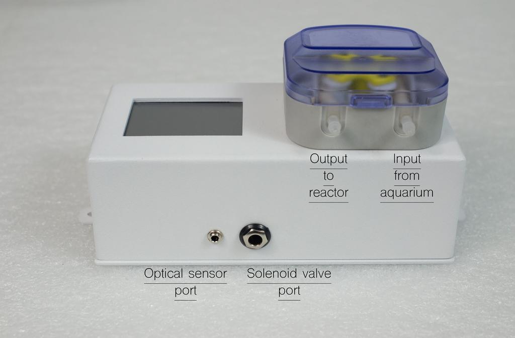
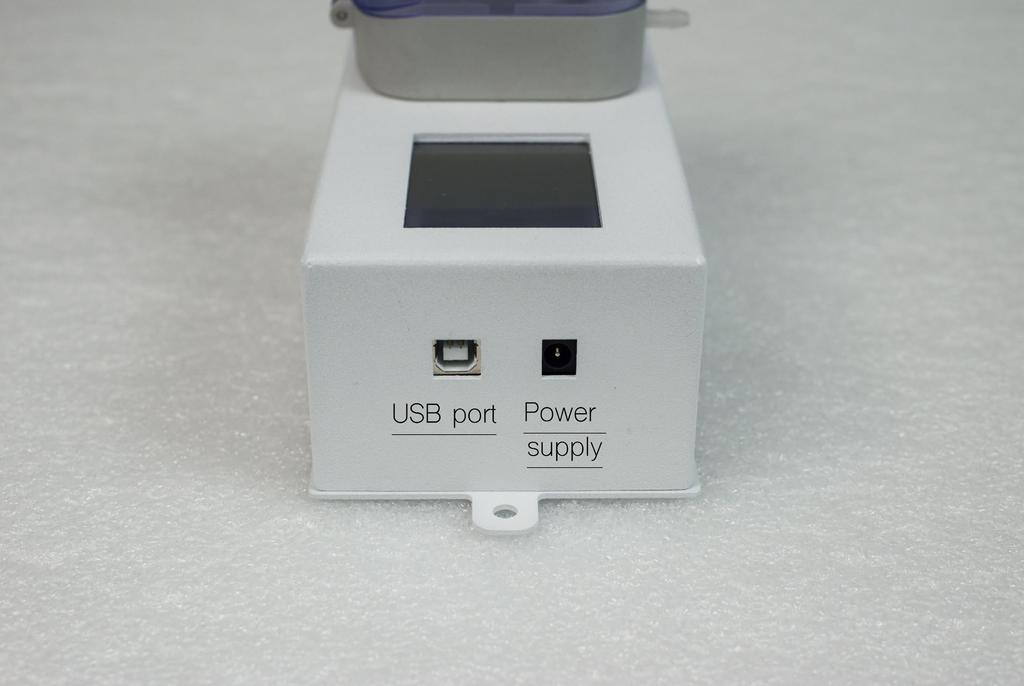
6 How Calcium Reactors Work It is very important to maintain the proper amounts of calcium and alkalinity in a reef tank. Both can be quickly depleted by growing organisms, and need to be supplemented in order to maintain levels equivalent to natural sea water. A calcium carbonate reactor is the easiest and most accurate method of maintaining calcium and alkalinity. A calcium reactor works by dissolving small amounts of solid calcium carbonate media into liquid form, which is then dosed back to the tank. The concentrated liquid that is added back to the tank contains the correct ratio of calcium to alkalinity, which is essential to maintain the proper balance of water chemistry. Unlike most additives or kalkwasser, a properly functioning calcium reactor should maintain the appropriate balance between calcium and alkalinity over the longterm. The reactor is filled with calcium carbonate media (such as reef sand, shells, ready to use media like ARM from CaribSea etc.) and saltwater. We recommend a grain size from 10mm upwards as this creates a better flow and will avoid partial compression of the granules at bottom of reactor. A small amount of carbon dioxide is added to the water inside the reactor, which lowers the ph to a range of At such a low ph, the calcium media begins to dissolve, thereby releasing the calcium and alkalinity ions so that they can be dosed back to the aquarium. This solution is very concentrated, so only a small amount of liquid, or effluent, needs to be dripped back to the aquarium. Over time, both the calcium media and carbon dioxide gas will become depleted. The rate of consumption will depend on your aquarium s calcium demand, but in most cases you can expect the reactor to work for several months without any major maintenance. It is important to periodically check the CO2 input rate (measured in bubbles per minute) and the effluent drip rate, to make sure that everything is flowing smoothly. Also, it is critical that you test your aquarium s calcium and alkalinity levels with a reliable test kit on a regular basis. Preparation for start-up Acceptable Range for Calcium and Alkalinity meq/l (7-11 dkh) alkalinity and ppm calcium Do not proceed if your results fall outside this range! 1. Remove covers from both reactor columns. 2. Flush the main reactor columns and fill it with calcium. 3. Flood the CO2 mixing column with water to remove the air totally, close the cover of the mixing column (with bioballs). Tighten the bolts to make a leak-proof closing. Tighten the opposite bolts alternately to distribute the closing load evenly. 4. Pour water to the column with calcium bed to the very top of the reaction column. 5. Carefully close the reaction column and again tighten the bolts alternately. 6. Connect the CalcFeeder PRO controller. Do not connect the solenoid valve at that stage. 7. Start the main pump (white, fastened to the reactor s base) water will start to circulate in the reactor s circuit. 8. Start the metering pump at about 2 liters/hour the pomp will add water to the reactor and remove the air residues present under the cover of the reactor s man column. Now your reactor is ready to connect the controller and the fixtures such as CO2 cylinder and solenoid valve. Connect the solenoid valve to the CO2 cylinder (equipped with a pressure gauge and precise CO2 outflow regulator) We recommend to set the cylinder pressure so that the CO2 feed at the regulator output is 2-4 bubbles per second. Important! Dosing pump will not start working till optical sensor will not read carbon dioxie in mixing chamber. You need to wait few minutes (if regulator output is set for 2-4 bubbles per second) for reaching proper CO2 level in mixing chamber. If during regular time sensor will not read CO2 and on screen controller inform about ERROR - simply restart it(disconnect for few seconds from power supply and connect again). Repeat procedure till sensor will read proper carbon dioxide level and dosing pump start working(optical sensor status will turn into GREEN). Page 6
7 After setting the correct gas pressure, connect the CO2 solenoid valve (supplied with the reactor) observing the correct gas flow direction from the cylinder to the reactor as indicated by a small arrow on the solenoid valve housing. Make sure the connections are tight, retighten the connectors if necessary but do not use an excessive force as this can damage them. Connect the solenoid valve to CO2 Input. Connect the hose from CalcFeeder PRO controller to Water Input. The hose supplying water to the metering pump should be fastened in a dedicated holder and placed below the water level at all times (this will prevent pumping the air to the reactor). Route the Water Output from the reactor back to the sump (Important! The hose end must be below the water level at all times) or to the DC-1 or DC-2 degassing column bottom connector on the column. Starting the reactor: After making correct connections you can start your reactor. Proceed as follows: 1. Make sure CO2 is connected and the valve is open (the solenoid valve should be disconnected from the controller and the controller should be disconnected from the power supply). 2. The main circulation pump should run and no air should be present in the reactor s column. 3. Connect the solenoid valve to the controller and plug in the optical sensor placed in the reactor s column. 4. Connect the power supply to the CalcFeeder controller. After the preliminary test, the device is ready for operation. As after the start there is no CO2 in the reactor s column, the indicator light on the optical sensor will start to flash red, and after a few seconds the solenoid valve will open and supply CO2 to the reactor s column. 5. After a few CO2 feed cycles, its level should be adequate which will be indicated by the optical sensor light on the LCD display (from yellow/red it will turn green). 6. During the first dozen or so hours of reactor operation the controller will feed CO2 and start the solenoid valve rather often until water in the reactor s column becomes sufficiently saturated with gas. Later the starts/ stops of the solenoid valve will be much less frequent and will depend only on the amount of water supplied by the reactor to the filtration system in your aquarium. 7. In the first days of reactor operation set the metering pump flow to ml/h. Page 7
8 Safety informations The reactor unit should not be run 24-7 on small tanks (due to the ph lowering effects of a calcium reactor). To obtain the best results run the unit for 8-10 hours per day. The reactor should start to run 4 hours after the lights have come on. This will enable the highest ph to be maintained within the aquarium. If the reactor is running at maximum capacity then to reduce the likelihood of carry over of excess CO2 into the tank run the outlet through a further cup of reactor media to degas the water before it returns to the tank. Use equipment only for its intended use. Do not install outdoors or near sources of extreme heat. Avoid exposure to UV. Install out of the reach of children - special attention should be given to ensure children cannot access the CO2. Check the reactor every 3 months, or at least when refilling. It is recommended to check the reactor output flow rate and ph on a weekly basis. Use media with a grain size of at least 8-10 mm, and preferably mm or larger. This ensures optimum flow behavior. Media contains CO2 insoluble compounds and over time these will collect as sludge on the bottom of the reactor and should be removed at regular cleaning intervals. Regularly check the circulation pump and impeller. To do this, drain the reactor and disconnect all cables. The pump motor can easily be removed from the impeller housing by twisting in an anti clockwise direction. Troubleshooting 1. The reactor gets the air in and there is too much CO2 in the system. Answer: make sure the pressure in cylinder is correct and the gas metering is not faster than 1-2 bubbles per second. If your pressure gauge does not allow a precise adjustment, we suggest that you buy a sufficiently accurate valve, as the reliable and correct operation of the whole system largely depends on this component. Make sure the optical sensor is correctly plugged to the controller. 2. The optical sensor does not indicate a correct CO2 level an error message appears on the controller display. Answer: make sure the pressure in cylinder is correct and the valve on the cylinder is not closed. Recheck the gas flow between the cylinder and the solenoid valve. Make sure the solenoid valve is plugged to the controller. Set the water flow at the pump according to the requirements of your aquarium. We suggest that you start from 500ml/h and increase slowly according to needs. Remember that before starting the reactor the water parameters such as Ca and kh should be adequately proportional relative to each other. The reactor is not for balancing the parameters, but for supplementing them in proportional amounts. 3. Circulation pump not running(no water circulation in the reactor). Answer: Air lock in reactor turn off circulation pump than release gas build up by loosening gas collection trap screw. Before turning pump on, completely refill reactor with water. Check the CO2 supply rate. Check impeller not jammed with media/sludge. 4. Circulation pump is too hot during operation: Answer: See above. 5. Circulation pump rattles: Answer: Remove the circulation pump motor. Clean any granular particles or debris. 6. Discharge from the reactor is too low. Answer: Check flow in and flow out for blockages - replace the hoses if necessary. Check dosing pump tubing against any damages. 7. No bubbles in the bubble counter: Answer: Check the CO2 bottle is not empty. Check supply hoses for leaks Page 8
UsER manual for Watersens ph -REDOX
 UsER manual for Watersens -REDOX Cl 8 1 2 6 3 3 7 7 4 4 4 4 Parts List 1 Redox Probe 1 x 2 PH Probe 1 x 5 Tube Weight 2 x 6 Connection Valve 1 x chlorine 3 Chlorine and Pumps 2 x 7 Dosing Valve 2 x 5 5
User's Manual. MixRite TF 10. Edition 05.08
 User's Manual MixRite TF 10 Edition 05.08 1 Tefen MixRite TF 10 fertilizer and chemicals Injector Congratulations on your purchase of one of Tefen s high quality products. To get the best results from
Installation Operation Maintenance. Bermad Level Control Valve with Modulating Horizontal Float Pilot valve One Way Flow IOM.
 Bermad Level Control Valve with Modulating Horizontal Float Pilot valve One Way Flow Model: FP 450-80 Installation Operation Maintenance PAGE 1 OF 5 1. Safety First BERMAD believes that the safety of personnel
Installation and Maintenance Manual. ECO Filtration Unit with 6-way-Top-Mount-Valve. Art. Nr
 Installation and Maintenance Manual ECO Filtration Unit with 6-way-Top-Mount-Valve Art. Nr. 300100 300101 300102 Important Details: - Using of this filtration unit for swimming pools and its guard band
Model: 43T. Bermad Pressure Relief Valve
 Model: 43T Bermad Pressure Relief Valve Installation Operation Maintenance Manual () Rev.C1_01.08.17 Page 1 of 10 Safety First BERMAD believes that the safety of personnel working with and around our equipment
256 Pneumatic Pressure Indicator
 256 Pneumatic Pressure Indicator 51425699 Copyright 2002 Slope Indicator Company. All Rights Reserved. This equipment should be installed, maintained, and operated by technically qualified personnel. Any
DRS4-RM Manual. Set Up Instructions for DRS4 Series Single Tank
 Set Up Instructions for DRS4 Series Single Tank Inspect the packaging of the equipment to confirm that nothing was damaged during shipping. (Figure 1) Remove the resin tank(s) and valve(s) from the packaging.
ABRASIVE REGULATOR II
 ABRASIVE REGULATOR II 13096 Abrasive Regulator II TABLE OF CONTENTS 1 Introduction... 1 2 Abrasive Regulator... 2 2.1 Regulator Installation... 2 Location... 2 Attaching the Regulator to the Machine...
Equipment Operating Procedure Glove Box
 Equipment Operating Procedure Glove Box Page 1 0.0 Changing the Compressed Gas Cylinder 1. Complete Compressed Gas Cylinder training from EHS website before manually exchanging gas cylinders. In order
LIBERTY and PATRIOT SAND FILTER SERIES INSTALLATION & OPERATION MANUAL. RX Clear Patriot Sand Filters
 LIBERTY and PATRIOT SAND FILTER SERIES INSTALLATION & OPERATION MANUAL RX Clear Patriot Sand Filters 8 Tank 12 Tank 16 Tank 22 Tank 24 Tank MLA-F91-PS08 MLA-F91-PS12 MLA- F91-PS16 MLA-F91-PS22 MLA-F91-P24
Swell UK. The UK's leading online aquatic retailer.
 Swell UK The UK's leading online aquatic retailer www.swelluk.com - Operation Manual ph - Computer With the purchase of this digital measuring and control equipment you have selected a top quality product.
User Manual: Ozone Swim 1000, 2000 and 3000 Series
 User Manual: Ozone Swim 1000, 2000 and 3000 Series P a g e 1 15 Important Safety Information This manual contains important information about the operation and safe use of this product. READ AND FOLLOW
ABRASIVE REGULATOR II
 ABRASIVE REGULATOR II 13096 Abrasive Regulator II TABLE OF CONTENTS Contact Information and Customer & Technical Service... 1 1 Introduction... 1 2 Abrasive Regulator... 1 Description:... 1 2.1 Regulator
Model: 720-UL INSTALLATION OPERATION MAINTENANCE. Bermad Pressure Reducing Valve IOM. Model: FP -720-UL Sizes: 2"-12" BERMAD. Application Engineering
 Bermad Pressure Reducing Valve Model: 720-UL INSTALLATION OPERATION MAINTENANCE Application Engineering BERMAD 1. Safety First BERMAD believes that the safety of personnel working with and around our equipment
FX134, FX1234, FX3030 Problem and Solutions
 FX134, FX1234, FX3030 Problem and Solutions Unit Will Not Power Up Turn the power switch on. The unit LCD will display revision program and filter life within 3 to 5 seconds after turning on unit. If this
product manual HM-4140, HM-4150, HM-4160 HM-4160A HM-4150 Humboldt FlexPanels
 12.09 product manual HM-4140, HM-4150, HM-4160 HM-4160A HM-4150 Humboldt FlexPanels Introduction: This manual covers the installation and operation of Humboldt FlexPanels for Triaxial and Permeability
Instructions for Use
 Select-380 T-Auto T-Auto Contents Page Instructions for Use Ref: 3.0 IFU 380 T-Auto Mar 18 2 Schematic layout of the doser 3 Quick-fit instructions 4 Description/Installation/Operation Pump tubes & Water
User s Guide. Vacuum Controller for liquid delivery systems
 Flow Control User s Guide Vacuum Controller for liquid delivery systems Precise Vacuum Control throughout the experiment Flow control Compatible with any perfusion system Ideal for Small Volume Delivery
Accu-Tab Systems 2000 P Series by Axiall Corporation
 Accu-Tab Systems 2000 P Series by Axiall Corporation Installation and Operating Instructions Models 2075 P 2150 P For NSF/ANSI-Standard 61 NSF STANDARD 61 applications use NSF/ANSI Standard 60 listed Axiall
Exercise 2-3. Flow Rate and Velocity EXERCISE OBJECTIVE C C C
 Exercise 2-3 EXERCISE OBJECTIVE C C C To describe the operation of a flow control valve; To establish the relationship between flow rate and velocity; To operate meter-in, meter-out, and bypass flow control
Visit:
 CORAL CLASSIC SPA START UP INSTRUCTIONS Remove the filter from the spa, see page 8 in your user manual. Place a hose in the filter box to fill the spa with water, see page 7 in your user manual. Remove
Product Sheet Spraymist Unit
 Product Sheet Spraymist Unit DESCRIPTION The Spraymist unit is perfectly adapted for use with differents liquids for applications as metalcutting, drilling, grinding, cooling or wetting processes and chain
WARNING: READ THE GENERAL INFORMATION MANUAL INCLUDED FOR OPERATING AND SAFETY PRECAUTIONS AND OTHER IMPORTANT INFORMATION.
 GSR500 Ram Assembly General Description The GSR500 single post lift / ram uses a 3-1/4 air powered cylinder, which is welded to a heavy gauge base. It is normally used to raise and lower a fluid handling
A4 Operation Manual. Fig.1-1 Controller Socket Diagram
 A4 Operation Manual Safety Instruction Please read this manual carefully, also with related manual for the machinery before use the controller. For installing and operating the controller properly and
OPERATING MANUAL LO-CROSS-FLOW CF M
 VA FILTRATION USA 110 Dodd Court American Canyon, CA 94503 Tel : (707) 552 2616 Fax :(707) 552 3871 Web : www.vafiltration.com OPERATING MANUAL LO-CROSS-FLOW CF8-2-200M January, 2017 TECHNICAL SPECIFICATIONS
MoveRoll Conveyor Operating and Maintenance Manual
 MoveRoll Conveyor Operating and Maintenance Manual 1. Read this first! This manual contains information for protection of personnel in the roll handling area from possible injury and/or equipment damage.
FAULT CODE TROUBLESHOOTING INDEX
 FAULT CODE TROUBLESHOOTING INDEX 1. Display indicates Change Filters 2. Display indicates Drip Tray Full Continuous Alarm will Sound 3. Display indicates Cold Fault 4. Display indicates Hot Fault 5. Display
Rejuvenation Instructions
 Rejuvenation Instructions #401 Air Systems UPR This NRI covers the following: Understanding the applications and operation of flow meters. Understand the application and operation of test pressure gauges.
Accu-Tab Systems 1000 Series by Axiall Corporation
 Accu-Tab Systems 1000 Series by Axiall Corporation Installation and Operating Instructions Model 1050 DANGER: DO NOT MIX CHEMICALS! The Accu-Tab chlorinator is designed for use with Axiall approved tablets
A4s Operation Manual
 A4s Operation Manual Safety Instruction Please read this manual carefully, also with related manual for the machinery before use the controller. For installing and operating the controller properly and
Light Commercial Reverse Osmosis System. EE-1000 Manual
 Light Commercial Reverse Osmosis System EE-1000 Manual Nimbus Water Systems 41840 McAlby Court, Suite A Murrieta, CA 92562 800-451-9343 Fax 951-894-2801 www.nimbuswater.com Nimbus Water Systems 1 EE-1000
TANK MANAGER FOR TWO TANKS OPERATING MANUAL. 10/31/11 C-More T6C L color touch panel
 TANK MANAGER FOR TWO TANKS OPERATING MANUAL 10/31/11 C-More T6C L color touch panel 1 TABLE OF CONTENTS GENERAL...3 INSTALLATION...4 STONE TEST PROCEDURE...7 OPERATIONAL SUMMARY...7 AUTO CARBONATION...10
Navigator 600 Silica analyzers
 ABB MEASUREMENT & ANALYTICS INFORMATION INF09/020 REV. B Navigator 600 Silica analyzers Troubleshooting Measurement made easy Navigator 600 silica analyzers 1 Introduction This publication details troubleshooting
accidents which arise due to non-observance of these instructions and the safety information herein.
 3 GALLON PANCAKE COMPRESSOR Model: 50959 CALIFORNIA PROPOSITION 65 WARNING: You can create dust when you cut, sand, drill or grind materials such as wood, paint, metal, concrete, cement, or other masonry.
INSTALLATION. and INSTRUCTION MANUAL. for QUALITY AIR BREATHING SYSTEMS. Model 50 Systems Outfitted with ABM-725 Monitor C O M P A N Y
 INSTALLATION and INSTRUCTION MANUAL for QUALITY AIR BREATHING SYSTEMS Model 50 Systems Outfitted with ABM-725 Monitor M A R T E C H S E R V I C E S C O M P A N Y OFFICE: (507) 843-4700 P.O. BOX 7079 Toll
Pool Information 2015
 Pool Information 2015 A regular maintenance program will help prevent problems with the pool and the pool water. There are many elements that can influence the clarity and purity of the water. To keep
SomnoSuite FAQ. Setup. Calibration 4. What are the calibration requirements for the SomnoSuite? Settings
 SomnoSuite FAQ V1.3 January 2015 Setup 1. How do I connect the SomnoSuite to my oxygen source? 2. Is there a way to speed up the downward movement of the pusher block when setting the empty position? 3.
Glove Box Installation Manual
 Glove Box Installation Manual 1998 by M. Braun Company File: GB-UNI-INS.DOC! Edition 08-00 by M. Boutin! Subject to be changed without notice Glovebox Installation Your Glove box has been fully assembled,
WW-720. Pressure Reducing Control Valve
 WW-720 Pressure Reducing Control Valve (Size Ranges: 2-4 and 6-14 ) Installation Operation & Maintenance Page 1 of 6 1. DESCRIPTION The Model 720 Pressure Reducing is an automatic control valve (powered
Installation, Operation, and Maintenance Manual
 Installation, Operation, and Maintenance Manual Welker The information in this manual has been carefully checked for accuracy and is intended to be used as a guide for the installation, operation, and
Instructions for SILEX 1C Mixed bed cartridge filter
 D01B-30A-UK1 January 2017 Instructions for SILEX 1C Mixed bed cartridge filter With conductivity sensor Gravity flow or pressure installation SILHORKO-EUROWATER A/S Phone +45 86 57 12 22 DK-8660 Skanderborg
2. Determine how the mass transfer rate is affected by gas flow rate and liquid flow rate.
 Goals for Gas Absorption Experiment: 1. Evaluate the performance of packed gas-liquid absorption tower. 2. Determine how the mass transfer rate is affected by gas flow rate and liquid flow rate. 3. Consider
WW-720. Pressure Reducing Control Valve
 WW-720 Pressure Reducing Control Valve (Size Ranges: 2-4 and 6-14 ) Installation Operation & Maintenance Page 1 of 6 1. DESCRIPTION The Model 720 Pressure Reducing is an automatic control valve (powered
Instructions for Assembly, Installation, and Operation of the Gas Addition Kit Accessory with the CEM Discover Systems
 Corporation Issued: 5/09 P/N: 600104 Rev. 2 Instructions for Assembly, Installation, and Operation of the Gas Addition Kit Accessory with the CEM Discover Systems The Gas Addition Accessory permits the
Installation Instructions
 Page 5750-S-1 Installation Instructions General These mounting instructions for Circular INCINO- PAK Burners are in addition to the specific instructions offered for other Maxon component items: Shut-Off
97C COMPRESSOR KIT 12V PART NO C COMPRESSOR KIT 24V PART NO C COMPRESSOR KIT PART NO
 97C COMPRESSOR KIT 12V PART NO. 00097 97C COMPRESSOR KIT 24V PART NO. 02497 98C COMPRESSOR KIT PART NO. 00098 97C 98C IMPORTANT: It is essential that you and any other operator of this product read and
Table of Contents. Sensor Calibration and Troubleshooting CDS4000 CO 2. Introduction 1. Handling Information. Calibration 2.
 FANs 216, 1628.3 Technical Bulletin CDS4000 Issue Date 0797 CDS4000 CO 2 Sensor Calibration and Troubleshooting Table of Contents Introduction 1 Handling Information 1 Calibration 2 Preparation 2 Cautions
ABRASIVE SYSTEM ABRASIVE REGULATOR II 800# BULK ABRASIVE DELIVERY POT Abrasive Regulator II and 800# Pot Manual
 ABRASIVE SYSTEM ABRASIVE REGULATOR II 800# BULK ABRASIVE DELIVERY POT TABLE OF CONTENTS Contact Information and Customer & Technical Service... 1 1 Introduction... 1 2 Abrasive Regulator... 1 Description:...
MODEL 1329 Tank Gauge
 SERVICE INSTRUCTIONS FOR PETRO-METER 1329 GAUGE SERVICE INSTRUCTIONS MODEL 1329 Tank Gauge www.petro-meter.com Petro-Meter 1329 series Service Instructions HOW TO DETERMINE IF A PETRO-METER IS IN GOOD
RARS5000 AIR BODY SAW OWNER S OPERATING MANUAL
 RARS5000 AIR BODY SAW OWNER S OPERATING MANUAL DESCRIPTION 1. No mar 2. No mar tip 3. Housing grip 4. Trigger 5. Air inlet 6. Air inlet plug 7. Plastic board Important! It is essential that you read the
SPECIFICATIONS APCEPH1
 APCEPH1 ph CONTROLLER SPECIFICATIONS APCEPH1 Input voltage 120 Volts AC Maximum amperage 14.5 amps @ 120 VAC ph Accuracy +/- 0.2 ph ph Control range Adjustable 4.5 8.5 ph Weight < 1 lbs Dimensions 3" x
!!!! SERVICE MANUAL PRESSURE POT 2 GALLON. Service Manual: LT Washington St 931 Progress Ave., #7
 EXEL North America, Inc. EXEL Industrial Canada, Inc. 1310 Washington St 931 Progress Ave., #7 West Chicago, IL 60185 Scarborough ONT, M1G 3V5 Ph : (800) 573 5554 Ph : (800) 450 0655 Fx : (800) 664 1511
Farm Chlor Chlorinator Instruction Manual
 Farm Chlor Chlorinator Instruction Manual 1 2 GEA FIL FARM CHLOR CHLORINATOR INSTRUCTION MANUAL Content Welcome to improved water quality 3 Key Features and Benefits Chlorine Use What s included? 4 Installation
SUMMITTM 400 & 600. Natural Gas Barbecues. Step-By-Step Guide
 SUMMITTM 400 & 600 Natural Gas Barbecues Step-By-Step Guide W E B E R W E B E R W E B E R W E B E R Summit 400 NG Summit 600 NG CANADIAN GAS ASSOCIATION R A P P R O V E D WARNING: Follow all leak check
SPIROVENT VACUUM DEGASSERS
 SPIROVENT VACUUM DEGASSERS S P I R O V E N T A I R S U P E R I O R FLUID AND GAS There are always a certain amount of gasses in a fluid, dependent on pressure and temperature. The British physicist William
Unit 24: Applications of Pneumatics and Hydraulics
 Unit 24: Applications of Pneumatics and Hydraulics Unit code: J/601/1496 QCF level: 4 Credit value: 15 OUTCOME 2 TUTORIAL 9 ACCUMULATORS The material needed for outcome 2 is very extensive so there are
I T T Pressure Reducing Valve WARNING INSTALLATION, OPERATION, AND MAINTENANCE MANUAL
 INSTALLATION, OPERATION, AND MAINTENANCE MANUAL I-867-4T 867-4T Pressure Reducing Valve HANG THESE INSTRUCTIONS ON THE INSTALLED VALVE FOR FUTURE REFERENCE WARNING Read and understand all instructions
IMPORTANT PLEASE READ BEFORE COMMENCING INSTALLATION
 IMPORTANT PLEASE READ BEFORE COMMENCING INSTALLATION This Fitting Guide is designed to assist in the Installation of your Reverse Osmosis System. Some of the parts that are supplied with each system may
Mini-Pro CO2 Sensor User s Manual - ANALOG MODEL -
 Mini-Pro CO2 Sensor User s Manual - ANALOG MODEL - Table of Contents 1. Introduction 3 2. Instrument Setup 4 2.1 Instrument Checklist 4 2.2 Optional Accessories 4 2.3 Gas Concentration Ranges Available
400H HARDMOUNT AIR COMPRESSOR KIT PART NO H HARDMOUNT AIR COMPRESSOR KIT PART NO
 400H HARDMOUNT AIR COMPRESSOR KIT PART NO. 40042 450H HARDMOUNT AIR COMPRESSOR KIT PART NO. 45042 400H 450H IMPORTANT: It is essential that you and any other operator of this product read and understand
Salt Sanitizing System for Above Ground Pools Up to 25,000 Gallons
 Salt Sanitizing System for Above Ground Pools Up to 25,000 Gallons OWNER'S MANUAL Salt Sanitizing System for Above Ground Pools OWNER'S MANUAL Thank you for purchasing our product. Before installation
Gas Mixing System. Operator s Manual. This manual is also available online
 Brownie s M A R I N E G R O U P Tri-Ox MAKER TM Gas Mixing System Operator s Manual This manual is also available online 940 NW First Street, Fort Lauderdale, FL 33311 USA Ph 954-462-5570 Fx 954-462-6115
HGC-200 Hydro Gas Chlorinator
 HGC-200 Hydro Gas Chlorinator ProMinent Fluid Controls Pty Ltd Head Office: Unit 4, 4 Narabang Way BELROSE NSW 2085 AUSTRALIA (PO Box 85, BELROSE WEST NSW 2085) Phone: (02) 9450 0995 Fax: (02) 9450 0996
PERFORM Operating Document
 PERFORM Operating Document Use and Maintenance of CO 2 Incubator PC-POD-CA-007-v03 Revision History Version Reason for Revision Date 01 New POD 30-Sep-13 02 Minor revisions for section 2.3, 3.1, 4.3. 14-April-16
BSS 2 Bottle Sampling System. Instruction manual Version 1.8
 BSS 2 Bottle Sampling System Instruction manual Version 1.8 Serial-No.:... Version-/Rev.-Date : 12.06.2012 Contents 1. General... 3 2. Safety Instructions... 4 3. Extent of Delivery... 5 4. Switch Panel...
Operating Instructions Model and Hydrostatic Test Pump
 Operating Instructions Model 29200 and 2920 Hydrostatic Test Pump Dimension Weight Pump Pressure for 29200 Pump Pressure for 2920 Gauge for 29200 Gauge for 2920 Inlet Connection Outlet Connection Hose
NEWS: 20% discount on service agreements signed before 1st March 2010
 Swimming Pool Maintenance Routine and charges Regular maintenance and consistent pool care is the best way to ensure a safe and healthy swimming environment. Although every pool is unique and has its own
Hurlcon KX Siesta Above Ground Salt Water Chlorinator by AstralPool Australia
 Hurlcon KX Siesta Above Ground Salt Water Chlorinator by AstralPool Australia OPERATING INSTRUCTIONS AstralPool Australia Pty. Limited. A.B.N. 97 007 284 504 Melbourne: Ph: (03) 8796 8600 Fax: (03) 8796
Installation of Your SprayMaster System
 Installation of Your SprayMaster System 1. At the installation site, remove all equipment from the corrugated box and the polyethylene drum and replace the drum lid. Check the picture to identify each
CAST IRON VALVES FLOAT VALVE
 CAST IRON VALVES FLOAT VALVE NETAFIM CAST IRON VALVES FLOAT VALVE INLINE 25-400MM ANGLE 50-100MM SPECIFICATIONS Manufactured to ISO 9001 Available Valve sizes INLINE Flanged 50mm to 600mm & Threaded 19mm
ChlorMaker DO OPERATING INSTRUCTIONS DO - DRAPE OVER
 ChlorMaker DO TM DO - DRAPE OVER OPERATING INSTRUCTIONS ControlOMatic, Inc. 12659 Arbor Lane, Grass Valley, CA 95949 www.controlomatic.com Support@ControlOMatic.com 530-205-4520 Manual Version: 1/1/13
SALT WATER CHLORINATORS INSTALLATION INSTRUCTIONS
 SALT WATER CHLORINATORS INSTALLATION INSTRUCTIONS An introduction to salt water chlorination. Salt water chlorination is the healthy alternative to chlorinating your swimming pool, the natural way. Very
OWNER S TECHNICAL MANUAL
 EL SERIES OWNER S TECHNICAL MANUAL DP7002 1 Air Operated Diaphragm Pump Description The DP7002 1 air operated diaphragm pump is the ideal device for the pumping, transfer and dispensing of chemical liquids,
V10K GAS FEED SYSTEM WALLACE & TIERNAN PRODUCTS
 V10K GAS FEED SYSTEM WALLACE & TIERNAN PRODUCTS V10K SYSTEM: PROVEN TECHNOLOGY WORLDWIDE IN USE Since Charles F. Wallace and Martin F. Tiernan discovered the first chlorine gas feed system in 1913 the
icon i150 / i350 Installation / Operation Manual
 i150 Concentrator i350 Concentrator icon i150 / i350 Installation / Operation Manual www.iconcentrator.com What You Will Need to Install Your icon In order to install your icon you will have to consider
Copyright, 2005 GPM Hydraulic Consulting, Inc.
 Troubleshooting and Preventive Maintenance of Hydraulic Systems Learning to Read the Signs of Future System Failures Instructed by: Al Smiley & Alan Dellinger Copyright, 2005 GPM Hydraulic Consulting,
User Manual. MagnaMaster and ChloroMaster Electrolytic Chlorinator.
 User Manual MagnaMaster and ChloroMaster Electrolytic Chlorinator www.directpoolsupplies.com.au Contents Introducing the MagnaMaster and ChloroMaster 1 How it Works 1 Installation Guide 1 Initial Pool
User s Guide. CO2 & O2 Controller for miniature incubators
 CO2 O2 Control User s Guide CO2 & O2 Controller for miniature incubators Precise CO2 & O2 Control throughout the experiment Media ph control Compatible with any perfusion system Miniature incubators for
Auto EVAP Quick Start Guide
 Auto EVAP Quick Start Guide Pg. 13 Note: Never directly hit or drop the leak detector on the CO2 sensor tip, this will cause the sensor to become damaged! Do not get Leak Seeker Solution directly on the
Operating Procedure TITON SUBSEA BOLT TENSIONER
 Operating Procedure TITON SUBSEA BOLT TENSIONER B & A Hydraulics Ltd Block 1, Units 1 & 2 Souter Head Industrial Centre Souter Head Road Altens Aberdeen Phone: 01224 898955 Fax: 01224 898787 E-Mail: TITON@bahyd.co.uk
UltRo Dual Flow Reverse Osmosis Water System
 UltRo Dual Flow Reverse Osmosis Water System Congratulations on this great investment to your health. **IMPORTANT NOTE BEFORE YOU BEGIN** We recommend you call your local friendly plumber to ensure proper
OPERATION MANUAL NTF-60 Plus
 OPERATION MANUAL NTF-60 Plus Nitrogen Tire Filling Valve Stem Caps (Qty=200) Order P/N 436075 RTI Technologies, Inc 10 Innovation Drive York, PA 17402 800-468-2321 www.rtitech.com 035-81264-00 (Rev A)
TEST BENCH SAFETY VALVES ¼ - 5 DN10 DN125
 TEST BENCH SAFETY VALVES ¼ - 5 DN10 DN125 Model: VC-40-VYC Table of contents 1. - Installing the test bench 1.1.1- Connecting the compressed air / nitrogen source 1.1.2- Maximum test pressure according
QUIK-jet Micro-Injection System
 QUIK-jet Micro-Injection System Training Manual Revision Date: 11/12/07 Table of Contents Subject Headings Pages Introduction 3 Parts of the QUIK-jet Kit 4 QUIK-jet Assembly and Setup 5-6 3 Easy Steps
ACV-10 Automatic Control Valve
 ACV-10 Automatic Control Valve Installation, Operation & Maintenance General: The Archer Instruments ACV-10 is a precision automatic feed rate control valve for use in vacuum systems feeding Chlorine,
User Instruction Manual
 User Instruction Manual 4500 psi Air Compressor Ver 2, 1.18 Contents Parts Included...3 Assembly Instructions...3-5 Operation Instructions...6-7 Oil Change Intervals...8 Air Filter Replacement...9 Setting
100C Air Compressor Kit
 10010 100C Air Compressor (standard mounting bracket, CE Spec) 10014 100C Air Compressor (no leader hose or check valve, CE Spec) 10016 100C Air Compressor (with Omega Bracket, CE Spec) IMPORTANT: It is
Dolphin Hybrid RS1 - Suction Pool Cleaner. Operating Instructions
 Dolphin Hybrid RS1 - Suction Pool Cleaner Operating Instructions by 8151171 Dolphin_Hybrid_cover.indd 1 5/8/1 9:18 AM Dolphin_Hybrid_cover.indd 5/8/1 9:18 AM Contents The Dolphin Hybrid RS1 Suction Cleaner...
LNG Regulator Test Kit
 OVERVIEW Chart provides a LNG Economizer/Regulator Test Kit to help save money and time by allowing a technician to more accurately and easily diagnose the operability of the pressure control regulator/economizer
Catalina Spa-kle Installation and User Guide
 Catalina Spa-kle Installation and User Guide Computer controlled automatic bromine generator for spas, hot tubs and swimspas. 1 TABLE OF CONTENTS 1. Safety Instructions and Installer Precautions 2. Installation
PACKSETTER HAND PUMP
 PACKSETTER HAND PUMP 1 CONTENTS Introduction...3 1. Product Description 3 2. Design Criteria.. 3 3. Risk Assessment Team.. 3 4. Objectives... 4 5. Hazard Classification...4+5 Risk matrix..6 FACTOR/INDEX
/ Air Line Kit AL - M1202. / OPERATION MANUAL P1 - P9 / English P11 - P19 OM-K0651
 / Air Line Kit AL - M1202 / OPERATION MANUAL P1 - P9 / English P11 - P19 OM-K0651 002 1 Thank you for purchasing the Air Line Kit " AL - M1202 ". This Air Line Kit is designed to adjust the air supply
PURITY INSTALLATION INSTRUCTIONS MODEL P40
 Sunshine Pool Products, LLC Manufacturer of Quality Pool & Spa Products 902 West 2010 South, Syracuse, Utah 84075 Voice: 801-825-4523 Website: www.sunshinepool.com Email: info@sunshinepool.com PURITY INSTALLATION
Pegas 4000 MF Gas Mixer InstructionManual Columbus Instruments
 Pegas 4000 MF Gas Mixer InstructionManual Contents I Table of Contents Foreword Part I Introduction 1 2 1 System overview... 2 2 Specifications... 3 Part II Installation 4 1 Rear panel connections...
Hot Compressed Air Lance Operation Manual. LAB Manufacturing 9483 Reading Road Cincinnati, OH (800)
") Hot Compressed Air Lance Operation Manual www.heatlances.com LAB Manufacturing 9483 Reading Road Cincinnati, OH 45215 (800) 776-5830 PARTS CHECK LIST NOTE: Check all fittings & connections prior to operation.
Hot Compressed Air Lance Operation Manual www.heatlances.com LAB Manufacturing 9483 Reading Road Cincinnati, OH 45215 (800) 776-5830 PARTS CHECK LIST NOTE: Check all fittings & connections prior to operation.
SpectraPure PUMPED RO SYSTEMS (PSP) User s Manual for PSP-1500 Systems
 User s Manual for PSP-1500 Systems") SpectraPure PUMPED RO SYSTEMS (PSP) User s Manual for PSP-1500 Systems 2 3 PSP-1500 SYSTEM DESCRIPTION Reverse Osmosis RO Reverse Osmosis utilizes the unique properties of a semi-permeable membrane to
SpectraPure PUMPED RO SYSTEMS (PSP) User s Manual for PSP-1500 Systems 2 3 PSP-1500 SYSTEM DESCRIPTION Reverse Osmosis RO Reverse Osmosis utilizes the unique properties of a semi-permeable membrane to
INSTALLATION INSTRUCTIONS
 INSTALLATION INSTRUCTIONS HIGH PRESSURE PUMP To minimize vibration, it is best to build brackets on the motor itself, similar to alternator brackets. Use cardboard to construct a pattern first before making
Duplex Commercial Softeners
 Duplex Commercial Softeners Installation, Operation & Maintenance Guide Manual 003.1 Contents Page 1. Unpacking Instructions 3 2. Installation 4 Pre-installation checks Fitting the bottom distribution
GEN-1e CO2 Generator OVERVIEW INSTALLATION PROPANE GENERATORS ONLY NATURAL GAS GENERATORS ONLY
 GEN-1e CO2 Generator Custom Automated Products offers economical and safe carbon dioxide generators. They produce CO2 by burning either propane or natural gas. We have designed our CO2 generator to allow
OEM Manual. MODEL ½ Digit DRUM SCALE
 OEM Manual MODEL 4020-3 ½ Digit DRUM SCALE Scaletron Industries, Ltd. Bedminster Industrial Park 53 Apple Tree Lane P.O. Box 365 Plumsteadville, PA 18949 USA Toll Free: 1-800-257-5911 (USA & Canada) Phone: