UNITED STATES ARMY JUMPMASTER SCHOOL
|
|
|
- Junior Garrett
- 6 years ago
- Views:
Transcription

1 UNITED STATES ARMY JUMPMASTER SCHOOL STUDENT STUDY GUIDE January 2017 Fort Benning, Georgia Headquarters & Headquarters Company, 1 ST Battalion, 507 TH Parachute Infantry Regiment 1
2 THIS PAGE INTENTIONALLY LEFT BLANK. 2
3 TABLE OF CONTENTS T-11 PERSONNEL PARACHUTES TC Chapter 2 - Proper nomenclatures, rated capacities, tensile strengths, materials and dimensions of the T-11 main parachute and the T-11 reserve parachute system. Pages 5-17 SUSTAINED AIRBORNE TRAINING TC Chapters 3 & 8 Pages SERJT/E & Mock door training INDIVIDUAL EQUIPMENT CONTAINERS TC Chapters 2 & 12 - Proper nomenclature, characteristics, correct rigging, attaching and lowering procedures for the Modular Airborne Weapons Case and MOLLE Ruck Sack with Harness Single Point Release, the assembly of the Advanced Combat Helmet. Pages A SERIES CONTAINERS TC Chapter 14 Pages Proper nomenclature, characteristics, proper rigging procedures and rigging of the A- 21 cargo bag and A-7A cargo sling. DUTIES AND RESPONSIBILITIES OF THE JUMPMASTER AND SAFETY TC Chapters Prerequisites required to perform duties as a Jumpmaster or Safety Pages Duties and Responsibilities from the time of notification through completion of the Airborne Operation. ARMY AIRCRAFT TC Chapter 17 Pages Characteristics, capabilities, safety considerations and jump procedures for the UH- 60A Blackhawk and the CH-47 Chinook. AIR FORCE AIRCRAFT TC Chapter 16 - Characteristics, seating arrangements and in-flight rigging procedures for the C-130 Hercules and C-17 Globe-master Aircraft. Pages DUTIES AND RESPONSIBILITIES OF THE DZSO AND THE DZSTL TC Chapters 7 & Prerequisites to perform duties as DZSO/ DZSTL Specific duties and responsibilities, personnel and support requirements. Drop zone surveys, tactical assessment of a drop zone and how to score Air Force drops. Pages CARP DROP ZONES TC Chapters and AFI Pages Determine the minimum size requirements for a CARP drop zone, location of the control center and how to temporarily cease an airborne operation. U.S. ARMY JUMPMASTER SCHOOL DEFICIENCY NOTES - Grading procedures and deficiency list for JMPI testing. Pages PRACTICAL WORK IN THE AIRCRAFT (PWAC) TC Chapters 5, 10 & 16 - Proper sequence of jump commands and time warnings with their appropriate hand and arm signals. Pages Door procedures and door bundle ejection procedures. 3
4 T-11 HOLLYWOOD JMPI SEQUENCE TALK THROUGH - TC Chapter 9 Pages T-11 COMBAT JMPI SEQUENCE TALK THROUGH WITH THE MODULAR AIRBORNE WEAPONS CASE Pages TC Chapter 9 T- 11 NOMENCLATURE HANDOUT T-11 COMBAT JMPI SEQUENCE TALK THROUGH WITH ALICE PACK AND MODULAR AIRBORNE WEAPONS CASE - TC Chapter 9 Pages Pages LEGACY SYSTEM INFORMATION M1950 WEAPONS CASE TC Chapters 2 & 12 Page 151 T-11 COMBAT EQUIPMENT JMPI SEQUENCE TALK THROUGH WITH THE MOLLE RUCK SACK AND M1950 WEAPONS CASE - TC Chapter 9 T-11 COMBAT EQUIPMENT JMPI SEQUENCE TALK THROUGH WITH THE ALICE PACK AND M1950 WEAPONS CASE - TC Chapter 9 Pages Pages
5 T-11 MAIN PARACHUTE T-11 PERSONNEL PARACHUTES TC Chapter 2 The T-11 series parachute is used during static line airborne operations. The T-11 series is a non-steerable canopy. WEIGHT o Approx. 38 lbs. DIAMETER o Nominal: 28.6 feet o Modified Cruciform Planform in design SAFE DROP SPEEDS o 150 knots Maximum o 50 knots Minimum AVG. DEPLOYMENT TIME o 6.5 seconds RATE OF DECENT o Approximately 18.5 feet per second with a suspended weight of 400 lbs. The main parachute consists of ten major components: 1) *Universal static line modified 2) Deployment bag 3) Drogue parachute 4) Bridle assembly 5) Deployment sleeve 6) Canopy assembly 7) Slider 8) *Riser assembly 9) *Harness assembly 10) *Pack tray Asterisk denotes only items seen or touched while performing JMPI on a properly rigged jumper. UNIVERSAL STATIC LINE MODIFIED UNIVERSAL STATIC LINE SNAP HOOK The universal static line snap hook is the point of attachment for the universal static line modified to the aircraft s anchor line cable. It consists of a dual locking spring opening gate with a Rivet pin located approximately center mass. DIMENSIONS o Approx. 6 inches in length and approx. 2 inches wide MATERIAL o Type 4140 steel RATED CAPCITY o 1,750 lbs. UNIVERSAL STATIC LINE MODIFIED LENGTH o Approx. 15 feet MATERIAL o ¾ inch, tube edge, type 6.6 nylon webbing, yellow in color 5
6 TENSILE STRENGTH o 4,000 lbs. MAIN CURVED PIN The main curved pin is located approximately 12 feet from the universal static line snap hook. LENGTH o Approx. 1.3 inches MATERIAL o Stainless steel MAIN CURVED PIN ATTACHING LOOP The main curved pin attaching loop secures the main curved pin to the universal static line modified. MATERIAL o 3/8 inch wide Type I preshrunk nylon webbing. It may be green or white in color. TENSILE STRENGTH o 200 lbs. MAIN CURVED PIN COVER The main curved pin cover protects the main curved pin and main curved pin attaching loop. LENGTH o Approx. 6 inches MATERIAL o Cotton duck material STATIC LINE SLEEVE The static line sleeve prevents nylon-to-nylon contact between the universal static line modified and the pack tray. LENGTH o Approx. 27 inches MATERIAL o Cotton duck material RISER ASSEMBLY RISER ASSEMBLY When attached to the canopy, the riser assemblies provide four individual risers. RISERS LENGTH o Approx. 28 inches MATERIAL o Type VII nylon webbing TENSILE STRENGTH o 5500 lbs. SLIP ASSIST LOOP The slip assist loops are formed into the risers and sewn with reinforced stitching. They provide the jumper a means of securing a hand hold when executing slips. MATERIAL o Type VII nylon webbing 6
7 SLIP ASSIST TAB There are 3 slip assist tabs sewn to the front of each riser. They aid the jumper in executing slips. MATERIAL o Type XVII nylon webbing ARMY PARACHUTE LOG RECORD STOW POCKET The Army parachute log record stow pocket is sewn to the rear risers. It is utilized to store the DA Form 3912, Army Parachute Log Record. MALE FITTING CANOPY RELEASE ASSEMBLY MATERIAL o Cadmium plated forged steel alloy RATED CAPACITY o 2500 lbs. HARNESS ASSEMBLY HARNESS ASSEMBLY The harness assembly consists of a right and left upper main lift web assemblies and the lower saddle assembly. MATERIAL o Primarily constructed of type VII nylon webbing TENSILE STRENGTH o 5500 lbs. The harness assembly consists of the following items: 1) Canopy release assembly 2) D Rings 3) Main lift web 4) Tuck pocket 5) Chest strap 6) Chest strap friction adapter 7) Webbing retainer 8) Equipment ring 9) Ejector snap 10) L shaped ejector snap pad 11) Triangle link 12) Saddle 13) Leg straps 14) Quick fit V ring 15) Diagonal back strap 16) Sizing channels 17) Diagonal back strap pad 18) Back strap adjuster 19) Horizontal back strap There are nine points of adjustment on the harness assembly. They are: 1. Chest strap 2. Main lift web (2) 3. Leg strap (2) 4. Sizing channel (2) 5. Horizontal back strap (2) 7
8 FEMALE FITTING CANOPY RELEASE ASSEMBLY The heel of the male fitting canopy release assembly sits in the groove of the female fitting canopy release assembly. MATERIAL o Cadmium plated forged steel alloy RATED CAPACITY o 2500 lbs. LATCH The latch is utilized to secure the male fitting canopy release assembly to the female fitting canopy release assembly. CABLE LOOP The cable loop is approximately 2 inches in diameter. When pulled the cable loop disengages the latch, which separates the male fitting canopy release assembly from the female fitting canopy release assembly. This allows the jumper to recover from the drag. MATERIAL o Flexible stainless steel aircraft cable RATED CAPACITY o 920 lbs. SAFETY CLIP The safety clip secures the cable loop inside the canopy release assembly and prevents foreign material from entering the canopy release assembly. CANOPY RELEASE ASSEMBLY When completely assembled the rated capacity is 5000 lbs. D RINGS The D rings serve as points of attachment for the reserve parachute. MATERIAL o Cadmium plated forged steel alloy RATED CAPACITY o 5000 lbs. MAIN LIFT WEB The main lift web is adjustable and serves as 2 points of adjustment on the harness. The main lift web consists of the main lift web tuck tab assembly, the main lift web adjustment strap and the main lift web adjuster. LENGTH o Approximately 25 inches MATERIAL o Type VII nylon webbing and Type VIII nylon webbing TENSILE STRENGTH o 6000 lbs. MAIN LIFT WEB TUCK TAB ASSEMBLY The main lift web tuck tab assembly consists of a snap fastener and tuck tab. MAIN LIFT WEB ADJUSTMENT STRAP MATERIAL o 1 ply of Type VII nylon webbing and 1 ply Type VIII nylon webbing 8
9 MAIN LIFT WEB ADJUSTER MATERIAL o Cadmium plated forged steel alloy RATED CAPACITY o 2500 lbs. TUCK POCKET The main lift web is adjusted to 2 of the 3 sizes by inserting the tuck tab into the tuck pocket. CHEST STRAP The chest strap is sewn to the left main lift web. It serves as another point of adjustment on the parachute harness. There is a tabbed portion formed at the end of the chest strap. LENGTH o Approx. 23 inches MATERIAL o Type VII nylon webbing TENSILE STRENGTH o 5500 lbs. CHEST STRAP FRICTION ADAPTER The chest strap is secured to the chest strap friction adapter located on the right main lift web. LENGTH o Approx. 2 inches MATERIAL o Cadmium plated forged steel alloy RATED CAPACITY o 500 lbs. WEBBING RETAINER There are a total of 6 webbing retainers on the parachute harness. They can be replaced by a retainer band if they are not present or serviceable. MATERIAL o Type I elastic webbing EQUIPMENT RING The equipment rings are located just below the chest strap on the main lift web. They are used to secure items of combat equipment. MATERIAL o Cadmium plated forged steel alloy RATED CAPACITY o 2500 lbs. EJECTOR SNAP The ejector snaps for the leg straps are located on the main lift web below the main lift web adjusters. MATERIAL o Cadmium plated forged steel alloy RATED CAPACITY o 2500 lbs. The ejector snap consists of three sub components, they are: 1) ACTIVATING LEVER 2) BALL DETENT 3) OPENING GATE 9
10 L SHAPED EJECTOR SNAP PAD Located just below each ejector snap is the L shaped ejector snap pad. This is an added comfort feature and does not have to be present for the parachute harness to be serviceable. MATERIAL o Nylon duck cloth filled with ¼ inch thick cellular urethane foam TRIANGLE LINK The triangle links are located just below the leg strap ejector snaps. They serve as points of attachment for the ejector snap on the hook pile tape lower line. MATERIAL o Cadmium plated forged steel alloy RATED CAPACITY o 500 lbs. SADDLE Continuation of the main lift web and routed under the jumpers buttocks. MATERIAL o Type VII nylon webbing TENSILE STRENGTH o 5500 lbs. LEG STRAPS The leg straps are sewn midway through the saddle. They serve as 2 more points of adjustment on the parachute harness. LENGTH o Approx. 28 inches MATERIAL o Type VII nylon webbing TENSILE STRENGTH o 5500 lbs. QUICK FIT V-RING One quick fit V-ring is located at the end of each leg strap. They are attached to the appropriate ejector snap. MATERIAL o Cadmium plated forged steel alloy RATED CAPACITY o 2500 lbs. DIAGONAL BACK STRAP The diagonal back straps form an X across the jumpers back. They can be sized in five sizes and serve as 2 points of adjustment on the parachute harness. LENGTH o Approx. 20 inches MATERIAL o Two plies of Type VII nylon webbing TENSILE STRENGTH o 5500 lbs. 10
11 SIZING CHANNELS The sizing channels are numbered 1-5. There is no set size for any given jumper, however, when properly sized the canopy release assemblies should be located in the hollows of the jumper s shoulders just below the collar bones. DIAGONAL BACK STRAP PAD The diagonal back strap pad is an added comfort feature and does not have to be present for the parachute harness to be serviceable. DIMENSIONS o Approx. 12 ¼ inches at the longest point and approx. 3 ½ inches at the widest point. MATERIAL o Nylon duck cloth filled with ¼ inch thick cellular urethane foam BACK STRAP ADJUSTERS The back strap adjusters are located at the end of each diagonal back strap. MATERIAL o Cadmium plated forged steel alloy RATED CAPACITY o 2500 lbs. HORIZONTAL BACK STRAP The horizontal back strap is routed through the lower portion of the back strap adjuster, through the main lift web, across the small of the jumpers back, through the opposite main lift web and into the opposite back strap adjuster. It serves as 2 more points of adjustment on the parachute harness. LENGTH o Approx. 105 inches MATERIAL o Type VII nylon webbing TENSILE STRENGTH o 5500 lbs. PACK TRAY ASSEMBLY PACK TRAY ASSEMBLY DIMENSIONS o Approx. 20 inches long by 16 inches wide by 14 inches deep MATERIAL o Nylon duck cloth weighing approximately 7.25 ounces per square yard. The pack tray assembly consists of the following items: 1) Diagonal back strap retainer 2) Diagonal back strap keeper 3) Directional snap fastener 4) Horizontal back strap retainer 5) Horizontal back strap keeper 6) Waistband 7) Waistband adjuster panel 8) Metal adjuster 9) Pack closing flaps 10) Grommets 11) Main closing loop DIAGONAL BACK STRAP RETAINER The diagonal back strap retainers are sewn to the upper portion of the pack tray. LENGTH o Approx. 5 ½ inches MATERIAL 11
12 o Type VIII nylon webbing TENSILE STRENGTH o 2500 lbs. DIAGONAL BACK STRAP KEEPER The diagonal back strap keepers are sewn to the upper portion of the pack tray. LENGTH o Approx. 13 inches MATERIAL o Type XVII nylon webbing TENSILE STRENGTH o 2500 lbs. DIRECTIONAL SNAP FASTENER The diagonal back strap retainers are routed through the appropriate sizing channel on the diagonal back strap then under and back over the diagonal back strap keepers, and are secured back to themselves by the directional snap fasteners. HORIZONTAL BACK STRAP RETAINERS The horizontal back strap retainers are sewn to the lower portion of the pack tray. LENGTH o Approx. 5 ½ inches MATERIAL o Type VIII nylon webbing TENSILE STRENGTH o 2500 lbs. HORIZONTAL BACK STRAP KEEPER The horizontal back strap keeper is sewn to the lower portion of the pack tray. LENGTH o Approx. 12 inches MATERIAL o Type XVII nylon webbing TENSILE STRENGTH o 2500 lbs. DIRECTIONAL SNAP FASTENER The horizontal back strap is secured to the pack tray by routing the horizontal back strap retainers over the horizontal back strap then under and back over the horizontal back strap keeper, and secured back to themselves by the directional snap fasteners. WAISTBAND The waist band is sewn to the bottom right corner of the pack tray. When inspecting the waistband, you must ensure that at least 50% of the stitching is present securing the waistband to the pack tray for the pack tray to be serviceable. LENGTH o Approx. 43 inches MATERIAL o Type VIII nylon webbing TENSILE STRENGTH o 4000 lbs. 12
13 WAISTBAND ADJUSTER PANEL The waistband adjuster panel is sewn to the bottom left corner of the pack tray. It consists of a nylon portion and the metal adjuster. During inspection you must ensure that at least 50% of the stitching is present securing the waistband adjuster panel to the pack tray for the pack tray to be serviceable. NYLON PORTION LENGTH o Approximately 7 inches MATERIAL o Type VII nylon webbing TENSILE STRENGTH o 6000 lbs. METAL ADJUSTER (METALIC PORTION) LENGTH o Approximately 2 ¼ inches long by 2 inches wide MATERIAL o Cadmium plated forged steel alloy RATED CAPACITY o 1000 lbs. PACK CLOSING FLAPS There are four pack closing flaps. There is a top, bottom, left and right pack closing flap. MATERIAL o Nylon duck cloth WEIGHT o Approximately 7.25 ounces per square yard GROMMETS Attached to all four pack closing flaps is a grommet. The grommets cannot be bent, cracked or corroded to be serviceable. MATERIAL o Chrome plated hard brass MAIN CLOSING LOOP Attached to the left pack closing flap. MATERIAL o White Spectra cord TENSILE STRENGTH o 700 lbs. STATIC LINE SLACK RETAINER LOOP The static line slack retainer loop is sewn to the top pack closing flap. The Static Line Slack Retainer Loop is approximately 2.75 in length. MATERIAL o 9/16 of an inch wide Type I nylon webbing TENSILE STRENGTH o 500 lbs. STATIC LINE SLACK RETAINER BAND The static line slack retainer band is attached to the static line slack retainer loop. The T-11 main parachute MUST HAVE 2 serviceable static line slack retainer bands attached to the static line slack retainer loop in order for the pack tray to be serviceable. 13
14 MATERIAL o 1 ¼ inch long by 3/8 inch wide small rubber retainer band MAIN CURVED PIN PROTECTR FLAP The main curved pin protector flap is present to protect the main curved pin from damage and premature activation. The main curved pin protector flap is attached to the top pack closing flap. TUCK FLAP The tuck flap is the storage location for the main curved pin protector flap. OUTER STATIC LINE STOW BAR The outer static line stow bars are sewn to the left and right pack closing flaps. LENGTH o Approximately 4 inches MATERIAL o 9/16 of an inch wide Type I nylon webbing TENSILE STRENGTH o 500 lbs. INNER STATIC LINE STOW BAR The inner static line stow bars are sewn to the left and right pack closing flaps. LENGTH o Approximately 5 ½ inches MATERIAL o 9/16 of an inch wide Type I nylon webbing TENSILE STRENGTH o 500 lbs. T-11 RESERVE PARACHUTE The T-11 reserve parachute is a troop chest mounted, ripcord center pull, emergency type parachute that is activated by the jumper, with either hand, in the event of a malfunction of the main parachute. Approximate rate of decent is 26 feet per second with a suspended weight of 382 pounds. WEIGHT o Approximately 14.8 lbs. DIAMETER o Nominal: Approximately 29 feet o Aero conical in design The T-11 reserve parachute consists of eight major components: 1) *Ripcord assembly 2) *Reserve Closing Loop 3) Protection Cap 4) Ejector Spring Assembly 5) Reserve Extractor 6) Reserve Canopy 7) *Reserve Risers 8) *Reserve Pack Tray Asterisk denotes only items seen or touched while performing JMPI on a properly rigged jumper. RESERVE RISER ASSEMBLY Each reserve riser has a connector snap attached. 14
15 CONNECTOR SNAP MATERIAL o Cadmium plated forged steel alloy RATED CAPACITY o 4200 lbs. CONNECTOR SNAP RETAINING TIE Each connector snap is secured to the reserve pack tray by a connector snap retaining tie. LENGTH o Approximately 24 inches MATERIAL o One turn of Lacing and Tying tape TENSILE STRENGTH o 50 lbs. RESERVE PACK TRAY MATERIAL o Nylon duck cloth WEIGHT o Approximately 7.25 ounces per square yard RESERVE PACK TRAY ASSEMBLY PACK CLOSING FLAP The reserve pack tray consists of a top, bottom, left and right pack closing flap. The top and bottom pack closing flaps have one grommet each while the left and right pack closing flaps have two grommets each. TUCK POCKET One tuck pocket is sewn to each of the four pack closing flaps. The tuck pockets are used to secure the rip cord assembly to the reserve parachute. CARRYING HANDLE The carrying handle aids the jumper in carrying the reserve parachute around the departure air field. LENGTH o Approximately 19 ¼ inches MATERIAL o Type VIII nylon webbing TENSILE STRENGTH o 4000 lbs. SPREADER BAR TIE The spreader bar ties are routed around the internal spreader bar, through both grommets, and secured by a surgeons knot with overhand knots with its ends trimmed to 1 inch. LENGTH o Approximately 10 inches MATERIAL o Gutted red Type III nylon cord 15
16 ARMY PARACHUTE LOG RECORD STOW POCKET The army parachute log record stow pocket is utilized to store the DA Form 3912, Army Parachute Log Record. WAISTBAND RETAINER The waistband retainers are sewn to the rear of the reserve pack tray. The waistband is routed behind both waistband retainers keeping the reserve snug to the jumper s body. LENGTH o Approximately 4 ½ inches MATERIAL o Type VIII nylon webbing TENSILE STRENGTH o 4000 lbs. PROTECTION CAP The purpose of the protection cap is to protect the reserve extractor during the packing process. LENGTH o Approximately 6 in diameter MATERIAL o One ply of nylon duck cloth, and one ply of Cordura fabric. RESERVE CLOSING LOOP The Reserve Closing Loop is a prefabricated loop that is fitted to the base of the Ejector Spring Assembly. Its length is regulated to control the pull force on the ripcord assembly curved pins. LENGTH o Between 11 ¾ and 12 ¼ long MATERIAL o White Spectra cord TENSILE STRENGTH o 700 lbs. RIPCORD ASSEMBLY RIPCORD ASSEMBLY The ripcord assembly requires more than 14 lbs. of pull in order to activate the reserve parachute. The ripcord assembly includes the following: 1) Tuck tab 2) Directional arrow 3) Ripcord handle 4) Curved pin lanyard 5) Curved pin TUCK TAB The rip cord assembly has a top, bottom and 2 side tuck tabs that are specified by name. DIRECTIONAL ARROW The top tuck tab is identified by the directional arrow. It must be pointing skyward when the reserve parachute is worn properly. RIPCORD HANDLE The ripcord handle is red in color and secured with 2 box X stitches. CURVED PIN LANYARD The curved pin lanyard is sewn by reinforced stitching to the back of the ripcord assembly. MATERIAL 16
17 o Dacron cord TENSILE STRENGTH o 600 lbs. CURVED PIN There is a curved pin attached to each end of the curved pin lanyard. They are sewn in opposite directions and cannot be bent, cracked or corroded to be serviceable. MATERIAL o Stainless steel CANOPY ASSEMBLY The following information covers the deployment sequence of the T-11 Main Canopy with a jumper exiting an aircraft while in flight, traveling at approximately 130 knots. DEPLOYMENT SEQUENCE: GO : The jumper will enter their first point of performance (Proper exit, check body position, and count), and remain there until they reach the end of their 6,000 count. Jumper s body weight deploys the Universal Static Line Modified (USLM) down to the main curved pin and main closing loop. 1,000 : Initial deployment The main curved pin will be removed from the main closing loop and the deployment bag, with canopy assembly inside, will be pulled free from the main pack tray. The risers will be pulled to their full length by the deployment bag leaving the main pack tray. 2,000 : Suspension line deployment The connector link ties break and the suspension lines will be pulled free from the suspension line stow loops The last two stows of suspension lines will be pulled free from the suspension line locking stow loops. This allows the deployment bag to open and the deployment sleeve, with canopy inside, and the drogue parachute to be removed from the deployment bag 3,000 : Initial inflation begins The drogue parachute inflates and begins to remove the deployment sleeve from the canopy assembly The skirt of the canopy catches air and assists the drogue parachute in removing the deployment sleeve 4,000 : Inflation continues The canopy will inflate from the apex (top) to the skirt (bottom) 5,000 : Full slider tension The slider will be fully extended by the tension of the suspension lines 6,000 : Slider descent The slider will begin to move down the suspension lines until it rests approximately six feet above the jumpers head. This completes the opening sequence for the T-11 main parachute 17
18 Sustained Airborne Training TC Chapters 3 & 8 Sustained Airborne Training (SAT) will consist of three phases. The three phases are highly recommended to be conducted in the order listed below. Commanders should only authorize a deviation to the training plan if training requirements or apparatus restrictions do not allow. This order of events is the logical progression of training for the airborne operation. Prior to conducting SAT, ensure the jumpmaster team inspects the helmets, ID tags, ID cards, and performs a technical inspection of the jumper s combat equipment when applicable. The three phases of SAT are: 1. Actions in the Aircraft Brief (SERJT/E) and Mock Door Training 2. Pre-Jump Training 3. Parachute Landing Falls (PLF s) Actions in the Aircraft Brief (SERJT/E) and Mock Door Training The bullets listed below serve as the standard guideline that will be followed. You can always add information to your brief, but will never take away from the standard outlined; so long as the fundamentals never change. This brief follows the logical progression of a jumper safely exiting an aircraft (Static Line Control and Exiting Procedures) followed by all subsequent adverse actions (Red Light Procedures, Jump Refusals, Towed Jumper Procedures). During the first half of the brief jumpers will be oriented around the mock door, receiving the brief from a wellrehearsed jumpmaster team. Prior to beginning the second half of the brief (Emergency Procedures) jumpers will be placed in reverse chalk order and loaded into the mock up for the brief as well as performance oriented training. If using a non-standard or foreign A/C where the specific Emergency Procedures are not known, they may be briefed by the loadmaster, but all actions involving the Jumpmaster team, must be rehearsed. The standard guideline is as follows: A. Static Line Control i. Hook Up ii. Bite iii. Arm Position iv. Control of Static Line B. Exiting Procedures i. Stand-by (actions of the number one jumper and safety) ii. Movement to door/ramp iii. Proper hand off of static line to safety iv. Proper exit (1 st Point of Performance) C. Red Light Procedures i. Reasons for red light ii. Actions of the JM team iii. Actions of the jumpers D. Jump Refusals i. Jumpmaster actions ( 3 x physical and verbal) ii. Safety removes jumper and gives lawful order iii. Jumpmaster controls jump door iv. Positive control and transfer of Jump refusal to DACO E. Towed Jumper Procedures i. Jumper Actions (conscious/ unconscious) ii. Jumpmaster Actions/ Identification (green/ yellow) (Jumpers seated in mock doors in chalk order for performance oriented training) F. Emergency Procedures i. Ground Evacuation ii. Crash Landing/ Ditching 18
19 iii. Activation of reserve inside Aircraft 1. Doors Closed 2. Doors Open (Fore) 3. Doors Open (Aft) iv. Fire in flight v. Bailout G. Execute Mock Door Training i. The jumpmaster team may exit the jumpers from the mock doors as many times as they feel necessary, however, they are required to perform at least two exits, with the last exit being conducted as planned for the airborne operation. ** ALL TOPICS MUST BE COVERED. THE TRAINING MUST BE TAILORED TO THE AIRCRAFT THAT IS BEING UTILIZED. PRE-JUMP TRAINING Prior to Pre-Jump training, place the jumpers into a formation that allows the jumpmaster to easily control them and make on the spot corrections. The extended rectangular formation and the horseshoe formation are the two preferred formations. Although Pre-Jump training can be given by anyone on the jumpmaster team, the Primary jumpmaster can delegate authority but not responsibility. Holding, running, one riser slips, and other information can be inserted into Pre-Jump training as the Airborne Commander sees fit. Discussing the use of slip assist loops, slip assist tabs, or control lines are recommended when covering the fourth point of performance. Pre-Jump training should be tailored to fit the mission, emergency landings will always be covered due to the many variables involved with emergency situations; i.e. if jumpers have to conduct an emergency bailout over unfamiliar terrain or water. Pre-Jump training is performance-oriented training and the jumpmaster team must ensure that the jumpers are performing the actions as they are being covered. During Pre-Jump training, use the HIT IT exercise as often as needed to keep the jumpers actively involved. Jumpmasters will refer to their unit ASOPs for additional guidance. When jumping the MC-6 series parachute from rotary wing aircraft, jumpers will extend their count from a 4000 count to a 6000 count. **Due to the drift characteristics of the parachute system, the T-11 should not be jumped from a rotary winged A/C; however, if a justified, mature risk assessment is approved, the jumper would count to The minimum drop altitude would be IAW TC , Chapter 17. The approved Pre-Jump training brief is listed on page 20. Parachute Landing Falls (PLF s) At a minimum four correct PLF s will be conducted. Jumpers must complete one satisfactory PLF in each of the cardinal directions. (EX. Left, Right, Front of choice, Rear of choice) Any unsatisfactory PLF s must be redone. Also jumpmasters should ensure that jumpers are assuming the proper prepare to land attitude prior to jumping from the platform. Jumpers should not shift their knees or rotate their upper body prior to jumping from the platform. 19
20 Pre-Jump training (T-11) THE FIVE POINTS OF PERFORMANCE: The first point of performance is PROPER EXIT, CHECK BODY POSITION, AND COUNT. JUMPERS HIT IT. Upon exiting the aircraft, snap into a good tight body position. Keep your eyes open, chin on your chest, elbows tight into your sides, hands on the end of the reserve, with your fingers spread. Bend forward at the waist keeping your feet and knees together, knees locked to the rear, and count to At the end of your 6000 count, immediately go into your second point of performance, CHECK CANOPY AND GAIN CANOPY CONTROL. Reach up to the elbow locked position and secure the front set of risers in each hand, simultaneously conducting a 360 degree check of you canopy. Your slider should be fully extended and begin to slide down the suspension lines. If, during your second point of performance, you find that you have twists, you must compare your rate of decent with your fellow jumpers. If you are falling faster than your fellow jumpers or you cannot compare your rate of descent with fellow jumpers, immediately activate your reserve parachute using the PULL DROP METHOD. If, you are not falling faster than fellow jumpers then reach up and grasp a set of risers in each hand, thumbs down, knuckles to the rear. Pull the risers apart, and begin a vigorous bicycling motion. When the last twist comes out, immediately check canopy and gain canopy control. Your third point of performance is KEEP A SHARP LOOKOUT AT ALL TIMES AND CONSTANTLY COMPARE YOUR RATE OF DESCENT. Remember the three rules of the air and repeat them after me. Always look before you slip, always slip in the opposite direction to avoid collisions, and the lower jumper always has the right of way. Avoid fellow jumpers all the way to the ground by maintaining a 25-foot separation, and continue to compare your rate of descent with fellow jumpers. During your third point of performance, release all appropriate equipment tie downs. This brings you to your fourth point of performance, which is PREPARE TO LAND. At approximately 200 feet AGL, look below you to ensure there are no fellow jumpers and lower your equipment and then slip into the wind. Attempt to utilize the slip assist loops or slip assist tabs. If the wind is blowing from your left, reach up with both hands and grasp the left set of risers and pull them deep into your chest. If the wind is blowing from your front, reach up with both hands and grasp the front set of risers and pull them deep into your chest. If the wind is blowing from your right, reach up with both hands and grasp the right set of risers and pull them deep into your chest. If the wind is blowing from your rear, reach up with both hands and grasp the rear set of risers, and pull them deep into your chest. After you have slipped into the wind, you will assume a landing attitude by keeping your feet and knees together, knees slightly bent, elbows tight into your sides, with your head and eyes on the horizon. When the balls of your feet make contact with the ground put your chin down to your chest and execute a proper parachute landing fall (PLF). The fifth point of performance is LAND. You will make a proper parachute landing fall (PLF) by hitting all five points of contact. Touch them, and repeat them after me. 1) BALLS OF YOUR FEET, 2) CALF, 3) THIGH, 4) BUTTOCKS and 5) PULL UP MUSCLE. You will never attempt to make a standing landing. Remain on the ground, and activate both of your canopy release assemblies using either the hand to shoulder method, or the hand assist method. To activate your canopy release assembly using the hand 20
21 to shoulder method, reach up with either hand and grasp the corresponding safety clip. Pull out and down on the safety clip, exposing the cable loop. Insert the thumb, from bottom to top, through the cable loop. Turn your head in the opposite direction, and pull out and down on the cable loop. To activate your canopy release assembly using the hand assist method, reach up and grasp the corresponding safety clip. Pull out and down on the safety clip, exposing the cable loop. Insert the thumb, from bottom to top, through the cable loop. Reinforce that hand with the other. Turn your head in the opposite direction, and pull out and down on the cable loop. Place your weapon into operation and remove the parachute harness. The next item I will cover is RECOVERY OF EQUIPMENT. Once you are out of the parachute harness, remove all air items from the equipment rings. Unsnap and unzip the Aviator s Kit Bag (AKB) and roll it two-thirds of the way down, or unzip and turn right side out the Universal Parachutist Recovery Bag (UPRB). Place the parachute harness inside the AKB or UPRB with the smooth side facing up. Secure the risers, and place them under the parachute harness. Non-Tactical: Elongate the suspension lines and canopy removing all debris. Once you reach the bridle line, secure the drogue parachute and deployment sleeve in one hand and begin to figure eight roll your canopy and suspension lines all the way to the AKB or UPRB, leaving the drogue parachute, deployment sleeve and bridle assembly on top of the main canopy. Tactical: Remain on a knee at the AKB or UPRB. Begin pulling the suspension lines and canopy towards the AKB or UPRB, stuffing them in as you go. Place the drogue parachute, deployment sleeve and bridle assembly on top of the main canopy. Snap, do not zip, the AKB or UPRB. Secure the reserve parachute to the handles of the AKB or place the reserve parachute in the reserve parachute stowage pocket. Secure all of your equipment, conduct a 360- degree check of your area, and move out to your assembly area. The next item I will cover is the ACTIVATION OF THE T-11 RESERVE PARACHUTE. To activate the T11 reserve parachute, you will use the pull drop method. JUMPERS HIT IT, maintain a good, tight body position. Grasp the rip cord handle with either hand. Throw your head back and to the rear, pull out on the rip cord handle, and drop it. Your reserve parachute will activate. Ensure neither hand is in front of the reserve parachute as it deploys.after you activate your T-11 reserve parachute secure the reserve risers. At approximately 200 feet AGL, slip into the wind, and prepare to land. The next item I will cover is TOWED JUMPER PROCEDURES JUMPERS HIT IT If you become a towed jumper, and are being towed by your universal static line modified and are unconscious; you will be retrieved back inside the aircraft. If you are conscious, maintain a good tight body position with both hands covering your ripcord handle and an attempt will be made to retrieve you inside the aircraft. As you near the paratroop door, DO NOT REACH FOR US, continue to protect your ripcord handle. If you cannot be retrieved, your universal static line modified will be cut. Once you feel yourself falling free from the aircraft, immediately activate your reserve parachute using the pull drop method. If you are being towed by your equipment, regardless of whether you are conscious or unconscious, that item of equipment will be cut or jogged free, and your main canopy will deploy. The next item I will cover is MALFUNCTIONS 21
22 Remember to continue to check your canopy for any damage or irregularities and compare your rate of descent throughout your entire jump. If at any time you cannot compare your rate of descent or you are falling faster than your fellow jumpers, immediately activate your reserve parachute using the PULL DROP METHOD. The next item I will cover is COLLISIONS AND ENTANGLEMENTS. JUMPERS HIT IT. CHECK CANOPY AND GAIN CANOPY CONTROL. If you see another jumper approaching, immediately look, and then slip away. If you cannot avoid the collision, assume a spread eagle body position and attempt to bounce off the jumper s canopy and or suspension lines and immediately look, and then slip away. If you pass through the suspension lines and you do become entangled, snap into a modified position of attention. With either hand protect your ripcord handle. With the opposite hand attempt to weave your way out of the suspension lines the same way you entered, once clear immediately look then slip away. If you become entangled the higher jumper will climb down to the lower jumper using the hand under hand method. Once both jumpers are even, they will face each other, and grasp each other s left main lift web. Both jumpers will discuss which PLF they will execute. Both jumpers will conduct the same PLF. Neither jumper will execute a front PLF. Both jumpers will continue to observe their canopies all the way to the ground. If one canopy collapses both jumpers will ride the one good canopy all the way to the ground. If both canopies collapse, both jumpers will immediately turn away, in order to create a clear path and activate their reserve parachute using the PULL DROP METHOD. Should you find yourself on another jumper s canopy, without rolling, use whatever means necessary to get off of the canopy and immediately activate your reserve parachute. Attempt to avoid the 4 corner vents on the canopy. Should you fall through a corner vent stay where you are and be prepared to conduct a PLF. If you have another jumper on top of your canopy continually compare your rate of descent. If you are falling faster than fellow jumpers, immediately activate your reserve parachute using the PULL DROP METHOD. The next item I will cover is EMERGENCY LANDINGS. The first emergency landing I will cover is the TREE LANDING. If you are drifting towards the trees, immediately look then slip away. If you cannot avoid the trees, and have lowered your equipment, look below you to ensure there are no fellow jumpers, and jettison your equipment making a mental note of where it lands. If you have not lowered your equipment, keep it on you to provide extra protection while passing through the trees. At approximately 200 feet AGL, assume a good landing attitude by keeping your feet and knees together, knees slightly bent, and chin on your chest. When you make contact with the trees, rotate your hands in front of your face with your elbows high. Be prepared to execute a proper PLF if you pass through the trees. If you get hung up in the trees and you do not feel you can safely lower yourself to the ground, stay where you are and wait for assistance. If you decide to climb down, jettison all unneeded equipment. Ensure that you maintain your helmet. Activate the quick release in your waistband. With either hand, apply inward pressure on the ripcord assembly. With the opposite hand remove the top tuck tab. Maintain steady inward pressure and with the opposite hand insert it behind the ripcord assembly and apply inward pressure. Grasp the ripcord handle with the opposite hand, pull it and drop it. With both hands, control the activation of the reserve parachute to the ground ensuring that all suspension lines and risers are completely deployed. Disconnect the left connector snap and rotate the reserve to the right. Attach the left connector snap to the triangle link on your right side. Seat yourself well into the saddle. Activate the quick release in the chest strap and completely remove the chest strap from the chest strap friction adapter. Grasp the right main lift web with either hand below the canopy release assembly and with the other hand activate the leg strap ejector snaps and climb down the outside of the reserve parachute. Caution must be taken when climbing down the T-11 Reserve suspension lines because of the slippery coating applied to the suspension lines. Remember, when in doubt, stay where you are and wait for assistance. 22
23 The next emergency landing I will cover is the WIRE LANDING. If you are drifting towards wires, immediately look and try to slip away. If you cannot avoid the wires, look below you to ensure there are no fellow jumpers and jettison your equipment, making a mental note of where it lands. Ensure that you maintain your helmet. Assume a landing attitude by keeping your feet and knees together, exaggerating the bend in your knees, eyes open, chin on your chest with your back arched. Place the palms of your hands high on the inside of the front set of risers with the elbows locked. When you make contact with the wires, begin a vigorous rocking motion in an attempt to pass through the wires. Be prepared to execute a proper PLF in the event you pass through the wires. If you get hung up in the wires, do not attempt to lower yourself to the ground. Stay where you are, and wait for assistance. The next emergency landing I will cover is the WATER LANDING. If you are drifting towards a body of water, immediately look then slip away. If you cannot avoid the water, look below you to ensure there are no fellow jumpers and lower your equipment. Next, jettison your helmet, making a mental note of where it lands. Activate the quick release in the waistband. Disconnect the left connector snap and rotate the reserve parachute to the right. Seat yourself well into the saddle and activate the quick release in the chest strap completely removing the chest strap from the chest strap friction adapter. Regain canopy control. Prior to entering the water, assume a landing attitude by keeping your feet and knees together, knees slightly bent and place your hands on both leg strap ejector snaps. When the balls of your feet make contact with the water, activate both leg strap ejector snaps, arch your back, throw your arms above your head and slide out of the parachute harness. Be prepared to execute a proper PLF if the water is shallow. Swim upwind, or upstream, away from the canopy. If the canopy comes down on top of you, locate a seam, and follow it to the skirt of the canopy. The next item I will cover is LIFE PRESERVERS: When jumping a life preserver and you are unable to slip away from the water, activate it during your third point of performance. Lower but do not jettison combat equipment. Be prepared to execute a proper PLF if the water is shallow. Once in the water, activate both canopy release assemblies. The next item I will cover is NIGHT JUMPS: When conducting night jumps, be sure to give your canopy an extra look if you have any reason to believe you are falling faster than fellow jumpers immediately activate your reserve parachute. Maintain noise discipline and a good interval between fellow jumpers. Be prepared to conduct a PLF because you will hit the ground approximately 5 to 10 seconds before you think you will. The next item I will cover is Instrument Meteorological Conditions (IMC): When jumping under IMC, do not lower your equipment until you have passed through the clouds. Do not slip unless you have to avoid a collision. If you have any type of malfunction, or any reason to believe you are falling faster than fellow jumpers, you must immediately activate your reserve parachute using the pull drop method because you cannot compare your rate of descent with fellow jumpers. Ensure you recheck your canopy once you pass through the clouds. The final item I will cover is PARACHUTE LANDING FALLS: We will now move to the PLF platform and conduct one satisfactory PLF in each of the four directions. 23
24 ITEMS TO BE COVERED DURING PRE-JUMP TRAINING FIVE POINTS OF PERFORMANCE RECOVERY OF EQUIPMENT ACTIVATION OF RESERVE TOWED JUMPERS PROCEDURES MALFUNCTIONS COLLISIONS AND ENTANGLEMENTS EMERGENCY LANDINGS: a. TREE LANDING b. WIRE LANDING c. WATER LANDING LIFE PRESERVERS NIGHT JUMPS INSTRUMENT METEOROLOGICAL CONDITIONS (IMC) PARACHUTE LANDING FALLS 24
25 Individual Equipment Containers TC Chapter 2 & 12 ADVANCED COMBAT HELMET The advanced combat helmet is available in 4 sizes: S, M, L and XL. The advanced combat helmet consists of 3 major components: o Helmet shell o Suspension pad system o Modified chinstrap assembly o If you cannot wear a small Advanced Combat Helmet, you must wear an extra small ballistic helmet HELMET SHELL The outer rim of the helmet shell must be free of any sharp or protruding edges. SUSPENSION PADS All 7 suspension pads must be present for all airborne operations. Suspension pads cannot be substituted for any reason when conducting airborne operations. The 7 suspension pads located inside the helmet shell consist of: o 4 oval pads o 1 crown pad o 2 trapezoid pads The 2 authorized suspension pads sizes are: o Size 6 which are ¾ of an inch think o Size 8 which are 1 inch thick MODIFIED CHINSTRAP ASSEMBLY The modified chinstrap assembly consists of: o Four adjustable buckles o Four adjustable straps o Chinstrap fastener; must be worn on jumper s left side o Long portion chinstrap o Short portion chinstrap o Nape pad MODULAR AIRBORNE WEAPONS CASE The Modular Airborne Weapons Case is constructed of Cordura fabric. The two variants (small and large) replace the legacy M-1950 weapons case currently in use. The small can accommodate the M4/M16 series rifle and the M249 SAW. The large can accommodate the M240 MG, the 60mm Mortar tube or the many variants of sniper rifles. MATERIAL o Cordura fabric DIMENSIONS Variant 1 (Small): o Width:14 inches (top) tapered to 7 inches (bottom) o Length: 43.5 adjustable to 34.5 inches o Maximum Internal Weight Capacity: 65 lbs. Variant 2 (Large): o Width:16 inches (top) tapered to 11 inches (bottom) 25
26 o o Length: 52.5 adjustable to 41 inches Maximum Internal Weight Capacity: 80 lbs. The Modular Airborne Weapons Case consists of the following items: (Exterior) o Snap shackle Yellow safety lanyard Locking pin Opening gate o Attachment Strap o Friction Adaptor o Adjusting Strap o Pouch Attachment Ladder System Webbing (Internal and External) o Compression Strap with Quick Release Buckles o Adjustable nose cone o Carrying handle o Lower tie down strap o Lower tie down strap stow pocket o Upper tie down tape o Closing flap o Slide fastener o Slide fastener and tabbed thong o Upper Spring Stop o Snap fastener (Interior) o Rifle Butt Stow Pocket o Internal pocket o Internal padded divider o Nose Cone Securing strap When packing the modular airborne weapons case with the M16/M4 series rifle you will insert the weapon muzzle down, forward assist up, on top of the internal padded divider. Adjust the nose cone securing straps to snugly accommodate the length of the weapon system. Ensure that the pile tape protector flap is properly stowed to allow the hook and pile tape to properly bind. Close the case by mating the hook and pile tape, secure the snap fasteners and engaging the slide fastener and tab thong. Secure the compression straps with quick release buckles and stow the compression strap free running ends in their webbing retainers. HARNESS SINGLE POINT REALEASE MATERIAL o Type VIII nylon webbing TENSILE STRENGTH o 3600 lbs. The harness single point release consists of the following items: o 2 adjustable D ring attaching straps one end terminates in a triangle link one end terminates in a snap hook o Release handle cable assembly release handle release handle cable release handle lanyard o Release handle cross strap 26
27 o Attaching loops: white, green and red (2) o Adjustable Cross Strap o Female portion leg strap release assembly (2) cable loop retainer (only item that must be serviceable on the female portion leg strap release assembly) webbing retainer grommet o Male portion leg strap release assembly o Equipment retainer straps with corresponding friction adapters MOLLE The MOLLE comes in 1 size. Cannot jump the MOLLE with a width over 30. At a minimum, you must have an entrenching tool carrier or a sustainment pouch centered and low on the front of the MOLLE. The MOLLE consists of the following items: o MOLLE frame o MOLLE pack o 2 adjustable shoulder carrying straps o Molded waist belt o MOLLE entrenching tool carrier o MOLLE sustainment pouch HOOK PILE TAPE LOWERING LINE The hook pile tape lowering line allows the jumper to lower their combat equipment during their fourth point of performance. MATERIAL o 1 inch wide tubular nylon webbing TENSILE STRENGTH o 4000 lbs. LENGTH o 15 feet The hook pile tape lowering line consists of the following items: o Looped end hook pile tape lowering line o Ejector snap Yellow safety lanyard o Retainer flap o 2 hook and pile tabs on either end of the retainer flap When jumping special items of equipment it may be necessary to utilize a modified hook pile tape lowering line. The modified hook pile tape lowering line differs from the hook pile tape lowering line in that o The first set of hook and pile tabs are 46 to 48 inches from the ejector snap The blue strata mark is 16 to 18 inches from the ejector snap 27
28 A Series Containers TC Chapter 14 FM Chapters 3-7 A-7A CARGO SLING The A-7A cargo sling consists of the following components: 1) 1 strap 2) Strap fastener, located at the end of each strap 3) 1 D ring STRAP Length o 188 inches Material o Type X cotton or Type VII nylon CHARACTERISTICS Weight o 8 lbs. T-10 Cargo Parachute (Cargo parachute not included) o Maximum weight: 500 lbs. o Minimum weight: 90 lbs. Maximum dimensions o 30 inches wide o 48 inches long o 66 inches high to include the cargo parachute Minimum dimensions o Must be large enough to stabilize the cargo parachute LOAD CONFIGURATIONS o 2 Strap load lbs. o 3 Strap load lbs. o 4 Strap load lbs. When rigging the A-7A cargo sling as a 3 strap load the following applies: 1) 1 strap is laid out as the main strap, thick lip portion of the friction bar facing down and away from the load 2) 2 straps will be laid out parallel to each other over the main strap approximately 14 to 16 inches apart, thick lip portion of the friction bar facing down and away from the load 3) Center the load on the straps, rough side toward the strap fasteners 4) Route free running end of main strap through all appropriate handles on the load 5) Route free running end of main strap through both D rings 6) Secure the main strap tightly 7) Roll all excess webbing hand over hand toward the load a. Secure with ¼ inch cotton webbing using a surgeon s knot locking knot 8) Parallel straps are routed from inside to outside or outside to inside through the D rings 9) Secure the 2 parallel straps tightly 10) Roll all excess webbing hand over hand toward the load a. Secure with ¼ inch cotton webbing using a surgeon s knot locking knot 11) Excess webbing should not protrude above the top of the load 12) Load will have a rough side and a smooth side 28
29 When attaching the T-10 cargo parachute you must ensure: 1. The risers go directly to their attaching points, the D rings or either cargo strap 2. Place the T-10 cargo parachute on top of the load 3. Ensure the bottom portion of the T-10 cargo parachute is on the opposite end of the rolled excess webbing of the main strap 4. Secure a sufficient length of ¼ inch cotton webbing and tie a nonslip knot to the D ring located beneath the T-10 cargo parachute 5. Route the free running end of ¼ inch cotton webbing behind the break cord attaching loop and through the pack opening loop that has been formed by the universal static line 6. Route the free running end of ¼ inch cotton webbing under all remaining universal static line and form a truckers hitch at about the halfway point across the T-10 cargo parachute 7. Continue to route the free running end of ¼ inch cotton webbing through the opposite D ring and then back through the truckers hitch 8. Pull the free running end of ¼ inch cotton webbing down applying pressure toward the top of the cargo parachute, securing the cargo parachute tightly to the load 9. Tie the free running end of ¼ inch cotton webbing to the D ring with a nonslip knot 10. The purpose of the ¼ inch cotton webbing is to hold the cargo parachute in place on your A-series container 11. The T-10 cargo parachute is now properly attached to the load Inspection of the T-10 Cargo parachute once it s attached to the load, you must ensure: 1. Universal Static Line Snap Hook is attached to the outboard anchor line cable with the spring opening gate facing the skin of the aircraft 2. Inspect the universal static line to ensure it has no cuts, frays or burns all the way to the pack opening loop and Static Line, Cargo Only is stenciled on it with blue strata paint 3. Two risers complete with clevis, clevis pin, and safety wire and lanyard and are attached to the load. Ensure safety wires are bent and have metal to metal contact. If a cotter pin is used, the ends must be bent at a minimum 45 degree angle 4. Connector Link Tie is constructed of one turn of ¼ inch cotton webbing and secured with a surgeon s knot locking knot. 5. Conduct an inspection of the Securing Tie ensuring it is constructed of ¼ cotton webbing and is securing the parachute tight to the load and routed underneath the Universal Static Line A-21 CARGO BAG The A-21 cargo bag consists of the following components: 1) Canvas cover 2) Sling assembly with scuff pad 3) Quick release assembly 4) 2- ring straps CANVAS COVER Material o Cotton duck material Dimensions o 97 inches by 115 inches SLING ASSEMBLY WITH SCUFF PAD Consists of: 1) 1 main strap, 188 inches in length 2) 2 side straps, 144 inches in length 3) 4 carrying handles Scuff pad dimensions o 30 inches by 48 inches QUICK RELEASE ASSEMBLY Consists of: 29
30 1) Quick release device with safety clip 2) 1 fixed strap 3) 3 quick release straps RING STRAPS Consists of: 1) 4 inch steel rod ring 2) 1-9 inch strap terminating at a strap fastener 3) 1-7 inch strap terminating at a D ring CHARACTERISTICS Weight o 18 lbs. T-10 Cargo Parachute (Cargo parachute not included) o Maximum weight: 500 lbs. o Minimum weight: 90 lbs. Maximum dimensions o 30 inches wide o 48 inches long o 66 inches high to include the cargo parachute Can be extend to 69 inches for the 2 stinger missiles or a 90mm recoilless rifle When rigging the A-21 cargo bag the following applies: 1) Spread the canvas cover out with the strap keepers facing up 2) Sling assembly with scuff pad is centered on the canvas cover with the carrying handles facing down a. Thread the straps through the strap keepers 3) Flip the canvas cover and sling assembly with scuff pad over 4) Center the load 5) Wrap the load, side flaps first 6) Neatly fold the excess material of the end flaps 7) Attach the quick release straps to the quick release assembly with the thick lip portion of the floating metal bar facing down 8) Center the quick release assembly on the top of the load with the rotating disk facing up 9) Route the free running ends of the main strap through the strap fasteners on the ring straps a. Do not tighten 10) Route the quick release straps over the top of the steel rod ring 11) Place a half turn in the quick release straps so they come underneath the steel rod ring to the side of the load 12) Route the free running ends of the side straps through the strap fasteners of the quick release straps 13) Alternately tighten the main strap and the side straps, keeping the quick release assembly centered on the load 14) Fold excess webbing hand under hand toward the load a. Secure with ¼ inch cotton webbing using a surgeon s knot locking knot b. Ensure the excess does not protrude below the bottom of the load Note: Attaching procedures for the A-21 cargo bag and A-7A cargo sling are similar. The points of attachment for the trucker s hitch on the A-7A cargo sling are the D ring or either cargo strap. The points of attachment for the trucker s hitch on the A-21 cargo bag are the steel rod ring of the ring strap group, the main strap, or either side strap. 30
31 Duties and Responsibilities of the Jumpmaster and Safety TC Chapters 7-10 KEY PERSONNEL PREREQUISITES The initial training and follow-on refresher training of key personnel are of major concern to commanders. The proper training and supervision of key personnel ensure that correct procedures and operational safety measures are followed during airborne operations. PRIMARY JUMPMASTER Be a commissioned officer, warrant officer, or NCO (E5 or above), USMC Cpl, or USAF SRA Be JM qualified. The JM must be a graduate from an authorized JM course at Fort Benning, GA or Fort Bragg, NC, a JM MTT, or, from a SOC JM course. (JMs qualified through SOC JM course must undergo JM refresher training prior to assuming JM duties outside SOC units.) Be a current jumper and JM current. The JM must have performed JM duties within the past 180 days on a USAF aircraft; or, if a senior- or master-rated parachutist, performed safety duties on a USAF aircraft within the past 180 days; or completed a JM refresher course within the past 180 days. (JM or safety duties performed on Army rotary-wing aircraft do not apply for JM currency) Perform AJM duties twice and safety duties twice ASSISTANT JUMPMASTER Be a commissioned officer, warrant officer, or NCO (E5 or above), USMC Cpl, or USAF SRA Be JM qualified and current Perform safety duties twice SAFETY PERSONNEL Be a commissioned officer, warrant officer, or NCO (E5 or above), USMC Cpl, or USAF SRA Be JM qualified and current JUMPMASTER DUTIES AT THE UNIT AREA The success of airborne operations depends mainly on how well the PJM executes their duties. They must receive mission briefings, conduct sustained airborne training, supervise rigging of equipment, and move to the departure airfield, all within a rigid time schedule. A key factor in the JM duties is the mission briefing. H hour (time on target [TOT]) is established at this time and the backward planning process begins. Upon notification of designation as PJM, the individual obtains or is provided the following information: Mission and ground tactical plan Air movement plan to include time of flight, formations, route, direction of flight over drop zone, drop altitude, location and design of code letters, racetracks, and emergency call signs/frequencies Names of AJM(s) and safety personnel, and time and place to brief them Transportation (movement to marshaling area, and departure airfield plan and times) Tactical cross load plan Weather decision time(s) Type of aircraft for the operation and special items of equipment being worn by jumpers, aerial delivery system (AIRPAC), AT4 jump pack (AT4JP), Stinger missile jump pack (SMJP), or A-series containers aboard aircraft (door bundles) Aircraft tail numbers, chalk numbers, and parking spots Landing plan to include drop zones, drop times, delivery sequence, number/type of loads (PP, CDS and free drop), and types of drops (CARP, GMRS, WSVC, VIRS or JSJR) Air item turn in plan Medical support plan 31
32 Time and place of initial manifest call Time and place of final manifest call Time and place to conduct operations briefing Time and place to conduct sustained airborne training Time and place to check and inspect parachutists uniforms and equipment Time and place of parachute issue, including types of parachutes Time and place of troop safety briefing Load time (Time agreed upon by jumping unit and air wing commanders.) Time and place of aircrew/jm briefing Station time (Critical time: all jumpers must be seated onboard of aircraft. Helmets on and seat belts fastened) Takeoff time Time on target OPERATIONS BRIEF Immediately following initial manifest call, the PJM briefs personnel on the details of the operation. Sustained airborne training is performed after the operations briefing and is conducted at the unit area or the departure airfield. The training should be scheduled no sooner than 48 hours before takeoff and include the following: Drop zone Type of aircraft Chalk number(s) Type of parachute(s) Briefing on serial numbers, container delivery system, heavy drop, and type of aircraft, if a part of a larger airborne operation Weather decision time (for GO, NO GO decision) Type of individual equipment and separate equipment with which troops will be jumping (AIRPAC, PDB, parachutist jump pack (PJP), all-purpose, lightweight, individual, carrying equipment (ALICE) pack or Modular Lightweight Load-carrying Equipment (MOLLE, SMJP, AT4JP, M1950 weapons case or Modular Airborne Weapons Case) Time and place of parachute issue Load time Station time Takeoff time Length of flight In-flight emergencies Time on target Direction of flight over DZ Drop altitude Predicted winds on the DZ and direction Route checkpoints Drop zone assembly aids and area Parachute turn in point(s) Time and place of final manifest call 32
33 Medical support plan Obstacles on or near the DZ JUMPMASTER AND SAFETY DUTIES AT THE DEPARTURE AIRFIELD Time is a critical factor at the departure airfield. The following events occur at the same time to allow the unit to meet station time: Departure Airfield Control Officer (DACO)/JM update briefing Manifest Distribution JM/Aircrew Initial Coordination Aircraft Inspection Control of parachute issue by JM Team Rigging/inspection of parachutists Loading of the aircraft The PJM usually turns control of the chalk(s) over to the AJM and safeties while accomplishing update briefings and aircrew coordination. The AJM and safeties control parachute issue and prepare for rigging/inspection of the chalk. DACO/JM UPDATE BRIEFING Upon arrival at the airfield, a member of the JM team (usually the PJM), will report to the DACO for an update briefing to include: Change in the station time Change in the overall operations plan Current weather and winds Parking plan of aircraft (location and tail number of the assigned aircraft) Coordination with the USAF guide if wheeled vehicles are used for transport to aircraft Action for incident on aircraft or drop zone, such as jump refusal, towed parachutist, or any parachute malfunction Any changes caused by aircraft maintenance problems, crew rest, weather delays, or other problems MANIFEST DISTRIBUTION Normally, there are six manifests (DA Form 1306, Statement of Jump and Loading Manifest) which are distributed as follows: Departure Airfield Control Officer two manifests (original plus one copy) Primary Jumpmaster one copy Pilot or his representative one copy Parachute issue facility one copy Unit suspense file one copy JM/AIRCREW INITIAL COORDINATION After DACO coordination, a member of the JM team should proceed to the aircraft for initial coordination. Normally, the aircraft is open with a crew member on board one hour before station time. The first item to discuss is aircraft configuration in accordance with the unit mission. If the aircraft is incorrectly configured, the requesting unit has the option to accept or reject it. Other items to be discussed, verified, or agreed upon include: Control of the jump doors Drop altitude, speed, and heading Racetracks Towed parachutist procedures (in detail) Emergency actions onboard Time warnings and checkpoints 33
34 Type of drop, for example, CARP, GMRS, and VIRS Type of parachute being used for the operation Load time Station time Takeoff time Initial contact time with combat control team or drop zone support team (DZST) for update on DZ conditions (if communications are being used) Drop time Additional details: If a ground abort occurs, designate which key personnel onboard must be advised If the PJM is not the last parachutist, designate who is in command of the troops on board in an emergency Emphasize to the aircrew the importance of accurate direction and velocity of DZ winds (before the one-minute time warning) and accurate time warnings AIRCRAFT INSPECTION The PJM is responsible for this inspection, but may delegate the authority to a member of the JM Team. A member of the JM team, accompanied by a crew member (usually a USAF loadmaster), inspects the aircraft and coordinates any activities related to the airborne operation. The member of the JM team must check the exterior and interior portions of the aircraft directly related to the airborne operation. The inspection of the aircraft is the PJM s responsibility; however, it is normally delegated down to a safety. While the aircraft is being inspected, a member of the JM team controls the chalk, making sure personnel remain in assigned sticks and are accounted for at all times. PARACHUTE ISSUE It is the responsibility of the PJM to supervise the chalk during parachute and air item issue. JM team personnel ensure that all parachutists use the buddy system when donning parachutes and equipment. Personnel should not start donning parachutes and equipment earlier than one hour before load time to avoid unnecessary time in the harness. The Safety will draw: Extra universal parachutist recovery bags (1 per 30 jumpers) or aviator s kit bags (1 per 15 jumpers) The extra universal parachutist recovery bags are used to store the static lines and deployment bags after the jump. The extra universal parachutist recovery bags are placed in or with the safety kit. At least three extra reserve parachutes (one of which must be marked as a JM/door bundle pusher) Four sets of T-11R inserts for the PJM/AJMs and door bundle pushers, if needed. FINAL DACO COORDINATION A member of the JM Team will report to the DACO for any special or last minute instructions. JMPI All current and qualified JM personnel assist in rigging, inspecting, and correcting deficiencies as directed by the PJM. The PJM s role during JMPI is to observe and supervise. The PJM should only perform JMPI to facilitate meeting station time. Note: After JMPI of a combat equipped jumper is complete, leg strap release assemblies will be routed as follows: Right door, right leg free, always around the weapons case. Left door, left leg free, always around the weapons case. Note: Non-current JMs can only run a corrections station until they receive JM refresher. 34
35 MOVEMENT ON THE AIRFIELD After personnel inspection, safety personnel load the parachutists aboard the aircraft. Load time is the time agreed on by the Army and Air Force for loading the aircraft. Station time is the time the aircrew, parachutists, and equipment are inside the aircraft and are prepared for takeoff, with everyone seat-belted and helmets on. LOADING THE AIRCRAFT Parachutists are loaded in the aircraft in reverse chalk order. During loading, safety personnel move forward in the aircraft ahead of the chalk and supervise seating of the chalk to ensure that all seats are filled, seat belts are fastened, and that personnel are in proper stick order. They also assist in loading equipment aboard the aircraft. The aircrew briefing (to the jumpers) may be given before or after loading the aircraft but must be completed before takeoff. PILOT/ LOADMASTER/ JUMPMASTER BRIEFING INTRODUCE THE JUMPMASTER TEAM CONFIRM CRITICAL INFORMATION: Station time Take-off time Drop time Number and length of race tracks Type of exit: Mass exit, ADEPT Option 1, or ADEPT Option 2 Type parachute DZ INFORMATION: Name of DZ DZ identification Current weather on DZ Location of CARP Drop heading Drop altitude Drop speed Seconds of green light Method of control (CCT/DZST) Parachutists (Total and number per pass) View air route plan EMERGENCY PROCEDURES: Ground (All commands from loadmaster) Emergency landing signals Emergency exit signals Towed parachutist procedures: Static line/equipment Identify cutter (loadmaster for static line/jumpmaster for equipment) Time warnings: 20 minutes, 10 minutes, 1 minute, 30-seconds Request additional time advisories, if desired Control of paratroop doors between passes and red light procedures Raising of seats Retrieval of deployment bags Remind loadmaster to keep jumpmaster informed of any changes Insist Loadmaster give troop safety briefing and include the following: Load jettison Fuselage fire 35
36 Abandon aircraft Emergency bail out Crash landing Ditching Rapid depressurization procedures Towed parachutist procedures Malfunctions IN-FLIGHT EMERGENCY PROCEDURES Brief jumpers in accordance with FM page 9-25 table 9-1 CRASH LANDING ON TAKE OFF o Continuous ringing of alarm or oral warning o USAF Aircraft: remain seated until aircraft stops then exit o Army Aircraft: remain inside aircraft, pull legs up and cover head CRASH LANDING DURING FLIGHT o Six short rings or oral warning o USAF Aircraft: Time permitted jump, if not brace for impact on continuous ring then exit o Army Aircraft: As direct by pilot EMERGENCY BAILOUT o Three short rings or oral warning o USAF Aircraft: Stand up, hook up, exit under direction of PJM o Army Aircraft: Exit aircraft under direction of PJM DITCHING OVER WATER WITH INSUFFICIENT DROP ALTITUDE o Six short rings and oral warning o USAF Aircraft: Use available padding, remain seated and brace for impact o Army Aircraft: Remain inside aircraft, pull legs in and cover head LIGHTEN LOAD o Oral warning o USAF Aircraft: Assist PJM/ Loadmaster in jettisoning equipment o Army Aircraft: As directed by pilot FIRE IN FLIGHT o Oral warning o USAF Aircraft: Move from area, extinguish fire o Army Aircraft: As directed by pilot JUMPMASTER AND SAFETY DUTIES IN FLIGHT After takeoff, the PJM must remain oriented at all times and keep the paratroopers informed of any deviations from the flight plan. He may coordinate with the navigator or use strip maps and checkpoints. He also remains in communication with the pilot. This is done by relaying through the loadmaster, over the interphone. On Army aircraft, the JM/safety should wear a flight helmet or headset for direct communication with the pilot and to monitor the ground control element. If the JM/safety cannot wear a flight helmet or headset, communication can be made through the crew chief. JUMPMASTER DUTIES IN FLIGHT Enforce flight rules and regulations Issue time warnings Issue jump commands Perform door safety checks Perform outside air safety checks Perform in-flight rigging mission Control exit of all parachutists Maintain visual on jump caution lights Observe for any unsafe conditions that may occur Eject door bundles 36
37 GENERAL RULES TO STRESS: DO NOT sacrifice safety for any reason Rehearse jumpmaster procedures on the ground Hook up before opening jump doors or ramp Face open jump door or tailgate when in flight Maintain firm handhold on aircraft when working in/near open jump door or ramp Do not allow anyone in/near open jump door without advanced combat helmet, or equivalent, and safety harness or parachute SAFETY PERSONNEL During flight, safety personnel constantly monitor the condition of all paratroopers and distribute air sickness bags where needed They also assist the JM in relocating personnel who are too sick to jump or jump refusals. Jump refusals are given a direct order not to touch their equipment. Safety personnel then move the parachutist forward in the cargo compartment to be seated During in-flight rigging missions, safety personnel assist in parachute issue. They also operate rigging, JMPI, and correction stations, as directed by the JM After paratroopers are standing, safety personnel inspect the following items on each parachutist while moving forward (toward the cockpit) in the aircraft: Waistband for proper quick release. Ejector snap on the HPT lowering line for proper routing and attachment. Snap shackle/quick release snap on the weapons case for proper attachment. Adjustable leg straps on harness single-point release Safeties must be alert for and correct any excess webbing or loose hook pile tape lowering lines Once they have checked the last paratrooper, and after the command HOOK UP, safeties return to the aft end of the aircraft. While moving to the aft end, safeties check the entire length of each jumper s universal static line modified for proper routing from its point of attachment, at the anchor line cable, to the first stow Safeties position themselves near the trail edge of the jump door and control the static line for the JM as he performs the door safety check and outside air safety check Safeties take static lines while the JM controls the flow of paratroopers Safeties take static lines with the lead hand, pass them to the trail hand ensuring the static line is firmly seated against the intermediate anchor line cable support, and controls them until the parachutists exit After all paratroopers have exited the aircraft, the AJM hand off his static line to the safety and exits the aircraft, followed by the PJM After all paratroopers have exited, including PJM and AJM, the safety visually clears to the rear of the jump door, then gives the USAF loadmaster a thumbs-up signal. This indicates that all paratroopers are free and clear of the aircraft Safety personnel and the loadmaster retrieve the deployment bags Once the deployment bags are inside the aircraft, safety personnel detach the static lines and store them in the extra universal parachutist recovery bags On return to the departure airfield, safety personnel turn in all air items left on board the aircraft to the storage facility (obtain a receipt). They also turn over any unit or personal equipment left aboard the aircraft to the DACO, as well as all personnel who did not jump 37
38 Army Aircraft TC Chapter 17 UH-60A BLACKHAWK CHARACTERISTICS o Medium speed, single main rotor Helicopter o Maximum of 8 combat equipped jumpers o Powered by a twin turbine engine o Drop speed - 65 to 75 knots (70 knot-opt.) o Drop altitude ft. AGL (minimum) o 6000 count for MC-6 and 8000 count for T-11** **T-11 ATPS should not be jumped above 1250 feet AGL. Due to the drift characteristics of the parachute, the jumper may drift off of the surveyed drop zone. NOTE: Jumpmaster duties from a UH-60 DO NOT count towards jumpmaster currency. PREPARATION o Lock both cargo doors in the open position o Remove seat belts in the cargo compartment (except as required by aircraft crew) o o o o o Tape cargo floor troop seat and tie-down fitting wells in front of the cargo doors Tape sharp edges and tie-down fitting wells on the cargo floor and door jambs that could cut or fray static lines or snag parachutists equipment Tape the weather stripping on cargo doors below the door catch Tape up 18 to 24 inches from the cargo compartment Install floor mounted modified anchor line system and safety belts INSPECTION o All protruding & sharp objects are padded and taped o Lower leading edges of both doors padded and taped and locked in open position o Anchor line system is complete, serviceable, and properly installed o 3 modified safety belts are installed; 2 seat belts 112 to 86 long and 1 seat belt 86 to 60 long o Headset/helmet intercom cable secured overhead o The intercom extension cord secured overhead o All loose objects in the cargo compartment are removed or secured forward o Safety harnesses and backpack type emergency parachutes are available for the jumpmaster and the crew chief, as required LOADING PROCEDURES o Load in reverse order starting with #8 o Jumpers #1-4 load through right door o Jumpers #5-8 load through left door o Jumper #4 reverse bight with right hand o Jumper #8 reverse bight with left hand o Jumpmaster stows excess static line from bottom to top o Spring opening gate faces toward the front of aircraft 38
39 SEATING ARRANGEMENT LOADING PROCEDURES (CONT.) o Jumpmaster sounds off with fasten safety belts o #4 & #8 pass their running ends to the center and secure the safety belt o #5 & #7 pass to #6, who secures the safety belt o #1 & #3 pass to #2, who secures the safety belt JUMP COMMANDS o GET READY Issued 4 minutes or less from drop time with the aircraft level and on final approach. All seat belts are removed and pushed to the rear. The jumpmaster visually checks to insure they are clear from jumpers and equipment o CHECK STATIC LINES The jumpers will lean slightly forward to create space for the jumpmaster to inspect each jumper s static line for proper routing. The jumpmaster checks the routing of each static line from the pack tray to the point of attachment to the aircraft s modified anchor line system. o CHECK EQUIPMENT Each jumper checks his own equipment. o SOUND OFF FOR EQUIPMENT CHECK Jumpers 1-8 (in order) give a verbal okay AND a thumbs up to the jumpmaster. o SIT IN THE DOOR The jumpmaster will issue this command 30 seconds from the drop time. (This command is omitted if the jumpers are already sitting in the door on short flights) #4 and 8 remain in place. o STAND BY Issued 8-10 seconds before the command GO. #4 and 8 remain in place. o GO This command is oral along with an individual tap out. Jumpers exit in numerical sequence. As soon as #3 clears the door, #4 moves into the door and waits for his tap out. The same procedure is repeated for the other side. The jumpmaster controls the exit of each jumper maintaining a one second interval. SAFETY CONSIDERATIONS o Jumpmaster wears headset for communication with pilot/crew chief 39
40 o Approach the A/C when instructed to do so by the Crew Chief o Load the A/C when instructed to do so by the Jumpmaster o Always protect ripcord handle o Special items of equipment that must be jumped from a standing position are not authorized o Retrieve static lines inside the aircraft and place them inside an aviators kit bag; Do not unhook them from the modified anchor line until the A/C has landed unless the doors have been closed o Jumpmaster DOES NOT jump CH-47 CHINOOK CHARACTERISTICS o Tandem rotor, medium transport helicopter o Maximum of 28 combat equipped jumpers o Drop speed - 80 to 110 knots, 90 knots optimum o Drop altitude minimum of 1,500 feet AGL (or 1,250 feet AGL if drop speed is 90 knots or greater) o 6000 count for MC-6 and 8000 count for T-11** **T-11 parachute should not be jumped above 1250 feet AGL. Due to the characteristics of the parachute, the jumper may drift off of the surveyed drop zone. PREPARATION AND INSPECTION o Safety belts available for each jumper o Seats are securely fastened in the down position and can easily be lifted and secured o Ramp is clean and free of oil & water o Head phones available and function properly o Anchor line cable - secured & serviceable JUMP COMMANDS o GET READY Issued after the six minute time warning. All seat belts are removed. o PORT SIDE PERSONNEL, STAND UP Jumpers on the port side of the aircraft stand up and secure their seats in the up position (if required) o STARBOARD SIDE PERSONNEL, STAND UP Jumpers on the starboard side of the aircraft stand up and secure their seats in the up position (if required) o HOOK UP On this command, odd-numbered personnel hook up, followed by even- numbered personnel, who hook up between the odd-numbered personnel to form one continuous stick of 28 jumpers. The opening gate of the static line snap hook faces the starboard side of the aircraft After hooking up, the static line is controlled by each jumper in a reverse bight at waist level in the left hand o CHECK STATIC LINES Same procedures as USAF aircraft o CHECK EQUIPMENT Each jumper checks his own equipment o SOUND OFF FOR EQUIPMENT CHECK Same procedures as USAF aircraft o STAND BY: Issued 8-10 seconds before the command GO. Jumper #1 assumes a standing position at the ramp hinge (near center) of the aircraft o GO: Jumper #1 walks off the port side corner of the ramp. The jumpmaster controls the flow from his location on the port side near the ramp hinge maintaining a one second interval between jumpers SAFETY CONSIDERATIONS o Best ramp angle is 3 degrees below horizontal 40
41 o Ramp is not opened until all paratroopers have hooked up to the anchor line cable o Jumpmaster wears a safety harness, a BA-22 parachute or an Advanced Emergency Bailout Parachute (AEPB) o It is recommended that the JM not jump o One non-jumping safety is required o Always protect ripcord handle Retrieve static lines and place them in an aviator s kit bag or universal parachutist recovery bag. JUMPMASTER CURRENCY PREREQUISITES FOR A ROTARY-WING/NONSTANDARD AIRCRAFT o o o To perform duties of the PJM on a rotary-wing/nonstandard aircraft, the JM must first meet the performance requirements of the PJM on a fixed-wing aircraft. (i.e. Two safety duties, an AJM, and a PJM) Once a Jumpmaster has become current on a fixed-wing, high performance aircraft, the Jumpmaster may maintain currency from a rotary-wing/nonstandard aircraft with the exception of aircraft utilizing exits from a seated position (UH-60, UH-1, etc.) during a 180 day period. However, the next Jumpmaster duty counted for currency must be from a fixed-wing, high performance aircraft within 180 days from the date of the rotary-wing /nonstandard aircraft duty. A Jumpmaster cannot maintain currency with two consecutive Jumpmaster duties from a rotarywinged/nonstandard aircraft. o This allows all Jumpmasters one year to execute Jumpmaster duties from a fixed-wing, high performance, aircraft to maintain currency. *NOTE: Jumpmaster Currency for UH-60 and UH-1 are not transferable to fixed wing high performance aircraft. (i.e. Just because you are a current jumpmaster for a UH-60, does not necessarily mean that you are current on a C-130.) 41

42 Air Force Aircraft TC Chapter 16 C-130 HERCULES CHARACTERISTICS o Medium range high-wing transport aircraft that comes in several models o Powered by four turbo prop engines o Drop speeds are between knots (130 knots being optimum) FOR AIRBORNE OPERATIONS IT COMES EQUIPPED WITH o Two paratroop doors o Four anchor line cables - each can accommodate a maximum of 20 jumpers o Seven sets of jump caution lights (2 lights per set for a total of 14 lights) o Towed Parachutist Retrieval System 1 per door o Over the Ramp operations are possible TWO SEATING CONFIGURATIONS o Tactical airdrop personnel (TAP) o Armored tactical airdrop personnel (ATAP) THREE BASIC SEATING ARRANGEMENTS o Mass Operations o In-Flight rigging mission o Over the Ramp Operations MASS OPERATIONS C-130H/J o Accommodates 62 combat equipped jumpers o 64 seats required o 6 Supervisory Personnel 1 Primary JM 1 Assistant JM 2 Non Jumping Safeties 2 USAF Loadmasters 42
 C-130 H/J These procedures should be used on all flights of 4 hours or more in duration.")
43 C-130J-30 o Accommodates 76 combat equipped jumpers o 78 seats required o 6 Supervisory Personnel 1 Primary JM 1 Assistant JM 2 Non Jumping Safeties 2 USAF Loadmasters IN-FLIGHT RIGGING MISSION TWO TYPES OF IN-FLIGHT RIGGING o Station rigging o Buddy rigging (preferred method) C-130 H/J These procedures should be used on all flights of 4 hours or more in duration. In-flight rigging conserves the energy of the jumpers, and maximizes comfort for as long as possible o Accommodates 50 combat equipped jumpers o 52 seats required o 9 Supervisory Personnel 1 Primary JM 4 Assistant JM 3 from chalk 2 Non Jumping Safeties 2 USAF Loadmasters 43


44 C-130J-30 o Accommodates 74 combat equipped jumpers o 76 seats required o 9 Supervisory Personnel 1 Primary JM 4 Assistant JM 3 from chalk 2 Non Jumping Safeties 2 USAF Loadmasters 44

45 OVER THE RAMP C-130H/J o Accommodates 38 combat equipped personnel o 40 seats required o 9 Supervisory Personnel 1 Primary JM 4 Assistant JM 3 from chalk 2 Non Jumping Safeties 2 USAF Loadmasters C-130J-30 o Accommodates 52 combat equipped personnel o 54 seats required o 9 Supervisory Personnel 1 Primary JM 4 Assistant JM 3 from chalk 2 Non Jumping Safeties 2 USAF Loadmasters AIRCRAFT OPERATIONS o The anchor line cables (only two are used one on each side) are rigged from the forward outboard anchor line cable attachments to the aft inboard anchor line cable attachments. The anchor line cable stop (a small clevis, padded and taped) must be installed on the anchor line cable 20 inches forward of the aft anchor line cable attachment bracket o Maximum 20 jumpers per cable o Static line is controlled by each jumper in a reverse bight o Exit the tail gate at a 30 degree angle 45
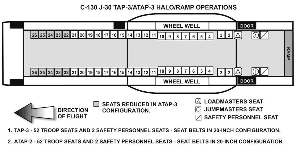
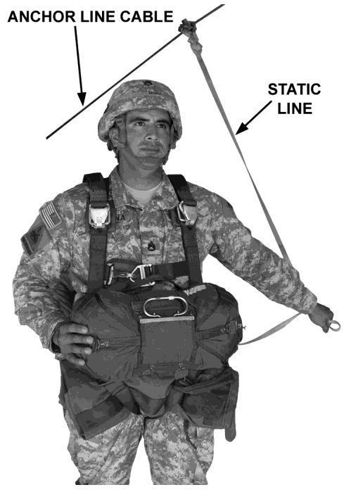
46 EXIT PROCEDURES 46

47 COMBAT OPERATIONS o All personnel will jump, including the Safeties o This applies to Mass Operations, In-Flight Rigging and Over the Ramp Operations C-17 GLOBEMASTER III CHARACTERISTICS o Swept wing, four engine, turbofan aircraft o Can carry large payloads inter-continental distances without refueling o In-flight refueling capability increases the deployment range NOTE: Over the ramp operations are not authorized on the C-17 GLOBEMASTER III. FOR AIRBORNE OPERATIONS IT COMES EQUIPPED WITH o Drop speed of 130 Knots +/- 3 Knots o 12 sets of jump caution lights (each set consists of 3 lights for a total of 36 lights o 6 Minute slow down o Four anchor line cables 27 Outboard 24 Inboard o 2 Static Line Retrieval Systems o Dedicated antenna for TACSAT o 1 USAF Loadmaster o A/C must have a deck angle of 6-7 degrees below horizontal to compensate for the stall speed of the aircraft o There is a total of 102 seats TWO BASIC SEATING ARRANGEMENTS (102 Combat Equipped Jumpers) o Mass Operations o In-Flight rigging mission 47
48 MASS OPERATIONS o 5 Supervisory Personnel 1 Primary JM 1 Assistant JM 2 Non Jumping safeties 1 USAF Loadmaster IN-FLIGHT RIGGING MISSION o 12 Supervisory Personnel 1 Primary JM 8 Assistant JM S 7 from chalk 2 Non Jumping Safeties 1 USAF Loadmaster COMBAT OPERATIONS o All personnel will jump, including the Safeties o This applies to both Mass Operations and In-Flight Rigging AIRCRAFT INSPECTION (C-130 AND C-17) o Exterior serviceable o Floors serviceable o Adequate seats/ seat belts, proper mission configuration o Excess equipment stored out of way o Emergency exits outlined in yellow o Anchor line cables o Towed parachutist retrieval system (have loadmaster operate) o Paratroop doors have no sharp edges or protruding objects nearby o Pip-pin (C-130) OR Troop door up-lock (C-17) o Manual lever for ramp secured (left door) o Jump platforms No cracks or bends (C-130) Non-skid material present Down locks seat properly (C-130) Secured to the floor (C-130) o Air deflectors (have loadmaster operate) o Jump caution lights o Interior lighting (normal/tactical) o Emergency bell/ horn (have loadmaster operate) o Emergency equipment First aid kit Fire extinguishers Oxygen masks (EPOS) o Public address system operational o Air sickness bags and ear plugs BA-22 CHARACTERISTICS o C-9 Canopy o Weighs approximately 35 lbs. o Rate of decent is feet per second o 28 flat circular canopy 48
49 o Can be OD green, brown, white and orange in color o 2 Methods of release Automatic release Manual ripcord grip assembly INSPECTION o Harness assembly o Ejector snaps o Quick fit V rings o Canopy release assemblies o Automatic opening device lanyard o Locking pins and cable o Personnel lowering device o Rear locking pins and loops o Overall inspection of parachute o Electronic tracking device ADVANCED EMERGENCY BAILOUT PARACHUTE (AEBP) CHARACTERISTICS o 26 foot extended skirt canopy o Canopy constructed of low-porosity material that is vacuum sealed o Canopy consists of: Main canopy Cross connector straps Slider Diaper Steering handles Upper risers Suspension lines made of Spectra material o Container is constructed of durable canvas weave material and is used to store the sealed canopy assembly and pilot chute. INSPECTION o Lift outer top cover flap. Check that the top closing flap tacking are present. Tuck flaps are not exposed and the color of the tape, lacing and tying, is white. o Check the rip cord pin. Ensure the pin is straight and fully seated but not shouldered. Confirm the secure tie is present. If the secure tie is not present or is broken, remove system from service for inspection. Reseat outer top cover flap. o Inspect the right links by opening the right shoulder flap and right link protector flap. Visually inspect soft links for holes, cuts, fraying, loose or broken stitching, and burns. Inspect the No. 4 connector link for burrs, cracks, sharp edges, corrosion, broken sealant, and exposed threads. Ensure torque sealant is on the nut and no threads are exposed. Close right link protector flap and right shoulder flap, ensuring the hook and pile tape is secure. o Check the front rip cord housing tacking is in place and the color of the tape, lacing and tying, is white. Check that the rip cord handle and rip cord cable are stowed in the pocket and not routed through the chest strap. Ensure large portion of rip cord handle is seated in the pocket. Ensure the swage ball is located at the end of the rip cord cable and is free from burrs, sharp edges, and cracks. After inspection, ensure that swage ball is stowed in rip cord pocket. o Inspect the left links by opening the left shoulder flap and left link protector flap. Visually inspect soft links for holes, cuts, fraying, loose or broken stitching, and burns. Inspect the No. 4 connector link for burrs, cracks, sharp edges, corrosion, broken sealant, and exposed threads. Ensure torque sealant is on nut and no threads are exposed. Visually inspect rip cord housing for burrs, cracks, corrosion, and sharp edges. Check for the presence of the rear rip cord housing tacking. Close left link protector flap and left shoulder flap ensuring hook and pile secure flap tape is secure. 49
50 o o o Check for the presence of the four quick ejector snap tacking securing the comfort pad to the chest strap quick ejector snap. Inspect the chest strap for loose or broken stitching, holes, burns, contamination, cuts, tears, and fraying. Inspect the quick ejector snap and quick fit V-ring on the chest strap for proper operation, rust, corrosion, burrs, sharp edges and cracks. Check if retainer webbing is present at the chest strap. Inspect retainer webbing for loose or broken stitching, loss of elasticity, cuts and fraying. If retainer webbing is not present or is not serviceable, replace with heavy duty retainer bands. Inspect the main lift webs for loose or broken stitching, holes, burns, contamination, cuts, tears, and fraying. Check the main lift web adjusters for burrs, cracks, sharp edges, and corrosion. Check if retainer webbings are present at the main lift webs. Inspect retainer webbings for loose or broken stitching, loss of elasticity, cuts and fraying. If retainer webbing is not present or is not serviceable, replace with heavy duty retainer bands. Check for the presence of the two quick ejector snap tacking securing the comfort pads to each leg strap quick ejector snaps. Inspect the leg straps and saddle for loose or broken stitching, holes, burns, contamination, cuts, tears, and fraying. Inspect the quick ejector snaps and quick fit V-rings on both leg straps for proper operation, rust, corrosion, burrs, sharp edges, and cracks. Check if retainer webbings are present at the leg straps. Inspect retainer webbings for loose or broken stitching, loss of elasticity, cuts and fraying. If retainer webbing is not present or is not serviceable, replace with heavy duty retainer bands. o Check the sealed canopy assembly for firmness. A soft (pillowed) AEBP indicates the sealed canopy assembly has lost its vacuum. Note. If vacuum loss occurs, the AEBP is still serviceable for the mission. After the completion of the mission, the AEBP must be repacked. Conduct an overall visual inspection of the container for seam separation, holes, cuts, tears, frays, burns, and presence of Army Parachute Log record. 50
51 Duties and Responsibilities of the DZSO and the DZSTL TC Chapter 7, & 25 DZSO The DZSO is a key member of what we refer to as a Drop Zone Support Team. The difference in the required duties of the DZSO as opposed to the DZSTL is tied to whether or not the mission is supported by an Air Force Combat Control Team. As a result of a signed Memorandum of Agreement (MOA) we are training you to perform duties for select Computed Air Release Point (CARP) operations without the presence of CCT: therefore, your designation for those operations will become Drop Zone Support Team Leader (DZSTL). DZSO PREREQUISITES Must be an officer, warrant officer, or NCO (USAF must be SRA and USMC must be CPL) o Must be a current and qualified jumpmaster o Must have observed DZSO duties on a personnel or heavy equipment drop at least once o Performed duties as ASST DZSO once DZSTL When acting as the DZSTL you are the direct representative of the ground forces commander and the air lift commander. DZSTL PREREQUISITES o Must be an Officer, Warrant Officer, NCO o Must have received training on conducting airdrop operations without the support of a CCT o For personnel and heavy equipment drops, must be a current and qualified jumpmaster DUTIES AND RESPONSIBILITES OF THE DZSO AND DZSTL The DZSO and DZSTL have specific duties and responsibilities they must perform before, during and after the airborne operation. o Attends pre-mission briefings o Coordinates with CCT if required o Opens the DZ through range control and closes it when accountability of all personnel, air items, and equipment is completed o Has the DZ fully operational one hour prior to drop time o Ensures that any water obstacle is covered by a boat detail. A boat detail is required if the water obstacle is more than four feet deep and 40 feet wide and is within 1000 meters from any portion of the surveyed DZ o Conduct ground or aerial recon of DZ prior to drop time for obstacles or safety hazards o Establishes communications with the DACO NLT one hour prior to drop time o Ensures that power is shut down to all power lines near the drop zone NLT 15 minutes prior to drop time o Co-locates with USAF CCT one hour prior to drop time and take initial wind readings o Monitor surface winds from the PI o Assistant DZSO/DZSTL monitors surface winds from the highest point of elevation or trail edge of DZ o Establish 10 minute window 12 MINUTES prior to drop time Give a GO or NO GO 2 minutes prior to drop time o Relays No Drop Signal: Surface winds exceed 13 knots within 10 minutes of the actual drop for personnel drops An unsafe act is observed on ground or in the air o DZSO/DZSTL will have positive communication with the ADZSO/ADZSTL, if needed, and the senior medic o Controls all medical evacuations o Correctly marks the drop zone o Operates all visual acquisition aids o Submits post mission reports properly o Ensure that no unauthorized vehicles are on the DZ 51
52 o All antennas will be tied down o No vehicular movement on the DZ from the time the aircraft is in sight until the last jumper has landed o Ensure all helicopters operating in the vicinity keep at least 1 km from the DZ NLT 10 min prior to TOT o Be familiar with the duties of the Malfunctions Officer/NCO IAW AR o Assist the airborne commander in the development of a written risk assessment for high and extremely high risk events The DZSO has operational responsibility for the drop zone. In addition to the DZSO s duties for drop zones, the DZSO must also: o Be positioned at the point of impact (for personnel drops) 15 minutes before drop time. The assistant DZSO is at the highest point of the drop zone or trail edge of DZ. For combination airdrop operations, the DZSO/DZSTL must follow the procedures for heavy drop operations, but observe the jumpers as they exit the aircraft o Relay a ground weather decision and CLEAR TO DROP or NO DROP signal to the lead aircraft two minutes before the drop for each pass o During night drops, ensure all lights that are on or next to the drop zone and are not a part of the Drop Zone Marking System are turned off five minutes before drop time and remain off during the drop (except those lights that mark obstacles) o Contact the pilot of the aircraft immediately after the drop and ask if any personnel or equipment did not drop. He relays this information to the airborne commander on the drop zone PERSONNEL AND SUPPORT REQUIREMENTS The Drop Zone Support Team will consist of at least two personnel. The senior person meeting the prerequisites outlined in TC , Ch. 7 will be designated as the Drop Zone Support Team Leader. Additional support personnel and equipment may be required. PERSONNEL AIRDROPS-MULTIPLE AIRCRAFT OR SINGLE AIRCRAFT OPERATIONS ON A DZ OF 2100 METERS OR MORE IN LENGTH O 1 DZSO or DZSTL and 1 Assistant DZSO or DZSTL O 2 medical personnel with 2 FLAs O Malfunctions officer with camera O Parachute recovery detail (with saw and tree climbing equipment) O Parachute turn in detail (with vehicles) O 2 radios 1 for DZSO, 1 for ADZSO (minimum) O 3 Wind measuring devices 1. Anemometers Services should only use approved anemometers to measure surface winds during all personnel and cargo parachute operations. THE APPROVED ANEMOMETERS ARE THE DIC-3, TURBOMETER, AND AN/PMQ-3A. The DIC-3, and Turbometer cannot be calibrated; they must be given an expedient check just before use 2. Ensure fresh batteries are installed in the anemometer 3. Check the anemometer in a no wind condition such as in a vehicle cab or a building. Turn on the anemometer and, if any reading other than zero registers, the anemometer is not fit for use and must be discarded 4. Use a three anemometer check by comparing the reading on three anemometers in identical conditions. Discard the one anemometer that doesn t read the same as the other two 5. The Turbometer must be held within 20 degrees of wind line with the wind entering the rear of the meter to ensure accurate readings 6. Calibration requirements for the AN/PMQ-3A will be conducted in accordance with appropriate TMs. Other anemometers not tested and recommended for use should be employed only after a command initiated risk assessment is completed. Regardless of the method or device used to measure DZ winds, the airborne commander is responsible for ensuring winds on the DZ do not exceed 13 knots during static line personnel airdrops o 2 Compasses 52
53 o o o o o o o o o 2 sets of Night Vision Goggles VS-17 Panels/Lights Binoculars, strobe light, signal mirror Smoke Grenades (as required) Vehicles (as required) Road Guards (as required) Pi-ball equipment with helium source (If applicable) Military Police (If Applicable) Boat Detail (If Applicable) PERSONNEL AIRDROPS-SINGLE AIRCRAFT OPERATIONS ON A DZ LESS THAN 2100 METERS IN LENGTH O 1 DZSO or DZSTL o 1 Radio o 1 Compass o 3 Wind measuring devices (above guidance concerning anemometers applies here as well) o 1 Medic with 1 FLA o All other requirements remain unchanged DZSTL ADDITIONAL SUPPORT REQUIREMENTS o Minimum of 11 Omni-directional white lights o 1 white air traffic control light and/or flares o 1 red lens for air traffic control light and/or flares PUBLICATIONS o INSTALLATION RANGE REGULATION o MOST RECENT MAP SHEET OF THE AREA o COPY OF UNIT ASOP o ANY OTHER LOCALLY REQUIRED REGULATIONS o COPY OF DROP ZONE SURVEY o AR 59-4 JOINT AIRDROP RECORDS, MALFUNCTIONS INVESTIGATIONS AND ACTIVITY REPORTING o TC STATIC LINE PARACHUTING TECHNIQUES AND TRAINING o BLANK FORMS (FLASH REPORT, etc.) PRE-MISSION BRIEFING Prior to the airborne operation the DZSO/DZSTL must attend a detailed pre-mission briefing. If possible this should be done directly with the aircrew. If it is not possible, the units S3 Air should provide the minimum essential information. The following checklist should be used as a guide to insure all the pertinent information has been provided: o JA/ATT (Joint Airborne/Air Transportability Training) Mission sequence number o Type and number of aircraft o Type of drop-pe, CDS, HE o Type of release-carp, GMRS, VIRS o Type of parachutes o Verify DZ name and location o Verify current DZ Survey Data o TOT(s) or Block time o No Drop Procedures o Number of jumpers or bundles o DZ Markings RAM Panels/ lights Smoke/ flares Emergency no drop procedures 53
54 Mission cancellation indication o DZ support Communications available Frequencies/ call signs Visual acquisition aids NAV AIDS o Aircraft/ Mission commanders name, rank, unit and telephone number o DZSO/DZSTL name, rank, unit and telephone number o Post mission reports DROP ZONE SURVEYS There are 2 types of drop zone surveys o Tactical Assessment of Drop Zone o AF form 3823 AF 3823 All information we need concerning the drop zone is on the AF form The Air Force has a listing of all available drop zones that were approved for use. The list is called the Assault Zone Availability Report (AZAR). This list is attainable through the Air Force. AZAR is compiled from inputs provided by 21 st AF, McGuire AFB, NJ and 22 nd AF, Travis AFB, CA. It identifies drop zones, landing zones, and extraction zones available in CONUS for use by the Air Mobility Command. o Instructions for filling out AF Form 3823 can be found in the Pathfinder FM o All obstacles must be identified within a 1000 meters of DZ An aerial recon must be conducted to identify the hazards o Once AF Form has been completed it must be verified by the first O-6 of the supported unit o Completed AF form 3823 is good for 5 years from date of approval signature The columns of the AF form 3823 are explained below and all blocks require an entry including N/A if applicable. 1a. DZ name 1b. ZAR index number (AF drop zone website reference number) 2a. Country 2b. State 3. Map sheet and series information 4a1. Date DZ was surveyed 4a2. Name and rank of surveyor 4a3. Contact phone number 4a4. Surveyor s name 4b. DZ approval or disapproval by mission type and day use 4c. Date approved for ground operations 4d. Date of safety of flight review 4e. Date of MAJCOM approval DZ survey is good for five years from this date 5a. Controlling unit or agency 5b. Memorandum of understanding / land use agreement 5c. Contact phone number 5d. Range control frequencies (FM/ UHF) 5e. Contact phone number 6a-c. Dimensional data (length, width, radius) 6d-f. PI distances from the lead edge of the DZ 7a-d. DZ axis data (direction of flight) 8a-d. Ground point elevations 9a-f. DZ coordinates 9g. Point of origin data (prominent terrain feature used to help find PI) 54
55 9h. DZ center point and PI grid locations 9i. DZ corners (grid coordinates for the corners of the DZ) 10. DZ diagram or digital photographic 11. Remarks (all hazards/ restrictions and pertinent information about the DZ) 12. Photograph available 13. Low level routes available Note: When performing a safety of flight review on a foreign DZ, as much information as possible should be filled in on the AF form At a minimum, the following items must be filled in: items 4d, 6a, 6b, 7, 9a-f, and 9h. A copy of the foreign DZ should be attached to the safety of flight review. 55

56 56
57 57
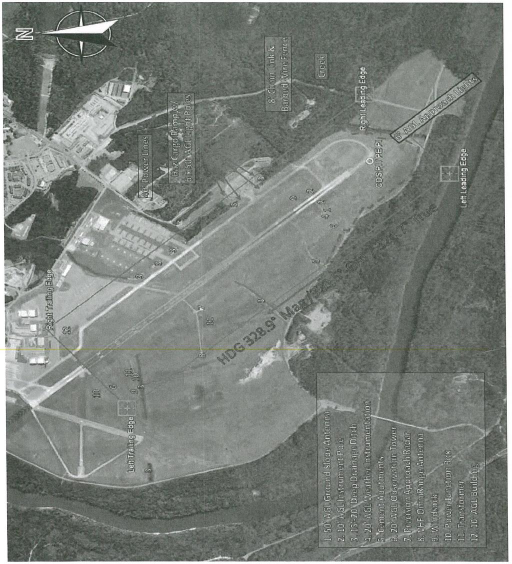
58 58
59 AF FORM 4304 STRIKE REPORT The AF form 4304 is essentially a score card for the Air Force. Since the release point is computed by the aircrew on a CARP drop zone, the Air Force must have some documentation on the crew s performance. The clock direction and distance from the PI will be recorded on the AF form 4304 and forwarded to higher headquarters. Upon completion these should be forwarded through your unit S3. o A PI strike is given on the Strike report if first parachute suspended item lands within 25 yards of the point of impact o Success if 90% of parachute items land on surveyed drop zone The following is a list of the blocks and an explanation of the contents on the AF form 4304: 1. DATE: Enter date and year. Use either calendar or Julian date. When a time is required use local or GMT consistent with the date. 2. LOCATION: Enter DZ name 3. CCT AND UNIT: DZSTL name and unit 4. DZ/LZ CONTROL OFFICER AND UNIT 5. DROP ZONE SAFETY OFFICER AND UNIT 6. LINE NO: One line filled out for each pass of each aircraft. No drop passes should use a line number also. The remarks column should reflect the reason for the no drop situation. 7. TYPE ACFT: Mission design series 8. UNIT: Unit of aircraft 9. CALL SIGN: Call sign of lead and, if applicable, formation position number 10. TYPE MISSION; Refer to legend for abbreviations. Your initial appropriate training will dictate what type of drop zone you are qualified to operate 11. ETA: Estimated time of arrival, estimated TOT, or S3 air brief. Keep the unit of time consistent throughout the form 12. ATA/ATD: Actual time of every pass and actual time of departure 13. STRIKE REPORT: a. YDS: Distance first jumper. Container/ pallet lands b. CLOCK: Use direction of flight as the 12 o clock and its back azimuth as the 6 o clock, estimate direction from PI to first jumper/ container/ pallet. If item and conditions permit, the actual measurement is preferred 14. LZ: Mark the S box if a landing occurred between the beginning of the touchdown zone and the first 500 feet. If the landing was not successful (i.e., go-around), short of the touchdown zone or 500 feet beyond the beginning of the touchdown zone, mark the U box and provide comments in the REMARKS box 15. SURF WIND: Surface wind direction in degrees, and velocity in knots 16. SCORE METHOD: Refer to LEGEND for abbreviations 17. MEAN EFFECTIVE WIND: Time taken and at what altitude a. TIME: Self-explanatory b. ALT: Should be drop altitude c. DIR & VEL: Wind direction in degrees and velocity in knots 18. REMARKS: Enter remarks as appropriate 59
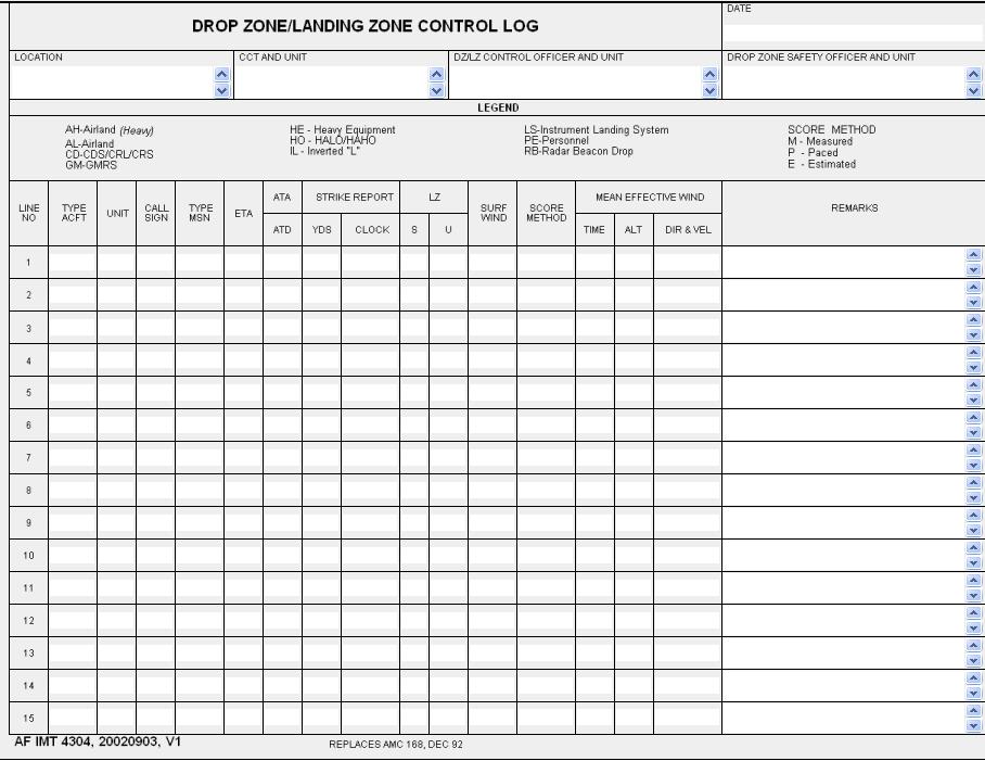
60 60
61 Computed Air Release Point (CARP) TC Chapters 7, & AFI CARP DROP ZONES CARP drop zones are used by high performance fixed wing aircraft. The navigator on board the aircraft calculates the release point. The DZSO or the DZSTL has the responsibility of marking the drop zone and ensuring that it is of the proper size to support the mission. OPERATION TYPES o Personnel Drops o CDS Drops o Heavy Equipment Drops CARP PROBLEM SETUP Planning Altitude Width Length 1 N A N XXXXXXX A XXXXXXX S XXXXXXX Total PLANNING ALTITUDES o Personnel 1000 feet AGL o Heavy Equipment 1100 feet AGL (1) MINIMUM SIZE REQUIREMENTS FOR ONE JUMPER OR PLATFORM o Personnel 600 yards in width x 600 yards in length o Heavy Equipment 600 yards in width x 1000 yards in length o CDS Requirements can be found in AFI Drop Zone and Landing Zone Operations 61
62 SIZE ADDITIONS o (N) Night ( ) Add an additional 100 yards to both the length and the width Hours of darkness are generally from o (A) Altitude Add an additional 30 yards to both the length and width for every 100 feet over the minimum planning altitude o (N) Not in Trail Formation C-130: 100 yards to width (one time only) C-17 HE: 100 yards to width (one time only), can t have more than 3 C-17 s in a formation C-17 PE: 640 yards to width for 2x C-17 s; 1200 yards to width for 3x C-17 s, can t have more than 3 C-17 s in a formation, CANNOT BE IN TRAIL ***This is only applicable when using center PI*** o (A) Additional Jumpers or HE Platforms Add an additional 75 yards to the length for each additional jumper Add an additional 400 yards to the length for each additional HE platform on a C-130 Add an additional 500 yards to the length for each additional HE platform on a C-17 or C-5 DOOR EXITING PROCEDURES FOR PERSONNEL o ADEPT Option 1(Alternate Door Exiting Procedures for Training) One door, one pass; half the jumpers minus 1 o ADEPT Option 2 One door followed by the other door, one pass; Total jumpers minus 1 o Mass Exit For even number of total jumpers, divide in half. For odd number of total jumpers, divide in half and use lower number. o (S) Station Keeping Equipment (SKE) When used, add 400 yards to width (one time only) Generally used for formations / multiple aircraft; not in trail or in trail, C-130 s or C-17 formations dropping only CDS or HE Compare SKE with not in trail; use whichever is larger, cancels out the smaller POINT OF IMPACT (PI) LOCATIONS The PI is determined by the type of operation being executed. All PI s will be measured from the lead edge of the drop zone and centerline. o CDS (C-130) Day o Personnel (C-130 or C-17) Minimum of 200 yards DAY Night Minimum of 300 yards Minimum of 250 yards NIGHT Minimum of 350 yards o CDS (C-17) No GPS Day o Heavy Equipment (C-130 or C-17) Minimum of 225 yards Day Night Minimum of 500 yards Minimum of 275 yards Night Minimum of 550 yards 62
63 HE Point of Impact Tree Trail Edge 550y 500y - Night - Day Direction Of Flight PE CDS 350y 300y 275y 250y 225y 200y Lead Edge C-17 C-130 CARP PI MARKINGS o PRIMARY MEANS OF MARKING THE DROP ZONE IS A RAISED ANGLE MARKER (RAM). o A RAM must be triangular is shape, and must measure 6 feet in length by 6 feet in width and be raised to at least a 60 degree angle. o Code Letters for Authentication J, C, A, R & S o Circular or Random Approach DZ H & O DAY TIME MARKINGS o Minimum of nine panels for the code letter o At least 35 feet x 35 feet o Only the PI Must be Marked o Center the top of the code letter at the base of the RAM o Color and code letter will be pre-coordinated and the color will be contrasting with the surrounding area NIGHT TIME MARKINGS o Minimum of nine Omni-directional white lights for the code letter o At least 35 feet x 35 feet o If used, flanker lights will be Omni-directional white lights located 250 meters to the left and right abeam of the PI 63

64 o If used, trail edge of the DZ or 1000 meters centerline from the PI, whichever comes first, must be marked with an amber rotating beacon. Beacons are not considered lights 64
65 CODE LETTERS CONTROL CENTER The control center is where the DZSO/ DZSTL is located to control and observe the operation. The location is determined by the type of operation. CDS o 200 yards from the PI at the 6 o clock PERSONNEL o At the PI HEAVY o 300 yards from the PI at the 6 o clock AWADS, HIGH VELOCITY, CEILINGS OF 600 FEET OR LESS and FREE DROPS o Off the DZ at the best vantage point AWADS Adverse Weather Aerial Delivery System NO DROP SITUATIONS It may become necessary for you as the DZSO/DZSTL to temporarily halt a jump or to declare a no drop or mission cancellation. Declaring a No Drop: o Initiate red smoke, Red Always Means No Drop o Scramble or remove the code letter, if present o Other means of communicating a no drop could be an air traffic control light, signal mirror, flares or any specific means covered by the crew in the pilot brief. The Universal Temporary Closing of the DZ signal is to place two parallel bars made of four VS- 17 panels each, perpendicular to the direction of flight. The Universal Mission Cancellation signal is to form an X out of eight VS-17 panels on the PI. 65
66 AUTHORIZED WIND MEASURING DEVICES Anemometers Services should only use approved anemometers to measure surface winds during all personnel and cargo parachute operations. THE APPROVED ANEMOMETERS ARE THE DIC-3, TURBOMETER, AND AN/PMQ-3A. The DIC-3, and Turbometer cannot be calibrated; they must be given an expedient check just before use O O O O O O Ensure fresh batteries are installed in the anemometer Check the anemometer in a no wind condition such as in a vehicle cab or a building. Turn on the anemometer and, if any reading other than zero registers, the anemometer is not fit for use and must be discarded Use a three anemometer check by comparing the reading on three anemometers in identical conditions. Discard the one anemometer that doesn t read the same as the other two The Turbometer must be held within 20 degrees of wind line with the wind entering the rear of the meter to ensure accurate readings Calibration requirements for the AN/PMQ-3A will be conducted in accordance with appropriate TMs. Other anemometers not tested and recommended for use should be employed only after a command initiated risk assessment is completed. Regardless of the method or device used to measure DZ winds, the airborne commander is responsible for ensuring winds on the DZ do not exceed: O 13 knots during static line personnel airdrops (land) O 17 knots during static line personnel airdrops (water) o 13 knots during heavy equipment airdrops without ground disconnects 66
: This is a calibrated, hand held wind measuring device, used for measuring ground wind.")
67 o 17 knots during heavy equipment airdrops with ground disconnects Plotting the 1 minute and 30 second reference points on a map R/D 30 SEC R/D 1 MIN Lead Edge FRYAR DZ Lead Edge L/D 30 SEC L/D 1 MIN DZST EQUIPMENT FAMILIARIZATION AN/PMQ-3A (anemometer): This is a calibrated, hand held wind measuring device, used for measuring ground wind. Oriented correctly, it will give wind direction in degrees, by pressing the trigger. It is capable of reading the wind from 0 to 15 knots on the low scale and from 0 to 60 knots on the high scale. Select High or low using the High/Low selector switch. The anemometer must be calibrated every six months. NSN: Turbo Meter: This is an electronic wind speed indicator. It provides wind speed accurately, and is pocket size for convenience. The turbo meter has four scales which are displayed on a three digit light Emitting Diode display. The scales are knots per hour, feet per second, meters per second, and miles per hour. For best results, keep axis of turbo meter within 20 degrees of the direction of wind. NSN: T Amber Rotating Beacon: Electric driven light which provides amber rotating light for trail edge marker on a night CARP drop zone. NSN: Local purchase item. 67
68 VS-17 Marker Panel Aerial: Two sided panel. One side is fluorescent orange, sometimes referred to as international orange. The other side is cerise or commonly referred to as red. The panel is 2 feet wide and 6 feet long. It has six tie down points used to attach the panel to stakes. It also has three snap fasteners on the short ends in the stow pocket. It should be folded up so the olive drab (OD) green is showing. The color of the panel used should best contrast the surrounding area. NSN: Light, Marker, Ground Obstruction: Also known as the beanbag light. It is powered by one BA-200. The color of the light can be changed with the use of interchangeable colored plastic domes. These can be used in light holes or on the surface, secured with tent pegs, or by filling the bottom with sand or rocks. NSN: Mirror, Emergency signaling, type II: The signal mirror when used properly, can be used to signal aircraft by reflecting sunlight. There is a set of instructions on the back of the signal mirror for proper use and aiming. The signal mirror can still be used on hazy days. One misconception is that it can only be used when facing the sun. It can be used in all directions and can be seen as far as the horizon will go. NSN: Pilot Balloon: the pi-ball is a ten or thirty gram rubber balloon that, when filled with helium to the specified circumference is used to measure the mean effective wind which is the average wind from the ground to drop altitude. NSN: Balloon Meteorological 10 Gram , Balloon Meteorological 30 Gram gram 57 inch day, 74 inch night 30 gram 75 inch day, 94 inch night Lighting Unit (Pi-ball): This light is attached to the pi-ball for night operations. The pi-ball is inflated to a greater dimension to compensate for the weight of the light so that the same ascension rate is achieved. The pi-ball light has a wet cell battery that is activated by water, or fluid. When temperatures fall below 50 degrees the pi-ball light activates faster by using warm water. NSN: Drift Scale: Slide type scale that uses a 90 degree angle to measure the ascent of the pi-ball for determining the mean effective wind. NSN: Locally produced by TASC (a protractor with a string through the center with a weight can be used). Also for this purpose, the Thedolite, NSN , Pocket Transit (with built in clinometer) NSN , and the Clinometer, NSN DZST GUIDE TO REFERENCES o AFI o AFI o AFI 11-2c130v3 o AFI 11-2c17v3 o TC o FM o TC o Memorandum of agreement, Airdrop operations without combat control teams (CCTs), dated 27 June
69 DEFICIENCIES TYPES OF DEFICIENCIES MAJOR DEFICIENCY: (-35 points) could cause loss of life, limb, eyesight or military equipment OR questions the integrity of how the parachute was packed. EXAMPLE) TABBED PORTION CHEST STRAP NOT FACING CHEST STRAP FRICTION ADAPTER EXAMPLE) LEFT CONNECTOR SNAP RETAINING TIE MISSING MINOR DEFICIENCY: (-11 points) could cause possible injury to jumper, damage to equipment, or discomfort when worn. EXAMPLE) MAIN LIFT WEB TUCK TAB ASSEMBLY NOT PROPERLY ASSEMBLED EXAMPLE) SADDLE INVERTED CATEGORIES OF DEFICIENCIES The cards will have two categories of deficiencies: 1. JUMPER RIGGED DEFICIENCIES: Normal donning deficiencies that the jumper will create when donning the parachute. EXAMPLE) LEG STRAPS TWISTED EXAMPLE) CHEST STRAP MISROUTED AROUND MAIN LIFT WEB 2. PRE-RIGGED DEFICIENCIES: Deficiencies that the instructors have already placed in the parachute rigs. EXAMPLE) FOREIGN MATTER IN LEFT CANOPY RELEASE ASSEMBLY EXAMPLE) UNIVERSAL STATIC LINE MODIFIED CUT WHEN CALLING DEFICIENCIES, TELL US THREE THINGS 1. WHAT IS IT? Item of equipment (USE PROPER NOMENCLATURE!!) 2. WHERE IS IT? In relation to the jumper (left / right, front/rear) 3. WHAT S WRONG WITH IT? Improperly assembled / foreign matter / reversed etc. It can be in any order! However, if you say exactly what is on the cards there is no room for the instructor to misinterpret what it is you are saying. CORRECTIONS: CORRECTING SEQUENCE: Not required to call correction when correcting a sequence violation, go back to where you were last correct and continue. HOWEVER, calling correction will regain the instructor s attention back on you. 69
70 CORRECTING A CALLED DEFICIENCY : MUST call correction when correcting a deficiency. EX) left leg strap twisted correction, right leg strap twisted NOTES: These are mistakes that are commonly seen during JMPI circles. MASKING THE STATIC LINE - FISH HOOKING - PINCHING - OVERLAPPING OF STATIC LINE STRANDS - CAN NOT RAKE STATIC LINE LIKE ITEMS- If the jumpmaster sees Foreign matter in right canopy release assembly, it can also be in the left canopy release assembly, Hollywood or Combat equipped jumper. This goes for all Like Items of equipment USE PROPER SEQUENCE EVEN WHEN THERE IS A DEFICIENCY EXAMPLES: WAISTBAND / WAISTBAND ADJUSTOR PANEL MISROUTED BEHIND HORIZONTAL BACKSTRAP NO QUICK RELEASE IN WAISTBAND GIRTH HITCH UNIVERSAL STATIC LINE MODIFIED REVERSED LAST STRAND OF UNIVERSAL STATIC LINE MODIFIED MISROUTED FROM LEFT OUTER STATIC LINE STOW BAR LEFT/RIGHT ADJUSTABLE D RING ATTACHING STRAP REVERSED NO ABBREVIATING! EXAMPLE) HPT LOWERING LINE MISROUTED NO CASTING SPELLS! Advanced Combat Helmet, Hook Pile Tape Lowering Line YOU CAN NOT call deficiencies early, EXAMPLES) - CALLING SADDLE INVERTED WHEN INSPECTING THE LEG STRAPS - LEFT / RIGHT LEG STRAP MISROUTED AROUND SADDLE - CALLING AVIATOR KIT BAG MISSING BEFORE TRACING LEG STRAPS Must call all deficiencies prior to giving the seal of approval for the corresponding jumper to get credit for that deficiency. GHOST JUMPERS Builds muscle memory, Visualization TRANSITIONS Don t think I have to move faster, think I have to move SMOOTHER STUDY NOMENCLATURE KNOWING SIDES (Writing a L on your right hand doesn t work) Deficiencies that you see in the course are the only ones we will test you on; that doesn t mean others do not exist EXAMPLE) STATIC LINE MISROUTED THROUGH CHINSTRAP WEAR EQUIPMENT LIKE YOU SHOULD: Rigs are very snug on test day REHAB the parachutes: quick releases, static line, excess webbing in leg straps and horizontal back straps, ETC If you don t REHAB, you re setting your Buddy up for failure! 70
71 Do not sacrifice sequence for speed. The time gained may very well jeopardize the jumper s safety. JMPI TEST 3 JUMPERS (0-5 Deficiencies per Jumper) a) T-11 / MC-6 CBT b) T-11 / MC-6 HWD c) T-11 / MC-6 HWD Call all deficiencies 5 Minutes for all three jumpers Proper Sequence GRADING IMPROPER SEQUENCE -35 POINTS MISSED MINOR DEFICIENCY -11 POINTS MISSED MAJOR DEFICIENCY -35 POINTS IMPROPER HAND PLACEMENT -35 POINTS FAILURE TO INSPECT -35 POINTS OVER ON TIME -35 POINTS MASKING STATIC LINE -35 POINTS IMPROPER COMMAND OR NOT CALLING A COMMAND -35 POINTS JMPI Deficiencies The deficiencies below are some of the more common deficiencies that a Jumpmaster will come across. This is not to say that other deficiencies don t exist. Also, this list may or may not contain all the deficiencies a student will encounter while at the U.S. Army Jumpmaster School. Some of the verbiage or point values below may also differ from what is printed on the deficiency cards used during training. FRONT ADVANCED COMBAT HELMET FRONT RIGHT/LEFT BOLT END EXPOSED -35 FRONT TRAPEZOID PAD MISSING -35 EXCESS WEBBING FRONT RIGHT / LEFT ADJUSTABLE STRAP NOT SECURED -11 CHINSTRAP TWISTED -11 CANOPY RELEASE ASSEMBLIES RIGHT / LEFT CANOPY RELEASE ASSEMBLY NOT PROPERLY ASSEMBLED -35 FOREIGN MATTER RIGHT / LEFT CANOPY RELEASE ASSEMBLY -35 T-11 PARACHUTE HARNESS CHEST STRAP MISROUTED AROUND MAIN LIFT WEB -11 CHEST STRAP TWISTED
72 EXCESS WEBBING CHEST STRAP NOT SECURED -11 NO QUICK RELEASE IN CHEST STRAP -35 QUICK RELEASE IN CHEST STRAP NOT SECURED -11 FREE RUNNING END CHEST STRAP NOT S ROLLED OR ACCORDIAN FOLDED -11 TABBED PORTION CHEST STRAP NOT FACING TOWARDS CHEST STRAP FRICTION ADAPTER -35 WAISTBAND MISROUTED UNDER HORIZONTAL BACKSTRAP -11 WAISTBAND MISROUTED UNDER RIGHT / LEFT MAIN LIFT WEB -11 WAISTBAND MISROUTED OVER RIGHT / LEFT EQUIPMENT RING -11 WAISTBAND NOT ROUTED THROUGH RIGHT / LEFT WAISTBAND RETAINER -11 WAISTBAND TWISTED -11 NO QUICK RELEASE IN WAISTBAND -35 IMPROPER QUICK RELEASE IN WAISTBAND (CPT'S BARS / DEAD MAN'S HITCH) -35 WAISTBAND ADJUSTER PANEL TWISTED -11 WAISTBAND ADJUSTER PANEL MISROUTED UNDER HORIZONTAL BACKSTRAP -11 MAIN LIFT WEB MISSIZED -11 RIGHT / LEFT MAIN LIFT WEB TUCK TAB ASSEMBLY NOT PROPERLY ASSEMBLED -11 RIGHT / LEFT MAIN LIFT WEB TUCK TAB ASSEMBLY SNAP FASTENER NOT SECURED -11 T-11 RESERVE ARMY PARACHUTE LOG RECORD MISSING FROM RESERVE -35 DIRECTIONAL ARROW UPSIDE DOWN -35 CURVED PIN LANYARD TWISTED -35 RIGHT / LEFT SIDE TUCK TAB NOT SECURED -35 CURVED PIN LANYARD NOT SECURED TO RIPCORD ASSEMBLY -35 RIGHT / LEFT CONNECTOR SNAP RETAINING TIE MISSING -35 EXPOSED CANOPY RESERVE -35 SPREADER BAR TIE NOT SECURED -35 LEGSTRAPS / UNIVERSAL PARACHUTIST RECOVERY BAG LEG STRAPS CROSSED -11 RIGHT / LEFT LEG STRAP TWISTED -11 RIGHT / LEFT LEG STRAP EXCESS WEBBING NOT SECURED -11 RIGHT / LEFT LEG STRAP EJECTOR SNAP WILL NOT SEAT -35 EXCESS WEBBING RIGHT / LEFT LEG STRAP MISROUTED OVER LEG STRAP RETAINER -11 RIGHT / LEFT LEG STRAP NOT ROUTED LEG STRAP RETAINER -11 UNIVERSAL PARACHUTIST RECOVERY BAG UPSIDE DOWN -11 UNIVERSAL PARACHUTIST RECOVERY BAG MISSING -11 UNIVERSAL STATIC LINE MODIFEID GIRTH HITCH UNIVERSAL STATIC LINE MODIFIED REVERSED -35 UNIVERSAL STATIC LINE MODIFIED CUT
73 UNIVERSAL STATIC LINE MODIFIED MISROUTED THROUGH RIGHT / LEFT RISER ASSEMBLY -35 UNIVERSAL STATIC LINE MODIFIED MISROUTED UNDER RIGHT / LEFT RISER ASSEMBLY -35 UNIVERSAL STATIC LINE MODIFIED MISROUTED AROUND RIGHT / LEFT INNER STATIC LINE STOW BAR -35 UNIVERSAL STATIC LINE MODIFIED MISROUTED AROUND RIGHT / LEFT OUTER STATIC LINE STOW BAR -35 LAST STRAND UNIVERSAL STATIC LINE MODIFIED MISROUTED FROM LEFT OUTER STATIC LINE STOW BAR -35 REAR OF ADVANCED COMBAT HELMET REAR LEFT / RIGHT BOLT END EXPOSED -35 REAR TRAPEZOID PAD MISSING -35 EXCESS WEBBING REAR LEFT / RIGHT ADJUSTABLE STRAP NOT SECURED -11 NAPE PAD MISSING -11 NAPE PAD REVERSED 11 - RISER ASSEMBLIES LEFT / RIGHT RISER ASSEMBLY TWISTED -35 ARMY PARACHUTE LOG RECORD MISSING FROM RISER ASSEMBLY -35 MAIN PACK TRAY DIAGONAL BACK STRAPS MISSIZED -11 LEFT / RIGHT DIAGONAL BACK STRAP RETAINER NOT ROUTED THROUGH DIGONAL BACK STRAP KEEPER -11 EXCESS WEBBING RIGHT / LEFT HORIZONTAL BACK STRAP NOT SECURED -11 HORIZONTAL BACK STRAP NOT ROUTED THROUGH RIGHT / LEFT HORIZONTAL BACK STRAP RETAINER -11 HORIZONTAL BACK STRAP RETAINER NOT ROUTED THROUGH RIGHT / LEFT HORIZONTAL BACK STRAP KEEPER -11 STATIC LINE SLACK RETAINER BAND MISSING FROM STATIC LINE SLACK RETAINER LOOP -35 MAIN CLOSING LOOP CUT -35 SADDLE LEFT / RIGHT LEGSTRAP MISROUTED AROUND SADDLE -11 SADDLE INVERTED -11 MODULAR AIRBORNE WEAPONS CASE SNAP FASTENER YELLOW SAFETY LANYARD NOT SECURED -35 FREE RUNNING END ADJUSTING STRAP NOT PROPERLY SECURED UNDER POUCH ATTACHMENT LADDER SYSTEM WEBBING -11 ADJUSTING STRAP NOT PROPERLY ROUTED THROUGH FRICTION ADAPTER -11 QUICK RELEASE BUCKLE NOT SECURED -11 FREE RUNNING END COMPRESSION STRAP NOT SECURED -11 SNAP FASTENER SLIDE FASTENER AND TABBED THONG NOT SECURED -35 UPPER TIE DOWN TAPE NOT PROPERLY ROUTED THROUGH SLIDE FASTENER AND TABBED THONG
74 WEAPON REVERSED -11 WEAPON UPSIDE DOWN -11 UPPER TIE DOWN TAPE MISROUTED THROUGH EQUIPMENT RING (FRONT TO BACK / EQ RING) -11 UPPER TIE DOWN TAPE NOT ROUTED THROUGH EQUIPMENT RING (D RING / MAIN LIFT WEB) -11 SPRING MISSING FROM UPPER SPRING STOP -11 HOOK AND PILE TAPE OF ADJUSTABLE NOSE CONE NOT SECURED -11 MOLLE AND HOOK PILE TAPE LOWERING LINE FREE RUNNING END ADJUSTABLE SHOULDER CARRYING STRAP NOT SECURED PROPERLY -11 EJECTOR SNAP HOOK PILE TAPE LOWERING LINE REVERSED -35 HOOK PILE TAPE LOWERING LINE MISROUTED UNDER LEFT ADJUSTABLE SHOULDER CARRYING STRAP -11 EJECTOR SNAP HOOK PILE TAPE LOWERING LINE WILL NOT SEAT -35 HOOK PILE TAPE LOWERING LINE MISROUTED THROUGH CARRYING HANDLE OF MODULAR AIRBORNE WEAPONS CASE -11 FREE RUNNING END EQUIPMENT RETAINER STRAPS ROLLED -11 GIRTH HITCH HOOK PILE TAPE LOWERING LINE ROUTED EAST / WEST -11 NO QUICK RELEASE IN EQUIPMENT RETAINER STRAPS -11 RELEASE HANDLE LANYARD TWISTED -11 RIGHT / LEFT ADJUSTABLE D RING ATTACHING STRAP REVERSED -11 RIGHT / LEFT ADJUSTABLE D RING ATTACHING STRAP TWISTED -11 EQUPMENT RETAINER STRAP TWISTED -11 GREEN ATTACHING LOOP ROUTED OVER RIGHT / LEFT GROMMET -11 GREEN ATTACHING LOOP MISROUTED THROUGH RIGHT / LEFT GROMMET -11 RELEASE HANDLE CABLE NOT ROUTED THROUGH RELEASE HANDLE CROSS STRAP -11 RELEASE HANDLE LANYARD MISROUTED AROUND RELEASE HANDLE CROSS STRAP
75 Practical Work in the Aircraft TC Chapters 5, 10 & 16 FOUR TIME WARNINGS o 20 minute a. 20 minute time warning begins and ends at shoulder level in closed fist. As the jumpmaster issues the verbal command TWENTY MINUTES extend hands and arms forward while spreading the fingers and thumbs, then return to shoulder level in closed fists. This motion will be repeated twice. o 10 minute a. 10 minute time warning begins and ends at shoulder level in closed fist. As the jumpmaster issues the verbal command TEN MINUTES extend hands and arms forward while spreading the fingers and thumbs, then return to shoulder level in closed fists. o 1 minute a. The jumpmaster will issue the one minute time warning by extending the lead arm toward the jumpers and raising the index finger, sounding off with ONE MINUTE. o 30 seconds a. The jumpmaster will issue the 30 second time warning by extending his lead arm toward his jumpers, with the index finger and thumb approximately 1 inch apart, and sound off with 30 SECONDS. NINE JUMP COMMANDS o Get Ready a. It begins at shoulder level, all fingers and thumbs extended and joined, palms facing the jumpers. As the jumpmaster issues the verbal command GET READY, extend both arms straightforward until the elbows lock, ensuring that the palms remain facing the jumpers. o Outboard Personnel, Stand-Up a. This jump command is executed in two parts. The first part begins at shoulder level, index and middle fingers extended and joined, remaining fingers and thumbs curled to the palm. As the jumpmaster issues the verbal command "OUTBOARD PERSONNEL" the arms are extended down to the sides at a 45-degree angle. As the jumpmaster issues the verbal command "STAND UP", first extend and join all fingers and thumbs, rotate the hands so the palms face up, and then raise the arms straight overhead keeping the elbows locked. o Inboard Personnel, Stand-up a. This jump command is also executed in two parts. The first part begins at shoulder level, centered on the chest, once again, index and middle fingers extended and joined, all remaining fingers and thumbs curled to the palm. As the jumpmaster issues the verbal command "INBOARD PERSONNEL", the arms are extended towards the inboard seats until the elbows lock. As the jumpmaster issues the verbal command "STAND UP" the arms are first moved back to the sides and down, all fingers and thumbs are extended and joined, 75
76 o o o o o the hands are rotated so the palms face up, and then raise the arms straight overhead keeping the elbows locked. Hook Up a. This jump command may begin in two different ways. It may begin at shoulder level or it may begin with the arms extended straight overhead. A hook will be formed in the index finger of each hand. All remaining fingers and thumbs form fists. As the jumpmaster issues the verbal command HOOK UP, move the arms in a pumping motion, up and down, or down and up. This motion must be repeated a minimum of three times. Check Static Lines a. This is a plural command since there will normally be more than one static line attached to the anchor line cable. This jump command begins at eye level, index fingers and thumbs forming an "O", remaining fingers extended and joined, palms facing each other and the knife edge of the hands facing the jumpers. As the jumpmaster issues the verbal command CHECK STATIC LINES, extend the arms straight forward to a near elbow locked position, ensuring the knife-edge of the hands remain facing the jumpers. This motion must be repeated a minimum of three times. b. After this command is given, it will be followed by a secondary command of; Last two jumpers turn and face the skin of the aircraft. Second to last jumper trace the last jumper s static line. Check Equipment a. This jump command may begin in two different ways. It may begin with the fingertips centered on the chest, all fingers and thumbs extended and joined, palms facing the chest or it may begin with the arms extended to the sides at shoulder level, all fingers and thumbs extended and joined, palms facing the jumpers. As the jumpmaster issues the verbal command CHECK EQUIPMENT, extend the arms to the sides at shoulder level, or bend the arms at the elbow, bringing the fingertips to the center of the chest. This motion must be repeated a minimum of three times. b. After issuing this command, the jumpmaster will observe their stick of jumpers as they check their equipment by leaning to the left and then to the right. Once the jumpmaster sees that all movement has ceased, they will give their fellow jumpmaster a thumbs up. However, for testing purposes, they will issue this thumbs up to the safety. At this time the jumpmaster is free to check their equipment. They will check at a minimum, the front rim of the advanced combat helmet, their chinstrap, the quick release in the chest strap, both leg straps, and the ejector snap for the hook pile tape lowering line. Sound off for Equipment Check a. The jumpmaster will form their hands into cups and place the thumbs behind the ears, with the remainder of the hands cupped alongside the outer rim of the helmet. As the jumpmaster issues the verbal command "SOUND OFF FOR EQUIPMENT CHECK" and drop the hands and wait until they receives "ALL OKAY JUMPMASTER" from the number one jumper. Stand By a. This jump command begins at shoulder level, index and middle finger extended and joined, all remaining fingers and thumbs are curled to the palm. 76
77 o As the jumpmaster issues the verbal command STAND BY they will move their arms in an arcing motion down to the sides at a 45-degree angle. GO a. The jumpmaster will give the first jumper a sharp tap on the buttocks while sounding off with the command GO. ONLY PLURAL JUMP COMMAND o Check Static Lines TWO COMMANDS THAT MAY BEGIN IN DIFFERENT POSITIONS o Hook Up o Check Equipment AT THE 10 MINUTE TIME WARNING o The Jumpmaster hooks up, faces his stick of jumpers and begins jump commands AT THE 20 MINUTE TIME WARNING o The Jumpmaster positions door bundle o Hooks up door bundle to outboard anchor line o Inspects door bundle o Safety personnel hook up special items of equipment to their respective jumpers SEQUENCE OF EVENTS Load Master: Jumpmaster, you have 10 minutes Jumpmaster stands up, hooks up to the inboard anchor line cable with the spring opening gate facing the skin of the aircraft, moves to the aft end of the aircraft. Jumpmaster: The jumpmaster will extend the static line hand to the elbow lock position and release the static line. The Jumpmaster will then turn towards the skin of the aircraft, and face his or her stick of jumpers. Time Warning: 10 minutes 1 st jump command: Get Ready 2 nd jump command: Out board personnel, stand-up 3 rd jump command: Inboard personnel, stand-up 4 th jump command: Hook up signals 3X Safety stows and goes, checks static lines from point of attachment, 4 in hand, 2 below, Never on the double sewn portion, trace back to the 1 st stow. Ensures jumpers know to make eye to eye contact with him and hand the static line to him, also ensures jumpers elbows are raised to keep the static line from becoming misrouted under their arm. 77
78 5 th jump command: Check static lines signals 3X; after command and hand signals are given, JM will say: Last two jumpers turn and face the skin of the aircraft, second to last jumper check the last jumper s static line. 6 th jump command: Check equipment signals 3X Look left/right; once all movement has ceased issue thumbs up to other JM and then checks their own equipment. 7 th jump command: Sound off for equipment check drop hands and wait for the #1 jumper to announce ALL OK, JUMPMASTER After the jumpmasters receive the announcement "ALL OKAY JUMPMASTER" from the #1 jumper they will regain control of their static line and take the number one jumper position, protecting their ripcord handle with the non-static line hand. They are waiting for the aircrew to complete their slowdown checklist. C-130 SLOW DOWN CHECKLIST (Performed by the loadmaster): Slow aircraft to drop speed Deploy air deflector Open paratroop door Position jump platform Load Master: Army, Your Door DOOR CHECK PROCEDURE (C-130) Grasp the lead edge of the jump door, make eye to eye contact with the safety and say Safety, control my static line. Safety personnel will conduct a visual inspection of the rip cord assembly to ensure it is fully seated and the inserts are in place before taking control of the static line. Once the Safety has control of the Jumpmaster s static line he or she will rotate into the door centering their body without any portion of the feet touching the jump platform. Safety controls the JM s static line and observes their stick of jumpers for any emergencies; he also stays aware of the JM and Load Master 1) Ensure PIP pin is in place, re-grasp lead edge 2) Kick lead down lock with lead foot, place foot back in starting position 3) Kick trail down lock with trail foot, place trail foot on center of platform without touching any part of the yellow painted portion. Shift weight to trail foot and ensure the jump platform will hold the jumper s weight. This is the Door Relaxed Position from which you will perform the remainder of your duties up to the time of placing door bundles or jumpers in the door. 4) Trace trail edge of the door, Start at the top, trace down to the trail down lock, then back to top, re-grasp trail edge 5) Wind deflector: Lean head towards trail edge, look in direction of flight and nod their head three times 6) Clear to the rear: Bend forward at the waist to an elbow locked position, keeping both heels flat, visually check at a minimum to the rear and below the aircraft, but the jumpmaster is encouraged to conduct a 360 degree check to maintain situational awareness. The jumpmaster will then return back to the Door Relaxed Position and observe for check points in route to the drop zone. 1 st check point: Face stick of jumpers, lock out elbow and sound off with 1 Minute 2 nd check point: Face stick of jumpers, lock out elbow and sound off with 30 Seconds 78
79 7) Final Clear to the rear, bend forward at the waist to an elbow locked position keeping both heels flat on the floor and conduct a final check to the rear of the aircraft, return back to the Door Relaxed Position, bob your head and count to 10 thousand. 8) Maintain a firm handhold on the door, both jumpmasters will remove their trail foot from the jump platform, release the door with their lead hand, and turn toward the cargo area. Once the jumpmaster has both feet planted, they will remove the trail hand from the door, make eye-to-eye contact and give each other the thumbs-up signal with the lead hand, indicating that they are not aware of any unsafe conditions and that they are ready to exit personnel. 8 th jump command: Stand By After the thumbs up signal has been given the jumpmasters will issue the 8th jump command, "STAND BY". The Jumpmasters will then move to the center of the cargo compartment, bisect the lead edge of the jump door and re-gain control of their static line from their safety. Safety personnel will grasp the #1 jumper s static line with the lead hand and pass it to the trail hand and control it until the jumper exits 9 th jump command: GO PJ will continue to observe the jump caution lights, AJ will observe the actions of the primary door. Once the jump caution lights turn green, PJ will issue the command GO to his #1, the AJ after seeing the PJ issue the command will turn, point at the light, and then issue GO to his #1 jumper. Once the AJ s last jumper has cleared the door, the AJ will transfer control of his static line to the safety, center himself in the jump door, recheck jump caution lights (point at it) and exit. The PJ, after seeing the AJ clear their door, will turn, transfer control of his static line to the safety, center himself in the jump door, recheck jump caution lights (point at it) and exit. Safety personnel will perform a clear to the rear by placing their trail foot on the center of the jump platform and bending forward at the waist to an elbow locked position keeping both heels flat on the floor and check to the rear of the AC, Maintain a firm handhold on the door, both safeties will remove their trail foot from the jump platform, release the door with their lead hand, and turn toward the cargo area. Once the safety has both feet planted, they will remove the trail hand from the door, make eye-to-eye contact and give each other the thumbs-up signal with the lead hand, they will then pull in all static lines and deployment bags. C-17 SIX MINUTE SLOW DOWN CHECK LIST (Performed by the loadmaster): Slow the aircraft to drop speed Deploy the air deflector Open the paratroop door DOOR CHECK PROCEDURE (C-17) Grasp lead of the jump doors, make eye to eye contact with safety and say Safety, control my static line, rotate into the door centering your body inside the door. 1) Troop Door: JM will release his/her grasp with the trail hand and grasp the troop door lifting bar, and attempt to pull the troop door lifting bar down to the door up-lock to ensure it is secure. They will also visually inspect the locking mechanism in the upper lead edge of the troop door to ensure that it is secured. They must ensure that both heels remain flat on the floor of the cargo compartment. 2) The jumpmasters will place either their lead foot, centered on the jump platform. 79
80 3) Trail Edge: With the lead hand, the JM starts at the 12 o clock position and trace across the top, down the trail edge of the troop door and traces across to the 6 o clock position and back to the 12 o clock position. JM will then grasp the million dollar handle with their lead hand. 4) Air Deflector: JM will lean toward the trail edge of the door and look in the direction of flight to ensure the air deflector is deployed. 5) Clear to the Rear, JM will step onto the platform with both feet centered on the jump platform. bend forward at the waist to an elbow locked position, keeping both heels flat, visually check at a minimum to the rear and below the aircraft, but the jumpmaster is encouraged to conduct a 360 degree check to maintain situational awareness. JM will then return back to the door relaxed position and observe for check points. All other procedures remain the same as for a C-130 door check. DOOR BUNDLE INSPECTION 1) Point of attachment to the A/C: Universal Static Line Snap Hook is attached to the outboard anchor line cable with the spring opening gate facing the skin of the aircraft 2) Inspect the universal static line to ensure it has no cuts, frays or burns all the way to the buffer loop and Static Line, Cargo Only is stenciled on it with blue strata paint. 3) Point of attachment to the door bundle: Two risers complete with clevis, clevis pin, and safety wire and lanyard and are attached to the load. Ensure safety wires are bent and have metal to metal contact. If a cotter pin is used, the ends must be bent at a minimum 45 degree angle. 4) Connector Link Tie: ensure it is constructed of ONE TURN of ¼ inch cotton webbing and secured with a surgeon s knot locking knot. 5) Conduct an inspection of the Securing Tie ensuring it is constructed of ONE TURN of ¼ cotton webbing and is securing the parachute tight to the load and routed underneath the Universal Static Line. 6) Overall inspection of the Door Bundle: ensure no loose or excess webbing 7) Finally, slap the smooth side of the Door Bundle ensuring it faces the trail edge of the door. DOOR BUNDLE EJECTION PROCEDURES 1. Once the jumpmasters have completed their check, they will determine when the aircraft is about 20 seconds out from the release point, the jumpmaster will regain control of their static line from the safety and secure the number one jumpers static line with the opposite hand. The number one jumper and safety will position their door bundle on the jump platform so that it is on its balance point. a. The number one jumper will position his lead hand on the lead edge of the paratroop door, and his trail hand will be controlling the load. His head and eyes will be on the safety. b. The safety will position his lead hand controlling the load, and his trail hand will have a firm grasp on the trail edge of the door. c. The safety will also ensure that the static line of the cargo parachute is routed over their trail shoulder. 2. The jumpmaster will keep their eyes on the jumpers and the jump caution light. When the jump caution light turns green, the jumpmaster will issue the command GO to the safety and the number one jumper. They will then push the door bundle off the platform, ensuring it does not tumble through the risers. 3. After the door bundle has been ejected, the number one jumper will rotate back into the aircraft and receive his static line from the Jumpmaster. The safety will conduct a clear to the 80
81 rear to ensure the door bundle has not been towed. The safety will nod to the jumpmaster to let him know that the door bundle is clear, then return to his normal position and prepare to receive the 1 st jumper s static line. Then the jumpmaster will make eye contact with the opposite Jumpmaster and exchange a thumbs up signal, meaning the door bundles have been ejected, that neither person knows of any unsafe condition, and that each is ready to exit personnel. The jumpmaster will then center their body on the lead edge of the jump door and give the number 1 jumper the command to standby. The Jumpmaster rechecks the jump caution light to ensure it is still green, then issue the ninth jump command GO. 81
82 DEFICENCY PWAC Grading Criteria POINTS Improper Hook Up -35 TURNS INTO SL -35 Improper Time Warning -3 Improper Jump Command (-3 per command, total 21) -3 FAILED TO ISSUE JUMP COMMAND -35 Failed to look left/right (-10), Failed to give thumbs up (-10), Failed to Check Equipment (-10 ea. ITEM, total 30) -10 FAIL TO GRASP LEAD EDGE OF DOOR( when handing off static line) -35 FAIL TO ENSURE SAFETY HAS USL -35 IMPROPER DOOR CHECK (1,2,3,4, trace door - TD, air deflector - AD, clear to the rear - CR) -35 Any foot touching yellow on platform (-5 per) -5 Issue time warnings w/o locking out arm (-3 per) -3 ISSUES ONE MINUTE/ 30 Seconds WRONG HAND -35 FAIL TO CLEAR THE REAR (Head must pass the jump platform, arms must extend past 90 degrees) -35 Fail to Count to 10 thousand -10 UNSAFE ACT WHILE IN THE DOOR (reaching across your body, foot leaves the platform early) -35 Failed to remove the trail foot from the jump platform or letting go of the jump door before removing the foot -35 Failed to protect ripcord handle -35 Failed to give thumbs up -35 Improper Command " Stand By" -3 Failed to issue "Stand By" -35 Fail to bisect lead edge of door -10 PJ Fails to Check Jump Caution Light, issues 9th Jump Command / AJ Fails to observe actions in PJ Door, Fails to Check Jump Caution Light, issues 9th jump command -35 Improper/weak exit or hits door upon exit -10 Fail to Follow Instructions -16 CAUSE AN UNSAFE ACT ( Red Light, Throws SL) -35 LACK OF CONFIDENCE (disoriented in the door) -35 Fall Out of Aircraft DROP STUDENT: TEST STUDENT: Re-TEST 82
83 T-11 Hollywood JMPI Sequence TC Chapter 9 NOTE: PREPARE THE JUMPER FOR INSPECTION Prior to inspecting the jumper, the jumpmaster will prepare the jumper for inspection. The only person authorized to place the jumper into JMPI configuration is the jumpmaster who will inspect that jumper. Look at the canopy release assemblies to ensure they are seated in the hollows of the jumper s shoulders, just below the collar bones. Look at the riser assemblies to ensure that the type of parachute being inspected either has or does not have blue confluence wrap. Move behind the jumper and remove the main curved pin protector flap from the tuck flap. Ensure the main curved pin is fully seated and the tip is generally pointed in the 3 o clock position. Next, disconnect the universal static line snap hook from the right outer static line stow bar; ensure the spring opening gate has spring tension. Remove all excess universal static line modified from the static line slack retainer band on the static line slack retainer loop, remove all twists and route the universal static line modified over the shoulder corresponding with the door the jumper is to exit. Secure the universal static line snap hook to the carrying handle of the T-11 reserve parachute, with the spring opening gate facing the jumper. Finally, you will remove the top and bottom tuck tabs, taking care to ensure that both side tuck tabs remain secure. If the side tuck tabs become unsecure the jumpmaster will notify a rigger. You may now begin your inspection. After completing this jumpmaster personnel inspection, you will place the jumper into the jump configuration. ADVANCED COMBAT HELMET (FRONT): Place both hands, fingers and thumbs extended and joined, fingertips pointing skyward, palms facing the jumper on the right side of the advanced combat helmet. The left hand is the control hand; the right hand is the working hand. With the working hand trace across the rim of the advanced combat helmet feeling for any sharp or protruding edges that may cut or damage the jumper s universal static line modified upon exiting the aircraft. Once both hands are parallel place the thumbs on the rim of the advanced combat helmet and tilt the jumpers head to the rear. Conduct a visual inspection to ensure the three suspension pads are present, they are flush with the outer rim, and the oval pads are covering the bolt ends. Place the right index finger on the front left adjustable buckle, to ensure it is free of all cracked components, is serviceable, the front left adjustable strap is properly routed through it and the free running end is secured in the webbing retainer. Trace the front left adjustable strap down. Ensure it is not twisted, cut or frayed to the chinstrap fastener, ensure the chinstrap fastener is free of all cracked components and properly secured. Trace the long portion chinstrap, under the jumper s chin to ensure it is not twisted, cut or frayed, to where it is sewn into the front right adjustable strap. Trace the front right adjustable strap up, ensure it is not twisted, cut or frayed, to the front right adjustable buckle. Ensure it is free of all cracked components, it is serviceable, the front right adjustable strap is properly routed through it, and the free running end is secured in the webbing retainer. Place the right index finger on the right side of the short portion chinstrap, trace it across the front of the jumper s chin, ensure it is not twisted, cut or frayed and drop both hands. CANOPY RELEASE ASSEMBLY: We begin with the canopy release assembly opposite the universal static line modified. Since the universal static line modified is routed over the jumper s right shoulder, the inspection begins with the jumper s left canopy release assembly. Look at the left canopy release assembly; tap it with the knuckles 83
84 of the right hand one time to ensure that it sounds solid. (Jumpers, this is your key to place both hands on top of your Advanced Combat Helmet). With your right hand form a knife cutting edge, fingers extended and joined, palm facing towards you, the jumpmaster, and insert it behind the main lift web just below the canopy release assembly. Place your right thumb on the outside corner of the canopy release assembly, and rotate it ¼ turn to the outside. With your head and eyes approximately six to eight inches away conduct a visual inspection to ensure the male fitting canopy release assembly is properly secured by the female fitting canopy release assembly, and properly secured by the latch. Furthermore, ensure the cable loop is properly secured by the safety clip and the canopy release assembly is free of all dirt or foreign material that will keep it from seating completely. Now let the canopy release assembly return back to its normal position. Keep your right hand in place. With your left hand secure the universal static line modified and rotate it over to your right thumb and secure it in place. Look at the right canopy release assembly; tap it with the knuckles of the left hand one time to ensure that it sounds solid. With your left hand form a knife cutting edge, fingers extended and joined palm facing towards you, the jumpmaster, and insert it behind the main lift web just below the canopy release assembly. Place your left thumb on the outside corner of the canopy release assembly and rotate it ¼ turn to the outside, and conduct the same inspection. Now let the canopy release assembly return back to its normal position. MAIN LIFT WEB: Leave the right hand in place. Look at the left hand and the right main lift web. First make note of which of the three sizes the main lift web is configured. Keep this in mind and ensure the main lift web tuck tab assembly is properly assembled and the snap fastener is secure. With the left hand trace down the main lift web, ensure it is not twisted, cut, or frayed, until you make contact with the main lift web adjuster. Leave the left hand in place. Look at the right hand and conduct the same inspection. Ensure the left main lift web tuck tab assembly is in the same location as the right main lift web tuck tab assembly. Leave the right hand in place. CHEST STRAP: Look at the chest strap to ensure that it is not misrouted around the left main lift web. With the left hand palm facing the reserve parachute, grasp the carrying handle and lift up and out. Insert the right hand, fingers and thumb extended and joined, fingertips pointing downward, palm facing you, the Jumpmaster, from top to bottom behind the chest strap, next to where it is sewn into the left main lift web. Trace the chest strap, ensure that it is not twisted, cut or frayed, until you make contact with the chest strap friction adapter. Visually inspect to ensure it has a two to three finger quick release, that is secured in its webbing retainer, the free running end has been S folded or accordion folded, not rolled, and secured in its webbing retainer with the tab portion is on top and facing towards the chest strap friction adapter. Continue to trace the chest strap, ensure it is not twisted, cut or frayed, next to where it is sewn into the right main lift web. Leave the right hand in place. WAIST BAND: Remove the left hand, lean to the jumper s right side. Insert the left hand, fingers and thumb extended and joined, fingertips pointing skyward, palm facing you, the jumpmaster, from bottom to the top behind the waistband next to where it is sewn to the pack tray. Look at the waistband where it is sewn to the pack tray to ensure it is secured to the pack tray by a box X stitch, with at least 50 percent of the stitching present. Trace the waistband forward, ensure it is not twisted, cut, frayed; been misrouted behind the horizontal backstrap or right main lift web. Continue tracing the waistband forward until the right waistband retainer rests in the palm of your left hand. Leave the left hand in place, and remove the 84
85 right hand from behind the chest strap and insert it fingers and thumb extended and joined, fingertips pointing skyward, palm facing you, the jumpmaster, from bottom to top behind the reserve parachute so the left waistband retainer rests in the palm of the right hand. Make fingertip to fingertip contact, and conduct a physical inspection to ensure the waistband is not twisted, and has been routed through both waistband retainers. Leave the left hand in place, and with the right hand continue to trace the waistband back. Ensure it is not twisted, cut, frayed and has not been misrouted behind the left main lift web, until the metal adjuster rests in the palm of the right hand. Remove the left hand from behind the reserve parachute and insert the index and middle fingers from top to bottom into the quick release formed by the waistband. Ensure it is no more than three fingers, no less than two, and it is not a false quick release. Remove the index and middle fingers from the quick release and with the index finger and thumb pinch off the free running end of the waistband where it emerges from the metal adjuster. Trace the free running end of the waistband to ensure it is not cut, torn, or frayed and is easily accessible to the jumper until the fingers fall off the end. With the left hand palm facing the reserve parachute grasp the carrying handle the reserve parachute and look at the right hand and the waistband adjuster panel. With the right hand trace the waistband adjuster panel back, ensure it is not twisted, cut, or frayed, and has not been misrouted behind the horizontal back strap to where it is sewn to the pack tray. Ensure it is properly secured to the pack tray by a box X stitch, with at least 50 percent of the stitching present. T-11 RESERVE: Remove the right hand and look at the left connector snap. With the index finger of the right hand, finger the opening gate one time to ensure it is properly secured to the left D-ring, has spring tension, has not been safetied, and the opening gate is facing the jumper with the butterfly portion to the outside. With the left hand, lift up and out on the carrying handle. Conduct a visual inspection of the left connector snap retaining tie to ensure it is serviceable then visually inspect the left spreader bar tie to ensure it is properly routed through both grommets, and is secured with a surgeon s knot locking knot with overhand knots. Insert your right index finger from top to bottom into the army parachute log record stow pocket and conduct a physical and visual inspection to ensure an army parachute log record is present. While continuing to lift up and out, transfer control of the carrying handle from the left hand to the right hand, palm facing the reserve parachute. Conduct the same inspection of the right spreader bar tie and right connector snap retaining tie. Let the reserve parachute return to its natural position leaving your right hand in place and inspect the right connector snap with the index finger of the left hand in the same manner, and drop both hands. With the left hand, form a knife cutting edge, palm facing the jumpmaster, and sweep the carrying handle and universal static line snap hook towards the jumper. Place the left thumb on the top right corner of the rip cord assembly and apply inward pressure. Conduct a visual inspection of the top tuck tab to ensure a directional arrow is present and pointing skyward. With the thumb and index finger of the right hand, pinch off the top tuck tab, and gently pull it down. Take care to ensure the side tuck tabs remain secure. Expose the curved pin and reserve closing loop. Place the left thumb on top of the top tuck tab and apply inward pressure. Place the right index finger on the tip of the curved pin and trace it down ensuring it is not bent, cracked or corroded and is properly routed through the reserve closing loop, to its point of attachment the curved pin lanyard. Leave the right index finger in place. Conduct a visual inspection of the reserve closing loop to ensure it is not cut, frayed or burned and the curved pin is not puncturing it in any manner. Conduct a visual inspection of the grommet to ensure it is not bent, cracked or corroded. Rotate your right hand and using the meaty portion of your right index finger trace the curved pin lanyard from top to bottom ensuring it is not twisted, cut, or frayed and it is properly attached to the rip cord assembly by reinforced stitching. Withdraw the right index finger. With the thumb and index finger of the right hand, pinch off the bottom tuck tab and gently lift it up. Take care to ensure the side tuck tabs remains secure. Expose the curved pin and reserve closing loop. Place the 85
86 left thumb on top of both the top and bottom tuck tabs and apply inward pressure. Place the right index finger on the tip of the curved pin, trace it up and conduct the same inspection. Withdraw the right index finger. An overall inspection of the reserve parachute must be conducted to ensure it is free of grease, oil, dirt, mud, tears and exposed canopy. Place both hands fingers and thumbs extended and joined palms facing the reserve parachute on the top right corner. Take care not to cover up the seam. The left hand is the control hand and the right hand is the working hand. With the head and eyes approximately 6 to 8 inches from the working hand trace across the top pack closing flap, down the left pack closing flap, ensuring that the protection cap is not offset. Bend over so you can see what you are doing and trace across the bottom pack closing flap, turn the working hand over so the pinky finger leads the way, and trace up the right pack closing flap, again ensuring that the protection cap is not offset until skin-to-skin contact is made with the control hand. Raise the control hand up out of the way and trace where the control hand had been. Raise the reserve parachute to the jumper and issue the command of HOLD SQUAT. LEG STRAPS: Insert the index and middle finger of each hand from outside to inside, behind the leg straps, below the universal parachutist recovery bag where the natural pocket is formed. Simultaneously slide both hands back towards the saddle, to ensure the leg straps are not crossed. Leave the right hand in place. With the left hand trace the right leg strap up, ensure it is not twisted, cut, or frayed, until contact is made with the right leg strap retainer, now remove the index finger and middle finger of the left hand and reinsert them just above the right leg strap retainer and trace up the right leg strap to ensure it is not twisted, cut, or frayed and the excess webbing is properly routed behind the leg strap retainer and is secured in the webbing retainer until contact is made with the quick fit V ring. With the thumb, press in on the activating lever of the ejector snap to ensure it is properly seated over the ball detent and is free of foreign matter that would keep it from seating completely. Leave the left hand and thumb in place and look at the left leg strap. With the right hand conduct the same inspection of the left leg strap. Now leave both hands and thumbs in place. Rock back on your heels and conduct a visual inspection to ensure the universal parachutist recovery bag is present, neither leg strap retainer is cut or frayed more than 50 percent and the folded portions are facing skyward. Once satisfied with the inspection, stand up in front of your jumper, and issue the jumper the command of RECOVER. UNIVERSAL STATIC LINE MODIFIED: With the right hand grasp the universal static line snap hook ensuring the spring opening gate facing towards the jumper. Open the right hand and let the universal static line snap hook rest in the palm. Place the index finger of the left hand on the girth hitch of the universal static line modified. Ensure the girth hitch has not been reversed and the green id marking thread is present. Place the index finger of the left hand in the vicinity of the rivet pin, ensuring you do not cover it and to ensure it is present, free of rust and corrosion. With the right hand, re-grasp the universal static line snap hook and hold it perpendicular to the reserve parachute with the spring opening gate facing towards the jumper. With the thumb and index finger of the left hand, index finger on top, thumb on bottom, pinch the universal static line modified at the end of the double sewn reinforced portion. Rotate the universal static line modified down and to the jumper s right and push it toward the universal static line snap hook. Visually inspect inside the girth hitch to ensure it is free of all cuts, frays and burns. With the index finger or thumb of the right hand push the girth hitch back towards the universal static line snap hook and again visually inspect inside the girth hitch for any cuts, frays or burns. Redress the girth hitch down around the narrow portion of the universal static 86
87 line snap hook and release the universal static line modified with the left hand. Since the universal static line modified is routed over the right shoulder; with the index finger and thumb of the right hand, form an O around the universal static line modified just above the universal static line snap hook you will still see metal. Raise the right hand up and tilt your O towards you, simultaneously inspecting the universal static line modified as it passes through the O to ensure it is free of all cuts, frays, or burns. Raise the right hand as high as it can go, or until you feel resistance and issue the jumper the command TURN. Once the Jumper has completed the turn, the right hand should have been raised high enough so as to keep the universal static line modified tight between the control hand and the first stow. Place the index finger, or index and middle finger of the left hand behind the universal static line modified below the right hand making skin-to-skin contact. Trace the universal static line modified down ensure it is free of all cuts, frays, burns and it has not been misrouted under or through either riser assembly, to the first stow. With either hand, form a bight in the universal static line modified and look at the static line slack retainer loop. Ensure it is present, serviceable and two serviceable static line slack retainer bands are attached. Place the bight on top of the pack tray and control it with either hand. This hand becomes the control hand. The opposite hand becomes the working hand. With the index finger and thumb of the working hand pinch off the first stow and pull it one to two inches toward the center of the pack tray. Look behind the first stow, and ensure the universal static line modified is free of cuts, frays, or burns and has not been misrouted around the static line stow bar. Release the first stow and let it pop back into place. Note: When tracing the universal static line modified towards you, only the index finger will be used. When tracing away from you, only the thumb will be used. Insert the index finger or thumb of the working hand from bottom to top behind the first strand of universal static line modified as close as possible to the first stow. Trace the first strand of universal static line modified, ensure that it is free of all cuts, frays, or burns to the second stow. With the index finger and thumb of the working hand pinch it off and pull one to two inches towards the center of the pack tray and conduct the same inspection. Continue to inspect the universal static line modified in the same manner to the main curved pin cover. Ensure the last strand of universal static line modified is routed from the right outer static line stow bar. With the index finger of the working hand gently lift up on the main curved pin cover. Inspect the main curved pin attaching loop to ensure that it is properly attached to both the universal static line modified and the main curved pin. With the index finger of the working hand trace the main curved pin from its point of attachment to ensure it is not bent, cracked or corroded and is properly routed from left to right through the main closing loop and fully seated, to the tip of the main curved pin. Leave the index finger in place. Visually inspect the main closing loop to ensure it is not, cut, frayed, or burned and the main curved pin is not puncturing it in any manner. Conduct a visual inspection of the grommet to ensure it is not bent, cracked, or corroded. With the index finger and thumb of the working hand, fully seat the main curved pin from left to right through the main closing loop. With the index finger and thumb of the working hand gently lift up on the main curved pin protector flap, and conduct a visual inspection of the main closing loop, ensure it is not twisted, cut, frayed, or burned and the grommet is not bent, cracked, or corroded. Stand up behind the jumper. ADVANCED COMBAT HELMET (REAR): Place both hands fingers and thumbs extended and joined, fingertips pointing skyward, palms facing the jumper on the left side of the advance combat helmet. The left hand is the control hand and the right hand is the working hand. With the working hand trace across the rim of the advance combat helmet feeling for any sharp or protruding edges that may cut or damage the jumper s universal static line modified upon exiting the aircraft. Once the hands are parallel place the thumbs on the rim of the advance combat helmet and tilt the jumper s head forward. Conduct a visual inspection to ensure the oval pads are covering the bolt ends, they are flush with the outer rim of the advanced combat helmet and the 87
88 rear trapezoid pad is flush or protruding slightly past the rim of the advanced combat helmet, no more than ½ inch. Place the right index finger on the rear right adjustable buckle. Ensure it is free of all cracked components and is serviceable and the rear right adjustable strap is properly routed through it and the free running end is secured in the webbing retainer. Trace the rear right adjustable strap down, ensure it is not twisted, cut or frayed until contact is made with the long portion chin strap. Leave the right index finger in place. Place the left index finger on the rear left adjustable buckle and conduct the same inspection all the way to the chinstrap fastener. Leave the left index finger in place. Conduct a visual inspection of the nape pad to ensure it is present, secure, serviceable, and has not been reversed. RISER ASSEMBLIES: Reach over the jumper s shoulders and grasp a riser assembly in each hand just above the canopy release assemblies. Since these are like items of equipment either riser assembly can be inspected first. However for this talk through we will begin the inspection with the left riser assembly. Give the left riser assembly a sharp tug to the rear. Open the left hand to form a distinguishable L. Apply upward pressure with the left thumb and trace the riser assembly rearward, conducting a physical and visual inspection to ensure that an army parachute log record is present, and the riser assembly is not twisted, cut, or frayed to where it disappears into the main pack tray. Leave the left hand in place. With the right hand conduct the same inspection on the right riser assembly. You must ensure that only one riser assembly contains an army parachute log record. PACKTRAY: An overall inspection of the pack tray must be conducted to ensure the pack tray is free of grease, oil, dirt, mud or tears. Place both hands fingers and thumbs extended and joined palms facing the pack tray on the top left corner of the pack tray. The left hand is the control hand and the right hand is the working hand. With the head and eyes 6 to 8 inches away from the working hand trace across the top pack closing flap, down the right pack closing flap, bend over so you can see what you re doing and trace across the bottom pack closing flap. Turn the working hand over so the pinky finger is leading the way and trace up the left pack closing flap until skin to skin contact is made with the control hand. Raise the control hand up out of the way and trace where the control hand had been. Form knife-edges with both hands, palms facing the jumpmaster and issue the command ARCH YOUR BACK. DIAGONAL/HORIZONTAL BACKSTRAPS: Insert both hands behind the diagonal back straps where the natural pocket is formed. Ensure that your thumbs rest just below the X formed by the diagonal back strap retainers. Look at the diagonal back straps to ensure they are properly routed over the appropriate shoulder, and the top diagonal back strap has one more row of exposed stitching than the bottom. Look at the diagonal back strap retainers to ensure they are routed through the sizing channels on the diagonal back straps. The diagonal back strap retainers are routed around the diagonal back strap keeper and the directional snap fasteners are secure. To further ensure the directional snap fasteners are secure, with both thumbs, pluck the tab portion on the diagonal back strap retainers upward from bottom to top. Lean to your left and with the left hand, trace down the diagonal back strap to ensure it is not twisted, cut or frayed to the back strap adjuster. Grasp the back strap adjuster with the left hand, it will remain there for the remainder of the inspection. Lean to your right and look at your right hand. With the right hand trace down the diagonal back strap, ensure it is not twisted, cut or frayed. Bypass the back strap adjuster and pick up the inspection of the horizontal back strap. Trace down, ensure it is not twisted, cut, or frayed, the excess webbing is secured in its webbing retainer and nothing has been misrouted behind it until it disappears into the right main lift web. Withdraw the right hand 88
89 from under the horizontal back strap, and reinsert it, fingers and thumb extended and joined, fingertips pointing skyward, palm facing the jumpmaster, from bottom to top behind the horizontal back strap where it reemerges from the right main lift web. Issue the jumper the command of, BEND. Place your left shoulder on the bottom pack closing flap and push up on the bottom of the pack tray. Simultaneously, with your left hand pull down on the back strap adjuster in order to create space. With your head and eyes approximately six to eight inches away trace the horizontal back strap across the small of the jumper s back to ensure that horizontal back strap is not twisted, cut or frayed, that the horizontal back strap retainers are routed over the horizontal back strap, under and over the horizontal back strap keeper and secured to themselves with directional snap fasteners and that nothing is misrouted behind the horizontal back strap. Continue tracing until your right pinky finger makes contact with the main lift web. Withdraw the right hand from behind the horizontal back strap, and reinsert it, from top to bottom behind the horizontal back strap and behind the waistband adjustor panel. Trace the horizontal back strap down to where it reemerges from the left main lift web. Trace up until you make skin-to-skin contact with the left hand ensuring it is not twisted, cut, frayed, the excess webbing is secured in its webbing retainer, and nothing has been misrouted behind it. Remove the right hand and get left hip to head with your jumper. SADDLE: Place the fingertips of the right hand, fingers and thumb extended and joined, palm facing the jumper, on the lower portion of the jumper s left main lift web adjuster. With your fingertips leading the way trace down the lower portion of the main lift web transitioning to the jumper s saddle ensure it is not twisted, cut, frayed or been inverted, and neither leg strap has been misrouted around the saddle. Continue to trace until your fingertips make contact with the lower portion of the right main lift web adjuster. Keep your left hand in place. With the right hand reach back and get a hand full of air and issue the Jumper that good seal of approval by tapping the jumper on the buttocks and issuing the command RECOVER. NOTE: PLACE THE JUMPER INTO JUMP CONFIGURATION After the jumpmaster has completed his jumpmaster personnel inspection, the jumpmaster will place the jumper into jump configuration. The jumpmaster will trace the universal static line modified from the universal static line snap hook to ensure that the universal static line modified is routed over the shoulder corresponding with the door the jumper is to exit. Once behind the jumper the jumpmaster will remove all slack from the universal static line modified and stow it in the static line slack retainer band. The jumpmaster will ensure the main curved pin is fully seated and the tip is generally pointed in the 3 o clock position. The jumpmaster will reinsert the main curved pin protector flap into the tuck flap. You will move to the front of the jumper and secure the top and bottom tuck tabs, taking care to ensure that both side tuck tabs remain secure. If the side tuck tabs become unsecure the jumpmaster will notify a rigger. 89
90 T-11 Combat Equipment JMPI Sequence TC Chapter 9 TRANSITION: Now that you are familiar with the inspection sequence for a holly wood jumper, the sequence for a combat equipped jumper will be discussed. The inspection sequence for a combat equipped jumper is the same as for a holly wood equipped jumper down to the Waistband. INSPECTION OF COMBAT EQUIPMENT: WAIST BAND: Insert your right hand, fingers and thumb extended and joined, fingertips pointed downward, palm facing towards you, the jumpmaster, from top to bottom behind the chest strap next to where it is sewn to the right main lift web. Insert the left hand, fingers and thumb extended and joined, fingertips pointing skyward, palm facing you the jumpmaster, from bottom to the top behind the waistband next to where it is sewn to the pack tray. Look at the waistband where it is sewn to the pack tray to ensure it is secured to the pack tray by a box X stitch, with at least 50 percent of the stitching present. Trace the waistband forward, ensure it is not twisted, cut, frayed, or been misrouted behind the horizontal back strap and routed over the right main lift web and under the right equipment ring. Continue tracing the waistband forward until the right waistband retainer rests in the palm of the left hand. Leave the left hand in place. Remove the right hand from behind the chest strap and insert it fingers and thumb extended and joined, fingertips pointing skyward, palm facing the jumpmaster, outside and around the left adjustable D ring attaching strap behind the reserve parachute so the left waistband retainer rests in the palm of the right hand. Make fingertip to fingertip contact, and conduct a physical inspection to ensure the waistband is not twisted, cut or frayed and has been routed through both waistband retainers. Leave the right hand in place, and remove your left hand from behind the reserve parachute, place it palm facing the reserve parachute on the left pack closing flap. Completely remove the right hand from behind the waistband retainer and with the right forearm push out on the lead edge of the modular airborne weapons case for the first time. Look at the waistband to ensure it is not twisted, cut, or frayed, has been properly routed over the left main lift web and under the left equipment ring. With the right hand, grasp the trail edge of the modular airborne weapons case and pull it forward. With the right hand, fingers and thumb extended and joined, fingertips pointing skyward, palm facing the jumpmaster, insert it from bottom to top behind the metal adjuster. Remove the left hand from the left pack closing flap of the reserve parachute and insert the index finger and middle finger of the left hand from top to bottom into the quick release formed by the waistband. Ensure that it is no more than three fingers, no less than two and it is not a false quick release. Remove the index finger and middle finger from the quick release and with the index finger and thumb of the left hand pinch off the free running end of the waistband where it emerges from the metal adjuster. Trace the free running end of the waistband, ensure it is not cut, torn, or frayed and is easily accessible to the jumper until the fingers fall off the end. Place the left hand palm facing the reserve parachute back on the left pack closing flap of the reserve parachute and look at the right hand and the waistband adjuster panel. With the right hand trace the waistband adjuster panel back. Ensure that it is not twisted, cut, or frayed, and has not been misrouted behind the horizontal back strap to where it is sewn to the pack tray. Ensure it is properly secured to the pack tray by a box X stitch, with at least 50 90
91 percent of the stitching present. Completely remove the right hand from behind the waistband adjuster panel. With the right forearm, push out on the lead edge of the modular airborne weapons case for the second time. MODULAR AIRBORNE WEAPONS CASE: The modular airborne weapons case will be inspected in its entirety prior to inspecting the reserve parachute. The inspection of the modular airborne weapons case begins with its point of attachment the snap shackle. Look at the snap shackle to ensure it is the outermost item of equipment on the left equipment ring, and the opening gate is facing the Jumper. With the right thumb and index finger rotate the snap shackle a ¼ of a turn so the opening gate is facing towards the jumper, and conduct a visual inspection of the locking pin to ensure it is fully seated. Conduct a visual inspection to ensure the yellow safety lanyard is present and is secured to the appropriate snap fastener. Now with your right hand form a fist leaving your index finger exposed and trace down the adjusting strap ensuring that it is properly routed through all of the pouch attachment ladder system webbing until you come into contact with the friction adapter. Leave your right index finger in place and visually inspect for proper routing ensuring the adjusting strap is routed through the friction adapter from top to bottom then routed up over the bottom and under the top to keep the adjusting strap from slipping. Visually inspect to ensure as much of the excess webbing of the adjusting strap is stowed under the pouch attachment ladder system webbing as possible. (Note: You must ensure the excess webbing of the adjusting strap is not routed over the snap shackle.) Once satisfied with your inspection, continue tracing down the inside of the modular airborne weapons case until your right index finger naturally falls off the end. With the right hand, form a knife cutting edge, fingers and thumb extended and joined, palm facing skyward and trace from front to rear along the bottom of the modular airborne weapons case to ensure the muzzle of the weapon is not protruding. With the palm of your right hand gently lift up on the base of the adjustable nose cone to ensure that the nose cone securing straps are tightened, and the hook and pile tape is properly secured. Place the index finger of the right hand on the quick release buckle at the bottom of the closing flap and visually inspect to insure it is free of all cracked components and properly secured. Then visually inspect to ensure the free running end of the compression strap has been secured in the webbing retainer. Continue to trace up the slide fastener to ensure it is secured with all teeth engaged until you make contact with the second set of quick release buckles, conduct the same visual inspection. Then visually inspect to ensure the free running end of the compression strap has been secured in the webbing retainer. Now continue tracing the slide fastener until you make contact with the slide fastener and tabbed thong. Leave your index finger in place and conduct a visual inspection of the upper spring stop to ensure the spring portion is present and serviceable. With the index finger of the right hand, form a hook and insert it from back to front into the window created in the tabbed thong portion of the slide fastener and tabbed thong and gently pull up on the slide fastener and tabbed thong to ensure it is secured by the snap fastener and the upper tie down tape is properly routed through it. Now, with the right hand form a knife cutting edge, fingers and thumb extended and joined, palm facing the modular airborne weapons case and trace down approximately 10 to 12 inches from the top of the modular airborne weapons case and give it a sharp slap, feeling for the forward assist of the M4/M16 series rifle or the charging handle of the M249 SAW. With the index finger and thumb of the right hand, pinch off the bowknot of the upper tie down tape on the lead edge of the modular airborne weapons case. Visually inspect the upper tie down tape to ensure it is properly routed behind the modular airborne weapons case, through the small cut away portion of the equipment ring from bottom to top and is secured by a single or double loop bowknot. With the left hand, secure the carrying handle of the reserve parachute, palm facing the reserve with knuckles skyward. This concludes the inspection of the modular airborne weapons case. Inspect the reserve parachute in the same manner as if it were on a hollywood jumper all 91
92 the way down to the command, HOLD. MOLLE: You will begin the inspection of the harness single point release beginning with the adjustable D- ring attaching straps. These are like items of equipment so either one can be inspected first, however for the purpose of this talk through you will begin with the right adjustable D-ring attaching strap. Simultaneously, with both hands form fists with your index fingers exposed. Place your index fingers on top of the snap hooks of the adjustable D-ring attaching straps. Focus your attention to your left hand. Conduct a visual inspection to ensure that the snap hook is not bent, cracked, corroded or distorted out of shape and that the opening gate is facing towards the jumper. With the index finger of the left hand, finger the opening gate one time to ensure that it is properly secured to the right equipment ring, it has spring tension and has not been reversed. With the left thumb flip the free running end of the right adjustable D-ring attaching strap out of the way. Place the left index finger on the black intermittent stitching on the front of the right adjustable D-ring attaching strap just below the snap hook. Trace down the right adjustable D-ring attaching strap ensuring that it is not twisted cut, or frayed until contact is made with the triangle link. Bypass the triangle link and pick up the inspection of the attaching loops and ensure that the white attaching loop is routed from bottom to top through the triangle link, the green attaching loop is routed from bottom to top through the white attaching loop, the red attaching loop is routed from bottom to top through the green attaching loop, and routed from bottom to top through the grommet in the female portion leg strap release assembly. Continue tracing until the index finger of the left hand rests on the single box X stitch on the release handle cross strap. Look at the release handle cable where it emerges from the release handle cross strap. Ensure the release handle cable is properly routed through the red attaching loop and secured by the cable loop retainer. Leave the left index finger in place and with your right hand; conduct the same inspection on the left adjustable D-ring attaching strap until your right index finger rests on the single box X stitch on the release handle cross strap. Focus your attention on the release handle. With the right index finger and thumb, index finger on top, thumb on the bottom lift up gently on the release handle. Ensure the release handle and release handle cable is properly routed between the two plies of the release handle cross strap and the release handle is secured by the hook pile tabs. Now form a hook with your right index finger and insert it from outside to inside and gently lift up on the release handle lanyard, to ensure it is not twisted, cut, frayed or misrouted around the equipment retainer strap or the release handle cross strap. Place your right index finger back on the single box X stitch on the release handle cross strap. Simultaneously trace the equipment retainer straps down the outside of the pouch of the MOLLE until you make contact with the box X stitches on either side of the adjustable cross strap. Leave your left index finger in place and with the index finger and thumb of the right hand grasp the free running end of the adjustable cross strap and give it a tug to the jumper s left, ensuring that all the slack has been removed from the adjustable cross strap. Place your right index finger back on the single box X stitch and continue to trace the equipment retainer straps down until your fingers fall off. Secure the sides of the MOLLE and raise it to your eye level and look at the equipment retainer straps to ensure they are routed through the slots at the top corners of the MOLLE frame and have not been twisted, cut or frayed. Raise the MOLLE to the jumper and issue the command HOLD. (Jumpers you will secure the top of the MOLLE, and hold it up high.) Now place the index fingers of both hands inside the adjustable shoulder carrying straps on top of the equipment retainer straps where they reemerge from slots of the MOLLE frame. Ensure they are routed, from outside to inside, under the adjustable shoulder carrying straps. Begin tracing down the equipment retainer straps to ensure the equipment retainer straps are routed over the comfort pad and form an X 92
93 configuration on the rear of the MOLLE and are not twisted, cut or frayed. Bypass the girth hitch of the hook pile tape lowering line and continue your inspection until your fingers rest on the friction adaptors and behind the 2-3 finger quick releases of the equipment retainer straps. Simultaneously, you will inspect the 2-3 finger quick release by placing the index and middle finger of each hand, palm facing you, on the outside of the quick releases. Conduct a visual inspection of the friction adapters to ensure they are routed through the oval cutouts at the base of the MOLLE frame. Visually inspect the free running ends of the equipment retainer straps to ensure they are S-folded or accordion folded, never rolled, and secured with either one turn of masking tape or two turns of retainer bands, one or the other, never both and not secured to the quick releases. With the index finger of each hand, lightly tap the free running ends of the equipment retainer straps to ensure they are secure. With the thumb and index fingers of each hand, form an O around the base of the adjustable shoulder carrying straps, whenever possible the free running ends should be on top of your hands. Simultaneously pull out to ensure they are properly secured to the MOLLE frame. Visually inspect the free running ends of the adjustable shoulder carrying straps to ensure they are S-folded or accordion folded, never rolled, and secured with either one turn of masking tape or two turns of retainer bands, one or the other never both. With the index fingers of each hand, lightly tap the free running ends of the adjustable shoulder carrying straps to ensure they are secure. HOOK, PILE, TAPE LOWERING LINE: Place the left hand in the small of your back and with the index finger of your right hand place it on the hook pile tape lowering line just to the left of the girth hitch. You will visually inspect to ensure the girth hitch is properly routed north to south, south to north, but never east to west. With your right index finger trace the hook pile tape lowering line ensuring that the hook pile tape lowering line is properly routed over the left adjustable shoulder carrying strap until you make contact with the first set of hook pile tabs. Visually inspect to ensure the hook pile tabs are present and secured and there are no S-folds protruding from the end of the retainer flap. Continue to inspect down the retainer flap ensuring that it is secured to the MOLLE frame by two sets of girth hitched retainer bands on either end of the retainer flap. Continue to trace down until you make contact with the second set of hook pile tabs, once again ensure they are present and secured and there are no S-folds protruding from the end of the retainer flap. Continue to trace the hook pile tape lowering line until your index finger disappears behind the modular airborne weapons case. Visually inspect to ensure the hook pile tape lowering line is properly routed between the main body of the modular airborne weapons case and the attachment strap. Leave your right index finger in place. Route your left hand over your right forearm and secure the trail edge of the modular airborne weapons case and pull it forward. Make a mental note of where your right index finger is, remove your right index finger and place it back on the hook pile tape lowering line where it just was. Continue to trace up until you make contact with the ejector snap ensuring the hook pile tape lowering line is not routed through the carrying handle. With the right thumb press in on the activating lever to ensure that it is properly seated over the ball detent, free of all foreign matter that will keep it from seating completely, the opening gate is facing the jumper and is secured to the triangle link. Turn the ejector snap ¼ turn out counter-clockwise to ensure the small tooth is present. Visually inspect the yellow safety lanyard to ensure that it is serviceable and it has not been wired, tied, or taped down. Drop both hands and move back to the front of the jumper and issue the command SQUAT. LEG STRAPS: Insert the index and middle finger of each hand from outside to inside, behind the leg straps, below the universal parachutist recovery bag where the natural pocket is formed. Simultaneously slide 93
94 both hands back towards the saddle, to ensure the leg straps are not crossed. Leave the right hand in place. With the left hand trace the right leg strap up, ensure it is not twisted, cut, or frayed, until contact is made with the right leg strap retainer, now remove the index finger and middle finger of the left hand and reinsert them just above the right leg strap retainer and trace up the right leg strap to ensure it is not twisted, cut, or frayed and the excess webbing is properly routed behind the leg strap retainer and is secured in the webbing retainer until contact is made with the quick fit V ring. With the thumb, press in on the activating lever of the ejector snap to ensure it is properly seated over the ball detent and is free of foreign matter that would keep it from seating completely. Leave the left hand and thumb in place and look at the left leg strap. With the right hand conduct the same inspection of the left leg strap. Once you have skin to metal contact, you may remove your right hand, and use your right forearm to lift up and out on the modular airborne weapons case. Then place your right thumb on the activating lever of the ejector snap. Now leave both hands and thumbs in place. Rock back on your heels and conduct a visual inspection to ensure the universal parachutist recovery bag is present, neither leg strap retainer is cut or frayed more than 50 percent and the folded portions are facing skyward. Once satisfied with the inspection, stand up in front of your jumper. Secure the sides of the MOLLE and issue the command of RECOVER. (Jumpers pick up on the reserve parachute and jumpmasters simply allow the MOLLE to rotate between your body and the jumper s body.) UNIVERSAL STATIC LINE MODIFIED: With the right hand grasp the universal static line snap hook ensuring the spring opening gate facing towards the jumper. Open the right hand and let the universal static line snap hook rest in the palm. Place the index finger of the left hand on the girth hitch of the universal static line modified. Ensure the girth hitch has not been reversed and the green id marking thread is present. With the index finger of the left hand, tap in the vicinity of the rivet pin, ensuring you do not cover it and ensure it is present, secure, and free of rust and corrosion. With the right hand, re-grasp the universal static line snap hook and hold it perpendicular to the reserve parachute with the spring opening gate facing towards the jumper. With the thumb and index finger of the left hand, index finger on top, thumb on bottom, pinch the universal static line modified at the end of the double sewn reinforced portion. Rotate the universal static line modified down and to the jumper s right and push it toward the universal static line snap hook. Visually inspect inside the girth hitch to ensure it is free of all cuts, frays and burns. With the index finger or thumb of the right hand push the girth hitch back towards the universal static line snap hook and again visually inspect inside the girth hitch for any cuts, frays or burns. Redress the girth hitch down around the narrow portion of the universal static line snap hook. Since the universal static line modified is routed over the left shoulder; with the index finger and thumb of the left hand, form an O around the universal static line modified just above the universal static line snap hook, you will still see metal. Now drop the right hand. Raise the left hand up and tilt your O towards you, simultaneously inspecting the universal static line modified as it passes through the O to ensure it is free of all cuts, frays, or burns.. Raise the left hand as high as it can go, or until you feel resistance and issue the jumper the command TURN. Once the Jumper has completed the turn, the left hand should have been raised high enough so as to keep the universal static line modified tight between the hand and the first stow. Place the index finger, or index and middle finger of the right hand behind the universal static line modified below the left hand making skin-to-skin contact. The remainder of the inspection continues in the same manner as a Hollywood jumper all the way to the command of RECOVER. 94
95 95
96 96
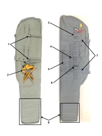
97 97
98 MODULAR AIRBORNE WEAPONS CASE 1. POUCH ATTACHMENT LADDER SYSTEM WEBBING 2. LOWER TIE DOWN STRAP STOW POCKET 3. PILE TAPE 4. RIFLE BUTT STOW POCKET 5. CLOSING FLAP 6. INTERNAL PADDED DIVIDER 7. NOSE CONE SECURING STRAPS 8. SLIDE FASTENER AND TABBED THONG 9. INTERNAL POCKET 98
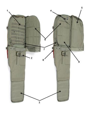
99 99
100 100
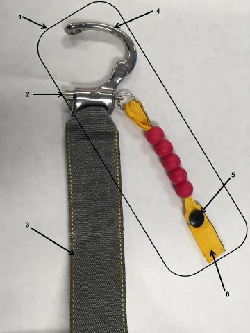
101 101
102 102
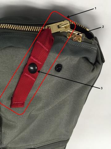
103 103
104 104
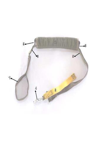
105 105
106 106
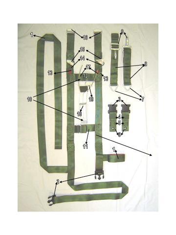
107 107
108 108
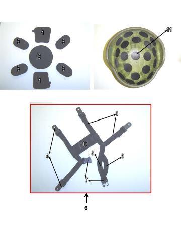
109 109
110 THIS PAGE INTENTIONALLY LEFT BLANK 110

111 111
112 5 FOOT UNIVERSAL STATIC LINE EXTENSION 1. 5 FOOT UNIVERSAL STATIC LINE EXTENSION 2. COTTON BUFFER 112
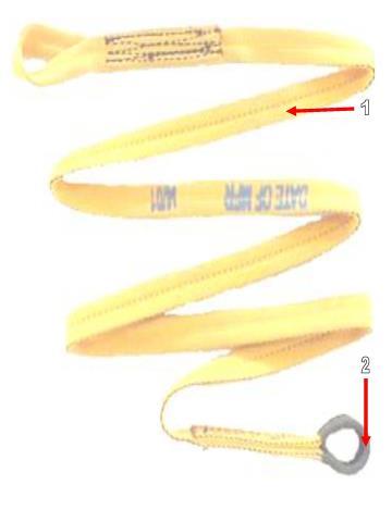
113 113
114 114
115 115
116 116
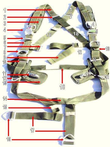
117 117

118 118
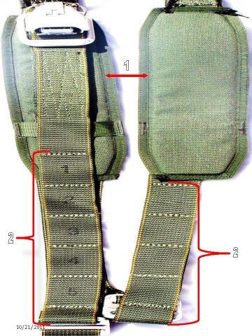
119 119
120 120
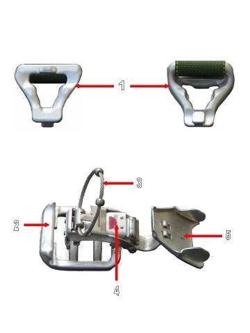
121 121
122 122
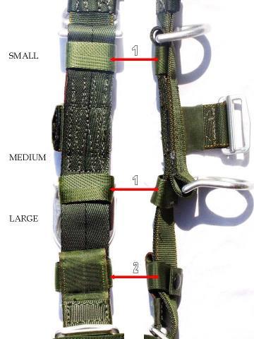
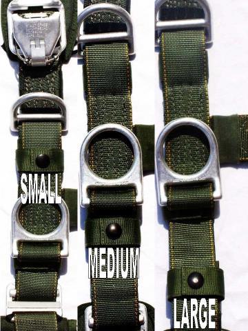
123 123
124 124
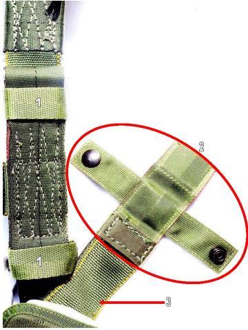
125 125
126 126
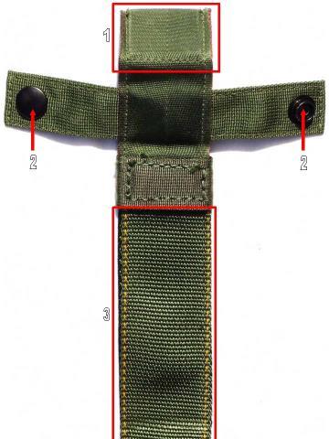
127 127
128 128
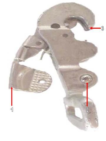
129 129
130 130
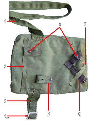
131 131
132 132
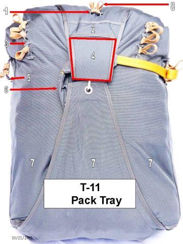
133 133
134 134
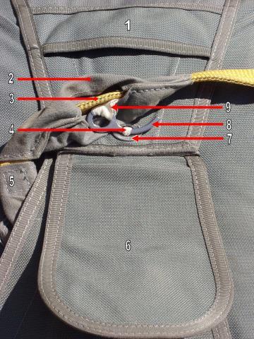
135 135
136 136
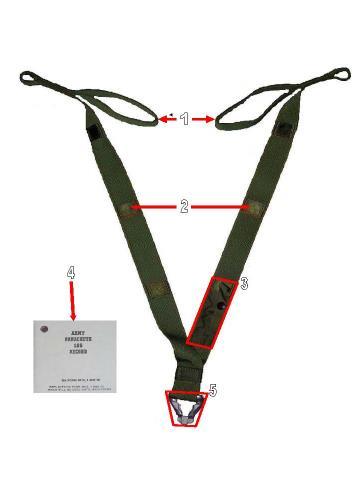
137 137
138 138
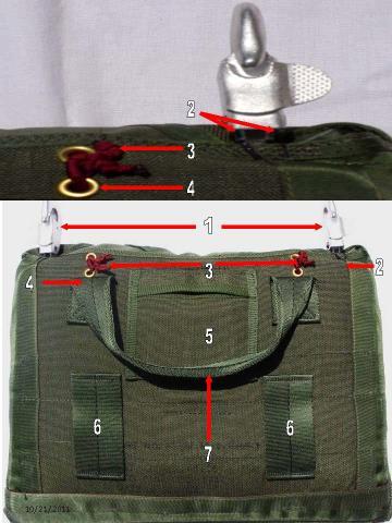
139 139
140 140
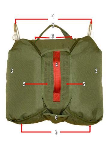
141 141
142 142
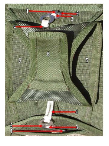
143 143
144 144
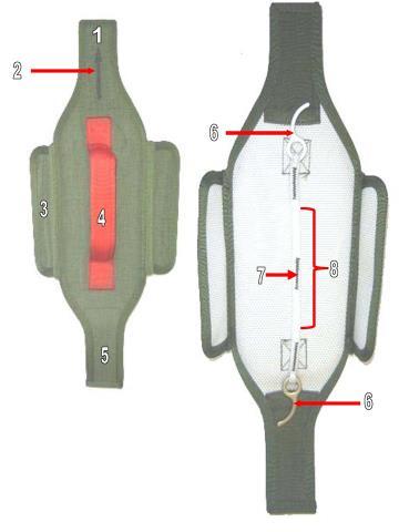
145 145
PRE- JUMP TRAINING (T-11)
") THE FIVE POINTS OF PERFORMANCE: PRE- JUMP TRAINING (T-11) The first point of performance is PROPER EXIT, CHECK BODY POSITION, AND COUNT. JUMPERS HIT IT. Upon exiting the aircraft, snap into a good tight
THE FIVE POINTS OF PERFORMANCE: PRE- JUMP TRAINING (T-11) The first point of performance is PROPER EXIT, CHECK BODY POSITION, AND COUNT. JUMPERS HIT IT. Upon exiting the aircraft, snap into a good tight
PRE-JUMP FOR FORT BRAGG UNITS OCTOBER 2016
 The first items I will discuss are the five points of performance. The first point of performance is proper exit, check body position, and count. Jumpers hit it. Upon exiting the aircraft, snap into a
PRE- JUMP TRAINING (T-11 Heavy)
") THE FIVE POINTS OF PERFORMANCE: PRE- JUMP TRAINING (T-11 Heavy) The first point of performance is PROPER EXIT, CHECK BODY POSITION, AND COUNT. JUMPERS HIT IT. Upon exiting the aircraft, snap into a good
THE FIVE POINTS OF PERFORMANCE: PRE- JUMP TRAINING (T-11 Heavy) The first point of performance is PROPER EXIT, CHECK BODY POSITION, AND COUNT. JUMPERS HIT IT. Upon exiting the aircraft, snap into a good
JMPI for the MODULAR AIRBORNE WEAPONS CASE (MAWC)
") JMPI for the MODULAR AIRBORNE WEAPONS CASE (MAWC) The Modular Airborne Weapons Case (MAWC) will be inspected in its entirety prior to inspecting the Reserve Parachute. The inspection of the MAWC begins
JMPI for the MODULAR AIRBORNE WEAPONS CASE (MAWC) The Modular Airborne Weapons Case (MAWC) will be inspected in its entirety prior to inspecting the Reserve Parachute. The inspection of the MAWC begins
MC6/T 11 ATPS Donning. Step by step instructions
 MC6/T 11 ATPS Donning Step by step instructions TRANSITION: Prior to your practical exercise you must first understand how to properly size the parachute harness. The parachute harness must be sized prior
Butler Tactical Parachute Systems, LLC
 Butler Tactical Parachute Systems, LLC A division of Butler Parachute Systems Group, Inc. TT-600 TETHERED TANDEM BUNDLE DELIVERY SYSTEM PACKING MANUAL (REVISION A ) Page 1 of 62 INTRODUCTION This manual
Butler Parachute Systems, Inc
 Butler Parachute Systems, Inc A division of Butler Parachute Systems Group, Inc. TT-600 GEN 1 & 2 TETHERED TANDEM BUNDLE DELIVERY SYSTEM ASSEMBLY MANUAL 1 JUN 2010 INTRODUCTION This manual contains all
TECHNICAL MANUAL OPERATOR'S MANUAL FOR
 TECHNICAL MANUAL OPERATOR'S MANUAL FOR PARACHUTE PERSONNEL, TYPES 28-FOOT-DIAMETER BACK, 28-FOOT-DIAMETER CHEST, NB-8 BACK AND MARTIN-BAKER EJECTION SEAT HARNESSES This manual supersedes TM 10-1670-213-10,
MAN-032 Rev 0. Performance Designs Zero Packing Manual
 Performance Designs Zero Packing Manual Packing your PD ZERO Before you begin packing, please first review PD s Ram-Air Parachute Owner s Manual. Pay careful attention to the warning/ discussion on pages
Emergency Bailout Procedures for Pilots Presented by Allen Silver Sean Tucker 5April 2006
 Emergency Bailout Procedures for Pilots Presented by Allen Silver Sean Tucker 5April 2006 Allen services all types of emergency parachutes and specializes in bailout training. He has been serving aerobatic
K-9 JUMP DOG, TRAINING KIT, AND JUMP PACKAGE
 K-9 JUMP DOG, TRAINING KIT, AND JUMP PACKAGE CPS-143-158 (K9 JUMP MANNEQUIN) COLOR: BLACK CPS-154-468 (K9 TRAINING KIT) COLOR: BLACK CPS-152-457 (K9 JUMP PACKAGE) COLOR: BLACK K9-specific jump training
FM /MCRP P/NAVSEA SS400-AD-MMO-010/ TO 13C
 Rigging Zodiac F470U Boat in A- Cargo Bag. Fold the boat up onto the box so that the second floor D-ring is nearly even with the front edge of the box. Make sure the floor slats lie flat and the inflation
CHAPTER 2 GROUND RAPPELLING
 CHAPTER 2 GROUND RAPPELLING Ground rappelling is a technique that allows soldiers to negotiate mountains and cliffs safely and rapidly. Before rappellers participate in mountain and cliff rappelling they
MC-3 MILITARY FREE-FALL SYSTEM
 APPENDIX A MC-3 MILITARY FREE-FALL SYSTEM Although the MC-3 MFF system is still available in the procurement system, user units should make the transition to the RAPS to ensure joint interoperbility and
RAPPEL MASTER COURSE
 WARRIOR TRAINING CENTER RAPPEL MASTER COURSE RMPI HANDOUT WHEN THE WILL IS STRONG, EVERYTHING IS EASY FY2015 v 1.2 2 RAPPEL MASTER PERSONNEL INSPECTION Rappel Master Personnel Inspection (RMPI) is performed
On the Go Swing System Instruction Manual
 On the Go Swing System Instruction Manual WARNING READ ENTIRE MANUAL BEFORE USE. THIS SWING IS NOT A TOY. THIS SWING IS ONLY TO BE USED BY TRAINED PERSONNEL, SUCH AS AN OCCUPATIONAL THERAPIST, PHYSICAL
Tactical Flotation Support System (TFSS) User s Manual
 User s Manual") Tactical Flotation Support System (TFSS) User s Manual Aerial Machine and Tool Corp. 4298 JEB Stuart Hwy Meadows of Dan, VA 24120 www.aerialmachineandtool.com Phone: 276-952-2006 FAX: 276-952-2231 Table
Tactical Flotation Support System (TFSS) User s Manual Aerial Machine and Tool Corp. 4298 JEB Stuart Hwy Meadows of Dan, VA 24120 www.aerialmachineandtool.com Phone: 276-952-2006 FAX: 276-952-2231 Table
Wing assemblyfinal Master 4/29/04 11:20 PM Page 1. Issued January 1, Sabre Aircraft. Assembly Manual. Sabre 16ss Wing
 Wing assemblyfinal Master 4/29/04 11:20 PM Page 1 Issued January 1, 2002 Sabre Aircraft Assembly Manual Sabre 16ss Wing Wing assemblyfinal Master 4/29/04 11:20 PM Page 2 1. 2. 1. Unzip the cover and remove
Chesley H. Judy Safety Award free download at no later than February 15 Participating Drop Zones Contact your local
 he ninth annual USPA Safety Day will take place Saturday, March 11. Patti Chernis originally developed the idea of Safety Day and brought it to USPA in 1996. USPA implemented the first Safety Day in March
On the Go Swing System Instruction Manual
 On the Go Swing System Instruction Manual WARNING READ ENTIRE MANUAL BEFORE USE. THIS SWING IS NOT A TOY. THIS SWING IS ONLY TO BE USED UNDER ADULT SUPERVISION. CONSULT WITH A CHILD S THERAPIST ON HOW
Surface Rescue Swimmer School. Primary Rescue Devices and Procedures LT 4.3
 Surface Rescue Swimmer School Primary Rescue Devices and Procedures LT 4.3 2005 1 ENABLING OBJECTIVES Explain the functional operation of the following Rescue Devices per NTTP 3-50.1: 3 Double Rescue Hook
Fall Protection PPE Inspection
 Fall Protection PPE Inspection Fall Protection Equipment All Personal Protective Equipment (PPE) shall be inspected when issued, prior to each use and on a regular basis If found defective it should be
EXIT WINDOW USING PERSONAL SAFETY SYSTEM (PSS) WITH REMOTE ANCHOR
 WITH REMOTE ANCHOR") October 1, 2007 EXIT WINDOW USING PERSONAL SAFETY SYSTEM (PSS) WITH REMOTE ANCHOR 1. EQUIPMENT Personal Harness and Personal Safety System. 2. OBJECTIVE To enable a firefighter to remove themselves from
October 1, 2007 EXIT WINDOW USING PERSONAL SAFETY SYSTEM (PSS) WITH REMOTE ANCHOR 1. EQUIPMENT Personal Harness and Personal Safety System. 2. OBJECTIVE To enable a firefighter to remove themselves from
NATIONAL SMOKEJUMPER TRAINING GUIDE USFS Chapter 6 LANDING TECHNIQUES
 Chapter 6 LANDING TECHNIQUES 1 LESSON PLAN OUTLINE PROGRAM: SMOKEJUMPER LESSON: LANDING TECHNIQUES OBJECTIVES: Trainees shall perform correct parachute landing falls (PLF) according to approved techniques
OUTLINE SHEET Demonstrate procedures for parachute disentanglement for the Quick Fitting and Integrated Torso Harnesses.
 OUTLINE SHEET 4.3-1 PARACHUTE DISENTANGLEMENT PAGE 1 of 11 INTRODUCTION Aviation personnel, who have bailed out or ejected from their aircraft, may be entangled in their parachute. This presents the rescue
Revisions to the Regulations for Agility Trials
 Revisions to the Regulations for Agility Trials Effective January 2, 2018 Equipment changes may be done prior to January 2, 2018, but must be completed by January 2, 2018 This insert is issued as a supplement
User Instructions 1790 Rail Anchor
 User Instructions 1790 Rail Anchor This document is intended to meet the Manufacturer s Instruction requirements as stated by ANSI Z359.1, and should be used as part of an employee training program as
Aviation Rescue Swimmer School
 Aviation Rescue Swimmer School Primary Rescue Devices and Procedures LT 4.3 JANUARY 2004 1 ENABLING OBJECTIVES Explain the functional operation of the following Rescue Devices per NWP 3-50.1: 3 Double
User Instructions 1789 Parapet Wall Anchor
 User Instructions 1789 Parapet Wall Anchor This manual is intended to meet the Manufacturer Instructions as required by ANSI Z359.1 and should be used as part of an employee training program as required
Objectives (1 of 3) List at least two types of materials and designs used in rope manufacture. Define and describe the following: Dynamic rope Static
 List at least two types of materials and designs used in rope manufacture. Define and describe the following: Dynamic rope Static") Chapter 16 Rescue Objectives (1 of 3) List at least two types of materials and designs used in rope manufacture. Define and describe the following: Dynamic rope Static rope Webbing List at least five rules
Chapter 16 Rescue Objectives (1 of 3) List at least two types of materials and designs used in rope manufacture. Define and describe the following: Dynamic rope Static rope Webbing List at least five rules
Fall Protection Checklist. Guardrail System
 Fall Protection Checklist Location/Department: Date of Inspection: Inspectors: Corrective Actions: Work order/memos were issued: Yes No Date issued: In accordance with the MIOSHA and OSHA standards the
Category D Training Aid. All training to be conducted by instructors of the:
 Category D Training Aid All training to be conducted by instructors of the: Visualization: Mind Over Body Did you know that done properly, visualizing what you re about to do can be as effective as practicing
Army Mountain Warfare School Ethan Allen Firing Range Jericho, VT Military Mountaineer Course Knot Guide
 Army Mountain Warfare School Ethan Allen Firing Range Jericho, VT 05465-9796 Military Mountaineer Course Knot Guide 2 - Basic Knot Tying 071E9002 INTRODUCTION: There are many knots used in mountaineering.
II-28 STOKES BASKET OPERATIONS
 1 II-28 STOKES BASKET OPERATIONS Anchor Slings- (2) high strength nylon webbing straps with D-rings on both ends used to set an anchor. Max working load of 10,000 lbs. Bight- Element of knot formed by
User Instruction Manual Fixed Beam Anchor
 User Instruction Manual Fixed Beam Anchor This manual is intended to meet the Manufacturer s Instructions as required by ANSI Z359.1 and ANSI A10.14, and should be used as part of an employee training
OUTLINE SHEET 4.3 PRIMARY RESCUE DEVICES AND PROCEDURES Explain the functional operation of the following Rescue Devices per NTTP 3-50.
 ENABLING OBJECTIVES: 3.28 Explain the functional operation of the following Rescue Devices per NTTP 3-50.1: a. Double Rescue Hook b. Modified Rescue Strop c. Rescue Litter/SAR MEDEVAC Litter, Trail Line
IMPORTANT: If you have questions on the use, care, application, or suitability of this equipment contact DBI/SALA.
 Model Numbers: (See back cover for model numbers) User Instruction Manual Body Belts for Personal Restraint Applications This manual ishould be used as part of an employee training program as required
ARNG WARRIOR TRAINING CENTER PATHFINDER COURSE FORT BENNING, GEORGIA 31905
 ARNG WARRIOR TRAINING CENTER PATHFINDER COURSE FORT BENNING, GEORGIA 31905 071A0204 05 February 2014 HLZ SUMMARY SHEET: INSTRUCTIONAL INTENT: To enable the Pathfinder student to plan for and operate day
You may order this publication from WCB Publications and Videos, Please quote ordering number BK60.
 The following material is the property of the Workers Compensation Board of British Columbia and may not be reproduced by those outside of B.C. For those within British Columbia, this material may only
LESSON PLAN JANUARY Terminal Objective: Partially supported by this lesson topic: COURSE TITLE: Rescue Swimmer Refresher Course Q
 LESSON PLAN JANUARY 2004 COURSE TITLE: Rescue Swimmer Refresher Course Q-050-0604 CLASSIFICATION: LESSON PLAN NUMBER: 3.4 Unclassified LESSON TOPIC: Navy and Air Force Aircrew Survival Equipment, Harnesses
User Instruction Manual Fixed Beam Anchor
 Instructions for the following series products: FIXED BEAM ANCHOR Model Numbers: The Ultimate in Fall Protection 2108406 2108407 2108408 2108409 2108410 2108411 User Instruction Manual Fixed Beam Anchor
SURVIVOR SERIES AIRCREW FLOTATION VEST PACKING INSTRUCTIONS
 SURVIVOR SERIES AIRCREW FLOTATION VEST PACKING INSTRUCTIONS Applicable Part Numbers: AMTC-V1126-BL SURVIVOR LITE AMTC-V1130-BL SURVIVOR (With Extraction Harness) Capewell Aerial Systems LLC Connecticut
RIGGERS SAFETY SAFETY IS IN THE DETAILS FULL LINE CATALOG
 RIGGERS SAFETY SAFETY IS IN THE DETAILS FULL LINE CATALOG Riggers Safety is a California-based manufacturer of Personal Fall Arrest Systems (PFAS) and Fall Prevention Products. Our automated manufacturing
User Instruction Manual For Davit Rescue System
 Instructions for the following series products: Rescue Davit System Model numbers 8004000 and 8302500 User Instruction Manual For Davit Rescue System This manual should be used as part of an employee training
Mount the actuator in the bracket provided and install a 24-foot EFTC cable to the actuator.
 . Mount the actuator in the bracket provided and install a 4-foot EFTC cable to the actuator. Route the cable through left stanchions,, and 4. Be sure that the cable does not contact any spring or push
INSTRUCTION MANUAL NO 719 PARACHUTE ASSEMBLY GQ SECURITY TYPE 850 MK 2 MRI GQ 1284 GENERAL INFORMATION MAINTENANCE AND PACKING INSTRUCTIONS
 INSTRUCTION MANUAL NO 719 PARACHUTE ASSEMBLY GQ SECURITY TYPE 850 MK 2 MRI GQ 1284 GENERAL INFORMATION MAINTENANCE AND PACKING INSTRUCTIONS ISSUE 2 DECEMBER 2000 STATEMENT OF INITIAL CERTIFICATION This
Inspection & Maintenance
 PERSONAL FALL ARREST EQUIPMENT Inspection & Maintenance This article addresses the requirements of OSHA1926.502(d)(21), which states that personal fall arrest systems shall be inspected prior to each use
Wingsuit Owners Manual
 Tony Uragallo flying the Apache, photo Jeff Nebelkopf Wingsuit Owners Manual Version 1 - April 2012 Dear Tony Suit Customer Thank you for your recent wingsuit purchase. Please take a few minutes to read
Contents. Technical Data. Permittable load. Suspension height. 45 cm, incl. carabiner. Speed System. Weight (without rescue system) 7 kg (size L)
 7 kg (size L)") Manual/Service 13 Contents Technical Data Fundamentals of the RANGE Technical Data Intended Use Permittable load Suspension height Glider Harness 120 kg 45 cm, incl. carabiner Speed System Rescue System
Manual/Service 13 Contents Technical Data Fundamentals of the RANGE Technical Data Intended Use Permittable load Suspension height Glider Harness 120 kg 45 cm, incl. carabiner Speed System Rescue System
Tower Accessories & Hardware
 Safety-Climb Cable System for Climbing Ladder These Safety-Climb Cable products clamp to climbing ladder rungs up to 1-1/4" (32 mm) in diameter. The products meet or exceed OSH requirements for climbing
1.2 LIMITATIONS: Consider the following application limitations before using this equipment:
 User Instruction Manual Standing Seam Roof Anchor This manual is intended to meet the Manufacturer s Instructions, and should be used as part of an employee training program as required by OSHA. Figure
2990 Lorne Scots Royal Canadian Army Cadet Corps Rifle Drill
 2990 Lorne Scots Royal Canadian Army Cadet Corps Rifle Drill Page 1 of 27 TABLE OF CONTENTS PARA ITEM PAGE Section 1 BASIC RIFLE DRILL 1.1 INTRODUCTION 3 1.2 ATTENTION 5 1.3 STAND AT EASE FROM ATTENTION
RIGGERS SAFETY SAFETY IS IN THE DETAILS FULL LINE CATALOG
 RIGGERS SAFETY SAFETY IS IN THE DETAILS FULL LINE CATALOG Riggers Safety is a California-based manufacturer of Personal Fall Arrest Systems (PFAS) and Fall Prevention Products. Our automated manufacturing
IIHF GOALKEEPER EQUIPMENT MEASUREMENT STANDARDS
 2009-2010 IIHF GOALKEEPER EQUIPMENT MEASUREMENT STANDARDS PREAMBLE These equipment standards are written in the spirit of fair play and are a supplement to the IIHF Rule Book. If at any time the IIHF feels
Wilson County Emergency Management Agency 110 Oak Street Lebanon, Tennessee 37087
 SOG Name: High Angle & Rope Rescue SOG Number: 403.09 Effective Date: February 2, 2015 Approved: Joey Cooper, Director Reviewed: Scope The purpose of this procedure is to establish guidelines for conducting
NATIONAL (NATO) STOCK NUMBER: NSN
 STOCK NUMBER: NSN") THE SKED RESCUE SYSTEM NATIONAL (NATO) STOCK NUMBER: NSN 6530-01-260-1227 FLOTATION INSTRUCTIONS Please Post In Your Training Area SKED RAPID DEPLOYMENT FLOATATION SYSTEM Thank you for your purchase of
THE SKED RESCUE SYSTEM NATIONAL (NATO) STOCK NUMBER: NSN 6530-01-260-1227 FLOTATION INSTRUCTIONS Please Post In Your Training Area SKED RAPID DEPLOYMENT FLOATATION SYSTEM Thank you for your purchase of
IIHF GOALTENDER EQUIPMENT MEASUREMENT STANDARDS
 2017-2018 IIHF GOALTENDER EQUIPMENT MEASUREMENT STANDARDS PREAMBLE These equipment standards are written in the spirit of fair play and are a supplement to the IIHF Rule Book. If at any time the IIHF feels
Kratos Safety FA FA FA FA POINT LUXURY FULL BODY HARNESS
 FA 10 202 00 3 FA 10 201 00 2 Model: FA 10 202 00 EN 358:2000 EN 813:2008 5 POINT LUXURY FULL BODY HARNESS Work positioning belt with 2 D rings. Waist level D ring for rope access. Quick connect buckles.
CBP LPU- 40 Flotation Collar User s Manual
 CBP LPU- 40 Flotation Collar User s Manual January 2015 Capewell Aerial Systems LLC 4298 JEB Stuart Hwy Meadows of Dan, VA 24120 www.aerialmachineandtool.com Phone: 276-952-2006 FAX: 276-952-2231 Table
CHAPTER 3 HELICOPTER RAPPELLING
 CHAPTER 3 HELICOPTER RAPPELLING Helicopter rappelling can provide a means of quick insertion with or without an LZ. Section I. PERSONNEL The personnel required for helicopter rappelling are the rappel
2018 Skydiver s Information Manual Summary of Changes
 Table of Contents SECTION 2 BASIC SAFETY REQUIREMENTS AND WAIVERS 3 2-1 BASIC SAFETY REQUIREMENTS 3 C. MEDICAL REQUIREMENTS 3 E. MEMBERSHIP 3 F. ALCOHOL AND DRUGS 3 G. STUDENT SKYDIVERS 3 H. WINDS [S]
SADDLES FOR ARBORISTS USE INSTRUCTIONS / WARNINGS
 SADDLES FOR ARBORISTS USE INSTRUCTIONS / WARNINGS All Arborist Saddles manufactured by Buckingham Mfg. Co. are made from the finest quality components. Buckingham offers a wide selection of Arborist Saddle
LOAD HUGGER CARGO CONTROL
 Hugger BASICS Lift-All Hugger cargo control and load securement products are of the highest quality. They offer the van and flatbed operator a wide variety of options to meet Department of Transportation
Technical Data. Flying with the range2. Maintenance and Repair
 Manual/Service 1 Contents Technical Data Fundamentals of the range2 Speed System Rescue System Rescue System Installation adjustment Possibilities Cross Bracing Ballast Container Pockets Towing Operation
BALLISTIC OPTICAL ARMOR (BOA ) GOGGLE
 GOGGLE") USE AND CARE INSTRUCTIONS BALLISTIC OPTICAL ARMOR (BOA ) GOGGLE 2005 GENTEX Corporation Description............................................. 1 Standard Strap Configurations..................................
USE AND CARE INSTRUCTIONS BALLISTIC OPTICAL ARMOR (BOA ) GOGGLE 2005 GENTEX Corporation Description............................................. 1 Standard Strap Configurations..................................
Figure 1 - Snap Hooks and Carabiners PART NUMBER MANUFACTURER S ID YEAR OF MANUFACTURE PART NUMBER MANUFACTURER S ID YEAR OF MANUFACTURE
 Instructions for the following series products: SNAP HOOKS AND CARABINERS (See back page for specific model numbers.) User Instruction Manual Snap Hooks and Carabiners This manual is intended to meet the
Usage and Care Instructions
 SUPERSTAR Student Transportation Add-On Restraint Usage and Care Instructions SUPERSTAR 25-90 lbs. (11.3-40.8 kg) 52 in. (132 cm) tall or less at least 2 years of age *927360* Table Of Contents Store this
ASSEMBLY MANUAL HOBIE CATSY
 ASSEMBLY MANUAL HOBIE CATSY HOBIE CAT EUROPE ZI Toulon Est, BP 50 8078 Toulon cedex 9, France Tel : + (0)9 08 78 78 - Fax : + (0)9 08 99 Email : hobiecat@hobie-cat.net - http://www.hobie-cat.net ASSEMBLY
UNITED STATES MARINE CORPS WEAPONS TRAINING BATTALION MARINE CORPS COMBAT DEVELOPMENT COMMAND QUANTICO, VIRGINIA
 UNITED STATES MARINE CORPS WEAPONS TRAINING BATTALION MARINE CORPS COMBAT DEVELOPMENT COMMAND QUANTICO, VIRGINIA 22134-5040 DETAILED INSTRUCTOR GUIDE LESSON TITLE RIFLE SITTING POSITION COURSE TITLE ANNUAL
THE AMERICAN BARN DOOR KITE
 THE AMERICAN BARN DOOR KITE Oregon Kitemaker s Retreat January 2007 Rod Beamguard 4104 NW 112 th Way Vancouver, WA 98685-3578 (360) 574-8050 home (360) 750-9833 office kytfevr@wa-net.com PLANFORM BARN
Falcon 3 145, 170, 195 and Tandem Owner / Service Manual
 Falcon 3 145, 170, 195 and Tandem Owner / Service Manual January 2007 - Second Edition Removing The Sail From The Airframe And Short Packing The Glider Many maintenance and repair procedures will require
THOR 10 HAMMER CAGE INSTRUCTIONS
 75 " 7m 78 4" m 6" 8.8m 45 ".70m 4.9deg 6 4" 6m 44 4".67m 75 " 7m 9 4" 0m 44".m 497 4".64m The 70, Thor Hammer Cage, consists of four heavy duty aluminum net poles. The unique pole structure reduces the
TENNESSEE COMMISSION ON FIRE FIGHTING
 TENNESSEE COMMISSION ON FIRE FIGHTING FIRE FIGHTER I PRACTICAL EVALUATION 2002 Edition of NFPA 1001 Standard Department of State, Authorization No., 500 copies, April 2006. This public document was promulgated
LPU- 40 Flotation Collar
 105 Nutmeg Road South South Windsor, CT 06074 sales@capewell.com P: 860.610.0700 www.capewell.com LPU- 40 Flotation Collar User s Manual List of Revisions or Amendments Date Revision or Amendment 12 January
EUROBUNGY-TRAMPOLINE
 EUROBUNGY-TRAMPOLINE Set-up instructions of the new model 2004-2010 Photos are taken with the long and short Trailer WARNING for EUROBUNGIES without hydraulic rams There is a potential risk that a pole
Parachutage Hardware Onderdelenlijst
 Parachutage Hardware Onderdelenlijst Alle hardware items voor Parachute gebruik werden opgesomd op deze pagina. Graag beantwoorden we uw specifieke vragen. Contacteer ons info@jera-aae.com Tel. 056 50
Installation Instructions
 116-3027, 116-3017 X-Pando Adjustable Steel Protector Installation Instructions 1404 N. Marshall Ave. El Cajon CA. 92020 For technical support call us at (800) 368-3075 NB 6/28/10 607-0112 Step 1. Mounting
Stand-N-Fish FULL DETAIL INSTALLATION INSTRUCTIONS
 1 Stand-N-Fish FULL DETAIL INSTALLATION INSTRUCTIONS Thank you for purchasing the incredible new Stand-N-Fish Kayak Fishing System. Once installed on your kayak the Stand-N-Fish will take your kayak fishing
CHAPTER 4 ADVANCED GROUND-FIGHTING TECHNIQUES
 (FM 21-150) CHAPTER 4 ADVANCED GROUND-FIGHTING TECHNIQUES After achieving an understanding of the basics of ground fighting, other elements of fighting on the ground are added. These techniques, however,
SECTION V. Terminology: Bight: Double Bight: Loop: Turn: Round Turn: Half Hitch: Girth Hitch: Running End: Standing End:
 SECTION V. Terminology: When using ropes, understanding basic terminology is important. The terms explained in this section are the most commonly used in military mountaineering. (a) Bight: A bight of
Restraint Systems for Disabled Persons
 TEST METHOD 213.3 Restraint Systems for Disabled Persons Revised: Issued : May 2012R June 1, 1987 (Ce document est aussi disponible en français) Table of Contents 1. Introduction... 1 2. Test Devices to
RIDE Inc. Rigscape Service Rig Procedures
 2016 RIDE Inc. Rigscape Service Rig Procedures Special Instructions/Conditions of Use Reading user procedure manual prior to use is essential Only persons that have been deemed competent in the operation
WI GS Harness/Container System
 WI GS Harness/Container System OW ERS MA UAL Sunrise Manufacturing International, Inc./SMI Inc. 6520 Fort King Road Zephyrhills, Florida 33542 tel: +1 813 780 7369 fax: +1 813 788 2799 sales@skydivewing.com
PRO BANDS TRAINING GUIDE
 PRO BANDS TRAINING GUIDE Thank you for choosing SKLZ Pro Bands. We are dedicated to providing you with the best tools and instruction possible to help you unleash your athletic potential. If there is anything
Key Terms. balance barrel bolt butt hand guard muzzle port arms sling stacking swivel stock trail arms trigger guard
 Lesson 7 Stationary Movements with the M-1 Rifle Chapter 5 Key Terms balance barrel bolt butt hand guard muzzle port arms sling stacking swivel stock trail arms trigger guard What You Will Learn to Do
A-License Information Packet
 A-License Information Packet 1. Objective The objective of this packet is to review several parts of the United States Parachute Association (USPA) A License Proficiency Card and to learn additional aspects
OPERATION, INSTALLATION AND WARNING RELATING TO THE SUP'AIR "PERMANENT AIRBAG" PROTECTION SYSTEM BEFORE FLYING, CHECK: WARNING
 Thank you for choosing one of our products; we hope you will have long, pleasant flights in your harness. When we design our products, we pay particular attention to all aspects of comfort, durability
Installation Instructions - Steel 4 Spring Arm Kits , , , ,
 Installation Instructions - Steel Spring Arm Kits 50-0709, 50-079, 50-0750, 50-075, 50-078 GR 8// 07-00 0 N. Marshall Ave. El Cajon CA. 900 For technical support call us at (800) 8-075 Step. Determining
9-Cell MAIN CANOPIES
 4357 D PARK DRIVE NORCROSS, GA 30093 USA Phone (770)-279-7733 FAX (770)-279-7729 MAIN CANOPY OWNER'S MANUAL and PACKING INSTRUCTIONS for all 9-Cell MAIN CANOPIES March 2007 1. TRAINING AND/OR EXPERIENCE
MSA Cairns FIRE HELMET PRODUCT SPECIFICATION
 MSA Cairns FIRE HELMET PRODUCT SPECIFICATION PRODUCT TYPE: Structural Firefighting Helmet PRODUCT MODEL(S): PURPOSE: To supply a uniform, standard product specification for a thermoplastic structural fire
PN BuckCat Series Saddles Instructions/Warnings
 PN 16905 BuckCat Series Saddles Instructions/Warnings The BuckCat is a light weight saddle developed for the professional arborist. It is fully adjustable at the sides, waist and legs to provide ease of
Aerodyne Flight Recommendations
 Aerodyne Flight Recommendations In this essay we present you with some recommendations, in order to assist you in learning more about your canopy, and how to use it in a better way, so that you can become
Lumbar Pack Safety System: Webbing
 Lumbar Pack Safety System: Webbing Black Sunday New York City: January 23, 2005 o Bronx Box 3-3 2997: (6) Firefighters forced to bail out of a 4 th story window; (3) firefighters killed, (3) firefighters
8MAY15 US RACK, Inc Falcon Drive, Madera, CA
 8MAY15 US RACK, Inc. - 2850 Falcon Drive, Madera, CA 93637-559-661-3050 INSTRUCTIONS for Bedrail-mounted MOTORCYCLE RACK, Model 2001-4TRA WARNING: Do NOT attempt to install or use this rack without following
Instructions for the following series products:
 Instructions for the following series products: Full Body Harnesses (See back pages for specific model numbers.) User Instruction Manual Full Body Harness This manual is intended to meet the Manufacturer
ExtendAire TM II. Intermediate Pressure Accessory Kit USER INSTRUCTIONS
 ExtendAire TM II Intermediate Pressure Accessory Kit USER INSTRUCTIONS THIS MANUAL MUST BE CAREFULLY READ AND FOLLOWED BY ALL PERSONS WHO HAVE OR WILL HAVE THE RESPONSIBILITY FOR USING OR SERVICING THIS
Performance Examination 4100 Sub JAC Handbook
 TOPIC: CATEGORY: JAC PERFORMANCE EXAM 24 Extension Ladder POINTS POSSIBLE: 100 TIME ALLOWED: 6 Minutes BEHAVIORAL OBJECTIVE: Condition: Behavior: Standard: An engine with a MMR SCBA mounted in a breathing
HEADQUARTERS DEPARTMENT OF THE ARMY UNITED STATES MARINE CORPS DEPARTMENT OF THE NAVY DEPARTMENT OF THE AIR FORCE
 FM 4-20.102 MCRP 4-11.3J NAVSEA SS400-AB-MMO-010 TO 13C7-1-5 AIRDROP OF SUPPLIES AND EQUIPMENT: RIGGING AIRDROP PLATFORMS JUNE 2006 DISTRIBUTION RESTRICTION. Approved for public release; distribution is
L-23 Super Blanik Rigging (assembly/disassembly) Guide Maj Carl Kerns
 Guide Maj Carl Kerns") L-23 Super Blanik Rigging (assembly/disassembly) Guide Maj Carl Kerns The L-23 Blanik is a difficult Sailplane to rig (assemble). The wings are heavy and are secured via a single
L-23 Super Blanik Rigging (assembly/disassembly) Guide Maj Carl Kerns The L-23 Blanik is a difficult Sailplane to rig (assemble). The wings are heavy and are secured via a single
Level 1 Vault STRETCH JUMP ONTO A RAISED MAT SURFACE (A MINIMUM OF 16 ) AND THEN HANDSTAND FALL TO STRAIGHT LYING POSITION ON THE BACK
 AND THEN HANDSTAND FALL TO STRAIGHT LYING POSITION ON THE BACK") Level 1 Vault The gymnast may perform the vault (both skills) two times. Each phase of the vault is worth 5.0 points with the score of each phase added together. The highest total score of the two vaults
Level 1 Vault The gymnast may perform the vault (both skills) two times. Each phase of the vault is worth 5.0 points with the score of each phase added together. The highest total score of the two vaults