Safety Requirement Specification
|
|
|
- Martin Bridges
- 6 years ago
- Views:
Transcription

1 Safety Requirement Specification An Overview of the Safety Requirement Specification Process in IEC Budapest University of Technology and Economics Department of Measurement and Information Systems


2 Standards for Safety-Related Systems Domain Generic Process Vehicle Aircraft Railway Space Certification Development process Safety Analysis/ Assessment IEEE IEC CMMI IEC ISO DO-178C, DO-278A, DO-333 IEC IEC-50128, IEC ECSS 2
3 Functional Safety Concept: Risk Risk based approach for determining the target failure measure o Risk is a measure of the probability and consequence of a specified hazardous event occurring o There is no such thing as Zero Risk A safety-related system both o implements the required safety functions necessary to achieve a safe state for the EUC or to maintain a safe state for the EUC o is intended to achieve the necessary safety integrity for the required safety functions 3
 Utility + Risks")
 Risk reduction Safety")

4 Model of Risk Reduction EUC Control System Equipment Under Control (EUC) Utility + Risks Safety Functions Safety-Related System (Protection System) Risk reduction Safety Functions E/E/PE safety-related systems, other technology safety-related systems, external risk reduction facilities 4
5 Functional Safety Concept: Risk Reduction The Safety Functions (SF) are concerned with risk reduction o There is EUC risk: risk arising from the EUC or its interaction with the EUC control system [EUCCS] o There is a tolerable risk (socially derived) o There is a residual risk: risk remaining after protective measures have been taken Developers must assess o the EUC risk and the tolerable risk to calculate the required safety integrity level (SIL) o the residual risk, which must be as low as reasonably practicable (ALARP) 5

6 Determining the Necessary Risk Reduction Residual risk Tolerable risk EUC risk Necessary risk reduction Actual risk reduction Increasing risk Partial risk covered by other technology safety-related systems Partial risk covered by E/E/PE safety-related systems Partial risk covered by external risk reduction facilities Risk reduction achieved by all safety-related systems and external risk reduction facilities 6
7 Is Airbag Deployment a Safety Function? Safety function: o is intended to achieve or maintain a safe state for the EUC, in respect of a specific hazardous event o is concerned with risk reduction Airbag deployment o Reduces harm reduces risk o Does not return the EUC to a safe state o Risk reduction properties: does not reduce the likelihood (frequency) of any hazardous events that are collisions but reduces the severity (consequences) of those events 7
8 Is the ABS a Safety-Related System? Consider an anti-lock braking system, an ABS o the EUC is the brakes o the EUCCS is the brake activation mechanism, from pedal to brake pads o the SRS is the wheel-rotation sensors and the responsive brakerelease-and-reapply mechanism Functional safety assessment: o the EUC risk is known o similarly the tolerable risk o the required risk reduction can be calculated o this requirement can be transformed into a SIL Then it can be demonstrated that the ABS fulfils the SIL But the ABS is not designated as an SRS (which must always be active) but rather as a functional enhancement which is not formally safety-related 8
9 Safety Requirements Requirements for a safety related system: o Safety function requirements Derived from hazard identification o Safety integrity requirements Relates to the target failure measure of the safety function Derived from risk assessment The required safety integrity of the safety-related systems, must be of such a level so as to ensure that o the failure frequency of the safety-related systems is sufficiently low to prevent the hazardous event frequency exceeding that required to meet the tolerable risk, and/or o the safety-related systems modify the consequences of failure to the extent required to meet the tolerable risk 9
10 Structure of Requirements System requirements specification Safety requirements Non-safety requirements Safety requirements specification Safety functional requirements Safety integrity requirements Hardware (random) failure integrity Systematic failure integrity 10
11 Development of Safety Functions The development of safety functions requires the following steps: o Identify and analyze the risks o Determine the tolerability of each risk o Determine the risk reduction necessary for each intolerable risk o Specify the safety requirements for each risk reduction, including their safety integrity levels (SILs) o Design safety functions to meet the safety requirements o Implement the safety functions o Validate the safety functions 11

12 Life Cycle Activities Related to Safety Functions 12
13 The Risk Assessment Framework The three main stages of Risk Assessment are: 1. Establish the tolerable risk criteria with respect to the frequency (or probability) of the hazardous event and its specific consequences 2. Assess the risks associated with the equipment under control 3. Determine the necessary risk reduction needed to meet the risk acceptance criteria this will determine the Safety Integrity Level of the safetyrelated systems and external risk reduction facilities 13
14 Tolerable Risk Criteria Qualitative criteria use words o such as probable, frequent, unlikely, remote, etc. to describe the likelihood of the hazardous event, and o such as minor, major, catastrophic, etc. to describe the consequences o it is often necessary to introduce quantitative numbers to provide a clear definition of how to interpret these words Quantitative criteria use numbers to describe the likelihood and severity of the event o This can include criteria such as an event having a frequency of less than 10-3 per year, or between 2 and 5 fatalities or serious injuries, etc. 14


15 Consequence Example Risk Bands for Tolerability of Hazards Significant Major Catastrophic Zone 1 Unacceptable Risk Region Zone 3 Tolerable Risk Region Zone 2 Transitional Risk Region Remote Unlikely Possible Probable Frequency (per year) 15
16 Assessing the Frequency of Hazardous Event The risk assessment can be summarized as asking: o How likely is the equipment under control to fail? o If it does fail, what is the outcome? The likelihood or frequency of an event relating to the EUC is determined by o Intrinsic causes such as component failures, software failures, or human error within the EUC o Extrinsic demand (mode of operation): e.g. safety systems only need to function when some failure within the plant occurs Therefore, the assessment must consider both the intrinsic failure rate and the extrinsic demand rate of the equipment under control. 16
17 Assessing the Consequence of Hazardous Event The consequences of an event relating to EUC o can range from the direct effects o to all subsequent events along the escalation path This introduces a dilemma, since o the true consequences of an event can only be determined if the escalation path is assessed through to the end conclusions o however, the escalation path itself may contain other separate functions that are themselves subject to FSA 17


18 Example: Over-Pressurization Protection System EUC failure: rupture of the pipework and significant release Release detected? yes no Isolation and blowdown system worked? yes no Release ignited? Release ignited? yes Further loss of containment and escalation of fire? yes no Firewater system worked? yes no Personnel escaped? no 18
19 Issues with FSA (IEC gives no guidance) In order to accurately determine the EUC risk, the boundary of the analysis has to extend to the end of the event tree o However, if the boundary is extended cover every potential path within the event tree, the analysis will include systems not directly affected by the EUC which themselves may be subject to FSA Another important issue is that the overall safety performance could be improved by achieving a high availability for any element in the escalation path o such as gas detection; isolation and blowdown; protection against ignition; prevention of escalation to adjacent plant; the firewater system; etc. in the previous example 19


20 Example: Thrust Reverser Interlock Thrust reverser deployment in flight almost inevitably leads to loss of control of the aircraft o Catastrophic event On the Boeing B767 aircraft, there is a hydromechanical interlock, which physically prevents the thrust reverse mechanism from operating o on weight on wheels or WoW criterion In May of 1991, a Lauda Air Boeing B767 crashed over Thailand o cause: deployment of the left engine thrust reverser in flight, leading to loss of control o previously unknown failure mode due to disintegration of the rubber-compound seals 20 Deployed clamshell thrust reverser Deployed cascade reverser
21 Risk Reduction: Balancing the Options Example: anti-misting kerosene (AMK) aircraft fuel o idea was to inhibit ignition of the fuel in the case of an aircraft accident The fuel had different physical characteristics from the usual jet fuels o increased risk of engine problems during flight Let us suppose we have two hazards: o H1 is immediate, deadly conflagration of jet fuel in the case of a tank rupture o H2 is all engines cutting out in flight Suppose we eliminate hazard H1 (e.g. by introducing AMK into daily commercial flight operations), and thereby increase the risk associated with H2 o How to reduce the joint risk as far as possible? 21
22 Risk Reduction The EUC risk shall be evaluated, or estimated, for each determined hazardous event Necessary risk reduction: risk reduction to be achieved by o E/E/PE safety-related systems o other technology safety-related systems and o external risk-reduction facilities in order to ensure that the tolerable risk is not exceeded The necessary risk reduction shall be determined for each determined hazardous event. May be determined in a o quantitative and/or o qualitative manner 22


23 Risk and Safety Integrity Concepts Consequence of hazardous event Frequency of hazardous event EUC risk External risk reduction facilities E/E/PE safetyrelated systems Other technology safety-related systems Necessary risk reduction Tolerable risk target EUC and the EUC control system Safety integrity of external risk reduction facilities and safetyrelated systems matched to the necessary risk reduction 23
24 The ALARP Principle The As Low As Reasonably Practicable (ALARP) principle must be used to calculate the required risk reduction o Origins: English law Lord Asquith (1949) Lord Cullen (1989): Piper Alpha oil platform fire investigation Risks are classified as o Acceptable so low that it can for all practical purposes be ignored o Intolerable so high as to be unacceptable in all circumstances o The ALARP region the region between acceptable and intolerable in which the system developer is required to reduce the risk to be as low as reasonably practicable 25
 Negligible risk Tolerable only if further risk reduction is impracticable or if its cost is grossly disproportionate to the")
25 Tolerable Risk and ALARP Intolerable region Risk cannot be justified except in extraordinary circumstances The ALARP or tolerability region (Risk is undertaken only if a benefit is desired) Broadly acceptable region (No need for detailed working to demonstrate ALARP) Negligible risk Tolerable only if further risk reduction is impracticable or if its cost is grossly disproportionate to the improvement gained As the risk is reduced, the less, proportionately, it is necessary to spend to reduce it further to satisfy ALARP. The concept of diminishing proportion is shown by the triangle. It is necessary to maintain assurance that risk remains at this level 26
26 Example: Principles of Radiation Protection The principles of radiation protection are based on the recommendations of the International Commission on Radiological Protection (ICRP) Radiation use must fulfill three basic principles: o Principle of justification The benefits of using radiation must outweigh the drawbacks o Principle of optimization ALARA principle, As Low As Reasonably Achievable Radiation exposure caused by the use of radiation must be kept as low as reasonably achievable o Principle of limitation Exposure of radiation workers and individuals of public must not exceed dose limits 27
27 Taking the ALARP concept into consideration The matching of a consequence with a tolerable frequency can be done through risk classes. Table on the next slide is an example showing four risk classes (I, II, III, IV) for a number of consequences and frequencies. The risks within these risk class definitions are the risks that are present when risk reduction measures have been put in place. The risk classes are as follows: o risk class I is in the unacceptable region; o risk classes II and III are in the ALARP region, risk class II being just inside the ALARP region; o risk class IV is in the broadly acceptable region. For each specific situation, or sector comparable industries, a similar table would be developed taking into account a wide range of social, political and economic factors. 28
28 Example of risk classification of accidents Frequency Consequence Catastrophic Critical Marginal Negligible Frequent I I I II Probable I I II III Occasional I II III II Remote II III III IV Improbable III III IV IV Incredible IV IV IV IV Risk class Class I Class II Class III Class IV Interpretation Intolerable risk Undesirable risk, and tolerable only if risk reduction is impracticable or if the costs are grossly disproportionate to the improvement gained Tolerable risk if the cost of risk reduction would exceed the improvement gained Negligible risk 29
29 Safety Integrity Level (SIL) Each SRS is assigned a SIL o It is the probability that the SRS fulfils its safety function(s) o Represents objectively the reliability of its safety function(s) o Product requirement The SIL is assigned according to the required risk reduction o from EUC risk at least to the tolerable risk A quantitative difference is made between o Continuous-operation (high-demand) functions o Low-demand functions (also known as on-demand functions) Development of an SRS with a designated SIL requires a certain development process o Process requirement 30
30 Safety integrity level (SIL) Safety integrity level (SIL) Low demand mode of operation (Average probability of failure to perform its function on demand) High demand or continuous mode of op. (Probability of a dangerous failure per hour / frequency of dangerous failures, or dangerous failure rate) to < to < to < to < to < to < to < to < 10-5 It is important to note that the failure measures for safety integrity levels 1, 2, 3 and 4 are target failure measures. It is accepted that only with respect to the hardware safety integrity will it be possible to quantify and apply reliability prediction techniques in assessing whether the target failure measures have been met. Qualitative techniques and judgments have to be made with respect to the precautions necessary to meet the target failure measures with respect to the systematic safety integrity. 31
31 Example Methods to Determine the SIL Safety integrity levels are means of satisfying the safety integrity requirements of the safety functions allocated to the safety-related systems The methods used to allocate the safety integrity requirements depend upon whether the necessary risk reduction is specified o in a numerical manner (quantitative method) or o in a qualitative manner Risk Graph Method Hazardous Event Severity Matrix Method 32
32 Quantitative Method to Determine the SIL The key steps in the method are as follows: o determine the tolerable risk from a table such as the ALARP tolerable risk frequencies o determine the EUC risk o determine the necessary risk reduction to meet the tolerable risk o allocate the necessary risk reduction to the E/E/PE safety-related systems, other technology safety-related systems and external risk reduction facilities These steps need to be done for each safety function to be implemented by the E/E/PE SRS 33
 Risk < R t where R t = F t C F p Tolerable risk target EUC and the EUC control system Safety integrity of safety-related protection system matched to the")
33 Safety Integrity Allocation Consequence of hazardous event Frequency of hazardous event C EUC risk F np Risk (R np ) = F np C F np Safety-related protection system required to achieve the necessary risk reduction Necessary risk reduction (ΔR) Risk < R t where R t = F t C F p Tolerable risk target EUC and the EUC control system Safety integrity of safety-related protection system matched to the necessary risk reduction 34
34 Example Calculation of Target Safety Integrity A single safety-related protection system is used to achieve the necessary risk reduction: PFD avg F t / F np PFD avg is the average probability of failure on demand of the safety-related protection system o it is the safety integrity failure measure for safety-related protection systems in a low demand mode of operation F t is the tolerable risk frequency F np is the demand rate on the safety-related protection system C is the consequence of the hazardous event F p is the risk frequency with protective features 35

35 Example: Dead Man s Handle Driver's Safety Device o must be continually activated o may be a pedal or a lever o if released, emergency brakes are automatically applied (with some delay) In January 2003, near Waterfall, Australia, a train driver suffered a heart attack but the dead man's brake did not activate: the train derailed o Statistics on train drivers being incapacitated are known o Rail authorities set tolerable risk, or Target Levels of Safety The required risk reduction can be determined o Dead man's handle implements on-demand function which is triggered less than once a year, system-wide o The device can be designed to a SIL 2 or SIL 3 requirement 36
36 Obtaining The Safety Integrity Level Determine the frequency (F np ) and consequence (C) elements of the EUC risk without any protective features Determine, by use of the ALARP tolerable risk frequencies table, whether for F np and C the risk level is tolerable: o If this leads to Risk class I, then further risk reduction is required o Risk class II would require further investigation o Risk class IV or III would be tolerable risks Determine the probability of failure on demand for the SRS (PFD avg ) to meet the necessary risk reduction (ΔR): o for a constant consequence: PFD avg = (F t / F np ) = ΔR The safety integrity level can be obtained from the SIL table o for example, if PFD avg = , the safety integrity level = 2 37
37 Risk Graph Implementation The (Extended) Risk Graph is a qualitative method o It can be considered as a decision tree approach Enables the SIL rating of a safety-related system to be determined from the risk factors associated with EUC The review team considers four risk parameters: o Consequence parameter (E1, E2, E3 and E4) o Frequency and exposure time parameter (F1 and F2) o Possibility of failing to avoid the hazard parameter (P1 and P2) o Probability of the unwanted occurrence parameter (W0, W1, W2, W3 and W4) 38
38 Example of Extended Risk Graph E1 E2 E3 E4 F1 F2 F1 F2 F1 F2 F1 F2 P1 P2 P1 P2 P1 P2 P1 P2 P1 P2 W0 W1 W2 W3 W4 a a a a SIL 1 SIL 2 a a a a a SIL 1 SIL 2 SIL 3 a SIL 1 SIL 2 SIL 3 SIL 4 SIL 1 SIL 2 SIL 3 SIL 4 b SIL 1 SIL 2 SIL 3 SIL 4 b b 39
39 Example Data Relating to Example Risk Graph Risk parameter Consequence (E) Frequency and exposure in the hazardous zone (F) Possibility of avoiding the hazardous event (P) Probability of the unwanted occurrence (W) E1 E2 E3 E4 F1 F2 P1 P2 W1 W2 W3 Classification Minor injury Serious permanent injury to one or more persons; death to one person Death to several people Very many people killed Rare to more often exposure in the hazardous zone Frequent to permanent exposure in the hazardous zone Possible under certain conditions Almost impossible A very slight probability that the unwanted occurrences will come to pass and only a few unwanted occurrences are likely A slight probability that the unwanted occurrences will come to pass and few unwanted occurrences are likely A relatively high probability that the unwanted occurrences will come to pass and frequent unwanted occurrences are likely 40
40 Issues with the Risk Graph Method The clear and unambiguous definition and understanding of the four parameters is essential o they must be calibrated against the tolerable risk criteria in use o the calibration must be tested by considering some example cases to ensure that the resulting SIL rating will achieve the necessary risk reduction A common pitfall is the inconsistency (or lack of repeatability) of results Different SIL ratings have been determined when o different teams have been used to carry out repeat SIL assessment for the same system o and even with the same teams used for the same system, when the assessment has been repeated a short time later This is due to poor calibration or uncertainties in the information used by the review team 41
41 Example: ASIL determination (ISO 26262) Severity S1 S2 S3 Controllability Probability C1 C2 C3 E1 QM QM QM E2 QM QM QM E3 QM QM A E4 QM A B E1 QM QM QM E2 QM QM A E3 QM A B E4 A B C E1 QM QM A E2 QM A B E3 A B C E4 B C D 42
42 ASIL determination parameters Severity o estimate of the extent of harm to one or more individuals that can occur in a potentially hazardous situation S0 S1 S2 S3 No injuries Light and moderate injuries Severe and life-threatening injuries (survival probable) Exposure o state of being in an operational situation that can be hazardous if coincident with the failure mode under analysis E0 E1 E2 E3 E4 Incredible Very low probability Low probability Medium probability High probability Controllability o ability to avoid a specified harm or damage through the timely reactions of the persons involved, possibly with support from external measures C0 C1 C2 C3 Controllable in general Simply controllable Normally controllable Difficult to control/uncontrollable 43 Life-threatening injuries (survival uncertain), fatal injuries
43 The Hazardous Event Severity Matrix Method The Hazardous Event Severity Matrix is also a qualitative method o primarily applicable to protective functions using multiple independent protective systems It can be considered as a decision matrix approach The review team considers three parameters to arrive at the required SIL rating: o Consequence risk parameter o Frequency risk parameter o Number of independent protective functions parameter 44
44 The Hazardous Event Severity Matrix Method The following requirements are necessary for the method to be valid: o the safety-related systems (E/E/PE and other technology) and the external risk reduction facilities are independent o each safety-related system (E/E/PE and other technology) and external risk reduction facilities are considered as protection layers which provide partial risk reductions o when one protection layer is added, then one order of magnitude improvement in safety integrity is achieved o only one E/E/PE safety-related system is used (but this may be in combination with an other technology safety-related system and/or external risk reduction facilities), for which this method establishes the necessary safety integrity level 45
45 Extended Hazardous Event Severity Matrix Number of independent SRSs and external risk reduction facilities [E] 3 [C] [C] [C] [C] [C] [C] [C] [C] [C] [C] SIL 1 SIL 1 2 [C] [C] [C] SIL 1 [C] [C] SIL 1 SIL 2 [C] SIL 1 SIL 2 SIL 3 [B] 1 [C] SIL 1 SIL 1 SIL 2 SIL 1 SIL 1 SIL 2 SIL 3 [B] SIL 2 SIL 3 [B] SIL 3 [B] SIL 3 [A] 10-4 to to to to to to to to to to to to 1 Event Likelihood [D] (events per year) Event Likelihood [D] (events per year) Event Likelihood [D] (events per year) Significant Major Catastrophic Hazardous Event Severity 46
46 Comments to the Previous Figure [A] One SIL 3 E/E/PE safety-related system does not provide sufficient risk reduction at this risk level. Additional risk reduction measures are required. [B] One SIL 3 E/E/PE safety-related system may not provide sufficient risk reduction at this risk level. Hazard and risk analysis is required to determine whether additional risk reduction measures are necessary. [C] An independent E/E/PE safety-related system is probably not required. [D] Event likelihood is the likelihood that the hazardous event occurs without any safety related systems or external risk reduction facilities. [E] SRS = safety-related system. Event likelihood and the total number of independent protection layers are defined in relation to the specific application. 47
47 Secondary Subsystem SIL Rating Secondary Subsystem SIL Rating SIL Ratings for Combined Subsystems Secondary Subsystem SIL Rating Secondary Subsystem SIL Rating 0.5% Common Cause Failures Primary Subsystem SIL Rating SIL 1 SIL 2 SIL 3 SIL 1 SIL 1 SIL 2 SIL 3 SIL 2 SIL 2 SIL 3 SIL 4 SIL 3 SIL 3 SIL 4 > SIL 4 1% Common Cause Failures Primary Subsystem SIL Rating SIL 1 SIL 2 SIL 3 SIL 1 SIL 1 SIL 2 SIL 3 SIL 2 SIL 2 SIL 3 SIL 4 SIL 3 SIL 3 SIL 4 SIL 4 5% Common Cause Failures Primary Subsystem SIL Rating SIL 1 SIL 2 SIL 3 SIL 1 SIL 1 SIL 2 SIL 3 SIL 2 SIL 2 SIL 3 SIL 4 SIL 3 SIL 3 SIL 4 SIL 4 10% Common Cause Failures Primary Subsystem SIL Rating SIL 1 SIL 2 SIL 3 SIL 1 SIL 1 SIL 2 SIL 3 SIL 2 SIL 2 SIL 3 SIL 3 SIL 3 SIL 3 SIL 3 SIL 3 48
48 Summary of Points to Consider The boundary of the equipment under control being considered in the FSA should be clearly defined as the detection, initiation and operation of the safety related system. It is essential that accurate information is available on the likelihood and consequences of the hazardous events that the protective functions mitigate against. A rigorous calibration exercise must be carried out o to ensure that the parameters are clearly and unambiguously defined o and tested to ensure that the resulting SIL rating will achieve the necessary risk reduction in accordance with the tolerable risk criteria. When assessing safety related systems, the possibility of common mode failures must be carefully assessed in order to arrive at valid SIL ratings. 49
49 Case Study: Reactor Rod Control System Derivation of Tolerable Hazard Rate Criteria for a Reactor Rod Control System in a Nuclear Power Plant
 o primary circuit o secondary circuit o steam")
 o single circuit o primary water is boiling o control rods")
50 Generation II Light Water Reactor Types Pressurized Water Reactor (PWR) o primary circuit o secondary circuit o steam generator o control rods from the top Boiling Water Reactor (BWR) o single circuit o primary water is boiling o control rods from the bottom


51 Reactor Control Rods y tengely munkakazetta övlemez zónakosár akna (termikus védelem) plattírozás reaktortartály x tengely SZBV üzemi csoporthoz tartozó SZBV 52

52 Reactor Power Control Scheme of Paks NPP Reactor Rod Control System Reactor Power Control System Turbine Control System 53

53 RCS-440 Reactor Rod Control System Scheme 54


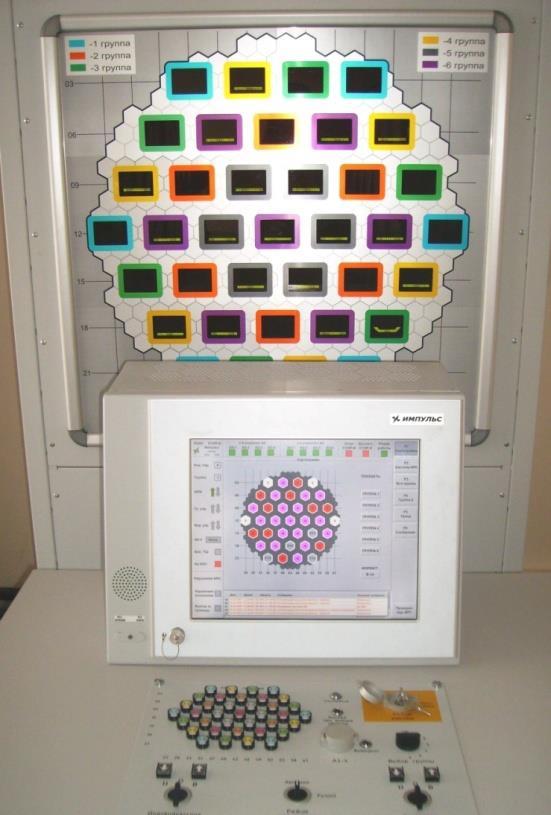
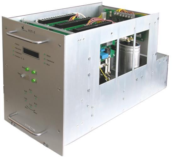
54 RCS-440 Reactor Rod Control System 55
55 Scope and Functions of the RRCS The main functions of the RRCS are o the actuation of the rods that are primarily responsible for the power regulation in the NPP and o carrying out the respective actions according to the operators interventions and the EP-1, EP-3, and EP-4 (Emergency Protection) signals originating from the Reactor Protection System The RRCS incorporates o the logic defining the direction & speed of rod movement o the frequency converters for the servo actuators o the rod position sensors o and the instrumentation and control devices in the main and auxiliary control rooms 56
56 Detailed Functions of the RRCS 1. Holding an individual rod in a given position 2. Moving an individual rod downwards with normal operational speed 3. Moving an individual rod upwards with normal operational speed 4. Moving (dropping) of an individual rod downwards with high speed (in case of EP-1) 5. Arranging rods into groups, realizing the functions F1-F3 for the defined groups 6. Handling the predefined groups, realizing the functions F1-F3 for the predefined groups 7. Controlling the rods downwards in case of EP-3 8. Prohibiting the upward control of rods in case of EP-4 57
57 Qualitative Classification of Consequences Catastrophic o Significant amount of radioactive contaminant released to the environment o Multiple deaths o Long term (e.g. several months) inoperability of a reactor unit Critical o Insignificant amount of radioactive contaminant released to the environment o One death or multiple severe injuries o Medium term (e.g. several days) inoperability of a reactor unit o Significant stress to a reactor unit (e.g. reactor trip/scram is necessary) Marginal o No release of radioactive contaminant to the environment o One severe injury or multiple minor injuries o Short term (e.g. shoutdown) inoperability of a reactor unit Negligible o No release of radioctive contaminant to the environment o One minor injury o Disruption of the normal operation, necessity of operator intervention 58
58 Hazard Identification and the Consequences Function deviation F1. Holding an individual rod in a given position FD1-1. An individual rod remains erroneously in the given position one rod: multiple rods: several rods: FD1-2. Impossible to hold an individual rod in the given position, moves downwards one rod: multiple rods: FD1-3. Impossible to hold an individual rod in the given position, moves upwards one rod: multiple rods: several rods: Consequence Negligible Marginal Critical Negligible Marginal Negligible Marginal Critical 59
59 Tolerable Risk Frequencies Frequency Consequence Catastrophic Critical Marginal Negligible Frequent I I I II Probable I I II III Occasional I II III II Remote II III III IV Improbable III III IV IV Incredible IV IV IV IV Class I: Not permissible, the risk must be reduced by all means Class II: Permissible if and only if the risk is demonstrably cannot be reduced any more Class III: Permissible, but it needs to be examined if the risk can be reduced further in an economical way Class IV: The risk is tolerable without any further action 60
60 Risk Reduction Requirements To get a risk into Class III or below: o In case of catastrophic consequence: improbable or lower frequency of occurrence is needed. The RRCS does not have a function whose deviation can cause catastrophic consequences, due to the fact that the emergency protection is initiated by the safety-critical Reactor Protection System. o In case of critical consequence: remote or lower frequency of occurrence is needed. The RRCS does have functions whose deviation can cause critical consequences, due to the fact that the emergency shutdown of the reactor unit (reactor trip) belongs to this category. o In case of marginal consequence: occasional or lower frequency of occurrence is needed. o In case of negligible consequence: probable or lower frequency of occurrence is needed. 61
61 Quantification of the Hazard Rates Frequent 1 event per 0,1 year THR=10 1/year /h Probable 1 event per 1 year THR=1 1/year /h Occasional 1 event per 10 years THR=0,1 1/year /h Remote 1 event per 100 years THR=0,01 1/year /h Improbable 1 event per 1000 years THR=0,001 1/year /h Incredible 1 event per years THR=0,0001 1/year /h Frequency of occurrence values are assigned according to the safety indices of the NPP and the threshold limits used in the reactor protection system (e.g. allowed frequency of false EP-1 operation is 1 per 100 years) 62
62 Safety Requirements: Tolerable Hazard Rate THR = /h for the following events: o FD.1.1. An individual rod remains erroneously in the given position; several rods event o FD.1.3. Impossible to hold an individual rod in the given position, moves upwards; several rods event o THR = /h for the following events: o FD.1.1. An individual rod remains erroneously in the given position; multiple rods event o FD.1.2. Impossible to hold an individual rod in the given position, moves downwards; multiple rods event o FD.1.3. Impossible to hold an individual rod in the given position, moves upwards; multiple rods event o 63
Understanding safety life cycles
 Understanding safety life cycles IEC/EN 61508 is the basis for the specification, design, and operation of safety instrumented systems (SIS) Fast Forward: IEC/EN 61508 standards need to be implemented
Safety-Critical Systems
 Software Testing & Analysis (F22ST3) Safety-Critical Systems Andrew Ireland School of Mathematical and Computer Science Heriot-Watt University Edinburgh Software Testing & Analysis (F22ST3) 2 What Are
DETERMINATION OF SAFETY REQUIREMENTS FOR SAFETY- RELATED PROTECTION AND CONTROL SYSTEMS - IEC 61508
 DETERMINATION OF SAFETY REQUIREMENTS FOR SAFETY- RELATED PROTECTION AND CONTROL SYSTEMS - IEC 61508 Simon J Brown Technology Division, Health & Safety Executive, Bootle, Merseyside L20 3QZ, UK Crown Copyright
innova-ve entrepreneurial global 1
 www.utm.my innova-ve entrepreneurial global Safety Integrity Level (SIL) is defined as: Relative level of risk-reduction provided by a safety function to specify a target level of risk reduction. SIL is
Marine Risk Assessment
 Marine Risk Assessment Waraporn Srimoon (B.Sc., M.Sc.).) 10 December 2007 What is Risk assessment? Risk assessment is a review as to acceptability of risk based on comparison with risk standards or criteria,
A GUIDE TO RISK ASSESSMENT IN SHIP OPERATIONS
 A GUIDE TO RISK ASSESSMENT IN SHIP OPERATIONS Page 1 of 7 INTRODUCTION Although it is not often referred to as such, the development and implementation of a documented safety management system is an exercise
Safety Analysis: Event Classification
 IAEA Training Course on Safety Assessment of NPPs to Assist Decision Making Safety Analysis: Event Classification Lecturer Lesson IV 1_2 Workshop Information IAEA Workshop City, Country XX - XX Month,
Safety-critical systems: Basic definitions
 Safety-critical systems: Basic definitions Ákos Horváth Based on István Majzik s slides Dept. of Measurement and Information Systems Budapest University of Technology and Economics Department of Measurement
RISK ASSESSMENT HAZARD IDENTIFICATION AND RISK ASSESSMENT METHODOLOGY
 RISK ASSESSMENT HAZARD IDENTIFICATION AND RISK ASSESSMENT METHODOLOGY A) RISK Risk concerns the deviation of one or more results of one or more future events from their expected value. Risk related to
Definition of Safety Integrity Levels and the Influence of Assumptions, Methods and Principles Used
 Definition of Safety Integrity Levels and the Influence of Assumptions, Methods and Principles Used H. Schäbe TÜV InterTraffic, Am Grauen Stein, 51105 Köln, Germany 1 Introduction Methods for derivation
Safety assessments for Aerodromes (Chapter 3 of the PANS-Aerodromes, 1 st ed)
") Safety assessments for Aerodromes (Chapter 3 of the PANS-Aerodromes, 1 st ed) ICAO MID Seminar on Aerodrome Operational Procedures (PANS-Aerodromes) Cairo, November 2017 Avner Shilo, Technical officer
Safety assessments for Aerodromes (Chapter 3 of the PANS-Aerodromes, 1 st ed) ICAO MID Seminar on Aerodrome Operational Procedures (PANS-Aerodromes) Cairo, November 2017 Avner Shilo, Technical officer
Hazard Identification
 Hazard Identification Most important stage of Risk Assessment Process 35+ Techniques Quantitative / Qualitative Failure Modes and Effects Analysis FMEA Energy Analysis Hazard and Operability Studies HAZOP
Risk Management Qualitatively on Railway Signal System
 , pp. 113-117 The Korean Society for Railway Ya-dong Zhang* and Jin Guo** Abstract Risk management is an important part of system assurance and it is widely used in safety-related system. Railway signal
Identification and Screening of Scenarios for LOPA. Ken First Dow Chemical Company Midland, MI
 Identification and Screening of Scenarios for LOPA Ken First Dow Chemical Company Midland, MI 1 Layers of Protection Analysis (LOPA) LOPA is a semi-quantitative tool for analyzing and assessing risk. The
Lecture 04 ( ) Hazard Analysis. Systeme hoher Qualität und Sicherheit Universität Bremen WS 2015/2016
 Hazard Analysis. Systeme hoher Qualität und Sicherheit Universität Bremen WS 2015/2016") Systeme hoher Qualität und Sicherheit Universität Bremen WS 2015/2016 Lecture 04 (02.11.2015) Hazard Analysis Christoph Lüth Jan Peleska Dieter Hutter Where are we? 01: Concepts of Quality 02: Legal Requirements:
Systeme hoher Qualität und Sicherheit Universität Bremen WS 2015/2016 Lecture 04 (02.11.2015) Hazard Analysis Christoph Lüth Jan Peleska Dieter Hutter Where are we? 01: Concepts of Quality 02: Legal Requirements:
SIL explained. Understanding the use of valve actuators in SIL rated safety instrumented systems ACTUATION
 SIL explained Understanding the use of valve actuators in SIL rated safety instrumented systems The requirement for Safety Integrity Level (SIL) equipment can be complicated and confusing. In this document,
Review and Assessment of Engineering Factors
 Review and Assessment of Engineering Factors 2013 Learning Objectives After going through this presentation the participants are expected to be familiar with: Engineering factors as follows; Defense in
Impact on People. A minor injury with no permanent health damage
 Practical Experience of applying Layer of Protection Analysis For Safety Instrumented Systems (SIS) to comply with IEC 61511. Richard Gowland. Director European Process Safety Centre. (Rtgowland@aol.com,
Methods of Determining Safety Integrity Level (SIL) Requirements - Pros and Cons
 Requirements - Pros and Cons") Methods of Determining Safety Integrity Level (SIL) Requirements - Pros and Cons Faeq Azam Khan & Dr. Nihal A. Siddiqui HSE Department, University of Petroleum & Energy Studies, Dehradun, Uttarakhand,
Methods of Determining Safety Integrity Level (SIL) Requirements - Pros and Cons Faeq Azam Khan & Dr. Nihal A. Siddiqui HSE Department, University of Petroleum & Energy Studies, Dehradun, Uttarakhand,
1309 Hazard Assessment Fundamentals
 1309 Hazard Assessment Fundamentals Jim Marko Manager, Aircraft Integration & Safety Assessment 14 November 2018 Presentation Overview Fail-safe design concept Safety Assessment principles for hazard classification
DATA ITEM DESCRIPTION Title: Failure Modes, Effects, and Criticality Analysis Report
 DATA ITEM DESCRIPTION Title: Failure Modes, Effects, and Criticality Analysis Report Number: Approval Date: 20160106 AMSC Number: N9616 Limitation: No DTIC Applicable: Yes GIDEP Applicable: Yes Defense
C. Mokkapati 1 A PRACTICAL RISK AND SAFETY ASSESSMENT METHODOLOGY FOR SAFETY- CRITICAL SYSTEMS
 C. Mokkapati 1 A PRACTICAL RISK AND SAFETY ASSESSMENT METHODOLOGY FOR SAFETY- CRITICAL SYSTEMS Chinnarao Mokkapati Ansaldo Signal Union Switch & Signal Inc. 1000 Technology Drive Pittsburgh, PA 15219 Abstract
Solenoid Valves used in Safety Instrumented Systems
 I&M V9629R1 Solenoid Valves used in Safety Instrumented Systems Operating Manual in accordance with IEC 61508 ASCO Valves Page 1 of 7 Table of Contents 1 Introduction...3 1.1 Terms and Abbreviations...3
A study on the relation between safety analysis process and system engineering process of train control system
 A study on the relation between safety analysis process and system engineering process of train control system Abstract - In this paper, the relationship between system engineering lifecycle and safety
LECTURE 3 MAINTENANCE DECISION MAKING STRATEGIES (RELIABILITY CENTERED MAINTENANCE)
") LECTURE 3 MAINTENANCE DECISION MAKING STRATEGIES (RELIABILITY CENTERED MAINTENANCE) Politecnico di Milano, Italy piero.baraldi@polimi.it 1 Types of maintenance approaches Intervention Unplanned Planned
LECTURE 3 MAINTENANCE DECISION MAKING STRATEGIES (RELIABILITY CENTERED MAINTENANCE) Politecnico di Milano, Italy piero.baraldi@polimi.it 1 Types of maintenance approaches Intervention Unplanned Planned
DeZURIK Double Block & Bleed (DBB) Knife Gate Valve Safety Manual
 Knife Gate Valve Safety Manual") Double Block & Bleed (DBB) Knife Gate Valve Safety Manual Manual D11044 September, 2015 Table of Contents 1 Introduction... 3 1.1 Terms... 3 1.2 Abbreviations... 4 1.3 Product Support... 4 1.4 Related
Double Block & Bleed (DBB) Knife Gate Valve Safety Manual Manual D11044 September, 2015 Table of Contents 1 Introduction... 3 1.1 Terms... 3 1.2 Abbreviations... 4 1.3 Product Support... 4 1.4 Related
FP15 Interface Valve. SIL Safety Manual. SIL SM.018 Rev 1. Compiled By : G. Elliott, Date: 30/10/2017. Innovative and Reliable Valve & Pump Solutions
 SIL SM.018 Rev 1 FP15 Interface Valve Compiled By : G. Elliott, Date: 30/10/2017 FP15/L1 FP15/H1 Contents Terminology Definitions......3 Acronyms & Abbreviations...4 1. Introduction...5 1.1 Scope.. 5 1.2
Hazard analysis. István Majzik Budapest University of Technology and Economics Dept. of Measurement and Information Systems
 Hazard analysis István Majzik Budapest University of Technology and Economics Dept. of Measurement and Information Systems Hazard analysis Goal: Analysis of the fault effects and the evolution of hazards
RISK ASSESSMENT. White Paper.
 RISK ASSESSMENT White Paper www.leuze.com White Paper RISK ASSESSMENT IN HARMONY The European Machinery Directive as well as its implementations on a national level (in Germany ProdSG and 9 ProdSV) require
DeZURIK. KSV Knife Gate Valve. Safety Manual
 KSV Knife Gate Valve Safety Manual Manual D11035 August 29, 2014 Table of Contents 1 Introduction... 3 1.1 Terms... 3 1.2 Abbreviations... 4 1.3 Product Support... 4 1.4 Related Literature... 4 1.5 Reference
Safety of railway control systems: A new Preliminary Risk Analysis approach
 Author manuscript published in IEEE International Conference on Industrial Engineering and Engineering Management Singapour : Singapour (28) Safety of railway control systems: A new Preliminary Risk Analysis
Using what we have. Sherman Eagles SoftwareCPR.
 Using what we have Sherman Eagles SoftwareCPR seagles@softwarecpr.com 2 A question to think about Is there a difference between a medical device safety case and any non-medical device safety case? Are
Purpose. Scope. Process flow OPERATING PROCEDURE 07: HAZARD LOG MANAGEMENT
 SYDNEY TRAINS SAFETY MANAGEMENT SYSTEM OPERATING PROCEDURE 07: HAZARD LOG MANAGEMENT Purpose Scope Process flow This operating procedure supports SMS-07-SP-3067 Manage Safety Change and establishes the
Solenoid Valves For Gas Service FP02G & FP05G
 SIL Safety Manual SM.0002 Rev 02 Solenoid Valves For Gas Service FP02G & FP05G Compiled By : G. Elliott, Date: 31/10/2017 Reviewed By : Peter Kyrycz Date: 31/10/2017 Contents Terminology Definitions......3
Pneumatic QEV. SIL Safety Manual SIL SM Compiled By : G. Elliott, Date: 8/19/2015. Innovative and Reliable Valve & Pump Solutions
 SIL SM.0010 1 Pneumatic QEV Compiled By : G. Elliott, Date: 8/19/2015 Contents Terminology Definitions......3 Acronyms & Abbreviations..4 1. Introduction 5 1.1 Scope 5 1.2 Relevant Standards 5 1.3 Other
DeZURIK. KGC Cast Knife Gate Valve. Safety Manual
 KGC Cast Knife Gate Valve Safety Manual Manual D11036 August 29, 2014 Table of Contents 1 Introduction... 3 1.1 Terms... 3 1.2 Abbreviations... 4 1.3 Product Support... 4 1.4 Related Literature... 4 1.5
Accelerometer mod. TA18-S. SIL Safety Report
 Accelerometer mod. TA18-S SIL Safety Report SIL005/11 rev.1 of 03.02.2011 Page 1 of 7 1. Field of use The transducers are made to monitoring vibrations in systems that must meet particular technical safety
Safety Critical Systems
 Safety Critical Systems Mostly from: Douglass, Doing Hard Time, developing Real-Time Systems with UML, Objects, Frameworks And Patterns, Addison-Wesley. ISBN 0-201-49837-5 1 Definitions channel a set of
Safety Management in Multidisciplinary Systems. SSRM symposium TA University, 26 October 2011 By Boris Zaets AGENDA
 Safety Management in Multidisciplinary Systems SSRM symposium TA University, 26 October 2011 By Boris Zaets 2008, All rights reserved. No part of this material may be reproduced, in any form or by any
Advanced LOPA Topics
 11 Advanced LOPA Topics 11.1. Purpose The purpose of this chapter is to discuss more complex methods for using the LOPA technique. It is intended for analysts who are competent with applying the basic
QUANTIFYING THE TOLERABILITY OF POTENTIAL IGNITION SOURCES FROM UNCERTIFIED MECHANICAL EQUIPMENT INSTALLED IN HAZARDOUS AREAS
 QUANTIFYING THE TOLERABILITY OF POTENTIAL IGNITION SOURCES FROM UNCERTIFIED MECHANICAL EQUIPMENT INSTALLED IN HAZARDOUS AREAS Steve Sherwen Senior Consultant, ABB Engineering Services, Daresbury Park,
PL estimation acc. to EN ISO
 PL estimation acc. to EN ISO 3849- Example calculation for an application MAC Safety / Armin Wenigenrath, January 2007 Select the suitable standard for your application Reminder: The standards and the
Workshop Functional Safety
 Workshop Functional Safety Nieuwegein 12 March 2014 Workshop Functional Safety VDMA 4315 Part 1 page 1 Agenda VDMA Working Group on Functional Safety Functional Safety and Safety Lifecycle Functional Safety
SPR - Pneumatic Spool Valve
 SIL SM.008 Rev 7 SPR - Pneumatic Spool Valve Compiled By : G. Elliott, Date: 31/08/17 Contents Terminology Definitions:... 3 Acronyms & Abbreviations:... 4 1.0 Introduction... 5 1.1 Purpose & Scope...
Employ The Risk Management Process During Mission Planning
 Employ The Risk Management Process During Mission Planning TSG 154-6465 Task(s) TASK NUMBER TASK TITLE Taught or 154-385-6465 Employ The Risk Management Process During Mission Planning Supported Task(s)
This manual provides necessary requirements for meeting the IEC or IEC functional safety standards.
 Instruction Manual Supplement Safety manual for Fisher Vee-Ball Series Purpose This safety manual provides information necessary to design, install, verify and maintain a Safety Instrumented Function (SIF)
Managing for Liability Avoidance. (c) Lewis Bass
 Lewis Bass") Managing for Liability Avoidance (c) Lewis Bass 2005 1 Staying Safe in an Automated World Keys to Automation Safety and Liability Avoidance Presented by: Lewis Bass, P.E. Mechanical, Industrial and Safety
Managing for Liability Avoidance (c) Lewis Bass 2005 1 Staying Safe in an Automated World Keys to Automation Safety and Liability Avoidance Presented by: Lewis Bass, P.E. Mechanical, Industrial and Safety
RESILIENT SEATED BUTTERFLY VALVES FUNCTIONAL SAFETY MANUAL
 Per IEC 61508 and IEC 61511 Standards BRAY.COM Table of Contents 1.0 Introduction.................................................... 1 1.1 Terms and Abbreviations...........................................
Aeronautical studies and Safety Assessment
 Aerodrome Safeguarding Workshop Cairo, 4 6 Dec. 2017 Aeronautical studies and Safety Assessment Nawal A. Abdel Hady ICAO MID Regional Office, Aerodrome and Ground Aids (AGA) Expert References ICAO SARPS
Bespoke Hydraulic Manifold Assembly
 SIL SM.0003 1 Bespoke Hydraulic Manifold Assembly Compiled By : G. Elliott, Date: 12/17/2015 Contents Terminology Definitions......3 Acronyms & Abbreviations..4 1. Introduction 5 1.1 Scope 5 1.2 Relevant
Safety Standards Acknowledgement and Consent (SSAC) CAP 1395
 CAP 1395") Safety Standards Acknowledgement and Consent (SSAC) CAP 1395 Contents Published by the Civil Aviation Authority, 2015 Civil Aviation Authority, Aviation House, Gatwick Airport South, West Sussex, RH6 0YR.
Safety Standards Acknowledgement and Consent (SSAC) CAP 1395 Contents Published by the Civil Aviation Authority, 2015 Civil Aviation Authority, Aviation House, Gatwick Airport South, West Sussex, RH6 0YR.
Hydraulic (Subsea) Shuttle Valves
 Shuttle Valves") SIL SM.009 0 Hydraulic (Subsea) Shuttle Valves Compiled By : G. Elliott, Date: 11/3/2014 Contents Terminology Definitions......3 Acronyms & Abbreviations..4 1. Introduction 5 1.1 Scope 5 1.2 Relevant Standards
SIL SM.009 0 Hydraulic (Subsea) Shuttle Valves Compiled By : G. Elliott, Date: 11/3/2014 Contents Terminology Definitions......3 Acronyms & Abbreviations..4 1. Introduction 5 1.1 Scope 5 1.2 Relevant Standards
Ultima. X Series Gas Monitor
 Ultima X Series Gas Monitor Safety Manual SIL 2 Certified " The Ultima X Series Gas Monitor is qualified as an SIL 2 device under IEC 61508 and must be installed, used, and maintained in accordance with
Implementing IEC Standards for Safety Instrumented Systems
 Implementing IEC Standards for Safety Instrumented Systems ABHAY THODGE TUV Certificate: PFSE-06-607 INVENSYS OPERATIONS MANAGEMENT What is a Safety Instrumented System (SIS)? An SIS is designed to: respond
SIL Safety Manual. ULTRAMAT 6 Gas Analyzer for the Determination of IR-Absorbing Gases. Supplement to instruction manual ULTRAMAT 6 and OXYMAT 6
 ULTRAMAT 6 Gas Analyzer for the Determination of IR-Absorbing Gases SIL Safety Manual Supplement to instruction manual ULTRAMAT 6 and OXYMAT 6 ULTRAMAT 6F 7MB2111, 7MB2117, 7MB2112, 7MB2118 ULTRAMAT 6E
The Best Use of Lockout/Tagout and Control Reliable Circuits
 Session No. 565 The Best Use of Lockout/Tagout and Control Reliable Circuits Introduction L. Tyson Ross, P.E., C.S.P. Principal LJB Inc. Dayton, Ohio Anyone involved in the design, installation, operation,
Eutectic Plug Valve. SIL Safety Manual. SIL SM.015 Rev 0. Compiled By : G. Elliott, Date: 19/10/2016. Innovative and Reliable Valve & Pump Solutions
 SIL SM.015 Rev 0 Eutectic Plug Valve Compiled By : G. Elliott, Date: 19/10/2016 Contents Terminology Definitions......3 Acronyms & Abbreviations...4 1. Introduction..5 1.1 Scope 5 1.2 Relevant Standards
PROCESS AUTOMATION SIL. Manual Safety Integrity Level. Edition 2005 IEC 61508/61511
 PROCESS AUTOMATION Manual Safety Integrity Level SIL Edition 2005 IEC 61508/61511 With regard to the supply of products, the current issue of the following document is applicable: The General Terms of
CT433 - Machine Safety
 Rockwell Automation On The Move May 16-17 2018 Milwaukee, WI CT433 - Machine Safety Performance Level Selection and Design Realization Jon Riemer Solution Architect Safety & Security Functional Safety
Session Fifteen: Protection Functions as Probabilistic Filters for Accidents
 Abstract Session Fifteen: Protection Functions as Probabilistic Filters for Accidents Andreas Belzner Engine Functional Safety Gas Turbine, Alstom A generalized model is developed for the risk reduction
COMMON MISUNDERSTANDINGS ABOUT THE PRACTICAL APPLICATION OF IEC 61508
 COMMON MISUNDERSTANDINGS ABOUT THE PRACTICAL APPLICATION OF IEC 61508 Helen Pearce, James Catmur and Geoff Stevens The use of IEC 61508 for determination of the Safety Integrity Level (SIL) of Safety Interlock
Proposal title: Biogas robust processing with combined catalytic reformer and trap. Acronym: BioRobur
 Proposal title: Biogas robust processing with combined catalytic reformer and trap Acronym: BioRobur Initiative: Fuel Cells and Hydrogen Joint Undertaking (FCH-JU) Funding scheme: Collaborative project
Valve Communication Solutions. Safety instrumented systems
 Safety instrumented systems Safety Instrumented System (SIS) is implemented as part of a risk reduction strategy. The primary focus is to prevent catastrophic accidents resulting from abnormal operation.
ESSENTIAL SAFETY RESOURCES
 ESSENTIAL SAFETY RESOURCES GS-3018 HAZARD IDENTIFICATION AND RISK ASSESSMENT Originator: Safety Advisor s Signature: Type Name Approval: HSE Manager s Signature: Type Name Approval: Operations Manager
PI MODERN RELIABILITY TECHNIQUES OBJECTIVES. 5.1 Describe each of the following reliability assessment techniques by:
 PI 21. 05 PI 21. 05 MODERN RELIABILITY TECHNIQUES OBJECTIVES 5.1 Describe each of the following reliability assessment techniques by: ~) Stating its purpose. i1) Giving an e ample of where it is used.
Pressure Equipment Directive PED 2014/68/EU Commission's Working Group "Pressure"
 H. INTERPRETATION OF OTHER ESSENTIAL SAFETY REQUIREMENTS Guideline H-02 Guideline related to: Annex I Section 3.2.2 and 7.4 Final assessment (Annex I Section 3.2.2) of pressure equipment must include a
Safety and efficiency go hand in hand at MVM Paks NPP
 International Forum Atomexpo 2018 Safety and efficiency go hand in hand at MVM Paks NPP József Elter MVM Paks Nuclear Power Plant Ltd. Hungary Start up Four of the VVER-440/V213 unit Power units up-rate
Partial Stroke Testing. A.F.M. Prins
 Partial Stroke Testing A.F.M. Prins Partial Stroke Testing PST in a safety related system. As a supplier we have a responsibility to our clients. What do they want, and what do they really need? I like
Enhancing NPP Safety through an Effective Dependability Management
 Prepared and presented by Gheorghe VIERU, PhD Senior Scientific Nuclear Security Research Worker AREN/c.o. Institute for Nuclear Research Pitesti, ROMANIA Safety: Defence in Depth, October 2013 1 OUTLINES
ALIGNING MOD POSMS SAFETY AND POEMS ENVIRONMENTAL RISK APPROACHES EXPERIENCE AND GUIDANCE
 ALIGNING MOD POSMS SAFETY AND POEMS ENVIRONMENTAL RISK APPROACHES EXPERIENCE AND GUIDANCE R. L. Maguire MIMechE MSaRS RS2A Limited Swindon, UK 07505 743 725 rlm@rs2a.com Keywords: POSMS, POEMS, Alignment,
Risks Associated with Caissons on Ageing Offshore Facilities
 Risks Associated with Caissons on Ageing Offshore Facilities D. Michael Johnson, DNV GL, Peter Joyce, BG Group, Sumeet Pabby, BG Group, Innes Lawtie, BG Group. Neil Arthur, BG Group, Paul Murray, DNV GL.
1.0 PURPOSE 2.0 REFERENCES
 Page 1 1.0 PURPOSE 1.1 This Advisory Circular provides Aerodrome Operators with guidance for the development of corrective action plans to be implemented in order to address findings generated during safety
EXPLOSIVE ATMOSPHERES - CLASSIFICATION OF HAZARDOUS AREAS (ZONING) AND SELECTION OF EQUIPMENT
 AND SELECTION OF EQUIPMENT") EXPLOSIVE ATMOSPHERES - CLASSIFICATION OF HAZARDOUS AREAS (ZONING) AND SELECTION OF EQUIPMENT OVERVIEW ASSESSING THE RISK RELATIONSHIP BETWEEN FIRES AND EXPLOSIONS CLASSIFYING HAZARDOUS AREAS INTO ZONES
EXPLOSIVE ATMOSPHERES - CLASSIFICATION OF HAZARDOUS AREAS (ZONING) AND SELECTION OF EQUIPMENT OVERVIEW ASSESSING THE RISK RELATIONSHIP BETWEEN FIRES AND EXPLOSIONS CLASSIFYING HAZARDOUS AREAS INTO ZONES
Module No. # 03 Lecture No. # 01 Dose assessment, Safety regulations
 Health, Safety and Environmental Management in Petroleum and offshore Engineering Prof. Dr. Srinivasan Chandrasekaran Department of Ocean Engineering Indian Institute of Technology, Madras Module No. #
Every things under control High-Integrity Pressure Protection System (HIPPS)
") Every things under control www.adico.co info@adico.co Table Of Contents 1. Introduction... 2 2. Standards... 3 3. HIPPS vs Emergency Shut Down... 4 4. Safety Requirement Specification... 4 5. Device Integrity
Every things under control www.adico.co info@adico.co Table Of Contents 1. Introduction... 2 2. Standards... 3 3. HIPPS vs Emergency Shut Down... 4 4. Safety Requirement Specification... 4 5. Device Integrity
TRI LOK SAFETY MANUAL TRI LOK TRIPLE OFFSET BUTTERFLY VALVE. The High Performance Company
 TRI LOK TRI LOK TRIPLE OFFSET BUTTERFLY VALVE SAFETY MANUAL The High Performance Company Table of Contents 1.0 Introduction...1 1.1 Terms and Abbreviations... 1 1.2 Acronyms... 1 1.3 Product Support...
Risk Management. Definitions. Principles of Risk Management. Types of Risk
 Definitions Risk Management Risk management is a decision-making process designed to identify hazards systematically, assess the degree of risk, and determine the best course of action. It is a practical
OBJECTIVE 6: FIELD RADIOLOGICAL MONITORING - AMBIENT RADIATION MONITORING
 OBJECTIVE 6: FIELD RADIOLOGICAL MONITORING - AMBIENT RADIATION MONITORING OBJECTIVE Demonstrate the appropriate use of equipment and procedures for determining field radiation measurements. INTENT This
Safety manual for Fisher GX Control Valve and Actuator
 Instruction Manual Supplement GX Valve and Actuator Safety manual for Fisher GX Control Valve and Actuator Purpose This safety manual provides information necessary to design, install, verify and maintain
Reliability of Safety-Critical Systems Chapter 3. Failures and Failure Analysis
 Reliability of Safety-Critical Systems Chapter 3. Failures and Failure Analysis Mary Ann Lundteigen and Marvin Rausand mary.a.lundteigen@ntnu.no RAMS Group Department of Production and Quality Engineering
Tools for safety management Effectiveness of risk mitigation measures. Bernhard KOHL
 Tools for safety management Effectiveness of risk mitigation measures Bernhard KOHL Contents Background Tools for risk-based decision making Safety measures Illustration of methodical approach Case studies
Using LOPA for Other Applications
 10 Using LOPA for Other Applications 10.1. Purpose LOPA is a tool used to perform risk assessments. Previous chapters described its use in assessing the risk level of process hazards scenarios and in evaluating
Module No. # 04 Lecture No. # 3.1 Case studies (continued) (Refer Slide Time: 00:10)
 (Refer Slide Time: 00:10)") Health, Safety and Environmental Management in Petroleum and offshore Engineering Prof. Dr. Srinivasan Chandrasekaran Department of Ocean Engineering Indian Institute of Technology, Madras Module No. #
Health, Safety and Environmental Management in Petroleum and offshore Engineering Prof. Dr. Srinivasan Chandrasekaran Department of Ocean Engineering Indian Institute of Technology, Madras Module No. #
New Airfield Risk Assessment / Categorisation
 New Airfield Risk Assessment / Categorisation Airfield Risk Assessment Prior to commencing operations to a new airfield, airfield risk assessment and categorisation will take place. For continued operations
Guideline Meaning of duty to ensure safety so far as is reasonably practicable - SFAIRP
 Guideline Meaning of duty to ensure safety so far as is reasonably practicable - SFAIRP Title of the document National Rail Safety Regulator Page1of15 Document reference number: A390705 Version No. Approved
PRACTICAL EXAMPLES ON CSM-RA
 PRACTICAL EXAMPLES ON CSM-RA Common Safety Method: What for? How? 0 SNCF Training in Budapest Technical University on CSM-RA SUMMARY CSM-RA A short history summary CSM-RA understanding What is there to
Considerations for the Practical Application of the Safety Requirements for Nuclear Power Plant Design
 Considerations for the Practical Application of the Safety Requirements for Nuclear Power Plant Design Joint ICTP-IAEA Essential Knowledge Workshop on Deterministic Safety Analysis and Engineering Aspects
Industrial Risk Management
 Industrial Risk Management Raúl Manga Valenzuela Risk Analyst Repsol Exploración perú In theory, theory and practice are the same. In practice they are not Albert Einstein 1 An intuitive process Setting
Section 1: Multiple Choice
 CFSP Process Applications Section 1: Multiple Choice EXAMPLE Candidate Exam Number (No Name): Please write down your name in the above provided space. Only one answer is correct. Please circle only the
Federal Aviation Administration Safety & Human Factors Analysis of a Wake Vortex Mitigation Display System
 Safety & Human Factors Analysis of a Wake Vortex Mitigation Display System Presented to: EUROCONTROL Safety R&D Seminar By: Dino Piccione Date: October 23, 2008 Project Objectives Forge a link between
New Thinking in Control Reliability
 Doug Nix, A.Sc.T. Compliance InSight Consulting Inc. New Thinking in Control Reliability Or Your Next Big Headache www.machinerysafety101.com (519) 729-5704 Control Reliability Burning Questions from the
SEMS II: BSEE should focus on eliminating human error
 SEMS II: BSEE should focus on eliminating human error How US companies can prevent accidents on start-ups and shut-downs by using valve interlocks The proposed changes to BSEE s SEMS (Safety and Environmental
The Safety Case. Structure of Safety Cases Safety Argument Notation
 The Safety Case Structure of Safety Cases Safety Argument Notation Budapest University of Technology and Economics Department of Measurement and Information Systems The safety case Definition (core): The
Critical Systems Validation
 Critical Systems Validation Objectives To explain how system reliability can be measured and how reliability growth models can be used for reliability prediction To describe safety arguments and how these
SAFETY SEMINAR Rio de Janeiro, Brazil - August 3-7, Authors: Francisco Carlos da Costa Barros Edson Romano Marins
 SAFETY SEINAR Rio de Janeiro, Brazil - August 3-7, 2009 Using HAZOP and LOPA ethodologies to Improve Safety in the Coke Drums Cycles Authors: Gilsa Pacheco onteiro Francisco Carlos da Costa Barros Edson
Regional Workshop on the International Basic Safety Standards. Session 10: Emergency Preparedness and Response
 Regional Workshop on the International Basic Safety Standards Session 10: Emergency Preparedness and Response 16-19 October 2012, Kiev, Ukraine Vladimir Kutkov Incident and Emergency Centre International
Analysis of Safety Requirements for MODSafe Continuous Safety Measures and Functions
 European Commission Seventh Framework programme MODSafe Modular Urban Transport Safety and Security Analysis WP 4 - D4.2 Analysis of Safety Requirements for MODSafe Continuous Safety Measures and Reviewed
FLIGHT TEST RISK ASSESSMENT THREE FLAGS METHOD
 FLIGHT TEST RISK ASSESSMENT THREE FLAGS METHOD Author: Maximilian Kleinubing BS. Field: Aeronautical Engineering, Flight Test Operations Keywords: Flight Test, Safety Assessment, Flight Test Safety Assessment
POWER Quantifying Correction Curve Uncertainty Through Empirical Methods
 Proceedings of the ASME 2014 Power Conference POWER2014 July 28-31, 2014, Baltimore, Maryland, USA POWER2014-32187 Quantifying Correction Curve Uncertainty Through Empirical Methods ABSTRACT Christopher
Module No. # 01 Lecture No. # 6.2 HAZOP (continued)
") Health, Safety and Environmental Management in Petroleum and Offshore Engineering Prof. Srinivasan Chandrasekaran Department of Ocean Engineering Indian Institute Of Technology, Madras Module No. # 01
Health, Safety and Environmental Management in Petroleum and Offshore Engineering Prof. Srinivasan Chandrasekaran Department of Ocean Engineering Indian Institute Of Technology, Madras Module No. # 01