Operating instructions. Surge arrester Type MVR
|
|
|
- Iris McDonald
- 6 years ago
- Views:
Transcription
1 Operating instructions Surge arrester Type MVR
2 Content 1 About this document Validity Target group Safety Symbols and advices Basic safety precautions Product safety Personnel-related measures Organisational measures Description Intended use Structure and function Technical data Technical data on the surge arrester Application guidelines Behaviour in fire Transportation, Unpacking and Storage Transportation Unpacking Storage Commissioning Safety Electrical check before commissioning Installation location and protective distance Mounting System voltage Installation position Minimum distances between surge arresters and earth Connections Earthing Maintenance, Upkeep Safety Replacement after overloading Disposal Operating instructions EN 1HC AD
3 1 About this document These operating instructions are part of the MVR surge arrester and describe safe and proper use for all phases of operation. Language of the original operating instructions: German 1.1 Validity These operating instructions are valid only for the MVR surge arrester. 1.2 Target group The target group of these operating instructions is professionals in the field of high-voltage technology. The MVR may only be commissioned and maintained by persons instructed in proper use and handling. 2 Safety 2.1 Symbols and advices Important information and technical notes are emphasised in order to illustrate the correct operation. Symbol Meaning This is a safety sign. It warns you of the danger of injury and material damage. Follow all measures marked with the safety sign to avoid injuries, death and damage to materials. This safety sign warns you of the danger of death or serious injury from electric shocks. Follow all measures marked with the safety sign to avoid injuries and death. X X This mark indicates that an action is to be performed. Warnings in these operating instructions indicate special dangers and list measures for prevention of the danger. There are three levels of warning: Warning word DANGER WARNING CAUTION Meaning Immediate, impending endangerment of your life and health Possible impending endangerment of your life and health Possible impending danger of light injuries or damage to materials Warnings are structured as follows: WARNING WORD! The type and source of danger appear here. Possible consequences, which could occur if the measures are not followed, appear here. Measures for avoiding the danger appear here. 1HC AD EN Operating instructions 3
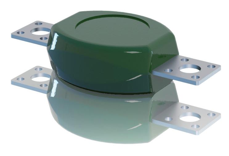
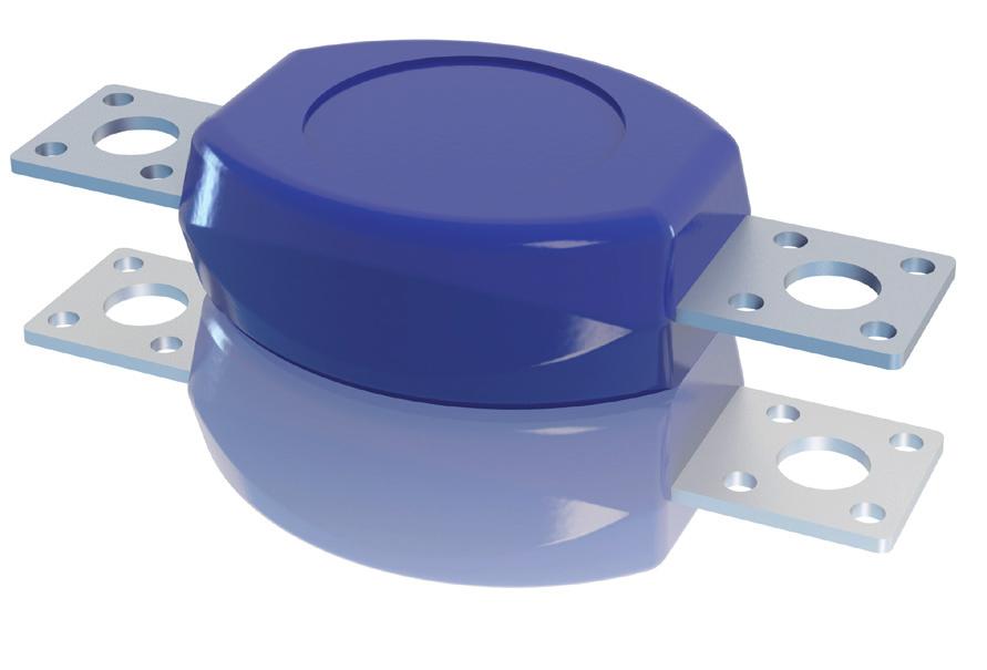
4 2.2 Basic safety precautions Product safety The MVR has been constructed using state-of-the-art technology and officially recognised safetyrelated rules. Danger to life and health of the user or third parties could arise or damage of the MVR and other property could occur while the MVR is in use, however. The MVR is only to be used when it is in technically sound condition, for the intended purpose, and with safety and the possible dangers in mind while observing the operating instructions. Keep the operating instructions intact and fully readable, and store them in such a way that they are accessible to operating personnel at all times. Decommission and replace overloaded or damaged MVR units Personnel-related measures Train personnel in professional and safe working with high-voltage technology. Train and instruct personnel in working on the MVR using the operating instructions. Personnel being trained, instructed or provided with general education may only work with the MVR under constant supervision by an experienced high-voltage technology professional Organisational measures Observe all safety- and danger-related information regarding the MVR. The safety rules of the owner of the high- and medium-voltage system and all regulations of the respective national safety authorities are to be observed. Only trained and instructed professionals may be authorised. Clearly assign areas of responsibility for working with the MVR. Make them known and adhere to them. Only personnel who have read and understood the operating instructions, especially the Basic safety precautions section may be allowed to carry out activities with the MVR. Check to ensure that work is being performed in a safety-conscious way with awareness of possible dangers and while observing the operating instructions. 3 Description 3.1 Intended use The MVR is a surge arrester intended for use in low- and medium-voltage applications. Surge arresters protect the insulation of devices against unacceptable over-voltages which are caused by lightning or switching operations. The manufacturer is not liable for resulting damages from further, unintended use. The operator accepts all responsibility for using the MVR outside of its intended application range as specified in this document. 3.2 Structure and function The MVR surge arrester is constructed from one or more non-linear metal-oxide (MO) resistors. These MO resistors have an extremely non-linear resistance property. At the maximum operating voltage of U c, only a small capacitive current will flow in the ma range. With an increase in voltage, the MO resistors enter a highly-conductive state practically without delay. Thus any further increase in voltage is limited to the specified residual voltage values. After the decline of the overvoltage the arrester immediately turns back to the non- or slightly-conductive state. The MO arrester converts the energy of the surge into heat, which it transfers to the surrounding air. 4 Operating instructions EN 1HC AD
5 The MO-resistor or stack of MO resistors is connected with the terminals. The directly molded PUR housing protects it from all environmental and weather influences. This design has proven to be the best solution in every environment for years. The MVR is especially suited for overvoltage protection of: transformers cables and cable sheath capacitors other low- and medium-voltage apparatuses and systems The surge arresters MVR K5/K10 are suitable for the use in a.c. and d.c. systems. The surge arresters MVR G5/G10 are suitable for the use in a.c. systems, only. 3.3 Technical data The technical data, dimensions, weights and installation distances are specified in the following documents: surge arresters MVR K5 in the pamphlet 1HC surge arresters MVR K10 in the pamphlet 1HC surge arresters MVR G5 in the pamphlet 1HC surge arresters MVR G10 in the pamphlet 1HC Technical data on the surge arrester The rating plate molded in PUR for MVR K5/K10 contains the following data: Data Meaning MVR... K.. Type designation K5 for I n = 5 ka K10 for I n = 10 ka... V AC Maximum permissible continuous operating voltage U c for a.c. applications... V DC Maximum permissible continuous operating voltage U c for d.c. applications 20xx Year of manufacture The rating plate molded in PUR for MVR G5/G10 contains the following data: Data Meaning MVR... G.. Type designation G5 for I n = 5 ka G10 for I n = 10 ka Uc kv Maximum permissible continuous operating voltage U c for a.c. applications Ur kv Rated voltage U r for a.c. applications In ka Nominal discharge current I n Identification number (optional) 20xx Year of manufacture Application guidelines The following guidelines apply for the use of MVR surge arresters: Application guidelines - Overvoltage potection Dimensioning, testing and application of metaloxide surge arrresters in medium voltage systems, pamphlet 1HC Behaviour in fire The PUR housing of the surge arrester is not self-extinguishing. 1HC AD EN Operating instructions 5
6 4 Transportation, Unpacking and Storage 4.1 Transportation CAUTION! Improper handling during transportation. Damage to surge arresters due to improper handling. Observe safety precautions printed on the packaging for proper handling during transportation and storage. Secure surge arresters against falling before transportation. 4.2 Unpacking The surge arresters provided are packaged in stable cardboard boxes or wooden crates. The routine test report for the final electrical inspection is included in the packaging material. After receiving the shipment, compare the order and delivery documents immediately to check for completeness and accuracy of the shipment. In case of incompleteness or deviations, inform the supplier and shipper immediately. WARNING! Damaged surge arresters. Material damage and personal injury due to the installation and commissioning of damaged surge arresters. Do not use damaged surge arresters. Examine shipment immediately to check for damage. Notify the insurance company, the shipper and the supplier of the damage immediately and create a damage log. 4.3 Storage The original packaging materials can be used for storage. Store surge arresters in a well-ventilated, clean room. Remove plastic film to prevent the formation of condensation water. Storage temperature: C 6 Operating instructions EN 1HC AD
7 5 Commissioning 5.1 Safety DANGER! System uses high voltage. Death, serious bodily harm and damage to the switching gear may result from an electric shock. Allow only authorised professionals to perform work on the surge arrester. Observe the safety rules of EN before working on the system: Disconnect the system from the power supply. Secure the system against being switched on again. Ensure that the system is deenergised. Earth the system and short-circuit it. Cover or cordon off neighbouring energised parts. 5.2 Electrical check before commissioning Each surge arrester is tested by the manufacturer. Additional electrical testing before commissioning is not necessary. 5.3 Installation location and protective distance DANGER! Danger of fire and injury with overloading of the surge arrester. Danger of injury from bursting plastic and flying (housing) parts. Mount the surge arrester with a suitable cover or in a safe distance. Ignition of flammable materials by an arc and flying burning parts. Do not store flammable materials near the surge arrester. When working near the surge arrester, do not wear easily flammable clothing. Surge arresters only protect medium-voltage and low-voltage apparatuses when they are located within the protective distance The protective distance is only a few meters. Always mount surge arresters as close as possible to the apparatus to be protected within the protective distance. The length of the connecting cables are decisive here. In cases of doubt, calculate the protective distance according to the formulas in the Application guidelines. 1HC AD EN Operating instructions 7
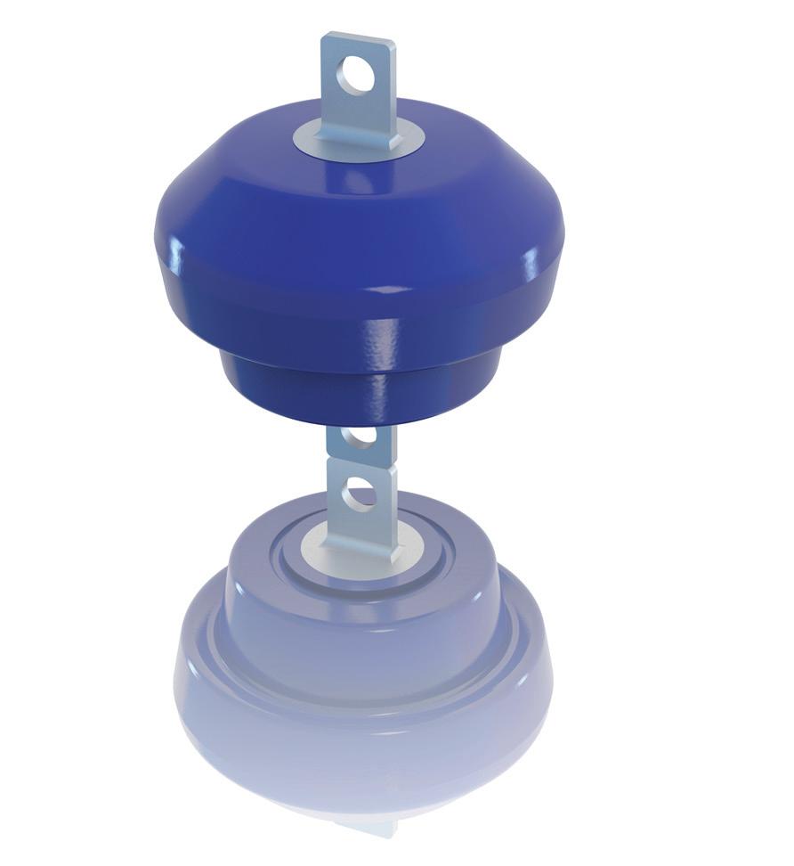
8 5.4 Mounting System voltage CAUTION! Damage to the surge arrester during insulation test. The surge arrester may be overloaded (damaged) if it is mounted during the insulation test of the system. Disconnect surge arrester from switchgear during insulation tests. CAUTION! Incorrect system voltage. Damage to the switching gear and the surge arrester. Do not use surge arresters MVR G5/G10 intended for a.c. systems in d.c. systems. Observe the Application guidelines from ABB Switzerland Ltd. Before mounting, ensure that the characteristic data on the rating plate of the surge arrester matches the requirements of the power system. Ensure that the system voltage applied at the terminals of the arrester does not exceed the maximum permissible continuous operating voltage of the surge arrester Installation position CAUTION! Deposits on the undersides of sheds. Conductivity of deposits hinders protective function of the MVR G5/G10. Always mount surge arresters in such a way that the sheds point downward. MVR K5/K10 can be mounted in each position Minimum distances between surge arresters and earth Observe national regulations and the rules of the system owner regarding minimum permissible distances between the surge arresters and the earth. Mount the surge arrester with a suitable cover or in a safe distance Connections The following materials made of stainless or galvanised steel are to be provided by the customer: bolts nuts washers bolt locks The design of the surge arrester MVR is symmetrical. Connect one terminal of the surge arrester with earth. Connect the high voltage connection with the other terminal of the surge arrester. Use a stranded cable. Carefully clean contact surfaces before mounting and lubricate with acid-free contact grease. Ensure selection of suitable material pairs 8 Operating instructions EN 1HC AD
9 5.5 Earthing Observe national regulations and the requirements of the system owner. Connect surge arresters to the system ground via the shortest path. Carefully clean contact surfaces before mounting and lubricate with acid-free contact grease Observe recommended minimum diameters: Copper dia. 20 mm 2 Aluminum dia. 40 mm 2 1HC AD EN Operating instructions 9
10 6 Maintenance, Upkeep 6.1 Safety DANGER! System uses high voltage. Death, serious bodily harm and damage to the switching gear may result from an electric shock. Allow only authorised professionals to perform work on the surge arrester. Observe the safety rules of EN before working on the system: Disconnect the system from the power supply. Secure the system against being switched on again. Ensure that the system is deenergised. Earth the system and short-circuit it. Cover or cordon off neighbouring energised parts. The surge arresters do not contain wearing parts and are therefore maintenance-free. Replacement parts are not needed. 6.2 Replacement after overloading Overloading during operation can lead to damaging (e.g. traces of fire, fractures) of the surge arrester from arcs. CAUTION! Damage to the surge arrester. Damaged surge arresters no longer protect the switchgear. Check the surge arresters visually on a regular basis to ensure that they are in sound condition. Replace damaged surge arresters. Keep a small percentage of installed surge arresters in reserve. 10 Operating instructions EN 1HC AD
11 7 Disposal MVR surge arresters are environmentally-friendly products which must be disposed of based on the respective applicable regional regulations in an environmentally-friendly manner. The materials should be given up for recycling. Constituent components are: PUR for the external insulation terminals and other parts made of steel or aluminium metal-oxide varistors PUR (polyurethane) PUR can break down into CO 2 and NO x, thus uncovering the encased metal-oxide varistors. Metal-oxide varistors The metal-oxide varistors are sintered ceramics consisting of about 90% of ZnO. The following additions are also contained within: percent by weight between 1 and 4%: Bi 2 O 3 and Sb 2 O 3, which are considered to be dangerous substances according to EU ordinances percent by weight between 0.1 and 1%: NiO and Cr 2 O 3, which are considered poisonous and dangerous materials pursuant to EU guideline 91/689/EEC Metal-oxide varistors are coated with a thin glass coating containing lead-oxide (<0.1% of the weight of the metal-oxide varistor). The substances are ligated as a mixed oxide in metal-oxide varistors. A wash-out test in accordance with an EPA specification (Federal Register/vol. 45, No 98 /Rules and regulations) has shown that the sintered metal-oxide varistors can be disposed of as industrial waste without infringing on EEC guidelines. No danger to personal health or the environment is present during normal operation. 1HC AD EN Operating instructions 11
12 For more information please contact: ABB Switzerland Ltd. High Voltage Products Surge Arresters Jurastrasse 45 CH-5430 Wettingen Phone: Telefax: Notice: We reserve the right to make technical changes or modify the contents of this document without prior notice. With regard to purchase orders, the agreed particulars shall prevail. ABB does not accept any responsibility whatsoever for potential errors or possible lack of information in this document. We reserve all rights in this document and in the subject matter and illustrations contained therein. Any reproducation, disclosure to third parties or utilization of its contents in whole or in parts is forbidden without prior written consent of ABB. Document-ID: 1HC AD EN Copyright 2012 ABB All rights reserved
Operating instructions. Surge arrester Type POLIM -I, -S, -H
 Operating instructions Surge arrester Type POLIM -I, -S, -H Content 1 About this document...3 1.1 Validity... 3 1.2 Target group... 3 2 Safety...3 2.1 Symbols and advices... 3 2.2 Basic safety precautions...
Type POLIM -D..PI-2 Type POLIM -D..PI-3
 Operating instructions Surge arrester Type POLIM -D..PI-2 Type POLIM -D..PI-3 Publication No. 1HC0019085 AH With ABB metal-oxide resistors Without gaps For medium voltage metal enclosed switchgear with
Erection, maintenance and disposal Inverted installation. Zinc oxide silicone-housed surge arresters PEXLIM R-X, Q-X and P-X
 Erection, maintenance and disposal Inverted installation Zinc oxide silicone-housed surge arresters PEXLIM R-X, Q-X and P-X 1 Important information The following instruction is valid for PEXLIM R-X, PEXLIM
2-1- Shipping Receiving Lifting Location on Site Installation Stages 6
 NEUTRAL GROUNDING RESISTORS INSTALLATION, OPERATION & MAINTENANCE MANUAL Contents 1- SAFETY INSTRUCTIONS... 3 1-1- Compliance with Instructions in this Manual. 3 1-2- Guidance Notes Installation.... 3
Operating Manual VSA100A. tina29e1 ( )
") Operating Manual Incl. EU Declaration of Conformity Vacuum Switch VSA100A tina29e1 (2017-05) 1 Product Identification In all communications with INFICON, please specify the information on the product nameplate.
Operating Manual Incl. EU Declaration of Conformity Vacuum Switch VSA100A tina29e1 (2017-05) 1 Product Identification In all communications with INFICON, please specify the information on the product nameplate.
DK46 - DK800 Supplementary instructions
 DK46 - DK800 Supplementary instructions Variable area flowmeter Device category II2G with electrical internals Additional Ex manual KROHNE CONTENTS DK46 - DK800 1 Safety instructions 3 1.1 General... 3
Endura AZ40 Sensor assembly High temperature filter assembly kit
 Instruction replacement procedure INS/ANAINST/026 EN Endura AZ40 Sensor assembly High temperature filter assembly kit Kit reference: AZ400-761, -771, -772 Measurement made easy 1 Introduction This publication
* * Data Sheet and Operating Manual. Digital manometer ME01 ## # 87 # HL S#### Dust explosion protection Zone 22.
 *09005087* DB_BA_EN_ME01_S Rev.A 12/16 *09005087* d e v e l o p i n g s o l u t i o n s Data Sheet and Operating Manual ME01 Digital manometer Table of Contents ME01 ## # 87 # HL S#### Dust explosion protection
Endura AZ40 Sensor assembly Smart electronics PCB
 Instruction replacement procedure INS/ANAINST/023 EN Endura AZ40 Sensor assembly Smart electronics PCB Kit reference: AZ400-769 Measurement made easy 1 Introduction This publication details replacement
ATS430 turbidity sensor Retractable insertion assembly
 A MEASUREMENT & ANALYTICS INSTRUCTION ATS430 turbidity sensor Retractable insertion assembly Measurement made easy 1 Introduction This publication details installation procedures for the retractable insertion
COOPER POWER SERIES. UltraSIL polymer-housed VariSTAR surge arrester IEC for MV systems to 36 kv installation instructions
 Surge Arresters MN235005EN Lorem ipsum dolor sit Amat Effective February 2016 Supersedes IS235-35-1 June 2014 COOPER POWER SERIES UltraSIL polymer-housed VariSTAR surge arrester IEC 60099-4 for MV systems
BRAKE WINCH RUP 503-[T/BT] EQUIPMENT FOR LIFTING LOADS. AT 053-[T/BT] xx
![BRAKE WINCH RUP 503-[T/BT] EQUIPMENT FOR LIFTING LOADS. AT 053-[T/BT] xx](/thumbs/88/115945274.jpg "BRAKE WINCH RUP 503-[T/BT] EQUIPMENT FOR LIFTING LOADS. AT 053-[T/BT] xx") Reference number: BRAKE WINCH RUP 503-[T/BT] EQUIPMENT FOR LIFTING LOADS DESIGNATED USE The brake winch RUP 503-[...]T series is a load lifting / lowering device. Device is equipped with safety brake for
Reference number: BRAKE WINCH RUP 503-[T/BT] EQUIPMENT FOR LIFTING LOADS DESIGNATED USE The brake winch RUP 503-[...]T series is a load lifting / lowering device. Device is equipped with safety brake for
S Surge Arresters
 Surge Arresters UltraSIL Polymer-Housed VariSTAR Type US, UH, and UX Station-Class Surge Arresters Installation and Maintenance Instructions Service Information S235-88-1 Contents Product Information...........................1
Operating Instructions in compliance with Pressure Equipment Directive 2014/68/EU. FAS Brass Check Valve RDL
 Operating Instructions in compliance with Pressure Equipment Directive 2014/68/EU FAS Brass Check Valve RDL Please read these operating instructions carefully to ensure a safe operation and keep the same
New AQF Filter Polymer Filtration System
 New AQF Filter Polymer Filtration System Operator Manual Covering Serial Number 20002001 onwards February 2011 Index Disclaimer notice...3 Introduction...4 Important safety notices...5 Getting started...6
Operating Instructions
 Operating Instructions Light-metal Ex d enclosures / flameproof enclosure > 8265/0 Empty enclosure > 8265/4 Control panel, integrated in Ex e enclosure > 8265/5 Control panel Table of Contents 1 Table
Type 3709 Pneumatic Lock-up Valve. Translation of original instructions. Mounting and Operating Instructions EB 8391 EN
 Type 3709 Pneumatic Lock-up Valve Translation of original instructions Mounting and Operating Instructions EB 8391 EN Edition July 2017 Note on these mounting and operating instructions These mounting
ABB MEASUREMENT & ANALYTICS DATA SHEET. WaterMaster FEW530 Electromagnetic water meter
 ABB MEASUREMENT & ANALYTICS DATA SHEET WaterMaster FEW530 Electromagnetic water meter 2 WATE RMASTE R F E W 530 ELECT ROMAGNE TIC WATE R ME TE R DS/FE W530/FE T3 -E N RE V. A Measurement made easy Cost
Type BBS-03, BBS-05, BBS-06, BBS-25
 Type BBS-03, BBS-05, BBS-06, BBS-25 Sterile connection elements Sterile Verbindungselemente Raccords union stériles Operating Instructions Bedienungsanleitung Manuel d utilisation 1. THE OPERATING INSTRUCTIONS
Instructions for assembly and use ZAP telescopic platform ladder Z600
 en Instructions for assembly and use ZAP telescopic platform ladder Z600 291361 English Instructions for assembly and use ZAP telescopic platform ladder Contents 1. Information on this manual... 2 1.1
OPERATING INSTRUCTIONS (Translation) Rope Winch Type , , ,75
 Rope Winch Type , , ,75") OPERATING INSTRUCTIONS (Translation) Rope Winch Type 4202.0,5 4585.0,5 4585.0,75 GB The length of the rope is correct if: 1. User groups Duties Operator Operation, visual inspection Specialist Assembly,
OPERATING INSTRUCTIONS (Translation) Rope Winch Type 4202.0,5 4585.0,5 4585.0,75 GB The length of the rope is correct if: 1. User groups Duties Operator Operation, visual inspection Specialist Assembly,
GI Series Diaphragm Pressure Gauge Guard
 Diaphragm Pressure Gauge Guard INSTRUCTION MANUAL Please read this Instruction Manual Carefully and Thoroughly for the Correct and Optimum use of this Product. Kindly keep this manual in a convenient place
It is essential that the maintenance staff is qualified for electrical works and follows safety procedures.
 MAINTENANCE OF POWER FACTOR CORRECTION EQUIPMENTS Procedures, suggestions and traceability The purpose of this document is to propose a maintenance method that allows to identify the elements to be maintained
Rigel 601 CHECKBOX. Instruction Manual. 348A551 Issue 2.0. April Seaward Electronic Ltd. Issue 2.0
 Rigel 601 CHECKBOX Instruction Manual 348A551 Issue 2.0 April 2006 2006 Seaward Electronic Ltd. Issue 2.0 Limited Warranty & Limitation of Liability Rigel Medical guarantees this product for a period of
Measurement accessories METPOINT OCV for the measurement in systems up to 40 bar
 EN - english Instructions for installation and operation Measurement accessories METPOINT OCV for the measurement in systems up to 40 bar Dear customer, Thank you for deciding in favour of the METPOINT
SEMEEE3-34 Carrying out functional tests on electrical equipment
 Overview This standard identifies the competences you need to carry out functional tests on electrical equipment, in accordance with approved procedures. You will be required to carry out pre-test inspections
92831 TEL: (714) FAX:
 FAX:") Document N0. 1800-03 Copyright 2010 Terra Universal Inc. All rights reserved. Revised Sept. 2010 Terra Universal, Inc. TerraUniversal.com 800 S. Raymond Ave. Fullerton, CA 92831 TEL: (714) 578-6000 FAX:
Document N0. 1800-03 Copyright 2010 Terra Universal Inc. All rights reserved. Revised Sept. 2010 Terra Universal, Inc. TerraUniversal.com 800 S. Raymond Ave. Fullerton, CA 92831 TEL: (714) 578-6000 FAX:
Effective January 2017 Supersedes July 2011 (I ) VariSTAR Type AZG4 Surge Arresters Installation and Maintenance Instructions
 VariSTAR Type AZG4 Surge Arresters Installation and Maintenance Instructions") Surge Arresters MN235014EN Effective January 2017 Supersedes July 2011 (I235-84-1) VariSTAR Type AZG4 Surge Arresters Installation and Maintenance Instructions COOPER POWER SERIES Olean, NY USA Va ristar
Surge Arresters MN235014EN Effective January 2017 Supersedes July 2011 (I235-84-1) VariSTAR Type AZG4 Surge Arresters Installation and Maintenance Instructions COOPER POWER SERIES Olean, NY USA Va ristar
COOPER POWER SERIES. UltraSIL Polymer-Housed Distribution-Class MOV Surge Arrester Installation Instructions. Surge Arresters MN235006EN
 Surge Arresters MN235006EN Effective August 2016 Supersedes June 2014 (S235-35-1) COOPER POWER SERIES UltraSIL Polymer-Housed Distribution-Class MOV Surge Arrester Installation Instructions DISCLAIMER
Gas density monitor With integrated transmitter Model GDM-100-TI
 SF 6 gas solutions Gas density monitor With integrated transmitter Model GDM-100-TI grid Products WIKA data sheet SP 60.05 for further approvals see page 5 Applications Gas density monitoring of closed
Operating Instructions
 Operating Instructions Ex d Enclosures in Light Metal / Flameproof Encapsulation > 8265/0 Empty Enclosure > 8265/4 controller, installed in Ex e enclosure > 8265/5 controller Contents 1 Contents 1 Contents...2
Department of Electrical Engineering & Computer Science. Electrical Safety. for Staff and Students in EECS Instructional Laboratories
 NEVER WORK ALONE Department of Electrical Engineering & Computer Science Electrical Safety for Staff and Students in EECS Instructional Laboratories If you will be working with energized circuits or equipment
S Surge Arresters. Handling and Storage. Standards. Acceptance and Initial Inspection
 Surge Arresters VariSTAR Type AZF Intermediate lass Installation and Maintenance Instructions Service Information S235-70-1 ontents Product Information.......................... 1 General Application Recommendations..........
Operating Instruction. E-Pickup 1.5 kw 40% Duty Cycle; Q4/2 Plug Preliminary. Part Number
 Part Number 91108-310- 3198705 91108-310-3192260 91108-310-3112884 91108-310-3093037 (Regulators must be ordered separately) 1.5 kw E-Pickup; 40% Duty Cycle; 1150 mm, Q4/2 Plug 1.5 kw E-Pickup; 40% Duty
PLEASE READ CAREFULLY BEFORE INSTALLING OR USING MEGA POOL SAVER MPS 1100
 MPS-1100 User Manual Mega Pool Saver Ltd PLEASE READ CAREFULLY BEFORE INSTALLING OR USING MEGA POOL SAVER MPS 1100 For further up to date instructions on how to install Mega Pool Saver MPS 1100, please
SG33KTL-M Quick Installation Guide. 1 Unpacking and Inspection
 SG33KTL-M Quick Installation Guide This guide provides a general instruction of the installation procedures of SG33KTL-M. In no case shall this guide substitute for the user manual or related notes on
Siphon vessel / Priming aid
 Manufacturer: sera GmbH sera-straße 1 34376 Immenhausen Germany Tel.: +49 5673 999-00 Fax: +49 5673 999-01 info@sera-web.com Keep the operating manual for future use! Record the exact type and serial number
ES18 Security Theory/Regulations Answer Schedule
 ES18 Security Theory/Regulations Answer Schedule Notes:1. means that the preceding statement/answer earns 1 mark. 2. This schedule sets out the expected answers to the examination questions. The marker
Safety Powder Spray Systems
 Instruction Sheet P/N 107 952C Safety Powder Spray Systems 1. Introduction This section contains general safety instructions for using your Nordson equipment. Task- and equipment-specific warnings are
SITRANS. Pressure transmitter SITRANS P, Z series for gauge and absolute pressure. Introduction. Safety instructions 2.
 Introduction 1 Safety instructions 2 SITRANS Pressure transmitter SITRANS P, Z series for gauge and absolute pressure 7MF1564 Description 3 Assembly and connection 4 Technical data 5 Dimensional drawings
Pressure relief valve
 Pressure relief valve Operating manual Series DHV 712 R Version BA-2016.01.19 EN Print-No. 300 472 TR MA DE Rev001 ASV Stübbe GmbH & Co. KG Hollwieser Straße 5 32602 Vlotho Germany Phone: +49 (0) 5733-799-0
Norrsken Family Booklet
 Section 1: Introduction Low Energy Designs produce efficient and effective LED based lighting products for commercial, retail and industry purposes. Each product may contain specific details on its operation
! Warning, refer to accompanying documents.
 About this Manual To the best of our knowledge and at the time written, the information contained in this document is technically correct and the procedures accurate and adequate to operate this instrument
Operating Instructions Temperature Measuring System MF420-5T-100
 Operating Instructions Temperature Measuring System Dnhqdhnjah MF420-5T-100 Dmsklakla Read before use! Observe all safety instructions! Keep for future reference! Fon +49/7221/64103 Fax +49/7221/17103
PULSAR 5000 SERIES OPERATING & INSTALLATION INSTRUCTIONS SERIES 5000 PLEASE READ CAREFULLY BEFORE INSTALLING
 PULSAR 5000 SERIES OPERATING & INSTALLATION INSTRUCTIONS SERIES 5000 PLEASE READ CAREFULLY BEFORE INSTALLING Please Note: Ranges above 500mbar are designed and manufactured in accordance with sound engineering
Operating Instructions of BROSA tension load cells, types 0111, 0113
 Operating Instructions of BROSA tension load cells, types 0, 03. Description of BROSA tension load cells. Structure and function The BROSA type 0 and 03 tension load cells transmit and measure the tensile
QPEO2/037N Credit Value: 15 QCF Level: 2 GLH: 68 Maintaining electrical equipment/systems
 Performing Engineering Operations QPEO2/037N Credit Value: 15 QCF Level: 2 GLH: 68 Maintaining electrical equipment/systems Learner Name: 2013 Excellence, Achievement & Learning Ltd EAL Assessment Route
RESCUE LIFTING DEVICE RUP 503-[...] AT 053-[...] xx
![RESCUE LIFTING DEVICE RUP 503-[...] AT 053-[...] xx](/thumbs/90/102827869.jpg "RESCUE LIFTING DEVICE RUP 503-[...] AT 053-[...] xx") EN 1496:2006 / B Reference number: RESCUE LIFTING DEVICE RUP 503-[...] AT 053-[...] xx DESIGNATED USE The rescue lifting device RUP 503-[...] series is a component of rescue system. Using this device the
EN 1496:2006 / B Reference number: RESCUE LIFTING DEVICE RUP 503-[...] AT 053-[...] xx DESIGNATED USE The rescue lifting device RUP 503-[...] series is a component of rescue system. Using this device the
SG36KTL-M Quick Installation Guide. 1 Unpacking and Inspection
 SG36KTL-M Quick Installation Guide This guide provides a general instruction of the installation procedures of SG36KTL-M. In no case shall this guide substitute for the user manual or related notes on
TECHNICAL MANUAL DHR60 LED. Den Haan Rotterdam MED96/98/EC
 TECHNICAL MANUAL DHR60 LED MED96/98/EC SINCE 1922 Den Haan Rotterdam DISCLAIMER Despite constant care and attention DHR puts in its manuals it is still possible that information in this manual is incomplete
Operating Instructions in compliance with Pressure Equipment Directive 2014/68/EU. FAS Straight-Way Valve with Packing Gland
 Operating Instructions in compliance with Pressure Equipment Directive 2014/68/EU FAS Straight-Way Valve with Packing Gland Please read these operating instructions carefully to ensure a safe operation
Installation and Operating Instructions Bypass Flow Meter DST
 Installation and Operating Instructions Bypass Flow Meter DST DST_gb_A4_1.0.doc Version 1.0 1 von 10 Contents 1. Foreword... 3 2. Safety... 3 2.1. Symbol and meaning... 3 2.2. General safety directions
To Loughborough University (LU) Facilities Management (FM) Health and Safety Policy
 Facilities Management (FM) Health and Safety Policy") Annex I To Loughborough University (LU) Facilities Management (FM) Health and Safety Policy High Voltage (HV) Electricity System Safety Rules and Associated Safety Guidance 1. Introduction a. These Safety
Annex I To Loughborough University (LU) Facilities Management (FM) Health and Safety Policy High Voltage (HV) Electricity System Safety Rules and Associated Safety Guidance 1. Introduction a. These Safety
Pressure relief valve
 Pressure relief valve Operating manual Series DHV 718 Version BA-2016.01.11 EN Print-No. 300 524 TR MA DE Rev001 ASV Stübbe GmbH & Co. KG Hollwieser Straße 5 32602 Vlotho Germany Phone: +49 (0) 5733-799-0
SAFETY QUALITY TECHNOLOGY. Guidance on Safe Isolation Procedures
 SAFETY QUALITY TECHNOLOGY Guidance on Safe Isolation Procedures Introduction Every year, people working on construction sites suffer electric shock and burn injuries some of which, tragically, are fatal.
KTM OM-2 SPLIT BODY FLOATING BALL VALVES INSTALLATION AND MAINTENANCE INSTRUCTIONS
 Before installation these instructions must be fully read and understood SECTION 1 - STORAGE 1.1 Preparation and preservation for storage All valves should be properly packed in order to protect the parts
Expert Hydrostatic Level Transmitters
 Expert Hydrostatic s General Features MJK Expert hydrostatic level transmitters are designed for level measurement by submerging the transmitter in open channels, drains and tanks. Expert hydrostatic level
Instructions for Installation, Use and Maintenance FSI Safety Tank Shower Systems
 Instructions for Installation, Use and Maintenance FSI Safety Tank Shower Systems per DIN 12 899 T1-3 and ANSI Z 358-2004 Table of Contents for Instructions for Use Section 1 Manufacturer, Safety Shower
Low Voltage Electricity System Safety Rules & Associated Safety Guidance
 Annex J To Loughborough University Facilities Management (FM) Health and Safety Policy Low Voltage Electricity System Safety Rules & Associated Safety Guidance 1. Introduction a. These Safety Rules are
Installation, operating and maintenance Instructions for Seemag bypass level indicator
 Issue: S Date: 05-09-14 Type G35 General information The Seetru bypass magnetic level indicator, abbreviate SEEMAG, serves to show the filling level of fluids in tanks, basins, tubes etc. The Seemag operates
V1 & V3. Assembly Instructions
 V1 & V3 Assembly Instructions PARTS Frame A Handlebar C Saddle D x1 x1 x1 Small package contents : Screw and Washer B1 & B2 Rear foot Front foot E F x1 x2 Screwed on each feet x1 Crank G1 Crank G2 Footrest
COOPER POWER. SERIES VariSTAR type AZE station class surge arresters installation and maintenance instructions. Surge Arresters MN235022EN 0.
 Surge Arresters MN235022EN Effective November 2016 Supersedes July 2011 (S235-87-1) COOPER POWER SERIES VariSTAR type AZE station class surge arresters installation and maintenance instructions 0.5 0.866
Instruction Manual Contact Pressure Vacuum Gauge
 MS10 Instruction Manual Contact Pressure Vacuum Gauge Table of Contents 1. Safety Instructions 2. Intended Applications 3. Product Description and Functions 4. Installation 5. Commissioning 6. Maintenance
Peak Pressure Indicator MSI-3
 Peak Pressure Indicator MSI-3 Operating Instructions Cylinder Pressure Monitoring Digital Pressure Indicator DPI No installation Ready to use High quality sensor Large memory Easy handling Cost effective.com
Types and approvals. Page 1/6. Data Sheet
 Page 1/6 Panel-mounting Thermostats EM Series as: Protection temperature monitor STW (STB) Protection temperature limiter STB tested to DIN 3440 and Pressure Equipment Directive 97/23/EC Brief description
COOPER POWER SERIES. Under-oil arrester disconnector installation/operation instructions. OEM Equipment MN800010EN
 OEM Equipment MN800010EN Effective February 2016 Supersedes S800-51-1 August 2012 COOPER POWER SERIES Under-oil arrester disconnector installation/operation instructions DISCLAIMER OF WARRANTIES AND LIMITATION
Operation Manual. Hand tool for AMP DUOPLUG Customer Manual PN: en (Translation of the original German version)
") Operation Manual Hand tool for AMP DUOPLUG 2.5 549033-1 Customer Manual Nr.: 411-18031-1 _Rev. C Customer Manual PN: Language: en (Translation of the original German version) The data specified above only
Operation Manual Hand tool for AMP DUOPLUG 2.5 549033-1 Customer Manual Nr.: 411-18031-1 _Rev. C Customer Manual PN: Language: en (Translation of the original German version) The data specified above only
Flowmeter. Original operating manual DFM
 Flowmeter Original operating manual Series DFM 165 350 Version BA-2016.08.09 EN Print-No. 300 458 TR MA DE Rev002 ASV Stübbe GmbH & Co. KG Hollwieser Straße 5 32602 Vlotho Germany Phone: +49 (0) 5733-799-0
Ball valve. Operating instructions for series. Version BA Print-No TR MA DE Rev001
 Ball valve Operating instructions for series Version BA-2016.02.05 Print-No. 300 587 TR MA DE Rev001 We reserve the right to make technical changes. Read carefully before use. Save for future use. ASV
PSSI 3 High Voltage Metal-Enclosed Switchgear
 1. SCOPE This Safety Instruction applies the principles established by the ScottishPower Safety Rules (Electrical and Mechanical) and Company Safety Instructions to achieve Safety from the System for personnel
Medium voltage standard-duty, heavyduty, and extreme-duty single-phase, unfused capacitor units and accessories
 Power Capacitors Catalog Data CA230003EN Supersedes January 2017 COOPER POWER SERIES Medium voltage standard-duty, heavyduty, and extreme-duty single-phase, unfused capacitor units and accessories General
TECHNICAL MANUAL DHR80 LED. Den Haan Rotterdam MED96/98/EC
 TECHNICAL MANUAL DHR80 LED MED96/98/EC SINCE 1922 Den Haan Rotterdam DISCLAIMER Despite constant care and attention DHR puts in its manuals it is still possible that information in this manual is incomplete
Contents. Operating instructions. Pressure switch, heavy-duty version Model PSM-520
 Operating instructions Contents EN Pressure switch, heavy-duty version Model PSM-520 1. General information 2. Design and function 3. Safety 4. Transport, packaging and storage 5. Commissioning, operation
Maintaining electrical equipment/systems
 Unit 037 Maintaining electrical equipment/systems Level: 2 Credit value: 15 NDAQ number: 500/9514/6 Unit aim This unit covers the skills and knowledge needed to prove the competences required to cover
C1960. Multi-recipe profile recorder/controller. Measurement made easy
 ABB ME ASUREMENT & A NALY TI C S PROGR AMMING GU I DE I M/C1900 - FG REV. B C1960 Circular chart recorder/controller Multi-recipe profile recorder/controller Measurement made easy C1900 circular chart
Supplementary Installation and Operating Instructions. Variable Area Flow Meters SGK-1 Ex SGK-2 Ex SGK-3 Ex. Category: II 2G Ex IIC II 3G Ex IIC
 Supplementary Installation and Operating Instructions Variable Area Flow Meters SGK-1 Ex SGK-2 Ex SGK-3 Ex Category: II 2G Ex IIC II 3G Ex IIC Contents 1 General safety directions...3 2 Main safety features...4
AC1810 / AC1810-A TECHNICAL SPECIFICATIONS. Operating Pressure psi ( kgs/cm²) [AC1810] Displacement. Net Weight
![AC1810 / AC1810-A TECHNICAL SPECIFICATIONS. Operating Pressure psi ( kgs/cm²) [AC1810] Displacement. Net Weight](/thumbs/83/88369739.jpg "AC1810 / AC1810-A TECHNICAL SPECIFICATIONS. Operating Pressure psi ( kgs/cm²) [AC1810] Displacement. Net Weight") Technical Specifications Operating Instructions Maintenance Information Troubleshooting Guide Parts Diagrams AC1810 / AC1810-A THE EVOLUTION OF PERFECTION CAUTION: Before attempting to use or service this
Technical Specifications Operating Instructions Maintenance Information Troubleshooting Guide Parts Diagrams AC1810 / AC1810-A THE EVOLUTION OF PERFECTION CAUTION: Before attempting to use or service this
Type Operating Instructions. 2/2-way solenoid valve 2/2-Wege Magnetventil Electrovanne 2/2 voies.
 2/2-way solenoid valve 2/2-Wege Magnetventil Electrovanne 2/2 voies We reserve the right to make technical changes without notice. Technische Änderungen vorbehalten. Sous réserve de modifications techniques.
Temperature gauge Installation Guide
 Temperature gauge Installation Guide improper functioning, or damage. Additional information can be found at: CAUTION: Read this installation guide carefully before unpacking the temperature gauge. Improper
C&G 2395 Exam Paper June Section A-All questions carry equal marks. Answer all three questions. Show all calculations.
 C&G 2395 Exam Paper June 2013 Section A-All questions carry equal marks. Answer all three questions. Show all calculations. 1. The electrical installation in an industrial unit is scheduled for a periodic
CONTENTS TABLE OF MAIDA S HISTORY TERMINOLOGY & GENERAL SPECIFICATIONS. iii. LEAD CODES and TAPE & REEL STANDARD SERIES 1 HC SERIES 17
 TABLE OF CONTENTS MAIDA S HISTORY TERMINOLOGY & GENERAL LEAD CODES and TAPE & REEL i ii iii STANDARD SERIES 1 HC SERIES 17 LOW PROFILE SERIES 33 THERMALLY PROTECTED SERIES 39 HIGH ENERGY SERIES LEAD CODES
Installation, Operating & Maintenance Instructions. All-metal gate valve with extended pneumatic actuator. Series 48 DN mm (I.D.
 Installation, Operating & Maintenance Instructions All-metal gate valve with extended pneumatic actuator Series 48 DN 16 320 mm (I.D. ⅝" 12") This manual is valid for the following product ordering numbers:
GATOR Battery-powered Pistol Grip Cable Cutters
 OPERATION MANUAL Serialnummer (ESG45L shown) GATOR Battery-powered Pistol Grip Cable Cutters Read and understand all of the instructions and safety information in this manual before operating or servicing
Assembly, Installation and operating. instructions for. Söll-Xenon anchorage device
 Assembly, Installation and operating instructions for Söll-Xenon anchorage device according to EN 795:1996 Part No: XE-... (The following must be completed by the operator in permanent waterproof ink.)
Theatre Control Panel. Instructions for Use. January 2017 ASF-29 (1)
") Theatre Control Panel Instructions for Use January 2017 0197 ASF-29 (1) Contents 1. Instructions For Use 1.1. Introduction 1.2. Explanation of Symbols 1.3. General Safety Instructions Intended Use Operating
Theatre Control Panel Instructions for Use January 2017 0197 ASF-29 (1) Contents 1. Instructions For Use 1.1. Introduction 1.2. Explanation of Symbols 1.3. General Safety Instructions Intended Use Operating
Power Unit 075. Maintain Substation Circuit Breakers
 Power Unit 075 Maintain Substation Circuit Breakers The specification details the required skills, knowledge and behaviours to establish competence to carry out the maintenance of high voltage power circuit
DT400/436 Tee Connector Installation Instructions
 Connectors Lorem ipsum and dolor Splices sit Amat Effective September 2014 Supersedes IS550-30-1 March 2011 MN650001EN DT400/436 Tee Connector Installation Instructions DISCLAIMER OF WARRANTIES AND LIMITATION
MSC-P and MSC-N Manifolds for Steam Distribution and Condensate Collection
 1170850/1 IM-P117-36 ST Issue 1 MSC-P and MSC-N Manifolds for Steam Distribution and Condensate Collection Installation and Maintenance Instructions 1. Safety information 2. General product information
JUMO MAERA. Level probes Types , , , Installation Instructions T94Z001K000 V4.00/EN/
 JUMO MAERA Level probes Types 401015, 402090, 404391, 404392 Installation Instructions 40101500T94Z001K000 V4.00/EN/00588054 Contents Contents 1 Safety information...............................................
VERTICAL AIR COMPRESSORS
 VERTICAL AIR COMPRESSORS MODEL NO: VE15C150, VE18C150, VE25C150 PART NO: 2226010, 2226020, 2226025 OPERATION & MAINTENANCE INSTRUCTIONS LS0715 INTRODUCTION Thank you for purchasing this CLARKE Vertical
Prewired position switches FA series
 2 Prewired position switches FA series Selection diagram 01 08 10 11 1 15 1 02 external rubber gasket external rubber gasket 1 51 52 54 55 56 5 ACTUATORS adjustable lever safety adjustable lever 41 45
Digital Melting Point Apparatus
 Digital Melting Point Apparatus Heating Plateau Ramping Start/Stop Plateau set Ramp stop Hold User Guide Version 1.1 Heating Viewing tube Sample Chamber IEC power inlet socket Power on/off Temperature
Leader s Guide ERI Safety Videos
 1419 SAFE ELECTRICAL WORK PRACTICES & 2015 NFPA 70E Leader s Guide ERI Safety Videos SAFE ELECTRICAL WORK PRACTICES & 2015 NFPA 70E This easy-to-use Leader s Guide is provided to assist in conducting a
INSTRUCTION MANUAL Pressure Relief Device LPT
 INSTRUCTION MANUAL Pressure Relief Device LPT 5COV475800 LPT REV00 CONTENT: 1 SAFETY 1.1 Safety instructions 2 1.2 Specified applications 2 1.3 Safety notes on the equipment operation 2 2 PRESSURE RELIEF
E2K-L. Liquid Level Sensor That Is Unaffected by the Color of the Pipe or Liquid. Liquid Level Sensor. Ordering Information
 Liquid Level EK-L CSM_EK-L_DS_E 3 Liquid Level That Is Unaffected by the Color of the or Liquid Mount to bypass pipes. Fit a wide range of pipe diameters: 8 to mm or to mm Built-in Amplifiers to save space.
Leader s Guide ERI Safety Videos
 1717 SAFE ELECTRICAL WORK PRACTICES & THE 2018 NFPA 70E Leader s Guide ERI Safety Videos SAFE ELECTRICAL WORK PRACTICES & THE 2018 NFPA 70E This easy-to-use Leader s Guide is provided to assist in conducting
LTB013EN. Operating Instruction Trimod Besta Level Switch types XA 5, XB 5 for use in potentially explosive atmospheres acc.
 LTB013EN Operating Instruction Trimod Besta Level Switch types XA 5, XB 5 for use in potentially explosive atmospheres acc. to IECEx scheme Subject to technical modification Bachofen AG Ackerstrasse 42
Micafil RIP bushings High-voltage Resin-Impregnated Paper bushings. Power and productivity for a better world TM ABB
 Micafil RIP bushings High-voltage Resin-Impregnated Paper bushings Power and productivity for a better world TM ABB Leading in Bushings Technology ABB Switzerland Ltd has been closely associated with innovation
Manual Actuated Boiler Blowdown Valves
 Manual Actuated Boiler Blowdown Valves Installation and Maintenance Instructions 1. Safety information 2. General product information 3. Installation 4. Operation 5. Maintenance 6. Spare parts p.1 1. Safety
Operating instructions Safety Rope Emergency Stop Switches ZB0052 / ZB0053 ZB0072 / ZB0073
 Operating instructions Safety Rope Emergency Stop Switches UK ZB0052 / ZB0053 ZB0072 / ZB0073 7390878 / 02 03 / 2011 Contents 1 Safety instructions...3 2 Installation / set-up...4 2.1 Applications...4