Separation Columns (Distillation)
|
|
|
- Gabriel Baldwin
- 6 years ago
- Views:
Transcription
1 Separation Columns (Distillation) 1
2 Distillation Column Design The design of a distillation column can be divided into the following steps: 1. Specify the degree of separation required: set product specifications. 2. Select the operating conditions: batch or continuous; operating pressure. 3. Select the type of contacting device: plates or packing. 4. Determine the stage and reflux requirements: the number of equilibrium stages. 5. Size the column: diameter, number of real stages. 6. Design the column internals: plates, distributors, packing supports. 7. Mechanical design: vessel and internal fittings. 2
3 Continuous Distillation: Process Description 3
4 Continuous Distillation In the column vapour flows up the column and liquid counter-currently down the column. The vapour and liquid are brought into contact on plates, or packing. Part of the condensate from the condenser is returned to the top of the column to provide liquid flow above the feed point (reflux), and part of the liquid from the base of the column is vaporised in the reboiler and returned to provide the vapour flow. 4
5 In the section below the feed, the more volatile components are stripped from the liquid and this is known as the stripping section. Above the feed, the concentration of the more volatile components is increased and this is called the enrichment, or rectifying section. In some operations, where the top product is required as a vapour, only sufficient liquid is condensed to provide the reflux flow to the column, and the condenser is referred to as a partial condenser. When the liquid is totally condensed, the liquid returned to the column will have the same composition as the top product. In a partial condenser the reflux will be in equilibrium with the vapour leaving the condenser 5
6 Reflux/Reflux Ratio The number of stages required for a given separation depends on the reflux ratio being used. Total reflux: Operation at total reflux gives the minimum number of stages needed for a given separation. At total reflux condition no feed is put into the column and no product is taken out. This is a theoretical operating condition and is used to calculate the likely number of stages that will be needed Minimum reflux: As reflux to the column is decreases a pinch point will occur at which infinite stages are needed for given separation Optimum R.R. is dependent on economic considerations Usually (R opt = R min ) 6
7 Feed Point Location And Column Pressure Generally feed should enter the column at a point that gives the best match between the feed composition and the composition in the column at that point Generally the dew point of the distillate should be above the temperature easily obtainable with cooling water 7
8 Basic Principles Of Continuous Distillation Consider a contacting stage in a column as shown in the figure 8
9 Writing material and energy balance for this stage for component i 9
10 10
11 For an equilibrium stage, the composition of the phases leaving the stage are in equilibrium These composition can be obtained by using VLE relationship for the system (in terms of equilibrium constants): The equilibrium stages are related to actual stages through stage efficiencies 11
12 In addition to the equations arising from the material and energy balances over a stage, and the equilibrium relationships, there will be a fourth relationship, the summation equation for the liquid and vapour compositions: These four equations are called MESH equations for the stage: Material balance, Equilibrium, Summation and Heat (energy) balance, equations. MESH equations can be written for each stage, and for the reboiler and condenser. The solution of this set of equations forms the basis of the rigorous methods that have been developed for the analysis for staged separation processes. 12
13 Dew Points and Bubble Points To estimate the stage, and the condenser and reboiler temperatures, procedures are required for calculating dew and bubble points. By definition, a saturated liquid is at its bubble point (any rise in temperature will cause a bubble of vapour to form), and a saturated vapour is at its dew point (any drop in temperature will cause a drop of liquid to form). Dew points and bubble points can be calculated from a knowledge of the vapourliquid equilibrium for the system. In terms of equilibrium constants, the bubble point is defined by the equation: 13
14 For multicomponent mixtures the temperature that satisfies these equations, at a given system pressure, must be found by trial and error. 14
15 Calculation of Bubble and Dew Point Temperature and Pressure 15
16 Estimation of vapor pressure Change of vapor pressure with temperature may be calculated using Clausius-Clapeyron equation ln p * H RT A relatively simple empirical equation that correlates vapor pressuretemperature data extremely well is the Antoine equation v B log 10 * B p A T C 16
17 A saturated gas contains all the liquid that it can hold at the system temperature and pressure. Raoult's law: If a gas at temperature T and pressure P contains a saturated vapor whose mol fraction is y A, then the partial pressure of the vapor in the gas phase equals the product of pure-component vapor pressure p A * and its mol fraction in liquid phase (at the system temperature) p A = y A P = x A p A *(T) Where p A * (T) is the pure component vapor pressure of i at temperature T. 17
18 Henry s law: p A = y A P = x A H A (T) It states that the partial pressure of a component in gas phase is proportional to its mol fraction in liquid phase. Both Raoult s law and Henry s law provide relationships between partial pressure of A in gas phase, p A, and mol fraction of A in liquid phase, x A. Raoult s law is valid when x A is close to 1, and Henry s law is valid when x A is close to zero 18
19 Calculation of bubble point temperature for ideal liquid mixtures Let the components present in the liquid mixture be A, B and C (there can be any number of components) and the liquid is in equilibrium with the vapor. The composition of the liquid phase is known (x A, x B, x C are known) The partial pressure of gas phase components is given by the Raoult s law: p i = x i p i *(T bp ), for i = A, B, C 19
20 Then the total pressure must be P = x A P A *(T bp ) + x B P B *(T bp ) +x C P C *(T bp ) Using this equation, the bubble point temperature of the mixture can be calculated by trial and error. Step1 Assume T bp Step2 Calculate the vapor pressure of each component at T bp i.e. p i *(Tbp), using Antoine/Clausius- Clapeyron/other equation. 20
21 Step 3 Step 4 Calculate total pressure (P) using P = x A P A *(T bp ) + x B P B *(T bp ) +x C P C *(T bp ) Compare P with total pressure of the system if within tolerance, we have calculated the T bp of the mixture Once the T bp is calculated, the composition of vapor phase can be easily calculated using the Raoult s law p i = x i p i *(T bp ) So bubble point temperature can be used for calculating gas phase composition if the liquid phase composition is known. 21
22 Calculation of dew point temperature for ideal vapor (gas) mixtures Let the components present in the vapor mixture be A,B and C (there can be any number of components) and the liquid is in equilibrium with the vapor. The composition of the vapor phase is known (y A, y B, y C are known) 22
23 The liquid phase mol fractions may be calculated from the Raoult s law: x i P * i y i P ( T dp ) i = A, B, C At dew point temperature, x A +x B +x C =1.0 Using the above two equations, the dew point temperature of the mixture can be calculated by trial and error. 23
24 Step 1: Assume T dp Step 2: Calculate mol fractions of the components A,B,C in the liquid phase Step 3: check whether the sum x i =1.0 So dew point temperature can be used for calculating liquid phase composition if the vapor phase compositions are known 24
25 Bubble Point Pressure When a liquid is decompressed at constant temperature the pressure at which first drop of bubble forms is known as bubble point pressure. Bubble point pressure for an ideal liquid mixture (with known composition), at the composition of vapor in equilibrium with this solution can be calculated using Dalton s law and Roult s law 25
26 Calculation of bubble point pressure: Step 1. Calculate the vapor pressure of each component at system temperature using Antoine/Clausius-Clapeyron/other equation. Step 2. Calculate total pressure (P bp ) using P bp = x A P A *(T) + x B P B *(T) +x C P C *(T) Step 3. Use this calculated pressure to compute composition of vapor phase y i p P i bp x i p * i P ( T bp ) 26
27 Dew Point Pressure The dew point pressure is defined as the pressure at which the first drop of liquid is formed when a vapor is compressed at constant temp. Dew point pressure ( for a mixture of A, B and C) can be calculated using the equation P dp 1 y y yc p ( T ) p ( T ) p ( T ) A B * * * A B C 27
28 Now the liquid phase mol fractions can be calculated using the equation: x i y P P * ( T i i ) The calculation of bubble point pressure and dew point pressure are easier because iterations are not involved in these calculations. 28
29 Equilibrium Flash Calculations 29
30 In an equilibrium flash process a feed stream is separated into liquid and vapor streams at equilibrium. Flash calculations are required to determine the condition of feed to a distillation column or to determine the flow of vapor from the reboiler, or from a partial condenser. The equations describing this process are: Material balance for i Energy balance, total stream If the vapor-liquid equilibrium relationship is expressed in terms of equilibrium constants, 30
31 The groups incorporating the liquid and vapour flow-rates and the equilibrium constants have a general significance in separation process calculations. The group L/VKi is known as the absorption factor Ai, and is the ratio of the moles of any component in the liquid stream to the moles in the vapor stream. The group VKi/L is called the stripping factor Si, and is the reciprocal of the absorption factor. 32
32 If V calculated is equal to V assumed then calculate L. Then vapor phase mol fractions may be obtained Vy i 1 Fz i L K V i y i Fz 1 i / V L K V i And Liquid phase mol fractions using x i = y i /K i 34
33 36
34 37
35 DESIGN METHODS FOR BINARY SYSTEMS 38
36 Basic equations Material balance 39
37 At constant pressure, the stage temperatures will be functions of the vapour and liquid compositions only (dew and bubble points) and the specific enthalpies will therefore also be functions of composition 40
38 Lewis-Sorel method (equimolar overflow) For most distillation problems a simplifying assumption, first proposed by Lewis (1909), can be made that eliminates the need to solve the stage energybalance equations. The molar liquid and vapour flow rates are taken as constant in the stripping and rectifying sections. This condition is referred to as equimolar overflow: the molar vapour and liquid flows from each stage are constant. 41
39 This will only be true where The component molar latent heats of vaporization are the same together with the specific heats, are constant over the range of temperature in the column There is no significant heat of mixing; and The heat losses are negligible. These conditions are substantially true for practical systems when the components form near-ideal liquid mixtures. Even when the latent heats are substantially different the error introduced by assuming equimolar overflow to calculate the number of stages is usually small, and acceptable. 42
40 With equimolar overflow Material balance equations can be written without the subscripts to denote the stage number: where L = the constant liquid flow in the rectifying section = the reflux flow, L 0; and V is the constant vapour flow in the stripping section. 43
41 Where V is the constant vapour flow in the rectifying section = (L + D); and L is the constant liquid flow in the stripping section = V + B. 44
42 McCabe-Thiele method 45
43 Procedure 46
44 4. The point of intersection of the two operating lines is dependent on the phase condition of the feed. The line on which the intersection occurs is called the q line. The q line is found as follows: 47
45 5. Select the reflux ratio and determine the point where the top operating line extended cuts the y axis: 6. Draw in the top operating line, from x d on the diagonal to ø. 7. Draw in the bottom operating line; from x b on the diagonal to the point of intersection of the top operating line and the q line. 8. Starting at x d or x b, step off the number of stages. 48
46 Note: The feed point should be located on the stage closest to the intersection of the operating lines. The re-boiler and a partial condenser, if used, act as equilibrium stages. However, when designing a column there is little point in reducing the estimated number of stages to account for this; they can be considered additional factors of safety. 49
47 The efficiency of real contacting stages can be accounted for by reducing the height of the steps on the McCabe-Thiele diagram. The McCabe-Thiele method can be used for the design of columns with side streams and multiple feeds. The liquid and vapor flows in the sections between the feed and take-off points are calculated and operating lines drawn for each section. 50
48 51
49 MULTICOMPONENT DISTILLATION GENERAL CONSIDERATIONS 52
50 Key components Before commencing the column design, the designer must select the two "key components between which it is desired to make the separation. The light key will be the component that it is desired to keep out of the bottom product, and the heavy key the component to be kept out of the top product. Specifications will be set on the maximum concentrations of the keys in the top and bottom products. 53
51 The keys are known as "adjacent keys" if they are "adjacent" in a listing of the components in order of volatility, and "split keys" if some other component lies between them in the order, they will usually be adjacent. Which components are the key components will normally be clear, but sometimes, particularly if close boiling isomers are present, judgement must be used in their selection. If any uncertainty exists, trial calculations should be made using different components as the keys to determine the pair that requires the largest number of stages for separation (the worst case). The Fenske equation can be used for these calculations. 54
52 Number and sequencing of columns: For separation of N components, with one essentially pure component taken overhead, or from the bottom of each column, (N - 1) columns will be needed to obtain complete separation of all components. For example, to separate a mixture of benzene, toluene and xylene two columns are needed (3-1). Benzene is taken overhead from the first column and the bottom product, essentially free of benzene, is fed to the second column. This column separates the toluene and xylene. 55
53 Heuristic rules for optimum sequencing 1. Remove the components one at a time; as in the benzene-toluene-xylene example, 2. Remove any components that are present in large excess early in the sequence. 3. With difficult separations, involving close boiling components, postpone the most difficult separation to late in the sequence. Difficult separations will require many stages, so to reduce cost, the column diameter should be made a small as possible. Column diameter is dependent on flow-rate. The further down the sequence the smaller will be the amount of material that the column has to handle. 56
54 Tall columns Where a large number of stages is required, it may be necessary to split a column into two separate columns to reduce the height of the column, even though the required separation could, theoretically, have been obtained in a single column. This may also be done in vacuum distillations, to reduce the column pressure drop and limit the bottom temperatures. 57
55 MULTICOMPONENT DISTILLATION: SHORT-CUT METHODS FOR STAGE AND REFLUX REQUIREMENTS Most of the short-cut methods were developed for the design of separation columns for hydrocarbon systems in the petroleum and petrochemical systems industries, and caution must be exercised when applying them to other systems. They usually depend on the assumption of constant relative volatility, and should not be used for severely non-ideal systems. Short cut methods for non-ideal and azeotropic systems are given by Peatherstone (1971) (1973). 58
56 Pseudo-binary systems If the presence of the other components does not significantly affect the volatility of the key components, the keys can be treated as a pseudo-binary pair. The number of stages can then be calculated using a McCabe-Thiele diagram, or the other methods developed for binary systems. This simplification can often be made when the amount of the non-key components is small, or where the components form near-ideal mixtures. 59
57 Where the concentration of the non-keys is small, say less than 10 per cent, they can be lumped in with the key components. For higher concentrations the method proposed by Hengstebeck (1946) can be used to reduce the system to an equivalent binary system. 60
58 Hengstebeck s method For any component i the Lewis-Sorel material balance equations and equilibrium relationship can be written in terms of the individual component molar flow rates; in place of the component composition: 61

59 V and L are the total flow-rates, assumed constant. 62
60 To reduce a multi-component system to an equivalent binary it is necessary to estimate the flow-rate of the key components throughout the column. Hengstebeck makes use of the fact that in a typical distillation the flow-rates of each of the light non-key components approaches a constant, limiting, rate in the rectifying section; and the flows of each of the heavy non-key components approach limiting flow-rates in the stripping section. 63
61 Putting the flow-rates of the non-keys equal to these limiting rates in each section enables the combined flows of the key components to be estimated. Rectifying section Stripping section 64
, α LK = relative volatility of")
62 The method used to estimate the limiting flow-rates is that proposed by Jenny (1939). The equations are: where α i = relative volatility of component i, relative to the heavy key (HK), α LK = relative volatility of the light key (LK), relative to the heavy key. 65
63 Estimates of the flows of the combined keys enable operating lines to be drawn for the equivalent binary system. The equilibrium line is drawn by assuming a constant relative volatility for the light key: where y and x refer to the vapour and liquid concentrations of the light key. Hengstebeck shows how the method can be extended to deal with situations where the relative volatility cannot be taken as constant, and how to allow for variations in the liquid and vapour molar flow rates. He also gives a more rigorous graphical procedure based on the Lewis- Matheson method 66
64 Empirical correlations Minimum number of stages (Fenske Equation) 67
65 Minimum reflux ratio Colburn (1941) and Underwood (1948) have derived equations for estimating the minimum reflux ratio for multicomponent distillations. The value of θ must lie between the values of the relative volatility of the light and heavy keys, and is found by trial and error. 68
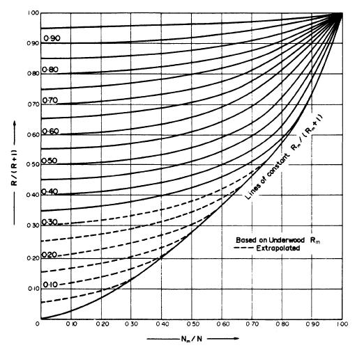
66 Erbar-Maddox 69
67 Feed-point location (Kirkbride equation) 70
68 PLATE EFFICIENCY 71
69 Murphree plate efficiency (Murphree, 1925), defined in terms of the vapour compositions by: where y e is the composition of the vapour that would be in equilibrium with the liquid leaving the plate. The Murphree plate efficiency is the ratio of the actual separation achieved to that which would be achieved in an equilibrium stage. In this definition of efficiency the liquid and the vapour stream are taken to be perfectly mixed. 72
70 Point efficiency (Murphree point efficiency). If the vapour and liquid compositions are taken at a point on the plate, above equation gives the local or point efficiency, E mv. Overall column efficiency. This is sometimes confusingly referred to as the overall plate efficiency. 73
71 74
72 Prediction of plate efficiency And Distillation Design (Sieve Tray) 75
73 Prediction of plate efficiency 76
74 O'Connell's correlation 77
75 78
76 Van Winkle's correlation 79
77 AIChE Method The mass transfer resistances in the vapor and liquid phases are expressed in terms of the number of transfer units, N G and N L. The point efficiency is related to the number of transfer units by the equation: 80
78 81
79 The Murphree efficiency E mv is only equal to the point efficiency E mv if the liquid on the plate is perfectly mixed. On a real plate this will not be so, and to estimate the plate efficiency from the point efficiency some means of estimating the degree of mixing is needed. The dimensionless Peclet number characterizes the degree of mixing in a system. 82
80 A Peclet number of zero indicates perfect mixing and a value of infinite indicates plug flow. For bubble-cap and sieve plates the eddy diffusivity can be estimated from the equation: 83
81 Entrainment In operation some liquid droplets will be entrained and carried up the column by the vapor flow, and this will reduce the actual, operating, efficiency. The dry-plate efficiency can be corrected for the effects of entrainment using the equation proposed by Colburn (1936): where E a = actual plate efficiency, allowing for entrainment, 84
82 APPROXIMATE COLUMN SIZING Plate spacing The overall height of the column will depend on the plate spacing. Plate spacings from 0.15 m (6 in.) to 1 m (36 in.) are normally used. The spacing chosen will depend on the column diameter and operating conditions. Close spacing is used with small-diameter columns, and where head room is restricted; as it will be when a column is installed in a building. For columns above 1 m diameter, plate spacings of 0.3 to 0.6 m will normally be used, and 0.5 m (18 in.) can be taken as an initial estimate. This would be revised, as necessary, when the detailed plate design is made. A larger spacing will be needed between certain plates to accommodate feed and side streams arrangements. 85
83 Column diameter The principal factor that determines the column diameter is the vapor flow-rate. The vapor velocity must be below that which would cause excessive liquid entrainment or a high-pressure drop. The equation given below, which is based on the well-known Souders and Brown equation, Lowenstein (1961), can be used to estimate the maximum allowable superficial vapor velocity, and hence the column area and diameter, 86
84 87
85 PLATE CONTACTORS Cross-flow plates are the most common type of plate contactor used in distillation and absorption columns. In a cross-flow plate the liquid flows across the plate and the vapor up through the plate. The flowing liquid is transferred from plate to plate through vertical channels called "down-comers". A pool of liquid is retained on the plate by an outlet weir. Other types of plate are used which have no down-comers (non-cross-flow plates), the liquid showering down the column through large openings in the plates (sometimes called shower plates). These, and, other proprietary non-cross-flow plates, are used for special purposes, particularly when a low-pressure drop is required. Three principal types of cross-flow tray are used, classified according to the method used to contact the vapor and liquid. 88
86 89
87 1. Sieve plate (perforated plate) This is the simplest type of cross-flow plate. The vapor passes up through perforations in the plate; and the liquid is retained on the plate by the vapor flow. There is no positive vapor liquid seal, and at low flow-rates liquid will "weep" through the holes, reducing the plate efficiency. The perforations are usually small holes, but larger holes and slots are used. 90
88 2. Bubble-cap plates In which the vapor passes up through short pipes, called risers, covered by a cap with a serrated edge, or slots. The bubble-cap plate is the traditional, oldest, type of cross-flow plate, and many different designs have been developed. Standard cap designs would now be specified for most applications. The most significant feature of the bubble-cap plate is that the use of risers ensures that a level of liquid is maintained on the tray at all vapor flow-rates. 91
89 3. Valve plates (floating cap plates) Valve plates are proprietary designs. They are essentially sieve plates with large-diameter holes covered by movable flaps, which lift as the vapor flow increases. As the area for vapor flow varies with the flow-rate, valve plates can operate efficiently at lower flow-rates than sieve plates: the valves closing at low vapor rates. 92
90 Cross-flow trays are also classified according to the number of liquid passes on the plate. The design shown in Figure is a single-pass plate. For low liquid flow rates reverse flow plates are used. In this type the plate is divided by a low central partition, and inlet and outlet down-comers are on the same side of the plate. Multiple-pass plates, in which the liquid stream is sub-divided by using several downcomers, are used for high liquid flow-rates and large diameter columns. A double-pass plate is shown in Figure 93
91 94
92 Selection of plate type The principal factors to consider when comparing the performance of bubble-cap, sieve and valve plates are: cost, capacity, operating range, efficiency and pressure drop. Cost: Bubble-cap plates are appreciably more expensive than sieve or valve plates. The relative cost will depend on the material of construction used; for mild steel the ratios, bubble-cap : valve : sieve, are approximately 3.0: 1.5 :
93 Capacity: There is little difference in the capacity rating of the three types (the diameter of the column required for a given flow-rate); the ranking is sieve, valve, bubble-cap. Operating range: This is the most significant factor. By operating range is meant the range of vapor and liquid rates over which the plate will operate satisfactorily (the stable operating range). Some flexibility will always be required in an operating plant to allow for changes in production rate, and to cover start-up and shut-down conditions. The ratio of the highest to the lowest flow rates is often referred to as the "turn-down" ratio. 96
94 Bubble-cap plates have a positive liquid seal and can therefore operate efficiently at very low vapor rates. Sieve plates rely on the flow of vapor through the holes to hold the liquid on the plate, and cannot operate at very low vapor rates. But, with good design, sieve plates can be designed to give a satisfactory operating range; typically, from 50 per cent to 120 percent of design capacity. Valve plates are intended to give greater flexibility than sieve plates at a lower cost than bubble-caps. Efficiency: The Murphree efficiency of the three types of plate will be virtually the same when operating over their design flow range, and no real distinction can be made between them. 97
95 Pressure drop: The pressure drop over the plates can be an important design consideration, particularly for vacuum columns. The plate pressure drop will depend on the detailed design of the plate but, in general, sieve plates give the lowest pressure drop, followed by valves, with bubble-caps giving the highest. Summary: Sieve plates are the cheapest and are satisfactory for most applications. Valve plates should be considered if the specified turn-down ratio cannot be met with sieve plates. Bubble-caps should only be used where very low vapor (gas) rates have to be handled and a positive liquid seal is essential at all flow-rates. 98
96 Diameter The flooding condition fixes the upper limit of vapor velocity. A high vapor velocity is needed for high plate efficiencies, and the velocity will normally be between 70 to 90 per cent of that which would cause flooding. For design, a value of 80 to 85 per cent of the flooding velocity should be used. The flooding velocity can be estimated from the correlation given by Fair (1961): where u f = flooding vapor velocity, m/s, based on the net column cross-sectional area A n, K 1 = a constant obtained from Figure. 99
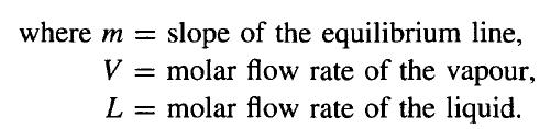
97 The liquid-vapor flow factor F LV in Figure is given by: where L w = liquid mass flow-rate, kg/s, V w = vapour mass flow-rate, kg/s 100
98 The following restrictions apply to the use of Figure: 1. Hole size less than 6.5 mm. Entrainment may be greater with larger hole sizes. 2. Weir height less than 15 per cent of the plate spacing. 3. Non-foaming systems. 4. Hole: active area ratio greater than 0.10; for other ratios apply the following corrections: hole: active area multiply K 1 by Liquid surface tension 0.02 N/m, for other surface tensions σ multiply the value of K 1 by [σ /0.02] 0.2. To calculate the column diameter an estimate of the net area An is required. As a first trial take the down-comer area as 12 per cent of the total, and assume that the hole-active area is 10 per cent. 101
99 Liquid-flow arrangement The choice of plate type (reverse, single pass or multiple pass) will depend on the liquid flow-rate and column diameter. An initial selection can be made using Figure, which has been adapted from a similar figure given by Huang and Hodson (1958). 102
100 Entrainment Entrainment can be estimated from the correlation given by Fair (1961), Figure, which gives the fractional entrainment Ψ (kg/kg gross liquid flow) as a function of the liquidvapor factor F LV with the percentage approach to flooding as a parameter. The percentage flooding is given by: As a rough guide the upper limit of Ψ can be taken as 0.1; below this figure the effect on efficiency will be small. 103
101 104
102 Weep point The lower limit of the operating range occurs when liquid leakage through the plate holes becomes excessive. This is known as the weep point. The vapor velocity at the weep point is the minimum value for stable operation. The hole area must be chosen so that at the lowest operating rate the vapor flow velocity is still well above the weep point. The minimum design vapor velocity is given by: The clear liquid depth is equal to the height of the weir h w plus the depth of the crest of liquid over the weir h ow. 105
103 106
104 Sectional construction 107
105 Downcomers 108
106 109
107 Procedure 1. Calculate the maximum and minimum vapour and liquid flow-rates, for the turn down ratio required. 2. Collect, or estimate, the system physical properties. 3. Select a trial plate spacing. 4. Estimate the column diameter, based on flooding considerations. 5. Decide the liquid flow arrangement. 6. Make a trial plate layout: downcomer area, active area, hole area, hole size, weir height. 7. Check the weeping rate, if unsatisfactory return to step Check the plate pressure drop, if too high return to step Check downcomer back-up, if too high return to step 6 or Decide plate layout details: calming zones, unperforated areas. Check hole pitch, if unsatisfactory return to step Recalculate the percentage flooding based on chosen column diameter. 12.Check entrainment, if too high return to step Optimise design: repeat steps 3 to 12 to find smallest diameter and plate spacing acceptable (lowest cost). 14.Finalise design: draw up the plate specification and sketch the layout. 110
108 Plate areas 111
109 Weir liquid crest The height of the liquid crest over the weir can be estimated using the Francis weir Formula. For a segmental downcomer this can be written as: 112
110 Weir dimensions: Weir height: The height of the weir determines the volume of liquid on the plate and is an important factor in determining the plate efficiency. A high weir will increase the plate efficiency but at the expense of a higher plate pressure drop. For columns operating above atmospheric pressure the weir heights will normally be between 40 mm to 90 mm (1.5 to 3.5 in.); 40 to 50 mm is recommended. For vacuum operation lower weir heights are used to reduce the pressure drop; 6 to 12 mm (1/4 to ½ in.) is recommended. 113
111 Inlet weirs: Inlet weirs, or recessed pans, are sometimes used to improve the distribution of liquid across the plate; but are seldom needed with segmental downcorners. Weir length With segmental downcorners the length of the weir fixes the area of the downcomer. The chord length will normally be between 0.6 to 0.85 of the column diameter. A good initial value to use is 0.77, equivalent to a downcomer area of 12 per cent. The relationship between weir length and downcomer area is given in Figure. For double-pass plates the width of the central downcomer is normally mm (8-10 in.). 114
112 115
113 Perforated area The area available for perforation will be reduced by the obstruction caused by structural members (the support rings and beams), and by the use of calming zones. Calming zones are unperforated strips of plate at the inlet and outlet sides of the plate. The width of each zone is usually made the same; recommended values are: below 1.5 m diameter, 75 mm; above, 100 mm. The width of the support ring for sectional plates will normally be 50 to 75 mm; the support ring should not extend into the downcomer area. A strip of unperforated plate will be left round the edge of cartridge-type trays to stiffen the plate. The unperforated area can be calculated from the plate geometry. The relationship between the weir chord length, chord height and the angle subtended by the chord is given in Figure 116
114 117
115 Hole size The hole sizes used vary from 2.5 to 12 mm; 5 mm is the preferred size. Larger holes are occasionally used for fouling systems. The holes are drilled or punched. Punching is cheaper, but the minimum size of hole that can be punched will depend on the plate thickness, For carbon steel, hole sizes approximately equal to the plate thickness can be punched, but for stainless steel the minimum hole size that can be punched is about twice the plate thickness. Typical plate thicknesses used are: 5 mm (3/16 in.) for carbon steel, and 3 mm (12 gauge) for stainless steel. When punched plates are used they should be installed with the direction of punching upward. Punching forms a slight nozzle, and reversing the plate will increase the pressure drop. 118
116 Hole pitch The hole pitch (distance between the hole centres) l p should not be less than 2.0 hole diameters, and the normal range will be 2.5 to 4.0 diameters. Within this range the pitch can be selected to give the number of active holes required for the total hole area specified. Square and equilateral triangular patterns are used; triangular is preferred. The total hole area as a fraction of the perforated area A p is given by the following expression, for an equilateral triangular pitch: 119
117 120
118 Hydraulic gradient The hydraulic gradient is the difference in liquid level needed to drive the liquid flow across the plate. On sieve plates, unlike bubble-cap plates, the resistance to liquid flow will be small, and the hydraulic gradient is usually ignored in sieve-plate design. It can be significant in vacuum operation, as with the low weir heights used the hydraulic gradient can be a significant fraction of the total liquid depth. Methods for estimating the hydraulic gradient are given by Fair (1963). 121
119 Liquid throw The liquid throw is the horizontal distance travelled by the liquid stream flowing over the downcomer weir. It is only an important consideration in the design of multiplepass plates. Bolles (1963) gives a method for estimating the liquid throw. Plate pressure drop The pressure drop over the plates is an important design consideration. There are two main sources of pressure loss: that due to vapour flow through the holes (an orifice loss), and that due to the static head of liquid on the plate. 122
120 A simple additive model is normally used to predict the total pressure drop. The total is taken as the sum of the pressure drop calculated for the flow of vapour through the dry plate (the dry plate drop h d ); the head of clear liquid on the plate (h w + h ow ) and a term to account for other, minor, sources of pressure loss, the so-called residual loss h r. The residual loss is the difference between the observed experimental pressure drop and the simple sum of the dry-plate drop and the clear-liquid height. It accounts for the two effects: the energy to form the vapour bubbles and the fact that on an operating plate the liquid head will not be clear liquid but a head of "aerated" liquid froth, and the froth density and height will be different from that of the clear liquid. It is convenient to express the pressure drops in terms of millimetres of liquid. In pressure units: 123
121 Dry plate drop Residual head Total drop 124
122 125
123 Downcomer design [back-up] The downcomer area and plate spacing must be such that the level of the liquid and froth in the downcomer is well below the top of the outlet weir on the plate above. If the level rises above the outlet weir the column will flood. The back-up of liquid in the downcomer is caused by the pressure drop over the plate (the downcomer in effect forms one leg of a U-tube) and the resistance to flow in the downcomer itself. In terms of clear liquid the downcomer back-up is given by: 126
124 127
125 Froth height To predict the height of "aerated" liquid on the plate, and the height of froth in the downcomer, some means of estimating the froth density is required. The density of the "aerated" liquid will normally be between 0.4 to 0.7 times that of the clear liquid. A number of correlations have been proposed for estimating froth density as a function of the vapour flow-rate and the liquid physical properties. However, none is particularly reliable, and for design purposes it is usually satisfactory to assume an average value of 0.5 of the liquid density. This value is also taken as the mean density of the fluid in the downcomer; which means that for safe design the clear liquid back-up, calculated from equation, should not exceed half the plate spacing l t to avoid flooding. 128
126 129
Liquid -Vapor. Contacting columns
 Liquid -Vapor * Contacting columns Distillation Column Design The design of a distillation column can be divided into the following steps: 1. Specify the degree of separation required: set product specifications.
DISTILLATION POINTS TO REMEMBER
 DISTILLATION POINTS TO REMEMBER 1. Distillation columns carry out physical separation of liquid chemical components from a mixture by a. A combination of transfer of heat energy (to vaporize lighter components)
Distillation Design The McCabe-Thiele Method
 Distillation Design The McCabe-Thiele Method Distiller diagam Introduction Using rigorous tray-by-tray calculations l is time consuming, and is often unnecessary. One quick method of estimation i for number
CHE 306 Stagewise Operations
 CHE 306 Stagewise Operations Fall 2010 Introduction ti to Column Distillation Instructor: Dr. Housam Binous KFUPM, Dhahran 1 Over 90% of separations are done using distillation Over 40 000 distillation
Figure Vapor-liquid equilibrium for a binary mixture. The dashed lines show the equilibrium compositions.
 Another way to view this problem is to say that the final volume contains V m 3 of alcohol at 5.93 kpa and 20 C V m 3 of air at 94.07 kpa and 20 C V m 3 of air plus alcohol at 100 kpa and 20 C Thus, the
Manual for continuous distillation
 Manual for continuous distillation 1. Week 1: Objectives: Run the column at total reflux. When steady state is reached, take the sample from the top and bottom of the column in order to determine the overall
PURE SUBSTANCE. Nitrogen and gaseous air are pure substances.
 CLASS Third Units PURE SUBSTANCE Pure substance: A substance that has a fixed chemical composition throughout. Air is a mixture of several gases, but it is considered to be a pure substance. Nitrogen and
Countercurrent Stagewise Operations Equilibrium Stage Number of Actual Stages Definition of The Design Problem...
 Countercurrent Stagewise Operations All rights reserved, Armando B. Corripio 2013 Contents Countercurrent Stagewise Operations... 1 1 Equilibrium Stage... 4 1.1 Number of Actual Stages.... 5 2 Definition
ERTC PETROCHEMICAL Conference 20 st -22 nd February 2002, Amsterdam, The Netherlands
 Reprint from Presentation at ERTC PETROCHEMICAL Conference 20 st -22 nd February 2002, Amsterdam, The Netherlands and ARTC PETROCHEMICAL Conference 11 th 13 th March 2002, Bangkok, Thailand Sulzer Chemtech,
CHE 4115 Chemical Processes Laboratory 2 Experiment 1. Batch Distillation
 CHE 4115 Chemical Processes Laboratory 2 Experiment 1 Batch Distillation BACKGROUND Distillation is one of the most commonly used unit operations in chemical engineering. In general, a distillation operation
Module # 8 DISTILLATION AND ABSORPTION COLUMN
 Module # 8 MECHANICAL DESIGN OF MASS TRANSFER COLUMN: DESIGN OF DISTILLATION AND ABSORPTION COLUMN 1. Design and construction features of column internals 1.1. Plate construction 1.2. Downcomer details
Efficiency and Control of a Heat Integrated Distillation Column (HIDiC)
") DELFT UNIVERSITY OF TECHNOLOGY, DEPARTMENT OF PROCESS AND ENERGY Efficiency and Control of a Heat Integrated Distillation Column (HIDiC) MSc Thesis Anne Traa 7/25/2010 Graduation Committee: Prof. dr. ir.
DELFT UNIVERSITY OF TECHNOLOGY, DEPARTMENT OF PROCESS AND ENERGY Efficiency and Control of a Heat Integrated Distillation Column (HIDiC) MSc Thesis Anne Traa 7/25/2010 Graduation Committee: Prof. dr. ir.
THE WAY THE VENTURI AND ORIFICES WORK
 Manual M000 rev0 03/00 THE WAY THE VENTURI AND ORIFICES WORK CHAPTER All industrial combustion systems are made up of 3 main parts: ) The mixer which mixes fuel gas with combustion air in the correct ratio
Removing nitrogen. Nitrogen rejection applications can be divided into two categories
 Removing nitrogen Doug MacKenzie, Ilie Cheta and Darryl Burns, Gas Liquids Engineering, Canada, present a comparative study of four nitrogen removal processes. Nitrogen rejection applications can be divided
Chapter 13 Gases, Vapors, Liquids, and Solids
 Chapter 13 Gases, Vapors, Liquids, and Solids Property is meaning any measurable characteristic of a substance, such as pressure, volume, or temperature, or a characteristic that can be calculated or deduced,
Gerald D. Anderson. Education Technical Specialist
 Gerald D. Anderson Education Technical Specialist The factors which influence selection of equipment for a liquid level control loop interact significantly. Analyses of these factors and their interactions
Thermodynamics ERT 206 Properties of Pure Substance HANNA ILYANI ZULHAIMI
 Thermodynamics ERT 206 Properties of Pure Substance HANNA ILYANI ZULHAIMI Outline: Pure Substance Phases of pure substance Phase change process of pure substance Saturation temperature and saturation pressure
PHYS 101 Previous Exam Problems
 PHYS 101 Previous Exam Problems CHAPTER 14 Fluids Fluids at rest pressure vs. depth Pascal s principle Archimedes s principle Buoynat forces Fluids in motion: Continuity & Bernoulli equations 1. How deep
Basic concepts of phase behavior
 Basic concepts of phase behavior 1) Single component system. Ethane is taken as an example for single component system. Ethane exists as gas phase at ordinary conditions. At other than ordinary conditions,
Chem 110 General Principles of Chemistry
 CHEM110 Worksheet - Gases Chem 110 General Principles of Chemistry Chapter 9 Gases (pages 337-373) In this chapter we - first contrast gases with liquids and solids and then discuss gas pressure. - review
Another convenient term is gauge pressure, which is a pressure measured above barometric pressure.
 VACUUM Theory and Applications Vacuum may be defined as the complete emptiness of a given volume. It is impossible to obtain a perfect vacuum, but it is possible to obtain a level of vacuum, defined as
Applied Fluid Mechanics
 Applied Fluid Mechanics 1. The Nature of Fluid and the Study of Fluid Mechanics 2. Viscosity of Fluid 3. Pressure Measurement 4. Forces Due to Static Fluid 5. Buoyancy and Stability 6. Flow of Fluid and
EDUCTOR. principle of operation
 EDUCTOR principle of operation condensate and mixing eductor s are designed to mix two liquids intimately in various proportions in operations where the pressure liquid is the greater proportion of the
Chapter 13 Fluids. Copyright 2009 Pearson Education, Inc.
 Chapter 13 Fluids Phases of Matter Density and Specific Gravity Pressure in Fluids Atmospheric Pressure and Gauge Pressure Pascal s Principle Units of Chapter 13 Measurement of Pressure; Gauges and the
The water supply for a hydroelectric plant is a reservoir with a large surface area. An outlet pipe takes the water to a turbine.
 Fluids 1a. [1 mark] The water supply for a hydroelectric plant is a reservoir with a large surface area. An outlet pipe takes the water to a turbine. State the difference in terms of the velocity of the
Ch. 11 Mass transfer principles
 Transport of chemical species in solid, liquid, or gas mixture Transport driven by composition gradient, similar to temperature gradients driving heat transport We will look at two mass transport mechanisms,
LOW PRESSURE EFFUSION OF GASES adapted by Luke Hanley and Mike Trenary
 ADH 1/7/014 LOW PRESSURE EFFUSION OF GASES adapted by Luke Hanley and Mike Trenary This experiment will introduce you to the kinetic properties of low-pressure gases. You will make observations on the
Process Dynamics, Operations, and Control Lecture Notes - 20
 Lesson 0. Control valves 0.0 Context Controller output is a signal that varies between 0 and 100%. Putting this signal to use requires a final control element, a device that responds to the controller
Free Surface Flow Simulation with ACUSIM in the Water Industry
 Free Surface Flow Simulation with ACUSIM in the Water Industry Tuan Ta Research Scientist, Innovation, Thames Water Kempton Water Treatment Works, Innovation, Feltham Hill Road, Hanworth, TW13 6XH, UK.
Use equation for the cylindrical section and equation or for the ends.
 Solution 13.1 See section 13.3.4, equations 13.7 to 13.18 Solution 13.2 Use equation 13.34. (a) rigid constant C = 0.43 (b) free to rotate, C = 0.56 Solution 13.3 See section 13.5.1 Use equation 13.39
3 1 PRESSURE. This is illustrated in Fig. 3 3.
 P = 3 psi 66 FLUID MECHANICS 150 pounds A feet = 50 in P = 6 psi P = s W 150 lbf n = = 50 in = 3 psi A feet FIGURE 3 1 The normal stress (or pressure ) on the feet of a chubby person is much greater than
DSTWU A Shortcut Distillation Model in Aspen Plus V8.0
 DSTWU A Shortcut Distillation Model in Aspen Plus V8.0 1. Lesson Objectives Learn how to use DSTWU to start distillation column design. Learn the strengths and limitations of shortcut methods 2. Prerequisites
PETROLEUM & GAS PROCESSING TECHNOLOGY (PTT 365) SEPARATION OF PRODUCED FLUID
 SEPARATION OF PRODUCED FLUID") PETROLEUM & GAS PROCESSING TECHNOLOGY (PTT 365) SEPARATION OF PRODUCED FLUID Miss Nur Izzati Bte Iberahim Introduction Well effluents flowing from producing wells come out in two phases: vapor and liquid
PETROLEUM & GAS PROCESSING TECHNOLOGY (PTT 365) SEPARATION OF PRODUCED FLUID Miss Nur Izzati Bte Iberahim Introduction Well effluents flowing from producing wells come out in two phases: vapor and liquid
Chapter 2: Pure Substances a) Phase Change, Property Tables and Diagrams
 Phase Change, Property Tables and Diagrams") Chapter 2: Pure Substances a) Phase Change, Property Tables and Diagrams In this chapter we consider the property values and relationships of a pure substance (such as water) which can exist in three phases
Chapter 2: Pure Substances a) Phase Change, Property Tables and Diagrams In this chapter we consider the property values and relationships of a pure substance (such as water) which can exist in three phases
Generating Calibration Gas Standards
 Technical Note 1001 Metronics Inc. Generating Calibration Gas Standards with Dynacal Permeation Devices Permeation devices provide an excellent method of producing known gas concentrations in the PPM and
OIL AND GAS INDUSTRY
 This case study discusses the sizing of a coalescer filter and demonstrates its fouling life cycle analysis using a Flownex model which implements two new pressure loss components: - A rated pressure loss
OIL SUPPLY SYSTEMS ABOVE 45kW OUTPUT 4.1 Oil Supply
 OIL SUPPLY SYSTEMS ABOVE 45kW OUTPUT 4.1 Oil Supply 4.1.1 General The primary function of a system for handling fuel oil is to transfer oil from the storage tank to the oil burner at specified conditions
Chapter 15 Fluids. Copyright 2010 Pearson Education, Inc.
 Chapter 15 Fluids Density Units of Chapter 15 Pressure Static Equilibrium in Fluids: Pressure and Depth Archimedes Principle and Buoyancy Applications of Archimedes Principle Fluid Flow and Continuity
1. The principle of fluid pressure that is used in hydraulic brakes or lifts is that:
 University Physics (Prof. David Flory) Chapt_15 Thursday, November 15, 2007 Page 1 Name: Date: 1. The principle of fluid pressure that is used in hydraulic brakes or lifts is that: A) pressure is the same
Old-Exam.Questions-Ch-14 T072 T071
 Old-Exam.Questions-Ch-14 T072 Q23. Water is pumped out of a swimming pool at a speed of 5.0 m/s through a uniform hose of radius 1.0 cm. Find the mass of water pumped out of the pool in one minute. (Density
Air Eliminators and Combination Air Eliminators Strainers
 Description Air Eliminators and Combination Air Eliminator Strainers are designed to provide separation, elimination and prevention of air in piping systems for a variety of installations and conditions.
ENGR 292 Fluids and Thermodynamics
 ENGR 292 Fluids and Thermodynamics Scott Li, Ph.D., P.Eng. Mechanical Engineering Technology Camosun College Pure Substances Phase-Change Process of Pure Substances Specific Volume Saturation Temperature
Optimizing Effective Absorption during Wet Natural Gas Dehydration by Tri Ethylene Glycol
 IOSR Journal of Applied Chemistry (IOSRJAC) ISSN : 2278-5736 Volume 2, Issue 2 (Sep-Oct. 212), PP 1-6 Optimizing Effective Absorption during Wet Natural Gas Dehydration by Tri Ethylene Glycol Khan, Mohd
4.1 Why is the Equilibrium Diameter Important?
 Chapter 4 Equilibrium Calculations 4.1 Why is the Equilibrium Diameter Important? The model described in Chapter 2 provides information on the thermodynamic state of the system and the droplet size distribution.
CALCULATING THE SPEED OF SOUND IN NATURAL GAS USING AGA REPORT NO Walnut Lake Rd th Street Houston TX Garner, IA 50438
 CALCULATING THE SPEED OF SOUND IN NATURAL GAS USING AGA REPORT NO. 10 Jerry Paul Smith Joel Clancy JPS Measurement Consultants, Inc Colorado Engineering Experiment Station, Inc (CEESI) 13002 Walnut Lake
Chapter 15 Fluid. Density
 Density Chapter 15 Fluid Pressure Static Equilibrium in Fluids: Pressure and Depth Archimedes Principle and Buoyancy Applications of Archimedes Principle By Dr. Weining man 1 Units of Chapter 15 Fluid
Irrigation &Hydraulics Department lb / ft to kg/lit.
 CAIRO UNIVERSITY FLUID MECHANICS Faculty of Engineering nd Year CIVIL ENG. Irrigation &Hydraulics Department 010-011 1. FLUID PROPERTIES 1. Identify the dimensions and units for the following engineering
Fit for Purpose Compositional Input for Allocation Using Equations of State Thomas Hurstell, Letton Hall Group
 UPM 15030 Fit for Purpose al Input for Allocation Using Equations of State Thomas Hurstell, Letton Hall Group Abstract Methods are presented to develop compositional input for use in allocation systems
End of Chapter Exercises
 End of Chapter Exercises Exercises 1 12 are conceptual questions that are designed to see if you have understood the main concepts of the chapter. 1. While on an airplane, you take a drink from your water
Chapter 13 Fluids. Copyright 2009 Pearson Education, Inc.
 Chapter 13 Fluids Phases of Matter Density and Specific Gravity Pressure in Fluids Atmospheric Pressure and Gauge Pressure Pascal s Principle Units of Chapter 13 Measurement of Pressure; Gauges and the
Micro Channel Recuperator for a Reverse Brayton Cycle Cryocooler
 Micro Channel Recuperator for a Reverse Brayton Cycle Cryocooler C. Becnel, J. Lagrone, and K. Kelly Mezzo Technologies Baton Rouge, LA USA 70806 ABSTRACT The Missile Defense Agency has supported a research
LOW PRESSURE EFFUSION OF GASES revised by Igor Bolotin 03/05/12
 LOW PRESSURE EFFUSION OF GASES revised by Igor Bolotin 03/05/ This experiment will introduce you to the kinetic properties of low-pressure gases. You will make observations on the rates with which selected
CHAPTER 2 EXPERIMENTAL SETUP AND PROCEDURE
 22 CHAPTER 2 EXPERIMENTAL SETUP AND PROCEDURE 2.1 EXPERIMENTAL COLUMN All the experiments were carried out in an internal loop airlift fluidized bed and combined loop fluidized bed (an external down comer
Felles Lab: Distillation Columns
 Felles Lab: Distillation Columns Separation September, 2012 Contents 1. Objectives... 2 2. Required Knowledge/Support Literature... 3 3. Brief Theory... 5 3.1. Definitions... 5 4. Equipment... 7 5. Planning
THE INNER WORKINGS OF A SIPHON Jacques Chaurette p. eng. January 2003
 THE INNER WORKINGS OF A SIPHON Jacques Chaurette p. eng. www.lightmypump.com January 2003 Synopsis The objective of this article is to explain how a siphon works. The difference between low pressure, atmospheric
Simulation and Economic Optimization of Vapor Recompression Configuration for Partial CO2 capture
 Simulation and Economic Optimization of Vapor Recompression Configuration for Partial CO2 capture Lars Erik Øi 1 Erik Sundbø 1 Hassan Ali 1 1 Department of and Process, Energy and Environmental Technology,
AP Physics B Ch 10 Fluids. MULTIPLE CHOICE. Choose the one alternative that best completes the statement or answers the question.
 Name: Period: Date: AP Physics B Ch 10 Fluids 1) The three common phases of matter are A) solid, liquid, and vapor. B) solid, plasma, and gas. C) condensate, plasma, and gas. D) solid, liquid, and gas.
Development of High-speed Gas Dissolution Device
 Development of High-speed Gas Dissolution Device Yoichi Nakano*, Atsushi Suehiro**, Tetsuhiko Fujisato***, Jun Ma**** Kesayoshi Hadano****, Masayuki Fukagawa***** *Ube National College of Technology, Tokiwadai
Previous Page 5.6 TRANSFER UNITS
 Previous Page 5.6 TRANSFER UNITS Computationally, distillation columns are treated as staged devices, even though in some designs they function as countercurrent contactors such as packed columns. Accordingly,
Lecture Outline Chapter 15. Physics, 4 th Edition James S. Walker. Copyright 2010 Pearson Education, Inc.
 Lecture Outline Chapter 15 Physics, 4 th Edition James S. Walker Chapter 15 Fluids Density Units of Chapter 15 Pressure Static Equilibrium in Fluids: Pressure and Depth Archimedes Principle and Buoyancy
Assistant Lecturer Anees Kadhum AL Saadi
 Pressure Variation with Depth Pressure in a static fluid does not change in the horizontal direction as the horizontal forces balance each other out. However, pressure in a static fluid does change with
Transient Analyses In Relief Systems
 Transient Analyses In Relief Systems Dirk Deboer, Brady Haneman and Quoc-Khanh Tran Kaiser Engineers Pty Ltd ABSTRACT Analyses of pressure relief systems are concerned with transient process disturbances
1. A pure substance has a specific volume of 0.08 L/mol at a pressure of 3 atm and 298 K. The substance is most likely:
 Name: September 19, 2014 EXAM 1 P a g e 1 1. A pure substance has a specific volume of 0.08 L/mol at a pressure of 3 atm and 298 K. The substance is most likely: a. Liquid b. Gas c. Supercritical Fluid
End of Chapter Exercises
 End of Chapter Exercises Exercises 1 12 are conceptual questions that are designed to see if you have understood the main concepts of the chapter. 1. While on an airplane, you take a drink from your water
differential pressure regulating valve - threaded
 140-142 differential pressure regulating valve - threaded Introduction Differential pressure regulating valves (DPRV) maintain the differential pressure across a circuit or sub-branch at a set differential
Gas Pressure. Pressure is the force exerted per unit area by gas molecules as they strike the surfaces around them.
 Chapter 5 Gases Gas Gases are composed of particles that are moving around very fast in their container(s). These particles moves in straight lines until they collides with either the container wall or
Inprocess Operator Training Programme
 2016 Inprocess Operator Training Programme ABSORPTION COLUMN These exercises are intended to provide an understanding of absorption columns and the fundamental principles they use to eliminate pollutants
Process Nature of Process
 AP Physics Free Response Practice Thermodynamics 1983B4. The pv-diagram above represents the states of an ideal gas during one cycle of operation of a reversible heat engine. The cycle consists of the
Third measurement MEASUREMENT OF PRESSURE
 1. Pressure gauges using liquids Third measurement MEASUREMENT OF PRESSURE U tube manometers are the simplest instruments to measure pressure with. In Fig.22 there can be seen three kinds of U tube manometers
Chapter 10: Gases. Characteristics of Gases
 Chapter 10: Gases Learning Outcomes: Calculate pressure and convert between pressure units with an emphasis on torr and atmospheres. Calculate P, V, n, or T using the ideal-gas equation. Explain how the
Mass Split of Two-Phase-Flow
 Mass Split of Two-Phase-Flow The split of two-phase-flow at horizontal side-t-junctions in unbalanced pipe systems for clean extinguishing agents Speaker: Gudrun Fay Minimax 2010 2013 Content 1. Applications
Interchangeability Criteria.
 Interchangeability Criteria. A substitute gas should burn satisfactorily with negligible change in burner performance on all types of burners without the need for special adjustment. The important requirements
SRI Jigger Tubes System
 SRI Jigger Tubes System Design, Installation and Commissioning Manual (Abbreviated Version) INDEX This manual details how the SRI Jigger Tubes System can be tailored to suit the needs of a variety of vacuum
Application Worksheet
 Application Worksheet All dimensions are nominal. Dimensions in [ ] are in millimeters. Service Conditions Medium Through Valve: Required C v : Temperature Maximum: Minimum: Normal: Flow Maximum: Minimum:
Bioreactor System ERT 314. Sidang /2011
 Bioreactor System ERT 314 Sidang 1 2010/2011 Chapter 2:Types of Bioreactors Week 4 Flow Patterns in Agitated Tanks The flow pattern in an agitated tank depends on the impeller design, the properties of
Optimal Operation of Dividing Wall Column using Enhanced Active Vapor Distributor
 A publication of CHEMICAL ENGINEERING TRANSACTIONS VOL. 69, 2018 Guest Editors: Elisabetta Brunazzi, Eva Sorensen Copyright 2018, AIDIC Servizi S.r.l. ISBN 978-88-95608-66-2; ISSN 2283-9216 The Italian
Hours / 100 Marks Seat No.
 17421 21415 3 Hours / 100 Marks Seat No. Instructions : (1) All Questions are compulsory. (2) Answer each next main Question on a new page. (3) Illustrate your answers with neat sketches wherever necessary.
Analysis and Modeling of Vapor Recompressive Distillation Using ASPEN-HYSYS
 Computer Science Journal of Moldova, vol.19, no.2(56), 2011 Analysis and Modeling of Vapor Recompressive Distillation Using ASPEN-HYSYS Cinthujaa C. Sivanantha, Gennaro J. Maffia Abstract HYSYS process
Practical Guide. By Steven T. Taylor, P.E., Member ASHRAE
 ractical Guide The following article was published in ASHRAE Journal, March 2003. Copyright 2003 American Society of Heating, Refrigerating and Air- Conditioning Engineers, Inc. It is presented for educational
2. Determine how the mass transfer rate is affected by gas flow rate and liquid flow rate.
 Goals for Gas Absorption Experiment: 1. Evaluate the performance of packed gas-liquid absorption tower. 2. Determine how the mass transfer rate is affected by gas flow rate and liquid flow rate. 3. Consider
Air Eliminator Series
 Air Eliminator Series Air Separation Equipment FILE NO: 9-1 DATE: August 2010 SUPERSEDES: 9-1 DATE: January 2009 Air Eliminator Series Air Separation Equipment Modern sealed heating and cooling systems
OPENINGS AND REINFORCEMENTS 26
 ASME BPVC.VIII.1-2015 UG-35.2 UG-36 (4) It is recognized that it is impractical to write requirements to cover the multiplicity of devices used for quick access, or to prevent negligent operation or the
The Ideal Gas Constant
 Chem 2115 Experiment # 8 The Ideal Gas Constant OBJECTIVE: This experiment is designed to provide experience in gas handling methods and experimental insight into the relationships between pressure, volume,
Armfield Distillation Column Operation Guidelines
 Armfield Distillation Column Operation Guidelines 11-2016 R.Cox Safety SAFETY GLASSES ARE REQUIRED WHEN OPERATING THE DISTILLATION COLUMN Wear gloves when mixing alcohol feedstock The column will become
FLOMIXERS SELECTION DATA ALL GASES
 MODEL: 2301 Revision: 0 BULLETIN 2301-2311 FLOMIXERS are proportional mixing devices that utilize the energy of a stream of air at pressures up to several pounds to (1) entrain a combustible gas, and (2)
Title: Choosing the right nitrogen rejection scheme
 Title: Choosing the right nitrogen rejection scheme Authors: Nicolas Chantant, Paul Terrien, Sylvain Gérard (Air Liquide Global E&C Solutions) Abstract: Nitrogen Rejection Units (NRU) are used to extract
Experimental Analysis on Vortex Tube Refrigerator Using Different Conical Valve Angles
 International Journal of Engineering Research and Development e-issn: 7-067X, p-issn: 7-00X, www.ijerd.com Volume 3, Issue 4 (August ), PP. 33-39 Experimental Analysis on Vortex Tube Refrigerator Using
A NEW PROCESS FOR IMPROVED LIQUEFACTION EFFICIENCY
 WHITE PAPER A NEW PROCESS FOR IMPROVED LIQUEFACTION EFFICIENCY Author(s): Adam Jones and Grant Johnson, Costain Natural Resources First published: GPAE, September 2014 www.costain.com A New Process for
09 - Choosing /sizing a cylinder and valve
 - Choosing /sizing a cylinder and valve - Pipe flow resistence - Valve sizing - Cylinder sizing LII PIPE FLOW RESISTENCE Flow rate Qn Flow rate is calculated as the volume at normal conditions ( atmospheric
Disc diffuser ELASTOX -T
 Pioneering for You Series documentation version 12/2016 2 Application ƒƒfor fine-bubble compressed air aeration within the biological treatment stage ƒƒdepending on application and basin geometry: Use
RESISTANCE OF COMPACTED ASPHALT MIXTURE TO MOISTURE INDUCED DAMAGE (Kansas Test Method KT-56)
") 5.9.56 RESISTANCE OF COMPACTED ASPHALT MIXTURE TO MOISTURE INDUCED DAMAGE (Kansas Test Method ) 1. SCOPE This test covers preparation of specimens and measurement of the change of tensile strength resulting
5.9.56 RESISTANCE OF COMPACTED ASPHALT MIXTURE TO MOISTURE INDUCED DAMAGE (Kansas Test Method ) 1. SCOPE This test covers preparation of specimens and measurement of the change of tensile strength resulting
The activated sludge process
 The activated sludge process Most wastewater treatment plants are using the activated sludge process. The heart of such a process mainly consists of an aeration tank, a sedimentation tank or clarifier
Flow and Mixing in the Liquid between Bubbles
 Excerpt from the Proceedings of the COMSOL Conference 2009 Boston Flow and Mixing in the Liquid between Bubbles Bruce A. Finlayson, Professor Emeritus of Chemical Engineering Department of Chemical Engineering,
(Refer Slide Time: 2:16)
") Fluid Machines. Professor Sankar Kumar Som. Department Of Mechanical Engineering. Indian Institute Of Technology Kharagpur. Lecture-23. Diffuser and Cavitation. Good morning and welcome you all to this
Fluid Machines. Professor Sankar Kumar Som. Department Of Mechanical Engineering. Indian Institute Of Technology Kharagpur. Lecture-23. Diffuser and Cavitation. Good morning and welcome you all to this
CTB3365x Introduction to Water Treatment
 CTB3365x Introduction to Water Treatment D4b Aeration Doris van Halem Did you know that there are not just gasses in your glass of sparkling coke, but also in the tap water you drink? Welcome to the water
Flow in a shock tube
 Flow in a shock tube April 30, 05 Summary In the lab the shock Mach number as well as the Mach number downstream the moving shock are determined for different pressure ratios between the high and low pressure
STRUCTURED PACKING FLOODING: ITS MEASUREMENT AND PREDICTION
 STRUCTURED PACKING FLOODING: ITS MEASUREMENT AND PREDICTION M. J. Lockett, R. A. Victor, J. F. Billingham Praxair, Inc., PO Box 44, Tonawanda, NY 14151-0044, USA. E-mail: Mike_Lockett@Praxair.com A cryogenic
SUMMARY PROBLEMS CAUSED BY BACKFLOW IN PIPE SYSTEMS.
 Page 1 of 11 SUMMARY There are many problems derived from a reverse flow in a piping system. A solution presented in this paper is the WaStop inline check valve. The paper aims to explain some of the important
Structure of Mechanically Agitated Gas-Liquid Contactors
 Structure of Mechanically Agitated Gas-Liquid Contactors 5 2 Structure of Mechanically Agitated Gas-Liquid Contactors 2.1 The vessel geometry The most commonly adopted geometry of a stirred gas-liquid
Pressure reducing valves Index
 Index General information page Introduction 506 General introduction 507 for a steam plant 509 Product information BSP thread page Brass 510 ; BSP female thread 511 ; BSP male thread 513 Stainless steel