Chemical Injection Technologies Installation/Service Bulletin
|
|
|
- Emory Cain
- 6 years ago
- Views:
Transcription
1 Bulletin 4002 Chemical Injection Technologies Installation/Service Bulletin SUPERIOR Series CL-16/26/56 Automatic Switchover Gas Chlorinator - Installation & Operation IMPORTANT!! READ THESE PRECAUTIONS BEFORE PROCEEDING!!! They are very important for your personal safety, and for proper chlorinator operation. 1. Read these precautions and all related instructions thoroughly and follow them carefully. If you do not understand any of the information, call your local SUPERIOR supplier or Chemical Injection Technologies, Inc. Do not attempt to install or operate any gas chlorination/sulfonation equipment unless you are properly trained. 2. Read the "CHLORINATOR CYLINDER CHANGING PROCEDURE" card supplied with your chlorinator, and be certain you fully understand the information presented on the card. If you do not have the card, contact your local SUPERIOR supplier or Chemical Injection Technologies, Inc. and we will supply one. 3. Make certain all required safety equipment is in place and operational. 4. When performing any maintenance or changing cylinders, Chemical Injection Technologies, Inc. strongly recommends that a gas mask (a pressure-demand type air pack is strongly recommended) should be available in the immediate area of the chlorination equipment and all operating personnel should be properly trained in its use. 5. Chlorine gas or the fumes from chlorine solutions can be lethal in large enough doses. Therefore, you should always have a co-worker observe from a safe location when you are working on any type of chlorination equipment. 6. Avoid breathing the gas or fumes of chlorine solutions and avoid contact with your skin. Work only in a well-ventilated area. Chlorine will bleach clothing. 7. Before working on the chlorination system, make certain that the cylinder valve is shut off. If it seems to be shut off already, open it one quarter turn and immediately close it to make certain that the valve is not frozen in the open position. If the valve stem does not turn easily, you may use the heel of your hand to tap the cylinder wrench. Never use a hammer or other tool to force the valve stem. If you cannot turn the cylinder valve in either direction, always assume it is open. BE POSITIVE THIS VALVE IS CLOSED BEFORE LOOSENING THE CHLORINATOR MOUNTING YOKE OR VALVE CAP. If you are not sure, call your chlorine supplier. 8. Do not use wrenches larger than the standard cylinder wrench and do not hit the wrench with a heavy object to open or close the valve. 9. Do not re-use lead gaskets. THIS IS VERY IMPORTANT! Do not re-use a lead gasket because used gaskets will not properly seal the chlorinator/cylinder connection and will cause leaks. 10. Use only lead gaskets. Other types may contract with temperature variations resulting in the escape of gas. 11. Check for chlorine gas leaks every time the chlorinator is connected or remounted onto the cylinder. Using a plastic squeeze bottle of strong ammonia, approximately a full, squeeze fumes under the lead gasket connection and around the cylinder valve bonnet and valve stem. A piece of rag or paper towel wetted with ammonia may also be held under the connection. Do not pour ammonia onto the valve or connection. A chlorine or Sulfur Dioxide leak will create "smokelike" fumes similar to cigarette smoke. Correct the leak before proceeding. 12. Open the cylinder valve ¼ to ½ turn only, and leave the wrench on the cylinder valve when it is open. 13. The rate valve is not a shut-off valve. To shut-off chlorine, use the chlorine cylinder valve. 14. Always use safety chains or clamps to secure the chlorine cylinders so they may not be accidentally tipped over. Protective hoods and valve caps must be in place whenever cylinders are not in use. NOTE: These instructions are also applicable to SUPERIOR Gas Sulfonators. Just substitute "sulfonator" wherever the word "chlorinator" appears and substitute "sulfur dioxide" wherever "chlorine" appears. Parts for the two types of units, except for the front and back bodies, the diaphragm front and back plates, and the remote meter panel bodies are interchangeable. To prevent reliquification or condensing of Sulfur Dioxide (SO 2 ) gas in locations where the temperature may fall below 50 0 F (10 0 C), sulfonator installations should be inside a heated enclosure. DO NOT apply heat directly to chlorine or sulfur dioxide cylinders as this will cause a rapid increase in the gas pressure which could rupture the cylinder. Pub. No Copyright 1996, Chemical Injection Technologies, Inc Printed in U.S.A.
2 Contents 1.0 INSTALLATION 1.1 Handling of Chlorine Cylinders 1.2 Mounting Vacuum Regulator 1.3 Installation of Remote Meter Panel 1.4 Installation of Ejector 1.5 Piping of Ejector 1.6 Installation of Pressure Relief/Vent Valve 1.6 Connecting Vacuum Regulators to Pressure Relief Valve, Remote Meter and to Ejector. 1.8 Additional Installation Suggestions 2.0 START-UP 2.1 Check Ejector 2.2 Check Chlorinator 3.0 SHUT DOWN 4.0 RESETTING TO "STAND-BY" AFTER A CYLINDER EMPTIES 1.0 INSTALLATION (See Drawing No. 1) IMPORTANT: Before proceeding, read "Precautions" 1.1 Handling of Chlorine Cylinders Chlorine gas is potentially dangerous. The following rules must always be adhered to: Never move a cylinder unless the valve protection cap is screwed on tightly Locate the cylinders where they will not be bumped or damaged A safety chain should be placed around the cylinders and secured to a wall or support When the vacuum regulator is mounted directly on the chlorine cylinder valve, the cylinder and chlorinator need not be in a heated room. For outdoor installation, when temperatures exceed F., the cylinder should be shaded from direct sunlight Do not open the cylinder valve more than ¼ to ½ turn. Note: The term "Chlorinator", as used in this publication, refers to the Vacuum Regulator, the Remote Meter Tube/Rate Valve Panel, and the Ejector Assembly, as a complete system. 1.2 Mounting Vacuum Regulators (See Photo No. 1.1) Follow these steps to mount vacuum regulators onto two separate chlorine cylinder valves Unscrew the valve protection cap from the chlorine cylinder Check to make sure the cylinder valve is closed. Carefully unscrew the cap nut which covers the chlorine cylinder valve outlet Remove any dirt that may be in the valve outlet or on the outlet gasket surface Remove all shipping material from the vacuum regulator. (DO NOT remove the porous, white high efficiency filter which is inserted in the vacuum regulator inlet) Unscrew the yoke screw until the sliding valve plate can be pushed all the way back Place 1/16" thick lead gasket over the chlorine inlet of the vacuum regulator. Never use other types of gaskets or gasket materials. Never re-use the lead gasket. Replace the lead gasket each time the chlorine cylinder is changed Mount vacuum regulator on cylinder valve by placing the yoke over the valve, engage the vacuum regulator inlet properly with the valve outlet, and tighten the yoke screw, compressing the lead gasket. Excessive tightening will squeeze the lead gasket out of the joint and should be avoided. Do not open the chlorine cylinder valve until all components are installed. See section 2.0 "Start-Up". 1.3 Installation of Remote Meter Module Install remoter meter panel right side up in a location that is convenient for the operator and/or affords greatest security. Connect vacuum tubing from the vacuum regulator to the remote meter panel and from the remote meter panel to the ejector as shown in Drawing No Installation of Ejector (See Photo Nos. 1.2, 1.3, 1.4) The check valves in the ejector are designed in such a manner that the ejector may be installed in any position The point of injection should be carefully chosen so that the water pressure at this point is as low as possible. Vacuum is created in the ejector by the nozzle which is actually a precision designed venturi. Water pressure to the nozzle must be high enough to overcome the back pressure and create a strong jet in the nozzle The standard ejector is designed to withstand static back pressures in excess of 250 psig (17.5 kg/cm 2 ). However, due to possibilities of water line "torque" in high pressure on-off systems, as well as special booster pump considerations, it is recommended that a factory representative, or Chemical Injection Technologies, Inc. be consulted regarding installation details in systems over 100 psig (7 kg/cm 2 ) Generally, the amount of water (GPM) required to operate the ejector depends upon the chlorine flow rate (lbs./24 hrs. or gr./hr.). The higher the chlorine flow rate, the greater the water flow needed.

3
4
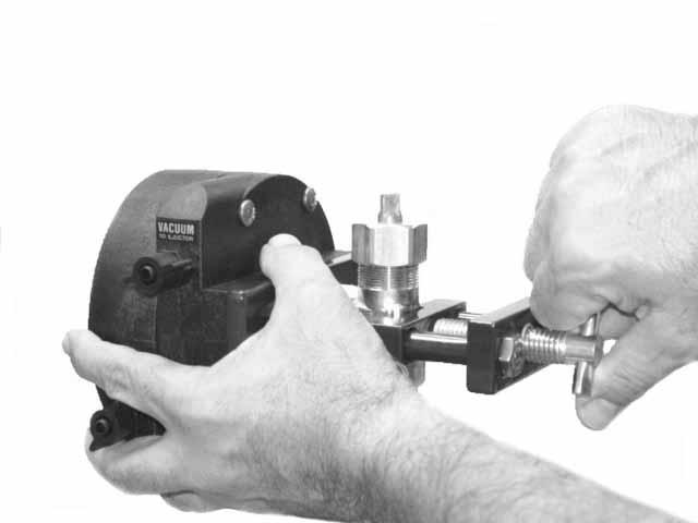
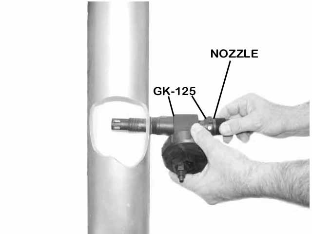
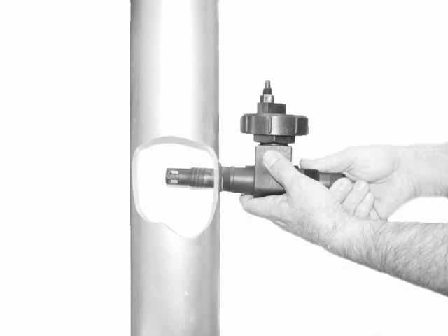
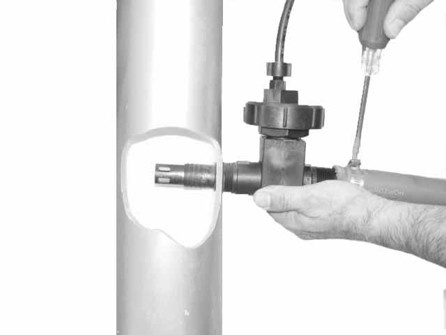
5 1.4.5 Ejector water supply pressure must be greater than the pressure into which solution is ejected. The amount of pressure differential may vary with the particular application. Generally, the greater the pressure into which the chlorine will be injected, the greater the required differential pressure. However, the minimum pressure differential and water flow for your installation should be determined prior to installation and start-up Follow these steps for installing close-coupled diffuser and ejector. a. Unscrew the diffuser from the assembly. DO NOT install the diffuser when the ejector is assembled or damage may occur. b. Put Teflon tape on the 1" pipe threads and screw the diffuser into the pipe. These are high-strength plastic parts, but like all plastic pipe fittings, care should be exercised in tightening. Tighten carefully with properly adjusted wrench. Make sure that the holes in the spray type diffuser are in the main stream. The end of an open type diffuser should not allow strong chlorine solution to come into contact with metal pipe or fittings, as this will cause serious cor- rosion. (Photo No. 1.2). c. Place a gasket (GK-125) into the recess on each side of the check valve body. Insert the nozzle through the check valve body (Photo No. 1.3). Hold the check valve body against the diffuser at ¼ turn COUNTER CLOCKWISE from its final position (up, down, side- ways). d. Screw the nozzle into the diffuser, by HAND ONLY, until contact is made against both gaskets. Turn the check valve body and the nozzle, at the same time, ¼ turn clockwise to the final, tight position (Photo No. 1.4). Attach water supply hose and tighten clamps. (Photo No. 1.5) Other types of diffuser and ejector installations may be desired for certain applications: 1.5 Piping of Ejector a. The ejector (nozzle and check valve assembly) may be located near the vacuum regulator. A wall mounting bracket can be provided for the assembly, and the outlet can be supplied with various sizes of adaptors for solution hose or pipe. b. If the ejector is to be remotely installed with solution piping or hose running to the point of application, be certain to cut off the tip of the diffuser before installing into the pipe or hose. Failure to do this will result in excessive back- pressure being created in the diffuser, causing chlorine feed rate to drop off or stop. c. The entire diffuser-ejector assembly may be submersed in an open channel or tank. d. Diffuser tubes with corporation cocks can be supplied for either close coupled or remote ejectors. e. Special diffusers can be supplied for use with PVC Ball valves For most installations, the ejector water supply line should be brought to within 3-5 feet of the nozzle with rigid copper or iron pipe, or schedule 80 PVC pipe A shut-off valve followed by a Y-type strainer and the ejector is desirable as a service tool, and is highly recommended A pressure gauge installed between the Y-type strainer and the ejector is desirable as a service tool, and is recommended very strongly Connect hose between the hose adaptor and the ejector nozzle. Clamp the hose securely at both ends with single or double hose clamps. (Photo No. 1.5) When rigid piping is used all the way up to the ejector inlet instead of hose, cut off the hose adaptor "barbs" on the nozzle where the 1" NPT threads start. Be certain to install pipe unions to allow maintenance. 1.6 Installation of Pressure Relief / Vent Valve Mount the pressure relief (vent) valve on the wall using the mounting bracket provided. Install with the "cross" fitting on top It is preferable to locate the pressure relief valve so it is approximately equidistant from the two vacuum regulators. However, this is not an absolute requirement Connect d" tubing to the bottom (vent) fitting and run the tubing outside the building to a safe location. Should the system become pressurized, the vent will expel excess chlorine gas into the atmosphere. An insect screen is provided for the outside of the vent line, and MUST be installed to prevent insects from entering the tubing and plugging the vent. 1.7 Connecting Vacuum Regulators to Pressure Relief Valve, Remote Meter, and to ejector Appropriate size plastic tubing is normally used for the vacuum line between the vacuum regulators and pressure relief/vent valve; pressure relief valve and remote meter; and the remote meter and ejector. Use enough length for each line to allow for movement of the vacuum regulators from one cylinder to another Remove connector nut from connector and slip onto tube. Push tube onto connector and tighten connector nut HAND TIGHT The connector on chlorinator vacuum regulator is for connecting the vacuum tubing to one of the side connectors on top of the pressure relief valve. The top connector on the pressure relief valve is connected to the lower connector on the remote meter panel. The upper connector on the remote meter is for connecting the vacuum tubing to the ejector. 1.8 Additional Installation Suggestions Many operators find it convenient to install a "hook" on the wall behind the chlorine cylinder, slightly above the vacuum regulator. When changing cylinders, the vacuum regulator can easily be hung on this "hook" while moving new cylinders into place A beam-type scale should be used to weigh chlorine cylinders while in use to determine the amount of chlorine remaining. 2.0 START-UP 2.1 Check Ejector The ejector, with its water supply and solution lines, must be properly installed and operating before checking the chlorinator: IMPORTANT: do not connect ejector to the chlorine vacuum tubing before applying water pressure to the ejector assembly. Dirt or debris can become lodged in the check valve during installation. Cycle the ejector on and off several times to insure tight closing. Failure to follow this procedure can cause water to enter the chlorinator, requiring disassembly Unless the ejector is creating a vacuum, the chlorinator 5
6 will not work. Follow these steps: a. Make sure the plastic vacuum tube is disconnected from the ejector. b. With the booster pump running, or pressurized water supply connected, open the ejector water supply valve. The ejector should be in operation and creating a vacuum. c. Put your finger on the vacuum connector opening of ejector and feel the vacuum. This is a strong vacuum and there should be no doubt that a vacuum exists. If there is no vacuum, refer to Section 1.4 and be certain the supply pressure is sufficient and that the nozzle or piping is not plugged. Correct the condition and obtain proper vacuum before proceeding. d. Be sure that no water is coming out of the vacuum tube fitting when the ejector is shut off. If water is observed leaking past the check valve, see Service Section 5.1 and correct before proceeding. e. Re-connect the vacuum tube to check chlorinator. Leave the ejector running. 2.2 Check Vacuum Regulators. Leave Chlorine Cylinder Valves Closed. (Have strong household ammonia and a piece of cloth available to check for chlorine leaks. Avoid breathing the fumes) Make sure that the knobs on both vacuum regulators are in the "ON" position by turning them counterclockwise until they "bottom out". DO NOT FORCE KNOBS With the cylinder valves closed, turn on water supply to the ejector Turn the rate valve in the remote flowmeter/rate valve panel counter-clockwise a few turns With the ejector operating, and the chlorine cylinders still closed, the ball in the metering tube will remain at the bottom. If the ball does not remain at the bottom, or bounces up and down, there is either a leak at the lead gasket where the vacuum regulator connects on the cylinder or a loose connection in the system. Check and correct Close the ejector water supply valve or turn off the booster pump to stop operation of the ejector Disconnect the plastic vacuum tube from one of the vacuum regulators and pull off the tube to allow air to enter system. Reconnect tubing Reset one of the vacuum regulators to STAND-BY by turning the "Reset" knob clockwise until the knob ratchets freely and does not unscrew any more. Then turn the knob counter-clockwise until it bottoms out. DO NOT FORCE THE KNOB. The lock nut on the end of the center pin should project completely past the end of the knob when the vacuum regulator is in "STAND-BY' mode. (See Drawing No. 2). IMPORTANT: Before proceeding, read "Precautions" Open chlorine cylinder valve 1/4 turn and close immediately Wet small piece of cloth in household ammonia (avoid breathing fumes) and hold below the lead gasket inlet connection and below the cylinder valve bonnet. If chlorine is leaking, a smoke will appear similar to cigarette smoke. Tighten bonnet or replace gasket and eliminate leaks. (NOTE: Do not pour ammonia solution on the vacuum regulator or cylinder valve) Open chlorine cylinder valve 1/4 turn, leave open, and recheck for chlorine leaks Repeat procedure for the second vacuum regulator. If no leaks are observed around the pressurized connections, check the vent outlet with ammonia fumes. If chlorine is detected at the vent, the inlet valve on one of the vacuum regulators is unable to close completely due to dirt or impurities from the chlorine, and must be cleaned before proceeding When you are certain that there are no chlorine leaks, turn on water supply valve to ejector and adjust rate valve to desired chlorine flow rate. Flow rate in lbs./24 hrs., or gr./hr. is read on the meter scale at the center of the ball for all flow rates except 200 to 500 PPD which are read at the top of the ball. NOTE: NEVER use the rate valve to shut off the chlorine supply. This valve is for adjusting flow rate while the system is in operation. To shut off chlorine flow close the cylinder valve Make certain that both chlorine cylinder valves are open ¼ turn, that one vacuum regulator is reset to "STAND-BY", and the reset knobs are turned fully counter-clockwise so that it is bottomed out against the face of the regulator. 3.0 SHUT-DOWN IMPORTANT: Before proceeding, read "Precautions". 3.1 Shut off water supply valve and/or booster pump. 3.2 Shut off the chlorine cylinder valve - not the rate valve. 3.3 When changing cylinders, follow the procedure on the cylinder changing chart supplied with your SUPERIOR Gas Chlorinator. Make certain that the cylinder valve is closed before removing the vacuum regulator. 4.0 RESETTING TO "STAND-BY" AFTER A CYLINDER HAS EMPTIED 4.1 Be certain the chlorine cylinder valve is turned off. If the valve will not turn clockwise, try to open the valve by turning counter-clockwise. If it will not turn in either direction, assume the valve is stuck in the open position and call your chlorine supplier. 4.2 Before removing the vacuum regulator from an empty cylinder, reset the regulator to "STAND-BY" by turning the Reset knob clockwise to engage the latching mechanism (See 2.2.5). 4.3 Turn the reset knob counter-clockwise until it bottoms against the regulator face. DO NOT FORCE KNOB. 4.4 Follow the procedure for changing cylinders on the "CHLORINATOR CYLINDER CHANGING PROCEDURE" supplied with the chlorinator. Chemical Injection Technologies, Inc. 835 Edwards Road, Ft. Pierce, FL, 34982, USA (772) Fax: (772) Superior@chlorinators.com
Instruction Manual - Diaframless TM Ejector Chlorine, Sulfur Dioxide and Ammonia
 Instruction Manual - Diaframless TM Ejector Chlorine, Sulfur Dioxide and Ammonia - 1-122.6010.6 These instructions describe the installation, operation and maintenance of the subject equipment. Failure
HGC-200 Hydro Gas Chlorinator
 HGC-200 Hydro Gas Chlorinator ProMinent Fluid Controls Pty Ltd Head Office: Unit 4, 4 Narabang Way BELROSE NSW 2085 AUSTRALIA (PO Box 85, BELROSE WEST NSW 2085) Phone: (02) 9450 0995 Fax: (02) 9450 0996
Instruction Manual O-Ring Ejector Chlorine & Sulfur Dioxide to 500 PPD (10 kg/h)
") Instruction Manual O-Ring Ejector Chlorine & Sulfur Dioxide to 500 PPD (10 kg/h) 100 PPD (2 kg/h) Maximum 250 PPD (5 kg/h) Maximum 500 PPD (10 kg/h) Maximum - 1-122.6006.9 These instructions describe the
Instruction Manual O-Ring Ejector Chlorine & Sulfur Dioxide to 500 PPD (10 kg/h) 100 PPD (2 kg/h) Maximum 250 PPD (5 kg/h) Maximum 500 PPD (10 kg/h) Maximum - 1-122.6006.9 These instructions describe the
Model VR6 System. Installation, Operation & Maintenance
 Model VR6 System Installation, Operation & Maintenance General: All Archer Instruments chlorination systems are carefully designed and tested for years of safe, accurate field service. All Archer Instruments
Gas Chlorination Systems Series E5000 Up to 100ppd Instruction Manual
 Gas Chlorination Systems Series E5000 Up to 100ppd Instruction Manual All ENCHLOR Chlorination systems are carefully designed and tested for years of safe, accurate field service. All ENCHLOR Chlorination
Instruction Manual ADVANCE Series 480 Vacuum Regulator
 Instruction Manual ADVANCE Series 480 Vacuum Regulator 80 60 40 20 R - 1-100.6001.15 These instructions describe the installation, operation and maintenance of the subject equipment. Failure to strictly
INTRODUCTION IMPORTANT NOTES AND WARNINGS
 INSTRUCTION BULLETIN 26 044 SE Dixie Cutoff Road, Stuart, Florida 34994 USA Phone: (772) 288-4854 Fax: (772) 287-3238 www.regalchlorinators.com Email: regal@regalchlorinators.com REGAL Gas Chlorinator,
Capital Controls Series NXT3000 Modular design gas feed system with self-contained automatic switchover capability.
 Capital Controls Series NXT3000 Modular design gas feed system with self-contained automatic switchover capability. The Series NXT3000 Gas Feed System is a family of vacuum-operated, solution-feed gas
Instruction Manual Series 200 ADVANCE Cylinder or Ton Container Mounted Vacuum Regulators
 Instruction Manual Series 200 ADVANCE Cylinder or Ton Container Mounted Vacuum Regulators 100 & 250 PPD (2 & 5 kg/h) Cylinder Mounted 500 PPD (10 kg/h) Cylinder Mounted 500 PPD (10 kg/h) Ton Container
INTRODUCTION IMPORTANT NOTES AND WARNINGS
 INSTRUCTION BULLETIN 2 044 SE Dixie Cutoff Road, Stuart, Florida 34994 USA Phone: (772) 288-4854 Fax: (772) 287-3238 www.regalchlorinators.com Email: regal@regalchlorinators.com REGAL Gas Chlorinator,
CAPITAL CONTROLS SERIES NXT3000
 CAPITAL CONTROLS SERIES NXT3000 Modular design gas feed system with self contained automatic switchover capability. The Series NXT3000 Gas Feed System is a family of vacuumoperated, solution-feed gas dispensing
Automatic Switchover Gas Chlorination Systems Series 900
 Automatic Switchover Gas Chlorination Systems Series 900 Instruction Manual All Hydro Instruments Chlorination systems are carefully designed and tested for years of safe, accurate field service. All Hydro
Chemical Feed Equipment Floor-Mounted Gas Dispenser - Series CH4200
 Specification Bulletin (rev.01) Series CH4200 Chemical Feed Equipment Floor-Mounted Gas Dispenser - Series CH4200 Easy, fast& accurate digital with 11 points calibration Laser sensor offering actual feed
Halsey Taylor Owners Manual STOP!
 Halsey Taylor Owners Manual 4710 Freeze Resistant Floor Mounted Steel Fountain STOP! PLEASE READ THE FOLLOWING INFORMATION. ITALLATION ITRUCTIO FOR THE 4710FR FTN. WITH 97243C SINGLE VALVE CONTROL ASSEMBLY
Installation Instructions for NP100 Series Nitrogen Control Panels
 Installation Instructions for NP100 Series Nitrogen Control Panels Installation of the Nitrogen Control Panel involves installing the rough-in box and making the necessary piping connections in accordance
Type S301 & S302 Gas Regulators INTRODUCTION INSTALLATION. Scope of Manual. Description. Specifications. Type S301 and S302. Instruction Manual
 Fisher Controls Instruction Manual Type S301 & S302 Gas Regulators October 1981 Form 5180 WARNING Fisher regulators must be installed, operated, and maintained in accordance with federal, state, and local
Assembly Drawing: W-311B-A01, or as applicable Parts List: W-311B-A01-1, or as applicable Special Tools: , , &
 REDQ Regulators Model 411B Barstock Design Powreactor Dome Regulator OPERATION AND MAINTENANCE Contents Scope..............................1 Installation..........................1 General Description....................1
ABRASIVE REGULATOR II
 ABRASIVE REGULATOR II 13096 Abrasive Regulator II TABLE OF CONTENTS Contact Information and Customer & Technical Service... 1 1 Introduction... 1 2 Abrasive Regulator... 1 Description:... 1 2.1 Regulator
Installation Operating Instructions for Simple Duplex Manual Manifolds PX-TSD Series
 Introduction Powerex manifolds are cleaned, tested and prepared for the indicated gas service and are built in accordance with the Compressed Gas Association guidelines. The manifold consists of a regulator
Halsey Taylor Owners Manual 4410 Freeze Resistant Tubular Fountain STOP!
 Halsey Taylor Owners Manual 4410 Freeze Resistant Tubular Fountain STOP! PLEASE READ THE FOLLOWING INFORMATION. ITALLATION ITRUCTIO FOR THE 4410FR FTN. WITH 97243C SINGLE VALVE CONTROL ASSEMBLY ARE LOCATED
MEGR-1627 Instruction Manual
 MEGR-1627 HIGH FLOW GAS REGULATOR Instruction Manual- Look Inside For: Description Installation Remote Vent Line Installations Startup and Adjustment Shutdown Maintenance Body Maintenance Procedures Diaphragm
Pressure Dump Valve Service Kit for Series 2300 Units
 Instruction Sheet Pressure Dump Valve Service Kit for Series 00 Units. Overview The Nordson pressure dump valve is used to relieve hydraulic pressure instantly in Series 00 applicator tanks when the unit
Operation & Maintenance Manual Place this manual with valve or person responsible for maintenance of the valve
 Operation & Maintenance Manual Place this manual with valve or person responsible for maintenance of the valve Model CYCLE GARD II, CI & CNA YOUR PRODUCT INFORMATION: Model Number: Date: Serial Number:
V43 Pressure Actuated Water Regulating Valve
 FANs 125, 121 Product/Technical Bulletin V43 Issue Date 0996 V43 Pressure Actuated Water Regulating Valve The V43 Pressure Actuated Water Regulating Valves are designed to regulate water flow for water-cooled
INSTALLATION INSTRUCTIONS. CVS 67CFR Pressure Reducing Instrument Supply Regulator INTRODUCTION
 INSTALLATION INSTRUCTIONS CVS 67CFR Pressure Reducing Instrument Supply Regulator INTRODUCTION The CVS Controls 67CFR Filter regulator is a pressure reducing supply regulator typically used for pneumatic
OPERATING AND MAINTENANCE MANUAL
 Series 4300 Engineered Performance TABLE OF CONTENTS 0 INTRODUCTION 1 1 Scope 1 2 Description 1 3 Specifications 1 0 INSTALLATION 1 1 Mounting 1 2 Piping 1 1 Connecting Process Pressure 2 2 Vent Connections
Chlorinator MODEL MK-I
 Chlorinator MODEL MK-I The New model MK- I is semi automatic gas type. Vacuum operated Solution feed Chlorinator designed to provide a continues & measured quantity of gas while in operation. It is suitable
Instruction Manual Updated 7/26/2011 Ver. 2.2
 4-Unit Model MB HTHP Filter Press #171-50-4: 115-Volt #171-51-4: 230-Volt Instruction Manual Updated 7/26/2011 Ver. 2.2 OFI Testing Equipment, Inc. 11302 Steeplecrest Dr. Houston, Texas 77065 U.S.A. Tele:
SUMMITTM 400 & 600. Natural Gas Barbecues. Step-By-Step Guide
 SUMMITTM 400 & 600 Natural Gas Barbecues Step-By-Step Guide W E B E R W E B E R W E B E R W E B E R Summit 400 NG Summit 600 NG CANADIAN GAS ASSOCIATION R A P P R O V E D WARNING: Follow all leak check
ABRASIVE REGULATOR II
 ABRASIVE REGULATOR II 13096 Abrasive Regulator II TABLE OF CONTENTS 1 Introduction... 1 2 Abrasive Regulator... 2 2.1 Regulator Installation... 2 Location... 2 Attaching the Regulator to the Machine...
! WARNING. Model PFC-1-G (direct acting) PFC-1-GR (reverse acting) Modulating Pneumatic Liquid Level Controls INSTRUCTION MANUAL MM-110B
 PFC-1-GR (reverse acting) Modulating Pneumatic Liquid Level Controls INSTRUCTION MANUAL MM-110B") INSTRUCTION MANUAL MM-110B Model PFC-1-G (direct acting) PFC-1-GR (reverse acting) Modulating Pneumatic Liquid Level Controls APPLICATIONS: Use with other pneumatic devices, for liquid level sensing in
INSTRUCTION MANUAL MM-110B Model PFC-1-G (direct acting) PFC-1-GR (reverse acting) Modulating Pneumatic Liquid Level Controls APPLICATIONS: Use with other pneumatic devices, for liquid level sensing in
Chlorinator. MODEL C-731 (Floor Mounted)
") Chlorinator MODEL C-731 (Floor Mounted) CHLOROTECH Model C-731 is the advance technology Chlorinator designed to feed chlorine gas at a controlled rate. The flow rate of gas is maintained by constant positive
Chlorinator MODEL C-731 (Floor Mounted) CHLOROTECH Model C-731 is the advance technology Chlorinator designed to feed chlorine gas at a controlled rate. The flow rate of gas is maintained by constant positive
Inert Air (N2) Systems Manual
 Systems Manual") INSTRUCTION MANUAL Inert Air (N2) Systems Manual N2-MANUAL 2.10 READ AND UNDERSTAND THIS MANUAL PRIOR TO OPERATING OR SERVICING THIS PRODUCT. GENERAL INFORMATION Positive pressure nitrogen gas pressurizing
INSTRUCTION MANUAL Inert Air (N2) Systems Manual N2-MANUAL 2.10 READ AND UNDERSTAND THIS MANUAL PRIOR TO OPERATING OR SERVICING THIS PRODUCT. GENERAL INFORMATION Positive pressure nitrogen gas pressurizing
TECHNICAL DATA. Pressure Regulation 531a. April 24, 2009
 April 24, 29 Pressure Regulation 531a 1. DESCRIPTION The Viking Regulating Valve is a direct-acting, single-seated, spring-loaded diaphragm valve. When installed as a pilot regulating valve on a Viking
2008 by Controlmatik ABW
 I N S T R U C T I O N M A N U A L F OR Installation and use of high capacity Vacuum regulator 2008 by Controlmatik ABW CONTENTS 1 GENERAL... 2 2 THE CHLORINE GAS DOSING SYSTEM... 2 2.1 Parts of the chlorine
Instruction Manual Pressure Relief Valve and Rupture Disc Chlorine or Sulfur Dioxide, Series 869
 Instruction Manual Pressure Relief Valve and Rupture Disc Chlorine or Sulfur Dioxide, Series 869-1 - 115.6020.15 These instructions describe the installation, operation and maintenance of the subject equipment.
TECHNICAL DATA. Page 1 of 12
 Page 1 of 12 1. DESCRIPTION The Viking Regulating Valve is a direct-acting, single-seated, spring-loaded diaphragm valve. When installed as a pilot regulating valve on a Viking Model H or J Flow Control
ABRASIVE SYSTEM ABRASIVE REGULATOR II 800# BULK ABRASIVE DELIVERY POT Abrasive Regulator II and 800# Pot Manual
 ABRASIVE SYSTEM ABRASIVE REGULATOR II 800# BULK ABRASIVE DELIVERY POT TABLE OF CONTENTS Contact Information and Customer & Technical Service... 1 1 Introduction... 1 2 Abrasive Regulator... 1 Description:...
1 DRIVE INDUSTRIAL IMPACT WRENCH
 1 DRIVE INDUSTRIAL IMPACT WRENCH 92622 ASSEMBLY AND OPERATING INSTRUCTIONS 3491 Mission Oaks Blvd., Camarillo, CA 93011 Visit our Web site at http://www.harborfreight.com Copyright 2004 by Harbor Freight
SERVICE MANUAL MODEL BA050BMST BREATHING AIR PANEL
 www.modsafe.com SERVICE MANUAL MODEL BA050BMST BREATHING AIR PANEL WARNING: Do not attempt to operate this equipment without first reading and understanding the service manual enclosed with this device.
Model: 720-UL INSTALLATION OPERATION MAINTENANCE. Bermad Pressure Reducing Valve IOM. Model: FP -720-UL Sizes: 2"-12" BERMAD. Application Engineering
 Bermad Pressure Reducing Valve Model: 720-UL INSTALLATION OPERATION MAINTENANCE Application Engineering BERMAD 1. Safety First BERMAD believes that the safety of personnel working with and around our equipment
LARGE DRY CHEMICAL, TWIN-AGENT, AFFF, HALON 1211, AND AQUASONIC (NITROGEN-OPERATED SYSTEMS) Pressure Regulator Test Manual
 Pressure Regulator Test Manual") LARGE DRY CHEMICAL, TWIN-AGENT, AFFF, HALON 1211, AND AQUASONIC (NITROGEN-OPERATED SYSTEMS) Pressure Regulator Test Manual 002694 IntroductIon 8-1-11 Page 1 ForEWord This manual is intended for use with
LARGE DRY CHEMICAL, TWIN-AGENT, AFFF, HALON 1211, AND AQUASONIC (NITROGEN-OPERATED SYSTEMS) Pressure Regulator Test Manual 002694 IntroductIon 8-1-11 Page 1 ForEWord This manual is intended for use with
PRS(TC)4,8 USER MANUAL. Read the complete manual before installing and using the regulator.
4,8 USER MANUAL. Read the complete manual before installing and using the regulator.") PRS(TC)4,8 USER MANUAL Read the complete manual before installing and using the regulator. WARNING INCORRECT OR IMPROPER USE OF THIS PRODUCT CAN CAUSE SERIOUS PERSONAL INJURY AND PROPERTY DAMAGE. Due to
PRS(TC)4,8 USER MANUAL Read the complete manual before installing and using the regulator. WARNING INCORRECT OR IMPROPER USE OF THIS PRODUCT CAN CAUSE SERIOUS PERSONAL INJURY AND PROPERTY DAMAGE. Due to
2.5 & 5.0 GALLON PRESSURE TANKS
 2.5 & 5.0 GALLON PRESSURE TANKS Includes: MODEL 7025 MODEL 7026 MODEL 7027 MODEL 7028 2.5 Gallon Single Regulation (NON A.S.M.E.) 2.5 Gallon Dual Regulation (NON A.S.M.E.) 5.0 Gallon Single Regulation
Installation of Your SprayMaster System
 Installation of Your SprayMaster System 1. At the installation site, remove all equipment from the corrugated box and the polyethylene drum and replace the drum lid. Check the picture to identify each
LRS(H)4 USER MANUAL. Read the complete manual before installing and using the regulator.
4 USER MANUAL. Read the complete manual before installing and using the regulator.") LRS(H)4 USER MANUAL Read the complete manual before installing and using the regulator. WARNING INCORRECT OR IMPROPER USE OF THIS PRODUCT CAN CAUSE SERIOUS PERSONAL INJURY AND PROPERTY DAMAGE. Due to the
LRS(H)4 USER MANUAL Read the complete manual before installing and using the regulator. WARNING INCORRECT OR IMPROPER USE OF THIS PRODUCT CAN CAUSE SERIOUS PERSONAL INJURY AND PROPERTY DAMAGE. Due to the
Types 749B and R130 Changeover Manifolds
 Instruction Manual MCK-1179 Types 749B and R130 June 2012 Types 749B and R130 Changeover Manifolds TYPE HSRL-749B TYPE 64SR/122 TYPE R130/21 TYPE 749B/21 Figure 1. Changeover Manifolds and Regulator Assemblies
ATD LB PRESSURE BLASTER INSTRUCTION MANUAL
 ATD-8402 90LB PRESSURE BLASTER INSTRUCTION MANUAL SAVE THESE INSTRUCTIONS SAFETY INSTRUCTIONS FOR SANDBLASTER 1. Before opening the tank release the air pressure on the sand tank. To do this, turn off
MODEL 1329 Tank Gauge
 SERVICE INSTRUCTIONS FOR PETRO-METER 1329 GAUGE SERVICE INSTRUCTIONS MODEL 1329 Tank Gauge www.petro-meter.com Petro-Meter 1329 series Service Instructions HOW TO DETERMINE IF A PETRO-METER IS IN GOOD
AIR-OPERATED DOUBLE DIAPHRAGM PUMP USER S MANUAL
 00, 0, 000 00, 000, 00 A. TECHNICAL INFORMATION Model 00 Inlet/Outlet " Air Inlet /" 0 / 000 /" /" 00 /" /" 000 /" /" 00 /" /" Flow Rate GPM/ 0LPM GPM/ 0LPM GPM/ LPM GPM/ LPM GPM/ 0LPM GPM/ 0LPM Maximum
Pressure Differential Automatic Manifold For LPG. PDH1000 Series. LPG Installation & Operations Instructions
 Pressure Differential Automatic Manifold For LPG PDH1000 Series LPG Installation & Operations Instructions Precise Equipment Company 3822 Market St., STE 101 Denton, Texas Phone : 800.795.8388 Precise
INSTALLATION & MAINTENANCE INSTRUCTION
 ARCHON Industries, Inc Liquid Level Gauges Models: BT-LLG ND-LLG INSTALLATION & MAINTENANCE INSTRUCTION Instruction No.: 1014.2 Revision Issued: 3/01/03 Approved: Engineering Manager Warning ONLY QUALIFIED
DS05C,D,G Dial Set Pressure Regulating Valves
 DS05C,D,G Dial Set Pressure Regulating Valves APPLICATION The Honeywell DS05C,D,G Dial Set Pressure Regulating Valve is a high quality pressure regulating valve that maintains a constant outlet pressure
Instructions. Control Solution ICF 20-4, ICF 25-4, ICF ICF 40-4, ICF 20-6, ICF 25-6, ICF 32-6, ICF 40-6, Direction and position.
 027R9782 Instructions Control Solution ICF 20-4, ICF 25-4, ICF 32-4. ICF 40-4, ICF 20-6, ICF 25-6, ICF 32-6, ICF 40-6, Direction and position ICF xx-4 ICF xx-6 ICF xx-4 / ICF xx-6 with ICM ICM 027R9782
Welker Sampler. Model GSS-1. Installation, Operation, and Maintenance Manual
 Installation, Operation, and Maintenance Manual Welker Sampler Model GSS-1 The information in this manual has been carefully checked for accuracy and is intended to be used as a guide to operations. Correct
INSTRUCTIONS FOR MODELS SG3897 AND SG3898 CROSS PURGE ASSEMBLIES
 INSTRUCTIONS FOR MODELS SG3897 AND SG3898 CROSS PURGE ASSEMBLIES THIS BOOKLET CONTAINS PROPRIETARY INFORMATION OF ADVANCED SPECIALTY GAS EQUIPMENT CORP. AND IS PROVIDED TO THE PURCHASER SOLELY FOR USE
1200B2 Series Service Regulators. Instruction Manual
 00B Series Service Regulators Instruction Manual 00B Series Service Regulators 0 Elster American Meter 00B Series Service Regulators General Information The 00B Series Service Regulators are available
2.0 INSTALLATION & SERVICE
 Installation, Operation, and Maintenance Instructions MODEL 5600 / 5600R January 2005 CONTENTS 1.0 GENERAL 1.1 5600 Model Number Information -----------------------------------------------------------------------
SERVICE MANUAL MODEL BA100BMST 100 SCFM PORTABLE AIR PANEL
 Product Manual MST Portable Air Filtration System SERVICE MANUAL MODEL BA100BMST 100 SCFM PORTABLE AIR PANEL WARNING: Do not attempt to operate this equipment without first reading and understanding the
User's Manual. MixRite TF 10. Edition 05.08
 User's Manual MixRite TF 10 Edition 05.08 1 Tefen MixRite TF 10 fertilizer and chemicals Injector Congratulations on your purchase of one of Tefen s high quality products. To get the best results from
Vacuum Operated Liquid Chemical Feed Systems
 Vacuum Operated Liquid Chemical Feed Systems Instruction Manual All HYDRO Chemical Feed systems are carefully designed and tested for years of safe, accurate field service. All HYDRO systems are tested
PRESSURISED PAINT CONTAINER
 PRESSURISED PAINT CONTAINER MODEL NO: CPP2B PART NO: 3082115 OPERATION & MAINTENANCE INSTRUCTIONS GC0913 INTRODUCTION Thank you for purchasing this CLARKE Pressurised Paint Container. Before attempting
Service and Repair Manual
 II stage R2 Ice/ Special, II stage R 1 Pro DOWNSTREAM 2 nd STAGE REGULATOR Service and Repair Manual Introduction Safety Precautions...4 General Procedures, Maintenance Schedules...5 Initial Inspection
TECHNICAL DATA CAUTION
 Page 1 of 12 1. DESCRIPTION The Viking Model C-2 Pilot Pressure Regulating Valve is a direct-acting, single-seated, spring-loaded diaphragm valve. When installed as a pilot regulating valve on a Viking
OPERATION MANUAL NTF-15
 OPERATION MANUAL NTF-15 Nitrogen Tire Filling Valve Stem Caps (Qty=200) Order P/N 436075 RTI Technologies, Inc 10 Innovation Drive York, PA 17402 800-468-2321 www.rtitech.com 035-81235-00 (Rev B) TABLE
NB/NBR NITROGEN BOOSTER FOR AVIATION SERVICE
 NB/NBR NITROGEN BOOSTER FOR AVIATION SERVICE INSTALLATION, OPERATION & MAINTENANCE MANUAL INTERFACE DEVICES, INC. 230 Depot Road, Milford, CT 06460 Ph: (203) 878-4648, Fx: (203) 882-0885, E-mail: info@interfacedevices.com
Natural Gas Conversion Kit
 SERIAL #: Attention: Centro recommends that a qualified gas technician perform the gas supply conversion and orifice replacement for this BBQ model. Natural Gas Conversion Kit F O R U S E W I T H M O D
MMR Air Mask With. with Quick-Connect Hose
 MMR Air Mask With with Quick-Connect Hose Upgrade Kits P/N 10025120 Slide to Connect P/N 10050038 Slide to Connect w/ Solid Cover P/N 10038666 Push To Connect P/N 10050037 Push To Connect w/ Solid Cover
OPERATION MANUAL NTF-60 Plus
 OPERATION MANUAL NTF-60 Plus Nitrogen Tire Filling Valve Stem Caps (Qty=200) Order P/N 436075 RTI Technologies, Inc 10 Innovation Drive York, PA 17402 800-468-2321 www.rtitech.com 035-81264-00 (Rev A)
Speed control assembly model A-1
 Pressure Regulation 533a 1. DESCRIPTION The Viking Speed Control Assembly provides adjustment of the opening speed of Viking Deluge Valves, and adjustment of both the opening and closing speed of Viking
Highest Quality. Gas Chlorination Systems
 Highest Quality Gas Chlorination Systems Application: Gas chlorination systems are used for water disinfection and other purposes in a variety of applications. Compared to other disinfection methods, chlorine
Gas Lines. Technical Manual. Sumitomo (SHI) Cryogenics of America, Inc Vultee Street Allentown, PA U.S.A.
 Cryogenics of America, Inc Vultee Street Allentown, PA U.S.A.") Gas Lines Technical Manual Sumitomo (SHI) Cryogenics of America, Inc. 1833 Vultee Street Allentown, PA 18103-4783 U.S.A. Revision F: April 2008 261320A TABLE OF CONTENTS Page DESCRIPTION...1 SPECIFICATIONS...2
Gas Lines Technical Manual Sumitomo (SHI) Cryogenics of America, Inc. 1833 Vultee Street Allentown, PA 18103-4783 U.S.A. Revision F: April 2008 261320A TABLE OF CONTENTS Page DESCRIPTION...1 SPECIFICATIONS...2
DBML-60/80 Squeeze Tool
 DBML-60/80 Squeeze Tool OPERATORS MANUAL Description The Mustang Model DBML-60/80 Hydraulic squeeze tool has been manufactured since 1995. A Mustang 3 3/4 bore doubleacting cylinder producing 41,000 lbs
RHPS Series RD(H)F40 User Manual. Read the complete manual before installing and using the regulator.
F40 User Manual. Read the complete manual before installing and using the regulator.") RHPS Series RD(H)F40 User Manual Read the complete manual before installing and using the regulator. 2 WARNING Before removing a regulator from the system for service, you must depressurize system purge
RHPS Series RD(H)F40 User Manual Read the complete manual before installing and using the regulator. 2 WARNING Before removing a regulator from the system for service, you must depressurize system purge
Operation Manual. Diaphragm Sensed Gas Pressure Regulators
 687 Technology Way Napa, CA 94558 Phone: (707) 259-0102 FAX: (707) 259-0117 www.aptech-online.com Diaphragm Sensed Gas (AP/AZ/AK Models: 20, 100, 500, 1000, 1000T 10PA, 1100, 1200, 12PA, 1300, 1400T, 14PA,
ACV-10 Automatic Control Valve
 ACV-10 Automatic Control Valve Installation, Operation & Maintenance General: The Archer Instruments ACV-10 is a precision automatic feed rate control valve for use in vacuum systems feeding Chlorine,
3/8" Dr. Air Butterfly Impact Wrench
 8192106 3/8" Dr. Air Butterfly Impact Wrench Owner s Manual Read and understand all instructions before use. Retain this manual for future reference. Specifications Construction: Polished aluminum and
Booster Pump PB4-60 Replacement Kits
 Booster Pump PB4-60 Replacement Kits FOR YOUR SAFETY - This product must be installed and serviced by a contractor who is licensed and qualified in pool equipment by the jurisdiction in which the product
D05 Pressure Regulating Valves
 D05 Pressure Regulating Valves FEATURES PRODUCT DATA Noncorroding unitized cartridge contains all working parts and is easily replaceable. Includes built-in strainer and thermal bypass. Balanced seat construction
Pressure Dump Valve Service Kit for Series 3000 Units
 Instruction Sheet Pressure Dump Valve Service Kit for Series 000 Units. Overview The Nordson pressure dump valve is used to relieve hydraulic pressure instantly in Series 00, 400, 500, and 700 applicator
Model 420-HY Pressure Regulating Hydrant Valve
 Model 420-HY Pressure Regulating Hydrant Valve INSTALLATION OPERATION MAINTENANCE 1. Safety First BERMAD believes that the safety of personnel working with and around our equipment is the most important
256 Pneumatic Pressure Indicator
 256 Pneumatic Pressure Indicator 51425699 Copyright 2002 Slope Indicator Company. All Rights Reserved. This equipment should be installed, maintained, and operated by technically qualified personnel. Any
MUELLER GAS. No-Blo Operations Using D-5. Drilling Machine. Reliable Connections. General Information 2
 operating Instructions manual MUELLER GAS TAble of contents PAGE No-Blo Operations Using D-5 General Information 2 Installing No-Blo Service Tees, Service Stop Tees and Curb Stop Tees 3-8 Reconditioning
CRYOGENIC TANK SERVICES - CHART RECORDER MANUAL
 CRYOGENIC TANK SERVICES - CHART RECORDER MANUAL Pressure Chart Recorder / Temperature Chart Recorder / Dual Recorder Portable Mechanical Chart Recorder for the accurate measurement and recording of Pressure
MANUAL BE SERIES Test Benches
 The CustomCrimp Manual BE Series Test Benches are designed with features that make proof and burst testing of hydraulic hose assemblies a quick and easy procedure. CUSTOMIZED AND SPECIAL DESIGN BENCHES
Operation Manual Piston Sensed Gas Pressure Regulators
 687 Technology Way Napa, CA 94558 Phone: (707) 259-0102 FAX: (707) 259-0117 www.aptech-online.com Operation Manual Piston Sensed Gas Pressure Regulators (Models KT9, KT10, Welded KT10, KT12) Table of Contents:
Installation Operating Instructions for Duplex Manual Manifolds PX-TMD Series
 Introduction Powerex manifolds are cleaned, tested and prepared for the indicated gas service and are built in accordance with the Compressed Gas Association guidelines. The manifold consists of a regulator
3 GALLON, OILLESS PANCAKE COMPRESSOR INSTRUCTIONS. Item #31289
 3 GALLON, OILLESS PANCAKE COMPRESSOR INSTRUCTIONS Item #31289 The EASTWOOD 3 GALLON, OILLESS PANCAKE COMPRESSOR, with an Integral Air Regulator, efficiently supplies all compressed air requirements for
299H Series. Introduction. P.E.D. Categories. Specifications. Installation. Warning. Installation Guide English September 2012
 Installation Guide English September 2012 299H Series Introduction This Installation Guide provides instructions for installation, startup, and adjustment of 299H Series regulators. To receive a copy of
Type OS2 Slam-Shut Device
 Instruction Manual D102778X012 Type OS2 April 2018 Type OS2 Slam-Shut Device! Warning Failure to follow these instructions or to properly install and maintain this equipment could result in an explosion
Valve Station ICF 15, 20 and 25
 Installation Guide Valve Station ICF 15, 20 and 25 027R9782 Installation ICF xx-4 ICF xx-6 ICF xx-4 / ICF xx-6 + 027R9782 1a 1b 1c Welding TIG/MIG/SMAW Gas welding Danfoss M27L0049_1 2 3 Danfoss A/S (RC-MDP/MWA),
INSTALLATION INSTRUCTIONS MANUAL ON/OFF SAFETY VALVE/PILOT KIT MODEL GA9050A-1 (F0235)
") P/N 126905-01 Rev. B 11/2016 INSTALLATION INSTRUCTIONS MANUAL ON/OFF SAFETY VALVE/PILOT KIT MODEL GA9050A-1 (F0235) For All Single, Dual and Triple Burner Natural and Propane/LP Gas Logs P126905-01 For
P/N 126905-01 Rev. B 11/2016 INSTALLATION INSTRUCTIONS MANUAL ON/OFF SAFETY VALVE/PILOT KIT MODEL GA9050A-1 (F0235) For All Single, Dual and Triple Burner Natural and Propane/LP Gas Logs P126905-01 For
RS(H)10,15 USER MANUAL. Read the complete manual before installing and using the regulator.
10,15 USER MANUAL. Read the complete manual before installing and using the regulator.") RS(H)10,15 USER MANUAL Read the complete manual before installing and using the regulator. WARNING INCORRECT OR IMPROPER USE OF THIS PRODUCT CAN CAUSE SERIOUS PERSONAL INJURY AND PROPERTY DAMAGE. Due to
RS(H)10,15 USER MANUAL Read the complete manual before installing and using the regulator. WARNING INCORRECT OR IMPROPER USE OF THIS PRODUCT CAN CAUSE SERIOUS PERSONAL INJURY AND PROPERTY DAMAGE. Due to
Model: 43T. Bermad Pressure Relief Valve
 Model: 43T Bermad Pressure Relief Valve Installation Operation Maintenance Manual () Rev.C1_01.08.17 Page 1 of 10 Safety First BERMAD believes that the safety of personnel working with and around our equipment
JARVIS. Model CPE Hock and Neck Cutter EQUIPMENT... TABLE OF
 74 Hock and Neck Cutter EQUIPMENT SELECTION... Ordering No. TABLE OF CONTENTS... Page with Control Circuit. 4304003 only... 4304004 Balancer... 1350084 Control Circuit... 3350010 Air Hose (Yellow)... 3323003
Steel Spring Driven Reel Instruction Manual
 Steel Spring Driven Reel Instruction Manual WARNING: Read carefully and understand all INSTRUCTIONS before operating. Failure to follow the safety rules and other basic safety precautions may result in
Operating Procedures for GripTight 15.5 SDR & IPS Test Plugs
 EST Group DC2518 08/01 REV 3 12/12 Page 1 of 6 Operating Procedures for GripTight SDR & IPS Test Plugs WARNING For proper operation, GripTight plugs must be assembled as shown in Figure 1. Pressure testing
!!!! SERVICE MANUAL PRESSURE POT 2 GALLON. Service Manual: LT Washington St 931 Progress Ave., #7
 EXEL North America, Inc. EXEL Industrial Canada, Inc. 1310 Washington St 931 Progress Ave., #7 West Chicago, IL 60185 Scarborough ONT, M1G 3V5 Ph : (800) 573 5554 Ph : (800) 450 0655 Fx : (800) 664 1511
BULLETIN 901 SAFE RELIABLE ECONOMICAL REGAL GAS CHLORINATORS SULPHONATORS AMMONIATORS
 SAFE RELIABLE ECONOMICAL BULLETIN 901 GAS CHLORINATORS SULPHONATORS AMMONIATORS SAFE Safety starts right at the cylinder valve, with the heavy-duty vise-type mounting yoke. Safety is designed and built
5 Gallon Pressure Pot with HVLP Spray Gun and Hose
 California Air Tools 5 Gallon Pressure Pot with HVLP Spray Gun and Hose Model No. 365 Technical Data Type of feed.pressure Maximum pressure in the tank... 0,413Mpa (60PSI) Working pressure in the tank.0,