FCU 8000 series FluidControl Unit
|
|
|
- Ralph Griffin Miles
- 6 years ago
- Views:
Transcription
 Document no.")
1 FluidControl Unit Operating and Maintenance Instructions Valid from firmware versions 3.22 up English (translation of original instructions) Document no.: d
2 Trademarks Trademarks The trademarks of other companies designate the products of those companies exclusively. Copyright 2011 by HYDAC FILTER SYSTEMS GMBH all rights reserved All rights reserved. This manual may not be reproduced in part or whole without the express written consent of HYDAC Filter Systems GmbH. Contraventions are liable to compensation. Exclusion of liability We have made every endeavor to ensure the accuracy of the contents of this document. However, errors cannot be ruled out. Consequently, we accept no liability for such errors as may exist nor for any damage or loss whatsoever which may arise as a result of such errors. The content of the manual is checked regularly. Any corrections required will be incorporated in future editions. We welcome any suggestions for improvements. All details are subject to technical modifications. Technical specifications are subject to change without notice. HYDAC FILTER SYSTEMS GMBH Postfach Sulzbach / Saar Germany Documentation Representative Mr. Günter Harge c/o HYDAC International GMBH, Industriegebiet, Sulzbach / Saar Telephone: ++49 (0) Fax: ++49 (0) guenter.harge@hydac.com HYDAC FILTER SYSTEMS GMBH en(us) Page 2/112
3 Content Content Trademarks...2 Documentation Representative...2 Content...3 Preface...7 Customer service...8 Modifications to the Product...8 Warranty...8 Using the Documentation...9 Safety information and instructions...10 Obligations and liability...10 Explanation of symbols and warnings...11 Proper/Designated Use...11 Improper Use...12 What to Do in Case of Emergency...12 Maintenance, Servicing and Troubleshooting...12 Modifications to the FCU...12 Training of personnel...13 Checking the Scope of Delivery...14 Description of the FCU...15 Operating elements / Dimensions...16 Restrictions on use FCU 8110 / Restrictions on use FCU 8111 / Hydraulic diagram...18 FCU Function Description...19 Electrical connection of the FCU...22 Connecting the "POWER INPUT"...22 Connecting the "PC" interface...23 Serial RS 232 Interface (Standard)...23 Serial RS 485 Interface (OPTIONAL)...23 "Control" Connecting the control port...24 Contact assignment (switched position when the FCU is ready for operation)...24 Relay Functions...25 Adjustable limit values...28 FCU in online operation...29 FCU in BSU operation (only for FCU 8110 / 8210)...31 HYDAC FILTER SYSTEMS GMBH en(us) Page 3/112
4 Content Diagram of the BottleSampling Unit...33 Perform basic settings for bottle sampling operation...34 Flushing BottleSampling Unit...35 Measurement with BottleSampling Unit...36 Switching on the FCU...39 Switching on the FCU...39 Selecting the Viscosity Range...39 Starting up the FCU...40 Conducting Measurements via the High-Pressure Port (INLET)...40 Operating the FCU...40 Function of the Keys...40 Menu and Number Keys (red)...41 Key Combinations...41 FCU menus...42 MODE - select operating mode...42 MODE "M1: Measure"...43 MODE "M2: Measuring and switching"...43 MODE "M3: Filter to" (performance of automatic filtration)...43 MODE "M4: Filtering from to" (performance of automatic filtration)...44 MODE "M5: Flushing BS"...44 MODE "M6: Bottle Sampler"...44 MEMORY Menu...45 Designating the measurement point...46 Setting the averaging interval...47 Selective deletion...48 Delete all...50 Change meas. point...51 Setting the memory mode...52 Overwrite...52 Stop if full...52 PRINT menu...53 Logs...54 BS-Logs...59 PRINT Contents...63 PRINT All parameters...63 Paper feed...64 Online printout...64 Print out, cancel...65 LIMITS menu...65 MODE M HYDAC FILTER SYSTEMS GMBH en(us) Page 4/112
5 Content Measurement channel table...68 MODE M MODE M MODE M MODE M SETUP menu...72 Auto...73 Abort at Q= Setting the pump delay...75 Setting the date and time...76 Set bus address...77 Display operating hours...77 BS pressure supply...78 Additional test...78 Check the battery status...79 POWERUP menu...80 M6: Bottle Sampler...81 Selecting the language...82 Setting the viscosity range...82 Setting the measured volume...83 FCU Display...84 Brief Overview of the Menu Structure...86 Error Messages and Troubleshooting...89 Performing maintenance...94 Cleaning the FCU...94 Changing the FCU Filter Element...94 Back-flushing the FCU...97 Internal dot-matrix impact printer replace paper roll / ink ribbon...97 Disposing of the FCU...99 Storing the FCU...99 Storage conditions...99 Calibrating the FCU...99 Customer service Germany USA Australia Brazil China Spare parts HYDAC FILTER SYSTEMS GMBH en(us) Page 5/112
6 Content FCU 8xx0 (version for mineral oil) FCU 8xx1 (version for HFD fluids) FCU 8xxx Accessories Explanation of the measuring technology terms used Overview - ISO 4406 / SAE AS 4059 and NAS 1638 classes ISO 4406: ISO 4406 table Overview of the differences between ISO 4406:1987 and ISO 4406: SAE AS SAE AS 4059 table Cleanliness codes according to SAE Absolute particle count larger than a defined particle size Specifying a cleanliness code for each particle size Specifying the highest cleanliness code measured NAS Technical data Factory default settings HYDAC FILTER SYSTEMS GMBH en(us) Page 6/112
7 Preface Preface For you as the owner of a product manufactured by us, we have produced this manual, comprising the most important instructions for its operation and maintenance. It will acquaint you with the product and assist you in obtaining maximum benefit in the applications for which it is designed. Keep the manual in the vicinity of the device for immediate reference. Sometimes the information contained in the documentation cannot always keep up with changes made to the product as we attach considerable importance to keeping our products cutting-edge. Consequently, there might be deviations in technical details, illustrations and dimensions. If you discover errors while reading the documentation or have additional suggestions or notes, contact us at: HYDAC FILTER SYSTEMS GMBH Technische Dumentation Postfach Sulzbach / Saar Germany The editorial department los forward to receiving your input. Our motto: Putting experience into practice HYDAC FILTER SYSTEMS GMBH en(us) Page 7/112
8 Preface Customer service Contact our technical sales department if you have any questions on our product. When contacting us, please always include the model/type designation and article no. of the product: Fax: +49 (0) 6897 / filtersystems@hydac.com Modifications to the Product We would like to point out that changes to the product (e.g. purchasing options, etc.) may result in the information in the operating instructions no longer being completely accurate or sufficient. When making modifications or performing repair work to components affecting the safety of the product, the product may not be put back into operation until it has been examined and released by a HYDAC representative. Please notify us immediately of any modifications made to the product whether by you or a third party. Warranty For the warranty provided by us, please refer to the General Terms of Sale and Delivery of HYDAC FILTER SYSTEMS GmbH. They are available at: -> Legal information. HYDAC FILTER SYSTEMS GMBH en(us) Page 8/112
9 Preface Using the Documentation Please note that the method described above of locating specific information does not release you from your responsibility for carefully reading the entire manual prior to ing the unit up for the first time and carefully rereading the manual at regular intervals later on. WHAT do I want to know? I determine the topic I am loing for. WHERE can I find the information I m loing for? The documentation has a table of contents at the beginning. There, I select the chapter I'm loing for and the corresponding page number. Chapter Produkt / Kapitel Page number HYDAC Filtertechnik GmbH BeWa a de de Seite x 200x-xx-xx Edition date Documentation No. with Index / File name Document language The documentation number with its index enables you to order another copy of the operating and maintenance instructions. The index is incremented by one every time the manual is revised or changed. HYDAC FILTER SYSTEMS GMBH en(us) Page 9/112
10 Safety information and instructions Safety information and instructions These operating instructions contain the key instructions for properly and safely operating the FCU. Obligations and liability The basic prerequisite for the safe and proper handling and operation of the FCU is knowledge of the basic safety instructions and regulations. These operating instructions in general, and the safety precautions in particular, are to be adhered by all those who work with the FCU. In addition, the accident prevention rules and regulation applicable at the location of use are to be observed. The FCU has been designed and constructed in accordance with the current state of the art and recognized safety regulations. Nevertheless, hazards may be posed to the life and limb of the individual using the product or to third parties. Risk of damage may be posed to the product or other equipment and property. Use the FCU: Solely for its designated use Only when in safe, perfect condition. Immediately remedy any malfunctions that might impair safety. Always keep the operating and maintenance instructions near the measurement device. In addition to the operating instructions, the general and local regulations on accident prevention and environmental protection are to be made available and observed. Ensure that all information relating to safety and potential hazards of the FCU are kept in a legible condition.replace them if necessary. Replace them if necessary. Check the hoses and connectors for leaks on a daily basis. WARNING Hydraulic systems are under pressure Danger of bodily injury Depressurize the system before performing any work on it. HYDAC FILTER SYSTEMS GMBH en(us) Page 10/112
11 Safety information and instructions Explanation of symbols and warnings The following designations and symbols are used in this manual to designate hazards, etc.: DANGER WARNING DANGER NOTICE DANGER denotes situations which can lead to death if safety precautions are not observed. WARNING denotes situations which can lead to death if safety precautions are not observed. DANGER denotes situations which can lead to severe injuries if safety precautions are not observed. NOTICE denotes situations which can lead to property damage if safety precautions are not observed. Proper/Designated Use The Contamination Sensor (FCU) was developed for temporary or continuous monitoring of particulate contamination in hydraulic systems. Analyzing the type, size and quantity of contamination enables quality standards to be verified and documented, and the requisite optimization measures to be implemented. Any other use shall be deemed to be improper and not in keeping with the product's designated use; the manufacturer accepts no liability for any damage resulting from such use. Proper or designated use of the product extends to the following: Maintaining adherence to all the instructions contained herein. Performing requisite inspection and maintenance work. HYDAC FILTER SYSTEMS GMBH en(us) Page 11/112
12 Safety information and instructions Improper Use Any use other than described above is prohibited. Improper use may result in hazard to life and limb. Example of improper use: Improper connection of the FCU pressure and return flow hoses. Sealing of the FCU return line. What to Do in Case of Emergency In the event of an emergency, immediately disconnect the FCU from the power supply and from the hydraulic system. Properly dispose of any escaping fluid in accordance with environmental guidelines. Maintenance, Servicing and Troubleshooting The specified adjustment, maintenance, and inspection work is to be conducted in a timely fashion. Secure all operating media against accidental up. When performing any maintenance, servicing, inspection or repair work, disconnect the FCU from the power supply and ensure that it cannot be switched back on inadvertently. Check that released threaded joints were refit tightly. Always check the safety devices to see that they function properly after performing maintenance work. Modifications to the FCU Do not make any structural modifications (design modifications, extensions) to the FCU without the prior consent of the manufacturer. Any conversion modifications require written permission from HYDAC FILTER SYSTEMS GMBH. Immediately replace any parts which are not in perfect condition. Use only original spare parts (OEM). HYDAC FILTER SYSTEMS GMBH en(us) Page 12/112
13 Safety information and instructions Training of personnel The owner is obliged to only let persons work on the FCU, who: are familiar with the fundamental occupational safety and accident prevention regulations and have been properly instructed in the use of the FCU. they have read and understood these operating instructions. Only properly trained and instructed personnel may work with the FCU. The areas of responsibility of your staff must be established in a clear-cut manner. Staff who are still being trained may only work on the FCU when supervised by a suitably experienced person. Individuals Instructed individuals Personnel with technical training/engineerin g background Electricians Supervisor with the appropriate authority Activity Packing Transportation X X X Commissioning X X X Operation X X X X Troubleshooting/ locating the source of malfunction X X X Remedying of mechanical faults X X Remedying of electrical faults X X maintenance X X X X Servicing X Decommissioning/storage X X X X HYDAC FILTER SYSTEMS GMBH en(us) Page 13/112
14 Checking the Scope of Delivery Checking the Scope of Delivery The FluidControl Unit FCU comes packed and ready for operation. Before commissioning the SFC, check the content of the package to make sure everything is present. The following items are supplied: Pc. Description 1 FluidControl Unit FCU 8xxx 2 Mains device and connection cable (configuration depends on the order) 1 hp-hose with mini measurement port DN2, L=2000 mm 1 Return hose DN 7, L = 2000 m 1 Connection cable FCU <-> PC 1 CD-ROM with FluMoS light software 1 Operating and Maintenance Instructions 1 Calibration certificate HYDAC FILTER SYSTEMS GMBH en(us) Page 14/112
15 Description of the FCU Description of the FCU The FCU FluidControl Unit can determine the solid particle contamination of mineral oils on a continuous basis. With the FCU, it is possible to record, save and display the particle numbers for six particle sizes and the cleanliness class completely automatically during continuous operation in accordance with NAS 1638 and/or SAE AS4059 or ISO The measured values can be printed out online in the form of either tables or graphs by means of the built-in printer or sent via serial interface to a PC or a central display unit for visualization purposes there. Filter units can for example be actuated via relay outputs. For input and output functions, the FCU possesses a keyboard, an LCD (Liquid Crystal Display), a dot-matrix printer, control relay outputs and a serial data interface The FCU possesses a mini measurement port (System 1620) as an input for connection with the hydraulic unit, as well as a DN 7 plug nipple a a return flow. A flow rate control valve is available for setting the measurement flow rate. This is protected against larger particle contamination by an upstream filter. The FCU has a rechargeable battery for ~ 5 hours of operation independent of the mains network. The FCU has a measured value memory for up to 3000 measured values, which are stored in the form of logs (maximum of 100). HYDAC FILTER SYSTEMS GMBH en(us) Page 15/112
")
16 Description of the FCU Operating elements / Dimensions Item A B C D E F G J K L M N Designation High pressure port = INLET Return port connection - OUTLET Switch - On/Off Electrical connection - 24 V DC Serial interface Control port Sealing cover Dot-matrix printer Display Keyboard Flow rate regulator Filter element HYDAC FILTER SYSTEMS GMBH en(us) Page 16/112
17 Description of the FCU Restrictions on use FCU 8110 / 8210 NOTICE Impermissible operating conditions The FCU will be destroyed The FCU may only be used with mineral oils or mineral oil-based raffinates. Restrictions on use FCU 8111 / 8211 NOTICE Impermissible operating conditions The FCU will be destroyed Only operate the FCU in conjunction with HFD-R operating fluids (phosphoric acid esters e.g. Skydrol, Fyrquel, Hyjet). HYDAC FILTER SYSTEMS GMBH en(us) Page 17/112
18 Hydraulic diagram Hydraulic diagram INLET OUTLET Item Designation 1 Optical sensor 5 Flow rate sensor 7 Flow rate control valve (adjustable) 8 Filter 9 Flow control valve 10 Pressure relief valve 15 Pressure accumulator HYDAC FILTER SYSTEMS GMBH en(us) Page 18/112
19 Hydraulic diagram FCU Function Description Item Designation 1 Optical sensor 2 Laser light source 3 Photodetector 4 Evaluation electronics 5 Flow rate sensor 6 Display 7 Flow rate control valve (adjustable) 8 Filter 9 Flow control valve 10 Pressure relief valve 11 Serial interface 12 Keyboard 13 Relay 14 Printer 15 Pressure accumulator HYDAC FILTER SYSTEMS GMBH en(us) Page 19/112
20 Hydraulic diagram A continuous flow of oil runs through an optical sensor (1) comprised of a laser light source (2) and a photo receiver (3). The contamination particles present in the flow of oil cause pulse-like darkenings of the light beam, which are both classified as measurement signals in accordance with particle size and counted by an evaluation electronics system (4). The measurement of the flow rate, which is necessary for specifying the contamination class, is carried out by a built-in flow rate sensor (5), the signals from which are also channeled to the electronic evaluation system (4). Ultimately, the evaluation electronics (4) calculate on a continuous basis the particle counts and the SAE / NAS or ISO contamination classes for the reference volume of 100 ml, based on the measurement signals from the optical sensor and the flow rate sensor. Here the measured values (up to 3000) are also stored on a continuous basis as they arise, together with date and time, in a manner that is safe from network outages. A battery-buffered real-time clock is available for this purpose. A flow control valve (7) is available for adjusting the pressure fluctuationindependent flow of oil. A hydraulic filter (8) with electrical contamination indicator is positioned upstream from this for the purpose of protecting against failure due to contamination. The permanently adjusted valves (9) and (10) and the diaphragm memory (15) enable the connection to extraction points for the pressure range of bar at the "Inlet" access point. The FCU can be operated via keyboard (12). Characteristic values for the measurement can be modified and various kinds of presentation can be selected in the LCD display (6). If not set otherwise, the following information is continuously displayed during the measurement (see also in this connection the chapter "The Display of the FCU"): selected measurement mode Progress of the ongoing measurement Current value of the measurement results for 2 of the 4 particle size channels Tendency: increasing or decreasing Current flow value only in the event of fault -> Error messages Furthermore, the FCU also possesses 3 built-in relays with the following functions: Relays 1 and 2 are limit value switches (change-over contacts) and also serve to control a filtration unit. Relay 3 outputs the operational readiness signal (DEVICE READY) (closing device; closed when FCU is ready for operation) HYDAC FILTER SYSTEMS GMBH en(us) Page 20/112
21 Hydraulic diagram The evaluation electronics in the FCU continuously monitors for this purpose the following: the particle sensor the filter clogging indicator the flow rate sensor the power supply voltage the internal evaluation electronics The contact from Relay 3 is always closed during normal operation. Relay 3 opens the contact when a malfunction is recognized. A corresponding fault message appears automatically in the display in the event of a malfunction, and the storing of data is interrupted. (see also in this connection the chapter Error Messages / Troubleshooting) As soon as the error has been rectified, the evaluation electronics recognizes this fact, resets the fault message fully automatically and closes the Relay 3 contacts. Both the measuring operations and the storing of data are resumed. This ensures that measurement operations can re without requiring the intervention of operating personnel after malfunctions such as voltage loss, flow errors caused by drops in pressure, etc. have been eliminated in permanent online operation. All of the measured and stored measured values can be read out via the serial interface (11), e.g. by means of a PC. (Software and cable included with the unit as supplied) The built-in printer (14) documents the measurements in the form of tables or graphs. HYDAC FILTER SYSTEMS GMBH en(us) Page 21/112
22 Electrical connection of the FCU Electrical connection of the FCU The FCU is equipped with a battery. This allows network-independent measurement (with online print-out) for ~ 5 hours. The battery is automatically recharged when the power adapter is plugged in, regardless of whether the FCU is switched on or off at the switch or not. Connecting the "POWER INPUT" Insert the hollow plug on the supplied power adapter into the rear bush "POWER INPUT". Switch on the FCU on or off at the On/Off switch on the rear side. This connection is used for supplying the FCU electronics and battery charging circuit with power. HYDAC FILTER SYSTEMS GMBH en(us) Page 22/112
23 Electrical connection of the FCU Connecting the "PC" interface You can communicate with a PC via this interface. This interface is designed in the standard version as RS232 and optionally as RS485. Serial RS 232 Interface (Standard) Pin Signal function 1 - screen TXD Transmission line 4 RXD Receiving line 8 GND Ground A corresponding cable for connecting the FCU to a PC is included in the scope of delivery. Serial RS 485 Interface (OPTIONAL) Pin Signal function 1 - screen 2 T- (TA) Transmission data 4 R- (RA) Received data 8 GND Ground 9 T+ (TB) Transmission data 11 R+ (RB) Received data 15 +5V Supply, bus termination The pin assignment corresponds to DIN (DIN measurement bus) HYDAC FILTER SYSTEMS GMBH en(us) Page 23/112

24 Electrical connection of the FCU "Control" Connecting the control port Contact assignment (switched position when the FCU is ready for operation) Relay 1, programmable by user Relay 2, programmable by user 6 7 NC contact NO contact 8 Base contact 13 NC contact 14 NO contact 15 Base contact 11 NC contact Relay 3, Device ready 12 NO contact 2A is the maximum load for the relay contacts. Maximum switching voltage: 24 V DC / 50 V AC, maximum switching power: 30 W / 50 VA. Pin 1 24 V operating voltage (in battery operation 12 V), maximum load capacity 200 ma Pin 4 Ground (GND) Pin 5 Battery switch-off When pin 5 is connected to pin 4, the FCU is not supplied by integrated batteries. This enables the FCU to be remotecontrolled-switched on and off via an external power supply. The battery will however still be charged, if a power adapter is connected. Pin 2/3/9/10/11/12 BSU operation The FCU controls the BSU via these pins. See BSU instructions. HYDAC FILTER SYSTEMS GMBH en(us) Page 24/112
25 Electrical connection of the FCU Relay Functions The following tables show the switched position of the relays in the various operating modes in keeping with the operating condition or measurement result. Relay 1 Relay M1 Measurement currently in progress Measurement stopped After the first measured value is available: Flow error Flow rate within set range M2 Exceed Measured value upper limit After switch-on or of a measurement. Measured value upper limit After switch-on or of a measurement. Goes out again when measured value lower limit Goes out again when measured value lower limit Fall below lower limit After switch-on or of a measurement. Goes out again when measured value upper limit lower limit After switch-on or of a measurement. Goes out again when measured value upper limit HYDAC FILTER SYSTEMS GMBH en(us) Page 25/112
26 Electrical connection of the FCU Relay 1 Relay Within range Lower limit measured value upper limit After switching the unit on or ing a measurement or Lower limit measured value upper limit After switching the unit on or ing a measurement or Measured value < lower limit or Measured value < lower limit or Measured value > upper limit Measured value > upper limit Outside range Measured value lower limit or Measured value upper limit After switching the unit on or ing a measurement or Lower limit < measured value < upper limit Measured value lower limit or Measured value upper limit After switching the unit on or ing a measurement or Lower limit < measured value < upper limit No function Always off Always off M3 Measurement is currently in progress and one or more of the last 5 measured values > limit 5 consecutive measured values limit or measurement stopped After the first measured value is available: Flow error Flow rate within set range HYDAC FILTER SYSTEMS GMBH en(us) Page 26/112
27 Electrical connection of the FCU Relay 1 Relay M4 Start or result of check measurement after test cycle time upper limit Measurement is currently in progress and the measured values > limit 5 consecutive measured values limit or measurement stopped After the first measured value is available: Flow error Flow rate within set range When test cycle time elapsed, for the duration of a check measurement Test cycle time has elapsed - check measurement is running. Goes out again when measured value < upper limit. Test cycle time is reed M5 Controlling the BSU Controlling the BSU Controlling the BSU Controlling the BSU M6 Controlling the BSU Controlling the BSU Controlling the BSU Controlling the BSU In mode M2 "Measure+Switch", the relays keep their last setting after the "Stop" button has been pressed. Pressing the "Stop" button again returns the relays to their basic setting. Relay All operating modes FCU ready for operation FCU not ready for operation HYDAC FILTER SYSTEMS GMBH en(us) Page 27/112
28 Electrical connection of the FCU Adjustable limit values Min. Max. M2: Switching limits FCU81xx FCU 82xx 2 µm channel NAS 4 µm (c) channel SAE µm channel NAS 6 µm (c) channel SAE µm channel NAS 14 µm (c) channel SAE µm channel NAS 21 µm (c) channel SAE µm channel NAS 38 µm (c) channel SAE µm channel NAS 70 µm (c) channel SAE µm channel ISO 4 µm (c) channel ISO µm channel ISO 6 µm (c) channel ISO µm channel ISO 14 µm (c) channel ISO 5 21 Flow rate Flow rate M3: Filtration limit ISO ISO 10 / 7 / 5 25 / 23 / 21 NAS SAE 0 / 0 / 0 15 / 15 / 15 M4: Filtration limits ISO ISO 10 / 7 / 5 25 / 23 / 21 NAS SAE 0 / 0 / 0 15 / 15 / 15 M4: Test cycle time M5: Flushing volume M6: Start delay M6: Measurements / sample 1 10 M6: Measurement volume M6: Dilution of sample M6: Thinner HYDAC FILTER SYSTEMS GMBH en(us) Page 28/112

29 FCU in online operation FCU in online operation WARNING Hydraulic systems are under pressure Danger of bodily injury Depressurize the system before performing any work on it. NOTICE If the OUTLET connection is closed or blocked The FCU will be damaged. Never seal the OUTLET connection. Put the free end of the OUTLET return hose into an unpressurized container. OUT IN HYDAC FILTER SYSTEMS GMBH en(us) Page 29/112

30 FCU in online operation To connect the FCU, proceed as follows:: 1. Plug the return-line hose into the OUTLET connector and route it into a suitable container, e.g. hydraulic tank. 2. Set the flow rate control valve to a value of Check the system pressure. Ensure that this does not exceed a pressure of 350 bar. 4. Connect the high pressure hose to the INLET connection. 5. Now connect the other end of the high pressure hose to the system. Oil s to flow through the FCU as soon as the system has been connected to the pressure fitting. HYDAC FILTER SYSTEMS GMBH en(us) Page 30/112

31 FCU in BSU operation (only for FCU 8110 / 8210) FCU in BSU operation (only for FCU 8110 / 8210) The BottleSampling Unit BSU permits the counting of oil sample bottles. The procedure of a measurement or a flushing process is controlled completely by the FCU 8xx0. Figure 1: Front view, BSU 8000 with FCU 8110 / 8210 HYDAC FILTER SYSTEMS GMBH en(us) Page 31/112
 to the BSU and seal the port of the FCU marked \"OUTLET\" with the quick-release plug. 4.")
32 FCU in BSU operation (only for FCU 8110 / 8210) Connect the FCU to the BottleSampling Unit BSU: 1. Remove the filter insert. 2. Insert the Bottle Sampling Adapter into the FCU. 3. Connect the hydraulic ports (so they cannot be mixed up) to the BSU and seal the port of the FCU marked "OUTLET" with the quick-release plug. 4. Plug the control plug of the BSU into the appropriate socket of the FCU. 5. Insert the jack plug for the voltage supply socket into the FCU. You can find more details on Bottle Sampling operation in the BSU instructions. Figure 2: Ports of the FCU being measured with the BSU HYDAC FILTER SYSTEMS GMBH en(us) Page 32/112
33 FCU in BSU operation (only for FCU 8110 / 8210) Diagram of the BottleSampling Unit P V1 V2 V3 A B C D R M S St X Compressed air inlet (max. 6 bar / 90 psi) Valve for pressurizing / depressurizing the pressure chamber Shut-off valve Drain valve Collection vessel Sample jar Test container Pressure chamber Control valve (on front of BSU) Pressure gauge (on front of BSU) Flow rate sensor Suction tube Silencer HYDAC FILTER SYSTEMS GMBH en(us) Page 33/112
34 FCU in BSU operation (only for FCU 8110 / 8210) Perform basic settings for bottle sampling operation The following settings must be made in the POWERUP menu under point "M6: Bottle Sampler" (see also page 80) BottleSampler draining Compressor Compressed air When the flushing procedure is completed in mode M5, or the measurements in mode M6, the drain valve will open for the configured time so that the oil can completely drain from the test container (see 44). (Recommended: 30 seconds) At this point you must pre-set the time required for a constant pressure to be achieved in the pressure chamber, after switching on the compressed air supply via a compressor. (We recommend 30 seconds using the CompressedAir Unit CAU 8110) At this point you must pre-set the time required for a constant pressure to be achieved in the pressure chamber, after switching on the compressed air supply from the ring main. (Recommended: 5 seconds) The following settings must be made in the SETUP menu (see also page 72) BS compressed air supply At this point the type of compressed air supply to the BSU must be specified. Options: "Compressor" or "Compressed air" The relevant pressure build-up time, which is specified in the POWERUP menu, is used as a basis for the modes of operation of bottle sampling. Additional test At this point you have the option whether to make an additional individual test in mode M6, once the pre-set number of individual tests have been completed. Options: "Yes" or "No" HYDAC FILTER SYSTEMS GMBH en(us) Page 34/112
35 FCU in BSU operation (only for FCU 8110 / 8210) Flushing BottleSampling Unit WARNING Flushing media with explosion protection Risk of explosion Do not flush the BSU with liquids requiring explosion protection. Use the mode M5 to flush the system of FCU and BSU. You should do this before each measurement of a sample to prevent remnants of a previous sample in the system from falsifying the measurement results. The flushing volume is pre-set in the LIMITS menu (can be set from 50 to 500 ml). With the buttons mode and, select mode M5 and then press the button. Then, the pressure in the pressure chamber is first built up. Then the shutoff valve is opened and the flushing medium conveyed through the BSU and FCU. The flow rate is adjusted using the control knob on the front of the BSU. In bottle sampling mode, the flow-rate control on the FCU has no effect. Notes in the display of the FCU refer to the control knob on the front of the BSU. Once the preset flushing volume has flowed through the BSU and FCU flowed, the pressure chamber is depressurized and the test container is drained. Make sure that the test container is completely drained. HYDAC FILTER SYSTEMS GMBH en(us) Page 35/112
36 FCU in BSU operation (only for FCU 8110 / 8210) Measurement with BottleSampling Unit Use mode M6 to analyze the contamination of an oil sample from a sample jar by means of the BottleSampling Unit BSU (optional accessory). Make the following settings in the LIMITS menu: Pre-run volume Amount of oil conveyed before the first measurement (adjustable ml) Recommended setting 20 ml Measured volume Quantity of oil which is to be measured in total (via several individual measurements) Measurements / sample This is the number of single measurements into which the test volume is to be divided. With a test volume of 100 ml and 4 measurements per sample, for example, 4 measurements of 25 ml each will be carried out. The resultant quantity of particles from each individual measurement is projected for 100 ml each. Dilution If the sample has to be diluted due to excessive contamination or high viscosity, the dilution ratio can be input here. The measurement results will automatically be projected to produce values from an undiluted sample. The first value to be set specifies the test volume (configurable from 1 to 250). The second value is the volume of the thinner (e.g. clean oil) (configurable from 0 to 250). See also page 70. If you measure undiluted samples, the second value must equal 0. Example: 250 ml oil mixed with 50 ml thinner => setting 250:50 (5:1) With the buttons mode and, select mode M6 and then press the button. Then, the pressure in the pressure chamber is first built up. Then the shutoff valve V2 is opened and the sample conveyed through the BSU and FCU. Directly after the flushing process, the first measurement s. The following message will appear in the display during measurement: mode MODE M6: xx Measurement yy% Measurement zzzml/min Vol. : qqml Where: M6 : Measuring mode xx : Number of the current measurement yy : Progress of the ongoing measurement in % zz : Current flow rate qq : Progress of the ongoing measurement (previously measured volume) HYDAC FILTER SYSTEMS GMBH en(us) Page 36/112
37 FCU in BSU operation (only for FCU 8110 / 8210) Once each individual measurement has been completed, the relevant result is printed out when online printing is activated (see page 53). The resultant quantity of particles is projected for 100 ml. If "Yes" was selected in the Setup-Menu under additional measurement, you will be asked whether an additional single measurement (measurement volumes as for completed individual measurements) should be carried out, once the last individual measurement has ended. Display: mode M6 +1Measurement -> OK finish ->STOP After the last measurement has been made or after the button has been pressed, the pressure chamber is depressurized and the test container drained. On the transparent drain hose, check that the test container drains empty and no medium gets trapped. With high-viscosity media, this process can take some time. If necessary, correct the time for the BS draining in the POWERUP menu upward. The single measurements which are to be used to produce an average overall result, can be selected afterwards. Display: stop mode M6: Averaging Measurements: The number of the single measurements can selected using the buttons and the relevant individual measurement can be activated (number is displayed) or deactivated (underscore is displayed) using the keys for averaging. + For example: From 5 single measurements, measurements 2, 3 and 4 should be used to calculate an average value. Display: mode Averaging Measurements: _234_ HYDAC FILTER SYSTEMS GMBH en(us) Page 37/112
38 FCU in BSU operation (only for FCU 8110 / 8210) The average result is printed out, even if online printing is switched off. If all the single measurements are deactivated, no average result will be printed out. The selection is completed with the OK/START button. Until the set draining time has elapsed, the following message appears in the LC display Display: mode M6: Finished/draining in progress please wait When the draining time has passed, the measuring procedure in mode M6 is complete: Display: mode Measurement OK/START: Cancel ->STOP HYDAC FILTER SYSTEMS GMBH en(us) Page 38/112
39 Switching on the FCU Switching on the FCU Switching on the FCU When the FCU is switched on, various things are shown in the display, i.e. model no., firmware version, available memory, battery charge status, bus address and, possibly, error messages (cf. Error Messages / Troubleshooting chapter). Example: HYDAC FILTER SYSTEMS FCU 8110 V3.22 Memory: 25.4% 61 Battery: V 80% Bus address: 1 Battery: V 80% Viscosity range: 1 10 mm²/s Measure -> OK/START 5. Abort -> STOP The FCU is ready for operation. Selecting the Viscosity Range During up, the viscosity range currently set is shown in the display. Before the first measurement, check the viscosity of the fluid to be measured and correct the settings if required. You can find details on change-over of the viscosity range on page 82. The FCU provides two viscosity ranges for selection: 1 10 mm²/s mm²/s HYDAC FILTER SYSTEMS GMBH en(us) Page 39/112
40 Starting up the FCU Starting up the FCU Conducting Measurements via the High-Pressure Port (INLET) Press the "START" key and set the flow rate to approx. 50 ml/min. using the flow control valve on the front. If an error message appears in the display, turn the flow control valve in the required direction until the error message disappears and measurement operation s automatically. Operating the FCU The various operating menus of the FCU are described below. The following conventions are used: - Fixed display texts are highlighted in light gray (printed version) or yellow (PDF file). - Variable display texts (user entries) are highlighted in bold (printed version) or magenta (PDF file) - Comments are shown in italics. Function of the Keys Control buttons (gray) Confirm entries / Start measurement stop Cancel entries / Stop measurement Scroll through menus (when the menu symbol is displayed) + Scroll through Selection. Raise/lower numbers and letters (in Input mode) HYDAC FILTER SYSTEMS GMBH en(us) Page 40/112
 memory Editing measured value memory (name of the measuring point, measurement intervals, deleting, etc.")
 Display SAE or NAS Code (This key responds only when a measurement is being carried out) limits Set limits for controlling filtration units (via relays 1 and 2) Display particle counts (This key")
41 Operating the FCU Menu and Number Keys (red) mode Select measurement operation setup Basic settings (with/without relay actuation) (Auto, date, time, etc.) memory Editing measured value memory (name of the measuring point, measurement intervals, deleting, etc.) Display ISO code (This key responds only when a measurement is being carried out) print Print out (Online, measured value memory, etc.) Display SAE or NAS Code (This key responds only when a measurement is being carried out) limits Set limits for controlling filtration units (via relays 1 and 2) Display particle counts (This key responds only when a measurement is being carried out) Direct input of multi-digit numerals (Only in input mode) Display Lighting 1x - goes out again after ~ 20 s. 2x stays switched on (press 1x to switch off) Key Combinations Insert space in measuring position designation. Press the keys simultaneously. Deleting space in measuring position designation Press the keys simultaneously. Switch to the PowerUp menu. Press the keys simultaneously. This is possible only if no measurement had been ed beforehand. Activate / deactivate keypad lock. Press the keys simultaneously. HYDAC FILTER SYSTEMS GMBH en(us) Page 41/112
42 FCU menus FCU menus MODE - select operating mode In the Menu mode, select the operating mode in which the measurement is to be carried out. When the FCU is switched on, the operating mode last used last is preset. mode MODE M1: Measure MODE M2: Measure + Switch MODE M3: Filter to MODE M4: Filter from to MODE M5: Flushing BS stop MODE M6: Bottle Sampler Confirm entries and measurement. Accept the setting and exit the MODE menu. When auto is activated, confirmation occurs automatically immediately after switching on the FCU. HYDAC FILTER SYSTEMS GMBH en(us) Page 42/112
43 FCU menus MODE "M1: Measure" Mode M1 "Measurement" is used for measuring oil cleanliness without using the control functions. Typical applications: Short-time measurement of system cleanliness MODE "M2: Measuring and switching" Mode M2 "Measure + switch" can be used for measuring the cleanliness of the oil in the hydraulic system, at the same time offering the possibility of controlling limit relays for signaling purposes. This means that this menu enables the user to have external devices switched by two relays. An example of this would be an alarm indicator lamp on a control panel. Possible reference values for triggering these switching sequences: o The flow (volumetric flow rate) o Cleanliness rating of the hydraulic fluid (indicated according to NAS or SAE or ISO) Typical applications: Signal switching to a control panel at fully automated test benches. MODE "M3: Filter to" (performance of automatic filtration) Mode M3 Filter to enables the FCU to assume control of an external filtration unit (e.g. OF5C). In so doing, the external filtration unit is controlled in such a way that it is switched off by the FCU after it has fallen below the specified limit 5 times. Typical applications: Flushing of hydraulic systems and documentation of the oil cleanliness rating achieved by way of an online printout. HYDAC FILTER SYSTEMS GMBH en(us) Page 43/112
44 FCU menus MODE "M4: Filtering from to" (performance of automatic filtration) Mode M4 Filter from... to enables the FCU to assume control of an external filtration unit (e.g. OF5C). The external filtration unit will be controlled thereby in such a way that the oil cleanliness in the tank to be monitored will always be within the specified limits. If the lower limit value is reached or if it is not met, then the FCU will switch off the unit to be actuated and the test cycle time begins. After the test cycle time has elapsed, the FCU carries out a testing measurement (100 ml) and checks whether the measured values lie within the limit values. If "yes", then the test cycle time begins again; if "no", then the unit is switched on in order to filter the fluid. If the test cycle time setting is below LIMITS 0 [min], then this function is switched off. Typical applications: Long-term monitoring and filtration of the oil cleanliness in hydraulic systems and documentation thereof via an online printout. MODE "M5: Flushing BS" With the mode M5 "Flushing BS", the FCU and BottleSampling Unit BSU (optional accessories) can be flushed. MODE "M6: Bottle Sampler" In mode M6 "Bottle Sampler", the contamination of an oil sample from a sample jar can be measured by means of the BottleSampling Unit BSU (optional accessory). HYDAC FILTER SYSTEMS GMBH en(us) Page 44/112
45 FCU menus MEMORY Menu In the MEMORY menu you can set the storage of logs. The percentage shown in the display indicates how much of the memory has been used. 0.0% = Memory empty <-> 100 % Memory full. memory MEMORY 0,0 % Meas. point MEMORY 0,0% Averaging interval MEMORY 0,0 % Selective deletion MEMORY 0,0 % Delete all MEMORY 0,0 % Change meas. point MEMORY 0,0 % Memory mode Confirm entries stop Accept the setting and exit the MEMORY menu. HYDAC FILTER SYSTEMS GMBH en(us) Page 45/112
46 FCU menus Designating the measurement point The measuring position designation is used for conveniently assigning a log to a measurement site at which a measurement is being or was performed. It is stored together with the measured results and appears on the log printouts. The measurement site designation can be selected from among 20 customizable designations. The FCU features a memory for entering 20 measurement point designations. This enables frequently occurring designations to be permanently configured and called up as needed. memory MEMORY 0,0 % Meas. point Measuring point: 2 Name 1 Measuring point: 2 Name 1 Measuring point: 2 Name 1 Measuring point: 2 Name 2 Select the respective measurement point via the keys. The first letter blinks. Navigate to the position desired using the keys. Select the characters from the table via the keys. or Measuring point: 2 Name 2 Numbers can be entered directly via the keypad. Confirm the designation for the measurement point. stop Abort and exit without saving. The following characters can be selected: :! " $ % & / ( ), =? a b c d e f g h i j k l m n o p q r s t u v w x y z ä é è ê ö ü ß A B C D E F G H I J K L M N O P HYDAC FILTER SYSTEMS GMBH en(us) Page 46/112
47 FCU menus Q R S T U V W X Y Z Insert character: Delete character: + Press the keys simultaneously and a space will be inserted in front of the character just marked. + Press the keys simultaneously and the character just marked will be deleted from the measuring point designation. Setting the averaging interval Entering an averaging interval enables the data quantity which accumulates during a measurement to be reduced. An averaging interval of > 0 min causes only the mean value of all measurements completed within this interval to be saved and printed out. The 0 min setting causes the averaging function to be deactivated. Each measured value is immediately saved and printed out. The values minutes are possible for the averaging interval. The current, non-averaged measured value is always shown in the FCU display. memory MEMORY 0,0 % Averaging interval or Averaging interval: x [min] Averaging interval: x [min] Averaging interval: x [min] Confirm entries. stop Abort and exit without saving. HYDAC FILTER SYSTEMS GMBH en(us) Page 47/112
48 FCU menus Selective deletion This menu item enables individual or several logs to be deleted. Various criteria are available for selecting the logs to be deleted. memory MEMORY 0,0 % Selective deletion Log selection: Log selection Log selection: Date Log selection: Meas. point stop Log selection: Date + Measuring point Press this key to confirm the operating mode selected and to initiate measurement. Abort and exit without saving. Log selection: Log selection Log number: from: xxx to: yyy Log number: from: xxx to: yyy xxx / yyy The default value is the last log number. Change values or Log number: from: xxx to: yyy Are you sure? OK = YES STOP = NO YES The selected logs are deleted. stop No Abort and exit HYDAC FILTER SYSTEMS GMBH en(us) Page 48/112
49 FCU menus Log selection: Date Date of log: dd.mm.yyyy dd.mm.yyyy specified value is the date of the last log. Date of log: dd.mm.yyyy Are you sure? OK = YES STOP = NO YES - The selected logs of dd.mm.yyyy are deleted. stop Abort and exit without saving. Log selection: Meas. point Measuring point Designation X Designation X specified value is the measuring point of the last log. Measuring point: Designation X Are you sure? OK = YES STOP = NO YES The selected logs of designation X are deleted. stop Abort and exit without saving. Log selection: Date + Measuring point HYDAC FILTER SYSTEMS GMBH en(us) Page 49/112
50 FCU menus Date of log: dd.mm.yyyy dd.mm.yyyy specified value is the date of the last log. Date of log: dd.mm.yyyy Measuring point Designation X Designation X specified value is the measuring point of the last log. Measuring point: Designation X stop Are you sure? OK = YES STOP = NO YES The selected logs of the date dd.mm.yyyy and the measuring point are deleted. Abort and exit without saving. Delete all This menu item enables the entire log memory to be deleted memory MEMORY 0,0 % Delete all Are you sure? OK = YES STOP = NO YES - All logs are deleted. stop Abort and exit. HYDAC FILTER SYSTEMS GMBH en(us) Page 50/112
51 FCU menus Change meas. point This menu item enables the designation of a measuring point to be changed. memory MEMORY 0,0 % 0 Change meas. point or Xxx dd.mm.yyyy hh:mm Designation X Xxx dd.mm.yyyy hh:mm Designation X Change measurement point: Designation X Change measurement point: Designation X Confirm entries. stop Abort and exit without saving. HYDAC FILTER SYSTEMS GMBH en(us) Page 51/112
52 FCU menus Setting the memory mode This menu item determines how the FCU behaves when its log memory is full. memory MEMORY 0,0 % 0 Memory mode Overwrite Stop if full Confirm entries. stop Abort and exit without saving. Overwrite Once 100 logs or 3000 measured values have been stored, the next log overwrites the oldest one in the memory. If the memory is 100% full, the oldest log in the memory is deleted. This can continue to be repeated during an ongoing measurement until only one (i.e. the current) log is in memory. Then the oldest log line is deleted. Stop if full Once 100 logs or 3000 measured values have been stored, you can no further measurements. Delete one or more logs in order to carry out further measurements. A current measurement is stopped when the memory is 100% full. HYDAC FILTER SYSTEMS GMBH en(us) Page 52/112
53 FCU menus PRINT menu The PRINT menu enables printouts to be initiated of stored logs, ongoing measurements, the table of contents and the parameter list. print PRINT Logs PRINT BS logs PRINT PRINT Contents PRINT PRINT All parameters PRINT Paper feed PRINT Online printout stop PRINT Print out, cancel Press this key to confirm the operating mode selected and to initiate measurement. Abort and exit. HYDAC FILTER SYSTEMS GMBH en(us) Page 53/112
54 FCU menus Logs The stored logs from the FCU online operation can be output via the built-in printer. Various criteria are available for selecting the logs to be printed. print PRINT Logs Log selection: Log selection Log selection: Date Log selection: Meas. point Log selection: Date + Measuring point Confirm entries stop Abort and exit. Log selection: Log selection Log number: from: xxx to: yyy Press this key to confirm the operating mode selected and to initiate measurement. Printout format: List Printout format: Graph Press this key to confirm the operating mode selected and to initiate measurement. Printout of: ISO HYDAC FILTER SYSTEMS GMBH en(us) Page 54/112
55 FCU menus Printout of: Particles Printout of: NAS (SAE) The selected logs are printed. (only for print-out format "List") (SAE: for 82xx only) stop Abort and exit FCU 81xx ISO Particles Channel NAS 1 3 Channel NAS 4 6 FCU 82xx ISO Particles Channel SAE A C Channel SAE A C Log selection: Date Date of log: dd.mm.yyyy Press this key to confirm the operating mode selected and to initiate measurement. Printout format: List Printout format: Graph Press this key to confirm the operating mode selected and to initiate measurement. Printout of: ISO Printout of: Particles Printout of: NAS (SAE) (only for print-out format "List") (SAE: for 82xx only) HYDAC FILTER SYSTEMS GMBH en(us) Page 55/112
56 FCU menus The selected logs are printed. stop Abort and exit FCU 81xx ISO Particles Channel NAS 1 3 Channel NAS 4 6 FCU 82xx ISO Particles Channel SAE A C Channel SAE A C Log selection: Meas. point Measuring point Designation X Press this key to confirm the operating mode selected and to initiate measurement. Printout format: List Printout format: Graph Press this key to confirm the operating mode selected and to initiate measurement. Printout of: ISO Printout of: Particles Printout of: NAS (SAE) The selected logs are printed. (only for print-out format "List") (SAE: for 82xx only) stop Abort and exit HYDAC FILTER SYSTEMS GMBH en(us) Page 56/112
57 FCU menus FCU 81xx ISO Particles Channel NAS 1 3 Channel NAS 4 6 FCU 82xx ISO Particles Channel SAE A C Channel SAE A C Log selection: Date + Measuring point Date of log: dd.mm.yyyy Press this key to confirm the operating mode selected and to initiate measurement. Measuring point: Designation X Press this key to confirm the operating mode selected and to initiate measurement. Printout format: List Printout format: Graph Press this key to confirm the operating mode selected and to initiate measurement. Printout of: ISO Printout of: Particles Printout of: NAS (SAE) The selected logs are printed. (only for print-out format "List") (SAE: for 82xx only) stop Abort and exit HYDAC FILTER SYSTEMS GMBH en(us) Page 57/112
58 FCU menus FCU 81xx ISO Particles Channel NAS 1 3 Channel NAS 4 6 FCU 82xx ISO Particles Channel SAE A C Channel SAE A C HYDAC FILTER SYSTEMS GMBH en(us) Page 58/112
59 FCU menus BS-Logs The stored logs from the Bottle Sampling operation can be output via the built-in printer. Various criteria are available for selecting the logs to be printed. print PRINT BS logs Log selection: Log selection Log selection: Date Log selection: Meas. point Log selection: Date + Measuring point Confirm entries stop Abort and exit. Log selection: Log selection Log number: from: xxx to: yyy Press this key to confirm the operating mode selected and to initiate measurement. Printout format: List Printout format: Graph Press this key to confirm the operating mode selected and to initiate measurement. Printout of: ISO HYDAC FILTER SYSTEMS GMBH en(us) Page 59/112
60 FCU menus Printout of: Particles Printout of: NAS (SAE) The selected logs are printed. (only for print-out format "List") (SAE: for 82xx only) stop Abort and exit FCU 81xx ISO Particles Channel NAS 1 3 Channel NAS 4 6 FCU 82xx ISO Particles Channel SAE A C Channel SAE A C Log selection: Date Date of log: dd.mm.yyyy Press this key to confirm the operating mode selected and to initiate measurement. Printout format: List Printout format: Graph Press this key to confirm the operating mode selected and to initiate measurement. Printout of: ISO Printout of: Particles Printout of: NAS (SAE) (only for print-out format "List") (SAE: for 82xx only) HYDAC FILTER SYSTEMS GMBH en(us) Page 60/112
61 FCU menus The selected logs are printed. stop Abort and exit FCU 81xx ISO Particles Channel NAS 1 3 Channel NAS 4 6 FCU 82xx ISO Particles Channel SAE A C Channel SAE A C Log selection: Meas. point Measuring point Designation X Press this key to confirm the operating mode selected and to initiate measurement. Printout format: List Printout format: Graph Press this key to confirm the operating mode selected and to initiate measurement. Printout of: ISO Printout of: Particles Printout of: NAS (SAE) The selected logs are printed. (only for print-out format "List") (SAE: for 82xx only) stop Abort and exit HYDAC FILTER SYSTEMS GMBH en(us) Page 61/112
62 FCU menus FCU 81xx ISO Particles Channel NAS 1 3 Channel NAS 4 6 FCU 82xx ISO Particles Channel SAE A C Channel SAE A C Log selection: Date + Measuring point Date of log: dd.mm.yyyy Press this key to confirm the operating mode selected and to initiate measurement. Measuring point: Designation X Press this key to confirm the operating mode selected and to initiate measurement. Printout format: List Printout format: Graph Press this key to confirm the operating mode selected and to initiate measurement. Printout of: ISO Printout of: Particles Printout of: NAS (SAE) The selected logs are printed. (only for print-out format "List") (SAE: for 82xx only) stop Abort and exit HYDAC FILTER SYSTEMS GMBH en(us) Page 62/112
63 FCU menus FCU 81xx ISO Particles Channel NAS 1 3 Channel NAS 4 6 FCU 82xx ISO Particles Channel SAE A C Channel SAE A C PRINT Contents A summary of the logs stored in memory is printed out. The following is output for each log: log number, measuring position designation, ing and stopping time, and number of log lines. print PRINT PRINT Contents Confirm entries and initiate printing. stop Abort and exit. PRINT All parameters All the current settings are outputted. print PRINT PRINT All parameters Confirm entries and initiate printing. stop Abort and exit. HYDAC FILTER SYSTEMS GMBH en(us) Page 63/112
64 FCU menus Paper feed The printer paper is transported ~ 1 cm. print PRINT Paper feed Confirm entries and paper feed. stop Abort and exit. Online printout The measured values are outputted on line and on the printer. print PRINT Online printout Online printout: ON Online printout: OFF Press this key to confirm the operating mode selected and to initiate measurement. Printout format: List Printout format: Graph Press this key to confirm the operating mode selected and to initiate measurement. Printout of: ISO Printout of: Particles Printout of: NAS (SAE) (only for print-out format "List") (SAE: for 82xx only) HYDAC FILTER SYSTEMS GMBH en(us) Page 64/112
65 FCU menus Confirm entries stop Abort and exit. Print out, cancel A current print operation is aborted. print PRINT Print out, cancel Confirm entries and paper feed. stop Abort and exit. LIMITS menu The LIMITS menu enables settings (limits) to be entered for the various operating modes. limits LIMITS M2: Relay 1 LIMITS M2: Relay 2 LIMITS M3: Filter to LIMITS M4: Filter from to LIMITS M5: Flushing volume stop LIMITS M6: Pre-run volume Press this key to confirm the operating mode selected and to initiate measurement. Abort and exit. HYDAC FILTER SYSTEMS GMBH en(us) Page 65/112
66 FCU menus MODE M2 limits LIMITS M2: Relay 1 Press this key to confirm the operating mode selected and to initiate measurement. M2:R1 Measurement channel: xx m chan. unit Values according to the measurement channel table on page 68. Press this key to confirm the operating mode selected and to initiate measurement. M2: R1 Switch func: No function M2: R1 Switch func: Within range M2: R1 Switch func: Outside range M2: R1 Switch func: Exceed M2: R1 Switch func: Fall below Press this key to confirm the operating mode selected and to initiate measurement. M2:R1 Limit values: xxx yyy Unit M2:R1 Limit values: xxx yyy Unit Jump from value to value. Select limit values by scrolling through them using the keys. stop Press this key to confirm the operating mode selected and to initiate measurement. Abort and exit. HYDAC FILTER SYSTEMS GMBH en(us) Page 66/112
67 FCU menus limits LIMITS M2: Relay 2 Press this key to confirm the operating mode selected and to initiate measurement. M2:R2 Measurement channel: xx m chan. unit Values according to the measurement channel table on page 68. Press this key to confirm the operating mode selected and to initiate measurement. M2: R2 Switch func: No function M2: R2 Switch func: Within range M2: R2 Switch func: Outside range M2: R2 Switch func: Exceed M2: R2 Switch func: Fall below Press this key to confirm the operating mode selected and to initiate measurement. M2:R2 Limit values: xxx yyy Unit M2:R2 Limit values: xxx yyy Unit Jump from value to value. Select limit values by scrolling through them using the keys. stop Press this key to confirm the operating mode selected and to initiate measurement. Abort and exit. HYDAC FILTER SYSTEMS GMBH en(us) Page 67/112
68 FCU menus Measurement channel table FCU 81xx FCU 82xx 2 µm Channel NAS A Channel SAE 5 µm Channel NAS B Channel SAE 15 µm Channel NAS C Channel SAE 25 µm Channel NAS D Channel SAE 50 µm Channel NAS E Channel SAE 100 µm Channel NAS F Channel SAE 2 µm Channel ISO 4 µm Channel ISO 5 µm Channel ISO 6 µm Channel ISO 15 µm Channel ISO 14 µm Channel ISO Flow rate Flow rate MODE M3 limits LIMITS M3: Filter to M3: Limit values: ( xx / yy / zz ) Standard Jump from value to value. stop M3: Limit values: ( xx / yy / zz ) Standard Press this key to confirm the operating mode selected and to initiate measurement. Abort and exit. HYDAC FILTER SYSTEMS GMBH en(us) Page 68/112
69 FCU menus MODE M4 limits LIMITS M4: Filter from to M4: Limit values: ( xx / yy / zz ) Standard Jump from value to value. M4: Limit values: ( xx / yy / zz ) Standard stop M4: Limit values: ( xx / yy / zz ) Standard Press this key to confirm the operating mode selected and to initiate measurement. M4: Test cycle time: xxx [min] Press this key to confirm the operating mode selected and to initiate measurement. Abort and exit. Standard value = 120 [min] HYDAC FILTER SYSTEMS GMBH en(us) Page 69/112
70 FCU menus MODE M5 limits LIMITS M5: Flushing volume or M5 Flushing volume: Xxx ml M5 Flushing volume: Xxx ml n = stop Press this key to confirm the operating mode selected and to initiate measurement. Abort and exit. MODE M6 limits LIMITS M6: Bottle Sampler or M6 Pre-run volume xxx ml M6 Pre-run volume: xxx ml n = n = Press this key to confirm the operating mode selected and to initiate measurement. or M6 Measurement volume: xxx ml M6 Measurement volume: xxx ml n = n = Press this key to confirm the operating mode selected and to initiate measurement. M6 Measurements/sample: n n = HYDAC FILTER SYSTEMS GMBH en(us) Page 70/112
71 FCU menus or M6 Measurements/sample: n n = Press this key to confirm the operating mode selected and to initiate measurement. or M6 Dilution: x : y M6 Dilution x : y n = n = stop Press this key to confirm the operating mode selected and to initiate measurement. Abort and exit. HYDAC FILTER SYSTEMS GMBH en(us) Page 71/112
72 FCU menus SETUP menu The SETUP menu enables settings to be entered which apply to several or all of the FCU s operating modes. setup SETUP Auto SETUP Abort at Q=0 SETUP Pump delay SETUP Date / Time SETUP Bus address SETUP Operating hours SETUP BS pressure supply SETUP Additional test stop SETUP Battery state Press this key to confirm the operating mode selected and to initiate measurement. Abort and exit. HYDAC FILTER SYSTEMS GMBH en(us) Page 72/112
73 FCU menus Auto This menu item enables a setting to be entered determining whether the FCU has to be ed manually after having been switched on or whether it automatically performs a measurement in a preselected MODE. setup SETUP Auto Auto: no Auto: yes Auto function: M1: Measure Auto function: M2: Measuring and switching Auto function: M3: Filter to stop Auto function: M4: Filter from to Press this key to confirm the operating mode selected and to initiate measurement. Abort and exit. HYDAC FILTER SYSTEMS GMBH en(us) Page 73/112
74 FCU menus Abort at Q=0 This menu item enables a setting to be entered determining how the FCU acts when the current flowing through the sensor drops to a value of 0 while a measurement is in progress. Measurement can either be interrupted or stopped altogether. An interrupted measurement automatically continues when a sufficient flow rate is present again. This function works in all operating modes. setup SETUP Abort at Q=0 Abort at Q=0: no stop Abort at Q=0: yes Press this key to confirm the operating mode selected and to initiate measurement. Abort and exit. HYDAC FILTER SYSTEMS GMBH en(us) Page 74/112
75 FCU menus Setting the pump delay When conducting measurements with the aid of an external pump or an external filtration unit (e.g. OF5C), this function enables the user to operate the pump for a limited period of time within which a flow has to at the FCU. When the pump delay has elapsed and the FCU does not detect any flow, measurement is stopped and the unit connected via a relay is switched off so as to prevent damage caused by dry running of the pump. This function is in effect in all operating modes except M2. Measurement resumes as soon as enough flow is available. The stopping time ranges from 1 to 200 seconds (practical recommendation: 60 seconds). The 0 sec. setting causes the averaging function to be deactivated. This means that the FCU waits as long as you wish for flow setup SETUP Pump delay or Pump delay: xx s Pump delay: xx s stop Press this key to confirm the operating mode selected and to initiate measurement. Abort and exit. HYDAC FILTER SYSTEMS GMBH en(us) Page 75/112
76 FCU menus Setting the date and time The date and time are displayed and can be changed. setup SETUP Date / Time Date: dd.mm.yyyy Selection or Date: dd.mm.yyyy Date: dd.mm.yyyy Press this key to confirm the operating mode selected and to initiate measurement. Time: hh:mm:ss Correct the time. stop Abort and exit. Time: hh:mm:ss Selection or Time: hh:mm:ss Time: hh:mm:ss Confirm entries. stop Abort and exit. HYDAC FILTER SYSTEMS GMBH en(us) Page 76/112
77 FCU menus Set bus address The standard setting is 1; this setting should not be changed.if several units featuring DIN measurement bus interfaces (type code / - BUS) are connected to one bus, a bus address between 1 and 31 has to be allocated to each unit. An address may not be allocated twice. setup SETUP Bus address or Bus address: 1 Bus address: 3 stop Press this key to confirm the operating mode selected and to initiate measurement. Abort and exit. Display operating hours The operating hours of the unit are displayed. The operating hours meter only records the measurement time. setup SETUP Operating hours stop Operating hours: n h Press this key to confirm the operating mode selected and to initiate measurement. Abort and exit. HYDAC FILTER SYSTEMS GMBH en(us) Page 77/112
78 FCU menus BS pressure supply setup SETUP BS pressure supply stop BS pressure supply: Compressor BS pressure supply: Compressed air Press this key to confirm the operating mode selected and to initiate measurement. Abort and exit. Additional test setup SETUP Additional test stop Additional test Yes/No Press this key to confirm the operating mode selected and to initiate measurement. Abort and exit. HYDAC FILTER SYSTEMS GMBH en(us) Page 78/112
79 FCU menus Check the battery status The current battery charge is shown. setup SETUP Battery state stop Battery voltage: 13,63 V 80 % Press this key to confirm the operating mode selected and to initiate measurement. Abort and exit. HYDAC FILTER SYSTEMS GMBH en(us) Page 79/112
80 FCU menus POWERUP menu The POWERUP menu is only available when the FCU is powered up and as long as no measurement has been ed. Settings are made here which are normally rarely changed. The POWERUP menu is accessed by simultaneously pressing the + keys. + POWERUP M6 Bottle Sampler POWERUP Language POWERUP Viscosity range stop POWERUP Test volume Press this key to confirm the operating mode selected and to initiate measurement. Abort and exit the Powerup menu HYDAC FILTER SYSTEMS GMBH en(us) Page 80/112
81 FCU menus M6: Bottle Sampler Bottle Sampler Bottle Sampler BS draining t s Bottle Sampler Compressor t s Bottle Samper Compressor t s Bottle Sampler Compressed air Bottle Samper Compressed air t s Applying the submenu selected. stop Abort and exit the PowerUp menu. HYDAC FILTER SYSTEMS GMBH en(us) Page 81/112
82 FCU menus Selecting the language This menu item enables the language for the texts shown in the display and on printouts to be selected. Language Applying the submenu selected. stop Language: German German Language: German English Language: German French Language: German Programmable Press this key to confirm the operating mode selected and to initiate measurement. Abort and exit the Powerup menu Setting the viscosity range The viscosity range of the fluid to be measured must be set here. Here we differentiate between low viscosity (1 10 mm²/s) and high viscosity ( mm²/s) mediums. Check or correct the viscosity range before ing the measurement. Viscosity range Applying the submenu selected. Viscosity range: 1 10 mm²/s stop Viscosity range: mm²/s Press this key to confirm the operating mode selected and to initiate measurement. Abort and exit. HYDAC FILTER SYSTEMS GMBH en(us) Page 82/112
83 FCU menus Setting the measured volume The volume that is analyzed for the determination of a measured value can be set here. Permitted values range from Test volume Applying the submenu selected. Or Measurement volume: 100 ml Measurement volume: XXX ml Depending on the key, the value is increased / decreased by 1 ml. Enter measureme nt volume via the keyboard. stop Press this key to confirm the operating mode selected and to initiate measurement. Abort and exit. HYDAC FILTER SYSTEMS GMBH en(us) Page 83/112
84 FCU Display FCU Display FCU 8110 FCU ISO M1 68% ISO Q: 50ml 19/15/10 M1 68% ISO Q: 50ml 19/15/10 SAE/NAS M1 68% NAS(2) 6 Q: 50ml NAS(5) 6 M1 68% SAE(A) 6 Q: 50ml SAE(B) 5 Partikel M1 68%D 2μm: Q: 50ml 5μm: 8725 M1 68%C 4μm: Q: 50ml 6μm: The FCU is working in Mode M1 (measuring the cleanliness class). 2 Display of the measured flow rate (50 ml/min is recommended). 3 Indicates elapsed measuring time in %. Begins at 0%; the cleanliness class is displayed again at 100%. 4 Specification of the currently determined contamination. You can switch back and forth between the display in ISO or NAS (FCU 81xx) or SAE (FCU 82xx) coding and the display of particle counts with the keys ISO SAE/NAS Partikel. During the representation of the contamination class in NAS or SAE coding, the figures / letters in brackets state the selected particle size range: FCU 81xx: (2): 2 5 µm, (5): 5 15 µm, (15): µm,(25): µm, (50): µm, (100): > 100 µm. FCU 82xx: (A): >4 µm, (B): >6 µm, (C): >14 µm,(d): >21 µm, (E): >38 µm, (F): > 70 µm. The particle sizes displayed can be selected with the keys and. The "tendency arrow" serves to display even very slight changes (: increasing contamination, : decreasing contamination). It even indicates changes which would not otherwise be remarked upon by the specification of Contamination Class alone. + HYDAC FILTER SYSTEMS GMBH en(us) Page 84/112
85 FCU Display If the determined particle count lies above the specified display range (see page 109), >25 or >15 is shown in all particle size ranges as the particle count. 5 One can select between differential and cumulative displays of numbers of particles by using the keys. The selected presentation is indicated in the display by a "D" (differential) or "C" (cumulative) behind the display of the expired measurement time. Differential representation means particle count in the particle size ranges: FCU 81xx: 2 5µm, 5 15µm, 15 25µm, 25 50µm, µm and >100µm FCU 82xx: 4 6µm (c), 6 14µm (c), 14 21µm (c), 21 38µm (c), 38 70µm (c) and >70µm (c) Cumulative representation means particle count in the particle size ranges: FCU 81xx: >2µm, >5µm, >15µm, >25µm, >50µm and >100µm FCU 82xx: >4µm (c), >6µm (c), >14µm (c), >21µm (c), >38µm (c) and >70µm (c) If the determined particle count lies above the specified display range (see page 109), ">>>>>>> is shown in all particle size ranges as the particle count. HYDAC FILTER SYSTEMS GMBH en(us) Page 85/112
86 Brief Overview of the Menu Structure Brief Overview of the Menu Structure MODE MEMORY M1: Measure M2: Measure + Switch M3: Filter to M4: Filter from to M5: Flushing BS M6: Bottle Sampler Meas. point Averaging interval Selective deletion Delete all Measuring point xx X min. Log selection Date Meas. point Date + Measuring point Designation xx Log number: from: xxx to: xxx Date of log: dd.mm.yyyy Measuring point Designation x Date of log: dd.mm.yyyy Measuring point Designation x PRINT Change Measuring point Memory mode Logs BS logs PRINT Contents Xxx dd.mm.yyyy hh:mm Overwrite Stop if full Log selection Date Meas. point Date + Measuring point Log selection Date Meas. point Date + Measuring point List Graph List Graph List Graph List Graph List Graph List Graph List Graph List Graph All parameters Paper feed Online printout HYDAC FILTER SYSTEMS GMBH en(us) Page 86/112
87 Brief Overview of the Menu Structure LIMITS Print out, cancel M2: Relay 1 M2: Relay 2 M3: Filter to M4: Filter from to M5: Flushing BS M6: Bottle Sampler ON OFF M2: R1 Meas. Channel: M2: R1 Switch func: M2: R2 Meas. Channel: M2: R2 Switch func: M3: Limits: M4: Limit values: M4: Test cycle time: Flushing volume [ml] Pre-run volume Test volume Measurements / sample Dilution See table, page 68. No function Within range Outside range Exceed Fall below See table, page 68. No function Within range Outside range Exceed Fall below ( xx / xx / xx ) Unit ( xx / xx / xx ) Unit ( xx / xx / xx ) Unit X [min] XX X X X SETUP Auto Abort at Q=0 Pump delay Date / Time Bus address Operating hours BS pressure supply Additional test Battery status Yes no Yes No X [s] Date Time X X [h] Compressor Compressed air Yes No xx.xx V yy % M1: Measure M2: Measure + Switch M3: Filter to M4: Filter from to dd.mm.yyyy Hh:mm:ss HYDAC FILTER SYSTEMS GMBH en(us) Page 87/112
88 Brief Overview of the Menu Structure POWERUP Language Viscosity range Test volume English English French Programmable 1 10 mm²/s mm²/s x [ml] HYDAC FILTER SYSTEMS GMBH en(us) Page 88/112
89 Error Messages and Troubleshooting Error Messages and Troubleshooting Error message Cause(s) Remedy Invalid parameter Check parameter Defective parameter: No. xx Measurement ended Memory for measured values full Value not accepted You have entered a value which is outside the permitted value range (e.g. NAS 23). The self-monitoring function of the FCU has detected a check sum error for one or more parameters. Cause: Strong electromagnetic interference has changed the parameters. The setting for the "Memory mode" parameter is at "Stop if full". The maximum number of reports or measured values has been reached. No more values can be stored. An error occurred while storing a value in EEPROM. Display the permitted value ranges using the keys + and by scrolling above the maximum values. Then the minimum value is automatically displayed. Rest all parameters using the keyboard or transfer the parameters with the FluMoS software. Delete the reports or set the "Memory mode" parameter to "Overwrite". For details see page 52. Repeat the entry or continue the measurement. If the fault recurs, contact HYDAC. HYDAC FILTER SYSTEMS GMBH en(us) Page 89/112
90 Error Messages and Troubleshooting Error message Cause(s) Remedy Number of defective logs: No logs stored! Too few points Battery needs charging Use power supply The self-monitoring function of the FCU has detected a check sum error for one or more stored logs. Possible causes Strong electromagnetic interference has changed the measured value memory. The internal back-up battery is dead. A measurement has been ed and terminated for example as a result of the FCU being switched off without any measured values being stored. A measurement previously conducted resulted only in a flow error. -> The protocol contains no values. You have tried to print logs, but the FCU memory is empty. You have tried to print a graph, but the selected log has insufficient measurement values (min. 3) to produce a graph. The rechargeable batteries are dead. The rechargeable batteries are dead. The defective logs are deleted automatically. After the next power up, this message is not displayed again if it was just a brief malfunction. If this message is displayed several times, this means that the internal back-up battery is probably dead. Send the FCU to HYDAC for repair. Carry out measurements. Print out the protocol in the form of a list. Measurements are still possible. However, it is better to connect a power adapter, in particular for printing. The batteries require a charging time of ~ 11 hours. You can operate the FCU using a connected power supply. HYDAC FILTER SYSTEMS GMBH en(us) Page 90/112
91 Error Messages and Troubleshooting Error message Cause(s) Remedy Flow rate error! Correct: 0 ml Flow rate error! Correct: 15 ml Flow rate error! Correct: 250 ml Flow rate error! Filter contaminated Internal printer not ready There is no oil flowing through the particle sensor (possibly only air). The flow rate sensor is faulty. Measurement volumes are set to 0 in the PowerUp Menu. (Starting with Firmware Version 3.20, the minimum measurement volume is min. 10 ml) The flow through the particle sensor is lower than the minimum value of 20 ml/min required to take measurements. The flow through the particle sensor is higher than the maximum value of 80 ml/min permitted to take measurements. The internal filter is contaminated. Because of the inlet pressure of <2 bar, the "Filter contaminated" fault message is not issued. The internal protection filter for the flow control valve of the FCU is exhausted. Paper roll empty Printer fault Turn the flow control valve control knob clockwise. Check the change-over valve setting. Check the hydraulic connections. Check the pressure. Fluid must flow through the return hose on the OUTLET from a pressure of >30bar/420psi. The pressure control valve must open (see circuit diagram) Change the measured volume to between ml) Send the FCU to HYDAC for repair. Turn the flow control valve clockwise until measurement operation s. Turn the flow control valve counterclockwise until measurement operation s. Replace the FCU filter element. Replace the FCU filter element. Insert a new roll of paper. Send the FCU to HYDAC for repair. HYDAC FILTER SYSTEMS GMBH en(us) Page 91/112
92 Error Messages and Troubleshooting Error message Cause(s) Remedy Error in selected language Reload languages The last language selected and stored in the FCU has been changed due to an internal fault. The internal back-up battery is dead. The internal memory for languages has been partially changed due to an internal fault. The internal back-up battery is dead. Download the FCU languages to the FCU again using the PC software package FluMoS. If the fault recurs, send the FCU to HYDAC for repair. Download the FCU languages to the FCU again using the PC software package FluMoS. If the fault recurs, send the FCU to HYDAC for repair. Calibration defect The calibration values in the EEPROM have been altered due to electrical interference. Send the FCU to HYDAC for repair. Device ID defect BSU connected No BSU No BS reports selected Internal device designations in the EEPROM have been altered due to electrical interference. You are trying to a MODE M1... M4 for online operation although a BSU is connected. You are trying to a MODE M5 or M6 although no BSU is connected or detected. You are trying to print a report that was not generated with the BottleSampling Unit. No measures required, as these values do not affect the FCU function. Send the FCU to HYDAC for repair. Select a mode for BottleSampling operation. Check if the plug of the BSU is plugged into the FCU -> insert the plug into the CONTROL port of the FCU. Check if the BSU is switched on -> switch the BSU on. If the error is still present, the BSU is defective. Contact HYDAC. Select a suitable report in the menu "Print / Reports" to print out. HYDAC FILTER SYSTEMS GMBH en(us) Page 92/112
93 Error Messages and Troubleshooting Error message Cause(s) Remedy Laser sensor error The monitoring of the transmitting current in the laser sensor has tripped. Either the measurement cell is blocked or there is air in the measurement cell. In Bottle Sampling operation, this message can occur between the analysis of the sample bottles more often, because depending on can run dry on the viscosity of investigated sample and the time interval of the laser sensor. Online operation: Make sure that fluid flows through the sensor (check pressure port connection and position of the flow control valve). Once the FCU has been switched off and on again, the error should no longer appear. If no flow rate can be set via the sensor, perform a backflush to eliminate the blockage. If fluid flows through the sensor and the error recurs, send the FCU in for repair. BottleSample operation: Acknowledge the error message with the OK button and a new measurement. If the message repeats during the following measurements, backflush the FCU to eliminate the error (possibly a blockage). If fluid flows through the sensor and the error recurs, send the FCU in for repair. HYDAC FILTER SYSTEMS GMBH en(us) Page 93/112
94 Performing maintenance Performing maintenance Carry out the specified configuration, maintenance and inspection work every six months or, at the latest, when an error message or malfunction makes it necessary. Disconnect the FCU from the power supply when performing any maintenance, inspection or repair work. Once maintenance work is complete, check that the FCU is still working properly. Cleaning the FCU Clean the control panel with a clean, moist cloth. Do not use any chemical cleaning agents, as these may damage the film attached to the surface of the FCU. Clean the outside of the FCU with a moist cloth. Changing the FCU Filter Element The FCU has an internal filter element with a differential pressure switch. The differential pressure switch switches at 2 bar. The message "Filter clogged" will appear on the display. Ensure that the flow rate control valve is not closed. If the filter is contaminated, but the differential pressure of 2 bar cannot be achieved (e.g. with an inlet pressure <2 bar), then there will be no indication on the display. Only the message "Flow error" will appear in such cases. To change the filter, proceed as follows: 1. Put a suitable drip tray in place to catch the oil (~0.5 l). Turn the FCU so that the rear side faces upwards. Ensure that the flow rate control valve is not damaged. 2. Unscrew the screw plug with a size 19 ring spanner by turning it counterclockwise. HYDAC FILTER SYSTEMS GMBH en(us) Page 94/112
95 Performing maintenance 3. Pull the filter element out upwards by the strap. 4. Take the strap out of the old filter elements and push this over the new filter element. Dispose of the old filter element correctly according to local regulations and guidelines. 5. Moisten the O-ring on the new filter element slightly with fluid. 6. Place the new filter element with the strap into the FCU. Press the filter element down into the filter mount. Do not use excessive force or a hammer, etc. HYDAC FILTER SYSTEMS GMBH en(us) Page 95/112
96 Performing maintenance 7. Check the screw plug O-ring for damage. Replace it if necessary. 8. Insert and manually screw in the screw plug clockwise. Tighten the screw plug with a 19 mm ring spanner. 9. The filter element change is now complete. HYDAC FILTER SYSTEMS GMBH en(us) Page 96/112


97 Performing maintenance Back-flushing the FCU If the sensor is blocked, use the flushing set available as an accessory. The part-no. can be found in the spare parts list. A description of how to back-flush is included with the flushing set. Internal dot-matrix impact printer replace paper roll / ink ribbon HYDAC FILTER SYSTEMS GMBH en(us) Page 97/112


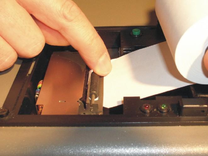
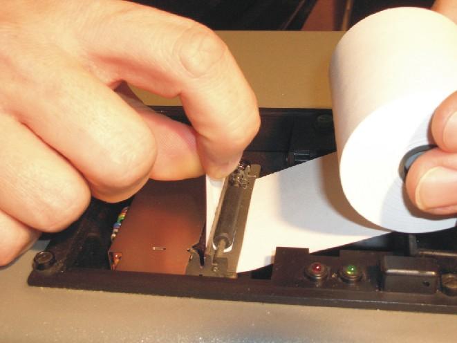
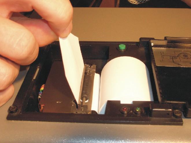
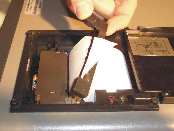
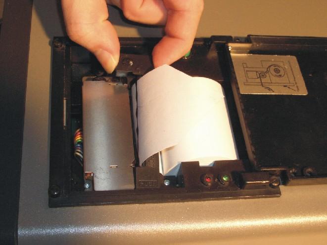
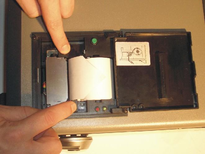

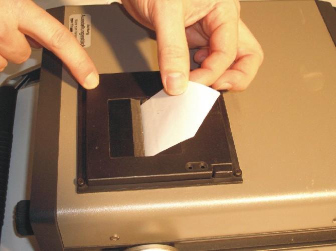
98 Performing maintenance HYDAC FILTER SYSTEMS GMBH en(us) Page 98/112
FMMP. FluidMonitoring Module Pressure. Operating and Maintenance Instructions. English (Translation of original manual) Documentation no.
 Documentation no.") FluidMonitoring Module Pressure Operating and Maintenance Instructions English (Translation of original manual) Documentation no.: 3360764 Safety Guidelines and Instructions Trademarks The trademarks of
FluidMonitoring Module Pressure Operating and Maintenance Instructions English (Translation of original manual) Documentation no.: 3360764 Safety Guidelines and Instructions Trademarks The trademarks of
FMMP Unit. FluidMonitoring Module Pressure Unit. Operating and Maintenance Instructions. English (translation of original instructions)
") FluidMonitoring Module Pressure Unit Operating and Maintenance Instructions English (translation of original instructions) Document No.: 3353921a Trademarks Trademarks The trademarks of other companies
FluidMonitoring Module Pressure Unit Operating and Maintenance Instructions English (translation of original instructions) Document No.: 3353921a Trademarks Trademarks The trademarks of other companies
FCU 1210 CAT FluidControl Unit Operating and Maintenance Instructions
 FCU 1210 CAT FluidControl Unit Operating and Maintenance Instructions English (translation of original instructions) Valid from firmware versions V 2.C2 / 2.40 up Document No.: 3278229i Trademarks Trademarks
FCU 1000 Series FluidControl Unit Operating and Maintenance Instructions
 FCU 1000 Series FluidControl Unit Operating and Maintenance Instructions English (Translation of original) Valid from firmware versions V 1.10 up Doc.: 3371346a / 2007-12-03 Trademarks The trademarks of
CSM 2000 Series. ContaminationSensor Module. Operating and Maintenance Instructions. English (translation of original instructions)
") ContaminationSensor Module Operating and Maintenance Instructions English (translation of original instructions) Dokument No.: 3211683h (from series no. 0002S02043K0000015) Trademarks Trademarks The trademarks
ContaminationSensor Module Operating and Maintenance Instructions English (translation of original instructions) Dokument No.: 3211683h (from series no. 0002S02043K0000015) Trademarks Trademarks The trademarks
Operating instructions Electrical switching facility pco
 Operating instructions Electrical switching facility pco from software version V1.33 on TABLE OF CONTENTS 1. Before you start... 4 1.1 Brief description... 4 1.2 Using this manual... 4 2. pco integrated
The Univentor 1250 Anaesthesia Unit
 THE UNIVENTOR 1200/1250 ANAESTHESIA UNIT The Univentor 1250 Anaesthesia Unit TABLE OF CONTENTS EDITION 1 Section 1 - WARRANTY & SERVICE 1.1. WARRANTY 2 1.2. DAMAGED SHIPMENTS 2 1.3. SERVICE 2 Section 2
OxyScan Graphic. Operating Instructions. UMS Micro-oxygen sensor 501. Microprocessor instrument
 OxyScan Graphic Operating Instructions UMS Micro-oxygen sensor 501 Microprocessor instrument Introduction Thank you for choosing the UMS Micro Oxygen Sensor 501 - a highly advanced product! Please read
Pegas 4000 MF Gas Mixer InstructionManual Columbus Instruments
 Pegas 4000 MF Gas Mixer InstructionManual Contents I Table of Contents Foreword Part I Introduction 1 2 1 System overview... 2 2 Specifications... 3 Part II Installation 4 1 Rear panel connections...
NB/NBR NITROGEN BOOSTER FOR AVIATION SERVICE
 NB/NBR NITROGEN BOOSTER FOR AVIATION SERVICE INSTALLATION, OPERATION & MAINTENANCE MANUAL INTERFACE DEVICES, INC. 230 Depot Road, Milford, CT 06460 Ph: (203) 878-4648, Fx: (203) 882-0885, E-mail: info@interfacedevices.com
Touch Screen Guide. OG-1500 and OG Part # T011
 Touch Screen Guide OG-1500 and OG-2000 Part # 9000000.T011 Effective 11/2010 External View Internal View 1. Transducer Banks 2. Oxygen Sensor 3. PLC These are the two manifolds with three (3) transducers
Instruction Manual Dräger MSI P7 and MSI P7 plus
 Dräger MSI GmbH Rohrstraße 32 58093 Hagen Tel.: +49-2331 / 9584-0 Fax: +49-2331 / 9584-29 e-mail: info@draeger-msi.de D 923; Edition 2011-01-01 Content 1. General Hints Page 4 2. The Instrument 2.1 Front
BUBBLER CONTROL SYSTEM
 BUBBLER CONTROL SYSTEM Description: The HDBCS is a fully automatic bubbler system, which does liquid level measurements in water and wastewater applications. It is a dual air compressor system with, air
OXY Integral. INTERCON ENTERPRISES INC Tel: Fax: Internet:
 OXY Integral INTERCON ENTERPRISES INC Tel: 800 665 6655 Fax: 604 946 5340 E-Mail: sales@intercononline.com Internet: www.intercononline.com Manual Integral 2006 1 INDEX 2-3 PREFACE 4 INTRODUCTION 5 Principle
Mounting and Operating Instructions EB 2558 EN. Self-operated Pressure Regulators. Type Pressure Build-up Regulator
 Self-operated Pressure Regulators Type 2357-31 Pressure Build-up Regulator with safety function and integrated excess pressure valve Type 2357-31 with non-return unit at port C Ports A and B with soldering
ACV-10 Automatic Control Valve
 ACV-10 Automatic Control Valve Installation, Operation & Maintenance General: The Archer Instruments ACV-10 is a precision automatic feed rate control valve for use in vacuum systems feeding Chlorine,
HumiSys HF High Flow RH Generator
 HumiSys HF High Flow RH Generator Designed, built, and supported by InstruQuest Inc. Versatile Relative Humidity Generation and Multi-Sensor System The HumiSys HF is a high flow version of the previously
BSS 2 Bottle Sampling System. Instruction manual Version 1.8
 BSS 2 Bottle Sampling System Instruction manual Version 1.8 Serial-No.:... Version-/Rev.-Date : 12.06.2012 Contents 1. General... 3 2. Safety Instructions... 4 3. Extent of Delivery... 5 4. Switch Panel...
MP15 Jockey Pump Controller
 Setup and Operating Instructions MP15 Jockey Pump Controller This manual provides general information, installation, operation, maintenance, and system setup information for Metron Model MP15 Jockey Pump
Stand-Alone Bubble Detection System
 Instruction Sheet P/N Stand-Alone Bubble Detection System 1. Introduction The Bubble Detection system is designed to detect air-bubble induced gaps in a bead of material as it is being dispensed. When
CONSOLE-320 ENGLISH. 230A: CONSOLE-320 with cable data output Item 230B: CONSOLE-320 with cable + wireless radio data output
 CONSOLE-320 Item 230A: CONSOLE-320 with cable data output Item 230B: CONSOLE-320 with cable + wireless radio data output Table of contents 1. INTRODUCTION...2 1.1 Power supply...2 1.2 Connections...2 1.3
92831 TEL: (714) FAX:
 FAX:") Document N0. 1800-03 Copyright 2010 Terra Universal Inc. All rights reserved. Revised Sept. 2010 Terra Universal, Inc. TerraUniversal.com 800 S. Raymond Ave. Fullerton, CA 92831 TEL: (714) 578-6000 FAX:
Document N0. 1800-03 Copyright 2010 Terra Universal Inc. All rights reserved. Revised Sept. 2010 Terra Universal, Inc. TerraUniversal.com 800 S. Raymond Ave. Fullerton, CA 92831 TEL: (714) 578-6000 FAX:
MANUAL DIRECT PURGE OPTION. UNION Instruments GmbH CWD2005 PLUS. General information, safety standards and regulations for direct purge option
 MANUAL DIRECT PURGE OPTION UNION Instruments GmbH CWD2005 PLUS General information, safety standards and regulations for direct purge option Version: V1.00 Stand: 24.03.2010 Union Instruments GmbH Zeppelinstr.
PROPORTIONING VALVE. Model 150 INSTRUCTION MANUAL. March 2017 IMS Company Stafford Road
 PROPORTIONING VALVE Model 150 INSTRUCTION MANUAL March 2017 IMS Company 10373 Stafford Road Telephone: (440) 543-1615 Fax: (440) 543-1069 Email: sales@imscompany.com 1 Introduction IMS Company reserves
RAM Operation Manual. Worldwide Manufacturer of Gas Detection Solutions
 RAM 4021 Operation Manual Worldwide Manufacturer of Gas Detection Solutions TABLE OF CONTENTS RAM 4021 For Your Safety... 2 Description.... 2 Setup Mode.... 2 Lights/Alarms.... 3 Operation.... 4 Calibration....
User Manual. Quantos Automated Dosing Liquid Module
 User Manual Liquid Module 1 Safety Information 1.1 Definition of warnings and symbols Signal Words WARNING for a hazardous situation with medium risk, possibly resulting in severe injuries or death if
RAM 4021 Operation Manual
 RAM 4021 Operation Manual Worldwide Manufacturer of Gas Detection Solutions TABLE OF CONTENTS RAM 4021 For your safety...3 Description...3 Set-up mode...4 Annunciator lights/alarms...4 Operation...5 Calibration...6
UBEC 1AT. AUTO TANK Fill System Installation, Operation, & Setup Instructions
 Document Number: XE-ATA5PM-R1A UBEC 1AT AUTO TANK Fill System 08899155 Installation, Operation, & Setup Instructions Rev170906-EB-FRC PHYSICAL: 1302 WEST BEARDSLEY AVE ELKHART, IN 46514 WWW.ELKHARTBRASS.COM
Pneumatic high-pressure controller Model CPC7000
 Calibration technology Pneumatic high-pressure controller Model CPC7000 WIKA data sheet CT 27.63 Applications Healthcare and avionics industry Industry (laboratory, workshop and production) Transmitter
RAM 4021-DPX Operation Manual
 RAM 4021-DPX Operation Manual Worldwide Manufacturer of Gas Detection Solutions TABLE OF CONTENTS ABL 4021-DPX / RAM 4021-DPX For Your Safety... 3 Description... 3 Setup Mode... 4 Lights/Alarms... 4 Operation...
Measurement accessories METPOINT OCV for the measurement in systems up to 40 bar
 EN - english Instructions for installation and operation Measurement accessories METPOINT OCV for the measurement in systems up to 40 bar Dear customer, Thank you for deciding in favour of the METPOINT
Supplementary Operator s Manual 42/24-14 EN Rev. 3
 Advance Optima Continuous Gas Analyzers AO2000 Series with Uras26, Magnos206, Caldos25, Caldos27 Designed per Category 3G for Measurement of Flammable Gases ( Safety Concept ) and Non-flammable Gases Supplementary
Roller AC Servo System
 Safely Instruction Roller AC Servo System HMI-15 User Manual Please read this manual carefully, also with related manual for the machinery before use the controller. For installing and operating the controller
RAM 4021-PR. Operation Manual. Worldwide Manufacturer of Gas Detection Solutions
 RAM 4021-PR Operation Manual Worldwide Manufacturer of Gas Detection Solutions TABLE OF CONTENTS RAM 4021-PR For Your Safety... 2 Description.... 2 Setup Mode.... 2 Lights/Alarms.... 3 Operation.... 4
ASE SOLVENT CONTROLLER INSTALLATION INSTRUCTIONS Dionex Corporation
 ASE SOLVENT CONTROLLER INSTALLATION INSTRUCTIONS 2000 Dionex Corporation Document No. 031277 Revision 03 April 2000 2000 Dionex Corporation All rights reserved worldwide. Printed in the United States of
Description. Measuring Device 3760XBI USP. Balancing
 Measuring Device 3760XBI Description 3760XBI comprises from a differential pressure unit with an integrated true differential pressure sensor for the exact measuring of both differential and static pressures
RAM Operation Manual
 RAM 4021-1 Operation Manual Worldwide Manufacturer of Gas Detection Solutions TABLE OF CONTENTS RAM 4021-1 For Your Safety... 2 Description... 2 Setup Mode... 3 Lights/Alarms... 3 Operation... 4 Calibration...
Nothing's as cool, as a freshwater pool. easychem 770 ORP and ph Controller for Pools and Spas with Timer Output for Pool Pump
 Page 1 of 6 TPS Australia - Quality hand-made instruments since 1968. Nothing's as cool, as a freshwater pool easychem 770 ORP and ph Controller for Pools and Spas with Timer Output for Pool Pump Automatic
FAULT CODE TROUBLESHOOTING INDEX
 FAULT CODE TROUBLESHOOTING INDEX 1. Display indicates Change Filters 2. Display indicates Drip Tray Full Continuous Alarm will Sound 3. Display indicates Cold Fault 4. Display indicates Hot Fault 5. Display
The HumiSys. RH Generator. Operation. Applications. Designed, built, and supported by InstruQuest Inc.
 The HumiSys RH Generator Designed, built, and supported by InstruQuest Inc. Versatile Relative Humidity Generation and Multi-Sensor System The new HumiSys with single or dual RH probes capabilities is
RAM Operation Manual. Worldwide Manufacturer of Gas Detection Solutions
 RAM 4021 Operation Manual Worldwide Manufacturer of Gas Detection Solutions TABLE OF CONTENTS RAM 4021 For Your Safety... 2 Description.... 2 Setup Mode.... 2 Lights/Alarms.... 3 Operation.... 4 Calibration....
Installation, Operation and Maintenance Instructions for Electronically Controlled Pressurisation Units
 Installation, Operation and Maintenance Instructions for Electronically Controlled Pressurisation Units Models: EPS Single Pump EPT Twin Pump EPS-HP EPT-HP Single Pump High Pressure Twin Pump High Pressure
PH01 Perfusion Cannula Manual
 PH01 Perfusion Cannula Manual Information in this document is subject to change without notice. No part of this document may be reproduced or transmitted without the express written permission of Multi
UNITY 2 TM. Air Server Series 2 Operators Manual. Version 1.0. February 2008
 UNITY 2 TM Air Server Series 2 Operators Manual Version 1.0 February 2008 1. Introduction to the Air Server Accessory for UNITY 2...2 1.1. Summary of Operation...2 2. Developing a UNITY 2-Air Server method
CCT-7320/ROC-2313 Reverse Osmosis Controller
 CCT-7320/ROC-2313 Reverse Osmosis Controller 1 General The instrument is a combined control instrument of a reverse osmosis controller and an on-line conductivity instrument. It can perform the operation
Operating Instructions in accordance with the Machines Directive 2006/42/EC
 Lubricating Equipment Metering Technology for Grease and Oil High Pressure Hydraulic Customised Developments Operating Instructions in accordance with the Machines Directive 2006/42/EC Compressed air filling
Operation Manual - PN A MENSOR MODEL 73 SHOP AIR BOOSTER
 Operation Manual - PN 0017946001 A MENSOR MODEL 73 SHOP AIR BOOSTER Mensor Model 73 Shop Air Booster System (750 psi Version) April 23, 2012 Trademarks / Copyright Mensor is a registered trademark of Mensor
TR Electronic Pressure Regulator. User s Manual
 TR Electronic Pressure Regulator Page 2 of 13 Table of Contents Warnings, Cautions & Notices... 3 Factory Default Setting... 4 Quick Start Procedure... 5 Configuration Tab... 8 Setup Tab... 9 Internal
Operating and maintenance manual Filter and reducing station Series / 1.0
 Operating and maintenance manual Filter and reducing station Series 961 04.2017 / 1.0 Original instructions ARCA Regler GmbH. All rights reserved. Cover picture background: Freepik.com ARCA Regler GmbH
SAPCON. User Manual. Capacitance Continuous Level Indicator. . Introduction. . General Description. . Principle of Operation. .
 User Manual Capacitance Continuous Level Indicator Comprehensive User s Manual. Introduction. General Description. Principle of Operation. Specifications. Connection Diagrams. Quick Calibration Chart.
Device overview. 6 Breathing circuit connection. Note: When the remote control foot pedal is connected, the manual switch is disabled.
 CoughAssist E70 Quick start guide 1 2 3 4 5 Device overview Starting therapy Modifying therapy settings Monitoring view and icons 6 7 Suggested guidelines for therapy Device menu Mask fitting 1 Device
Scoreboard Operator s Instructions MPC Control
 Scoreboard Operator s Instructions MPC Control Some features on the keyboard overlay may not be included on the particular model being operated. Since 1934 Retain this manual in your permanent files 1/21/2011
Change-Over Pressure Filter DFDK
 Change-Over Pressure Filter up to 8 l/min, up to 35 bar 3 6 4 6 4 8 33 5 66.x 66.x 99.x 3.x 3 3.x 64 3.x 396 3.x. TECHNICAL SPECIFICATIONS. FILTER HOUSING Construction The filter housings are designed
Instruction manual. for. high purity gas pigtails 200 bar / 300 bar
 Instruction manual for high purity gas pigtails 200 bar / 300 bar Contents Contents... 2 1. Preface... 3 1.1 Overview... 3 1.2 General... 3 1.3 Intended use... 4 1.4 Personnel requirements... 4 2. For
User Manual 1 P a g e Rev. V1.6-EN 11/08/2014
 User Manual 1 P a g e Rev. V1.6-EN 11/08/2014 Copyright Disclaimer Trademarks and patents Intended use Contact info 2011 Inflotrolix, Inc. This document may not be copied in whole or in part or otherwise
PRAHER PLC-MP AQUASTAR MANAUL 2009
 PRAHER PLC-MP AQUASTAR MANAUL 2009 1. Copyrights This Operating Manual contains copyright-protected information. All rights reserved to Praher Kunststofftechnik GmbH. This Operating Manual is designed
SPECIFICATIONS ATTENTION
 VPS 504 S06 Installation Manual - P/N 80122 - Ed. 01/09 VPS 504 S06 and S05 Valve Proving System Installation Instructions VPS 1 6 Gases Natural gas, air and other inert gases. NOT suitable for butane
Laboratory Mortar Mixer (Testing)
") TomTom-Tools GmbH Zelgli 20 8905 Arni info@tomtom-tools.com Switzerland www.tomtom-tools.com User Manual Version February 22, 2015 Laboratory Mortar Mixer (Testing) 1 Introduction The Laboratory Mortar
TomTom-Tools GmbH Zelgli 20 8905 Arni info@tomtom-tools.com Switzerland www.tomtom-tools.com User Manual Version February 22, 2015 Laboratory Mortar Mixer (Testing) 1 Introduction The Laboratory Mortar
Safety. Operating instructions Solenoid valve for gas VG 6 VG 15/10 DANGER. Contents WARNING CAUTION. Changes to edition 09.14
 15 Elster GmbH Edition 7.15 Translation from the German 519 D F NL I E DK S N P GR TR CZ PL RUS H www.docuthek.com Operating instructions Solenoid valve for gas VG VG 15/1 Contents Solenoid valve for gas
TorMinal. Operating instructions V OCE-Rev.L_EN
 TorMinal Operating instructions 1-138 3800-20310V001-112016-0-OCE-Rev.L_EN Table of contents General Information... 4 Symbols... 4 General safety instructions... 4 Safety information for batteries... 4
Mass Flow Controller (MFC) for Gases
 for Gases") Mass Flow Controller (MFC) for Gases Bypass MFC with capillary technology for nominal flow rates from 5 ml N /min to 15 l N /min Applicable for aggressive gases Compact design and digital communication
Mass Flow Controller (MFC) for Gases Bypass MFC with capillary technology for nominal flow rates from 5 ml N /min to 15 l N /min Applicable for aggressive gases Compact design and digital communication
Type 3709 Pneumatic Lock-up Valve. Translation of original instructions. Mounting and Operating Instructions EB 8391 EN
 Type 3709 Pneumatic Lock-up Valve Translation of original instructions Mounting and Operating Instructions EB 8391 EN Edition July 2017 Note on these mounting and operating instructions These mounting
THE UNIVENTOR 400 ANAESTHESIA UNIT
 THE UNIVENTOR 400 ANAESTHESIA UNIT TABLE OF CONTENTS EDITION 3 Section 1 - WARRANTY & SERVICE 1.1. WARRANTY 2 1.2. DAMAGED SHIPMENTS 2 1.3. SERVICE 2 Section 2 - INTRODUCTION 2.1. INTRODUCTION 3 Section
HUMOR 20. High-precision Humidity Calibrator HUMOR 20. Operation
 High-precision Humidity Calibrator The role of humidity calibrations that are accurate, reproducible, and documentable is becoming more and more important. ISO quality guidelines and regulations according
A4s Operation Manual
 A4s Operation Manual Safety Instruction Please read this manual carefully, also with related manual for the machinery before use the controller. For installing and operating the controller properly and
WATER CONTROL SYSTEM QUICK START
 SETTINGS MENU SYSTEM OPTIONS WATER LEVEL BAR GRAPH 3 DS SPRAY ON/OFF CS SPRAY ON/OFF BEACON WATER CONTROL SYSTEM QUICK START WWW.GFWORLDWIDE.COM +1 (208) 664-9291 SERVICE@GFWORLDWIDE.COM DISPLAY SCREEN
Mass Flow Controller (MFC) for Gases
 for Gases") Mass Flow Controller (MFC) for Gases Type 8713 can be combined with... Direct flow measurement by MEMS- Technology for nominal flow rates from 1 ml N /min to 8 l N /min (N 2 ) High accuracy and repeatability
Mass Flow Controller (MFC) for Gases Type 8713 can be combined with... Direct flow measurement by MEMS- Technology for nominal flow rates from 1 ml N /min to 8 l N /min (N 2 ) High accuracy and repeatability
Instructions for Use
 Select-380 T-Auto T-Auto Contents Page Instructions for Use Ref: 3.0 IFU 380 T-Auto Mar 18 2 Schematic layout of the doser 3 Quick-fit instructions 4 Description/Installation/Operation Pump tubes & Water
6900 Maintenance Instruction System Flush
 Equipment Required FA74005 Damper Drain Tube FA16005 Cover Removal Tool FA900005 Beaker 0.25 Litre FA900003 Solvent Cleaning Bottle FA940021 Syringe Polypropylene 50 ml as required FA999045 Gloves Latex
WF STEUERUNGSTECHNIK GMBH. INFORMATION and TECNICAL DESCRIPTION
 1 INFORMATION and TECNICAL DESCRIPTION 14 2 AIRLEADER Professional Compressor Management + Compressed Air Visualisation + Alarm Service Management + AIRLEADER - has been the effective answer for compressed
R E D I C O N T R O L S
 R E D I C O N T R O L S Operation & Maintenance Manual Portable Service Purger for Low Pressure Chillers Model: PSP-LP-1B For Refrigerants R-11, R-113, R-114 & R-123 & Other Similar Refrigerants File Literature
3 GALLON, OILLESS PANCAKE COMPRESSOR INSTRUCTIONS. Item #31289
 3 GALLON, OILLESS PANCAKE COMPRESSOR INSTRUCTIONS Item #31289 The EASTWOOD 3 GALLON, OILLESS PANCAKE COMPRESSOR, with an Integral Air Regulator, efficiently supplies all compressed air requirements for
MODEL 100 NITROGEN INFLATION CART
 MODEL 100 NITROGEN INFLATION CART Installation & Operation Information Branick Industries, Inc. 4245 Main Avenue P.O. Box 1937 Fargo, North Dakota 58103 REV120106 P/N: 81-0113 TABLE OF CONTENTS SAFETY
User Manual PTW-DensiX. D / Di/Zi
 User Manual PTW-DensiX D148.131.0/3 2005-05 Di/Zi General Information General Information The product bears the CE-mark "CE-0124" in accordance with the Council Directive 93/42/EEC about Medical Devices
SPECIFICATIONS APCEPH1
 APCEPH1 ph CONTROLLER SPECIFICATIONS APCEPH1 Input voltage 120 Volts AC Maximum amperage 14.5 amps @ 120 VAC ph Accuracy +/- 0.2 ph ph Control range Adjustable 4.5 8.5 ph Weight < 1 lbs Dimensions 3" x
CO 2. (R744) Service Station Presentation. Contents. Goals Basic functions Specification Recovery R477 Vacuum Charge Safety Other features Prototype
 Service Station Presentation. Contents. Goals Basic functions Specification Recovery R477 Vacuum Charge Safety Other features Prototype") (R744) Service Station Presentation Contents Goals Basic functions Specification Recovery R477 Vacuum Charge Safety Other features Prototype Page 1 (R744) Service Station Goals Usability Full automatic
(R744) Service Station Presentation Contents Goals Basic functions Specification Recovery R477 Vacuum Charge Safety Other features Prototype Page 1 (R744) Service Station Goals Usability Full automatic
Safety instructions and operating manual
 5-Master Safety instructions and operating manual TBF-PyroTec GmbH Lichterfelder Str. 5 A 21502 Geesthacht Tel.: + 49 (0)4152 157 9950 Fax: + 49 (0)4152 157 9951 Flame projector 5-Master Safety instructions
Siphon vessel / Priming aid
 Manufacturer: sera GmbH sera-straße 1 34376 Immenhausen Germany Tel.: +49 5673 999-00 Fax: +49 5673 999-01 info@sera-web.com Keep the operating manual for future use! Record the exact type and serial number
UsER manual for Watersens ph -REDOX
 UsER manual for Watersens -REDOX Cl 8 1 2 6 3 3 7 7 4 4 4 4 Parts List 1 Redox Probe 1 x 2 PH Probe 1 x 5 Tube Weight 2 x 6 Connection Valve 1 x chlorine 3 Chlorine and Pumps 2 x 7 Dosing Valve 2 x 5 5
ECL Comfort 110, application 131 (valid as of software version 2.00)
") Operating Guide ECL Comfort 110, application 131 (valid as of software version 2.00) English version www.danfoss.com How to navigate? Adjust temperatures and values. Switch between menu lines. Select /
Operating Guide ECL Comfort 110, application 131 (valid as of software version 2.00) English version www.danfoss.com How to navigate? Adjust temperatures and values. Switch between menu lines. Select /
Pneumatic high-pressure controller Model CPC7000
 Calibration technology Pneumatic high-pressure controller Model CPC7000 WIKA data sheet CT 27.63 Applications Automotive and avionics industry Industry (laboratory, workshop and production) Transmitter
Operation Manual Air Saver Unit ASV5000 Series
 9IM-V066-b Operation Manual Air Saver Unit ASV5000 Series Thank you for your choice of Kuroda Pneumatics LTDs product on this time. Please read this operation manual carefully and use the product correctly.
Innovative Vacuum for Automation. Operating Instructions Dust Filter STF P / STF-D P.
 Innovative Vacuum for Automation EN Operating Instructions Dust Filter STF P / STF-D P 30.30.01.00059/02 11.2014 www.schmalz.com Note These operating instructions were written in the German language. This
User's Manual. Heavy Duty Dissolved Oxygen Meter. Model
 User's Manual Heavy Duty Dissolved Oxygen Meter Model 407510 Introduction Congratulations on your purchase of Extech's Heavy Duty Dissolved Oxygen / Temperature Meter which simultaneously displays Dissolved
REASONS FOR THE DEVELOPMENT
 7 Series 7 Series +24VDC VDC OUTPUT MICROPROCESS. E P IN EXH OUT 7 Series 7 ø,8 8 7 Series 9 5 8 9 7 Series Display features The proportional regulator has a 3 /2 digit display and a three-pushbutton
OptiAir CA09 Pneumaticfluidizing
 En Operating instructions and spare parts list OptiAir CA09 Pneumaticfluidizing unit Translation of the original operating instructions Documentation OptiAir CA09 Pneumatic-fluidizing unit Copyright 2006
Race Screen: Figure 2: Race Screen. Figure 3: Race Screen with Top Bulb Lock
 Eliminator Competition Stand Alone Mode - Instruction Manual Main Menu: After startup, the Eliminator Competition will enter the Main Menu. Press the right/left arrow buttons to move through the menu.
ECONORESS ELECTRONIC EPS & EPT - ENHANCED PRESSURISATION SET INSTALLATION OPERATION & MAINTENANCE DOCUMENTATION
 ECONORESS ELECTRONIC EPS & EPT - ENHANCED PRESSURISATION SET INSTALLATION OPERATION & MAINTENANCE DOCUMENTATION OCT2010 STOKVIS ENERGY SYSTEMS 96R WALTON ROAD EAST MOLESEY SURREY KT8 0DL TEL: 020 87833050
DPC-30 DPC-100. Reference Manual
 DPC-30 DPC-100 Reference Manual 1. Introduction 1.1 Description The Martel DPC Digital Pneumatic Calibrator improves upon traditional dial gauge pneumatic calibrators. The Martel DPC improves accuracy,
Mass Flow Meter (MFM) for Gases
 for Gases") 873 Mass Flow Meter (MFM) for Gases Direct flow measurement by MEMS- Technology for nominal flow rates from 1 ml N /min to 8 l N /min (N 2 ) High accuracy Short response time Compact design and digital
873 Mass Flow Meter (MFM) for Gases Direct flow measurement by MEMS- Technology for nominal flow rates from 1 ml N /min to 8 l N /min (N 2 ) High accuracy Short response time Compact design and digital
6800 Maintenance Instruction System Flush Procedure
 Equipment Required FA74005 FA65318 FA900005 FA900003 Damper Drain Tube 6800 Cover Removal Tool Beaker 0.25 Litre Solvent Cleaning Bottle FA940021 Syringe Polypropylene 50 ml as required FA999045 Gloves
Pressure reducing valve, pilot operated
 Pressure reducing valve, pilot operated RE 26928/09.07 Replaces: 10.97 1/8 Type 3DR Size 16 Component series 5X Maximum operating pressure 250 bar Maximum flow 220 l/min H5844 Table of contents Content
Instructions for Assembly, Installation, and Operation of the Gas Addition Kit Accessory with the CEM Discover Systems
 Corporation Issued: 5/09 P/N: 600104 Rev. 2 Instructions for Assembly, Installation, and Operation of the Gas Addition Kit Accessory with the CEM Discover Systems The Gas Addition Accessory permits the
AUTOMATIC HOSE TEST UNIT, TYPE SPU
 VALVES AND FITTINGS UP TO 14,000 BAR TEST AND CONTROL EQUIPMENT H IGH PRESSURE TECHNOLOGY AUTOMATIC HOSE TEST UNIT, TYPE SPU Pressure range from 1 up to 10,000 bar User-friendly touch panel operation HIGH-PRESSURE
Operating instructions Safety Rope Emergency Stop Switches ZB0052 / ZB0053 ZB0072 / ZB0073
 Operating instructions Safety Rope Emergency Stop Switches UK ZB0052 / ZB0053 ZB0072 / ZB0073 7390878 / 02 03 / 2011 Contents 1 Safety instructions...3 2 Installation / set-up...4 2.1 Applications...4
User Manual MFCS TM -EZ
 User Manual MFCS TM -EZ Version 6A_December 2016 1. INTRODUCTION 5 2. GENERAL INFORMATION 6 2.1 General functioning 6 2.2 Different MFCS TM 6 3. PACKAGE CONTENT 8 4. MFCS TM -EZ DESCRIPTION 9 5. CONNECTIONS
3-Way Safety Block DSV
 3-Way Safety Block DSV DSV 10 - M DSV 10 - M - T-ball DSV 10 - EY 1. Description 1.1. GENERAL The 3-way safety block is used to shut off and discharge hydraulic accumulators or consumers. It complies with
Operating Instructions Part No
 DIGITAL AUTOMATIC TYRE INFLATOR Operating Instructions Part No. 11.0578 Thank you for selecting this Jamec Pem Automatic Tyre Inflator. Please read this manual before carrying out any installation or service
BS ml Bottle Sampling Unit
 BS500 500ml Bottle Sampling Unit User Guide www.mpfiltri.co.uk 200.307-EN Covers Model Numbers BS500 SAFETY WARNING Hydraulic systems contain dangerous fluids at high pressures and temperatures. Installation,
Instruction Manual Contact Pressure Vacuum Gauge
 MS10 Instruction Manual Contact Pressure Vacuum Gauge Table of Contents 1. Safety Instructions 2. Intended Applications 3. Product Description and Functions 4. Installation 5. Commissioning 6. Maintenance