GORSKI G2000SS DIVING HELMET TECHNICAL MANUAL
|
|
|
- Natalie Phillips
- 6 years ago
- Views:
Transcription

1 GORSKI G2000SS DIVING HELMET TECHNICAL MANUAL REVISION 06/11
2 COPYRIGHT NOTICE This manual is copyrighted, all rights reserved. It may not, in whole or in part, be copied, photocopied, reproduced, translated, or reduced to any electronic medium or machine readable form without prior consent in writing from Aqua Lung America, Inc AQUA LUNG AMERICA, Inc. All rights reserved. 2
3 TABLE OF CONTENTS I. SAFETY INFORMATION.. 4 II. WARRANTY INFORMATION.. 4 III. HELMET SET-UP AND OPERATION IV. HELMET MAINTENANCE AND PARTS LISTS V. STEP-BY-STEP ASSEMBLY INSTRUCTIONS A. SECOND STAGE REGULATOR B. FREE FLOW / EXHAUST VALVE C. MANIFOLD 14 D. DEFOGGER.. 15 E. ORAL-NASAL MASK.. 16 F. NOSE-CLEARING DEVICE 18 G. FRONT PORT ASSEMBLY 19 H. COMMUNICATIONS.. 20 I. HEAD LINER. 21 J. NECK RETAINER AND LOCKING SYSTEM K. HELMET FINAL ASSEMBLY 24 L. NECK DAM ASSEMBLY VI. APPENDICES EXPLODED PARTS DIAGRAMS A. APPENDIX A MAIN ASSEMBLIES. 31 B. APPENDIX B INNER COMPONENTS 32 C. APPENDIX C MANIFOLD BODY ASSEMBLY. 33 D. APPENDIX D FREE FLOW VALVE ASSEMBLY. 34 E. APPENDIX E SECOND STAGE REGULATOR ASSEMBLY 35 F. APPENDIX F NOSE CLEARING DEVICE ASSEMBLY. 36 G. APPENDIX G NECK DAM ASSEMBLY 37 H. APPENDIX H WELDING SHIELD KIT I. APPENDIX I DOUBLE EXHAUST KIT J. APPENDIX J ANNUAL SERVICE KIT VII. SPARE PARTS CROSS-REFERENCE LIST
4 I. SAFETY INFORMATION THE G2000SS HELMET SHOULD BE USED BY CERTIFIED AND PROPERLY TRAINED DIVERS ONLY. Recommended Umbilical Gas Supply Pressure psi OBP WARNINGS Supply pressure at or below 90 psi OBP may lead to CO2 build-up inside the helmet. Supply pressure above 200 psi OBP may cause the regulator to free flow. The G2000SS helmet is not cleaned or lubricated for oxygen service. Using the helmet with oxygen percentages above 50% by volume may lead to serious injury or death. CAUTION - CONTAMINATED WATER DIVING The helmet should not be used for contaminated water diving (CWD) when only a single exhaust is fitted. A double exhaust adapter kit is available for CWD. When used for CWD with double exhaust fitted, the free flow valve must be open and properly adjusted at all times throughout the dive, as positive pressure inside helmet must be maintained. II. WARRANTY INFORMATION The manufacturer warrants every new helmet to be free from defects in workmanship for a period of ninety (90) days from date of purchase. Parts covered under the Warranty: This warranty covers all metal parts. Parts NOT covered under the Warranty: This warranty does not cover any rubber parts, communications components, headliners, or chrome plating. Due to the electrolytic nature of underwater cutting and welding, chrome plating cannot be warranted when the diver engages in these activities. The Warranty becomes null and void if: The product has been modified without consent of Aqua Lung America, Inc. The product has been misused, damaged or put into situation not intended for products service or if the product has not been correctly maintained according to the G2000SS Diving Helmet Technical Manual. 4
5 III. HELMET SET-UP AND OPERATION SET-UP PROCEDURES Testing the Check Valves : The helmet is equipped with two check valves, one for main air and the other for emergency air. Each check valve should be checked prior to connecting a hose. To check each check valve, the free flow valve must be open and air must be pulled from the check valve to verify that it is closed. The hoses can be attached only after verifying that the check valves are properly functioning. Testing the Emergency Gas Supply (EGS) : After the diver has verified a proper seal of the helmet on his head and the main air is bled from the hose, the diver must turn his emergency (bailout) cylinder valve on and use the bailout regulator to breath inside the helmet. The emergency cylinder valve must then be shut leaving the hose pressurized. The EGS must ALWAYS be turned off at the cylinder valve while diving. CHECKLISTS The following checklists are provided to assist all users and technicians: User: Daily Checklist Pre-Dive Checklist In-Water Checklist for Supervisor Post Dive Checklist Technician: Monthly Inspection & Maintenance Checklist Annual Inspection & Maintenance Checklist UMBILICAL GAS SUPPLY PRESSURES The second stage regulator is designed to provide optimum performance at a driving pressure/over Bottom Pressure (OBP) of 170 psig (11.7 bar). During diving operations the diver s umbilical supply pressure must be maintained between 140 psig and 170 psig (9.65 bar to 11.7 bar) OBP at all times. The OBP must not drop below 90 psig (6.2 bar) at any time: OBP at or below 90 psig (6.2 bar) may lead to CO2 build-up inside the helmet - if this occurs the diver must reduce his workload to avoid exhaustion. The second stage regulator and manifold have a maximum design pressure of approx 200 psig (13.8 bar) over-bottom. 5
6 IV. HELMET MAINTENANCE & PARTS LISTS (1) IMPORTANT NOTES This manual provides factory prescribed procedures for the correct service and repair of the G2000SS diving helmet. It is strongly recommended that all repairs are completed in accordance with this manual. The procedures outlined within this manual are to be performed only by personnel who have received factory authorized training and are certified as a G2000SS service technician. If you do not completely understand all of the procedures outlined in this manual, contact Aqua Lung / Gorski to speak directly with a Technical Advisor before proceeding any further. SCHEDULED SERVICE 1. The G2000SS diving helmet is subject to annual service regardless of usage. 2. The Annual Service Kit (P/N ) contains all parts that are replaced annually. See Appendix J for details of this kit. 3. The Overhaul & Maintenance (Annual) Checklist must be followed for annual service. LUBRICATION Helmets used for air diving or diving with gas containing oxygen percentages less than 50% may be lubricated with food grade silicone such as Dow Corning 111 or equivalent. All O-rings must be lubricated prior to assembly. CAUTION Do NOT lubricate diaphragms or one-way valves. Lubricant attracts dirt and debris and may cause the item to malfunction. COMPONENT INTERCHANGEABILITY The G2000SS is designed specifically so that all new or modified assemblies are interchangeable with, and may be retro-fitted to, all existing helmets. This enhances product support. Certain step-by-step procedures in this manual show older assemblies this demonstrates component interchangeability and makes no difference to helmet performance or functionality. 6
7 IV. HELMET MAINTENANCE & PARTS LISTS (2) GENERAL GUIDELINES 1. In order to correctly perform the procedures outlined in this manual, it is important to follow each step exactly in the order given. Read over the entire manual to become familiar with all procedures before attempting to service or repair the G2000SS helmet. 2. Keep the manual open beside you for reference while performing each procedure. Do not rely on memory. 3. All service and repair should be carried out in a work area specifically set up and equipped for the task. Adequate lighting, cleanliness, and easy access to all required tools are essential for an efficient repair facility. 4. As each unit is disassembled, reusable components should be segregated and not allowed to intermix with non-reusable parts. Delicate parts, including inlet fittings and crowns which contain critical sealing surfaces, must be protected and isolated from other parts to prevent damage during the cleaning procedure. 5. Use only genuine Aqua Lung / Gorski parts provided in the service kits. DO NOT attempt to substitute any part with another manufacturer s, regardless of any similarity in shape or size. Substitution with other manufacturer s parts constitutes an after-market modification of the product, and renders all warranties null and void. 6. Do not attempt to reuse mandatory replacement parts under any circumstances, regardless of the amount of use the product has received since it was manufactured or last serviced. PART NUMBERS FOR PART NUMBERS REFER TO THE G2000SS PARTS LIST IN THE APPENDICES LOCATED AT THE BACK OF THE MANUAL. All Gorski part numbers have been assigned Aqua Lung (AQA) part numbers a cross-reference list is at the back of this manual. Main Assemblies. Inner Components..... Manifold Body Assembly.. Free Flow Valve Assembly... Second Stage Regulator Assembly... Nose Clearing Device Assembly Neck Dam Assembly. Double Exhaust Valve Kit Welding Shield Kit Appendix A Appendix B Appendix C Appendix D Appendix E Appendix F Appendix G Appendix H Appendix I 7
8 V. STEP-BY-STEP ASSEMBLY INSTRUCTIONS NOTES ON DISASSEMBLY AND ASSEMBLY 1. Disassembly procedures are the reverse of assembly. 2. All components must be clean and fully serviceable prior to assembly. 3. All O-rings must be lubricated prior to assembly. 8


9 SECOND STAGE REGULATOR (1) Step 1: Place Diaphragm into Housing. Do NOT lubricate the Diaphragm Step 2: Diaphragm in the Diaphragm Housing Step 3: Install the Purge Button onto the Diaphragm Cover Step 4: Purge Button installed Step 5: Install the Diaphragm Cover onto the Housing Step 6: Compress the Cover and install the Snap Ring Step 7: Ensure that the Snap Ring sits securely in the inside groove Step 8: Install Flapper Valve on rear of Housing. Do NOT lubricate the Flapper Valve Step 9: Install the Snap Ring Step 10: Lubricate and install O-ring on outside of Housing Step 11: Diaphragm Housing complete 9


10 SECOND STAGE REGULATOR (2) Step 12: Lubricate and install small O-ring on Main Body Step 13: O-ring installed on Main Body Step 14: Lubricate and install small O-ring LP Valve Assembly Step 15: O-ring installed on LP Valve Assembly Step 16: Second Stage Regulator components ready for assembly Step 17: Set the Valve rotate sleeve so right edge of cut aligns with center line of Lever Step 18: Install LP Valve Assembly into Main Body Step 19: Install Connecting Ring and tighten by hand Step 20: Connecting Ring securely installed Step 21: Use flat blade screwdriver for adjustment Step 22: Hold in vertical position 10 Step 23: Adjust until Lever end is level with housing top edge

")

11 SECOND STAGE REGULATOR (3) Step 24: Insert Lever into Diaphragm tube: tighten by hand Step 25: Diaphragm Housing installed on Main Body Note: Maintenance procedures for the Low Pressure (LP) Valve Assembly - circled in the photo below - are contained in the separate Excerpt from Cyclone 5000 Regulator Manual. 11

12 FREE FLOW / EXHAUST VALVE (1) 12

13 FREE FLOW / EXHAUST VALVE (2) 13


 into")

 to first port Step")
 to the 2nd port")

14 MANIFOLD Step 1: All manifold parts Step 2: Insert screen into the manifold. Failure to install may cause debris to block the flow of gas to the diver. Step 3: Line up screen with the end of threads Step 4: Screw plug (with O-ring) to the manifold Step 5: Tighten the plug with a socket wrench to a snug fit Step 6: Screw Scuba plug (with O-ring) to the auxiliary port Step 7: Tighten Scuba plug with an Allen wrench until snug Step 8: Screw check valve (with Teflon tape) into the first port Step 9: Screw check valve (with Teflon tape) into the 2nd port Step 10: Screw Scuba hose fitting (with Teflon tape) to first port Step 11: Screw hose fitting (with Teflon tape) to the 2nd port Step 12: Tighten all pipe threads securely with a socket wrench 14


15 DEFOGGER Step 1: Two parts of Defogger, lower and upper unit Step 2: Insert lower unit over the Free Flow Exhaust Valve body Step 3: Push lower unit until it stops Step 4: Line up upper unit with the lower unit Step 5: Slide upper unit over the bracket of the lower unit 15


 Valve and")


16 ORAL-NASAL MASK (1) CAUTION The Head Liner and Oral-Nasal Mask must be used at all times when diving. The Head Liner ensures that the Oral-Nasal Mask maintains a good fit on the diver s face and reduces dead space in the helmet this helps to prevent CO2 build-up. Step 1: Oral-Nasal Mask with Flapper (one-way) Valve and Valve Housing Step 2: Line up and install Valve in the Valve Housing. Do NOT lubricate the valve. Step 3: Oral-Nasal valve assembly Step 4: Insert valve assembly into the pocket on the left side of the Oral-Nasal Mask Step 5: Outside view of the correctly-installed Flapper Valve and Valve Housing Step 6: Insert Second Stage Regulator into the helmet Note: Flapper Valve must be installed on the inside of the Oral-Nasal Mask. If reversed it could cause serious problems including injury or death of the diver Step 7: Install Regulator Cover and tighten all screws to a snug fit with a Phillips screwdriver Step 8: Install Microphone in the right pocket of the Oral-Nasal Mask 16 Step 9: Point microphone wire downwards

 in the helmet")


17 ORAL-NASAL MASK (2) Step 10: Install Oral-Nasal Mask onto the regulator mouthpiece Step 11: Install Nose Clearing Device (NCD) in the helmet Step 12: Secure NCD knob on the shaft. Ensure that it is snug Step 13: Always check before diving to ensure that no threads are visible in order to prevent loosing the knob Step 14: Inside view of installed Oral-Nasal Mask assembly 17
")
18 NOSE-CLEARING DEVICE (NCD) 18

19 FRONT PORT ASSEMBLY 19
")


20 COMMUNICATIONS Note: The Communications System is designed and built by Ocean Technology Systems (OTS) specifically for the G2000SS Helmet. Step 1: Breakdown of Comms Assembly parts Step 2: Install and fasten all terminals to the internal posts Step 3: Install Microphone in the right pocket of the Oral-Nasal Mask Step 4: Microphone installed in Oral-Nasal Mask Step 5: Install L and R Speakers with the long wire on the left side Step 6: Place Left Speaker in left pocket of Head Liner Step 7: Place Right Speaker in right pocket of Head Liner Notes: Step 8: Communications System installed NOTE: 4-wire Communications Bulkhead with blanking cap installed. 1. The Helmet is fitted with a 2-wire comms system (using posts) as standard. 2. The Helmet may also be fitted with a 4-wire system using the Communications Bulkhead. The bulkhead is a standard feature (2011 onwards) and, if not used, is fitted with a blanking cap. 20


21 HEAD LINER CAUTION The Head Liner and Oral-Nasal Mask must be used at all times when diving. The Head Liner ensures that the Oral-Nasal Mask maintains a good fit on the diver s face and reduces dead space in the helmet this helps to prevent CO2 build-up. Step 1: Cut Velcro tape into 4 pieces, approx 2in x 1in each Step 2: Round off the corners on 2 pieces of Velcro as shown Step 3: Stick Velcro tabs onto both front sides of the helmet Step 4: Stick Velcro tabs onto both rear sides of the helmet Step 5: Head Liner Step 6: Line up Head Liner as shown Step 7: Place Left Speaker in left pocket of Head Liner Notes: Step 8: Place Right Speaker in right pocket of Head Liner Step 9: Head Liner installed (no Oral-Nasal Mask fitted yet) 1. The Head Liner may be washed by hand or machine. 2. Recommended Velcro: Industrial Strength, Sticky Bask Tape, Waterproof. 21
 of the neck")


22 NECK RETAINER AND LOCKING SYSTEM (1) Note: This version (MOD1) of the neck retainer and locking system was introduced in For the original version refer to previous editions of the helmet Technical Manual. Step 1: Breakdown of Locking System parts Note: There are Left and Right Latch Catch assemblies Step 2: Insert Latch into corresponding Latch Base (i.e. L or R) Step 3: Latch inserted in Latch Base Step 4: Fit Latch Spring over shaft of Latch Step 5: Fit Latch Spring Washer onto Latch Spring Bolt Step 6: Insert Bolt and Washer into shaft of Latch Step 7: Tighten Latch Spring Bolt using an Allen wrench until snug Step 8: Fit assembled Latch Base assembly onto correct side of helmet Step 9: Fit Lock Washer onto Latch Bolt 22
 of the neck retainer and")


23 NECK RETAINER AND LOCKING SYSTEM (2) Note: This version (MOD1) of the neck retainer and locking system was introduced in For the original version refer to previous editions of the helmet Technical Manual. Step 10: Insert Latch Bolt and Washer through helmet into Latch Base assembly Step 11: Tighten Latch Bolt using an Allen wrench until snug Step 12: Repeat the procedure for the other Latch. Step 13: Test the operation of each Latch assembly Step 14: Check condition of Neck Retainer Step 15:Fit Neck Retainer to hinge at rear of helmet using Neck Retainer Bolt and Neck Retainer Nut. Tighten using wrench until snug. Note: Ensure that Neck Retainer moves freely. Step 16: Ensure that Neck Retainer rand Locking System mates correctly 23
")
24 HELMET FINAL ASSEMBLY (1) 24
")
25 HELMET FINAL ASSEMBLY (2) 25
")
26 HELMET FINAL ASSEMBLY (3) 26
27 HELMET FINAL ASSEMBLY (4) 27

28 HELMET FINAL ASSEMBLY (5) 28 (Oral-Nasal Mask not installed)


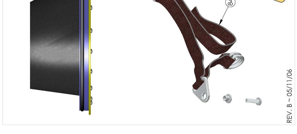
29 NECK DAM ASSEMBLY Note: The above photographs show the old, pre-2011, Neck Retainer. The current Neck Retainer MOD1, with Neck Dam in place, is shown below. Step 1: Neck Retainer MOD1 Step 2: Neck retainer MOD1 with right Latch Catch open Quad Ring Installation: Step 1: Lightly Lubricate Quad Ring and install in groove Step 2: Quad Ring installed 29
30 VI. APPENDICES - EXPLODED PARTS DIAGRAMS IMPORTANT NOTE All Gorski part numbers have been assigned Aqua Lung (AQA) part numbers a cross-reference list is at the back of this manual. Appendix A Appendix B Appendix C Appendix D Appendix E Appendix F Appendix G Appendix H Appendix I Appendix J Main Assemblies Inner Components Manifold Body Assembly Free Flow Valve Assembly Second Stage Regulator Assembly Nose Clearing Device Assembly Neck Dam Assembly Double Exhaust Valve Kit Welding Shield Kit Annual Service Kit 30

31 APPENDIX A MAIN ASSEMBLIES 31


32 APPENDIX B INNER COMPONENTS 32

33 APPENDIX C MANIFOLD BODY ASSEMBLY 33
34 APPENDIX D FREE FLOW VALVE ASSEMBLY 34

35 APPENDIX E SECOND STAGE REGULATOR ASSEMBLY 35

36 APPENDIX F NOSE CLEARING DEVICE ASSEMBLY 36


37 APPENDIX G NECK DAM ASSEMBLY 37

38 APPENDIX H WELDING SHIELD KIT (P/N ) 38


39 APPENDIX I DOUBLE EXH AUST KIT (P/N ) 39
 INSTALLATION INSTRUCTIONS (1)")


40 APPENDIX I DOUBLE EXH AUST KIT (P/N ) INSTALLATION INSTRUCTIONS (1) This procedure is to be performed only by personnel who have received appropriate training. If you do not completely understand all of the procedure, contact Aqua Lung / Gorski to speak directly with a Technical Advisor before proceeding any further. Step 1: Unscrew Free Flow Knob Step 2: Remove Knob, Spring and Nut Step 3: Unscrew Valve Exhaust Cover screws Step 4: Remove Valve Exhaust Cover Step 5: Parts Breakdown for Double Exhaust conversion Step 6: Place Exhaust Bushing over Valve Stem and Bonnet Step 7: Exhaust Bushing installed Step 8: Place Exhaust Seat over Bushing Step 9: Place Flapper Valve onto the Seat. Do NOT lubricate 40
 INSTALLATION INSTRUCTIONS (2) This")


41 APPENDIX I DOUBLE EXH AUST KIT (P/N ) INSTALLATION INSTRUCTIONS (2) This procedure is to be performed only by personnel who have received appropriate training. If you do not completely understand all of the procedure, contact Aqua Lung / Gorski to speak directly with a Technical Advisor before proceeding any further. Step 10: Place all Spacer Rings onto the Seat Step 11: Spacer Rings in place Step 12: Place Valve Exhaust Cover on top of Spacer Rings Step 13: Insert all Screws and run in by hand Step 14: Tighten Screws using a Phillips screwdriver until snug Step 15: Replace Knob, Spring and Nut Step 16: Tighten Nut until snug Step 17: Double Exhaust installed 41
42 APPENDIX J ANNUAL SERVICE KIT (P/N ) All Gorski part numbers have been assigned Aqua Lung (AQA) part numbers. The individual parts in the Annual Service Kit are labeled with AQA part numbers. The Location No. (column E) is provided to assist with correct parts identification and refers to the relevant Exploded Parts Diagram (Appendices A thru G) A B C D E New AQA Part No Gorski Part No Item Description Qty per Kit Location No SS-0007 Nut, Neck Retainer SS-0018 O-Ring, Face Port SS-0027 O-Ring, Swagelok Connector SS-0034 Valve, Flapper, Inhalation SS-0039 O-Ring, Manifold Plug SS-0042 O-Ring, Manifold Connector SS-0045 Gasket, Manifold SS-0046 O-Ring, Manifold SCUBA Plug SS-0053 O-Ring, Exhaust (Small) SS-0054 O-Ring, Exhaust (Large) SS-0058 Washer, Copper SS-0060 O-Ring, Stem, Free Flow Valve SS-0067 O-Ring, Regulator Body, Small SS-0069B O-Ring, Valve Seat, Regulator 1 See Note SS-0069C Plate, Rubber, Valve Piston, Regulator 1 See Note SS-0072 O-Ring, Nose Clearing Device (NCD) 2 72 Note: These parts are located inside the LP Valve Assembly. 42
43 VII. SPARE PARTS CROSS-REFERENCE LIST All Gorski part numbers have been assigned Aqua Lung (AQA) part numbers please use this cross-reference list when ordering spare parts. NOTE: ALL PARTS SHOULD BE ORDERED USING THE AQA P/N Gorski P/N Description AQA P/N G2000SSDH Helmet Complete, Gorski SS-001 Shell, Helmet SS-005 Retainer, Neck, Original SS-006 Bolt, Neck Retainer SS-007 Nut, Neck Retainer SS-009 Spring, Pull Pin SS-012 Nut, Knob SS-013 Spring, Knob SS-014 Knob, Free Flow SS-015 Screw SS-016 Cover, Valve Exhaust SS-017 Cover, Regulator SS-018 O-Ring SS-019 Plate, Face SS-020 Retainer, Port SS-021 Screw SS-022 Post, Communication SS-023 Bulkhead, Communications SS-023A Plug (spare), Bulkhead, Communications SS-024 Tube, Connecting SS-025 Block, Tubing SS-026 Connector, Swagelok SS-027 O-Ring SS-028 Train, Defogger SS-029 Barrel, Free Flow SS-032 Cup, Oral Nasal SS-033 Housing, Inhalation Valve SS-034 Valve, Inhalation Flapper SS-036 Liner, Head SS-037 Body, Manifold SS-038 Plug, manifold SS-039 O-Ring SS-040 Screen SS-041 Insert, Manifold Connecting SS-042 O-Ring SS-043 Screw SS-044 Screw SS-045 Gasket, manifold SS-046 O-Ring SS-047 Plug, SCUBA SS-048 Valve, Check
44 1SS-049 Fitting, SCUBA SS-050 Fitting, Hose SS-051 Cap, Fitting SS-052 Body, Free Flow Exhaust Valve SS-053 O-Ring SS-054 O-Ring SS-055 Valve, Flapper Exhaust SS-056 Ring, Snap Flapper Valve SS-057 Seat, Free Flow Valve SS-058 Washer, Copper SS-059 Stem, Free Flow Valve SS-060 O-Ring SS-061 Washer, Teflon SS-062 Valve, Free Flow Bonnet SS-063 Cover, Diaphragm SS-0063A Button, Purge SS-064 Ring, Snap Cover SS-065 Diaphragm, Second Stage SS-066 Housing, Second Stage Diaphragm SS-067 O-Ring SS-068 Body, Second Stage Main SS-069 Assembly, Valve SS-0069A Seat, Valve SS-0069B O-Ring SS-0069C Plate, Rubber SS-0069D Piston, Valve SS-0069E Spring SS-0069F Housing, Valve SS-0069G Pin, Lever SS-0069H Sleeve, Ejector SS-0069I Device, Operating SS-0070 Spring, Connecting SS-0071 Knob, NCD SS-0072 O-Ring SS-0073 Stem, NCD SS-0074 Pad, Metal Nose SS-0075 Pad, Nose Neoprene SS-0076 Ring, Quad SS-0077 Ring, Neck Upper SS-0078 Seal, Neck SS-0079 Ring, Neck Bottom SS-0080 Screw SS-0081 Screw SS-0082 Bushing SS-0083 Buckle, Strap SS-0084 Stripe, Nylon SS-0085 Body, Welding Shield SS-0086 Lens, Welding SS-0087 Bracket, Lens Holding SS-0088 Gasket, Welding Lens
45 1SS-0089 Screw SS-0090 Hinge, Welding Lens SS-0091 Screw SS-0092 Screw SS-0093 Spring, Welding Shield SS-0094 Screw SS-0095 Bushing, Dual Exhaust SS-0096 Seat, Dual Exhaust SS-0097 Ring, Spacer SS-0098 Screw n/a Kit, Welding Shield n/a Neck Ring Assembly n/a Set, Communication n/a Second Stage, Cyclone n/a Bracket, Light/Camera n/a Kit, Annual Service n/a Locking System n/a Kit, Double Exhaust n/a Kit, Free-Flow, Gorski Helmet SS-0099 Bolt, Latch SS-0100 Retainer, Neck, MOD SS-0101 Base, Latch, Left SS-0102 Base, Latch, Right SS-0103 Latch, Left SS-0104 Latch, Right SS-0105 Washer, Latch Spring SS-0106 Bolt, Latch Spring 1SS-0107 O-Ring 1SS-0108 Cap & Ferrules, Comm. Bulkhead 45

 597.4900 www.aqualung.")
46 GORSKI G2000SS DIVING HELMET TECHNICAL MANUAL Aqua Lung America, Inc Cousteau Court, Vista, CA Tel: (760) Fax: (760)
GORSKI G2000SS DIVING HELMET
 GORSKI G2000SS HELMET TECHNICAL MAINTENANCE MANUAL GORSKI G2000SS DIVING HELMET Rev. 8/12 www.aqualung.com/militaryandprofessional 2 Gorski G2000SS Diving Helmet Technical Manual COPYRIGHT NOTICE This
APPENDIX A MAIN ASSEMBLIES
 32 Gorski G2000SS Diving Helmet Technical Manual APPENDIX A MAIN ASSEMBLIES MANIFOLD BODY ASM SEE APPENDIX C 25 ft.lbs (34 Nm) 22 SS Blank Plug INNER 90 in.lbs COMPONENTS (10 Nm) INNER COMPONENTS SEE APPENDIX
AQUA LUNG G3000SS HELMET OPERATIONS & MAINTENANCE MANUAL
 AQUA LUNG G3000SS HELMET OPERATIONS & MAINTENANCE MANUAL Rev. 5/18 2 Aqua Lung G3000SS Diving Helmet Operations & Maintenance Manual COPYRIGHT NOTICE This manual is copyrighted, all rights reserved. It
Contents. Stainless Steel Side Block. 1.1 Separating the Side Block. Stainless Steel Side Block Reassembly of. Assembly from the Helmet Shell
 Separating the Side Block Assembly from the Helmet Shell Contents SSB-1 SSB-3 SSB-5 SSB-5 SSB-7 1.1 Separating the Side Block Assembly from the Helmet Shell 1.2 Side Block Assembly Replacement 1.3 Defogger
( SC) NOTE: KMDSI strongly recommends that all repairs be performed by trained Personnel.
 NOTE: KMDSI strongly recommends that all repairs be performed by trained Personnel.") KIRBY MORGAN SUPERLITE DEEP SEA DIVING HELMET MODELS 17 A/B, 17C, 17K, & KM 37, KM 47, KM 57, KM 77 & KM 97 MONTHLY INSPECTION AND MAINTENANCE CHECKLIST Appendix A2.2 (10-2-2016 SC) This inspection is
KIRBY MORGAN SUPERLITE DEEP SEA DIVING HELMET MODELS 17 A/B, 17C, 17K, & KM 37, KM 47, KM 57, KM 77 & KM 97 MONTHLY INSPECTION AND MAINTENANCE CHECKLIST Appendix A2.2 (10-2-2016 SC) This inspection is
DRAFT 12/17/03 KMB 18/28 (BANDMASK) OVERHAUL, MAINTENANCE, AND INSPECTION CHECKLIST APPENDIX A
 OVERHAUL, MAINTENANCE, AND INSPECTION CHECKLIST APPENDIX A") KMB 18/28 (BANDMASK) OVERHAUL, MAINTENANCE, AND INSPECTION CHECKLIST APPENDIX A2.1 12-17-03 THIS INSPECTION AND MAINTENANCE MUST BE PERFORMED AT LEAST ANNUALLY AND AS DICTATED BY CONDITION REVEALED DURING
KMB 18/28 (BANDMASK) OVERHAUL, MAINTENANCE, AND INSPECTION CHECKLIST APPENDIX A2.1 12-17-03 THIS INSPECTION AND MAINTENANCE MUST BE PERFORMED AT LEAST ANNUALLY AND AS DICTATED BY CONDITION REVEALED DURING
MAINTENANCE PROCEDURE FOR X 650
 MAINTENANCE PROCEDURE FOR X 650 X 650 25. juli 2005-1/6 MAINTENANCE PROCEDURE FOR X 650 2 ND STAGE WARNING: This maintenance procedure is only for appointed Scubapro technicians that completed a course
KIRBY MORGAN DEEP SEA DIVING HELMETS ALL MODELS OVERHAUL, MAINTENANCE, AND INSPECTION CHECKLIST APPENDIX A
 KIRBY MORGAN DEEP SEA DIVING HELMETS ALL MODELS OVERHAUL, MAINTENANCE, AND INSPECTION CHECKLIST APPENDIX A2.1 05-23-17 THIS INSPECTION AND MAINTENANCE SHOULD BE PERFORMED AT LEAST ANNUALLY AND AS DICTATED
KIRBY MORGAN DEEP SEA DIVING HELMETS ALL MODELS HELMET AND EMERGENCY GAS SYSTEM DAILY SET-UP AND FUNCTIONAL CHECKLIST APPENDIX A2.
 KIRBY MORGAN DEEP SEA DIVING HELMETS ALL MODELS HELMET AND EMERGENCY GAS SYSTEM DAILY SET-UP AND FUNCTIONAL CHECKLIST APPENDIX A2.3 01-25-17 THIS DAILY SET-UP AND FUNCTIONAL CHECKLIST SHOULD BE COMPLETED
KIRBY MORGAN DEEP SEA DIVING HELMETS ALL MODELS OVERHAUL, MAINTENANCE, AND INSPECTION CHECKLIST APPENDIX A
 KIRBY MORGAN DEEP SEA DIVING HELMETS ALL MODELS OVERHAUL, MAINTENANCE, AND INSPECTION CHECKLIST APPENDIX A2.1 9-22-15 THIS INSPECTION AND MAINTENANCE SHOULD BE PERFORMED AT LEAST ANNUALLY AND AS DICTATED
Chapter 9 Accessories
 SuperLite 17B Chapter 9 Accessories 9.1 Introduction This section provides the manufacturer s advice on how to install KMDSI accessories including the Hot Water Shroud, Low Pressure Inflator Hoses, and
Maintenance and Repair. AirHawk II Air Mask. Second Stage Regulator. Order No.: /02 Prnt. Spec (I) MSAsafety.
 MSAsafety.") Maintenance and Repair Second Stage Regulator Order No.: 10104241/02 Prnt. Spec. 10000005389(I) MSAsafety.com WARNING! Read this manual carefully before servicing the device. The device will perform as
Maintenance and Repair Second Stage Regulator Order No.: 10104241/02 Prnt. Spec. 10000005389(I) MSAsafety.com WARNING! Read this manual carefully before servicing the device. The device will perform as
KMB 18/28 (BANDMASK) OVERHAUL, MAINTENANCE, AND INSPECTION CHECKLIST APPENDIX A
 OVERHAUL, MAINTENANCE, AND INSPECTION CHECKLIST APPENDIX A") KMB 18/28 (BANDMASK) OVERHAUL, MAINTENANCE, AND INSPECTION CHECKLIST APPENDIX A2.1 01-31-17 THIS INSPECTION AND MAINTENANCE SHOULD BE PERFORMED AT LEAST ANNUALLY AND AS DICTATED BY CONDITION REVEALED DURING
KMB 18/28 (BANDMASK) OVERHAUL, MAINTENANCE, AND INSPECTION CHECKLIST APPENDIX A2.1 01-31-17 THIS INSPECTION AND MAINTENANCE SHOULD BE PERFORMED AT LEAST ANNUALLY AND AS DICTATED BY CONDITION REVEALED DURING
RG1200 Service and Repair Manual
 Dive Rite RG 1200 Regulator Service and Repair Manual Page 1 Text and Photography by Pete Nawrocky Copyright ( ) 1999-2000, Lamartek, Inc., dba Dive Rite RG1200 Service and Repair Manual First Stage.........................................
SOTR Special Operations Tactical Respirator
 SOTR Special Operations Tactical Respirator OPERATOR S MANUAL FOR INDIVIDUAL RESPIRATORY PROTECTION OPS-CORE 2018 OMM G055-1000 REV. B INTRODUCTION ABOUT YOUR SOTR The Ops-Core Special Operations Tactical
SURFACE SUPPLIED HARNESS
 SURFACE SUPPLIED HARNESS USER S MANUAL REV 4/10 2 Surface Supplied Harness User s Manual Copyright Notice This owner s manual is copyrighted, all rights reserved. It may not, in whole or in part, be copied,
Balanced SCUBA Second Stage Regulator (P/N ) Contents
 Contents") Introduction (P/N 200-120) Contents SCBAL-1 SCBAL-1 SCBAL-1 SCBAL-2 SCBAL-2 SCBAL-2 SCBAL-2 SCBAL-2 SCBAL-3 SCBAL-3 SCBAL-3 SCBAL-3 SCBAL-4 1.1 Before Going Further 1.2 General Information 1.2.1 Introduction
Introduction (P/N 200-120) Contents SCBAL-1 SCBAL-1 SCBAL-1 SCBAL-2 SCBAL-2 SCBAL-2 SCBAL-2 SCBAL-2 SCBAL-3 SCBAL-3 SCBAL-3 SCBAL-3 SCBAL-4 1.1 Before Going Further 1.2 General Information 1.2.1 Introduction
KMB 18/28 (BANDMASK) MONTHLY MASK INSPECTION APPENDIX A
 MONTHLY MASK INSPECTION APPENDIX A") KMB 18/28 (BANDMASK) MONTHLY MASK INSPECTION APPENDIX A2.2 08-01-17 This inspection is the minimum recommended maintenance and should be performed at least ONCE A MONTH with Mask(s) in continuous use (used
KMB 18/28 (BANDMASK) MONTHLY MASK INSPECTION APPENDIX A2.2 08-01-17 This inspection is the minimum recommended maintenance and should be performed at least ONCE A MONTH with Mask(s) in continuous use (used
12S 1st Stage. -Maintenance Procedure-
 12S 1st Stage -Maintenance Procedure- 1 Warning! All maintenance and repair procedures MUST be performed by a Mares authorized Service Center and/or Distributor. Therefore, the information provided below
Balanced SCUBA Second Stage Regulator (P/N ) Maintenance Manual Contents
 Maintenance Manual Contents") Before Going Further Introduction Balanced SCUBA Second Stage Regulator (P/N 200-120) Maintenance Manual Contents SCBAL-1 SCBAL-1 SCBAL-1 SCBAL-2 SCBAL-2 SCBAL-2 SCBAL-2 SCBAL-2 SCBAL-3 SCBAL-3 SCBAL-3
Before Going Further Introduction Balanced SCUBA Second Stage Regulator (P/N 200-120) Maintenance Manual Contents SCBAL-1 SCBAL-1 SCBAL-1 SCBAL-2 SCBAL-2 SCBAL-2 SCBAL-2 SCBAL-2 SCBAL-3 SCBAL-3 SCBAL-3
Chapter 9 Accessories for the Kirby Morgan BandMasks
 Chapter 9 Accessories for the Kirby Morgan BandMasks 9.1 Introduction This section provides the manufacturer s advice on how to install KMDSI accessories including the hot water shroud, low pressure inflator
Air Mask Low/High Pressure
 Air Mask Low/High Pressure USERS MAINTENANCE INSTRUCTIONS THIS MANUAL MUST BE CAREFULLY READ AND FOLLOWED BY ALL PERSONS WHO HAVE OR WILL HAVE THE RESPONSIBILITY FOR USING OR SERVICING THIS AIR MASK. This
Chapter 1 General Information KMDSI Products
 STOP! BEFORE GOING FURTHER- SuperLite 17B This manual will refer to location numbers in specific drawings, or in the exploded view, which is in the back of this manual. These numbers are called location
Contents Post Dive Reassembly. SuperFlow 350 Regulator. Adjustment System 1.3 Regulator & Exhaust System Overhaul
 SuperFlow 350 Regulator & Exhaust System Post Dive Cleaning & Sanitizing SuperFlow 350 Regulator Contents SF350-1 SF350-1 SF350-3 SF350-3 SF350-3 SF350-4 SF350-4 SF350-4 1.1 SuperFlow 350 Regulator & Exhaust
CS150 CAP STAPLER OWNER S MANUAL
 Operation Revised 6/2013 www.stingerworld.com CS150 CAP STAPLER OWNER S MANUAL! Maintenance Safety Warranty PLEASE READ! This manual contains important information about product safety. WELCOME TO STINGER
Installation, Operation and Maintenance Manual for Back Pressure Regulator
 Installation, Operation and Maintenance Manual for Back Pressure Regulator Model 8860 2009 Groth Corporation IOM-8860 Rev. B 12541 Ref. ID: 95565 Page 2 of 13 Table of Contents I. INTRODUCTION 3 II. DESIGN
310 SERIES TILT-TO-LOAD ROTATOR. The Specialist In Drum Handling Equipment
 OPERATOR S MANUAL FOR MORSE TILT-TO-LOAD DRUM ROTATOR SAFETY INFORMATION: While Morse Manufacturing Co. drum handling equipment is engineered for safety and efficiency, a high degree of responsibility
SCUBAPRO Repair Guide. S600-S550 Second Stages
 SCUBAPRO Repair Guide S600-S550 Second Stages S600 Configuration A S600 Configuration B USE THIS GUIDE AS A REFERENCE WHEN SERVICING THE S600 AND S550 SECOND STAGES S550 P/N 41-047-000 FOR REPAIR OF S600-S550
Chapter 8 Corrective Maintenance
 Chapter 8 Corrective Maintenance 8.1 General This section covers the maintenance and repair of all non-breathing system components of the Kirby Morgan BandMask Models 18 & 28. Correct repairs will result
Pressure Dump Valve Service Kit for Series 2300 Units
 Instruction Sheet Pressure Dump Valve Service Kit for Series 00 Units. Overview The Nordson pressure dump valve is used to relieve hydraulic pressure instantly in Series 00 applicator tanks when the unit
Booster Pump PB4-60 Replacement Kits
 Booster Pump PB4-60 Replacement Kits FOR YOUR SAFETY - This product must be installed and serviced by a contractor who is licensed and qualified in pool equipment by the jurisdiction in which the product
Chapter 1 General Information KMDSI Products
 Kirby Morgan 37SS Chapter 1 - Introduction This manual will refer to location numbers in specific drawings, or in the exploded view, which is in the back of this manual. These numbers are called location
RG3100 and RG3100Ice Regulator System
 RG3100 and RG3100Ice Regulator System User Guide www.diverite.com Date of purchase: www.diverite.com RG1208-5 & RG1208-5Ice www.diverite.com First Stage Regulator Product Description The RG1208-5 and RG1208-5Ice
LOW PRESSURE INFLATION SYSTEM (LPIS) DRY SUIT INFLATION SYSTEM (DSIS) TECHNICAL MANUAL
 DRY SUIT INFLATION SYSTEM (DSIS) TECHNICAL MANUAL") LOW PRESSURE INFLATION SYSTEM (LPIS) DRY SUIT INFLATION SYSTEM (DSIS) TECHNICAL MANUAL Rev. 6/17 2 LPIS / DSIS Technical Manual COPYRIGHT NOTICE This manual is copyrighted, all rights reserved. It may
LOW PRESSURE INFLATION SYSTEM (LPIS) DRY SUIT INFLATION SYSTEM (DSIS) TECHNICAL MANUAL Rev. 6/17 2 LPIS / DSIS Technical Manual COPYRIGHT NOTICE This manual is copyrighted, all rights reserved. It may
TECHNICAL TRAINING SS1
 TECHNICAL TRAINING SS1 2003 1 Limited Lifetime Warranty Atomic Aquatics warrants the SS1 safe second/inflator against defects in materials and workmanship for the lifetime of the original owner with the
Kirby Morgan Manifold Block Monthly Inspection and Maintenance Checklist A2.2 B WARNING
 Kirby Morgan Manifold Block Monthly Inspection and Maintenance Checklist A2.2 This inspection is the minimum recommended maintenance and should be performed at least ONCE A MONTH with manifold blocks in
FOR INSTALLING CO 2 BLENDER KIT (P/N IN BEER SYSTEM
 IMI CORNELIUS INC One Cornelius Place Anoka, MN 55303-623 Telephone (800) 238-3600 Facsimile (612) 22-326 INSTALLATION INSTRUCTIONS FOR INSTALLING CO 2 BLENDER KIT (P/N 111612000 IN BEER SYSTEM SECONDARY
Contents. SuperFlow Regulator. 1.1 SuperFlow Demand Regulator. SuperFlow Regulator SuperFlow Demand. Regulator
 SuperFlow Demand Regulator SuperFlow Regulator Contents SF-1 SF-1 SF-2 SF-2 SF-4 SF-5 SF-5 SF-6 SF-8 1.1 SuperFlow Demand Regulator 1.1.1 General Regulator Information 1.1.2 SuperFlow Demand Regulator
Regulators repair and maintenance. XS Compact 2nd stage. January 2014 Rev XSC /3 Ed. C /14 1
 XS Compact 2nd stage January 2014 Rev XSC /3 Ed. C /14 1 XS Compact 2nd stage WARNING! This manual is intended for use by expert technicians who have already received training in equipment repairs and
Contents. REX Regulator and Oral Nasal. 1.1 Regulator Performance Kirby Morgan Tools for the REX REX Regulator
 Regulator Performance Contents REX-1 REX-1 REX-1 REX-2 REX-2 REX-3 REX-3 REX-4 REX-5 REX-6 REX-6 1.1 Regulator Performance 1.1.1 REX Regulator 1.1.2 Kirby Morgan Tools for the REX Regulator 1.2 REX Demand
WHEATLEY Series 500 Swing Check Valve
 Document Number: TC003001-13 Revision: 02 WHEATLEY Series 500 Swing Check Valve Installation, Operation, and Maintenance Manual TABLE OF CONTENTS BILL OF MATERIALS...3 SCOPE...5 INSTALLATION AND OPERATION
STOP. Chapter 1 General Information KMDSI Products. 1.1 Introduction. EXO Full-Face Mask Manual
 Chapter 1 General Information KMDSI Products EXO Full-Face Mask Manual STOP This manual will refer to location numbers in specific drawings, or in the exploded view, which is in the back of this manual.
MMR Air Mask With. with Quick-Connect Hose
 MMR Air Mask With with Quick-Connect Hose Upgrade Kits P/N 10025120 Slide to Connect P/N 10050038 Slide to Connect w/ Solid Cover P/N 10038666 Push To Connect P/N 10050037 Push To Connect w/ Solid Cover
U.S. Patent No. 7,922,246. Patents Pending
 U.S. Patent No. 7,922,246 Patents Pending 2 Table of Contents Page General Information... 3 Warnings and Cautions... 4 Tools... 6 SmartDock Parts... 6 Initial Set-Up and Adjustment... 7 Select Valve Retaining
RB70 Automatic Diluent Valve Maintenance Manual. Version 1.1 November 2006 Written by Tino de Rijk. Page 1 of 23
 RB70 Automatic Diluent Valve Maintenance Manual Version 1.1 November 2006 Written by Tino de Rijk Page 1 of 23 Table of Contents 1. Introduction... 3 2. ADV diagram and parts list (Pre June 2006)... 4
Survival Egress Air (SEA) User's Manual LV2
 User's Manual LV2") Survival Egress Air (SEA) User's Manual LV2 MK Rev. 12/10 2 SEA USER'S MANUAL Copyright Notice This owner s manual is copyrighted, all rights reserved. It may not, in whole or in part, be copied, photocopied,
Survival Egress Air (SEA) User's Manual LV2 MK Rev. 12/10 2 SEA USER'S MANUAL Copyright Notice This owner s manual is copyrighted, all rights reserved. It may not, in whole or in part, be copied, photocopied,
SERVICE INSTRUCTIONS
 SERVICE INSTRUCTIONS GEMINI BREATHABLE INFLATOR SR9000 INTRODUCTION The instructions set forth in this document are intended to guide the experienced scuba equipment repair technician through the standard
JARVIS. Model CPE Hock and Neck Cutter EQUIPMENT... TABLE OF
 74 Hock and Neck Cutter EQUIPMENT SELECTION... Ordering No. TABLE OF CONTENTS... Page with Control Circuit. 4304003 only... 4304004 Balancer... 1350084 Control Circuit... 3350010 Air Hose (Yellow)... 3323003
Service and Repair Manual
 II stage R2 Ice/ Special, II stage R 1 Pro DOWNSTREAM 2 nd STAGE REGULATOR Service and Repair Manual Introduction Safety Precautions...4 General Procedures, Maintenance Schedules...5 Initial Inspection
Product Information News September 26, 2003
 Product Information News September 26, 2003 LEVER HEIGHT INSPECTION FOR FIREHAWK MMR MSA is announcing a revision to the instructions for the Firehawk MMR Second Stage Regulator as they relate to the air
RG1200 Regulator System
 RG1200 Regulator System UserGuide Date of purchase: www.diverite.com DEVELOPED BY COPYRIGHT NOTICE WARRANTY INFORMATION Dive Rite 175 NW Washington Street Lake City, FL 32055 Phone: 386.752.1087 Fax:
Combination Breathing Apparatus
 and Combination Breathing Apparatus ULTRAVUE FACEPIECE TAL 502 (L) Rev. 0 MSA 2005 Prnt. Spec. 10000005389 (I) Mat. 10064385 Doc. 10064385 ULTRAVUE FACEPIECE COMPONENTS Item Part No. Description 800509
Copyright MAY, 2008 By Grizzly Industrial, Inc. Warning: No portion of this manual may be reproduced in any shape or form without the written
 MODEL G5791/G5792 17-PIECE 1 2" IMPACT WRENCH & RATCHET KIT INSTRUCTION MANUAL Copyright MAY, 2008 By Grizzly Industrial, Inc. Warning: No portion of this manual may be reproduced in any shape or form
3/8" Dr. Air Butterfly Impact Wrench
 8192106 3/8" Dr. Air Butterfly Impact Wrench Owner s Manual Read and understand all instructions before use. Retain this manual for future reference. Specifications Construction: Polished aluminum and
Pressure Dump Valve Service Kit for Series 3000 Units
 Instruction Sheet Pressure Dump Valve Service Kit for Series 000 Units. Overview The Nordson pressure dump valve is used to relieve hydraulic pressure instantly in Series 00, 400, 500, and 700 applicator
Product Information News
 Product Information News MMR SECOND STAGE REGULATOR VALVE CORE MSA has changed its recommended rebuilding of the MMR Second Stage Regulator s bypass sleeve assembly during the annual inspection. Based
RG2200 BC Integrated Octopus
 175 NW Washington Street Lake City, Florida 32055, USA Web: www.diverite.com Phone: 386.752.1087 Fax: 386.755.0613 RG2200 BC Integrated Octopus Product description The Rite Source is both a BC inflation/deflation
DelVal Flow Controls Private limited
 DelVal Flow Controls Private limited (A DIVISION OF DelTech CONTROLS LLC, USA) DelVal Series 50/5, 5A/5B Butterfly Valves INSTALLATION, OPERATION AND MAINTENANCE MANUAL ENGINEERING DATA SHEET E.D.S. NO
 CS150 CAP STAPLER OWNER S MANUAL Operation Safety Maintenance Warranty! www.stingerworld.com PLEASE READ! This manual contains important information about product safety. REV 06/15 WELCOME TO STINGER Congratula*ons
Pay special attention to information provided in warnings, cautions and notes that are accompanied by one of these symbols:
 TABLE OF CONTENTS General Information Outlaw / Rogue Components ModLock Connectors Waistband / Shoulder Strap Assembly Aircell Assembly ModLock Connector Disassembly Waistband Extender Double Cylinder
Model VR6 System. Installation, Operation & Maintenance
 Model VR6 System Installation, Operation & Maintenance General: All Archer Instruments chlorination systems are carefully designed and tested for years of safe, accurate field service. All Archer Instruments
THERE WHEN YOU NEED IT
 SPARE AIR SERVICE MANUAL FOR ALL MODELS 18072 Gothard Street, Huntington Beach, CA 92648 USA 800-648-DIVE P: 714-842-6566 F: 714-842-4626 www.spareair.com e-mail: info@submersiblesystems.com THERE WHEN
TBV OPERATION AND MAINTENANCE MANUAL SERIES 2800: FLANGED BALL VALVE. For technical questions, please contact the following:
 TBV OPERATION AND MAINTENANCE MANUAL SERIES 2800: FLANGED BALL VALVE For technical questions, please contact the following: Engineering Department 1537 Grafton Road Millbury, MA 01527 Phone: (508) 887-9400
IMPACT WRENCH ASSEMBLY AND OPERATING INSTRUCTIONS
 1 / 2 COMPACT AIR TWIN HAMMER IMPACT WRENCH 94802 ASSEMBLY AND OPERATING INSTRUCTIONS Due to continuing improvements, actual product may differ slightly from the product described herein. 3491 Mission
2 in. 18 Gauge Brad Nailer. User manual
 8504342 2 in. 18 Gauge Brad Nailer User manual Technical Data Capacity....100pcs Nail length... 15-50mm( 5/8-2 ) Fastener size....18gauge (1.25 1.00mm) Operation pressure 70-110PSI(4.8-7.5bar) Air inlet....1/4
Paintball Marker. User s Manual. 530 South Springbrook Road Newberg, OR 97132
 Paintball Marker User s Manual 530 South Springbrook Road Newberg, OR 97132 Component Concepts, Inc., 530 South Springbrook Road, Newberg, OR 97132 Phone: (503) 554-8095 Fax: (503) 554-9370 www.phantomonline.com
accidents which arise due to non-observance of these instructions and the safety information herein. SPECIFICATIONS
 18 GAUGE 1-1/4 INCH BRAD NAILER Model: 7611 CALIFORNIA PROPOSITION 65 WARNING: You can create dust when you cut, sand, drill or grind materials such as wood, paint, metal, concrete, cement, or other masonry.
fenzy x4 technical manual PN (orange) PN (black)
 PN (black)") fenzy x4 technical manual PN 854710 (orange) PN 854420 (black) Copyright Notice This owner s manual is copyrighted, all rights reserved. It may not, in whole or in part, be copied, photocopied, reproduced,
fenzy x4 technical manual PN 854710 (orange) PN 854420 (black) Copyright Notice This owner s manual is copyrighted, all rights reserved. It may not, in whole or in part, be copied, photocopied, reproduced,
Helicopter Aircrew Breathing Device (H.A.B.D.) User s Manual
 User s Manual") Helicopter Aircrew Breathing Device (H.A.B.D.) User s Manual Rev 02/16 2 H.A.B.D. User s Manual COPYRIGHT NOTICE This owner s manual is copyrighted, all rights reserved. It may not, in whole or in part,
Helicopter Aircrew Breathing Device (H.A.B.D.) User s Manual Rev 02/16 2 H.A.B.D. User s Manual COPYRIGHT NOTICE This owner s manual is copyrighted, all rights reserved. It may not, in whole or in part,
Instruction Manual Updated 7/26/2011 Ver. 2.2
 4-Unit Model MB HTHP Filter Press #171-50-4: 115-Volt #171-51-4: 230-Volt Instruction Manual Updated 7/26/2011 Ver. 2.2 OFI Testing Equipment, Inc. 11302 Steeplecrest Dr. Houston, Texas 77065 U.S.A. Tele:
Anderson Greenwood Series 400 Diaphragm Pilot Operated Safety Relief Valves. Installation and Maintenance Instructions for
 Before installation these instructions must be fully read and understood The main valve uses the principle of pressurizing the top or large area of a differential area piston with line pressure to hold
1.0 - OPENING AND CLOSING THE DOOR
 The purpose of this manual is to provide the user with instructions on how to safely open and close, how to conduct routine maintenance, and how to install the PEI TWINLOCK Closure on a pressure vessel.
M7XT Parts List PARTS LIST. TAL 1504 (L) Rev. 2 MSA 2015 Prnt. Spec (I) Mat Doc
 Rev. 2 MSA 2015 Prnt. Spec (I) Mat Doc") M7XT Parts List PARTS LIST TAL 1504 (L) Rev. 2 MSA 2015 Prnt. Spec. 10000005389(I) Mat. 10146000 Doc. 10146000 M7XT PARTS LIST FireHawk M7XT Carrier and Harness Assembly Replacement Kits...3 Exploded View...4
M7XT Parts List PARTS LIST TAL 1504 (L) Rev. 2 MSA 2015 Prnt. Spec. 10000005389(I) Mat. 10146000 Doc. 10146000 M7XT PARTS LIST FireHawk M7XT Carrier and Harness Assembly Replacement Kits...3 Exploded View...4
Copyright MAY, 2008 By Grizzly Industrial, Inc. Warning: No portion of this manual may be reproduced in any shape or form without the written
 MODEL G5789/G5790 13-PIECE 3 4" IMPACT WRENCH KIT INSTRUCTION MANUAL Copyright MAY, 2008 By Grizzly Industrial, Inc. Warning: No portion of this manual may be reproduced in any shape or form without the
photo coming soon Product Family Respiratory Replacement Parts Canada (English) Page 1 of 17 Product Numbers & Ordering Information
 Page 1 of 17 Product Numbers & Ordering Information") Canada (English) photo coming soon Product Family Replacement parts for half masks, full facepieces, hoods, and other respiratory support systems. Product Numbers Details Product Numbers & Ordering Information
Canada (English) photo coming soon Product Family Replacement parts for half masks, full facepieces, hoods, and other respiratory support systems. Product Numbers Details Product Numbers & Ordering Information
C - SERIES. Height Adjustable Portable Goal Supports. Installation & Owner s Instructions C1000 C2000. Made in the USA
 C - SERIES Height Adjustable Portable Goal Supports C1000 C2000 Installation & Owner s Instructions Made in the USA This manual explains the proper installation, operation, and maintenance of your Schutt
Natural Gas Conversion Kit
 SERIAL #: Attention: Centro recommends that a qualified gas technician perform the gas supply conversion and orifice replacement for this BBQ model. Natural Gas Conversion Kit F O R U S E W I T H M O D
COMPACT TRIPLE WALL OUTLET STATION MODEL INSTALLATION AND OPERATING INSTRUCTIONS
 COMPACT TRIPLE WALL OUTLET STATION MODEL 6255-1 INSTALLATION AND OPERATING INSTRUCTIONS To assure safe operation and conformation to local fire codes, all Porter Outlet Stations are designed to be used
ExtendAire TM II. Intermediate Pressure Accessory Kit USER INSTRUCTIONS
 ExtendAire TM II Intermediate Pressure Accessory Kit USER INSTRUCTIONS THIS MANUAL MUST BE CAREFULLY READ AND FOLLOWED BY ALL PERSONS WHO HAVE OR WILL HAVE THE RESPONSIBILITY FOR USING OR SERVICING THIS
IMPORTANT CO2/ HPA AIR TANK SAFETY INSTRUCTION AND GUIDELINES. Tank valves must be installed or removed by qualified personnel.
 !WARNING! IMPORTANT SAFETY INSTRUCTION AND GUIDELINS!WARNING! IMPORTANT CO2/ HPA AIR TANK SAFETY INSTRUCTION AND GUIDELINES GETTING STARTED This Paintball Marker is NOT A TOY. Misuse can cause serious
Part # KMB 18 Small/Medium Hood with Small Molded Face Seal Kit
 KIRBY MORGAN Kirby Morgan Dive Systems, Inc. Part #525-734 KMB 18 Small/Medium Hood with Small Molded Face Seal Kit Part Number Description Qty 510-710 KMB Small/Medium Hood with Small Molded Face Seal
Halsey Taylor Owners Manual STOP!
 Halsey Taylor Owners Manual 4710 Freeze Resistant Floor Mounted Steel Fountain STOP! PLEASE READ THE FOLLOWING INFORMATION. ITALLATION ITRUCTIO FOR THE 4710FR FTN. WITH 97243C SINGLE VALVE CONTROL ASSEMBLY
ALPS Flotation Collar. User s Manual
 ALPS Flotation Collar User s Manual Capewell Aerial Systems LLC 4298 JEB Stuart Hwy Meadows of Dan, VA 24120 www.aerialmachineandtool.com Phone: 276-952-2006 FAX: 276-952-2231 Table of Contents Section
Service and Repair Operative Manual MC9 1 st STAGE. MC9 1 st Stage. 1 st STAGE MC9. Jannuary Rev. MC9 /B Ed. C/13
 MC9 1 st Stage 137 1 st STAGE MC9 Jannuary 2009 - Rev. MC9 /B Ed. C/13 138 WARNING! This manual is intended for use by expert technicians who should attend or have already received training in equipment
Contents. Disassembly Yoke Replacement and Reassembly 1.3 Monthly Maintenance
 SuperLite 17B Latch Catch Assembly, Pull Pin SuperLite 17B Neck Clamp Area Contents 17BNK-1 17BNK-2 1.1 SuperLite 17B Latch Catch Assembly, Pull Pin 1.2 Daily Maintenance 17BNK-7 Disassembly Yoke Replacement
Compact Triple Cabinet Outlet Station Model B Installation and Operating Instructions
 PORTER Parker Hannifin Corporation Porter Instrument Division 245 Township Line Rd. P.O. Box 907 Hatfield, PA 19440-0907 USA (215) 723-4000 / fax (215) 723-5106 Compact Triple Cabinet Outlet Station Model
SERVICE MANUAL LEGEND FIRST STAGE
 SERVICE MANUAL LEGEND FIRST STAGE Copyright 2005 Aqualung France Rev. 02/2005 2 Legend First Stage Service Manual Index COPYRIGHT... 3 INTRODUCTION... 3 WARNINGS, ATTENTION, NOTE...... 3 MAINTENANCE...
THE HF-300 SERIES. Operating and Service Manual. Series includes all variants of HF-300/301
 THE HF-300 SERIES Operating and Service Manual Series includes all variants of HF-300/301 Issue A July 2015 1 TABLE OF CONTENTS 1. Description... 3 2. Installation... 3 3. Operation... 4 3.1. Spring Loaded...
WHEATLEY WHEATLEY SERIES 500 SWING CHECK VALVE. Installation, Operation and Maintenance Manual
 WHEATLEY SERIES 500 SWING CHECK VALVE STANDARD INTEGRAL SEAT & OPTIONAL REMOVABLE SEAT 2" FP - 6" FP 150# - 1500# 8" FP - 12" FP 150# - 900# API 6D and B16.34 2" FP - 4" FP 5000# DRILLING PRODUCTION VALVE
FLANGED TWO-PIECE BALL VALVES
 INTRODUCTION This instruction manual includes installation, operation, and maintenance information for FNW flanged split-body ball valves. This manual addresses lever operated ball valves only. Please
97C COMPRESSOR KIT 12V PART NO C COMPRESSOR KIT 24V PART NO C COMPRESSOR KIT PART NO
 97C COMPRESSOR KIT 12V PART NO. 00097 97C COMPRESSOR KIT 24V PART NO. 02497 98C COMPRESSOR KIT PART NO. 00098 97C 98C IMPORTANT: It is essential that you and any other operator of this product read and
Contents Standard Kirby Morgan Surface Supply Pressure Formula - Old Method 1.1 Diver Work Rates. 1.2 Lubrication / Cleanliness:
 Contents APNDX-1 APNDX-1 1.1 General 1.2 Lubrication / Cleanliness: APNDX-13 1.13 Standard Kirby Morgan Surface Supply Pressure Formula - Old Method APNDX-4 APNDX-4 1.1 Diver Work Rates 1.2 Use Of Low
RHPS Series RD(H)F40 User Manual. Read the complete manual before installing and using the regulator.
F40 User Manual. Read the complete manual before installing and using the regulator.") RHPS Series RD(H)F40 User Manual Read the complete manual before installing and using the regulator. 2 WARNING Before removing a regulator from the system for service, you must depressurize system purge
RHPS Series RD(H)F40 User Manual Read the complete manual before installing and using the regulator. 2 WARNING Before removing a regulator from the system for service, you must depressurize system purge
Contents Neck Dam Replacement Removal of the Yoke Strap
 SuperLite 17B Latch Catch Assembly, Pull Pin SuperLite 17B Neck Clamp Area Contents 17BNK-1 1.1 SuperLite 17B Latch Catch Assembly, Pull Pin 17BNK-9 1.6.1.1 Yoke Replacement and Reassembly 17BNK-2 1.2
Gas Lines. Technical Manual. Sumitomo (SHI) Cryogenics of America, Inc Vultee Street Allentown, PA U.S.A.
 Cryogenics of America, Inc Vultee Street Allentown, PA U.S.A.") Gas Lines Technical Manual Sumitomo (SHI) Cryogenics of America, Inc. 1833 Vultee Street Allentown, PA 18103-4783 U.S.A. Revision F: April 2008 261320A TABLE OF CONTENTS Page DESCRIPTION...1 SPECIFICATIONS...2
Gas Lines Technical Manual Sumitomo (SHI) Cryogenics of America, Inc. 1833 Vultee Street Allentown, PA 18103-4783 U.S.A. Revision F: April 2008 261320A TABLE OF CONTENTS Page DESCRIPTION...1 SPECIFICATIONS...2
Installation Instructions
 LP and High Altitude LP Gas Conversion Kit For United States Installations Installation Instructions For Model Series *G6/PGF1 Furnaces, *L1/PGC1 Furnaces, and *R4/PPG1 Gas/Electric Appliances using Honeywell
Helium-Oxygen Blender
 Helium-Oxygen Blender Service Manual Model No. PM5400 Series PM5500 Series (shown) SAVE THESE INSTRUCTIONS 300 Held Drive Tel: (+001) 610-262-6090 Northampton, PA 18067 USA Fax: (+001) 610-262-6080 www.precisionmedical.com
Installation, Operation, and Maintenance Manual
 Installation, Operation, and Maintenance Manual Welker Probe Instrument Regulator Model The information in this manual has been carefully checked for accuracy and is intended to be used as a guide for
G250/G250 HP Compatibility of Upgrade Kit
 Engineering Bulletin December 15, 1999 #266 G250/G250 HP Compatibility of Upgrade Kit Page 1 of 9 The SCUBAPRO G250 HP is a marked improvement on the proven G250 second stage design. So much so that issues
Dive Rescue International Terms & Conditions
 Dive Rescue International Terms & Conditions Contact Us: Phone: (800) 248-3483 Fax: (970) 482-0893 Website: www.diverescueintl.com E-mail: sales@diverescueintl.com Mail: 201 North Link Lane Fort Collins,