New Thinking in Control Reliability
|
|
|
- Joseph Miles
- 6 years ago
- Views:
Transcription


1 Doug Nix, A.Sc.T. Compliance InSight Consulting Inc. New Thinking in Control Reliability Or Your Next Big Headache (519)
2 Control Reliability Burning Questions from the group? What is Control Reliability? How has it been described? What s new?
3 Standards ISO Non-Programmable Controls IEC Programmable Electronic Systems
4 Familiar Territory Control Reliability Categories First published in EN Gave us a means of describing the fault tolerance of circuits Did NOT give us a way to relate the degree of risk to the fault tolerance requirements (more on this later!)
5 Familiar Territory B No special measures. Components suitable for the application and What aredoes Well Tried specified based on the design mean??? requirements (voltage, current, etc.). 1 Cat B + Well-tried safety principles and well-tried components. 2 Cat B + Well-tried safety principles + Automatic checks at suitable intervals
6 Well Tried? A well-tried component for a safety-related application is a component which has been either a) widely used in the past with successful results in similar applications, or b) made and verified using principles which demonstrate its suitability and reliability for safety-related applications. Newly developed components and safety principles may be considered as equivalent to well-tried if they fulfill the conditions of b). The decision to accept a particular component as being well-tried depends on the application. NOTE 1 Complex electronic components (e.g. PLC, microprocessor, application-specific integrated circuit) cannot be considered as equivalent to well tried.
7 Familiar Territory Cat 3 Category B PLUS + Well-tried safety principles + No single fault can lead to the loss of the safety function + Whenever reasonably practical the single fault is detected Not all single faults may be detected Multiple undetected single faults can lead to the loss of the safety function
8 Familiar Territory Category 4 Cat B PLUS +Well-tried safety principles +No single fault can lead to the loss of the safety function +Single faults are detected at or before the next demand on the safety system +Accumulation of single faults does not lead to the loss of the safety function +Fault exclusion is allowed
9 Familiar Territory North America Simple No special measures. Components selected to meet general design requirements. Programmable systems are acceptable. Single Channel Hardware based or use certified safety programmable controller Use safety rated components Use proven (read well-tried ) circuit designs.
10 Familiar Territory Single Channel, Monitored Single Channel Design + Hardware checks at machine start and at suitable intervals thereafter (preferred at each state change) Generate a stop condition if a fault is detected Maintain a safe state until the fault is cleared.
11 Familiar Territory Control Reliable No single component failure may cause the loss of the safety function. (remember this for later!) Hardware based OR use certified programmable controller. Generate a stop and maintain a safe state if a fault is detected Design must consider common mode faults if probability is significant. Faults should be detected as they occur or at the next demand on the safety system Independent of the process control system and not easily bypassed.
12 Familiar Territory Cat. B Cat.1 Cat.2 Cat. 3! Cat. 4 Unreliable Simple S.C. Monitored Single Ch. Reliable CSA Control Reliable RIA Control Reliable NOTE: There is no intent to imply direct equivalence between the ISO categories and the ANSI/CSA performance criteria (but they are similar!).
13 Questions What does all this mean, really? What are the categories/performance criteria? Do they represent risk? How do I connect risk and control system performance?
14 ISO :99* Annex B S = Severity F = Frequency P = Probability Starting point for risk estimation for the safety related part of the control system (see 4.3, step 3) S1 Risk Graph Inconsistent with ISO and the normative text of ISO :99. WRONG - DO NOT USE Category B S Category Selection F1 S2 B, 1 to 4 Categories for safety related parts of control systems Preferred categories for reference points (see 4.2) F2 P1 P2 P1 P2 Possible categories which can require additional measures Measures which may be over dimensioned for the relevant risk *EN 954-1:96
15 So What s the Problem? ISO :99 says that the Categories are not a hierarchy, but the diagram illustrates them that way. You cannot draw a straight line from the risk assessment to the control reliability requirements as is shown. So how can we connect the two?
16 Now What? How do you make the link between risk and reliability? ISO :2006!
17 The Solution The Second Edition of ISO : Keeps the existing Category structure Adds: Performance Levels (PL) Diagnostic Coverage (DC) Common Cause Failures (CCF)
18 Performance Levels PL s are the key to linking risk and control reliability requirements. PL 1 Failure in 5 years of single shift operation Average probability of dangerous failure per hour (1/h) a 1 Failure b in 25 years of single c shift operation. d e 10-5 to < x 10-6 to < to < 3 x to < to < 10-7
19 Determine Requirement Start by completing the Risk Assessment Analyze the PL required (PL r ) - See Annex A for guidance
20 ISO :99* Annex B S = Severity F = Frequency P = Probability Risk Graph Starting point for risk estimation for the safety related part of the control system (see 4.3, step 3) Don t t use this! S1 Category B S Category Selection F1 S2 B, 1 to 4 Categories for safety related parts of control systems Preferred categories for reference points (see 4.2) F2 P1 P2 P1 P2 Possible categories which can require additional measures Measures which may be over dimensioned for the relevant risk *EN 954-1
21 Revised Risk Graph ISO :2006 Annex A S1 S2 F1 F2 F1 F2 P1 P2 P1 P2 P1 P2 P1 P2 PL r a b c d e Low contribution to Risk Reduction S1 - Slight Injury S2 - Serious Injury F1 - Seldom or Short F2 - Frequent or Long P1 - Avoidable P2 - Unavoidable High contribution to Risk Reduction
22 Performance Levels Once PL r is determined based on the hazards, the current PL must be determined How to do this? Annexes C,E, F,G,J provide guidance Clause 6 covers Structures (remember the familiar categories B,1-4?)
23 Performance Levels A number of factors contribute to PL: MTTF d, Mean time to dangerous failure DC, Diagnostic Coverage CCF, Common Cause Failures Structure or architecture Software Systematic failures More than can be covered in this presentation!
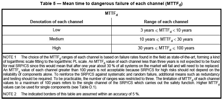
24 MTTF d The time that will elapse until 63% of components fail. Calculated based on B 10d B 10d = Mean cycles until 10% of components fail (should be on the datasheet)
25 Calculation MTTF d = B 10d 0.1 n op B 10d = Cycles to 10% of components fail n op = Mean number of annual operations
26 Calculation MTTF d of all components is calculated and summed using methods in the annexes. PL is determined based on the calculated MTTF d using Tables 5 & 7.
27
28
29 Performance Levels What if you don t have the data to support the required calculations? Means to estimate the required data for different types of components given in the standard. Use the predefined structures given as Category B through 4. ( and 6)
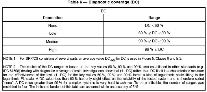
30 Diagnostic Coverage DC describes the ability of the system self-test to detect failures. Table E.1 gives examples
31
32
33
34 Faults Common Mode Failure: A common-mode failure (CMF) is the result of an event(s) which because of dependencies, causes a coincidence of failure states of components in two or more separate channels of a redundancy system, leading to the defined system failing to perform its intended function. Common Cause Failure: "A dependent failure in which two or more component fault states exist simultaneously, or within a short time interval, and are a direct result of a shared cause."
35 Common Cause Failures Annex F provides a scoring system Every part of the safety related part of the control system must be scored More extensive coverage of this topic is in ISO Cascade failures are considered a single fault. Common Cause Faults are considered a single fault
36 Table F.1
37 Common Cause Failures Add up the scores If the CCF score is 65, system is OK If the CCF score is < 65, additional measures required
38 Common Cause Failures Fault exclusion is specifically allowed under 7.3. What does CSA Z say about this? 4.5.5(c): Common mode failures shall be taken into account when the probability of such a failure occurring is significant. Only common MODE failures addressed No guidance on what is considered to be significant
39 Faults and Failures This is the only place where any discussion of Common Mode Failures exists in the CSA standard There is no allowance for fault exclusion in the CSA or the RIA standard. Can you think of specific instances where it would be reasonable to exclude certain failures?


40 Fault Exclusion Would it be reasonable to exclude mechanical failures in a system that used these gate interlocks? If YES, then how do we deal with the no single component failure requirement in 4.5.5? Do we still need two devices on each gate?


41 What about these switches? Fault Exclusion


42 Fault Exclusion What about a switch like this one?
43 Architecture
44 What About Software? Section 4.6 General V & V process Requirements for Safety Related Embedded Software (SRESW) Requirements for Safety Related Application Software (SRASW)
45 Software V & V Section 4.6 Fig. 6 Simplified V-Model Verification
46 Avoiding Software V & V Purchased systems Formal adoption of ISO by the EU has Vendors conduct SRESW resulted in and some SRASW products V coming with a defined PL. &V Some products already have Users provide parameters B 10 or B 10d only figures in their datasheets. Simplifies application development Runs process control code as well (no formal V &V required) Certified systems come with a known Category rating.
47 Wrapping Up Verify that the final PL of the system is greater than or equal to the PL r determined at the beginning of the process. Section 8: Validation process is given in ISO
48 Wrapping Up Aspects not discussed: Section 5: Defining Safety Functions Emergency Stop Safety Related Stop by Safeguard Manual Reset Muting Section 7: Fault Considerations & Exclusions Section 9: Maintenance Section 10: Technical Documentation Section 11: Information for Use
49 Wrapping Up Overall an excellent revision to an important standard Anyone designing safeguarding systems should study this standard and ISO Implementation of ISO mandatory in the EU from 30-Nov-09 ISO has been mandatory since 20- Apr-04. Is influencing coming editions of other machinery standards
50 Other Relevant Standards ISO Safety Of Machinery - Safetyrelated Parts Of Control System - Part 2: Validation ISO Safety Of Machinery - Safety-related Parts Of Control Systems - Part 100: Guidelines For The Use And Application Of ISO
51 Other Relevant Standards IEC Functional Safety Of Electrical/electronic/programmable Electronic Safety Related Systems - Part 1: General Requirements IEC Safety Of Machinery - Functional Safety Of Safety-related Electrical, Electronic And Programmable Electronic Control Systems
52 Thank You! Compliance InSight Consulting Inc. Know Risk Design Safety Kitchener, Ontario, Canada (519) mac.com
PL estimation acc. to EN ISO
 PL estimation acc. to EN ISO 3849- Example calculation for an application MAC Safety / Armin Wenigenrath, January 2007 Select the suitable standard for your application Reminder: The standards and the
Session: 14 SIL or PL? What is the difference?
 Session: 14 SIL or PL? What is the difference? Stewart Robinson MIET MInstMC Consultant Engineer, Pilz Automation Technology UK Ltd. EN ISO 13849-1 and EN 6061 Having two different standards for safety
CT433 - Machine Safety
 Rockwell Automation On The Move May 16-17 2018 Milwaukee, WI CT433 - Machine Safety Performance Level Selection and Design Realization Jon Riemer Solution Architect Safety & Security Functional Safety
Introduction to Machine Safety Standards
 Introduction to Machine Safety Standards Jon Riemer Solution Architect Safety & Security Functional Safety Engineer (TÜV Rheinland) Cyber Security Specialist (TÜV Rheinland) Agenda Understand the big picture
The Best Use of Lockout/Tagout and Control Reliable Circuits
 Session No. 565 The Best Use of Lockout/Tagout and Control Reliable Circuits Introduction L. Tyson Ross, P.E., C.S.P. Principal LJB Inc. Dayton, Ohio Anyone involved in the design, installation, operation,
What safety level can be reached when combining a contactor with a circuitbreaker for fail-safe switching?
 FAQ 01/2015 What safety level can be reached when combining a contactor with a circuitbreaker for fail-safe switching? SIRIUS Safety Integrated http://support.automation.siemens.com/ww/view/en/40349715
Safety Manual VEGAVIB series 60
 Safety Manual VEGAVIB series 60 Contactless electronic switch Document ID: 32002 Contents Contents 1 Functional safety... 3 1.1 General information... 3 1.2 Planning... 4 1.3 Adjustment instructions...
Functional safety. Functional safety of Programmable systems, devices & components: Requirements from global & national standards
 Functional safety Functional safety of Programmable systems, devices & components: Requirements from global & national standards Matthias R. Heinze Vice President Engineering TUV Rheinland of N.A. Email
Safety Manual OPTISWITCH series relay (DPDT)
") Safety Manual OPTISWITCH series 5000 - relay (DPDT) 1 Content Content 1 Functional safety 1.1 In general................................ 3 1.2 Planning................................. 5 1.3 Adjustment
Safety Manual OPTISWITCH series 5000 - relay (DPDT) 1 Content Content 1 Functional safety 1.1 In general................................ 3 1.2 Planning................................. 5 1.3 Adjustment
Safety Manual. Process pressure transmitter IPT-1* 4 20 ma/hart. Process pressure transmitter IPT-1*
 Safety Manual Process pressure transmitter IPT-1* 4 20 ma/hart Process pressure transmitter IPT-1* Contents Contents 1 Functional safety 1.1 General information... 3 1.2 Planning... 4 1.3 Instrument parameter
Safety Manual VEGAVIB series 60
 Safety Manual VEGAVIB series 60 NAMUR Document ID: 32005 Contents Contents 1 Functional safety... 3 1.1 General information... 3 1.2 Planning... 4 1.3 Adjustment instructions... 6 1.4 Setup... 6 1.5 Reaction
Why do I need dual channel safety? Pete Archer - Product Specialist June 2018
 Why do I need dual channel safety? Pete Archer - Product Specialist June 2018 To answer this, we need some basic background information. First why is safety needed? Here are 4 good reasons. 1. To Protect
A study on the relation between safety analysis process and system engineering process of train control system
 A study on the relation between safety analysis process and system engineering process of train control system Abstract - In this paper, the relationship between system engineering lifecycle and safety
Implementing Emergency Stop Systems - Safety Considerations & Regulations A PRACTICAL GUIDE V1.0.0
 Implementing Emergency Stop Systems - Safety Considerations & Regulations A PRACTICAL GUIDE V1.0.0 ~ 2 ~ This document is an informative aid only. The information and examples given are for general use
DeZURIK. KGC Cast Knife Gate Valve. Safety Manual
 KGC Cast Knife Gate Valve Safety Manual Manual D11036 August 29, 2014 Table of Contents 1 Introduction... 3 1.1 Terms... 3 1.2 Abbreviations... 4 1.3 Product Support... 4 1.4 Related Literature... 4 1.5
ICS Supersedes EN ISO :2006. English Version
 EUROPEAN STANDARD NORME EUROPÉENNE EUROPÄISCHE NORM EN ISO 13849-1 June 2008 ICS 13.110 Supersedes EN ISO 13849-1:2006 English Version Safety of machinery - Safety-related parts of control systems - Part
DeZURIK. KSV Knife Gate Valve. Safety Manual
 KSV Knife Gate Valve Safety Manual Manual D11035 August 29, 2014 Table of Contents 1 Introduction... 3 1.1 Terms... 3 1.2 Abbreviations... 4 1.3 Product Support... 4 1.4 Related Literature... 4 1.5 Reference
model for functional safety of
 Application of Weibull reliability model for functional safety of electro-hydraulic system 1 When the safety of the machinery users relies on a reliable function of the control system, than a safety function
DeZURIK Double Block & Bleed (DBB) Knife Gate Valve Safety Manual
 Knife Gate Valve Safety Manual") Double Block & Bleed (DBB) Knife Gate Valve Safety Manual Manual D11044 September, 2015 Table of Contents 1 Introduction... 3 1.1 Terms... 3 1.2 Abbreviations... 4 1.3 Product Support... 4 1.4 Related
Double Block & Bleed (DBB) Knife Gate Valve Safety Manual Manual D11044 September, 2015 Table of Contents 1 Introduction... 3 1.1 Terms... 3 1.2 Abbreviations... 4 1.3 Product Support... 4 1.4 Related
FP15 Interface Valve. SIL Safety Manual. SIL SM.018 Rev 1. Compiled By : G. Elliott, Date: 30/10/2017. Innovative and Reliable Valve & Pump Solutions
 SIL SM.018 Rev 1 FP15 Interface Valve Compiled By : G. Elliott, Date: 30/10/2017 FP15/L1 FP15/H1 Contents Terminology Definitions......3 Acronyms & Abbreviations...4 1. Introduction...5 1.1 Scope.. 5 1.2
Bespoke Hydraulic Manifold Assembly
 SIL SM.0003 1 Bespoke Hydraulic Manifold Assembly Compiled By : G. Elliott, Date: 12/17/2015 Contents Terminology Definitions......3 Acronyms & Abbreviations..4 1. Introduction 5 1.1 Scope 5 1.2 Relevant
Solenoid Valves used in Safety Instrumented Systems
 I&M V9629R1 Solenoid Valves used in Safety Instrumented Systems Operating Manual in accordance with IEC 61508 ASCO Valves Page 1 of 7 Table of Contents 1 Introduction...3 1.1 Terms and Abbreviations...3
Achieving Compliance in Hardware Fault Tolerance
 Mirek Generowicz FS Senior Expert (TÜV Rheinland #183/12) Engineering Manager, I&E Systems Pty Ltd Abstract The functional safety standards ISA S84/IEC 61511 (1 st Edition, 2003) and IEC 61508 both set
Accelerometer mod. TA18-S. SIL Safety Report
 Accelerometer mod. TA18-S SIL Safety Report SIL005/11 rev.1 of 03.02.2011 Page 1 of 7 1. Field of use The transducers are made to monitoring vibrations in systems that must meet particular technical safety
Pneumatic QEV. SIL Safety Manual SIL SM Compiled By : G. Elliott, Date: 8/19/2015. Innovative and Reliable Valve & Pump Solutions
 SIL SM.0010 1 Pneumatic QEV Compiled By : G. Elliott, Date: 8/19/2015 Contents Terminology Definitions......3 Acronyms & Abbreviations..4 1. Introduction 5 1.1 Scope 5 1.2 Relevant Standards 5 1.3 Other
Understanding the How, Why, and What of a Safety Integrity Level (SIL)
") Understanding the How, Why, and What of a Safety Integrity Level (SIL) Audio is provided via internet. Please enable your speaker (in all places) and mute your microphone. Understanding the How, Why, and
Understanding the How, Why, and What of a Safety Integrity Level (SIL) Audio is provided via internet. Please enable your speaker (in all places) and mute your microphone. Understanding the How, Why, and
Managing for Liability Avoidance. (c) Lewis Bass
 Lewis Bass") Managing for Liability Avoidance (c) Lewis Bass 2005 1 Staying Safe in an Automated World Keys to Automation Safety and Liability Avoidance Presented by: Lewis Bass, P.E. Mechanical, Industrial and Safety
Managing for Liability Avoidance (c) Lewis Bass 2005 1 Staying Safe in an Automated World Keys to Automation Safety and Liability Avoidance Presented by: Lewis Bass, P.E. Mechanical, Industrial and Safety
Solenoid Valves For Gas Service FP02G & FP05G
 SIL Safety Manual SM.0002 Rev 02 Solenoid Valves For Gas Service FP02G & FP05G Compiled By : G. Elliott, Date: 31/10/2017 Reviewed By : Peter Kyrycz Date: 31/10/2017 Contents Terminology Definitions......3
Available online at ScienceDirect. Jiří Zahálka*, Jiří Tůma, František Bradáč
 Available online at www.sciencedirect.com Scienceirect Procedia Engineering 69 ( 204 ) 242 250 24th AAAM International Symposium on Intelligent Manufacturing and Automation, 203 etermination and Improvement
SIL explained. Understanding the use of valve actuators in SIL rated safety instrumented systems ACTUATION
 SIL explained Understanding the use of valve actuators in SIL rated safety instrumented systems The requirement for Safety Integrity Level (SIL) equipment can be complicated and confusing. In this document,
SIL Safety Manual. ULTRAMAT 6 Gas Analyzer for the Determination of IR-Absorbing Gases. Supplement to instruction manual ULTRAMAT 6 and OXYMAT 6
 ULTRAMAT 6 Gas Analyzer for the Determination of IR-Absorbing Gases SIL Safety Manual Supplement to instruction manual ULTRAMAT 6 and OXYMAT 6 ULTRAMAT 6F 7MB2111, 7MB2117, 7MB2112, 7MB2118 ULTRAMAT 6E
TEST REPORT Safety Laboratory-MD Team Report No.: RA/2013/90003
 Page: 1 of 16 SHUN HU TECHNOLOGY CO., LTD. No.21, Zhonggong Rd., Xihu Township, Changhua County 514, Taiwan The following merchandise was submitted and identified by the vendor as: Item Information Product
Failure Modes, Effects and Diagnostic Analysis
 Failure Modes, Effects and Diagnostic Analysis Project: Solenoid Drivers KFD2-SL2-(Ex)1.LK.vvcc KFD2-SL2-(Ex)*(.B).vvcc Customer: Pepperl+Fuchs GmbH Mannheim Germany Contract No.: P+F 06/09-23 Report No.:
T71 - ANSI RIA R15.06: Robot and Robot System Safety
 - 5058-CO900H T71 - ANSI RIA R15.06: Robot and Robot System Safety PUBLIC ANSI/RIA R15.06-2012 RIA (print) www.robotics.org + old stds & technical reports ANSI (PDFs): note the TRs are NOT available from
Eutectic Plug Valve. SIL Safety Manual. SIL SM.015 Rev 0. Compiled By : G. Elliott, Date: 19/10/2016. Innovative and Reliable Valve & Pump Solutions
 SIL SM.015 Rev 0 Eutectic Plug Valve Compiled By : G. Elliott, Date: 19/10/2016 Contents Terminology Definitions......3 Acronyms & Abbreviations...4 1. Introduction..5 1.1 Scope 5 1.2 Relevant Standards
TRI LOK SAFETY MANUAL TRI LOK TRIPLE OFFSET BUTTERFLY VALVE. The High Performance Company
 TRI LOK TRI LOK TRIPLE OFFSET BUTTERFLY VALVE SAFETY MANUAL The High Performance Company Table of Contents 1.0 Introduction...1 1.1 Terms and Abbreviations... 1 1.2 Acronyms... 1 1.3 Product Support...
DETERMINATION OF SAFETY REQUIREMENTS FOR SAFETY- RELATED PROTECTION AND CONTROL SYSTEMS - IEC 61508
 DETERMINATION OF SAFETY REQUIREMENTS FOR SAFETY- RELATED PROTECTION AND CONTROL SYSTEMS - IEC 61508 Simon J Brown Technology Division, Health & Safety Executive, Bootle, Merseyside L20 3QZ, UK Crown Copyright
Every things under control High-Integrity Pressure Protection System (HIPPS)
") Every things under control www.adico.co info@adico.co Table Of Contents 1. Introduction... 2 2. Standards... 3 3. HIPPS vs Emergency Shut Down... 4 4. Safety Requirement Specification... 4 5. Device Integrity
Every things under control www.adico.co info@adico.co Table Of Contents 1. Introduction... 2 2. Standards... 3 3. HIPPS vs Emergency Shut Down... 4 4. Safety Requirement Specification... 4 5. Device Integrity
Hydraulic (Subsea) Shuttle Valves
 Shuttle Valves") SIL SM.009 0 Hydraulic (Subsea) Shuttle Valves Compiled By : G. Elliott, Date: 11/3/2014 Contents Terminology Definitions......3 Acronyms & Abbreviations..4 1. Introduction 5 1.1 Scope 5 1.2 Relevant Standards
SIL SM.009 0 Hydraulic (Subsea) Shuttle Valves Compiled By : G. Elliott, Date: 11/3/2014 Contents Terminology Definitions......3 Acronyms & Abbreviations..4 1. Introduction 5 1.1 Scope 5 1.2 Relevant Standards
Section 1: Multiple Choice
 CFSP Process Applications Section 1: Multiple Choice EXAMPLE Candidate Exam Number (No Name): Please write down your name in the above provided space. Only one answer is correct. Please circle only the
Failure Modes, Effects and Diagnostic Analysis
 Failure Modes, Effects and Diagnostic Analysis Project: Temperature transmitter PR5337 / PR6337 / PR7501 with 4..20 ma output Customer: PR electronics A/S Rønde Denmark Contract No.: PR electronics A/S
The following gives a brief overview of the characteristics of the most commonly used devices.
 SAFETY RELATED CONTROL SYSTEMS In a previous article we discussed the issues relating to machine safety systems focusing mainly on the PUWER regulations and risk assessments. In this issue will take this
Failure Modes, Effects and Diagnostic Analysis
 Failure Modes, Effects and Diagnostic Analysis Project: Surge Protective Devices D9324S Customer: G.M. International s.r.l Villasanta Italy Contract No.: GM 16/02-055 Report No.: GM 16/02-055 R005 Version
CENELEC GUIDE 32. Guidelines for Safety Related Risk Assessment and Risk Reduction for Low Voltage Equipment. Edition 1,
 CENELEC GUIDE 32 Guidelines for Safety Related Risk Assessment and Risk Reduction for Low Voltage Equipment Edition 1, 2014-07 CENELEC decided to adopt this new CENELEC Guide 32 through CLC Decision D147/C137.
Rosemount 2130 Level Switch
 Rosemount 2130 Level Switch Functional Safety Manual Manual Supplement Reference Manual Contents Contents 1Section 1: Introduction 1.1 Scope and purpose of the safety manual.............................................
Operating instructions Safety Rope Emergency Stop Switches ZB0052 / ZB0053 ZB0072 / ZB0073
 Operating instructions Safety Rope Emergency Stop Switches UK ZB0052 / ZB0053 ZB0072 / ZB0073 7390878 / 02 03 / 2011 Contents 1 Safety instructions...3 2 Installation / set-up...4 2.1 Applications...4
Reliability of Safety-Critical Systems Chapter 3. Failures and Failure Analysis
 Reliability of Safety-Critical Systems Chapter 3. Failures and Failure Analysis Mary Ann Lundteigen and Marvin Rausand mary.a.lundteigen@ntnu.no RAMS Group Department of Production and Quality Engineering
Section 1: Multiple Choice Explained EXAMPLE
 CFSP Process Applications Section 1: Multiple Choice Explained EXAMPLE Candidate Exam Number (No Name): Please write down your name in the above provided space. Only one answer is correct. Please circle
RESILIENT SEATED BUTTERFLY VALVES FUNCTIONAL SAFETY MANUAL
 Per IEC 61508 and IEC 61511 Standards BRAY.COM Table of Contents 1.0 Introduction.................................................... 1 1.1 Terms and Abbreviations...........................................
DSL, DSH: Specially designed pressure limiter
 Product data sheet 11.1 23.770 DSL, DSH: Specially designed pressure limiter How energy efficiency is improved Control and monitoring according to needs and with no auxiliary energy. Features Switching
SPR - Pneumatic Spool Valve
 SIL SM.008 Rev 7 SPR - Pneumatic Spool Valve Compiled By : G. Elliott, Date: 31/08/17 Contents Terminology Definitions:... 3 Acronyms & Abbreviations:... 4 1.0 Introduction... 5 1.1 Purpose & Scope...
Safety in pneumatic automation
 Safety in pneumatic automation Pharm connect congress 2014 Budapest Feb. 26. 27. Thomas Schulz Head of ISM and KAM Biotech/Pharma Phone: +49-711/347-52192 Mail: thss@de.festo.com Thomas Schulz / CP-KB
E28/Q28 Safety Exhaust Valve Externally Monitored
 E8/Q8 Safety Exhaust Valve Externally Monitored ulletin 9EM4 the total systems approach to air preparation Features Externally Monitored Safety Exhaust Valve Function When applications demand a safe environment
Safety Manual VEGASWING 61, 63. NAMUR With SIL qualification. Document ID: 52084
 Safety Manual VEGASWING 61, 63 NAMUR With SIL qualification Document ID: 52084 Contents Contents 1 Document language 2 Scope 2.1 Instrument version... 4 2.2 Area of application... 4 2.3 SIL conformity...
Safety Circuit Design. Heinz Knackstedt Safety Engineer C&E sales, inc.
 Safety Circuit Design Heinz Knackstedt Safety Engineer C&E sales, inc. 1 OBJECTIVE What are some of the soft issues which determine the final effectiveness of the Functional Safety risk reduction measure
Applications & Tools. Evaluation of the selection of a safetyrelated mode using non-safety-related components
 Cover sheet Evaluation of the selection of a safetyrelated mode using non-safety-related components SINUMERIK 840D sl SINUMERIK Safety Integrated Application description February 2015 Applications & Tools
H250 M9 Supplementary instructions
 H250 M9 Supplementary instructions Variable area flowmeter Safety manual acc. to IEC 61508:2010 KROHNE CONTENTS H250 M9 1 Introduction 3 1.1 Fields of application... 3 1.2 User benefits... 3 1.3 Relevant
Understanding safety life cycles
 Understanding safety life cycles IEC/EN 61508 is the basis for the specification, design, and operation of safety instrumented systems (SIS) Fast Forward: IEC/EN 61508 standards need to be implemented
Table 1: Safety Function (SF) Descriptions
 Descriptions") Table 1: Safety Function (SF) Descriptions NOTE: all safety s are individual safety s TUV NORD? Pressing the Estop PB on the pendant 1 or the Estop (if using the Estop Safety Input configured for Estop)
Table 1: Safety Function (SF) Descriptions NOTE: all safety s are individual safety s TUV NORD? Pressing the Estop PB on the pendant 1 or the Estop (if using the Estop Safety Input configured for Estop)
Transmitter mod. TR-A/V. SIL Safety Report
 Transmitter mod. TR-A/V SIL Safety Report SIL003/09 rev.1 del 09.03.2009 Pagina 1 di 7 1. Employ field The transmitters are dedicated to the vibration monitoring in plants where particular safety requirements
Safety manual for Fisher GX Control Valve and Actuator
 Instruction Manual Supplement GX Valve and Actuator Safety manual for Fisher GX Control Valve and Actuator Purpose This safety manual provides information necessary to design, install, verify and maintain
The IEC61508 Operators' hymn sheet
 The IEC61508 Operators' hymn sheet A few key points for those Operators of plant or equipment that involve SIL rated safety functions*, trips or interlocks by The 61508 Association SAFETY INSTRUMENTED
THE IMPROVEMENT OF SIL CALCULATION METHODOLOGY. Jinhyung Park 1 II. THE SIL CALCULATION METHODOLOGY ON IEC61508 AND SOME ARGUMENT
 THE IMPROVEMENT OF SIL CALCULATION METHODOLOGY Jinhyung Park 1 1 Yokogawa Electric Korea: 21, Seonyu-ro45-gil Yeongdeungpo-gu, Seoul, 07209, Jinhyung.park@kr.yokogawa.com Safety Integrity Level (SIL) is
This manual provides necessary requirements for meeting the IEC or IEC functional safety standards.
 Instruction Manual Supplement Safety manual for Fisher Vee-Ball Series Purpose This safety manual provides information necessary to design, install, verify and maintain a Safety Instrumented Function (SIF)
High Integrity Pressure Protection Systems HIPPS
 High Integrity Pressure Protection Systems HIPPS HIPPS > High Integrity Pressure Protection Systems WHAT IS A HIPPS The High Integrity Pressure Protection Systems (HIPPS) is a mechanical and electrical
Ultima. X Series Gas Monitor
 Ultima X Series Gas Monitor Safety Manual SIL 2 Certified " The Ultima X Series Gas Monitor is qualified as an SIL 2 device under IEC 61508 and must be installed, used, and maintained in accordance with
THE CANDU 9 DISTRffiUTED CONTROL SYSTEM DESIGN PROCESS
 THE CANDU 9 DISTRffiUTED CONTROL SYSTEM DESIGN PROCESS J.E. HARBER, M.K. KATTAN Atomic Energy of Canada Limited 2251 Speakman Drive, Mississauga, Ont., L5K 1B2 CA9900006 and M.J. MACBETH Institute for
Neles trunnion mounted ball valve Series D Rev. 2. Safety Manual
 Neles trunnion mounted ball valve Series D Rev. 2 Safety Manual 10SM D en 1/2017 2 Neles trunnion mounted ball valve, Series D Table of Contents 1 Introduction...3 2 Structure of the D series trunnion
Vibrating Switches SITRANS LVL 200S, LVL 200E. Safety Manual. NAMUR With SIL qualification
 Vibrating Switches SITRANS LVL 200S, LVL 200E NAMUR With SIL qualification Safety Manual Contents 1 Document language 2 Scope 2.1 Instrument version... 4 2.2 Area of application... 4 2.3 SIL conformity...
Safety Legislation and Standards
 Preventa solutions for efficient machine safety Safety Legislation and Standards Catalogue January 2015 How can you fit a 6000-page catalog in your pocket? Schneider Electric provides you with the complete
Failure Modes, Effects and Diagnostic Analysis
 Failure Modes, Effects and Diagnostic Analysis Project: Solenoid Valves SNMF 532 024 ** ** and SMF 52 024 ** ** Customer: ACG Automation Center Germany GmbH & Co. KG Tettnang Germany Contract No.: ACG
WORKSHOP SAFE ENGINEERING
 WORKSHOP Mikaël Degent SICK Product Manager Industrial Machine Expert Stefan Nerinckx SICK Certified Specialist Service Engineer RISK ASSESSMENT EN ISO 12100 Diagnostics before treatment! before! 2018
Failure Modes, Effects, and Diagnostic Analysis of a Safety Device
 Elias Mabook Failure Modes, Effects, and Diagnostic Analysis of a Safety Device Helsinki Metropolia University of Applied Sciences Bachelor of Engineering Degree Programme in Electronics Bachelor s Thesis
Transducer mod. T-NC/8-API. SIL Safety Report
 CEMB S.p.a. Transducer mod. T-NC/8-API SIL Safety Report SIL006/11 rev.0 dated 03.03.2011 Page 1 di 7 1. Employ field The transducers can measure the static or dynamic distance in plants which need to
Failure Modes, Effects and Diagnostic Analysis
 Failure Modes, Effects and Diagnostic Analysis Project: Contact elements Type 8082 and Type 8208 with or without 8602 actuator Customer: R. STAHL Schaltgeräte GmbH Waldenburg Germany Contract No.: Stahl
Failure Modes, Effects and Diagnostic Analysis
 Failure Modes, Effects and Diagnostic Analysis Project: Isolating repeater 9164 Customer: R. STAHL Schaltgeräte GmbH Waldenburg Germany Contract No.: STAHL 16/08-032 Report No.: STAHL 16/08-032 R032 Version
DSB, DSF: Pressure monitors and pressure switches
 roduct data sheet 23.760 DSB, DSF: ressure monitors and pressure switches How energy efficiency is improved Control and monitoring according to needs and with no auxiliary energy Features For regulating
Grantek Systems Integration
 Grantek Systems Integration Understanding Machine Safeguarding and Lockout/Tagout October 18 th 2017 Jeff Winter, CSP, FS Eng. Director, Safety Practice Today s Speaker: Jeff Winter BIO: TUV Certified
Failure Modes, Effects and Diagnostic Analysis. Rosemount Inc. Chanhassen, MN USA
 Failure Modes, Effects and Diagnostic Analysis Project: 3095MV Mass Flow Transmitter Customer: Rosemount Inc. Chanhassen, MN USA Contract No.: Q04/04-09 Report No.: Ros 04/04-09 R001 Version V1, Revision
PROCESS AUTOMATION SIL. Manual Safety Integrity Level. Edition 2005 IEC 61508/61511
 PROCESS AUTOMATION Manual Safety Integrity Level SIL Edition 2005 IEC 61508/61511 With regard to the supply of products, the current issue of the following document is applicable: The General Terms of
Functional Example CD-FE-I-029-V30-EN Safety-related controls SIRIUS Safety Integrated
 Functional Example Safety-related controls SIRIUS Safety Integrated Two safety circuits in a cascade up to SIL 3 acc. to IEC 6206 and PL e acc. to ISO 3849- with ET 200S Safety Motorstarter Solution Local
Failure Modes, Effects and Diagnostic Analysis
 Failure Modes, Effects and Diagnostic Analysis Project: 3051S SIS Pressure Transmitter, with Safety Feature Board, Software Revision 3.0 Customer: Rosemount Inc. Chanhassen, MN USA Contract No.: Ros 02/11-07
Functional Safety SIL Safety Instrumented Systems in the Process Industry
 Products Solutions Services Functional Safety SIL Safety Instrumented Systems in the Process Industry BASF - Press Photo 2 section Foreword rubric 3 Foreword has come into focus since the publication of
DSB, DSF: Pressure monitors and pressure switches
 roduct data sheet 12.1 23.760 DSB, DSF: ressure monitors and pressure switches How energy efficiency is improved Control and monitoring according to needs and with no auxiliary energy. Features For regulating
Safety-critical systems: Basic definitions
 Safety-critical systems: Basic definitions Ákos Horváth Based on István Majzik s slides Dept. of Measurement and Information Systems Budapest University of Technology and Economics Department of Measurement
Design of safety guards Under observation of ISO 14119
 Design of safety guards Under observation of ISO 14119 Introduction With the Machinery Directive (MD) 2006/42 / EC and its associated standards, the European Union has created a set of rules that need
Rosemount 2120 Level Switch
 Rosemount 2120 Level Switch Functional Safety Manual Manual Supplement Manual Supplement Contents Contents 1Section 1: Introduction 1.1 Scope and purpose of the safety manual.............................................
Neles ValvGuard VG9000H Rev 2.0. Safety Manual
 Neles ValvGuard VG9000H Rev 2.0 Safety Manual 10SM VG9000H en 11/2016 2 Neles ValvGuard VG9000H Rev 2.0 Safety Manual Table of Contents 1 General information...3 1.1 Purpose of the document... 3 1.2 Description
Failure Modes, Effects and Diagnostic Analysis
 Failure Modes, Effects and Diagnostic Analysis Project: Digital Output Module Valve DOMV 9478/22-08-51 Company: R. STAHL Schaltgeräte GmbH Waldenburg Germany Contract No.: STAHL 11/01-104 Report No.: STAHL
Application Note. Safety Sub-function PUS Category 1, up to PL c. Application Note PUS, Category 1, up to PL c M20 S22 R20 M1 Q20
 Application Note Safety Sub-function PUS Category 1, up to PL c M20 Application Note PUS, Category 1, up to PL c M1 Q20 M2 S22 R20 G2 100227 Title... Application Note PUS, Category 1, up to PL c Version...
Service & Support. Questions and Answers about the Proof Test Interval. Proof Test According to IEC FAQ August Answers for industry.
 Cover sheet Questions and Answers about the Proof Test Interval Proof Test According to IEC 62061 FAQ August 2012 Service & Support Answers for industry. Contents This entry originates from the Siemens
P33 Safety Exhaust Valve Externally Monitored. Bulletin 0700-B14 ENGINEERING YOUR SUCCESS.
 P Externally Monitored ulletin 07004 ENGINEERING YOUR SUESS. Features Externally Monitored Function When applications demand a safe environment you can count on safety valves from Parker Hannifin. The
Integrating Safety and Automation
 866-522-2300 / www.asesafety.com Integrating Safety and Automation Presented by: Dennis Aulbrook Safeguarding of Automated Machinery A safeguard is a solution or a combination of solutions that eliminate
Application Note. Safety Sub-functions SSC Category 1, up to PL c PUS Category 1, up to PL c. Application Note SSC, PUS, Category 1, up to PL c STOP
 Application Note Safety Sub-functions SSC Category 1, up to PL c PUS Category 1, up to PL c Application Note SSC, PUS, Category 1, up to PL c STOP 100231 Title... Application Note SSC, PUS, Category 1,
Failure Modes, Effects and Diagnostic Analysis
 Failure Modes, Effects and Diagnostic Analysis Project: Ground Monitoring Device 71**/5, 81**/5, 82**/5 Company: R. STAHL Schaltgeräte GmbH Waldenburg Germany Contract No.: STAHL 11/07-089 Report No.:
The Safety Case. Structure of Safety Cases Safety Argument Notation
 The Safety Case Structure of Safety Cases Safety Argument Notation Budapest University of Technology and Economics Department of Measurement and Information Systems The safety case Definition (core): The
IGEM/SR/15 Edition 5 Communication 1746 Integrity of safety-related systems in the gas industry
 Communication 1746 Integrity of safety-related systems in the gas industry Founded 1863 Royal Charter 1929 Patron: Her Majesty the Queen Communication 1746 Integrity of safety-related systems in the gas
Design of safety guards Under observation of ISO 14119
 Design of safety guards Under observation of ISO 14119 Introduction With the Machinery Directive (MD) 2006/42 / EC and its associated standards, the European Union has created a set of rules that needs
Failure Modes, Effects and Diagnostic Analysis
 Failure Modes, Effects and Diagnostic Analysis Project: Variable area flow meter RAMC Customer: Rota Yokogawa GmbH & Co. KG Wehr Germany Contract No.: Rota Yokogawa 05/04-20 Report No.: Rota Yokogawa 05/04-20
Implementing IEC Standards for Safety Instrumented Systems
 Implementing IEC Standards for Safety Instrumented Systems ABHAY THODGE TUV Certificate: PFSE-06-607 INVENSYS OPERATIONS MANAGEMENT What is a Safety Instrumented System (SIS)? An SIS is designed to: respond