PTC Manual. Series 13B
|
|
|
- Blaze Payne
- 6 years ago
- Views:
Transcription


1 PTC Manual Series 13B
2 Electronic Design for Industry 100 Ayers Blvd Belpre, OH (740)
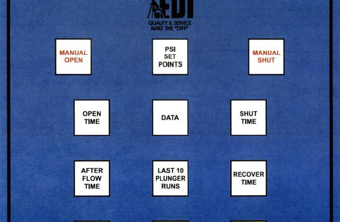
3 DESCRIPTION The EDI Pressure Time Controller (PTC) is a combination of a pressure sensing device and a basic on/off timer. The PTC is a reliable, operator friendly controller, that allows for customization by selecting up to six options. EDI has developed a quality timer combining it with switchgauge functions and delivered it in the PTC. *Note* All characters written in Blue or Red are how the characters will appear on the LCD (Liquid Crystal Display) on the PTC controller. Characters in Blue will appear anytime the associated buttons are pressed. Characters in Red only appear when the appropirate option is turned on and the associated button is pressed. See Controller Options, page #9. FRONT PANEL CONTROLS TIME PERIOD BUTTONS: There are four time period buttons. These buttons allow the operator to display or set time period data. Their designations and functions are as follows: 1. OPEN TIME : Allows the operator to set/read the open time period. 2. SHUT TIME : Allows the operator to set/read the shut time period. 3. AFTER FLOW TIME : Allows the operator to set/read the after flow time period. The After Flow Time follows the Open Time after the plunger reaches surface. The After Flow Time allows additional open time after the plunger has reached surface. 2
4 4. RECOVER TIME : Allows the operator to set/read the recovery time period. The Recover Time follows the Open Time if the plunger fails to reach the surface. The Recover Time is additional shut time to allow for well recovery. Shut Time will follow Recover Time to complete the cycle. When any one of the time period buttons are pressed and held, the Up or Down buttons may be used to alter the time period to any value. If the keypad is unused for one minute, the unit will go to sleep, conserving power. Pressing any button will wake the display. When holding in on the Up and Down buttons, changing time actions will speed up. MANUAL VALVE CONTROL BUTTONS: These buttons allow the operator to manually open and shut the valve. If Option #2 reads Normal Timing, pressing the Manual Open button will also start timing a new open time cycle and pressing the Manual Shut button will start a new shut time cycle. If Option #2 reads Sequential Time, a new open/shut time cycle will be started only if the Up or Down button is simultaneously pressed with the Manual Open/Shut buttons. See Option #2 Page 9. 3
5 LAST 10 PLUNGER RUNS BUTTON: This button allows the operator to display the last 10 plunger travel times. Each time the button is pressed, the next plunger travel time will be displayed. The order they are displayed is as follows: #1(most current) #2 #3 #4 #5 #6 #7 #8 #9 #10, then they repeat the same order. In the following description the characters shown in Blue are what the operator will see on the LCD display; X stands for the actual digits. 1. Plunger travel time #1 (most current). Plunger Travel 1 Xd XXhr XXmn XXs 2. Plunger travel time #2 Plunger Travel 2 Xd XXhr XXmn XXs 3. Plunger travel time #3 Plunger Travel 3 Xd XXhr XXmn XXs Plunger travel times #4 through #10 read same as above. If Plunger Travel Time #1 is viewed during a plunger run, the actual timing in progress may be observed. 4
6 Data Button The Data button allows the operator to scroll through data each time the button is pressed. In the following description, the characters shown in Blue are what the operator will see on the LCD display. The order in which data will be displayed is as follows: 1. Plunger arrival count Plunger Arrivals Plunger failure count Plunger Failures Total Open Time Total Open Time Xd XXhr XXmn 4. Battery Voltage Battery Voltage 0.00V 5. Hi Count Hi Count Lo Count Lo Count 00 To clear the plunger arrival count, plunger failure count, the total open time, hi count and lo count, the operator, while holding this button, can press the Up or Down buttons, and the displayed value will be cleared to zero. NOTE: Total Open Time is displayed in days, hours, and minutes. 5
7 OPERATIONAL DESCRIPTION for EXTERNAL INPUTS EXTERNAL INPUTS OVERRIDE PSI SET POINTS: There are three external inputs available to the operator, Open, Close, and the MSO (magnetic shut off) input. OPEN AND CLOSE INPUTS: These inputs are referred to as the Open inputs and Close inputs. These inputs may be connected between Open, Close, and Common. The inputs are labeled Open, Close, and Common. The Open input, when connected to the Common input, causes an open valve response. The Close input, when connected to the Common input, causes a close valve response. When the Open inputs are closed the valve will open and the Open Time is loaded. The Open Time will start counting when the contacts open. The operator shall be warned of an Open condition. The operator will see Open Time Hold Ext Open For and the time displayed will tell the operator how long the Open contacts have been closed. When the Open contacts open, the time will start counting. When the Close inputs are closed the valve will shut and the Shut Time will be loaded. The Shut Time will start counting when the contacts open. The operator shall be warned of a Close condition. The operator will see Close Time Hold Ext Close Input For and the time displayed will tell the operator how long the Close contacts have closed. When the Close contacts open, the time will start counting. 6
8 PSI Set Points Button The PSI Set Points button allows the operator to view the actual pressure input and scroll through the pnuematic set points. The different set points are as follows: Pressure 0000 (The actual input pressure. This is a read only function.) Hi Pressure Set Point 0000 Lo Pressure Set Point 0000 Valve Delay XXmn XXs Lo Shut In Set Point 00 Hi Shut In Set Point 00 When the actual pressure reaches the Hi Pressure Set Point, the Valve Delaytime starts counting down. When the Valve Delaytime times out the controller will react to the Hi Pressure Set Point, shutting and/or opening the valve. A count will be added to the Hi Count on the Data button. When the actual pressure reaches the Lo Pressure Set Point, the Valve Delaytime starts counting down. When the Valve Delaytime times out the controller will react to the Lo Pressure Set Point, shutting and/or opening the valve. A count will be added to the Lo Count on the Data button. The Valve Delaytime starts counting when a Hi or Lo Pressure Set Point is reached. The controller will not react to the Hior Lo Pressure Set Point until the Valve Delaytime times out. This avoids pressure spikes from shutting and/or opening the valve. The Lo Shut In Set Point counts the number of times the Lo Pressure Set Point is reached. When the Lo Count on the Data button matches the set point, the controller shuts the well in, placing itself in manual mode, until the operator corrects the problem. This set point only appears when Option #4 is turned on. 7
9 The Hi Shut In Set Point counts the number of times the Hi Pressure Set Point is reached. When the Hi Count on the Data button matches the set point, the controller shuts the well in, placing itself in manual mode, until the operator corrects the problem. This set point only appears when Option #4 is turned on. To set a desired value, scroll through the PSI Set Points button. While reading a set point or the valve delay, press the Up or Down button until the desired set point is reached. MAGNETIC SHUT OFF (MSO) INPUT: The MSO inputs are labeled + and. These inputs are designed to connect to the E.D.I. PS4 plunger sensor. Most dry contact inputs will work. 8
10 CONTROLLER OPTIONS: The Control Options button allows the operator to read or set up to six options. To view the current option, press this button. Each time the button is pressed, the next option will be displayed. *Note* All characters in Red and Blue are how the characters will appear on the LCD. Characters in Blue will appear anytime the associated buttons are pressed. Characters in Red only appear when the appropriate option is turned on and the associated button is pressed. Option 1 normal (factory set) IGNORE FALL TIME: Normal timing continues. Option 1 altered USE FALL TIME: Fall Time is available by pushing the Recover Time button twice. Keep the button pressed while setting the desired time. Fall Time overrides external Open inputs, allowing the plunger to reach bottom. Option 2 normal (factory set) NORMAL TIMING: Normal timing continues. Option 2 altered SEQUENTIAL TIMING: The manual shut button, MSO or Close inputs will shut the valve while timing continues through the full cycle. This keeps the controller in sequence with real time, which allows all controllers operating into the same gas line to operate in a set sequence. 9
11 Option 3 normal (factory set) USE PRESSURE: Turns options 4 & 5 on. Allows PSI Set Points to function as set. Option 3 altered IGNORE PRESSURE: Turns options 4 & 5 off. Ignores PSI Set Points. LCD will read: *Option #4 N/A* (N/A = Not Available) Option 4 normal (factory set) IGNORE SHUT IN Normal timing continues. Option 4 altered USE SHUT IN Activates a Lo Shut In Set Point and a Hi Shut In Set Point on the PSI Set Points button. Allows the operator to set a Lo Shut In Set Point. Each time a Lo Pressure Set Point is reached, a count is added to the Lo Count on the Data button. When the Lo Count equals the Lo Shut In Set Point, the well will be shut in and the Hold Close Timer will appear on the LCD and will tell the operator how long the well has been shut in. Allows the operator to set a Hi Shut In Set Point. Each time a Hi Pressure Set Point is reached, a count is added to the Hi Count on the Data button. When the Hi Count equals the Hi Shut In Set Point, the well will be shut in and the Hold Close Timer will appear on the LCD and will tell the operator how long the well has been shut in. Option 5 normal (factory set) HI/LO CLOSE: Turns option 6 on. Allows the Hi Pressure Set Point to open a valve and the Lo Pressure Set Point to close a valve. Option 5 altered HI OPEN/LO CLOSE: Turns option 6 off. Allows both the Hi Pressure Set Point and the Lo Pressure Set Point to close a valve. LCD will read: *Option #6 N/A* (N/A = Not Available) 10
12 Option 6 normal (factory set) CONTINUOUS CYCLE: Normal timing continues. Option 6 altered STOPPED CYCLE: The cycle stops timing after Shut Time, untilhi Pressure Set Point is reached, this will restart the Open Time cycle. The Manual Open button will also restart the Open Time cycle. In the STOPPED CYCLE condition, the LCD will read Hold Close Timer on the LCD and the time displayed will tell the operator how long the well has been shut in (stopped). OPTION TABLE Normal Factory Settings Altered 1 Ignore Fall Time Use Fall Time 2 Normal Timing Sequential Timing 3 Use Pressure Ignore Pressure 4 Ignore Shut In Use Shut In 5 Hi Open/Lo Close Hi/Lo Close 6 Continuous Cycle Stopped Cycle All options are factory set for normal operation. To alter an option, the operator, while holding this button, presses the Up or Down buttons and the option being viewed will be altered. *Note* Option 3 turns on Options 4 and 5. Option 5 turns on Option 6. If Option 4, 5 or 6 are not available, the options will read: *Option #4 N/A* *Option #5 N/A* *Option #6 N/A* 11
13 ELECTRICAL INFORMATION: POWER SUPPLY: (1) 6 volt alkaline lantern battery, Eveready #529 recommended. SOLAR PANEL: The unit may be equipped with a rechargeable 6 volt battery instead of the 6 volt lantern battery. This battery is kept fully charged by a solar panel supplied with this option. POWER CONSUMPTION: Supply voltage Current drain Power 6.5 volts maximum. 120 micro amps average. 780 micro watts average. BATTERY LIFE: The 6 volt battery should last 18 to 36 months, depending on how often the front panel controls are used. The unit shall continue to operate reliably, and shall warn the operator, in the event the battery supply fail. The LCD will read: Low Battery. TEMPERATURE RANGE: The unit is designed to operate reliably from 30 degrees Celsius to +85 degrees Celsius, 22 degrees Fahrenheit to +185 degrees Fahrenheit. Non Metallic Non Corrosive Fiberglass Reinforced Approximately 7 ½ pounds Dimensions: 8x6x4 inches SYSTEM ENCLOSURE: 12
14 NOTES 13
15 NOTES 14
16 Electronic Design for Industry 100 Ayers Blvd Belpre, OH (740)
TSC JR Manual SERIES 2A
 TSC JR Manual SERIES 2A TSC JR Timed Sequence Controller Revised: June 11, 1999 Operation Manual Distributed By: DESCRIPTION The TSC JR is a single valve timer designed to be reliable and operator friendly.
BUBBLER CONTROL SYSTEM
 BUBBLER CONTROL SYSTEM Description: The HDBCS is a fully automatic bubbler system, which does liquid level measurements in water and wastewater applications. It is a dual air compressor system with, air
BUBBLER CONTROL SYSTEM
 BUBBLER CONTROL SYSTEM Description: The LDBCS is a fully automatic bubbler system, which does liquid level measurements in water and wastewater applications. It is a dual air compressor system with, air
Locator Locator-D-Lux Air-Saver G1 Air-Saver G2
 170663_air_saving_products 17-02-2011 16:42 Pagina 1 Locator Locator-D-Lux Air-Saver G1 Air-Saver G2 AIR SAVING PRODUCTS 170663_air_saving_products 17-02-2011 16:42 Pagina 2 170663_air_saving_products
CP3R Quick Start Manual
 RUN MON PRM PU EXT NET RUN D700 3 200V RUN MON PRM PU EXT NET RUN D700 3 200V CP3R Quick Start Manual for Constant Pressure Applications This CP3R Drive has been factory pre-programmed for your specific
CPN1 Quick Start Manual
 RUN MON PRM PU EXT NET RUN RUN MON PRM PU EXT NET RUN CPN1 Quick Start Manual for Constant Pressure Applications This CPN1 Drive has been factory pre-programmed for your specific pressure control application.
DPC-30 DPC-100. Reference Manual
 DPC-30 DPC-100 Reference Manual 1. Introduction 1.1 Description The Martel DPC Digital Pneumatic Calibrator improves upon traditional dial gauge pneumatic calibrators. The Martel DPC improves accuracy,
COMPRESSED AIR SAVING PRODUCTS INDEX. Useful information AIR-SAVER G1 AIR-SAVER G2 LOCATOR. Condensate Management Specialist
 INDEX Useful information AIR-SAVER G1 AIR-SAVER G2 LOCATOR COMPRESSED AIR SAVING PRODUCTS Condensate Management Specialist Information provided herewith is believed to be accurate and reliable. However,
CONTROL LOGIC DESCRIPTION DOCUMENT IC-410ND
 Configuration # : 41G20F0 CONTROL LOGIC DESCRIPTION DOCUMENT IC-410ND Input/output table: Inputs Qty Outputs Qty Inside Temperature Probe 3 Inflatable Balloon 8 Chimney Temperature Probe 1 Chimney Activator
5 Function Indicator. Outside Air Temperature (C) Outside Air Temperature (F) Pressure Altitude Density Altitude Aircraft Voltage STD TEMP SL 15000
 Outside Air Temperature (F) Pressure Altitude Density Altitude Aircraft Voltage STD TEMP SL 15000") 5 Function Indicator +20 +40-5000 STD TEMP SL 15000 Outside Air Temperature (C) Outside Air Temperature (F) Pressure Altitude Density Altitude Aircraft Voltage 427 HILLCREST WAY REDWOOD CITY, CA 94062
5 Function Indicator +20 +40-5000 STD TEMP SL 15000 Outside Air Temperature (C) Outside Air Temperature (F) Pressure Altitude Density Altitude Aircraft Voltage 427 HILLCREST WAY REDWOOD CITY, CA 94062
M104 Series: Digital Manometer: 0.1 % of Full Scale
 M104 Series: Digital Manometer: 0.1 % of Full Scale Copyright 2008 Meriam Content M104 Series: Digital Manometer:...1 0.1 % of Full Scale...1 Content... 2 General information...4 Glossary... 5 General
O P E R A T O R S M A N U A L
 O PERATOR S M ANUAL O PERATOR S M ANUAL PLUNGER LIFT OVERVIEW THEORY OF OPERATION CONTROL MODE SELECTION MECHANICAL INSTALLATION DUAL VALVE OPTION ELECTRICAL INSTALLATION CONNECTOR WIRING SOLAR PANEL WIRE
ACV-10 Automatic Control Valve
 ACV-10 Automatic Control Valve Installation, Operation & Maintenance General: The Archer Instruments ACV-10 is a precision automatic feed rate control valve for use in vacuum systems feeding Chlorine,
UBEC 1AT. AUTO TANK Fill System Installation, Operation, & Setup Instructions
 Document Number: XE-ATA5PM-R1A UBEC 1AT AUTO TANK Fill System 08899155 Installation, Operation, & Setup Instructions Rev170906-EB-FRC PHYSICAL: 1302 WEST BEARDSLEY AVE ELKHART, IN 46514 WWW.ELKHARTBRASS.COM
Table of Contents. Important Safety Information...1. Getting Started...1. Getting Started: Commands...3. Installation Instructions...
 Table of Contents Important Safety Information...1 Getting Started...1 Getting Started: Commands...3 Installation Instructions...4 Operating Features...9 Maintenance Checklist...22 Troubleshooting/FAQ
Aquacom Diving Equipment
 Aquacom Diving Equipment Tough, powerful and a must for professional search and rescue teams, the Aquacom system ensures clear communication between underwater divers and surface control. D-27802-2009
unconventional-airsoft.com
 unconventional-airsoft.com Congratulations on your new digital fire control computer! This unit will change the way you use and look at your electric gun. With this short document, you will know all you
SCF Softball Club Scoreboard Controller Operation
 SCF Softball Club Scoreboard Controller Operation A PowerPoint presentation for operating the Scoreboard Controller during Sun City Festival Senior Softball Games September 2014 (Press mouse key to advance
KELCO F60 DIGITAL PUMP CONTROLLER
 KELCO F60 DIGITAL PUMP CONTROLLER PROGRAMMING INSTRUCTIONS KELCO Engineering Pty Ltd Sydney Australia www.kelco.com.au Table Of Contents Introduction 1 Programming the Controller 2 F60 Modes and Functions,
OMNISPORT 2000 SWIMMING QUICK REFERENCE
 Before During After OMNISPORT 2000 SWIMMING QUICK REFERENCE 1. Confirm that the timer is reset. 2. Set the timer to the correct event and heat. The right LCD, line 2 displays E:(event) H:(heat) R:(round)
SPECIFICATIONS APCEPH1
 APCEPH1 ph CONTROLLER SPECIFICATIONS APCEPH1 Input voltage 120 Volts AC Maximum amperage 14.5 amps @ 120 VAC ph Accuracy +/- 0.2 ph ph Control range Adjustable 4.5 8.5 ph Weight < 1 lbs Dimensions 3" x
GasSense NDIR User Manual
 INDEX INDEX... 1 1. OVERVIEW... 2 2. TECHNICAL DATA... 3 3. SPECIFICATIONS... 4 4. PRODUCT DESCRIPTION... 5 4.1 Mechanical details... 5 4.2 Piping... 7 4.3 Connections... 7 5. INSTALLATION... 10 6. CALIBRATION
Altimeter and Compass Watch Instruction Manual
 Altimeter and Compass Watch Instruction Manual Overview Figure 1 LCD display description Features Hour, minute, second, year, Auto calendar 12/24 hour format display month, day, day of week Daily alarm
TEL/jlRE" Introduction. Display Features and Modes. Startup Procedure. Power-Up Procedure. Adjustment Modes
 TEL/jlRE" Introduction The Telaire 7001 CO 2 /T emperature monitor (shown in Fi gt u e 1 below) is an easy to use hand-held instnunent, which provides stable and highly accurate readings due to Telaire
A I R S W I N G E R O P E R A T O R S M A N U A L
 A I R S W I N G E R O P E R A T O R S M A N U A L Safety Instructions When using your heat press, basic precautions should always be followed, including the following:. 2. 3.. 5. 6. 7. 8. 9. 0.. Read all
Touch Screen Guide. OG-1500 and OG Part # T011
 Touch Screen Guide OG-1500 and OG-2000 Part # 9000000.T011 Effective 11/2010 External View Internal View 1. Transducer Banks 2. Oxygen Sensor 3. PLC These are the two manifolds with three (3) transducers
Pneumator. Testo Industrial Services More assurance, better service. Pressure calibrator and measuring instrument.
 Pressure calibrator and measuring instrument Testo Industrial Services More assurance, better service. www.testotis.com Full versatility for industrial requirements In industrial practice, the precision
Owners Manual Models: 075-AQF-CX. Aquatrol Backwashing Catalytic Carbon Filter. Visit us online at.
 Visit us online at www.uswatersystems.com Aquatrol Backwashing Catalytic Carbon Filter Owners Manual Models: 075-AQF-CX REVISION # 1.0 REVISION DATE October 11, 2017 US Water Systems, Inc. 1209 Country
Operating Instructions Part No
 DIGITAL AUTOMATIC TYRE INFLATOR Operating Instructions Part No. 11.0578 Thank you for selecting this Jamec Pem Automatic Tyre Inflator. Please read this manual before carrying out any installation or service
DIGITAL AUTOMATIC TYRE INFLATOR
 DIGITAL AUTOMATIC TYRE INFLATOR Instruction Manual PSI Part No. 11.0556 Digital Automatic Tyre Inflator (Portable) Thank you for selecting our Digital Automatic Tyre Inflator (Portable), please read this
In Response to a Planned Power Outage: PPMS EverCool II Shut Down and Re-start Procedure
 PPMS Service Note 1099-412 In Response to a Planned Power Outage: PPMS EverCool II Shut Down and Re-start Procedure Introduction: Loss of electricity to the PPMS EverCool II should not cause damage to
AA GWR Water Retention Meter for Accurate Measurement of Water Retention
 AA GWR Water Retention Meter for Accurate Measurement of Water Retention Principle of Measurement: Coating color is poured into a test cell and separated from a blotting paper with a filter. The cell is
MP15 Jockey Pump Controller
 Setup and Operating Instructions MP15 Jockey Pump Controller This manual provides general information, installation, operation, maintenance, and system setup information for Metron Model MP15 Jockey Pump
CONSOLE-320 ENGLISH. 230A: CONSOLE-320 with cable data output Item 230B: CONSOLE-320 with cable + wireless radio data output
 CONSOLE-320 Item 230A: CONSOLE-320 with cable data output Item 230B: CONSOLE-320 with cable + wireless radio data output Table of contents 1. INTRODUCTION...2 1.1 Power supply...2 1.2 Connections...2 1.3
INSTALLATION. and INSTRUCTION MANUAL. for QUALITY AIR BREATHING SYSTEMS. Model 50-P-Mini Portable Systems Outfitted with ABM-725 Monitor
 INSTALLATION and INSTRUCTION MANUAL for QUALITY AIR BREATHING SYSTEMS Model 50-P-Mini Portable Systems Outfitted with ABM-725 Monitor M A R T E C H S E R V I C E S C O M P A N Y P.O. Box 7079 OFFICE: (507)
TABLE OF CONTENTS INTRODUCTION 3 SAFETY PRECAUTIONS 3 PACKAGE CONTENTS 4 DEVICE OVERVIEW 4 BUTTON OPERATION SUMMARY 5 BASIC OPERATION 6
 TABLE OF CONTENTS INTRODUCTION 3 SAFETY PRECAUTIONS 3 PACKAGE CONTENTS 4 DEVICE OVERVIEW 4 BUTTON OPERATION SUMMARY 5 BASIC OPERATION 6 CURRENT TIME MODE 7 FUNCTIONAL DISPLAY 7 WEATHER FORECAST FEATURE
Nothing's as cool, as a freshwater pool. easychem 770 ORP and ph Controller for Pools and Spas with Timer Output for Pool Pump
 Page 1 of 6 TPS Australia - Quality hand-made instruments since 1968. Nothing's as cool, as a freshwater pool easychem 770 ORP and ph Controller for Pools and Spas with Timer Output for Pool Pump Automatic
MICRO BASED CONTROL SYSTEM YLCS-SA/HA/AA YAES-SA 2 System YAES-SA 3 System YAES-DSA 4 System
 MICRO BASED CONTROL SYSTEM YLCS-SA/HA/AA YAES-SA 2 System YAES-SA 3 System YAES-DSA 4 System OPERATION INSTRUCTION YLCS-SA/HA/AA: R134a - Software Version B.A05.01.01 and higher version levels YAES-SA
OC Panel High Limit Aquastat Kit, Manual Reset p/n
 OC Panel High Limit Aquastat Kit, Manual Reset p/n 233202 Instruction Sheet APPLICATION The OC (Option Control) Panel High Limit Aquastat Kit provides electronic temperature sensing in a UL limit-rated
RAM 4021-DPX Operation Manual
 RAM 4021-DPX Operation Manual Worldwide Manufacturer of Gas Detection Solutions TABLE OF CONTENTS ABL 4021-DPX / RAM 4021-DPX For Your Safety... 3 Description... 3 Setup Mode... 4 Lights/Alarms... 4 Operation...
KEG PUMP. Range of Electric Keg Pumps
 KP KEG PUMP Range of Electric Keg Pumps Electric Keg (Drum) Pumps for Grease KEG PUMP Versatile range of Interlube electric grease pumps for industrial and off-road applications The KP keg pump is available
PART 5 - OPTIONS CONTENTS 5.1 SYSTEM EXPANSION 5-3
 PART 5 - OPTIONS CONTENTS Para Page 5.1 SYSTEM EXPANSION 5-3 5.2 SENSORS 5-3 5.2.1 Trim Angle Sensor 5-3 5.2.2 Mast Rotation Sensor 5-3 5.2.3 Heel Angle Sensor 5-3 5.2.4 Barometric Pressure Sensor 5-3
AIR SAVING PRODUCTS ADDING VALUE AIR-SAVER LOCATOR LOCATOR-EV
 AIR SAVING PRODUCTS AIR-SAVER LOCATOR LOCATOR-EV ADDING VALUE REL LIABLE COMPRESSED AIR CONDENSATE MANAGEMENT AND ENERGY SAVING PRODUCTS Air saving products INDEX Chapter Content 1 Introduction to compressed
AFDXXX(X)AC Series Operators Manual Please read this manual thoroughly before attempting to operate your water maker.
AC Series Operators Manual Please read this manual thoroughly before attempting to operate your water maker.") AFDXXX(X)AC Series Operators Manual Please read this manual thoroughly before attempting to operate your water maker. E & O E Danger High Voltage AFDXXX(X) Series water makers operate on a 240vAC electricity
AFDXXX(X)AC Series Operators Manual Please read this manual thoroughly before attempting to operate your water maker. E & O E Danger High Voltage AFDXXX(X) Series water makers operate on a 240vAC electricity
Manual Weighingblock VB2 series and Uniscale
 Manual Weighingblock VB2 series and Uniscale Note: At page 8 in this manual you will find a short form instruction. Normally the only instruction shipped together with the Scale. Overview different ranges.
Vers Gas Generator. Release III INSTRUCTION MANUAL. Advanced Calibration Designs, Inc.
 Advanced Calibration Designs, Inc. Vers ersacal Gas Generator Release III Advanced Calibration Designs, Inc. 2024 W. McMillan Street Tucson, Arizona 85705 U.S.A. Telephone: (520) 290-2855 Fax: (520) 290-2860
SIP 1000 OPERATION AND PROGRAMMING MANUAL
 SIP 1000 OPERATION AND PROGRAMMING MANUAL 1 Below, please find an illustration that will show you the major functions and components of the SIP 1000: Before the Programming is explained, on the next page
GAS FUEL VALVE FORM AGV5 OM 8-03
 ALTRONIC AGV5 OPERATING MANUAL GAS FUEL VALVE FORM AGV5 OM 8-03 WARNING: DEVIATION FROM THESE INSTALLATION INSTRUCTIONS MAY LEAD TO IMPROPER ENGINE OPERATION WHICH COULD CAUSE PERSONAL INJURY TO OPERATORS
MODEL NUMBER: P-A AUTOMATIC PORTABLE COMPRESSOR
 MODEL NUMBER: 45043-450P-A AUTOMATIC PORTABLE COMPRESSOR IMPORTANT: It is essential that you and any other operator of the product read and understand the contents of this manual before installing and
Standard Chiller 1/4 compressors Manual version: /10/96
 Application program for Macroplus II Standard Chiller 1/4 compressors Manual version: 1.4-18/10/96 Program code: EP000ECH02 Rif.: 68EM Contents 0$,1)($785(6 HARDWARE...2 FUNCTIONS OF THE SYSTEM...3 PROTECTIONS...3
Stand-Alone Bubble Detection System
 Instruction Sheet P/N Stand-Alone Bubble Detection System 1. Introduction The Bubble Detection system is designed to detect air-bubble induced gaps in a bead of material as it is being dispensed. When
DT 630 ALTIMETER, BAROMETER AND COMPASS WATCH OPERATING INSTRUSTIONS
 DT 630 ALTIMETER, BAROMETER AND COMPASS WATCH OPERATING INSTRUSTIONS Overview:--- Positive or Negative Icon Barometric Trend Indicator SELECT Low Battery Indicator AM/FM Indicator Daily Alarm Indicator
VARIOspeed 3R User Manual
 VARIOspeed 3R User Manual This VARIOspeed 3R control panel is designed to provide constant pressure control for your pumping system. Should you need to make minor adjustments, please consult the parameter
istart Owner s Manual
 istart Owner s Manual istart Whistle istart Pro istart Controller Introduction The istart Whistle, istart Pro and istart Controller are self-contained automatic sailboat race starters using the latest
ELIMINATOR INSTRUCTIONS Table of Contents
 ELIMINATOR INSTRUCTIONS Table of Contents 1. PRACTICE MODE A. Toggling from Full to Pro Tree B. Toggling from 1 to 2 Users C. Toggling from Auto to Manual Reset D. Setting the Delay Boxes E. Setting a
CCT-7320/ROC-2313 Reverse Osmosis Controller
 CCT-7320/ROC-2313 Reverse Osmosis Controller 1 General The instrument is a combined control instrument of a reverse osmosis controller and an on-line conductivity instrument. It can perform the operation
Ocean Observatories Initiative. Coastal & Global Scale Nodes. Hydrogen Safety. OOI Surface Mooring Hydrogen Safety Review
 Ocean Observatories Initiative Coastal & Global Scale Nodes Hydrogen Safety CP01 Mooring Timeline: 21 November 2013: CP01CNSM was deployed and transitioned to shore controlled operations. 17 Feb. 2014:
AIR-SAVER G1 AIR-SAVER G2 LOCATOR-EV COMPRESSED AIR CONDENSATE MANAGEMENT AND ENERGY SAVING PRODUCTS AIR SAVING PRODUCTS
 AIR-SAVER G1 AIR-SAVER G2 LOCATOR-EV ENVIRONMENT ADDING VALUE SAFEGUARD RELIABLE COMPRESSED AIR CONDENSATE MANAGEMENT AND ENERGY SAVING PRODUCTS AIR SAVING PRODUCTS Air saving products INDEX Chapter Content
HEAT-TIMER CORP. 20 NEW DUTCH LANE FAIRFIELD, NEW JERSEY TEL. (973) FAX (973) INSTALLATION & OPERATION MANUAL TABLE OF CONTENTS
 FAX (973) INSTALLATION & OPERATION MANUAL TABLE OF CONTENTS") HEAT-TIMER CORP. 20 NEW DUTCH LANE FAIRFIELD, NEW JERSEY 07004 TEL. (973)575-4004 FAX (973)575-4052 INSTALLATION & OPERATION MANUAL MODEL MOD-4 TABLE OF CONTENTS Control Panel...2 MOD-4 Overview...4 Installation...6
HEAT-TIMER CORP. 20 NEW DUTCH LANE FAIRFIELD, NEW JERSEY 07004 TEL. (973)575-4004 FAX (973)575-4052 INSTALLATION & OPERATION MANUAL MODEL MOD-4 TABLE OF CONTENTS Control Panel...2 MOD-4 Overview...4 Installation...6
WATER CONTROL SYSTEM QUICK START
 SETTINGS MENU SYSTEM OPTIONS WATER LEVEL BAR GRAPH 3 DS SPRAY ON/OFF CS SPRAY ON/OFF BEACON WATER CONTROL SYSTEM QUICK START WWW.GFWORLDWIDE.COM +1 (208) 664-9291 SERVICE@GFWORLDWIDE.COM DISPLAY SCREEN
Series 180. Commercial/Industrial Control System Installation, Operation and Maintenance Manual
 Series 180 Commercial/Industrial Control System Installation, Operation and Maintenance Manual Table of Contents Installation............................ 3 Plumbing Inlet and Outlet Piping Drain Line Piping
INSTRUCTION MANUAL. Automatic Water Softener System. Model: PSE-08. Xsential Water Filtration Systems
 INSTRUCTION MANUAL Automatic Water Softener System Model: PSE-08 Xsential Water Filtration Systems 78 Daly Street Ascot Western Australia 6104 Ph: 1300 366 295 Fax: (08) 9277 2266 www.xsential.com.au Welcome
MODEL 9875 STADIUM BASEBALL SCOREBOARD. Instruction Manual
 UNITEC MANUFACTURING DIVISION MODEL 9875 STADIUM BASEBALL SCOREBOARD (WITH INNING BY INNING SCORING) Instruction Manual Mailing Address: PO Box 260, Yorkville, NY 13495-0260 Plant Address: 34 Main Street,
BAPI Pressure Line of Products - FAQs
 Table of Contents 1. Several manufacturers produce pressure transmitters, why should I purchase from BAPI?... p. 2 2. BAPI makes several styles of pressure transmitters. What are the features of each?...
TANK MANAGER FOR TWO TANKS OPERATING MANUAL. 10/31/11 C-More T6C L color touch panel
 TANK MANAGER FOR TWO TANKS OPERATING MANUAL 10/31/11 C-More T6C L color touch panel 1 TABLE OF CONTENTS GENERAL...3 INSTALLATION...4 STONE TEST PROCEDURE...7 OPERATIONAL SUMMARY...7 AUTO CARBONATION...10
Using the UltraRAE. Firmware 2.35
 Using the UltraRAE Firmware 2.35 Training Agenda UltraRAE features Setting up the UltraRAE Turning on the UltraRAE Idle Operation RAE-Sep Tubes Prepping for a measurement Taking a measurement Alarm modes
AUTOMATIC TIRE INFLATOR # MW-60, MW-60-4WAY & MW-64HP
 USER MANUEL AUTOMATIC TIRE INFLATOR # MW-60, MW-60-4WAY & MW-64HP TIRE EQUIPMENT MANUFACTURER 1.866.409.RACK WWW.MARTINSINDUSTRIES.COM info@martinsindustries.com PARTS Verify that the following components
NITROGEN INFLATION SYSTEM NG-4, NG-6, NG-12, NG-18
 NITROGEN OPERATING INSTRUCTIONS NITROGEN INFLATION SYSTEM NG-4, NG-6, NG-12, NG-18 READ INSTRUCTIONS THOROUGHLY BEFORE OPERATING 3451 S. 40th Street Phoenix, AZ 85040 602.437.5020 800.223.4540 www.tsissg.com
LENNOX SLP98UHV DIAGNOSTIC CODES
 Code Status of Equipment Action required to clear and recover - Idle mode (Decimal blinks at 1 Hertz -- 0.5 second ON, 0.5 second OFF) A Cubic feet per minute (cfm) setting for indoor blower (1 second
HS Bubbler Technology. HyQuest Solutions New Zealand User Group August 2017
 HS Bubbler Technology HyQuest Solutions New Zealand User Group August 2017 Origins of Gas Purge Technology 1940 s - Developed By Dutch Engineer Late 1940 s 1954 - Adopted by State of Illinois Water Group
DRS4-RM Manual. Set Up Instructions for DRS4 Series Single Tank
 Set Up Instructions for DRS4 Series Single Tank Inspect the packaging of the equipment to confirm that nothing was damaged during shipping. (Figure 1) Remove the resin tank(s) and valve(s) from the packaging.
450P AUTOMATIC PORTABLE COMPRESSOR EXTREME SERIES
 EXTREME SERIES PART NO. 45043 IMPORTANT: It is essential that you and any other operator of this product read and understand the contents of this manual before installing and using this product. SAVE THIS
Chemical Feed Equipment Floor-Mounted Gas Dispenser - Series CH4200
 Specification Bulletin (rev.01) Series CH4200 Chemical Feed Equipment Floor-Mounted Gas Dispenser - Series CH4200 Easy, fast& accurate digital with 11 points calibration Laser sensor offering actual feed
Performa Cv Twin Alternating and High Flow Systems. Manual Supplement
 Performa Cv Twin Alternating and High Flow Systems Manual Supplement Table of Contents 1.0 Installation and Start-Up.............. 3 Water Line Connection Brine Tank Turbine Connection Connecting Manifold
User Manual GRI- 1500Li
 User Manual GRI- 1500Li Your Cart Tek caddy cart was thoroughly quality control checked and road tested before being shipped to your address. We do everything possible to assure that your caddy is in perfect
CONDUCTIVITY POINT/S LEVEL SWITCH JAYCEEAQUA 4000 SERIES
 I N S T R U C T I O N - M A N U A L CONDUCTIVITY POINT/S LEVEL SWITCH JAYCEEAQUA 4000 SERIES FUNCTION: Conductivity level limit switches are based on the principle of measuring level through the electrical
User Manual. asense VAV. CO 2 / temperature sensor with built-in general purpose controller
 Gas and Air Sensors User Manual asense VAV CO / temperature sensor with built-in general purpose controller General The IAQ-sensor product asense VAV is used to measure indoor air carbon dioxide concentration
The Univentor 1250 Anaesthesia Unit
 THE UNIVENTOR 1200/1250 ANAESTHESIA UNIT The Univentor 1250 Anaesthesia Unit TABLE OF CONTENTS EDITION 1 Section 1 - WARRANTY & SERVICE 1.1. WARRANTY 2 1.2. DAMAGED SHIPMENTS 2 1.3. SERVICE 2 Section 2
D OPERATION and MAINTENANCE MANUAL MILITARY ALTIMASTER MA-10 (30,000 foot COMPRESSED SCALE: FP-02093) January 3, 2008 REV 12
 January 3, 2008 REV 12") D-90046 OPERATION and MAINTENANCE MANUAL MILITARY ALTIMASTER MA-10 (30,000 foot COMPRESSED SCALE: FP-02093) January 3, 2008 REV 12 D-90046 Manual, Operation and Maintenance MA-10 Compressed Rev 12.doc
D-90046 OPERATION and MAINTENANCE MANUAL MILITARY ALTIMASTER MA-10 (30,000 foot COMPRESSED SCALE: FP-02093) January 3, 2008 REV 12 D-90046 Manual, Operation and Maintenance MA-10 Compressed Rev 12.doc
Ocean Technology Systems ComBox
 Undersea Systems International, Inc. dba Ocean Technology Systems ComBox Silver Bullet User s Guide Technology in Depth - NOTICE - This manual and the information contained herein are provided for use
Operating instructions Electrical switching facility pco
 Operating instructions Electrical switching facility pco from software version V1.33 on TABLE OF CONTENTS 1. Before you start... 4 1.1 Brief description... 4 1.2 Using this manual... 4 2. pco integrated
StockWeigh 500 D3632 US-B
 OPERATORS MANUAL DIGI-STAR 790 WEST ROCKWELL AVENUE FORT ATKINSON, WISCONSIN 53538 PHONE: (920) 563-1400 TECHNICAL SERVICE: 1-800-225-7695 (920) 563-9700 D3632 US- Rev. B August 4, 2004 StockWeigh 500
SRL Series. Oil-less Scroll Air Compressors. Pharmaceutical. Research & Development. Food & Beverage. Chemical. Electronic
 Pharmaceutical SRL Series Oil-less Scroll Air Compressors Research & Development Food & Beverage Chemical Electronic Hitachi Industrial Equipment Product Brochure Hitachi SRL Series scroll compressors
MicroTim XB. User Manual. Precision Digital Barometric Altimeter / Barometer / VSI. Document Revision 1.0 Firmware Version 3.0
 MicroTim XB Precision Digital Barometric Altimeter / Barometer / VSI User Manual Document Revision 1.0 Firmware Version 3.0 Table of Contents Table of Contents...2 1 General Operation...5 1.1 Altitude
RAM Operation Manual. Worldwide Manufacturer of Gas Detection Solutions
 RAM 4021 Operation Manual Worldwide Manufacturer of Gas Detection Solutions TABLE OF CONTENTS RAM 4021 For Your Safety... 2 Description.... 2 Setup Mode.... 2 Lights/Alarms.... 3 Operation.... 4 Calibration....
Reverse Osmosis System Installation Guide and Operation Manual.
 Reverse Osmosis System Installation Guide and Operation Manual. Table of Contents 1 Introduction...2 2 Installation...3 2.1 Feed water connection...3 2.2 Permeate and concentrate plumbing...3 2.3 Electrical
Technical Bulletin 112 Developed with Industry
 Technical Bulletin 112 Developed with Industry Title: Obtaining meter index readings for gas rating on electronic and SMART gas meters Date issued: 7 December 2017 Note: This version of Technical Bulletin
UNIVERSITY OF ROCHESTER ENVIRONMENTAL HEALTH & SAFETY
 Revision No.: 1 Page 1 of 6 I. PURPOSE This policy/procedure establishes the proper steps for set up, and operation of the BullEx I.T.S Xtreme training system. II. PERSONNEL AFFECTED Fire Safety staff
INSTALLATION. and INSTRUCTION MANUAL. for QUALITY AIR BREATHING SYSTEMS. Model 50 Systems Outfitted with ABM-725 Monitor C O M P A N Y
 INSTALLATION and INSTRUCTION MANUAL for QUALITY AIR BREATHING SYSTEMS Model 50 Systems Outfitted with ABM-725 Monitor M A R T E C H S E R V I C E S C O M P A N Y OFFICE: (507) 843-4700 P.O. BOX 7079 Toll
RAM 4021-PR. Operation Manual. Worldwide Manufacturer of Gas Detection Solutions
 RAM 4021-PR Operation Manual Worldwide Manufacturer of Gas Detection Solutions TABLE OF CONTENTS RAM 4021-PR For Your Safety... 2 Description.... 2 Setup Mode.... 2 Lights/Alarms.... 3 Operation.... 4
Temperature Controller CC24-7 ULTRA USER S MANUAL Legion Dr. Mason, MI USA October 2010 Ph. (517) Fax (517)
 Fax (517)") Temperature Controller USER S MANUAL Aerotech, Inc. FORM: QM1387 4215 Legion Dr. Mason, MI 48854-1036 USA October 2010 Ph. (517) 676-7070 Fax (517) 676-7078 FOR CUSTOMER USE Enter the serial number located
Temperature Controller USER S MANUAL Aerotech, Inc. FORM: QM1387 4215 Legion Dr. Mason, MI 48854-1036 USA October 2010 Ph. (517) 676-7070 Fax (517) 676-7078 FOR CUSTOMER USE Enter the serial number located
MOYNO FLUID DETECTION CONTROL SERVICE MANUAL. Section: ACCESSORIES. Page: 1 of 8 Date: May 1, 1998 GENERAL
 MOYNO Section: ACCESSORIES Page: 1 of 8 Date: May 1, 1998 SERVICE MANUAL FLUID DETECTION CONTROL GENERAL The Moyno Fluid Detection Control prevents unnecessary loss of production time or repair costs to
Iron Filter Installation / Operation Manual
 Iron Filter Installation / Operation Manual BrassMaster and BrassMaster Plus Technical Video Library: http://watercontrolinc.com/residential-technical-support/residential-technical-videos BrassMaster technical
Sampling Equipment Catalog. MicroPurge Low-Flow Pump Control
 MicroPurge Low-Flow Pump Control Sampling Equipment Catalog 10 MicroPurge Controls The MicroPurge Controller (U.S. Patent Number 6,508,310) revolutionizes low-flow sampling with advanced logic control
Qi Litre Ultrasonic Cleaner
 Qi-300 17Litre Ultrasonic Cleaner Ultrawave s Qi-Series are robust and reliable, delivering outstanding cleaning performance in a wide range of industries. From precision, pharmaceutical and medical device
Autotrol Performa ProSoft
 Autotrol Performa ProSoft With 960 Series Control 5-Cycle Conditioner 5-Cycle FA Filter Water Conditioning Control System Installation, Operation and Maintenance Manual Table of Contents Installation.....................................
MONSOON 6V Pump Control System
 MONSOON 6V Pump Control System Installation and Operating Instructions Please pass these instructions on to the operator of this equipment. INTRODUCTION MONSOON 6V Pump Controller The MONSOON 6V pump control
User s Guide. Vacuum Controller for liquid delivery systems
 Flow Control User s Guide Vacuum Controller for liquid delivery systems Precise Vacuum Control throughout the experiment Flow control Compatible with any perfusion system Ideal for Small Volume Delivery
DRILL MONITOR DM-100 OPERATIONS MANUAL
 DRILL MONITOR DM-100 OPERATIONS MANUAL 1 INSTALLATION AND SETUP The Drill Monitor comes complete with the following parts: 1 Drill Monitor unit 1 Mounting bracket for Drill Monitor 1 Encoder 1 Encoder
CPF 270, CPF 340. Instruction book
 CPF 270, CPF 340 Instruction book Chicago Pneumatic CPF 270, CPF 340 Instruction book Original instructions Copyright Notice Any unauthorized use or copying of the contents or any part thereof is prohibited.