Change all references to Material Safety Data Sheets (MSDS) to Safety Data Sheets (SDS).
|
|
|
- Jemimah McBride
- 6 years ago
- Views:
Transcription
1 National Fire Protection Association Report of /9/ :04 AM Second Revision No. 23-NFPA [ Global Comment ] Change all references to Material Safety Data Sheets (MSDS) to Safety Data Sheets (SDS). Submitter Information Verification Submitter Full Name: [ Not Specified ] Organization: [ Not Specified ] Street Address: City: State: Zip: Submittal Date: Mon Jul 14 10:40:31 MDT 2014 Committee Statement Committee Statement: Response Message: This is an editorial change to align the terminology of NFPA 55 with that of the Global Harmonized System adopted by OSHA in 2012
2 National Fire Protection Association Report of /9/ :04 AM Second Revision No. 64-NFPA [ Global Comment ] In Annex H, change all occurrences of Tables (a) through (c) and Tables (a) and (b) to Tables (a) through (c), respectively. Submitter Information Verification Submitter Full Name: Sonia Barbosa Organization: [ Not Specified ] Street Address: City: State: Zip: Submittal Date: Fri Sep 05 12:23:35 EDT 2014 Committee Statement Committee Statement: Response Message: Response to PC-35. Note that the submitted attached a word file to the document, the SR just makes the changes in Terra. This updates the table numbers in Annex H to match the reorganizations of Chapters 7 and 10.
3 National Fire Protection Association Report of /9/ :04 AM Second Revision No. 65-NFPA [ Global Comment ] Reorganize Chapters 7 and 10 according to the attached spreadsheet and/or word files. Supplemental Information File Name NFPA_55_Chapter_7_and_10_Reorganization..xlsx 55-Chapter_7-SR-clean.docx 55-Chapter_10-SR-clean.docx Description Spreadsheet with reorganization Submitter Information Verification Submitter Full Name: Sonia Barbosa Organization: [ Not Specified ] Street Address: City: State: Zip: Submittal Date: Thu Oct 02 14:22:34 EDT 2014 Committee Statement Committee Statement: The committee is reorganizing the material currently in Chapters 7 and 10 of the document to locate all of the hydrogen content in Chapter 10. The material in Chapter 10 is being renumbered after the material moves from Chapter 7 and is reorganized. Attached is a spreadsheet that shows the reorganization and the new numbering scheme along with word files of both chapters. Response Message:
4 Chapter 7 NFPA 55 Reorganization Section Content Comments Listed and Approved Hydrogen Equipment Moves to Metal Hydride Storage Systems Moves to Cylinders, Containers, and Tanks Stays Cathodic Protection Stays Labeling Stays Security Stays Valve Protection Stays Separation from Hazardous Conditions Stays Service and Repair Stays Unauthorized Use Stays Cylinders, Containers, and Tanks exposed to Fire Stays Leaks, Damage, or Corrosion Stays Surfaces Stays Storage Area Temperature Stays Underground Piping Stays Cleaning and Purging Stays 7.2 Storage Stays 7.3 Use and Handling Stays 7.4 Medical Gas Systems Stays 7.5 Corrosive Gases Stays Storage, Use, and Handling Stays Distance to Exposures Stays Indoor Non-Bulk Hydrogen Compressed Gas System Locaiton Moves to Ignition Source Control Stays Electrical Stays Maintenance of Piping System Stays 7.7 Oxidizing Gases Stays 7.8 Pyrophoric Gase Stays 7.9 Toxic and Toxic Gases Stays 7.1 Unstable reactive gases Stays
5 Chapter 10 NFPA 55 Reorganization Section Content Comments 10.1 Applicability New Material/SR General Deletes bonding and grounding moved to Listed and Approved Hydrogen Equipment Old Metal Hydride Storage Systems Old Hydrogen systems having quantities greater than MAQ New Material/SR Bonding and Grounding Old Cargo Tank Unloading Old Indoor Non-Bulk Hydrogen Compressed Gas System Location Old Outdoor Non-Bulk Hydrogen Compressed Gas Location New - directs user back to Bulk Gaseous Hydrogen System Old 10.3 renumbered/sr Outdoor Bulk Hydrogen Compressed Gas System Old 10.3 renumbered Underground Bulk Hydrogen Compressed Gas System Old 10.4 renumbered Indoor Bulk Hydrogen Compressed Gas System Old 10.6 renumbered Security Old 10.7
6 Chapter 7 Compressed Gases 7.1 General. The storage, use, and handling of compressed gases in cylinders, containers, and tanks shall be in accordance with the provisions of Chapters 1 through Where the primary supply of compressed gas is stored in a bulk liquid form, the provisions of Chapter 8 shall apply to piping and other gaseous system components downstream of the liquid vaporizer and upstream of the source valve Compressed Gas Systems Design. Compressed gas systems shall be designed for the intended use and shall be designed by persons competent in such design Installation. Installation of bulk compressed gas systems shall be supervised by personnel knowledgeable in the application of the standards for their construction and use Insulated Liquid Carbon Dioxide Systems. Insulated liquid carbon dioxide systems shall be in accordance with Chapter * Insulated Liquid Nitrous Oxide Systems. (Reserved) Cylinders, Containers, and Tanks Design and Construction. Cylinders, containers, and tanks shall be designed, fabricated, tested, and marked (stamped) in accordance with regulations of DOT, Transport Canada (TC) Transportation of Dangerous Goods Regulations, or the ASME Boiler and Pressure Vessel Code, Rules for the Construction of Unfired Pressure Vessels, Section VIII Defective Cylinders, Containers, and Tanks Defective cylinders, containers, and tanks shall be returned to the supplier Suppliers shall repair the cylinders, containers, and tanks, remove them from service, or dispose of them in an approved manner Suppliers shall ensure that defective cylinders, containers, and tanks that have been repaired are evaluated by qualified individuals to verify that the needed repairs and any required testing has been performed and that those repaired or tested are in a serviceable condition before returning them to service Supports. Stationary cylinders, containers, and tanks shall be provided with engineered supports of noncombustible material on noncombustible foundations Cylinders, Containers, and Tanks Containing Residual Gas.
7 Compressed gas cylinders, containers, and tanks containing residual product shall be treated as full except when being examined, serviced, or refilled by a gas manufacturer, authorized cylinder requalifier, or distributor Pressure Relief Devices When required by , pressure relief devices shall be provided to protect containers and systems containing compressed gases from rupture in the event of overpressure from thermal exposure Pressure relief devices to protect containers shall be designed and provided in accordance with CGA S-1.1, Pressure Relief Device Standards Part 1 Cylinders for Compressed Gases, for cylinders; CGA S-1.2, Pressure Relief Device Standards Part 2 Cargo and Portable Tanks for Compressed Gases, for portable tanks; and CGA S-1.3, Pressure Relief Device Standards Part 3 Stationary Storage Containers for Compressed Gases, for stationary tanks or in accordance with applicable equivalent requirements in the country of use Pressure relief devices shall be sized in accordance with the specifications to which the container was fabricated The pressure relief device shall have the capacity to prevent the maximum design pressure of the container or system from being exceeded Pressure relief devices shall be arranged to discharge unobstructed to the open air in such a manner as to prevent any impingement of escaping gas upon the container, adjacent structures, or personnel. This requirement shall not apply to DOT specification containers having an internal volume of 2.0 scf (0.057 Nm 3 ) or less Pressure relief devices or vent piping shall be designed or located so that moisture cannot collect and freeze in a manner that would interfere with operation of the device Shutoffs Between Pressure Relief Devices and Containers General. Shutoff valves installed between pressure relief devices and containers shall be in accordance with through Location. Shutoff valves shall not be installed between pressure relief devices and containers unless the valves or their use meet the requirements of or * Security. Shutoff valves, where used, shall be locked in the open position, and their use shall be limited to service-related work performed by the supplier under the requirements of the ASME Boiler and Pressure Vessel Code Multiple Pressure Relief Devices. Shutoff valves controlling multiple pressure relief devices on a container shall be installed so that either the type of valve installed or the arrangement provides the full required flow through the relief devices at all times.
8 7.1.6 Cathodic Protection. Where required, cathodic protection shall be in accordance with Operation. Where installed, cathodic protection systems shall be operated and maintained to continuously provide corrosion protection Inspection. Container systems equipped with cathodic protection shall be inspected for the intended operation by a cathodic protection tester. The frequency of inspection shall be determined by the designer of the cathodic protection system The cathodic protection tester shall be certified as being qualified by the National Association of Corrosion Engineers, International (NACE) Impressed Current Systems. Systems equipped with impressed current cathodic protection systems shall be inspected in accordance with the requirements of the design and The design limits of the cathodic protection system shall be available to the AHJ upon request The system owner shall maintain the following records to demonstrate that the cathodic protection is in conformance with the requirements of the design: (1) The results of inspections of the system (2) The results of testing that has been completed Repairs, maintenance, or replacement of a cathodic protection system shall be under the supervision of a corrosion expert certified by NACE The corrosion expert shall be certified by NACE as a senior corrosion technologist, a cathodic protection specialist, or a corrosion specialist or shall be a registered engineer with registration in a field that includes education and experience in corrosion control Labeling Requirements Containers. Individual compressed gas cylinders, containers, and tanks shall be marked or labeled in accordance with DOT requirements or those of the applicable regulatory agency Label Maintenance. The labels applied by the gas manufacturer to identify the liquefied or nonliquefied compressed gas cylinder contents shall not be altered or removed by the user Stationary Compressed Gas Cylinders, Containers, and Tanks Stationary compressed gas cylinders, containers, and tanks shall be marked in accordance with NFPA
9 Markings shall be visible from any direction of approach Piping Systems Except as provided in , piping systems shall be marked in accordance with ASME A13.1, Scheme for the Identification of Piping Systems, or other applicable approved standards as follows: (1) Marking shall include the name of the gas and a direction-of-flow arrow. (2) Piping that is used to convey more than one gas at various times shall be marked to provide clear identification and warning of the hazard. (3) Markings for piping systems shall be provided at the following locations: (a) At each critical process control valve (b) At wall, floor, or ceiling penetrations (c) At each change of direction (d) At a minimum of every 20 ft (6.1 m) or fraction thereof throughout the piping run Piping within gas manufacturing plants, gas processing plants, refineries, and similar occupancies shall be marked in an approved manner Security General. Compressed gas cylinders, containers, tanks, and systems shall be secured against accidental dislodgement and against access by unauthorized personnel * Security of Areas. Storage, use, and handling areas shall be secured against unauthorized entry Administrative controls shall be allowed to be used to control access to individual storage, use, and handling areas located in secure facilities not accessible by the general public Physical Protection Compressed gas cylinders, containers, tanks, and systems that could be exposed to physical damage shall be protected Guard posts or other means shall be provided to protect compressed gas cylinders, containers, tanks, and systems indoors and outdoors from vehicular damage in accordance with Section Securing Compressed Gas Cylinders, Containers, and Tanks. Compressed gas cylinders, containers, and tanks in use or in storage shall be secured to prevent them from falling or being knocked over by corralling them and securing them to a cart, framework, or fixed object by use of a restraint, unless otherwise permitted by and
10 Compressed gas cylinders, containers, and tanks in the process of examination, servicing, and refilling shall not be required to be secured At cylinder-filling plants, authorized cylinder requalifier's facilities, and distributors' warehouses, the nesting of cylinders shall be permitted as a means to secure cylinders Valve Protection General. Compressed gas cylinder, container, and tank valves shall be protected from physical damage by means of protective caps, collars, or similar devices Valve protection of individual valves shall not be required to be installed on individual cylinders, containers, or tanks installed on tube trailers or similar transportable bulk gas systems equipped with manifolds that are provided with a means of physical protection that will protect the valves from physical damage when the equipment is in use. Protective systems required by DOT for over the road transport shall provide an acceptable means of protection Valve protection of individual valves shall not be required on cylinders, containers, or tanks that comprise bulk or non-bulk gas systems where the containers are stationary, or portable equipped with manifolds, that are provided with physical protection in accordance with Section 4.11 and or other approved means. Protective systems required by DOT for over the road transport shall provide an acceptable means of protection Valve-Protective Caps. Where compressed gas cylinders, containers, and tanks are designed to accept valve-protective caps, the user shall keep such caps on the compressed gas cylinders, containers, and tanks at all times, except when empty, being processed, or connected for use Valve Outlet Caps or Plugs Gastight valve outlet caps or plugs shall be provided and in place for all full or partially full cylinders, containers, and tanks containing toxic, highly toxic, pyrophoric, or unstable reactive Class 3 or Class 4 gases that are in storage Valve outlet caps and plugs shall be designed and rated for the container service pressure Separation from Hazardous Conditions General. Compressed gas cylinders, containers, tanks, and systems in storage or use shall be separated from materials and conditions that present exposure hazards to or from each other * Incompatible Materials. Gas cylinders, containers, and tanks shall be separated in accordance with Table Table Separation of Gas Cylinders, Containers, and Tanks by Hazard Class
11 Gas Category Toxic or highly toxic Other Gas Unstable Reactive Class 2, Class 3, or Class 4 Toxic or Highly Corrosive Oxidizing Flammable Pyrophoric Toxic ft m ft m ft m ft m ft m ft m NR Pyrophoric NR Flammable NR Oxidizing NR Corrosive NR Unstable reactive Class 2, Class 3, or Class 4 NR Other gas NR NR NR NR NR NR NR: No separation required Subparagraph shall not apply to gases contained within closed piping systems The distances shown in Table shall be permitted to be reduced without limit where compressed gas cylinders, containers, and tanks are separated by a barrier of noncombustible construction that has a fire resistance rating of at least 0.5 hour and interrupts the line of sight between the containers The 20 ft (6.1 m) distance shall be permitted to be reduced to 5 ft (1.5 m) where one of the gases is enclosed in a gas cabinet or without limit where both gases are enclosed in gas cabinets Cylinders without pressure relief devices shall not be stored without separation from flammable and pyrophoric gases with pressure relief devices * Spatial separation shall not be required between cylinders deemed to be incompatible in gas production facilities where cylinders are connected to manifolds for the purposes of filling, analysis of compressed gases or, manufacturing procedures, assuming the prescribed controls for the manufacture of gas mixtures are in place * Clearance from Combustibles and Vegetation. Combustible waste, vegetation, and similar materials shall be kept a minimum of 10 ft (3.1 m) from compressed gas cylinders, containers, tanks, and systems A noncombustible partition without openings or penetrations and extending not less than 18 in. (457 mm) above and to the sides of the storage area shall be permitted in lieu of the minimum distance
12 The noncombustible partition shall be either an independent structure or the exterior wall of the building adjacent to the storage area Ledges, Platforms, and Elevators. Compressed gas cylinders, containers, and tanks shall not be placed near elevators, unprotected platform ledges, or other areas where compressed gas cylinders, containers, or tanks could fall distances exceeding one-half the height of the container, cylinder, or tank Temperature Extremes. Compressed gas cylinders, containers, and tanks, whether full or partially full, shall not be exposed to temperatures exceeding 125 F (52 C) or subambient (low) temperatures unless designed for use under such exposure Compressed gas cylinders, containers, and tanks that have not been designed for use under elevated temperature conditions shall not be exposed to direct sunlight outdoors where ambient temperatures exceed 125 F (52 C). The use of a weather protected structure or shaded environment for storage or use shall be permitted as a means to protect against direct exposure to sunlight Falling Objects. Compressed gas cylinders, containers, and tanks shall not be placed in areas where they are capable of being damaged by falling objects Heating. Compressed gas cylinders, containers, and tanks, whether full or partially full, shall not be heated by devices that could raise the surface temperature of the container, cylinder, or tank to above 125 F (52 C) Electrically Powered Heating Devices. Electrical heating devices shall be in accordance with NFPA Fail-Safe Design. Devices designed to maintain individual compressed gas cylinders, containers, and tanks at constant temperature shall be designed to be fail-safe Sources of Ignition. Open flames and high-temperature devices shall not be used in a manner that creates a hazardous condition Exposure to Chemicals. Compressed gas cylinders, containers, and tanks shall not be exposed to corrosive chemicals or fumes that could damage cylinders, containers, tanks, or valve-protective caps Exposure to Electrical Circuits. Compressed gas cylinders, containers, and tanks shall not be placed where they could become a part of an electrical circuit * Electrical devices mounted on compressed gas piping, cylinders, containers, or tanks shall be installed, grounded, and bonded in accordance with the methods specified in NFPA 70 (NEC) Service and Repair.
13 Service, repair, modification, or removal of valves, pressure relief devices, or other compressed gas cylinder, container, and tank appurtenances shall be performed by trained personnel and with the permission of the container owner Unauthorized Use. Compressed gas cylinders, containers, and tanks shall not be used for any purpose other than to serve as a vessel for containing the product for which it was designed Cylinders, Containers, and Tanks Exposed to Fire. Compressed gas cylinders, containers, and tanks exposed to fire shall not be used or shipped while full or partially full until they are requalified in accordance with the pressure vessel code under which they were manufactured Leaks, Damage, or Corrosion Removal from Service. Leaking, damaged, or corroded compressed gas cylinders, containers, and tanks shall be removed from service Replacement and Repair. Leaking, damaged, or corroded compressed gas systems shall be replaced or repaired * Handling of Cylinders, Containers, and Tanks Removed from Service. Compressed gas cylinders, containers, and tanks that have been removed from service shall be handled in an approved manner Leaking Systems. Compressed gas systems that are determined to be leaking, damaged, or corroded shall be repaired to a serviceable condition or shall be removed from service Surfaces To prevent bottom corrosion, cylinders, containers, and tanks shall be protected from direct contact with soil or surfaces where water might accumulate Surfaces shall be graded to prevent accumulation of water Storage Area Temperature Compressed Gas Containers. Storage area temperatures shall not exceed 125 F (52 C) Underground Piping Underground piping shall be of welded construction without valves, unwelded mechanical joints, or connections installed underground Valves or connections located in boxes or enclosures shall be permitted to be installed underground where such boxes or enclosures are accessible from above ground and where the valves or connections contained are isolated from direct contact with earth or fill
14 Valve boxes or enclosures installed in areas subject to vehicular traffic shall be constructed to resist uniformly distributed and concentrated live loads in accordance with the building code for areas designated as vehicular driveways and yards, subject to trucking * Piping installed in trench systems located below grade where the trench is open to above shall not be considered to be underground Gas piping in contact with earth or other material that could corrode the piping shall be protected against corrosion in an approved manner When cathodic protection is provided, it shall be in accordance with Underground piping shall be installed on at least 6 in. (150 mm) of well-compacted bedding material. [30: ] In areas subject to vehicle traffic, the pipe trench shall be deep enough to permit a cover of at least 18 in. (450 mm) of well-compacted backfill material and pavement. [30: ] In paved areas where a minimum 2 in. (50 mm) of asphalt is used, backfill between the pipe and the asphalt shall be permitted to be reduced to 8 in. (200 mm) minimum. [30: ] In paved areas where a minimum 4 in. (100 mm) of reinforced concrete is used, backfill between the pipe and the concrete shall be permitted to be reduced to 4 in. (100 mm) minimum. [30: ] In areas not subject to vehicle traffic, the pipe trench shall be deep enough to permit a cover of at least 12 in. (300 mm) of well-compacted backfill material A greater burial depth shall be provided when required by the manufacturer s instructions or where frost conditions are present. [30: ] Piping within the same trench shall be separated horizontally by at least two pipe diameters. Separation shall not need to exceed 9 in. (230 mm). [30: ] Two or more levels of pipespiping within the same trench shall be separated vertically by a minimum 6 in. (150 mm) of well-compacted bedding material. [30: ] Cleaning and Purging of Gas Piping Systems General Piping systems shall be cleaned and purged in accordance with the requirements of when one or more of the following conditions exist: (1) The system is installed and prior to being placed into service
15 (2) There is a change in service (3) *There are alterations or repair of the system involving the replacement of parts or addition to the piping system and prior to returning the system to service (4) *The design standards or written procedures specify cleaning and purging Cleaning and purging of the internal surfaces of piping systems shall be conducted by qualified individuals trained in cleaning and purging operations and procedures, including the recognition of potential hazards associated with cleaning and purging * A written cleaning or purging procedure shall be provided to establish the requirements for the cleaning and purging operations to be conducted * An independent or third-party review of the written procedure shall be conducted after the procedure has been written and shall accomplish the following: (1) Evaluate hazards, errors, and malfunctions related to each step in the procedure (2) Review the measures prescribed in the procedure for applicability (3) Make recommendations for additional hazard mitigation measures if deemed necessary The completed written procedure shall be: (1) Maintained on site by the facility owner/operator (2) Provided to operating personnel engaged in cleaning or purging operations (3) Made available to the AHJ upon request Where generic cleaning or purging procedures have been established, a job-specific operating procedure shall not be required Generic procedures shall be reviewed when originally published or when the procedure or operation is changed Written procedures to manage a change in process materials, technology, equipment, procedures, and facilities shall be established by the facility owner/operator The management-of-change procedures shall ensure that the following topics are addressed prior to any change in the configuration or design of the piping system: (1) The technical basis for the proposed change (2) The safety and health implications (3) Whether the change is permanent or temporary (4) Whether modifications to the cleaning and purging procedures are required as a result of the identified changes
16 When modifications to the cleaning and purging procedures are required, the written procedure shall be updated to incorporate any elements identified by the management-of-change procedures Prior to cleaning or purging, piping systems shall be inspected and tested to determine that the installation, including the materials of construction, and method of fabrication, comply with the requirements of the design standard used and the intended application for which the system was designed Inspection and testing of piping systems shall not be required to remove a system from service Purging of piping systems shall not be required for systems that are utilized for operations designated by written operating procedures in accordance with the requirements of the cleaning or purging procedure specified in * Personnel in the affected area(s), as determined by the cleaning or purging procedure, shall be informed of the hazards associated with the operational activity and notified prior to the initiation of any such activity * Cleaning. Piping system designs shall be documented to specify the requirements for the internal cleaning of the piping system prior to installation and initial use The internal surfaces of gas piping systems shall be cleaned to ensure that the required standard of cleanliness specified by the design is met prior to placing the gas piping system into service * When piping systems are cleaned in stages during installation or assembly, the interior of the cleaned piping shall be protected against the infiltration of unwanted contaminants * Purging. Piping systems used to contain gases with a physical or health hazard in any of the categories specified by Section 5.1 shall be purged prior to being placed into service for initial use Piping systems shall be purged to remove the internal contents preceding the following activities or operations: (1) Activating or placing a piping system into service (2) Deactivating or removing a piping system from service (3) Changing the service of a piping system from one gas to another, except when such gas is supplied to a manifold or piping system designed for the purpose of filling or otherwise processing cylinders, containers, or tanks in a process with established procedures (4) Performing service, maintenance, or modifications on a system where personnel or designated areas will potentially be exposed to the internal contents of the piping system (5) Performing hot work, including but not limited to, welding, cutting, or brazing on the piping system
17 The termination point for the release of purged gases shall be in accordance with Section The release of purged gases or mixtures containing any quantity of corrosive, toxic, or highly toxic gases shall be through a treatment system in accordance with the applicable requirements of or The termination point for the release of purged gases resultant from the purging of piping systems out of service, other than those in accordance with , shall not be required to be in accordance with Section 6.15 where the contained volume of the piping system (when released to indoor areas) does not result in a concentration in the room or area that will reduce the oxygen concentration in the room or area below a level of 19.5 percent or that exceeds any of the following limits: (1) Ceiling limit (2) Permissible exposure limit (3) Short-term exposure limit (4) Twenty-five percent of the lower flammable limit 7.2 Storage General Applicability. The storage of compressed gas cylinders, containers, and tanks shall be in accordance with Section Upright Storage Flammable Gas in Solution and Liquefied Flammable Gas. Cylinders, containers, and tanks containing liquefied flammable gases and flammable gases in solution shall be positioned in the upright position Cylinders and Containers of 1.3 Gal (5 L) or Less. Containers with a capacity of 1.3 gal (5 L) or less shall be permitted to be stored in a horizontal position Cylinders, Containers, and Tanks Designed for Horizontal Use. Cylinders, containers, and tanks designed for use in a horizontal position shall be permitted to be stored in a horizontal position Palletized Cylinders, Containers, and Tanks. Cylinders, containers, and tanks, with the exception of those containing flammable liquefied compressed gases, that are palletized for transportation purposes shall be permitted to be stored in a horizontal position Classification of Weather Protection as an Indoor Versus an Outdoor Area. For other than explosive materials and hazardous materials presenting a detonation hazard, a weather protection structure shall be permitted to be used for sheltering outdoor storage or use areas without requiring such areas to be classified as indoor storage Material-Specific Regulations Indoor Storage.
18 Indoor storage of compressed gases shall be in accordance with the material-specific provisions of Sections 7.4 through Exterior Storage General. Exterior storage of compressed gases shall be in accordance with the material-specific provisions of Sections 7.4 through Separation. Distances from property lines, buildings, and exposures shall be in accordance with the materialspecific provisions of Sections 7.4 through Use and Handling General Applicability. The use and handling of compressed gas cylinders, containers, tanks, and systems shall be in accordance with Controls Compressed gas system controls shall be designed to prevent materials from entering or leaving the process at an unintended time, rate, or path Automatic controls shall be designed to be fail-safe Piping Systems. Piping, tubing, fittings, and related components shall be designed, fabricated, and tested in accordance with the requirements of the applicable parts ASME B31.3, Code for Process Piping, or other approved standards Integrity. Piping, tubing, pressure regulators, valves, and other apparatus shall be kept gastight to prevent leakage Backflow Prevention. Backflow prevention or check valves shall be provided where the backflow of hazardous materials could create a hazardous condition or cause the unauthorized discharge of hazardous materials Valves Valves utilized on compressed gas systems shall be designed for the gas or gases and pressure intended and shall be accessible Valve handles or operators for required shutoff valves shall not be removed or otherwise altered to prevent access Vent Pipe Termination Venting of gases shall be directed to an approved location.
19 The termination point for piped vent systems serving cylinders, containers, tanks, and gas systems used for the purpose of operational or emergency venting shall be in accordance with Section Upright Use Compressed gas cylinders, containers, and tanks containing flammable liquefied gas, except those designed for use in a horizontal position and those compressed gas cylinders, containers, and tanks containing nonliquefied gases, shall be used in a valve end up upright position An upright position shall include a position in which the cylinder, container, or tank axis is inclined as much as 45 degrees from the vertical and in which the relief device is always in direct communication with the gas phase Inverted Use. Cylinders, containers, and tanks containing nonflammable liquefied gases shall be permitted to be used in the inverted position when the liquid phase is used Flammable liquefied gases at processing plants shall be permitted to use this inverted position method while transfilling The cylinder, container, or tank shall be secured, and the dispensing apparatus shall be designed for use with liquefied gas Cylinders and Containers of 1.3 Gal (5 L) or Less. Cylinders or containers with a water volume of 1.3 gal (5 L) or less shall be permitted to be used in a horizontal position Transfer. Transfer of gases between cylinders, containers, and tanks shall be performed by qualified personnel using equipment and operating procedures in accordance with CGA P-1, Safe Handling of Compressed Gases in Containers Use of Compressed Gases for Inflation. Inflatable equipment, devices, or balloons shall only be pressurized or filled with compressed air or inert gases Emergency Shutoff Valves Accessible manual or automatic emergency shutoff valves shall be provided to shut off the flow of gas in case of emergency * Manual emergency shutoff valves or the device that activates an automatic emergency shutoff valve on a bulk source or piping system serving the bulk supply shall be identified by means of a sign Emergency shutoffs shall be located at the point of use and at the tank, cylinder, or bulk source, and at the point where the system piping enters the building.
20 Excess Flow ControlEmergency Isolation * Where compressed gases having a hazard ranking in one or more of the following hazard classes in accordance with NFPA 704 are carried in pressurized piping above a gauge pressure of 15 psi (103 kpa), an approved meansmethod of either leak detection with emergency shutoff or excess flow controlemergency isolation shall be provided: (1) Health hazard Class 3 or Class 4 (2) Instability Class 3 or Flammability Class 4 Approved means of meeting the requirements for emergency isolation shall include any of the following: (1) Automatic shutoff valves, located as close to the bulk source as practical, tied to leak detection systems (2) Attended control stations where trained personnel can monitor alarms or supervisory signals and can trigger emergency responses (3) A constantly-monitored control station with an alarm and remote shut off of the gas supply system (4) Excess flow valves at the bulk source The controls required byrequirements of shall not be required for the following: (1) Piping for inlet connections designed to prevent backflow at the source (2) Piping for pressure relief devices (3) Where the source of the gas is not in excess of the quantity threshold indicated in Table Location Exemptions. The requirements of shall not apply to the following: (1) Piping for inlet connections designed to prevent backflow (2) Piping for pressure relief devices (3) Systems containing 430 scf (12.7 Nm 3 ) or less of flammable gas Material-Specific Regulations Indoor Use. Indoor use of compressed gases shall be in accordance with the requirements of Sections 7.4 through Exterior Use General. Exterior use of compressed gases shall be in accordance with the requirements of Sections 7.4 through Separation.
21 Distances from property lines, buildings, and exposure hazards shall be in accordance with the material-specific provisions of Sections 7.4 through Handling Applicability. The handling of compressed gas cylinders, containers, and tanks shall be in accordance with Carts and Trucks Cylinders, containers, and tanks shall be moved using an approved method Where cylinders, containers, and tanks are moved by hand cart, hand truck, or other mobile device, such carts, trucks, or devices shall be designed for the secure movement of cylinders, containers, and tanks Lifting Devices. Ropes, chains, or slings shall not be used to suspend compressed gas cylinders, containers, and tanks unless provisions at time of manufacture have been made on the cylinder, container, or tank for appropriate lifting attachments, such as lugs. 7.4 Medical Gas Systems. Medical gas systems for health care shall be in accordance with NFPA Corrosive Gases General. The storage or use of corrosive compressed gases exceeding the quantity thresholds for gases requiring special provisions as specified in Table shall be in accordance with Chapters 1 through 6 and Sections 7.1 through 7.3 and Distance to Exposures. The outdoor storage or use of corrosive compressed gas shall not be within 20 ft (6.1 m) of buildings not associated with the manufacture or distribution of corrosive gases, lot lines, streets, alleys, public ways, or means of egress A 2-hour fire barrier wall without openings or penetrations and that extends not less than 30 in. (762 mm) above and to the sides of the storage or use area shall be permitted in lieu of the 20 ft (6.1 m) distance * Where a fire barrier is used to protect compressed gas systems, the system shall terminate downstream of the source valve The fire barrier wall shall be either an independent structure or the exterior wall of the building adjacent to the storage or use area The 2-hour fire barrier shall be located at least 5 ft (1.5 m) from any exposure
22 The 2-hour fire barrier wall shall not have more than two sides at approximately 90 degree (1.57 rad) directions or not more than three sides with connecting angles of approximately 135 degrees (2.36 rad) Indoor Use. The indoor use of corrosive gases shall be provided with a gas cabinet, exhausted enclosure, or gas room Gas Cabinets. Gas cabinets shall be in accordance with Section Exhausted Enclosures. Exhausted enclosures shall be in accordance with Section Gas Rooms. Gas rooms shall be in accordance with Section Treatment Systems. Treatment systems, except as provided for in , gas cabinets, exhausted enclosures, and gas rooms containing corrosive gases in use shall be provided with exhaust ventilation, with all exhaust directed to a treatment system designed to process the accidental release of gas Treatment systems shall not be required for corrosive gases in use where provided with the following: (1) Gas detection in accordance with (2) Fail-safe automatic closing valves in accordance with Treatment systems shall be capable of diluting, adsorbing, absorbing, containing, neutralizing, burning, or otherwise processing the release of corrosive gas in accordance with Treatment system sizing shall be in accordance with Flammable Gases Storage, Use, and Handling * The storage or use of flammable gases exceeding the quantity thresholds for gases requiring special provisions as specified in Table shall be in accordance with Chapters 1 through 6 and Sections 7.1 through 7.3 and Section Storage, use, and handling of gaseous hydrogen shall be in accordance with and Chapter Storage, use, and handling of compressed natural gas shall be in accordance with Distance to Exposures. The outdoor storage or use of non-bulk flammable compressed gas shall be located from lot lines, public streets, public alleys, public ways, or buildings not associated with the manufacture or distribution of such gases in accordance with Table
23 .... Table Distance to Exposures for Non-Bulk Flammable Gases Maximum Amount per Storage Area (scf) Minimum Distance Between Storage Areas (ft) Minimum Distance to Lot Lines of Property That Can Be Built Upon (ft) Minimum Distance to Public Streets, Public Alleys or Public Ways (ft) Minimum Distance to Buildings on the Same Property Less Than 2- Hour Construction 2-Hour Construction 4-Hour Construction ,125 21,126 50,700 50,701 84,500 84, , For SI units, 1 ft = mm; 1 scf = Nm 3. Note: The minimum required distances does not apply where fire barriers without openings or penetrations having a minimum fire-resistive rating of 2 hours interrupt the line of sight between the storage and the exposure. The configuration of the fire barriers shall be designed to allow natural ventilation to prevent the accumulation of hazardous gas concentrations Bulk hydrogen gas installations shall be in accordance with Chapter * Where a protective structure is used to protect compressed gas systems, the system shall terminate downstream of the source valve The fire barrier wall shall be either an independent structure or the exterior wall of the building adjacent to the storage or use area Bulk gas systems for flammable gases other than hydrogen shall be in accordance with Table (a), Table (b), or Table (c) where the quantity of flammable compressed gas exceeds 5000 scf (141.6 Nm 3 ) Where fire barriers are used as a means of distance reduction, fire barriers shall be in accordance with Mobile acetylene trailer systems (MATS) shall be located in accordance with The configuration of the protective structure shall be designed to allow natural ventilation to prevent the accumulation of hazardous gas concentrations.
24 Storage and use of flammable compressed gases shall not be located within 50 ft (15.2 m) of air intakes Storage and use of flammable gases outside of buildings shall also be separated from building openings by 25 ft (7.6 m). Fire barriers shall be permitted to be used as a means to separate storage areas from openings or a means of egress used to access the public way Vents from tube trailers and fixed storage systems under weather protection shall discharge outside the weather protection. Hydrogen tube trailers and fixed storage systems shall follow CGA G-5.5, Hydrogen Vent Systems, and vent outside the weather enclosure Ignition Source Control. Ignition sources in areas containing flammable gases shall be in accordance with Static Producing Equipment. Static producing equipment located in flammable gas areas shall be grounded No Smoking or Open Flame. Signs shall be posted in areas containing flammable gases stating that smoking or the use of open flame, or both, is prohibited within 25 ft (7.6 m) of the storage or use area perimeter Heating. Heating, where provided, shall be by indirect means. Equipment used for heating applications in rooms or areas where flammable gases are stored or used shall be listed and labeled for use in hazardous environments established by the gases present and shall be installed in accordance with the conditions of the listing and the manufacturer s installation instructions Electrical. Areas in which the storage or use of compressed gases exceeds the quantity thresholds for gases requiring special provisions shall be in accordance with NFPA Maintenance of Piping Systems Maintenance of flammable gas system piping and components shall be performed annually by a qualified representative of the equipment owner This maintenance shall include inspection for physical damage, leak tightness, ground system integrity, vent system operation, equipment identification, warning signs, operator information and training records, scheduled maintenance and retest records, alarm operation, and other safetyrelated features Scheduled maintenance and retest activities shall be formally documented, and records shall be maintained a minimum of 3 years. 7.7 Oxidizing Gases General. The storage or use of oxidizing compressed gases exceeding the quantity thresholds for gases requiring special provisions as specified in Table shall be in accordance with Chapters 1 through 6 and Sections 7.1 through 7.3 and 7.7.
25 Distance to Exposures. The outdoor storage or use of oxidizing compressed gas shall be in accordance with Table Table Distance to Exposures for Oxidizing Gases Distance to a Building Not Associated with the Manufacture or Distribution of Quantity of Gas Stored (at NTP) Oxidizing Gases or to a Public Way or Property Line Minimum Distance Between Storage Areas scf Nm 3 ft m ft m 0 50, , , , The distances shall not apply where fire barriers having a minimum fire resistance of 2 hours interrupt the line of sight between the container and the exposure * Where a fire barrier is used to protect compressed gas systems, the system shall terminate downstream of the source valve The fire barrier wall shall be either an independent structure or the exterior wall of the building adjacent to the storage or use area The fire barrier shall be at least 5 ft (1.5 m) from the storage or use area perimeter The configuration of the fire barrier shall allow natural ventilation to prevent the accumulation of hazardous gas concentrations. 7.8 Pyrophoric Gases General. Pyrophoric compressed gases exceeding the quantity thresholds for gases requiring special provisions as specified in Table shall be stored and used in accordance with Chapters 1 through 6 and Sections 7.1 through 7.3 and Section Silane and Silane Mixtures. Silane and silane mixtures shall be stored, used, and handled in accordance with the provisions of ANSI/CGA G-13, Storage and Handling of Silane and Silane Mixtures Distance to Exposures. The outdoor storage or use of pyrophoric compressed gas shall be in accordance with Table Table Distance to Exposures for Pyrophoric Gases
26 Maximum Amount per Storage Area Minimum Distance Between Storage Areas Minimum Distance to Property Lines Minimum Distance to Public Ways Minimum Distance to Buildings on the Same Property Less Than 2- Hour Construction 2-Hour Construction 4-Hour Construction scf Nm 3 ft m ft m ft m ft m ft m ft m >250 to 2500 >2500 to 7500 >7.1 to 71.0 >71.0 to The distances shall be allowed to be reduced to 5 ft (1.5 m) where fire barriers having a minimum fire resistance of 2 hours interrupt the line of sight between the container and the exposure * Where a fire barrier is used to protect compressed gas systems, the system shall terminate downstream of the source valve The fire barrier shall be either an independent structure or the exterior wall of the building adjacent to the storage or use area The fire barrier shall be at least 5 ft (1.5 m) from the storage or use area perimeter The configuration of the fire barrier shall allow natural ventilation to prevent the accumulation of hazardous gas concentrations Storage and use of pyrophoric gases outside buildings shall be separated from building openings by 25 ft (7.6 m) Fire barriers shall be permitted to be used as a means to separate storage areas from building openings that are used to access the public way. 7.9 Toxic and Highly Toxic Gases General. The storage or use of toxic or highly toxic gases exceeding the quantity thresholds for gases that require special provisions as specified in Table shall be in accordance with Chapters 1 through 6 and Sections 7.1 through 7.3 and Section Ventilation and Arrangement Indoors. The indoor storage or use of highly toxic gases or toxic gases shall be provided with a gas cabinet, exhausted enclosure, or gas room.
27 Gas cabinets shall be in accordance with Section Exhausted enclosures shall be in accordance with Section Gas rooms shall be in accordance with Section Distance to Exposures. The outdoor storage or use of toxic or highly toxic compressed gases shall not be within 75 ft (23 m) of lot lines, streets, alleys, public ways or means of egress, or buildings not associated with such storage or use A 2-hour fire barrier wall without openings or penetrations that extends not less than 30 in. (762 mm) above and to the sides of the storage or use area and that interrupts the line of sight between the storage or use area and the exposure shall be permitted in lieu of the 75 ft (23 m) distance * Where a fire barrier is used to protect compressed gas systems, the system shall terminate downstream of the source valve The fire barrier wall shall be either an independent structure or the exterior wall of the building adjacent to the storage or use area The 2-hour fire barrier wall shall be located at least 5 ft (1.5 m) from any exposure The 2-hour fire barrier wall shall not have more than two sides at approximately 90 degree (1.5 rad) directions or more than three sides with connecting angles of approximately 135 degrees (2.36 rad) Where the storage or use area is located closer than 75 ft (23 m) to a building not associated with the manufacture or distribution of toxic or highly toxic compressed gases, openings in the building other than for piping shall not be permitted above the height of the top of the 2-hour fire barrier wall or within 50 ft (15 m) horizontally from the storage area, regardless of whether the openings are shielded by a fire barrier Air Intakes. Storage and use of toxic or highly toxic compressed gases shall not be located within 75 ft (23 m) of air intakes Treatment Systems. Except as provided in and , gas cabinets, exhausted enclosures, and gas rooms containing toxic or highly toxic gases shall be provided with exhaust ventilation, with all exhaust directed to a treatment system designed to process accidental release of gas Storage of Toxic or Highly Toxic Gases.
28 Treatment systems shall not be required for toxic or highly toxic gases in storage where cylinders, containers, and tanks are provided with the controls specified in through Valve Outlets Protected. Valve outlets shall be equipped with outlet plugs or caps, or both, rated for the container service pressure Handwheels Secured. Where provided, handwheel-operated valves shall be secured to prevent movement Containment Devices Provided. Approved cylinder containment vessels or cylinder containment systems shall be provided at an approved location Use of Toxic Gases. Treatment systems shall not be required for toxic gases in use where cylinders, containers, and tanks are provided with the controls specified in and Gas Detection A gas detection system with a sensing interval not exceeding 5 minutes shall be provided The gas detection system shall monitor the exhaust system at the point of discharge from the gas cabinet, exhausted enclosure, or gas room Fail-Safe Automatic Closing Valve. An approved automatic-closing fail-safe valve shall be located on or immediately adjacent to and downstream of active cylinder, container, or tank valves The fail-safe valve shall close when gas is detected at the permissible exposure limit, short-term exposure limit (STEL), or ceiling limit by the gas detection system For attended operations, a manual closing valve shall be permitted when in accordance with For gases used at unattended operations for the protection of public health, such as chlorine at water or wastewater treatment sites, the automatic valve shall close if the concentration of gas detected by a gas detection system reaches one-half of the IDLH The gas detection system shall also alert persons on-site and a responsible person off-site when the gas concentration in the storage/use area reaches the OSHA PEL, OSHA ceiling limit, or OSHA STEL for the gas employed Treatment System Design and Performance. Treatment systems shall be capable of diluting, adsorbing, absorbing, containing, neutralizing, burning, or otherwise processing stored or used toxic or highly toxic gas, or both
29 Where a total containment system is used, the system shall be designed to handle the maximum anticipated pressure of release to the system when it reaches equilibrium Treatment systems shall be capable of reducing the allowable discharge concentrations to onehalf the IDLH threshold at the point of discharge Treatment System Sizing Worst-Case Release of Gas. Treatment systems shall be sized to process the maximum worst-case release of gas based on the maximum flow rate of release from the largest vessel utilized in accordance with Largest Compressed Gas Vessel. The entire contents of the single largest compressed gas vessel shall be considered Attended Operations Alternative Method of System Sizing Where source cylinders, containers, and tanks are used in attended process operations, with an operator present at the enclosure where the activity occurs, the volume of the release shall be limited to the estimated amount released from the process piping system within a period not to exceed 5 minutes Such process piping systems shall comply with the requirements of (A) through (E). (A) Local Exhaust. All gas transfer operations shall be conducted within a zone of local exhaust that is connected to a treatment system. (B) Gas Detection. Gas detection shall be used to provide a warning to alert the operators to emission of gas into the zone of local exhaust, and the following requirements also shall apply: (1) The system shall be capable of detecting gas at the PEL or the ceiling limit for the gas being processed. (2) Activation of the gas detection system shall provide a local alarm. (C) Process Shutdown. Operations involving the gas detected shall be shut down and leaks repaired. (D) Piping System Construction. Piping systems used to convey gases shall be of all-welded construction throughout, with the exception of fittings used to connect cylinders, containers, or tanks, or any combination thereof, to the process system. (E) Piping System Accessibility. Piping systems shall be designed to provide for readily accessible manual shutdown controls Rate of Release. The time release shall be in accordance with Table for the type of container indicated.
30 . Table Rate of Release Container Type Cylinders without restrictive flow orifices Portable tanks without restrictive flow orifices All others Nonliquefied Gases Time Release 5 minutes 30 minutes 40 minutes 240 minutes Based on peak flow from maximum valve orifice Liquefied Gases Based on peak flow from maximum valve orifice * Maximum Flow Rate of Release For portable cylinders, containers, and tanks, the maximum flow rate of release shall be calculated based on assuming the total release from the cylinder or tank within the time specified * When portable cylinders, containers, or tanks are equipped with reduced flow orifices, the worstcase rate of release shall be determined by the maximum achievable flow from the valve based on the following formula: where: [ ] CFM = standard cubic feet per minute of gas of concern under flow conditions A = area of orifice in square inches (See Table A for areas of typical restricted flow orifices.) P = supply pressure of gas at NTP in pounds per square inch absolute MW = molecular weight For mixtures, the average of the molecular weights shall be used Leaking Cylinders, Containers, and Tanks. When cylinders, containers, or tanks are used outdoors in excess of the quantities specified in Table in the column for unsprinklered areas (unprotected by gas cabinets or exhausted enclosures), a gas cabinet, exhausted enclosure, or containment vessel or system shall be provided to control leaks from leaking cylinders, containers, and tanks in accordance with through Gas Cabinets or Exhausted Enclosures. Where gas cabinets or exhausted enclosures are provided to handle leaks from cylinders, containers, or tanks, exhaust ventilation shall be provided that is directed to a treatment system in accordance with the provisions of Containment Vessels or Systems.
31 Where containment vessels or containment systems are provided, they shall comply with the requirements of through Performance. Containment vessels or containment systems shall be capable of fully containing or terminating a release Personnel. Trained personnel capable of operating the containment vessel or containment system shall be available at an approved location Location. Containment vessels or systems shall be capable of being transported to the leaking cylinder, container, or tank Emergency Power General. Emergency power shall comply with the requirements of in accordance with NFPA Alternative to Emergency Power. Emergency power shall not be required where fail-safe engineering is provided for mechanical exhaust ventilation, treatment systems, and temperature control, and standby power is provided to alternative systems that utilize electrical energy Where Required. Emergency power shall be provided for the following systems: (1) Exhaust ventilation (2) Treatment system (3) Gas detection system (4) Temperature control system (5) Required alarm systems Level. Emergency power systems shall comply with the requirements for a Level 2 system in accordance with NFPA Gas Detection. Except as provided in , a continuous gas detection system in accordance with the requirements of through shall be provided for the indoor storage or use of toxic or highly toxic compressed gases Where Gas Detection Is Not Required. A gas detection system shall not be required for toxic gases where the physiological warning properties for the gas are at a level below the accepted PEL or the ceiling limit for the gas Local Alarm. The gas detection system shall initiate a local alarm that is both audible and visible Alarm Monitored. The gas detection system shall transmit a signal to a constantly attended control station for quantities exceeding one toxic or highly toxic compressed gas cylinder.
32 Automatic Shutdown Activation of the gas detection system shall automatically shut off the flow of gas related to the system being monitored An automatic shutdown shall not be required for reactors utilized for the production of toxic or highly toxic gases when such reactors are operated at gauge pressures less than 15 psi (103.4 kpa), constantly attended, and provided with readily accessible emergency shutoff valves Detection Points. Detection shall be provided at the locations specified in through Treatment System Discharge. Detection shall be provided at the discharge from the treatment system Point of Use. Detection shall be provided in the room or area in which the gas is used Source. Detection shall be provided at the source cylinder, container, or tank used for delivery of the gas to the point of use Storage. Detection shall be provided in the room or area in which the gas is stored Level of Detection. The gas detection system shall detect the presence of gas at or below the PEL or the ceiling limit of the gas for those points identified in and and at not less than one-half the IDLH level for points identified in Automatic Smoke Detection System. An automatic smoke detection system shall be provided for the indoor storage or use of highly toxic compressed gases in accordance with NFPA Unstable Reactive Gases (Nondetonable). The storage or use of unstable reactive (nondetonable) gases exceeding the quantity thresholds for gases requiring special provisions as specified in Table shall be in accordance with Chapters 1 through 6 and Sections 7.1 through 7.3 and Section Distances to Exposures for Class The outdoor storage or use of unstable reactive Class 2 compressed gas shall not be within 20 ft (6 m) of buildings, lot lines, streets, alleys, or public ways or means of egress A 2-hour fire barrier wall without openings or penetrations shall be permitted in lieu of the 20 ft (6 m) distance required by * Where a fire barrier wall is used to protect compressed gas systems, the system shall terminate downstream of the source valve
33 The fire barrier wall shall be either an independent structure or the exterior wall of the building The 2-hour fire barrier wall shall be located at least 5 ft (1.5 m) from any exposure The 2-hour fire barrier wall shall not have more than two sides at approximately 90 degree (1.57 rad) directions or not more than three sides with connecting angles of approximately 135 degrees (2.36 rad) Distances to Exposures for Class The outdoor storage or use of unstable reactive Class 3 (nondetonable) compressed gas shall not be within 75 ft (23 m) of buildings, lot lines, streets, alleys, or public ways or means of egress A 2-hour fire barrier wall without openings or penetrations, extending not less than 30 in. (762 mm) above and to the sides of the storage or use area, that interrupts the line of sight between the storage or use and the exposure shall be permitted in lieu of the 75 ft (23 m) distance specified in * Where a fire barrier wall is used to protect compressed gas systems, the system shall terminate downstream of the source valve The fire barrier wall shall be either an independent structure or the exterior wall of the building adjacent to the storage or use area The 2-hour fire barrier wall shall be located at least 5 ft (1.5 m) from any exposure The 2-hour fire barrier wall shall not have more than two sides at approximately 90 degree (1.57 rad) directions or more than three sides with connecting angles of approximately 135 degrees (2.36 rad) Storage Configuration Unstable reactive Class 3 compressed gases stored in cylinders, containers, or tanks shall be arranged to limit individual groups of cylinders, containers, or tanks to areas not exceeding 100 ft 2 (9.3 m 2 ) Multiple areas shall be separated by aisles Aisle widths shall not be less than the height of the cylinders, containers, or tanks or 4 ft (1.2 m), whichever is greater Basements. Unstable reactive compressed gases shall not be stored in basements Unstable Reactive Gases (Detonable).
34 Storage or Use. The storage or use of unstable reactive (detonable) gases exceeding the quantity thresholds for gases requiring special provisions as specified in Table shall be in accordance with Chapters 1 through 6, Sections 7.1 through 7.3, and Location. The location of storage areas shall be determined based on the requirements of the building code for explosive materials.
35 Chapter 10 Bulk Hydrogen Compressed Gas Systems Gas Hydrogen Systems 10.1 Applicability. The storage, use, and handling of hydrogen in bulk hydrogen compressed gas systems shall be in accordance with the applicable provisions of Chapters 1 through 7 and Chapter Quantities Less Than or Equal to the MAQ. This chapter shall not apply to individual systems each having a total hydrogen content of less than 5000 scf (141.6 Nm 3 ) or to systems located in control areas when the aggregate quantity contained is less than the maximum allowable quantity per control area (MAQ).The storage, use, and handling of hydrogen in gaseous hydrogen systems in quantities less than or equal to the MAQ shall be in accordance with Sections 10.1 and Quantities Greater Than the MAQ. The storage, use, and handling of hydrogen in gaseous hydrogen systems in quantities greater than the MAQ shall be in accordance with Sections 10.1, 10.2, and Quantities Greater Than 5000 scf (141.6 Nm 3 ). The storage, use, and handling of hydrogen in gaseous hydrogen systems (bulk gaseous hydrogen systems) in quantities greater than 5000 scf (141.6 Nm 3 ) shall be in accordance with Sections 10.1, 10.2, 10.3, and General Marking Hazard identification signs shall be provided in accordance with Section In addition, the area in which a hydrogen system is located shall be permanently placarded as follows: WARNING: HYDROGEN FLAMMABLE GAS. NO SMOKING NO OPEN FLAMES * Piping Systems. Piping, tubing, valves, and fittings shall be designed and installed in accordance with ASME B31.12, Hydrogen Piping and Pipelines, , and Sections , , and of the ICC International Fuel Gas Code (IFGC). Cast-iron pipe, valves, and fittings shall not be used Prior to acceptance and initial operation, all piping installations shall be inspected and pressure tested in accordance with ASME B31.12, Hydrogen Piping and Pipelines, and the ICC International Fuel Gas Code (IFGC), Section In addition to the requirements of , brazing materials used for joints in piping and tubing systems shall have a melting point above 1000 F (538 C) Underground piping systems shall be in accordance with Hydrogen-Venting Systems.
36 Hydrogen-venting systems serving pressure relief devices discharging hydrogen to the atmosphere shall be in accordance with CGA G-5.5, Hydrogen Vent Systems Venting from the relief vents from the hydrogen supply piping serving listed fuel cell systems shall be permitted to be discharged into an enclosure integral to the fuel cell system where the concentration of hydrogen is diluted below 25 percent of the lower flammable limit (LFL) at the outlet of the enclosure The hydrogen supply piping system shall be designed to isolate the source of hydrogen from the relief vent in the event of loss of dilution ventilation or power Cleaning and purging of piping systems shall be in accordance with Equipment Assembly Valves, gauges, regulators, and other accessories used for bulk hydrogen compressed gas systems shall be specified for hydrogen service by the manufacturer or the hydrogen supplier Storage containers, piping, valves, regulating equipment, and other appurtenances serving bulk hydrogen compressed gas systems shall be accessible and shall be protected against physical damage and tampering Cabinets or enclosures containing hydrogen control or operating equipment shall be ventilated to prevent the accumulation of hydrogen Mobile hydrogen supply units used as part of a bulk hydrogen compressed gas system shall be secured to prevent movement Compression and Processing Equipment. Compression and gas processing equipment integral to bulk hydrogen compressed gas storage systems shall be designed for use with gaseous hydrogen (GH 2) and for maximum pressures and temperatures to which it can be subjected under normal operating conditions Compression and gas processing equipment shall have pressure relief devices that limit each stage pressure to the maximum allowable working pressure for the compression cylinder and piping associated with that stage of compression Where GH 2 compression equipment is operated unattended, it shall be equipped with a high discharge and a low suction pressure automatic shutdown control Control circuits that automatically shut down shall remain down until manually activated or reset after a safe shutdown is performed Stationary Compressors Valves.
37 Valves shall be installed such that each compressor is able to be isolated for maintenance The discharge line shall be equipped with a check valve to prevent the backflow of gas from highpressure sources located downstream of the compressor Foundations Foundations used for supporting equipment shall be designed and constructed to prevent frost heaving The structural aspects of such foundations shall be designed and constructed in accordance with the provisions of the building code Emergency Shutdown. When an emergency shutdown system is required, activation of the emergency shutdown system shall shut down operation of all compressors serving a single bulk gas installation Relief Valves Each compressor shall be provided with a vent or relief device that will prevent overpressurizing of the compressor under normal or upset conditions Pressure relief devices used to serve pumps or compression equipment shall be connected to a vent pipe system in accordance with Pressure Monitoring. The pressure on the compressor discharge shall be monitored by a control system Discharge pressures in excess of the equipment design pressures shall cause the compressor to shut down Protection. Transfer piping and compressors shall be protected from vehicular damage Operation and Maintenance Operating Instructions For installations that require any operation of equipment by the user, the user shall be instructed in the operation of the equipment and emergency shutdown procedures Instructions shall be maintained at the operating site at a location acceptable to the authority having jurisdiction Maintenance Maintenance shall be performed annually by a qualified representative of the equipment owner.
38 The maintenance shall include inspection for physical damage, leak tightness, ground system integrity, vent system operation, equipment identification, warning signs, operator information and training records, scheduled maintenance and retest records, alarm operation, and other safetyrelated features Scheduled maintenance and retest activities shall be formally documented, and records shall be maintained a minimum of 3 years Emergency isolation shall comply with the requirements in * Listed and or Approved Hydrogen Equipment Listed and or approved hydrogen-generating and hydrogen-consuming equipment shall be in accordance with the listing requirements and manufacturers' instructions Such equipment shall not be required to meet the requirements of Chapter * Metal Hydride Storage Systems General Requirements Metal Hydride Storage System Requirements. The storage and use of metal hydride storage systems shall be in accordance with Metal Hydride Systems Storing or Supplying Hydrogen. Those portions of the system that are used as a means to store or supply hydrogen shall also comply with Chapter 7 and Chapter 10 as applicable Classification. The hazard classification of the metal hydride storage system, as required by and 5.1.3, shall be based on the hydrogen stored without regard to the metal hydride content Listed or Approved Systems. Metal hydride storage systems shall be listed or approved for the application and designed in a manner that prevents the addition or removal of the metal hydride by other than the original equipment manufacturer Containers, Design, and Construction. Compressed gas cylinders, containers, and tanks used for metal hydride storage systems shall be designed and constructed in accordance with Service Life and Inspection of Containers. Metal hydride storage system cylinders, containers, and tanks shall be inspected, tested, and requalified for service at not less than 5-year intervals Marking and Labeling. Marking and labeling of cylinders, containers, tanks, and systems shall be in accordance with and the requirements in through System Marking. Commented [BS1]: Equipment can be listed or approved by the AHJ, it is not necessary to require the AHJ to approve listed equipment. It must meet the listing requirements and the manufacturer's instructions. This was originally submitted as a PC to NFPA 2, this material was reviewed by the joint 2/55 TC. This section is moving, in its entirety, from to , as part of the Chapter 7 and 10 reorganization per PC-36 and PC-37. The annex material associated with this section does not change. It is to move with the content. Commented [BS2]: This section moves in its entirely from to Chapter 10, Section This is part of the reorganization of Chapters 7 and 10. Annex material associated with this section is to move with it and be renumbered.
39 Metal hydride storage systems shall be marked with the following: (1) Manufacturer s name (2) Service life indicating the last date the system can be used (3) A unique code or serial number specific to the unit (4) System name or product code that identifies the system by the type of chemistry used in the system (5) Emergency contact name, telephone number, or other contact information (6) Limitations on refilling of containers to include rated charging pressure and capacity Valve Marking. Metal hydride storage system valves shall be marked with the following: (1) Manufacturer s name (2) Service life indicating the last date the valve can be used (3) Metal hydride service in which the valve can be used or a product code that is traceable to this information Pressure Relief Device Marking. Metal hydride storage system pressure relief devices shall be marked with the following: (A) (1) Manufacturer s name (2) Metal hydride service in which the device can be used or a product code that is traceable to this information (3) Activation parameters to include temperature, pressure, or both Pressure Relief Devices Integral to Container Valves. The required markings for pressure relief devices that are integral components of valves used on cylinders, containers, and tanks shall be allowed to be placed on the valve Pressure Vessel Markings. Cylinders, containers, and tanks used in metal hydride storage systems shall be marked with the following: (1) Manufacturer s name (2) Design specification to which the vessel was manufactured (3) Authorized body approving the design and initial inspection and test of the vessel (4) Manufacturer s original test date (5) Unique serial number for the vessel (6) Service life identifying the last date the vessel can be used (7) System name or product code that identifies the system by the type of chemistry used in the system Temperature Extremes.
40 Metal hydride storage systems, whether full or partially full, shall not be exposed to artificially created high temperatures exceeding 125 F (52 C) or subambient (low) temperatures unless designed for use under the exposed conditions Falling Objects. Metal hydride storage systems shall not be placed in areas where they are capable of being damaged by falling objects Piping Systems. Piping, including tubing, valves, fittings, and pressure regulators, serving metal hydride storage systems shall be maintained gastight to prevent leakage Leaking Systems. Leaking systems shall be removed from service Refilling of Containers. The refilling of listed or approved metal hydride storage systems shall be in accordance with the listing requirements and manufacturers' instructions Industrial Trucks. The refilling of metal hydride storage systems serving powered industrial trucks shall be in accordance with NFPA Hydrogen Purity. The purity of hydrogen used for the purpose of refilling containers shall be in accordance with the listing and the manufacturers instructions Electrical. Electrical components for metal hydride storage systems shall be designed, constructed, and installed in accordance with NFPA Portable Containers or Systems Securing Containers. Cylinders, containers, and tanks shall be secured in accordance with Use on Mobile Equipment. Where a metal hydride storage system is used on mobile equipment, the equipment shall be designed to restrain cylinders, containers, or tanks from dislodgement, slipping, or rotating when the equipment is in motion Motorized Equipment. Metal hydride storage systems used on motorized equipment shall be installed in a manner that protects valves, pressure regulators, fittings, and controls against accidental impact. (A) Protection from Damage. Metal hydride storage systems, including cylinders, containers, tanks, and fittings, shall not extend beyond the platform of the mobile equipment Valves. Valves on cylinders, containers, and tanks shall remain closed except when containers are connected to closed systems and ready for use Hydrogen Systems Having Quantities Greater Than the MAQ
41 The storage, use, and handling of hydrogen in gaseous hydrogen systems in quantities greater than the MAQ shall be in accordance with Sections 10.1, 10.2, and Bonding and Grounding. The bulk hydrogen compressed gas system shall be electrically bonded and grounded Mobile hydrogen supply units shall be electrically bonded to the storage system before hydrogen is discharged from the supply unit Cargo Transport Unloading Vehicular protection shall be provided in accordance with Unloading connections on delivery equipment shall not be positioned closer to any of the exposures cited in Table (a), Table (b), and Table (c) than the distances given for the bulk hydrogen compressed gas storage system During transfer of hydrogen from cargo vehicles to the bulk hydrogen compressed gas storage system, the hand or emergency brake of the vehicle shall be set, and chock blocks shall be used to prevent the vehicle from moving Cargo vehicles equipped with air-brake interlock in front of the unloading connection to protect against drive-aways shall be engaged such that the interlock is activated Mobile hydrogen supply units shall be electrically bonded to the bulk hydrogen compressed gas storage system before hydrogen is discharged from the supply unit Transfer System Depressurization The transfer systems shall be capable of depressurizing to facilitate disconnection Bleed connections shall be connected to a hydrogen venting system in accordance with Where required, check valves on delivery systems shall be in accordance with Prohibitions on smoking or the use of open flame shall be in accordance with An emergency shutoff valve shall be provided in accordance with Indoor Non-Bulk Hydrogen Compressed Gas System Location Hydrogen systems of less than 5000 scf (141.6 Nm 3 ) and greater than the MAQ, where located inside buildings, shall be in accordance with the following: (1) In a ventilated area in accordance with the provisions of Section 6.16 Commented [BS3]: Move from to section , part of section 10.3, titled Hydrogen systems having quantities greater than the MAQ. This is part of the response to PC-37, reorganizing chapter 7 and 10. Commented [BS4]: Move from to section 10.3 for quantities greater than the MAQ. This is in partial response to PC-37, the reorganization of chapters 7 and 10. Commented [BS5]: Move from to Chapter 10, section titled Indoor Non-Bulk Hydrogen Compressed Gas System Location. This is a partial response to PC-37, which reorganizes Chapter 7 and 10 of NFPA 55.
42 (2) Separated from incompatible materials in accordance with the provisions of (3) A distance of 25 ft (7.6 m) from open flames and other sources of ignition (4) A distance of 50 ft (15 m) from intakes of ventilation, air-conditioning equipment, and air compressors located in the same room or area as the hydrogen system (a) The distance shall be permitted to be reduced to 10 ft (3.1 m) where the room or area in which the hydrogen system is installed is protected by a listed detection system per Article 500.7(K) of NFPA 70 and the detection system shuts down the fuel supply in the event of a leak that results in a concentration that exceeds 25 percent of the LFL. (b) Emergency shutoff valves shall be provided in accordance with (5) A distance of 50 ft (15 m) from other flammable gas storage (6) Protected against damage in accordance with the provisions of Systems Installed in One Room More than one system of 5000 scf (141.6 Nm 3 ) or less shall be permitted to be installed in the same room or area, provided the systems are separated by at least 50 ft (15 m) or a full-height fire-resistive partition having a minimum fire resistance rating of 2 hours is located between the systems The separation distance between multiple systems of 5000 scf (141.6 Nm 3 ) or less shall be permitted to be reduced to 25 ft (7.6 m) in buildings where the space between storage areas is free of combustible materials and protected with a sprinkler system designed for Extra Hazard, Group 1 occupancies in accordance with the requirements of Section The required separation distance between individual portable systems in the process of being filled or serviced in facilities associated with the manufacture or distribution of hydrogen and its mixtures shall not be limited by or when such facilities are provided with Protection Level 2 controls and the applicable requirements of Chapters 1 through Outdoor Non-Bulk Hydrogen Compressed Gas Location The outdoor storage or use of non-bulk gaseous hydrogen shall be in accordance with Bulk Gaseous Hydrogen System The use, storage, and handling of hydrogen in gaseous hydrogen systems (bulk hydrogen systems) in quantities greater than 5000 scf (141.6 Nm 3 ) shall be in accordance with Sections 10.1, 10.2, 10.3, and Outdoor Bulk Hydrogen Compressed Gas Systems General Requirements Bulk Hydrogen Compressed Gas. Systems located above ground either at grade or above grade shall be in accordance with Section Electrical wiring and equipment shall be in accordance with Article 500 of NFPA 70.
43 Specific locations for Class 1, Division 1, Group B (hydrogen) and Class 1, Division 2, Group B (hydrogen) areas shall be in accordance with Table Table Electrical Area Classification Location Classification Extent of Classified Area Within 3 ft (1 m) of any vent outlet and any points where hydrogen is vented to the atmosphere under normal operations Between 3 ft (1 m) and 15 ft (4.6 m) of any vent outlet and any points where hydrogen is vented to the atmosphere under normal operations Storage equipment excluding the piping system downstream of the source valve Class 1, Division 1 Class I, Division 2 Class I, Division 2 Between 0 ft (0 m) and 3 ft (0.9 m) and measured horizontally within a vertical cylinder. Between 3 ft (0.9 m) and 15 ft (4.6 m) and measured spherically from the vent outlet. Between 0 ft (0 m) and 15 ft (4.6 m) and measured horizontally within a vertical cylinder Location * Minimum Distance. The minimum distance from a bulk hydrogen compressed gas system located outdoors to specified exposures shall be in accordance with Table (a), Table (b), or Table (c). (See also Annex G.) Table (a) Minimum Distance (D) from Outdoor Bulk Hydrogen Compressed Gas Systems to Exposures Typical Maximum Pipe Size Pressure Internal Pipe Diameter (ID) > 15 to > 250 to 250 psig 3000 psig >103.4 to 1724 kpa d mm d = 52.5 mm >1724 to 20,684 kpa d = mm > 3000 to 7500 psig >20,684 to 51,711 kpa > 7500 to psig >51,711 to 103,421 kpa d = 7.31 mm d = 7.16 mm Exposures Group 1 m ft m ft m ft m ft (a) Lot lines (b) Air intakes (HVAC, compressors, other) (c) Operable openings in buildings and structures (d) Ignition sources such as open flames and welding Exposures Group 2 m ft m ft m ft m ft (a) Exposed persons other than those servicing the system (b) parked cars Exposures Group 3 m ft m ft m ft m ft (a) Buildings of non-combustiblenoncombustible non-firerated construction
44 Pressure Internal Pipe Diameter (ID) (b) Buildings of combustible construction > 15 to > 250 to 250 psig 3000 psig >103.4 to 1724 kpa d mm d = 52.5 mm (c) Flammable gas storage systems above or below ground (d) Hazardous materials storage systems above or below ground (e) Heavy timber, coal, or other slow-burning combustible solids (f) Ordinary combustibles, including fast-burning solids such as ordinary lumber, excelsior, paper, or combustible waste and vegetation other than that found in maintained landscaped areas (g) Unopenable openings in building and structures (h) Encroachment by overhead utilities (horizontal distance from the vertical plane below the nearest overhead electrical wire of building service) (i) Piping containing other hazardous materials (j) Flammable gas metering and regulating stations such as natural gas or propane >1724 to 20,684 kpa d = mm > 3000 to 7500 psig >20,684 to 51,711 kpa > 7500 to psig >51,711 to 103,421 kpa d = 7.31 mm d = 7.16 mm Table (b) Minimum Distance (D) from Outdoor Bulk Hydrogen Compressed Gas Systems to Exposures by Maximum Pipe Size with Pressures >15 to 3000 psig >15 to 250 psig. >103.4 to 1724 kpa >250 to 3000 psig. >1724 to 20,684 kpa.. Pressure Exposures * Exposures * Internal Pipe Diameter (ID) Group 1 Group 2 Group 3 Group 1 Group 2 Group 3 D = D = d - D = D = D = d - D = ID d 0.231d d 0.738d d (in.) (mm) m ft m ft m ft m ft m ft m ft
45 >15 to 250 psig. >103.4 to 1724 kpa >250 to 3000 psig. >1724 to 20,684 kpa.. Pressure Exposures * Exposures * Internal Pipe Diameter (ID) Group 1 Group 2 Group 3 Group 1 Group 2 Group 3 D = D = d - D = D = D = d - D = ID d 0.231d d 0.738d d (in.) (mm) m ft m ft m ft m ft m ft m ft Note: Linear interpolation of internal pipe diameters and distances between table entries is allowed. * For a list of exposures in each exposure group see Column 1 of Table (a). When calculating the minimum separation distance (D) using the formulas indicated, based on the exposure group and pressure indicated, the internal pipe diameter (d) is entered in millimeters (mm). The calculated distance (D) is expressed in units of measure in meters (m). To convert distance (D) to units of measure in feet, multiply the value of (D) in meters by and round to the nearest whole foot. Table (c) Minimum Distance (D) from Outdoor Bulk Hydrogen Compressed Gas Systems to Exposures by Maximum Pipe Size with Pressures >3000 to 15,000 psig >3000 to 7500 psig. >20,684 to 51,711 kpa >7500 to 15,000 psig. >51,711 to 103,421 kpa.. Pressure Exposures * Exposures * Internal Pipe Diameter (ID) Group 1 Group 2 Group 3 Group 1 Group 2 Group 3 D = D = d - D = D = D = d - D = ID d 1.105d d 1.448d d (in.) (mm) m ft m ft m ft m ft m ft m ft
46 >3000 to 7500 psig. >20,684 to 51,711 kpa >7500 to 15,000 psig. >51,711 to 103,421 kpa.. Pressure Exposures * Exposures * Internal Pipe Diameter (ID) Group 1 Group 2 Group 3 Group 1 Group 2 Group 3 D = D = d - D = D = D = d - D = ID d 1.105d d 1.448d d (in.) (mm) m ft m ft m ft m ft m ft m ft Note: Linear interpolation of internal pipe diameters and distances between table entries is allowed. * For a list of exposures in each exposure group see Column 1 of Table (a). When calculating the minimum separation distance (D) using the formulas indicated, based on the exposure group and pressure indicated, the internal pipe diameter (d) is entered in millimeters (mm). The calculated distance (D) is expressed in units of measure in meters (m). To convert distance (D) to units of measure in feet, multiply the value of (D) in meters by and round to the nearest whole foot The separation distance for piping systems with internal diameters other than those specified in Table (a) for the pressure range selected shall be permitted with tabular distances determined based on the use of Table (b) or Table (c) Maximum Internal Diameter of Interconnecting Piping. The maximum internal diameter of the piping system used for interconnecting piping between the shutoff valve on any single storage container to the point of connection to the system source valve shall not be required to be in accordance with the values shown in Table (a) when in accordance with Table (b) or Table (c) * Determination of Internal Diameter.
47 The internal diameter of the piping system shall be determined by the diameter of the piping serving that portion of a storage array with content greater than 5000 scf (141.6 Nm 3 ). The piping system size used in the application of Table (a), Table (b), or Table (c) shall be determined based on that portion of the system with the greatest maximum internal diameter Separation distances determined based on the use of Table (b) or Table (c) shall be subject to review and approval by the AHJ * Determination of System Pressure. The system pressure shall be determined by the maximum operating pressure of the storage array with content greater than 5000 scf (141.6 Nm 3 ), irrespective of those portions of the system elevated to a higher pressure * Reduction of Distance by Mitigation Means * Passive Means. Except for distances to air intakes, the distances to Group 1 and 2 exposures shown in Table (a), Table (b), and Table (c) shall be permitted to be reduced by one-half and shall not apply to Group 3 exposures where fire barrier walls are located between the system and the exposure and constructed in accordance with the following: (1) Fire barrier walls shall have a minimum fire resistance rating of not less than 2 hours. (2) The fire barrier wall shall interrupt the line of sight between the bulk hydrogen compressed gas system and the exposure. (3) The configuration of the fire barrier shall allow natural ventilation to prevent the accumulation of hazardous gas concentrations. (4) The number of fire barrier walls used to separate individual systems shall be limited to three. (5) The fire barrier wall shall not have more than two sides at 90 degrees (1.57 rad) directions or not more than three sides with connecting angles of 135 degrees (2.36 rad). (a) *The connecting angles between fire barrier walls shall be permitted to be reduced to less than 135 degrees (2.36 rad) for installations consisting of three walls when in accordance with (6) Fire barrier walls shall be designed and constructed as a structure in accordance with the requirements of the building code without exceeding the specified allowable stresses for the materials of construction utilized. Structures shall be designed to resist the overturning effects caused by lateral forces due to wind, soil, flood, and seismic events. (7) Where clearance is required between the bulk hydrogen compressed gas system and the barrier wall for the performance of service or maintenance-related activities, a minimum horizontal clearance of 5 ft (1.5 m) shall be provided between the structure and the system. (8) The fire barrier wall shall be either an independent structure or the exterior wall of the building adjacent to the storage or use area when the exterior building wall meets the requirements for fire barrier walls * Active Means. Active control systems that mitigate the risk of system leaks and failures shall be permitted to be used as a means to reduce separation distances where approved by the AHJ under the authority as granted by Section Required Separation Distance for All Systems.
48 Separation distances shall be required for bulk hydrogen compressed gas systems independent of system pressure or internal diameter of piping systems in accordance with through Unloading connections on delivery equipment shall not be positioned closer to any of the exposures cited in Table (a), Table (b), or Table (c) than the distances given for the storage system The minimum separation distance between gaseous and liquid systems integrated into a single system where the liquid source is vaporized, compressed, and stored in the gaseous state shall be 15 ft (4.6 m) Systems within 50 ft (15 m) of aboveground storage of all classes of flammable and combustible liquids shall be located on ground higher than such storage, except where dikes, diversion curbs, grading, or separating solid walls are used to prevent accumulation of these liquids under the system * Bulk hydrogen compressed gas systems shall be allowed to integrate or co-locate other nonliquefied flammable gas systems as a component of the hydrogen gas system without separation, where the output of the system is designed to deliver a product in which the gases are mixed or blended for delivery into the user s system The following provisions shall apply in order to allow adjacent storage: (1) The tubes shall be designed, built, and stamped in accordance with the ASME Boiler and Pressure Vessel Code, Section VIII, Division 1 or approved by the DOT or the TC for use as an exempted compressed gas shipping container. (2) Hydrogen manifolds shall be designed and tested in accordance with ASME B31.12, Hydrogen Piping and Pipelines, to ensure initial leaktightness. Other gas manifolds shall be designed and tested in accordance with ASME B31.3, Process Piping. (3) Pressure relief devices protecting storage vessels excluding cylinders with a water volume less than 20 ft 3 (566 L) shall meet design requirements and be piped to a vent system that has been designed and installed in accordance with CGA G-5.5, Hydrogen Vent Systems. (4) Where systems are provided with an emergency shutdown device, the device shall be common to all the co-located flammable gases. An event that causes the shutdown or isolation of the hydrogen system shall simultaneously shut down or isolate the other flammable gas system Underground Bulk Hydrogen Compressed Gas Systems Underground Systems. Bulk hydrogen compressed gas systems installed underground where compressed gas containers are to be buried in contact with earth or fill shall be in accordance with Design. Pressure compressed gas containers installed underground using burial methods shall be of seamless construction in accordance with Part UF or Appendix 22 of the ASME Boiler and Pressure Vessel Code, Section VIII, Division *
49 Compressed gas containers shall be designed to include cyclic pressure life calculations using fracture mechanics methods Compressed Gas Container Examination. (A) Compressed gas containers shall be examined for internal and external surface flaws and inclusions before burial or at the time of manufacture. (B) Compressed gas containers with flaws or inclusions exceeding the lesser of 5 percent of the wall thickness or 0.12 in. (3 mm) shall not be used Composite Containers. (Reserved) Corrosion Protection. Compressed gas containers and underground piping shall be protected from corrosion in accordance with , , or as applicable * Outlet Connections Threaded compressed gas container outlet connections shall be designed with primary and secondary seals that shall be tested for functionality The seal design shall include a method of detecting a leak in the primary seal Piping Systems Joints in the piping system shall be installed and inspected in accordance with the requirements of ASME B31.12, Hydrogen Piping and Pipelines, or other approved standards Valves, controls, safety devices, and instrumentation shall be above ground and accessible to authorized personnel Location. Compressed gas containers shall be located in accordance with through Underground compressed gas containers shall not be located beneath buildings Compressed gas containers and associated equipment shall be located with respect to foundations and supports of other structures such that the loads carried by such structures cannot be transmitted to the tank The distance from any part of the compressed gas container to the nearest wall of a basement, pit, cellar, or lot line shall not be less than 10 ft (3.1 m)
50 A structure or foundation of a structure on the same property shall not be erected or constructed within 10 ft (3.1 m) of any point on the container surface, unless the footings extend to the bottom of the container or the container s foundation A minimum distance of 1 ft (0.3 m), shell to shell, shall be maintained between adjacent underground containers * A minimum distance of 3 ft (0.9 m) shall be maintained between compressed gas containers and buried utilities Foundations. Underground compressed gas containers shall be set on foundations constructed in accordance with the building code, and surrounded with not less than 6 in. (152 mm) of noncorrosive inert material The concrete shall extend a minimum of 1 ft (0.3 m) horizontally beyond the footprint of the tank in all directions Depth, Cover, and Fill. Containers shall be buried such that the top of the container is covered with a minimum of 1 ft (0.3 m) of earth and with concrete a minimum of 4 in. (101 mm) thick placed over the earthen cover * Anchorage and Security. Compressed gas containers installed underground in flood hazard areas shall be anchored to prevent flotation, collapse, or lateral movement resulting from hydrostatic loads, including the effects of buoyancy, during conditions of the design flood Venting of Underground Compressed Gas Containers. Vent pipes for underground compressed gas containers shall be in accordance with Overfill Protection and Prevention Systems. An approved means or method shall be provided to prevent the overfilling of the storage containers Physical Protection. Piping and control equipment ancillary to underground containers that is located abov e ground shall be protected from physical damage in accordance with Installation in Vaults Above and Below Ground. (Reserved) Indoor Bulk Hydrogen Compressed Gas Systems General The location of bulk hydrogen compressed gas systems shall be in accordance with Table Table Location of Bulk Hydrogen Compressed Gas Systems
51 Location Quantity of Hydrogen 5000 to <15,000 scf ( 142 to <425 Nm 3 ) 15,000 scf. ( 425 Nm 3 ) In a detached building A A In a gas room, in accordance with Section 6.4 Not in a gas room A: Allowed. NA: Not allowed * Fire Protection. A NA Detached building required Detached building required Fire protection shall be in accordance with the requirements of Section Detached Buildings Detached buildings shall be constructed of noncombustible or limited-combustible materials in accordance with the requirements of Section Ventilation shall be provided in accordance with the requirements of Section Outlet openings shall be located at the high point of the room in exterior walls or the roof Inlet and outlet openings shall each have a minimum total area of 1 ft 2 /1000 ft 3 (1 m 2 /305 m 3 ) of room volume Discharge from outlet openings shall be directed or conducted to the atmosphere * Explosion control shall be provided in accordance with the requirements of Section Electrical equipment shall be in accordance with Article 501 of NFPA 70 for Class I, Division 2 locations Heating, if provided, shall be by steam, hot water, or other indirect means except that electrical heating shall be permitted to be used if in compliance with Hydrogen Gas Rooms Floors, walls, and ceilings shall be constructed of noncombustible or limited-combustible materials in accordance with the requirements of the building code Interior walls or partitions shall have a fire resistance rating of not less than 2 hours, shall be continuous from floor to ceiling, and shall be anchored to resist movement
52 Not less than 25 percent of the perimeter wall shall be an exterior wall Openings to other parts of the building shall not be permitted Windows and doors shall be in exterior walls only Ventilation shall be as provided in Section Explosion control shall be provided in accordance with the requirements of Section There shall be no sources of ignition from open flames, electrical equipment, or heating equipment Electrical equipment shall be in accordance with Article 501 of NFPA 70, for Class I, Division 2 locations Heating, if provided, shall be by steam, hot water, or indirect means except that electrical heating shall be permitted to be used if in compliance with Security * User storage sites shall be fenced or otherwise secured and posted to prevent entry by unauthorized personnel Administrative controls shall be allowed to be used to control access to individual storage, use, and handling areas located in secure facilities not accessible by the general public At least two means of egress shall be provided from any fenced area.
53 National Fire Protection Association Report of /9/ :04 AM Second Revision No. 67-NFPA [ Global Comment ] Update chapter references in Chapter 8 (plus annex material) according to attached file. Supplemental Information File Name Table_for_SR_67.docx Description Submitter Information Verification Submitter Full Name: Susan Bershad Organization: National Fire Protection Assoc Street Address: City: State: Zip: Submittal Date: Fri Oct 17 09:32:56 EDT 2014 Committee Statement Committee Statement: Response Message: Due to the addition of Chapter 13 and Chapter 16 in this edition, editorial changes need to be made to material in Chapter 8 and the annex to reference the material in these new chapters. See the attached table for these changes. They are reflected in Chapter 8 and the annex material.
54 Stationary containers shall be sited so that they are open to the surrounding environment except that encroachment by building walls of unlimited height shall be permitted when in accordance with the distances specified by Table or the material-specific tables in Chapters 9 through, 11, 13, and Cryogenic fluid storage systems shall be inspected and maintained by a qualified representative of the equipment owner as required by the materialspecific requirements of Chapters 9, and 11, 13, and 16. Formatted: Comment Text Indoor use of cryogenic fluids shall be in accordance with the material-specific provisions of Chapters 9, and 11, 13, and 16 or with ANSI/CGA P-18, Standard for Bulk Inert Gas Systems at Consumer Sites, and Outdoor use of cryogenic fluids shall be in accordance with the materialspecific provisions of Chapters 9, and 11, 13, and 16 or with ANSI/CGA P-18, Standard for Bulk Inert Gas Systems at Consumer Sites, and Distances from property lines, buildings, and exposure hazards shall be in accordance with Table and Table and the material-specific provisions of Chapters 9, and 11, 13, and 16 or with ANSI/CGA P-18, Standard for Bulk Inert Gas Systems at Consumer Sites Loading and unloading areas shall be constructed in accordance with the requirements of Chapter 9 for liquid oxygen, Chapter 11 for liquid hydrogen, Chapter 13 for liquid carbon dioxide, and Chapter 16 for liquid nitrous oxide or ANSI/CGA P-18, Standard for Bulk Inert Gas Systems at Consumer Sites, for inert cryogenic fluids, as applicable A noncombustible, delivery vehicle spill pad shall be provided when required by the material-specific requirements of Chapter 9 for liquid oxygen, Chapter 11 for liquid hydrogen, Chapter 13 for liquid carbon dioxide, and Chapter 16 for liquid nitrous oxide or ANSI/CGA P-18, Standard for Bulk Inert Gas Systems at Consumer Sites. A The separation distances shown in Figure A are required to provide for ventilation in the space in order to avoid creating a confined space. Chapter 8 is a generic chapter used to establish minimum requirements for all cryogens. Material-specific requirements for oxygen, hydrogen, or other gases might require greater separation distances based on the type of construction or the related exposure. For example, wall number 3 shown in Figure A could be an exterior building wall, and the gas could be hydrogen. Refer to Table 8.7.2, Table 9.3.2, and Table , Table and Table 16.2 for specific details regarding building walls, wall openings, air intakes, and similar conditions.
55 National Fire Protection Association Report of /9/ :04 AM Second Revision No. 66-NFPA [ Detail ] Modify Table (Electrical Area Classification) with attached file. Supplemental Information File Name 55-Table_10_3_1_2_1.docx Description Submitter Information Verification Submitter Full Name: Sonia Barbosa Organization: [ Not Specified ] Street Address: City: State: Zip: Submittal Date: Thu Oct 02 15:22:38 EDT 2014 Committee Statement Committee Statement: Response Message: The committee has modified the original public comment to show spherical classified areas around vent areas and other sources. This is consistent with the material in NFPA 497 for hydrogen. Since this concept is clearer than that originally in the first draft, the figures proposed in PC-41 are not necessary. PC-41 will be rejected.
56 Table Electrical Area Classification Location Classification Extent of Classified Area Within 3 ft (1 m) of any vent outlet and any points where hydrogen is vented to the atmosphere under normal operations Class 1, Division 1 Between 0 ft (0 m) and 315 ft ( m) and measured horizontally within a vertical cylinder. spherically from the outlet. Between 3 ft (1 m) and 15 ft (4.6 m) of any vent outlet and any point where hydrogen is vented to the atmosphere under normal operations Storage equipment excluding the piping system downstream of the source valve Class 1, Division 2 Class I, Division 2 Between 3 ft (0.9 m) and 15 ft (4.6 m) and measured spherically from the vent outlet Between 0 ft (0 m) and 15 ft (4.6 m) and measured spherically from the source horizontally within a vertical cylinder.
57 National Fire Protection Association Report of /9/ :04 AM Second Revision No. 21-NFPA [ Section No ] ASTM Publications. ASTM International, 100 Barr Harbor Drive, P.O. Box C700, West Conshohocken, PA ASTM E 84 E84, Standard Test Method for Surface Burning Characteristics of Building Materials, 2013a 2014 ASTM E 136 E136, Standard Test Method for Behavior of Materials in a Vertical Tube Furnace at 750 C, ASTM E 681 E681, Standard Test Method for Concentration Limits of Flammability of Chemicals (Vapors and Gases), ASTM E 1529 E1529, Standard Test Methods for Determining Effects of Large Hydrocarbon Pool Fires on Structural Members and Assemblies, ASTM E 2652 E2652, Standard Test Method for Behavior of Materials in a Tube Furnace with a Cone-Shaped Airflow Stabilizer, at 750 Degrees C, Submitter Information Verification Submitter Full Name: [ Not Specified ] Organization: [ Not Specified ] Street Address: City: State: Zip: Submittal Date: Mon Jul 14 10:34:52 MDT 2014 Committee Statement Committee Statement: Update year dates Response Message: Public Comment No. 39-NFPA [Section No ] Public Comment No. 45-NFPA [Section No ]
58 National Fire Protection Association Report of /9/ :04 AM Second Revision No. 1-NFPA [ Section No ] CGA Publications. Compressed Gas Association, George Carter Way, Suite 103, Chantilly, VA CGA C-7, Guide to Preparation of Precautionary Labeling and Marking of Compressed Gas Containers, CGA G-4.1, Cleaning Equipment for Oxygen Service, CGA G-4.10, Design Considerations to Mitigate the Potential Risks of Toxicity When Using Nonmetallic Materials in High Pressure Oxygen Breathing Gas Systems, CGA G-5.5, Hydrogen Vent Systems, ANSI/CGA G-13, Storage and Handling of Silane and Silane Mixtures, CGA M-1, Guide Standard for Medical Gas Installations at Consumer Sites Supply Systems at Health Care Facilities, CGA P-1, Safe Handling of Compressed Gases in Containers, ANSI/CGA P-18, Standard for Bulk Inert Gas Systems at Consumer Sites, CGA P-20, Standard for the Classification of Toxic Gas Mixtures, CGA P-23, Standard for Categorizing Gas Mixtures Containing Flammable and Nonflammable Components, CGA S-1.1, Pressure Relief Device Standards Part 1 Cylinders for Compressed Gases, CGA S-1.2, Pressure Relief Device Standards Part 2 Cargo and Portable Tanks Portable Containers for Compressed Gases, CGA S-1.3, Pressure Relief Device Standards Part 3 Stationary Storage Containers for Compressed Gases, CGA V-6, Standard Cryogenic Bulk Refrigerated Liquid Transfer Connections, Submitter Information Verification Submitter Full Name: [ Not Specified ] Organization: [ Not Specified ] Street Address: City: State: Zip: Submittal Date: Wed Jun 18 09:04:00 EDT 2014 Committee Statement Committee Statement: Update of reference publication dates and titles. Response Message:
59 National Fire Protection Association Report of /9/ :04 AM Second Revision No. 2-NFPA [ Section No ] IAPMO Publications. International Association of Plumbing and Mechanical Officials, E. Philadelphia Street, Ontario, CA Uniform Mechanical Code, 2012 edition. Submitter Information Verification Submitter Full Name: [ Not Specified ] Organization: [ Not Specified ] Street Address: City: State: Zip: Submittal Date: Wed Jun 18 09:12:09 EDT 2014 Committee Statement Committee Statement: Change in address for IAPMO Response Message:
60 National Fire Protection Association Report of /9/ :04 AM Second Revision No. 3-NFPA [ Section No ] ICC Publications. International Code Council, 5203 Leesburg Pike, Suite 600, Falls Church, VA New Jersey Avenue, NW, 6th Floor, Washington, DC International Fuel Gas Code (IFGC), Submitter Information Verification Submitter Full Name: [ Not Specified ] Organization: [ Not Specified ] Street Address: City: State: Zip: Submittal Date: Wed Jun 18 09:15:26 EDT 2014 Committee Statement Committee Statement: Address change for ICC Response Message:
61 National Fire Protection Association Report 0 of 75 12/9/ :04 AM Second Revision No. 4-NFPA [ Section No. 2.4 ] 2.4 References for Extracts in Mandatory Sections. NFPA 1, Fire Code, edition. NFPA 30, Flammable and Combustible Liquids Code, edition. NFPA 52, Vehicular Gaseous Fuel Systems Code, 2013 edition. NFPA 58, Liquefied Petroleum Gas Code, 2014 edition. NFPA 99, Health Care Facilities Code, edition. NFPA 101, Life Safety Code, edition. NFPA 318, Standard for the Protection of Semiconductor Fabrication Facilities, edition. NFPA 400, Hazardous Materials Code, edition. NFPA 5000, Building Construction and Safety Code, edition. Submitter Information Verification Submitter Full Name: [ Not Specified ] Organization: [ Not Specified ] Street Address: City: State: Zip: Submittal Date: Wed Jun 18 09:27:10 EDT 2014 Committee Statement Committee Statement: Update of publication dates for extracted NFPA documents Response Message:
62 National Fire Protection Association Report 1 of 75 12/9/ :04 AM Second Revision No. 38-NFPA [ New Section after ] Constantly Monitored Control Station. A facility where alarm or supervisory signals are monitored and the means are provided to notify emergency services. Submitter Information Verification Submitter Full Name: [ Not Specified ] Organization: [ Not Specified ] Street Address: City: State: Zip: Submittal Date: Tue Jul 15 10:23:45 MDT 2014 Committee Statement Committee Statement: FR 19 received several negative comments during the First Draft Ballot, specifically in regard to removing the requirement for excess flow valves for Flammability Class 4. This Public Comment addresses the concerns in the negative comment, and provides a degree of latitude in providing means of Emergency Isolation in 55: Response Message: Public Comment No. 27-NFPA [New Section after ]
63 National Fire Protection Association Report 2 of 75 12/9/ :04 AM Second Revision No. 8-NFPA [ Section No ] * Fire Barrier. A continuous membrane or a membrane with discontinuities created by protected openings with a specified fire protection rating, where such membrane is designed and constructed with a specified fire resistance rating to limit the spread of fire, that also restricts the movement of smoke. [5000, ] Supplemental Information File Name A _SR-8.docx Description Annex A changes Submitter Information Verification Submitter Full Name: [ Not Specified ] Organization: [ Not Specified ] Street Address: City: State: Zip: Submittal Date: Wed Jun 18 10:22:03 EDT 2014 Committee Statement Committee Statement: Response Message: Update of extracted material to the 2015 edition of NFPA See attached file for revisions to annex material.
64 Annex Material for SR-8 NFPA 55 A Fire Barrier. A fire barrier, such as a wall or floor assembly, might be aligned vertically or horizontally. Although the continuity of a fire barrier will often limit the transfer of smoke, it should not be confused with either a smoke barrier or a smoke partition. [5000, ]
65 National Fire Protection Association Report 3 of 75 12/9/ :04 AM Second Revision No. 49-NFPA [ New Section after ] * Non-Bulk Flammable Gas System. A system consisting of cylinders or other storage systems, with each individual cylinder and each individual set of connected cylinders having less than 5000 scf (141.6 Nm 3 ). Supplemental Information File Name A _SR-49.docx Description Submitter Information Verification Submitter Full Name: [ Not Specified ] Organization: [ Not Specified ] Street Address: City: State: Zip: Submittal Date: Tue Jul 15 17:55:19 MDT 2014 Committee Statement Committee Statement: Added definition that was missing from main body of text. Part of modifying chapters 7 and 10 to include all gas hydrogen requirements in chapter 10 as part of committee inouts 104 and 105. See attachment to SR-49 for annex material from PC-32 Response Message: Public Comment No. 31-NFPA [New Section after ]
66 Annex Material for SR 49 A Non-bulk flammable gas systembulk Flammable Gas System. Non-bulk systems may have more than 5,000 SCF scf as long as the volume of any individual container or connected system is less than 5,000 SCFscf. Table shows exposure distances for non-bulk flammable gases with a total storage of up to 200,000 SCFscf.
67 National Fire Protection Association Report 4 of 75 12/9/ :04 AM Second Revision No. 50-NFPA [ Section No ] * Bulk Liquefied Hydrogen System. A liquefied hydrogen (LH 2 ) system with a storage capacity of more than 39.7 gal (150 L) of liquefied hydrogen. Submitter Information Verification Submitter Full Name: [ Not Specified ] Organization: [ Not Specified ] Street Address: City: State: Zip: Submittal Date: Tue Jul 15 17:59:43 MDT 2014 Committee Statement Committee Statement: Corrects error in first draft and completes sentence. Response Message:
68 National Fire Protection Association Report 5 of 75 12/9/ :04 AM Second Revision No. 22-NFPA [ Section No ] The plan shall be available for inspection by the AHJ and shall include the following information: (1) The type of emergency equipment available and its location (2) A brief description of any testing or maintenance programs for the available emergency equipment (3) An indication that hazard identification labeling is provided for each storage area (4) The location of posted emergency procedures (5) A material safety data sheet (MSDS) safety data sheet (SDS) or equivalent for each compressed gas or cryogenic fluid stored or used on the site (6) A list of personnel who are designated and trained to be liaison personnel for the fire department and who are responsible for the following: (a) (b) (c) (d) Aiding the emergency responders in pre-emergency planning Identifying the location of the compressed gases and cryogenic fluids stored or used Accessing MSDSs SDSs Knowing the site emergency procedures (7) A list of the types and quantities of compressed gases and cryogenic fluids and the locations of the respective control areas, storage areas, gas rooms, and detached buildings found within the facility their locations Submitter Information Verification Submitter Full Name: [ Not Specified ] Organization: [ Not Specified ] Street Address: City: State: Zip: Submittal Date: Mon Jul 14 10:39:59 MDT 2014 Committee Statement Committee Statement: This listing is too broad and conflicts with Per 2013 NFPA an emergency plan is required when a facility has >MAQ quantities. It is more logical for (7) to revert to the text before the revision by FR-10 or to the text suggested here. Control areas are only applicable at <MAQ quantities and per would not require an emergency plan. In addition, specifying the other areas is not needed. If a facility has >MAQ quantities then all they need to list is what and where. Response Message: Public Comment No. 46-NFPA [Section No ]
69 National Fire Protection Association Report 6 of 75 12/9/ :04 AM Second Revision No. 10-NFPA [ Section No ] Material Safety Data Sheets (MSDS) Safety Data Sheets (SDS). Material safety data sheets (MSDS) Safety data sheets (SDS) shall be available on the premises for hazardous materials regulated by this code. When approved, MSDSs SDSs shall be permitted to be retrievable by electronic access. [400:6.1.2] Submitter Information Verification Submitter Full Name: [ Not Specified ] Organization: [ Not Specified ] Street Address: City: State: Zip: Submittal Date: Wed Jun 18 10:45:48 EDT 2014 Committee Statement Committee Statement: Changed MSDS to SDS to be consistent with NFPA 400. Response Message:
70 National Fire Protection Association Report 7 of 75 12/9/ :04 AM Second Revision No. 11-NFPA [ Section No ] Prohibited Releases. Hazardous materials shall not be released into a sewer, storm drain, ditch, drainage canal, lake, river, or tidal waterway; upon the ground, a sidewalk, a street, or a highway; or into the atmosphere, unless such release is permitted by the following: (1) Federal, state, or local governing regulations (2) Permits of the jurisdictional air quality management board (3) National Pollutant Discharge Elimination System permit (4) Waste discharge requirements established by the jurisdictional water quality control board (5) Local sewer Sewer pretreatment requirements for publicly or privately owned treatment works [400: ] Submitter Information Verification Submitter Full Name: [ Not Specified ] Organization: [ Not Specified ] Street Address: City: State: Zip: Submittal Date: Wed Jun 18 10:48:46 EDT 2014 Committee Statement Committee Statement: Update of extracted text to match NFPA 400. Response Message:
71 National Fire Protection Association Report 8 of 75 12/9/ :04 AM Second Revision No. 12-NFPA [ Section No ] Hazard Communications. Training shall be provided prior to beginning work in the work area to enable personnel to recognize and identify hazardous materials stored, dispensed, handled, or used on site and where to find safety information pertaining to the hazards of the materials employed. [400: ] Submitter Information Verification Submitter Full Name: [ Not Specified ] Organization: [ Not Specified ] Street Address: City: State: Zip: Submittal Date: Wed Jun 18 10:53:49 EDT 2014 Committee Statement Committee Statement: Update of extract material to match NFPA 400 Response Message:
72 National Fire Protection Association Report 9 of 75 12/9/ :04 AM Second Revision No. 13-NFPA [ Section No ] Physical and Health Hazard Properties. Operations personnel shall be trained in the chemical nature of the materials, including their physical hazards and the symptoms of acute or chronic exposure as provided by the material safety data sheet (MSDS) safety data sheet (SDS) furnished by the manufacturer or other authoritative sources. [400: ] Submitter Information Verification Submitter Full Name: [ Not Specified ] Organization: [ Not Specified ] Street Address: City: State: Zip: Submittal Date: Wed Jun 18 10:55:29 EDT 2014 Committee Statement Committee Statement: Change MSDS to SDS in extracted material from NFPA 400. Response Message:
73 National Fire Protection Association Report 0 of 75 12/9/ :04 AM Second Revision No. 63-NFPA [ Section No ] Emergency response liaison personnel shall do the following: (1) Aid emergency responders in pre-planning responses to emergencies (2) Identify locations where hazardous materials are located (3) Have access to material safety data sheets safety data sheets (4) Be knowledgeable in the site emergency response procedures [400: ] Submitter Information Verification Submitter Full Name: Susan Bershad Organization: National Fire Protection Assoc Street Address: City: State: Zip: Submittal Date: Wed Aug 06 11:22:23 EDT 2014 Committee Statement Committee Statement: Update of extract from 400. Error in first draft Response Message:
74 National Fire Protection Association Report Second Revision No. 15-NFPA [ Section No. 4.8 ] 4.8 Fire Department Emergency Response Liaison Responsible persons shall be designated and trained to be emergency response (ER) liaison personnel. [400: ] Emergency response liaison personnel shall do the following: [ 400: ] (1) Aid emergency responders in pre-planning responses to emergencies (2) Identify locations where hazardous materials are located (3) Have access to material safety data sheets safety data sheets (4) Be knowledgeable in the site emergency response procedures [ 400: ] Submitter Information Verification Submitter Full Name: [ Not Specified ] Organization: [ Not Specified ] Street Address: City: State: Zip: Submittal Date: Wed Jun 18 11:05:40 EDT 2014 Committee Statement Committee Statement: Changed title of section to be consistent with NFPA 400 material. Response Message: 1 of 75 12/9/ :04 AM
75 National Fire Protection Association Report 2 of 75 12/9/ :04 AM Second Revision No. 14-NFPA [ Section No ] * Powered Industrial Trucks. Powered industrial trucks shall be operated and maintained in accordance with NFPA 505. [400: : 10:17 ] Submitter Information Verification Submitter Full Name: [ Not Specified ] Organization: [ Not Specified ] Street Address: City: State: Zip: Submittal Date: Wed Jun 18 11:03:58 EDT 2014 Committee Statement Committee Statement: Update of extract - material in 400 is extracted from NFPA 1 - use original reference. Response Message:
76 National Fire Protection Association Report 3 of 75 12/9/ :04 AM Second Revision No. 16-NFPA [ Section No ] * Noncombustible Material. A material that complies with any of the following shall be considered a noncombustible material. [ 101 : ] (1) * A material that, in the form in which it is used and under the conditions anticipated, will not ignite, burn, support combustion, or release flammable vapors, when subjected to fire or heat. [ 101 : (1)] (2) A material that is reported as passing ASTM E 136 E136, Standard Test Method for Behavior of Materials in a Vertical Tube Furnace at 750 Degrees C., shall be considered a noncombustible material. [ 101 : (2)] (3) A material that is reported as complying with the pass/fail criteria of ASTM E 136 E136 when tested in accordance with the test method and procedure in ASTM E 2652 E2652, Standard Test Method for Behavior of Materials in a Tube Furnace with a Cone-shaped Airflow Stabilizer, at 750 Degrees C., shall be considered a noncombustible material. [ 101 : (3)] [ 101 : ] Submitter Information Verification Submitter Full Name: [ Not Specified ] Organization: [ Not Specified ] Street Address: City: State: Zip: Submittal Date: Wed Jun 18 11:12:14 EDT 2014 Committee Statement Committee Statement: Update of extracted material. Response Message:
77 National Fire Protection Association Report 4 of 75 12/9/ :04 AM Second Revision No. 17-NFPA [ Section No ] The material shall have composed of materials that, in the form and thickness used, neither exhibit a flame spread index greater than 25 nor evidence of continued progressive combustion when tested in accordance with ASTM E 84 E84, Standard Test Method for Surface Burning Characteristics of Building Materials, or ANSI/UL 723, and are Standard for Test for Surface Burning Characteristics of Building Materials, and shall be of such composition that all surfaces that would be exposed by cutting through the material on any plane would neither exhibit a flame spread index greater than 25 nor exhibit evidence of continued progressive combustion when tested in accordance with ASTM E 84 E84 or ANSI/UL 723. [101: ] Submitter Information Verification Submitter Full Name: [ Not Specified ] Organization: [ Not Specified ] Street Address: City: State: Zip: Submittal Date: Wed Jun 18 11:18:03 EDT 2014 Committee Statement Committee Statement: Update of extracted material. Response Message:
78 National Fire Protection Association Report Second Revision No. 18-NFPA [ Section No. 6.2 ] 6.2 Control Areas Construction Requirements. Control areas shall be separated from each other by fire barriers in accordance with Table [ 5000: ] Table Design and Number of Control Areas Floor Level Maximum Allowable Quantity per Control Area(%) * Number of Control Areas per Floor Fire Resistance Rating for Fire Barriers (hr) Above grade plane > Below grade plane lower Lower than 2 NP NP N/A NP: Not Permitted. N/A: Not Applicable. * Percentages represent the maximum allowable quantities MAQ per control area shown in Table , with all of the increases permitted in the footnotes of that table. Fire barriers are required to include floors and walls, as necessary, to provide a complete separation from other control areas. [5000: Table : Table ] Number of Control Areas. The maximum number of control areas within a building shall be in accordance with Table [5000: : ] Where only one control area is present in a building, no special construction provisions shall be required. [5000: : ] Quantities Less Than or Equal to the MAQ. Indoor control areas with compressed gases or cryogenic fluids stored or used in quantities less than or equal to those shown in Table shall be in accordance with and and Sections 6.1, 6.7, 6.8, 6.12, 6.15, and 6.16, and the applicable provisions of Chapters 1 through 5 and Chapters 7 through Supplemental Information File Name 55-Table_6_2_1_for_SR-18.docx Description Submitter Information Verification 5 of 75 12/9/ :04 AM
79 National Fire Protection Association Report 6 of 75 12/9/ :04 AM Submitter Full Name: [ Not Specified ] Organization: [ Not Specified ] Street Address: City: State: Zip: Submittal Date: Wed Jun 18 11:37:12 EDT 2014 Committee Statement Committee Statement: Response Message: NFPA 5000 extracts this material from NFPA 400, which is the original document. Extract tags have been changed to reflect the material in 400.
80 Table Design and Number of Control Areas Floor Level Above grade plane Maximum Allowable Quantity per Control Area(%)* Number of Control Areas per Floor Fire Resistance Rating for Fire Barriers (hr) > Below grade plane Llower than 2 NP NP N/A NP: Not Permitted. N/A: Not Applicable. * Percentages represent the maximum allowable quantities MAQ per control area shown in Table , with all of the increases permitted in the footnotes of that table. Fire barriers are required to include floors and walls, as necessary, to provide a complete separation from other control areas. [5000: Table ][400: Table ]
81 National Fire Protection Association Report 7 of 75 12/9/ :04 AM Second Revision No. 24-NFPA [ Section No ] Where sprinkler protection is required, the area in which compressed gases or cryogenic fluids are stored or used shall be protected with a sprinkler system designed to be not less than that required by of NFPA 13 for the Ordinary Hazard Group 2 occupancies density/area curve. Submitter Information Verification Submitter Full Name: [ Not Specified ] Organization: [ Not Specified ] Street Address: City: State: Zip: Submittal Date: Mon Jul 14 10:58:45 MDT 2014 Committee Statement Committee Statement: There is no such thing as an Ordinary Hazard Group 2 Occupancy. NFPA 13 uses that term but it is misleading and is not something NFPA 55 should strive to correlate with. The term occupancies, as used elsewhere in NFPA 55, refers to the occupancy classification assigned to a structure and from which all building and fire code requirements can be determined. Examples are business, storage or industrial. These are common occupancies. NFPA 13 is referring to a particular level of combustible loading presented. It is better to leave the 55 text as is or to be consistent with the text developed for the MATS systems and refer to the curve in NFPA 13. That text was suggested by an NFPA 13 member. NFPA 55 is less confusing without making the proposed change presented here. Response Message: Public Comment No. 47-NFPA [Section No ]
82 National Fire Protection Association Report 8 of 75 12/9/ :04 AM Second Revision No. 25-NFPA [ Section No ] Where sprinkler protection is required, the area in which the flammable or pyrophoric compressed gases or cryogenic fluids are stored or used shall be protected with a sprinkler system designed to be not less than that required by of NFPA 13 for the Extra Hazard Group 1 occupancies density/area curve. Submitter Information Verification Submitter Full Name: [ Not Specified ] Organization: [ Not Specified ] Street Address: City: State: Zip: Submittal Date: Mon Jul 14 10:59:58 MDT 2014 Committee Statement Committee Statement: There is no such thing as an Ordinary Hazard Group 2 Occupancy. NFPA 13 uses that term but it is misleading and is not something NFPA 55 should strive to correlate with. The term occupancies, as used elsewhere in NFPA 55, refers to the occupancy classification assigned to a structure and from which all building and fire code requirements can be determined. Examples are business, storage or industrial. These are common occupancies. NFPA 13 is referring to a particular level of combustible loading presented. It is better to leave the 55 text as is or to be consistent with the text developed for the MATS systems and refer to the curve in NFPA 13. That text was suggested by an NFPA 13 member. NFPA 55 is less confusing without making the proposed change presented here. Response Message: Public Comment No. 48-NFPA [Section No ]
83 National Fire Protection Association Report Second Revision No. 26-NFPA [ Section No ] Recirculation of Exhaust. Exhaust ventilation shall not be recirculated within the room or building if the cylinders, containers, or tanks stored are capable of releasing hazardous gases. Submitter Information Verification Submitter Full Name: [ Not Specified ] Organization: [ Not Specified ] Street Address: City: State: Zip: Submittal Date: Mon Jul 14 11:12:54 MDT 2014 Committee Statement Committee Statement: Response Message: The committee is rejecting both public comments received on this section and is providing alternate text to make it clear that exhaust ventilation shall not be recirculated. Public Comment No. 44-NFPA [Section No ] Public Comment No. 57-NFPA [Section No ] 9 of 75 12/9/ :04 AM
84 National Fire Protection Association Report 0 of 75 12/9/ :04 AM Second Revision No. 68-NFPA [ Section No ] Insulated Liquid Nitrous Oxide Systems. (Reserved) Insulated liquid nitrous oxide systems shall be in accordance with Chapter 16. Submitter Information Verification Submitter Full Name: Sonia Barbosa Organization: [ Not Specified ] Street Address: City: State: Zip: Submittal Date: Tue Oct 21 16:43:12 EDT 2014 Committee Statement Committee Statement: Adds reference to new Chapter 16. Existing annex material to be deleted. Response Message:
85 National Fire Protection Association Report 1 of 75 12/9/ :04 AM Second Revision No. 19-NFPA [ Section No ] Two or more levels of pipes piping within the same trench shall be separated vertically by a minimum 6 in. (150 mm) of well-compacted bedding material. [30: ] Submitter Information Verification Submitter Full Name: [ Not Specified ] Organization: [ Not Specified ] Street Address: City: State: Zip: Submittal Date: Wed Jun 18 12:05:24 EDT 2014 Committee Statement Committee Statement: Correction to extracted material from NFPA 30 Response Message:
86 National Fire Protection Association Report 2 of 75 12/9/ :04 AM Second Revision No. 54-NFPA [ Section No [Excluding any Sub-Sections] ] Piping, tubing, fittings, and related components shall be designed, fabricated, and tested in accordance with the requirements of the applicable parts in the ASME B31.3, Code for Process Piping, or other approved standards. Submitter Information Verification Submitter Full Name: Susan Bershad Organization: National Fire Protection Assoc Street Address: City: State: Zip: Submittal Date: Wed Aug 06 10:39:04 EDT 2014 Committee Statement Committee Statement: Response Message: The committee changed this to reference B31.3 generically. This material was originally submitted to NFPA 2 and was reviewed by the joint 2/55 TC.
87 National Fire Protection Association Report Second Revision No. 51-NFPA [ Section No ] Excess Flow Control Emergency Isolation Where compressed gases having a hazard ranking in one or more of the following hazard classes in accordance with NFPA 704 are carried in pressurized piping above a gauge pressure of 15 psi (103 kpa), an approved means method of either leak detection with emergency shutoff or excess flow control emergency isolation shall be provided: (1) Health hazard Class 3 or Class 4 (2) Instability Class 3 or Flammability Class 4 (3) Instability Class 3 or Class Excess Flow Control Location with Hazardous Material Storage. Where the piping originates from within a hazardous material storage room or area, the excess flow control shall be located within the storage room or area * Excess Flow Control Location with Bulk Storage. Where the piping originates from a bulk source, the excess flow control shall be located at the bulk source at a point immediately downstream of the source valve Approved means of meeting the requirements for emergency isolation shall include any of the following: (1) Automatic shutoff valves, located as close to the bulk source as practical, tied to leak detection systems (2) Attended control stations where trained personnel can monitor alarms or supervisory signals and can trigger emergency responses (3) A constantly monitored control station with an alarm and remote shut off of the gas supply system (4) Excess flow valves at the bulk source The controls required by requirements of shall not be required for the following: (1) Piping for inlet connections designed to prevent backflow at the source (2) Piping for pressure relief devices (3) Where the source of the gas is not in excess of the quantity threshold as indicated in Table Location. The location of excess flow control shall be as specified in and Where piping originates from a source located in a room or area, the excess flow control shall be located within the room or area Where piping originates from a bulk source, the excess flow control shall be as close to the bulk source as possible Location Exemptions. The requirements of shall not apply to the following: (1) Piping for inlet connections designed to prevent backflow (2) Piping for pressure relief devices (3) Systems containing 430 scf (12.7 Nm 3 ) or less of flammable gas 3 of 75 12/9/ :04 AM
88 National Fire Protection Association Report 4 of 75 12/9/ :04 AM Submitter Information Verification Submitter Full Name: [ Not Specified ] Organization: [ Not Specified ] Street Address: City: State: Zip: Submittal Date: Tue Jul 15 18:26:20 MDT 2014 Committee Statement Committee Statement: Response Message: FR-19 received several negative comments during the First Draft Ballot. This SR reinstates the requirement for emergency isolation for flammability class 4. This incorporates PC , 22, and 24. The material originally proposed as annex material for this section has been modified and incorporated as part of the mandatory requirements. It gives several alternatives for emergency isolation. Annex material for the deleted sections will be deleted as well.
89 National Fire Protection Association Report 5 of 75 12/9/ :04 AM Second Revision No. 27-NFPA [ Section No ] Mobile acetylene trailer systems (MATS) shall be located in accordance with Submitter Information Verification Submitter Full Name: [ Not Specified ] Organization: [ Not Specified ] Street Address: City: State: Zip: Submittal Date: Mon Jul 14 11:36:55 MDT 2014 Committee Statement Committee Statement: This is an editorial change from the last edition. Response Message: Public Comment No. 28-NFPA [Section No ]
90 National Fire Protection Association Report 6 of 75 12/9/ :04 AM Second Revision No. 56-NFPA [ Chapter 10 [Title Only] ] Bulk Hydrogen Compressed Gas Systems Gas Hydrogen Systems Submitter Information Verification Submitter Full Name: Susan Bershad Organization: National Fire Protection Assoc Street Address: City: State: Zip: Submittal Date: Wed Aug 06 10:44:12 EDT 2014 Committee Statement Committee Statement: Change in title of Chapter 10. This is a part of the response to PC-37 Response Message:
91 National Fire Protection Association Report Second Revision No. 55-NFPA [ Section No ] Quantities Less Than or Equal to the MAQ. This chapter shall not apply to individual systems each having a total hydrogen content of less than 5000 scf (141.6 Nm 3 ) or to systems located in control areas when the aggregate quantity contained is less than the maximum allowable quantity per control area (MAQ). The storage, use, and handling of hydrogen in gaseous hydrogen systems in quantities less than or equal to the MAQ shall be in accordance with Sections 10.1 and Quantities Greater Than the MAQ. The storage, use, and handling of hydrogen in gaseous hydrogen systems in quantities greater than the MAQ shall be in accordance with Sections 10.1, 10.2, and Quantities Greater Than 5000 scf (141.6 Nm 3 ). The storage, use, and handling of hydrogen in gaseous hydrogen systems (bulk gaseous hydrogen systems) in quantities greater than 5000 scf (141.6 Nm 3 ) shall be in accordance with Sections 10.1, 10.2, 10.3, and Submitter Information Verification Submitter Full Name: Susan Bershad Organization: National Fire Protection Assoc Street Address: City: State: Zip: Submittal Date: Wed Aug 06 10:41:49 EDT 2014 Committee Statement Committee Statement: Response Message: This is part of the reorganization of Chapters 7 and 10 on hydrogen in 55. This represents part of the response to PC-37 7 of 75 12/9/ :04 AM
92 National Fire Protection Association Report Second Revision No. 60-NFPA [ New Section after ] 10.3 Hydrogen Systems Having Quantities Greater Than the MAQ The storage, use, and handling of hydrogen in gaseous hydrogen systems in quantities greater than the MAQ shall be in accordance with Sections 10.1, 10.2, and Bonding and Grounding. The bulk hydrogen compressed gas system shall be electrically bonded and grounded Mobile hydrogen supply units shall be electrically bonded to the storage system before hydrogen is discharged from the supply unit Cargo Transport Unloading Vehicular protection shall be provided in accordance with Global SR Unloading connections on delivery equipment shall not be positioned closer to any of the exposures cited in Table (a), Table (b), or Table (c) than the distances given for the bulk hydrogen compressed gas storage system During transfer of hydrogen from cargo vehicles to the bulk hydrogen compressed gas storage system, the hand or emergency brake of the vehicle shall be set, and chock blocks shall be used to prevent the vehicle from moving Cargo vehicles equipped with air-brake interlock in front of the unloading connection to protect against drive-aways shall be engaged such that the interlock is activated Mobile hydrogen supply units shall be electrically bonded to the bulk hydrogen compressed gas storage system before hydrogen is discharged from the supply unit Transfer System Depressurization The transfer systems shall be capable of depressurizing to facilitate disconnection Bleed connections shall be connected to a hydrogen venting system in accordance with Where required, check valves on delivery systems shall be in accordance with Prohibitions on smoking or the use of open flame shall be in accordance with An emergency shutoff valve shall be provided in accordance with Indoor Non-Bulk Hydrogen Compressed Gas System Location. 8 of 75 12/9/ :04 AM
93 National Fire Protection Association Report Hydrogen systems of less than 5000 scf (141.6 Nm 3 ) and greater than the MAQ, where located inside buildings, shall be in accordance with the following: (1) In a ventilated area in accordance with the provisions of Section 6.16 (2) Separated from incompatible materials in accordance with the provisions of (3) A distance of 25 ft (7.6 m) from open flames and other sources of ignition (4) A distance of 50 ft (15 m) from intakes of ventilation, air-conditioning equipment, and air compressors located in the same room or area as the hydrogen system (a) The distance shall be permitted to be reduced to 10 ft (3.1 m) where the room or area in which the hydrogen system is installed is protected by a listed detection system per Article 500.7(K) of NFPA 70 and the detection system shuts down the fuel supply in the event of a leak that results in a concentration that exceeds 25 percent of the LFL. (b) Emergency shutoff valves shall be provided in accordance with (5) A distance of 50 ft (15 m) from other flammable gas storage (6) Protected against damage in accordance with the provisions of Systems Installed in One Room More than one system of 5000 scf (141.6 Nm 3 ) or less shall be permitted to be installed in the same room or area, provided the systems are separated by at least 50 ft (15 m) or a full-height fire-resistive partition having a minimum fire resistance rating of 2 hours is located between the systems The separation distance between multiple systems of 5000 scf (141.6 Nm 3 ) or less shall be permitted to be reduced to 25 ft (7.6 m) in buildings where the space between storage areas is free of combustible materials and protected with a sprinkler system designed for Extra Hazard, Group 1 occupancies in accordance with the requirements of Section The required separation distance between individual portable systems in the process of being filled or serviced in facilities associated with the manufacture or distribution of hydrogen and its mixtures shall not be limited by or when such facilities are provided with Protection Level 2 controls and the applicable requirements of Chapters 1 through Outdoor Non-Bulk Hydrogen Compressed Gas Location The outdoor storage or use of non-bulk gaseous hydrogen shall be in accordance with Submitter Information Verification Submitter Full Name: Susan Bershad Organization: National Fire Protection Assoc Street Address: City: State: Zip: Submittal Date: Wed Aug 06 10:54:00 EDT 2014 Committee Statement Committee Statement: Response Message: Charging statement for new section. This is in partial response to PC-37, which reorganizes Chapters 7 and of 75 12/9/ :04 AM
94 National Fire Protection Association Report 0 of 75 12/9/ :04 AM
95 National Fire Protection Association Report Second Revision No. 61-NFPA [ New Section after ] 10.4 Bulk Gaseous Hydrogen System The use, storage, and handling of hydrogen in gaseous hydrogen systems (bulk hydrogen systems) in quantities greater than 5000 scf (141.6 Nm 3 ) shall be in accordance with Sections 10.1, 10.2, 10.3, and Outdoor Bulk Hydrogen Compressed Gas Systems General Requirements Bulk Hydrogen Compressed Gas. Systems located above ground either at grade or above grade shall be in accordance with Section Electrical wiring and equipment shall be in accordance with Article 500 of NFPA 70. Detail SR Specific locations for Class 1, Division 1, Group B (hydrogen) and Class 1, Division 2, Group B (hydrogen) areas shall be in accordance with Table Table Electrical Area Classification Location Classification Extent of Classified Area Within 3 ft (1 m) of any vent outlet and any points where hydrogen is vented to the atmosphere under normal operations Between 3 ft (1 m) and 15 ft (4.6 m) of any vent outlet and any points where hydrogen is vented to the atmosphere under normal operations Storage equipment excluding the piping system downstream of the source valve Location * Minimum Distance. Class 1, Division 1 Class I, Division 2 Class I, Division 2 Between 0 ft (0 m) and 15 3 ft ( m) and measured horizontally within a vertical cylinder spherically from the outlet. Between 3 ft (0.9 m) and 15 ft (4.6 m) and measured spherically from the vent outlet. Between 0 ft (0 m) and 15 ft (4.6 m) and measured horizontally within spherically from the source a vertical cylinder. 1 of 75 12/9/ :04 AM
96 National Fire Protection Association Report 2 of 75 12/9/ :04 AM The minimum distance from a bulk hydrogen compressed gas system located outdoors to specified exposures shall be in accordance with Table (a), Table (b), or Table (c). (See also Annex G.) Table (a) Minimum Distance (D) from Outdoor Bulk Hydrogen Compressed Gas Systems to Exposures Typical Maximum Pipe Size Pressure Internal Pipe Diameter (ID) > 15 to 250 psig >103.4 to 1724 kpa > 250 to 3000 psig >1724 to 20,684 kpa > 3000 to 7500 psig >20,684 to 51,711 kpa > 7500 to psig >51,711 to 103,421 kpa d mm d = 52.5 mm d = mm d = 7.31 mm d = 7.16 mm Exposures Group 1 m ft m ft m ft m ft (a) Lot lines (b) Air intakes (HVAC, compressors, other) (c) Operable openings in buildings and structures (d) Ignition sources such as open flames and welding Exposures Group 2 m ft m ft m ft m ft (a) Exposed persons other than those servicing the system (b) parked cars Exposures Group 3 m ft m ft m ft m ft (a) Buildings of non-combustible noncombustible non-fire-rated construction (b) Buildings of combustible construction (c) Flammable gas storage systems above or below ground (d) Hazardous materials storage systems above or below ground (e) Heavy timber, coal, or other slow-burning combustible solids (f) Ordinary combustibles, including fast-burning solids such as ordinary lumber, excelsior, paper, or combustible waste and vegetation other than that found in maintained landscaped areas (g) Unopenable openings in building and structures (h) Encroachment by overhead utilities (horizontal distance from the vertical plane below the nearest overhead electrical wire of building service) (i) Piping containing other hazardous materials (j) Flammable gas metering and regulating stations such as natural gas or propane Table (b) Minimum Distance (D) from Outdoor Bulk Hydrogen Compressed Gas Systems to Exposures by Maximum Pipe Size with Pressures >15 to 3000 psig >15 to 250 psig >103.4 to 1724 kpa >250 to 3000 psig >1724 to 20,684 kpa Pressure Exposures * Exposures *
97 National Fire Protection Association Report 3 of 75 12/9/ :04 AM Internal Pipe Diameter (ID) Group 1 Group 2 Group 3 Group 1 Group 2 Group 3 ID (in.) d (mm) D = 0.231d D = d D = 0.096d D = 0.738d D = d D = 0.307d m ft m ft m ft m ft m ft m ft Note: Linear interpolation of internal pipe diameters and distances between table entries is allowed. * For a list of exposures in each exposure group see Column 1 of Table (a) Table (a). When calculating the minimum separation distance (D) using the formulas indicated, based on the exposure group and pressure indicated, the internal pipe diameter (d) is entered in millimeters (mm). The calculated distance (D) is expressed in units of measure in meters (m). To convert distance (D) to units of measure in feet, multiply the value of (D) in meters by and round to the nearest whole foot. Table (c) Minimum Distance (D) from Outdoor Bulk Hydrogen Compressed Gas Systems to Exposures by Maximum Pipe Size with Pressures >3000 to 15,000 psig >3000 to 7500 psig >20,684 to 51,711 kpa >7500 to 15,000 psig >51,711 to 103,421 kpa Pressure Exposures * Exposures * Internal Pipe Diameter (ID) Group 1 Group 2 Group 3 Group 1 Group 2 Group 3 ID (in.) d (mm) D = 1.105d D = d D = 0.459d D = 1.448d D = d D = 0.602d m ft m ft m ft m ft m ft m ft
98 National Fire Protection Association Report >3000 to 7500 psig >20,684 to 51,711 kpa >7500 to 15,000 psig >51,711 to 103,421 kpa Pressure Exposures * Exposures * Internal Pipe Diameter (ID) Group 1 Group 2 Group 3 Group 1 Group 2 Group 3 ID (in.) d (mm) D = 1.105d D = d D = 0.459d D = 1.448d D = d D = 0.602d m ft m ft m ft m ft m ft m ft Note: Linear interpolation of internal pipe diameters and distances between table entries is allowed. * For a list of exposures in each exposure group see Column 1 of Table (a). When calculating the minimum separation distance (D) using the formulas indicated, based on the exposure group and pressure indicated, the internal pipe diameter (d) is entered in millimeters (mm). The calculated distance (D) is expressed in units of measure in meters (m). To convert distance (D) to units of measure in feet, multiply the value of (D) in meters by and round to the nearest whole foot The separation distance for piping systems with internal diameters other than those specified in Table (a) for the pressure range selected shall be permitted with tabular distances determined based on the use of Table (b) or Table (c) Maximum Internal Diameter of Interconnecting Piping. The maximum internal diameter of the piping system used for interconnecting piping between the shutoff valve on any single storage container to the point of connection to the system source valve shall not be required to be in accordance with the values shown in Table (a) when in accordance with Table (b) or Table (c) * Determination of Internal Diameter. The internal diameter of the piping system shall be determined by the diameter of the piping serving that portion of a storage array with content greater than 5000 scf (141.6 Nm 3 ). The piping system size used in the application of Table (a), Table (b), or Table (c) shall be determined based on that portion of the system with the greatest maximum internal diameter Separation distances determined based on the use of Table (b) or Table (c) shall be subject to review and approval by the AHJ. 4 of 75 12/9/ :04 AM
99 National Fire Protection Association Report * Determination of System Pressure. The system pressure shall be determined by the maximum operating pressure of the storage array with content greater than 5000 scf (141.6 Nm 3 ), irrespective of those portions of the system elevated to a higher pressure * Reduction of Distance by Mitigation Means * Passive Means. Except for distances to air intakes, the distances to Group 1 and 2 exposures shown in Table (a), Table (b), and Table (c) shall be permitted to be reduced by one-half and shall not apply to Group 3 exposures where fire barrier walls are located between the system and the exposure and constructed in accordance with the following: (1) Fire barrier walls shall have a minimum fire resistance rating of not less than 2 hours. (2) The fire barrier wall shall interrupt the line of sight between the bulk hydrogen compressed gas system and the exposure. (3) The configuration of the fire barrier shall allow natural ventilation to prevent the accumulation of hazardous gas concentrations. (4) The number of fire barrier walls used to separate individual systems shall be limited to three. (5) The fire barrier wall shall not have more than two sides at 90 degrees (1.57 rad) directions or not more than three sides with connecting angles of 135 degrees (2.36 rad). (a) * The connecting angles between fire barrier walls shall be permitted to be reduced to less than 135 degrees (2.36 rad) for installations consisting of three walls when in accordance with (6) Fire barrier walls shall be designed and constructed as a structure in accordance with the requirements of the building code without exceeding the specified allowable stresses for the materials of construction utilized. Structures shall be designed to resist the overturning effects caused by lateral forces due to wind, soil, flood, and seismic events. (7) Where clearance is required between the bulk hydrogen compressed gas system and the barrier wall for the performance of service or maintenance-related activities, a minimum horizontal clearance of 5 ft (1.5 m) shall be provided between the structure and the system. (8) The fire barrier wall shall be either an independent structure or the exterior wall of the building adjacent to the storage or use area when the exterior building wall meets the requirements for fire barrier walls * Active Means. Active control systems that mitigate the risk of system leaks and failures shall be permitted to be used as a means to reduce separation distances where approved by the AHJ under the authority as granted by Section Required Separation Distance for All Systems. Separation distances shall be required for bulk hydrogen compressed gas systems independent of system pressure or internal diameter of piping systems in accordance with through Unloading connections on delivery equipment shall not be positioned closer to any of the exposures cited in Table (a), Table (b), or Table (c) than the distances given for the storage system The minimum separation distance between gaseous and liquid systems integrated into a single system where the liquid source is vaporized, compressed, and stored in the gaseous state shall be 15 ft (4.6 m) Systems within 50 ft (15 m) of aboveground storage of all classes of flammable and combustible liquids shall be located on ground higher than such storage, except where dikes, diversion curbs, grading, or separating solid walls are used to prevent accumulation of these liquids under the system * 5 of 75 12/9/ :04 AM
100 National Fire Protection Association Report Bulk hydrogen compressed gas systems shall be allowed to integrate or co-locate other nonliquefied flammable gas systems as a component of the hydrogen gas system without separation, where the output of the system is designed to deliver a product in which the gases are mixed or blended for delivery into the user s system The following provisions shall apply in order to allow adjacent storage: (1) The tubes shall be designed, built, and stamped in accordance with the ASME Boiler and Pressure Vessel Code, Section VIII, Division 1 or approved by the DOT or the TC for use as an exempted compressed gas shipping container. (2) Hydrogen manifolds shall be designed and tested in accordance with ASME B31.12, Hydrogen Piping and Pipelines, to ensure initial leaktightness. Other gas manifolds shall be designed and tested in accordance with ASME B31.3, Process Piping. (3) Pressure relief devices protecting storage vessels excluding cylinders with a water volume less than 20 ft 3 (566 L) shall meet design requirements and be piped to a vent system that has been designed and installed in accordance with CGA G-5.5, Hydrogen Vent Systems. (4) Where systems are provided with an emergency shutdown device, the device shall be common to all the co-located flammable gases. An event that causes the shutdown or isolation of the hydrogen system shall simultaneously shut down or isolate the other flammable gas system Underground Bulk Hydrogen Compressed Gas Systems Underground Systems. Bulk hydrogen compressed gas systems installed underground where compressed gas containers are to be buried in contact with earth or fill shall be in accordance with Design. Pressure compressed gas containers installed underground using burial methods shall be of seamless construction in accordance with Part UF or Appendix 22 of the ASME Boiler and Pressure Vessel Code, Section VIII, Division * Compressed gas containers shall be designed to include cyclic pressure life calculations using fracture mechanics methods Compressed Gas Container Examination. (A) Compressed gas containers shall be examined for internal and external surface flaws and inclusions before burial or at the time of manufacture. (B) Compressed gas containers with flaws or inclusions exceeding the lesser of 5 percent of the wall thickness or 0.12 in. (3 mm) shall not be used Composite Containers. (Reserved) Corrosion Protection. Compressed gas containers and underground piping shall be protected from corrosion in accordance with , , or as applicable * Outlet Connections Threaded compressed gas container outlet connections shall be designed with primary and secondary seals that shall be tested for functionality The seal design shall include a method of detecting a leak in the primary seal Piping Systems Joints in the piping system shall be installed and inspected in accordance with the requirements of ASME B31.12, Hydrogen Piping and Pipelines, or other approved standards Valves, controls, safety devices, and instrumentation shall be above ground and accessible to authorized personnel Location. 6 of 75 12/9/ :04 AM
101 National Fire Protection Association Report Compressed gas containers shall be located in accordance with through Underground compressed gas containers shall not be located beneath buildings Compressed gas containers and associated equipment shall be located with respect to foundations and supports of other structures such that the loads carried by such structures cannot be transmitted to the tank The distance from any part of the compressed gas container to the nearest wall of a basement, pit, cellar, or lot line shall not be less than 10 ft (3.1 m) A structure or foundation of a structure on the same property shall not be erected or constructed within 10 ft (3.1 m) of any point on the container surface, unless the footings extend to the bottom of the container or the container s foundation A minimum distance of 1 ft (0.3 m), shell to shell, shall be maintained between adjacent underground containers * A minimum distance of 3 ft (0.9 m) shall be maintained between compressed gas containers and buried utilities Foundations. Underground compressed gas containers shall be set on foundations constructed in accordance with the building code, and surrounded with not less than 6 in. (152 mm) of noncorrosive inert material The concrete shall extend a minimum of 1 ft (0.3 m) horizontally beyond the footprint of the tank in all directions Depth, Cover, and Fill. Containers shall be buried such that the top of the container is covered with a minimum of 1 ft (0.3 m) of earth and with concrete a minimum of 4 in. (101 mm) thick placed over the earthen cover * Anchorage and Security. Compressed gas containers installed underground in flood hazard areas shall be anchored to prevent flotation, collapse, or lateral movement resulting from hydrostatic loads, including the effects of buoyancy, during conditions of the design flood Venting of Underground Compressed Gas Containers. Vent pipes for underground compressed gas containers shall be in accordance with Overfill Protection and Prevention Systems. An approved means or method shall be provided to prevent the overfilling of the storage containers Physical Protection. Piping and control equipment ancillary to underground containers that is located above ground shall be protected from physical damage in accordance with Installation in Vaults Above and Below Ground. (Reserved) Indoor Bulk Hydrogen Compressed Gas Systems General. 7 of 75 12/9/ :04 AM
102 National Fire Protection Association Report The location of bulk hydrogen compressed gas systems shall be in accordance with Table Table Location of Bulk Hydrogen Compressed Gas Systems Quantity of Hydrogen Location 5000 to <15,000 scf ( 142 to <425 Nm 3 ) 15,000 scf ( 425 Nm 3 ) In a detached building A A In a gas room, in accordance with Section 6.4 Not in a gas room A: Allowed. NA: Not allowed. A NA Detached building required Detached building required * Fire Protection. Fire protection shall be in accordance with the requirements of Section Detached Buildings Detached buildings shall be constructed of noncombustible or limited-combustible materials in accordance with the requirements of Section Ventilation shall be provided in accordance with the requirements of Section Outlet openings shall be located at the high point of the room in exterior walls or the roof Inlet and outlet openings shall each have a minimum total area of 1 ft 2 /1000 ft 3 (1 m 2 /305 m 3 ) of room volume Discharge from outlet openings shall be directed or conducted to the atmosphere * Explosion control shall be provided in accordance with the requirements of Section Electrical equipment shall be in accordance with Article 501 of NFPA 70 for Class I, Division 2 locations Heating, if provided, shall be by steam, hot water, or other indirect means except that electrical heating shall be permitted to be used if in compliance with Hydrogen Gas Rooms Floors, walls, and ceilings shall be constructed of noncombustible or limited-combustible materials in accordance with the requirements of the building code Interior walls or partitions shall have a fire resistance rating of not less than 2 hours, shall be continuous from floor to ceiling, and shall be anchored to resist movement Not less than 25 percent of the perimeter wall shall be an exterior wall Openings to other parts of the building shall not be permitted Windows and doors shall be in exterior walls only Ventilation shall be as provided in Section Explosion control shall be provided in accordance with the requirements of Section of 75 12/9/ :04 AM
103 National Fire Protection Association Report There shall be no sources of ignition from open flames, electrical equipment, or heating equipment Electrical equipment shall be in accordance with Article 501 of NFPA 70, for Class I, Division 2 locations Heating, if provided, shall be by steam, hot water, or indirect means except that electrical heating shall be permitted to be used if in compliance with Security * User storage sites shall be fenced or otherwise secured and posted to prevent entry by unauthorized personnel Administrative controls shall be allowed to be used to control access to individual storage, use, and handling areas located in secure facilities not accessible by the general public At least two means of egress shall be provided from any fenced area. Submitter Information Verification Submitter Full Name: Susan Bershad Organization: National Fire Protection Assoc Street Address: City: State: Zip: Submittal Date: Wed Aug 06 10:54:55 EDT 2014 Committee Statement Committee Statement: Response Message: Partial response to PC-37. This is the reorganization of Chapters 7 and and are a title and charging statement for of 75 12/9/ :04 AM
104 National Fire Protection Association Report 0 of 75 12/9/ :04 AM Second Revision No. 39-NFPA [ New Section after ] Emergency isolation shall comply with the requirements in Submitter Information Verification Submitter Full Name: [ Not Specified ] Organization: [ Not Specified ] Street Address: City: State: Zip: Submittal Date: Tue Jul 15 10:25:27 MDT 2014 Committee Statement Committee Statement: FR 19 received several negative comments during the First Draft Ballot, specifically in regard to removing the requirement for excess flow valves for Flammability Class 4. This Public Comment addresses the concerns in the negative comment, and provides a degree of latitude in providing means of Emergency Isolation in 55: Response Message: Public Comment No. 26-NFPA [New Section after ]
105 National Fire Protection Association Report 1 of 75 12/9/ :04 AM Second Revision No. 47-NFPA [ Section No ] The storage, use, and handling of bulk liquefied hydrogen in liquefied hydrogen storage systems shall be in accordance with the provisions of Chapters 1 through 6 and Chapters 8 and 11 as applicable. Submitter Information Verification Submitter Full Name: [ Not Specified ] Organization: [ Not Specified ] Street Address: City: State: Zip: Submittal Date: Tue Jul 15 13:59:31 MDT 2014 Committee Statement Committee Statement: Response Message: This restores the text to be per the 2013 edition. Chapter 7 should not be omitted as there could be portions of the system to which these requirements apply. Public Comment No. 52-NFPA [Section No ]
106 National Fire Protection Association Report 2 of 75 12/9/ :04 AM Second Revision No. 48-NFPA [ Section No ] Specific locations for Class 1, Division 1, Group B (hydrogen) and Class 1, Division 2, Group B (hydrogen) areas shall be in accordance with Table Table Electrical Area Classification Location Division Extent of Classified Area The bulk liquefied hydrogen system fill connection, pressure relief vent outlets, or other points on the system where hydrogen is vented to the atmosphere under the designed operating conditions 1 2 Within 3 ft (1 m) in the horizontal plane measured vertically spherically from system fill connection, system pressure relief vent outlets, or other points of release when the system is operating as designed. Between 3 ft (1 m) and 25 ft (7.6 m) in the horizontal plane measured vertically spherically from the system fill connection, any vent outlet, and within 25 ft (7.6 m) of any portion of the bulk supply system that contains liquefied hydrogen. Supplemental Information File Name 55-Table_11_2_6_2_for_SR_48.docx Description Submitter Information Verification Submitter Full Name: [ Not Specified ] Organization: [ Not Specified ] Street Address: City: State: Zip: Submittal Date: Tue Jul 15 14:00:51 MDT 2014 Committee Statement Committee Statement: To be consistent with the approach taken for gaseous hydrogen in Chapter 10. Response Message: Public Comment No. 43-NFPA [Section No ]
107 Table Electrical Area Classification Location Division Extent of Classified Area The bulk liquefied hydrogen system fill connection, pressure relief vent outlets, or other points on the system where hydrogen is vented to the atmosphere under the designed operating conditions 1 Within 3 ft (1 m) in the horizontal plane measured vertically spherically from system fill connection, system pressure relief vent outlets, or other points of release when the system is operating as designed. 2 Between 3 ft (1 m) and 25 ft (7.6 m) in the horizontal plane measured sphericallyvertically from the system fill connection, any vent outlet, and within 25 ft (7.6 m) of any portion of the bulk supply system that contains liquefied hydrogen.
108 National Fire Protection Association Report Second Revision No. 40-NFPA [ Section No ] Emergency Shutdown System. An emergency shutdown system shall be provided at the bulk source to stop the flow of liquid and gas into the use line when actuated Emergency isolation shall comply with the requirements in , , and An emergency shutdown system shall be provided at the bulk source to stop the flow of liquid and gas into the use line when actuated The ESD system shall be operated by a remotely located, manually activated shutdown control located not less than 15 ft (4.5 m) from the source of supply Reactivation of the ESD system after ESD shall require that the ESD system be manually reset The ESD system shall be identified by means of a sign. Submitter Information Verification Submitter Full Name: [ Not Specified ] Organization: [ Not Specified ] Street Address: City: State: Zip: Submittal Date: Tue Jul 15 10:27:52 MDT 2014 Committee Statement Committee Statement: FR 19 received several negative comments during the First Draft Ballot, specifically in regard to removing the requirement for excess flow valves for Flammability Class 4. This Public Comment addresses the concerns in the negative comment, and provides a degree of latitude in providing means of Emergency Isolation in 55: Response Message: Public Comment No. 25-NFPA [Section No ] 3 of 75 12/9/ :04 AM
109 National Fire Protection Association Report 4 of 75 12/9/ :04 AM Second Revision No. 28-NFPA [ Section No ] * An automatic deluge sprinkler system shall be provided for MATS fire areas used as indoor and outdoor charging and discharging stations. Submitter Information Verification Submitter Full Name: [ Not Specified ] Organization: [ Not Specified ] Street Address: City: State: Zip: Submittal Date: Mon Jul 14 12:41:16 MDT 2014 Committee Statement Committee Statement: This change should be global throughout the document. A deluge sprinkler system is inherently designed for automatic operation. See Definition NFPA : NFPA Deluge Sprinkler System. A sprinkler system employing open sprinklers or nozzles that are attached to a piping system that is connected to a water supply through a valve that is opened by the operation of a detection system installed in the same areas as the sprinklers or the nozzles. When this valve opens, water flows into the piping system and discharges from all sprinklers or nozzles attached thereto. Response Message: Public Comment No. 11-NFPA [Section No ]
110 National Fire Protection Association Report 5 of 75 12/9/ :04 AM Second Revision No. 29-NFPA [ Section No ] * Automatic deluge sprinkler systems shall be designed in accordance with the requirements of NFPA 13 using the Extra Hazard Group 1 density curve/area with a minimum design area of 2500 ft 2 for the entire MATS fire area. Supplemental Information File Name Word_file_for_SR_29.docx Description Submitter Information Verification Submitter Full Name: [ Not Specified ] Organization: [ Not Specified ] Street Address: City: State: Zip: Submittal Date: Mon Jul 14 12:47:50 MDT 2014 Committee Statement Committee Statement: Per NFPA Response Message: Public Comment No. 12-NFPA [Section No ]
111 * Automatic deluge sprinkler systems shall be designed in accordance with the requirements of NFPA 13 using the Extra Hazard Group 1 with a minimum design area of 2500 ft 2 density curve/area for the entire MATS fire area.
112 National Fire Protection Association Report Second Revision No. 30-NFPA [ Section No ] * The manual pull station shall be distinctive from the standard fire alarm system manual pull stations if provided. It shall be identified as being for the MATS deluge system, positioned for use in an emergency, and marked with a sign that reads: ACETYLENE TRAILER WATER DELUGE SYSTEM (A) The manual pull station shall be identified as being for the MATS deluge system and marked with a sign stating as such. (B) The manual pull station shall be positioned for use in an emergency. Supplemental Information File Name Annex_Material_for_SR_30_NPFA_55.docx Word_file_for_SR_30.docx Description Submitter Information Verification Submitter Full Name: [ Not Specified ] Organization: [ Not Specified ] Street Address: City: State: Zip: Submittal Date: Mon Jul 14 12:55:06 MDT 2014 Committee Statement Committee Statement: Response Message: It is not necessary to specify the actual sign wording as a requirement; it can be included in the Annex for informational purposes. Public Comment No. 13-NFPA [Section No ] Public Comment No. 14-NFPA [New Section after A ] 6 of 75 12/9/ :04 AM
113 Annex Material for SR -30 A The sign may read: ACETYLENE TRAILER WATER DELUGE SYSTEM or similar wording to identify the pull/activation station is specifically for MATS.
114 SR The manual pull station shall be distinctive from the standard fire alarm system manual pull stations if provided. It shall be identified as being for the MATS deluge system, positioned for use in an emergency, and marked with a sign that reads: ACETYLENE TRAILER WATER DELUGE SYSTEM (A) It The manual pull stations shall be identified as being for the MATS deluge system and marked with a sign stating as such. (B) The manual pull station shall be positioned for use in an emergency.
115 National Fire Protection Association Report Second Revision No. 31-NFPA [ Section No ] Adjacent MATS fire areas shall be separated by at least 30 ft (9.1 m) of clear distance with no intervening combustibles or, if such physical separation is not possible, in accordance with either or The adjacent MATS fire areas shall be protected as a single MATS fire area in accordance with The adjacent MATS fire areas shall be separated by a 2-hr fire rated barrier with no openings and each MATS fire area protected in accordance with separately. Submitter Information Verification Submitter Full Name: [ Not Specified ] Organization: [ Not Specified ] Street Address: City: State: Zip: Submittal Date: Mon Jul 14 12:57:01 MDT 2014 Committee Statement Committee Statement: Response Message: All added information, , and , is already included in Public Comment No. 15-NFPA [Section No ] 7 of 75 12/9/ :04 AM
116 National Fire Protection Association Report 8 of 75 12/9/ :04 AM Second Revision No. 32-NFPA [ Section No ] The requirements of , and shall not apply to existing indoor or outdoor facilities, equipment, structures, or other installations where MATS are charged or discharged that existed or were approved for construction or installation prior to the effective date of this code, providing the MATS fire area is protected with an automatic sprinkler or deluge system with a minimum design density of not less than 0.25 gmp gpm /ft 2 (10.1 L/min/m 2 ). Supplemental Information File Name Word_file_for_SR_32.docx Description Submitter Information Verification Submitter Full Name: [ Not Specified ] Organization: [ Not Specified ] Street Address: City: State: Zip: Submittal Date: Mon Jul 14 12:59:47 MDT 2014 Committee Statement Committee Statement: Exemption needs to be given for section which gives the requirement of 0.3 gpm/ft2, AND , which gives the fast acting detection system requirement. Both sections do not apply to existing systems since there are other means of fire detection system and automatic activation of deluge system already existing in old installations. Additionally, current existing systems in the industry include both sprinkler and deluge systems designed based on NFPA 51A requirements. Response Message: Public Comment No. 16-NFPA [Section No ]
117 The requirements of , , and shall not apply to existing indoor or outdoor facilities, equipment, structures, or other installations where MATS are charged or discharged that existed or were approved for construction or installation prior to the effective date of this code, providing the MATS fire area is protected with an automatic sprinkler or deluge system with a minimum design density of not less than 0.25 gpmmp/ft 2 (10.1 L/min/m 2 ).
118 National Fire Protection Association Report 9 of 75 12/9/ :04 AM Second Revision No. 33-NFPA [ Section No [Excluding any Sub-Sections] ] Buildings or portions thereof, other than MATS, required to comply with protection level controls protection level controls shall be protected by an approved automatic sprinkler system in accordance with Section Supplemental Information File Name Word_file_for_SR_33.docx Description Submitter Information Verification Submitter Full Name: [ Not Specified ] Organization: [ Not Specified ] Street Address: City: State: Zip: Submittal Date: Mon Jul 14 13:05:11 MDT 2014 Committee Statement Committee Statement: Response Message: To exclude MATS from the requirements of 6.10 since section covers MATS fire protection systems. The committee made minor editorial changes for clarity. Public Comment No. 29-NFPA [Section No [Excluding any Sub-Sections]]
119 Indoor Areas. Buildings or portions thereof, other than MATS, required to comply with protection level controls protection level controls shall be protected by an approved automatic sprinkler system in accordance with Section 6.10.
120 National Fire Protection Association Report 0 of 75 12/9/ :04 AM Second Revision No. 34-NFPA [ Section No ] In areas where automatic sprinklers are otherwise required but prohibited by , the following additional requirements shall apply: (1) An approved automatic fire detection system shall be installed, or (2) An alternative automatic fire extinguishing system shall be installed Supplemental Information File Name Word_file_for_SR_34.docx Description Submitter Information Verification Submitter Full Name: [ Not Specified ] Organization: [ Not Specified ] Street Address: City: State: Zip: Submittal Date: Mon Jul 14 13:17:38 MDT 2014 Committee Statement Committee Statement: Response Message: The original proposal made the items either or. Only one item need be provided. The term "or" was inadvertently left out in the draft. Public Comment No. 2-NFPA [Section No ]
121 In areas where automatic sprinklers are otherwise required but prohibited by , the following additional requirements shall apply: (1) An approved automatic fire detection system shall be installed, or (2) An alternative automatic fire extinguishing system shall be installed
122 National Fire Protection Association Report Second Revision No. 35-NFPA [ Chapter 16 ] Chapter 16 Liquid Nitrous Oxide Systems (Reserved) 16.1 General. (Reserved) The storage, use, and handling of liquid nitrous oxide in bulk systems shall be in accordance with the provisions of this chapter and Chapters 1 through 8 as applicable Application. A bulk nitrous oxide system used in medical gas applications shall be in accordance with NFPA 99 in addition to the provisions stated herein. 1 of 75 12/9/ :04 AM
123 National Fire Protection Association Report 2 of 75 12/9/ :04 AM 16.2 Location of Bulk Nitrous Oxide Systems. (Reserved)
124 National Fire Protection Association Report 3 of 75 12/9/ :04 AM Bulk nitrous oxide systems shall be located in accordance with one of the following: (1) Above ground and outdoors in accordance with Table 16.2 (2) Indoors or in courts in accordance with the following requirements: (a) (b) (c) (d) The pressure relief valve shall be sized for indoor installation and for possible engulfment in fire in accordance with the provisions of CGA S-1.3, Pressure Relief Device Standards Part 3 Stationary Storage Containers for Compressed Gases. All relief devices shall be vented outdoors to a location with sufficient ventilation to prevent the accumulation of nitrous oxide and to eliminate the hazard of asphyxiation. The minimum separation distances of the outlet of relief device vent piping from exposures in 16.2(2)(b) shall meet the requirements of Table All relief devices and vents for installations in courts as defined in shall be piped outdoors to a safe, well-ventilated area, and the area around the container shall be ventilated in accordance with Section Table 16.2 Minimum Separation Distance Between Outdoor Stationary Insulated Liquid Nitrous Oxide Containers and Exposures Exposure Minimum Distance (1) Buildings of Types I and II construction as defined by the building code 1.3 (2) Buildings of Types III, IV, or V construction as defined by the building code (3) Wall openings as measured from high-pressure gas or liquefied gas regulators, pressure relief devices, vaporizers, manifolds, and interconnected piping ft m 10 3 (4) Property lines (5) Public sidewalks 10 3 (6) Public assembly (7) Areas occupied by nonambulatory patients as measured from the primary pressure relief device discharge vent and from filling and vent connections (8) Parked vehicles 10 3 (9) Exterior walls that encroach on the container to form a court with three or more sides (See ) (10) All classes of flammable and combustible liquids above ground (See ) (a) 0 gal to 1000 gal (0 L to 3785 L) (b) Over 1000 gal (3785 L) (11) All classes of flammable and combustible liquids in belowground tanks or vaults (a) Horizontal distance from nitrous oxide storage container to tank or vault (b) Horizontal distance from nitrous oxide storage container to filling and vent connections or other openings to tank or vault (12) Flammable gases above ground (a) Liquefied hydrogen (any quantity) (b) Flammable liquefied gases not exceeding 1000 gal (3.78 m 3 ) or dissolved or nonliquefied gases not exceeding 25,000 ft 3 (693 m 3 ) at reference conditions (c) Flammable gases or liquids at capacities greater than those given in 12(b) (13) Rapidly burning solids including, but not limited to, excelsior, paper, or combustible waste 50 15
125 National Fire Protection Association Report Minimum Distance Exposure ft m (14) Slowly burning solids including, but not limited to, heavy timber or coal (15) Horizontal distance from the vertical plane below the nearest overhead electrical wire * Container Design. (Reserved) Storage vessels shall be designed, constructed, and tested in accordance with the appropriate requirements of the ASME Boiler and Pressure Vessel Code, Section VIII, Division 1, Rules for Construction of Pressure Vessels Pressure Relief Devices Containers used for liquid nitrous oxide shall be equipped with pressure relief devices piped from the uppermost part of the containers and communicating with the vapor space Containers shall have pressure relief devices designed and provided in accordance with CGA S-1.3, Pressure Relief Device Standards Part 3 Stationary Storage Containers for Compressed Gases, for stationary tanks Relief valves shall be sized, operated, and maintained per Each bulk tank shall have a minimum of two active safety relief devices sized per CGA S * The relief valve system shall be designed to meet the ASME Boiler and Pressure Vessel Code, Section VIII, Division 1, Rules for Construction of Pressure Vessels requirements to allow for proper maintenance and servicing of the devices * Non-reclosing relief devices shall not be used in nitrous oxide bulk tank service Pressure relief devices shall be located to minimize tampering, damage, and obstruction to flow The inlet and outlet of the relief devices shall not be blocked by a valve or plug during normal operation Vent Pipe Systems Pressure relief devices shall be piped to the outdoors where the discharge will not impinge on the structure, the personnel, or the means of egress and will not create a hazardous concentration of nitrous oxide Vent piping systems serving pressure relief devices shall be protected from water intrusion to prevent moisture or solid nitrous oxide from collecting and freezing and interfering with the operation of the pressure relief device Vent piping systems serving pressure relief devices shall be designed to prevent backflow restrictions exceeding 10 percent backpressure on the pressure relief device under full flow conditions Pressure Level Indicators and Fill Connections. Containers shall be provided with a pressure gauge and a contents level gauge or other device capable of indicating the quantity of liquid nitrous oxide These devices shall be designed for the temperatures and pressures associated with liquid nitrous oxide service * Where containers are in locations remote from the filling connection, a means to determine whether the containers have been filled to their design capacity shall be provided. 4 of 75 12/9/ :04 AM
126 National Fire Protection Association Report The liquid and vapor fill connections shall comply with CGA V-6, Standard Bulk Refrigerated Liquid Transfer Connections Dust covers and caps shall be provided for the fill connections to prevent contaminant infiltration The liquid fill connection shall be CGA N2O-15, and the vapor return connections shall be CGA N2O Insulation Insulated bulk liquid containers shall be vacuum insulated or mechanically insulated with an external vapor barrier Exposed insulating materials shall be noncombustible * Insulation such as polyurethane foam having a flame spread rating of 25 or less shall be permitted to be used if fully covered with a protective metal or other noncombustible jacket Non-vacuum-insulated tanks shall have an internal cooling coil operated with refrigerant to maintain nitrous oxide as a liquefied gas * The refrigerant shall not be allowed to come in contact with the nitrous oxide Container Installation. (Reserved) Foundations and Supports Foundations shall be designed to withstand soil and frost conditions as well as any anticipated seismic, snow, wind, or hydrostatic loading under operating conditions Stationary containers shall be provided with noncombustible concrete or masonry foundations or structural steel supports on firm concrete or masonry foundations Containers shall be located so there is no fire or open flame within 25 ft (7.6 m) (see Table 16.2 ) A concrete or noncombustible delivery vehicle unloading spill pad shall be provided The unloading spill pad shall be kept free of grease and oil or other hydrocarbons The unloading spill pad shall have minimum dimensions of 12 ft 12 ft (3.6 m 3.6 m) Fire Barrier Walls The distances shown in items 2, 4, 5, 8, and 10 through 14 of Table 16.2 shall not apply where a fire barrier wall having a minimum fire resistance of 2 hours interrupts the line of sight between uninsulated portions of the bulk storage system and the exposure Fire barrier walls shall comply with the requirements of through * Security Nitrous oxide containers and systems shall limit access to authorized personnel only Locations shall be locked when not attended by authorized personnel Perimeter security shall have a minimum height of 6 ft (1.8 m) and lockable gates * A warning sign shall be installed to indicate the hazards of nitrous oxide on the perimeter security enclosure so it can be easily seen by anyone approaching the enclosure. 5 of 75 12/9/ :04 AM
127 National Fire Protection Association Report * Enclosures shall be designed so as not to restrict or reduce natural air flow Bollards or barriers shall be used to prevent unauthorized vehicle intrusion in accordance with Section Area lighting shall be provided to provide night security and to facilitate night deliveries and maintenance Materials of Construction. (Reserved) * Materials in contact with nitrous oxide shall be suitable for the full range of temperatures and pressures to which they shall be subjected during operation Nonmetals * Nonmetallic materials shall be compatible with nitrous oxide and shall be used only as required Nonmetallic materials used at pressures greater than 435 psi (3000 kpa) shall conform to CGA G-4.10, Design Considerations to Mitigate the Potential Risks of Toxicity When Using Nonmetallic Materials in High Pressure Oxygen Breathing Gas Systems Piping Systems Piping and tubing shall conform to ANSI B31.3, Standard Code for Chemical Plant and Petroleum Refinery Piping Nitrous oxide piping shall be located and supported to protect against damage from strain on piping and fittings; the effects of expansion, contraction, and vibration; mechanical damage; and heat sources Piping, tubing, and hoses and fittings shall be designed to a bursting pressure of at least 4 times the system design pressure Pressure Relief Devices Piping systems shall be protected by a pressure relief device set to function at no greater than 50 percent over the normal operating pressure of the system All pressure relief devices shall discharge outside in a well-ventilated area * Pressure relief devices shall be installed so rain and condensation do not accumulate in the device Pressure relief devices shall be positioned so they will not injure people in the vicinity where they discharge Vaporizers and Heaters. (Reserved) * Vaporizers and heaters shall use only indirect means of heating such as steam, air, vapor, or other nonreactive materials such as solids or liquids The heating medium for nitrous oxide vaporizers shall be limited to 300 F (149 C) Electric Vaporizers and Heaters Direct-contact electric heater elements shall not be permitted Electric vaporizers shall be electrically grounded Pumps. (Reserved) Pump design and installation shall avoid sources of heat or sparks that could lead to an ignition or initiate a decomposition reaction. 6 of 75 12/9/ :04 AM
128 National Fire Protection Association Report Pump bearings shall not be lubricated with nitrous oxide Material combinations of moving and stationary parts shall be selected to ensure a low probability of ignition or spark generation The pump shall be separated from the pump motor or power source by an open air space * Dry Run Protection Pump control systems shall have an interlock that authorizes operation only after the pump has been properly cooled down and filled with liquid The pump shutdown system shall be actuated by one or more of the following: (1) Abnormal differential pressure (2) Elevated temperature (3) High motor current (4) A suitable liquid flow measuring device 16.8 Strainers/Filters and Filters. (Reserved) Strainers or filters shall be installed to prevent the migration of particles within specific devices (e.g., compressors, pumps) Gaseous nitrous oxide shall be filtered using mesh sizes ( µm) Mesh filters or strainers made from high nickel alloys such as Monel, Inconel, nickel 200 alloys, or high copper alloys, such as brass, shall be permitted because of their increased resistance to oxidizer fires Glue or other combustibles shall not be permitted to be used at pressures greater than 145 psi (1000 kpa) Flow Meters * Thermal mass flow meters with exposed heater elements shall not be used Cleaning. (Reserved) Equipment used in a bulk nitrous oxide system shall be cleaned in accordance with the requirements of CGA G-4.1, Cleaning Equipment for Oxygen Service, to remove oil, grease, solvents, particulates, or other oxidizable materials before the system is placed in service Lubricants that can come in contact with nitrous oxide shall be oxygen compatible Carbon dioxide equipment shall not be used in nitrous oxide service unless a conversion process has been followed for the change of service Any conversion shall consider design, materials of construction, insulation, cleanliness, lubricants, seals, and potential contact with high temperatures in accordance with Maintenance Procedures. (Reserved) Nitrous oxide equipment shall be maintained by qualified and properly trained personnel in a routine, controlled, and safe manner following written procedures Hot Work. 7 of 75 12/9/ :04 AM
129 National Fire Protection Association Report A hot work permit shall be issued and approved by a person knowledgeable in the properties of nitrous oxide for welding or other hot work The system shall be purged with air or inert gas prior to welding or other hot work Hot work shall not be performed on any equipment containing nitrous oxide, and all equipment shall be purged with an inert gas or air prior to hot work Medical installations shall be purged with medically certified inert gases prior to any hot work to prevent the formation of oxides It shall not be permitted to weld, braze, or strike an arc on any pipe, cylinder, or vessel that contains nitrous oxide * Heat from an open flame or a hot air gun shall not be applied to any part of a nitrous oxide installation to de-ice or release threaded couplings Hot work shall not be performed within 3 ft (1 m) of a section of piping that contains nitrous oxide Small Insulated Liquid Nitrous Oxide Indoor Systems. (Reserved) Supplemental Information File Name 55-SR-35_Chapter_16_Annex_A-clean.docx G55-39.jpg G55-40.jpg G55-42.jpg NFPA_55_Proposed_Chapter_16-Final-clean.docx Description Fig A.16.3 Fig A Fig A Submitter Information Verification Submitter Full Name: [ Not Specified ] Organization: [ Not Specified ] Street Address: City: State: Zip: Submittal Date: Mon Jul 14 13:49:08 MDT 2014 Committee Statement Committee Statement: There is no material specific guidance in NFPA 55 regarding nitrous oxide installations. This chapter reflects information found in CGA documents and represents industry consensus for the safe handling of liquid nitrous oxide. The CGA language is not enforceable. Making this material part of NFPA 55 makes these requirements part of enforceable code. Response Message: Public Comment No. 30-NFPA [Chapter 16] 8 of 75 12/9/ :04 AM
130 NFPA 55: Chapter 16, Liquid Nitrous Oxide Systems Compressed Gas Association, Inc. Annex A Explanatory Material A.16.3 A typical piping and instrumentation diagram for a nitrous oxide vacuum-insulated system is shown in Figure A Figure A.16.3 Typical Piping and Instrumentation Diagram of a Nitrous Oxide Vacuum- Insulated Stationary Tank. A Typical installations use a 3-way diverter valve similar to HV12 in Figure A This allows routine maintenance and replacement of safety relief devices without requiring the tank to be removed from normal service. To meet the requirements of CGA S-1.3, Pressure Relief Device Standards Part 3 Stationary Storage Containers for Compressed Gases, HV15 shall be secured in the open position to provide a second relief device that is active at all times, unless the tank has two active relief devices at all times. 1
131 NFPA 55: Chapter 16, Liquid Nitrous Oxide Systems Compressed Gas Association, Inc. A Non-reclosing relief devices such as rupture discs should not be used in nitrous oxide service because the liquid will autorefrigerate to F ( C) if depressurized to atmospheric pressure. In higher altitude locations, it is possible to form solid nitrous oxide at atmospheric pressure that could create plugs in liquid piping that could trap pressure. Many nitrous oxide containers have minimum design metal temperatures (MDMT) in the 20 F to 40 F ( 28.8 C to 40 C) range, which could potentially cause embrittlement of the pressure vessel. A Nitrous oxide tanks typically require a two-hose fill. Where the vapor return line is not designed as a calibrated dip tube to act as a full trycock, there should be a dedicated full trycock connection that allows the person filling the container to determine when the container has been filled to its design capacity. A See ASTM E84, Standard Test Method for Surface Burning Characteristics of Building Materials. A Typical refrigerants used in mechanical refrigeration systems are hydrocarbon based and also circulate hydrocarbon compressor lubricants. Nitrous oxide is an oxidizer and should not be allowed to mix with the refrigerants. The refrigeration system should have a high-pressure shutoff switch with a manual reset to stop the system from restarting automatically. The bulk nitrous oxide system pressure is higher than that of the evaporator of the refrigeration system. If a leak develops in the refrigeration coil, nitrous oxide could contaminate the refrigeration system, mixing an oxidizer with hydrocarbons. If not properly diagnosed, this could cause the refrigeration compressor to fail or explode. A Nitrous oxide is widely used as an illegal drug, and theft of the product is an ongoing concern.therefore, nitrous oxide containers should be properly secured to prevent theft. Security methods include, but are not limited to, the following measures: (1) Access limited to authorized personnel only (2) Accurate inventory of bulk product and/or cylinders and portable containers (full and empty) maintained (3) Containers (full and empty) stored in a secured area (4) All discrepancies investigated (5) Incidents involving thefts, misuse, or inventory shortages reported to law enforcement and the supplier Additional security guidance can be found in the following publications: 2
132 NFPA 55: Chapter 16, Liquid Nitrous Oxide Systems Compressed Gas Association, Inc. (1) CGA SB-6, Nitrous Oxide Security and Control (2) FDA Bioterrorism Preparedness and Response Act of 2002; provides guidance for medical products and food applications (3) CGA P-50, Site Security Standard; provides guidance to the compressed gas industry for assessing security risks and identifying and implementing preventive security measures at fixed sites (4) CGA P-51, Transportation Security Standard for the Compressed Gas Industry; provides guidance for securing product during shipment (5) CGA P-52, Security Standard for Qualifying Customers Purchasing Compressed Gases; provides guidance to the compressed gas industry for qualifying potential customers who purchase products that are considered at risk for illegal use A A typical warning sign is approximately 8 in. (200 mm) wide and 6 in. (150 mm) high and contains text such as that in Figure A FIGURE A Warning Sign for Supply Enclosure. Slats are not recommended in security enclosures because they reduce normal air flow and tend to allow the accumulation of heavier-than-air nitrous oxide vapors. Where slats are used, they should be of noncombustible material and should have at least 25 percent open area at ground level. 3
133 NFPA 55: Chapter 16, Liquid Nitrous Oxide Systems Compressed Gas Association, Inc. A Nitrous oxide is stored as a refrigerated liquid and if the internal pressure is decreased, it will autorefrigerate to 127 F ( 88.5 C) at atmospheric pressure. The system designer should consider additional safeguards or procedures when using materials of construction that are not rated for this upset condition. Many bulk nitrous oxide storage tanks are fabricated using low alloy carbon steels with minimum design metal temperatures (MDMT) of 40 F ( 40 C) or higher but are not subjected to operating temperatures outside the design limits unless the pressure is significantly reduced. Common commercial metallic materials suitable for nitrous oxide installations include carbon steel, manganese steel, chrome molybdenum steel, stainless steel, brass, copper, copper alloys, and aluminum. A Nitrous oxide causes many elastomers and nonmetallic materials to permanently swell. Materials commonly used in nitrous oxide service include polytetrafluoroethylene (PTFE), polychlorotrifluoroethylene (PCTFE), fluorinated ethylene propylene (FEP), polyether ether ketone (PEEK ), and ethylene propylene diene monomer (EPDM). Others such as polyvinyl chloride (PVC), polyamide, Vespel, and polypropylene can be used when external fire risk is considered. A Figure A illustrates a typical safety valve installation on a refrigerated liquid pipe to avoid rain and condensation accumulation within the device. A Figure A Safety Valve Installation on an Insulated Liquid Pipe. Most nitrous oxide decomposition incidents have occurred in large pressure vessels such as storage tanks or cargo tanks. The risk is highest in a tank full of vapor (empty or near empty of liquid) under pressure. The decomposition reaction can be initiated at the vessel wall or on the vessel piping by welding or brazing or by heat generated by a pump running with inadequate liquid flow (dry running). If initiated in the piping, the reaction front can travel through the piping and into the vessel if it is operating above the decomposition propagation threshold. Once the reaction front is inside the vessel there is effectively no heat sink to quench the reaction. Since 1.5 moles of gas are created for each mole of decomposed nitrous oxide, the decomposing nitrous oxide compresses and heats the unreacted nitrous oxide as the reaction front moves into the vessel. Eventually the unreacted nitrous oxide reaches temperature and pressure high enough to auto-initiate, resulting in an explosion. 4
134 NFPA 55: Chapter 16, Liquid Nitrous Oxide Systems Compressed Gas Association, Inc. A The primary hazard during nitrous oxide pump operation is running with inadequate liquid flow (dry running). This can lead to localized heating and damage to the pump. Overheated nitrous oxide can cause an exothermic decomposition reaction that can lead to an explosion. Dry running most often occurs at pump startup and at loss of prime during operation. A Thermal mass flow meters should not be used due to the internal heater element, unless a risk assessment is carried out to ensure that there is no risk of thermal decomposition. One application is the use of mass flow meters to measure any emissions to atmosphere through vents. A Heat from an open flame or a hot air gun should not be applied to any part of a nitrous oxide installation to de-ice or release threaded couplings or to increase pressure in cylinders. However, hot air guns are acceptable where systems are at atmospheric pressure. Use of water as a warming agent also is acceptable. 5
135
136
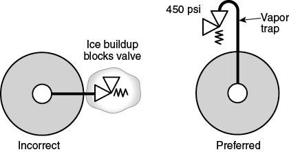
137
138 NFPA 55: Chapter 16, Liquid Nitrous Oxide Systems Compressed Gas Association, Inc. Chapter 16 Liquid Nitrous Oxide Systems 16.1 General. The storage, use, and handling of liquid nitrous oxide in bulk systems shall be in accordance with the provisions of this chapter and Chapters 1 through 7 as applicable Application. A bulk nitrous oxide system used in medical gas applications shall be in accordance with NFPA 99 in addition to the provisions stated herein Location of Bulk Nitrous Oxide Systems. Bulk nitrous oxide systems shall be located in accordance with one of the following: (1) Above ground and outdoors in accordance with Table 16.2 (2) Indoors or in courts in accordance with the following requirements: (a) The pressure relief valve shall be sized for indoor installation and for possible engulfment in fire in accordance with the provisions of CGA S-1.3, Pressure Relief Device Standards Part 3 Stationary Storage Containers for Compressed Gases. (b) All relief devices shall be vented outdoors to a location with sufficient ventilation to prevent the accumulation of nitrous oxide and to eliminate the hazard of asphyxiation. (c) The minimum separation distances of the outlet of relief device vent piping from exposures in 16.2(2)(b) shall meet the requirements of Table (d) All relief devices and vents for installations in courts as defined in shall be piped outdoors to a safe, well-ventilated area, and the area around the container shall be ventilated in accordance with Section
139 NFPA 55: Chapter 16, Liquid Nitrous Oxide Systems Compressed Gas Association, Inc. Table 16.2 Minimum Separation Distance Between Outdoor Stationary Insulated Liquid Nitrous Oxide Containers and Exposures Minimum Distance Exposure ft m (1) Buildings of Types I and II construction as defined by the building code 1.3 (2) Buildings of Types III, IV, or V construction as defined by the building code (3) Wall openings as measured from high-pressure gas or liquefied gas regulators, pressure relief devices, vaporizers, manifolds, and interconnected piping 10 3 (4) Property lines (5) Public sidewalks 10 3 (6) Public assembly (7) Areas occupied by nonambulatory patients as measured from the primary pressure relief device discharge vent and from filling and vent connections (8) Parked vehicles 10 3 (9) Exterior walls that encroach on the container to form a court with three or more sides (See ) (10) All classes of flammable and combustible liquids above ground (See ) (a) 0 gal to 1000 gal (0 L to 3785 L) (b) Over 1000 gal (3785 L) (11) All classes of flammable and combustible liquids in belowground tanks or vaults (a) Horizontal distance from nitrous oxide storage container to tank or vault (b) Horizontal distance from nitrous oxide storage container to filling and vent connections or other openings to tank or vault (12) Flammable gases above ground (a) Liquefied hydrogen (any quantity) (b) Flammable liquefied gases not exceeding 1000 gal (3.78 m 3 ) or dissolved or nonliquefied gases not exceeding 25,000 ft 3 (693 m 3 ) at reference conditions (c) Flammable gases or liquids at capacities greater than those given in 12(b) (13) Rapidly burning solids including, but not limited to, excelsior, paper, or combustible waste (14) Slowly burning solids including, but not limited to, heavy timber or coal (15) Horizontal distance from the vertical plane below the nearest overhead electrical wire * Container Design. Storage vessels shall be designed, constructed, and tested in accordance with the appropriate requirements of the ASME Boiler and Pressure Vessel Code, Section VIII, Division 1, Rules for Construction of Pressure Vessels Pressure Relief Devices Containers used for liquid nitrous oxide shall be equipped with pressure relief devices piped from the uppermost part of the containers and communicating with the vapor space Containers shall have pressure relief devices designed and provided in accordance with CGA S-1.3, Pressure Relief Device Standards Part 3 Stationary Storage Containers for Compressed Gases, for stationary tanks
140 NFPA 55: Chapter 16, Liquid Nitrous Oxide Systems Compressed Gas Association, Inc. Relief valves shall be sized, operated, and maintained per Each bulk tank shall have a minimum of two active safety relief devices sized per CGA S * The relief valve system shall be designed to meet the ASME Boiler and Pressure Vessel Code, Section VIII, Division 1, Rules for Construction of Pressure Vessels requirements to allow for proper maintenance and servicing of the devices * Non-reclosing relief devices shall not be used in nitrous oxide bulk tank service Pressure relief devices shall be located to minimize tampering, damage, and obstruction to flow The inlet and outlet of the relief devices shall not be blocked by a valve or plug during normal operation Vent Pipe Systems Pressure relief devices shall be piped to the outdoors where the discharge will not impinge on the structure, the personnel, or the means of egress and will not create a hazardous concentration of nitrous oxide * Vent piping systems serving pressure relief devices shall be protected from water intrusion to prevent moisture or solid nitrous oxide from collecting and freezing and interfering with the operation of the pressure relief device Vent piping systems serving pressure relief devices shall be designed to prevent backflow restrictions exceeding 10 percent backpressure on the pressure relief device under full flow conditions Pressure Level Indicators and Fill Connections. Containers shall be provided with a pressure gauge and a contents level gauge or other device capable of indicating the quantity of liquid nitrous oxide These devices shall be designed for the temperatures and pressures associated with liquid nitrous oxide service * 3
141 NFPA 55: Chapter 16, Liquid Nitrous Oxide Systems Compressed Gas Association, Inc. Where containers are in locations remote from the filling connection, a means to determine whether the containers have been filled to their design capacity shall be provided The liquid and vapor fill connections shall comply with CGA V-6, Standard Bulk Refrigerated Liquid Transfer Connections Dust covers and caps shall be provided for the fill connections to prevent contaminant infiltration The liquid fill connection shall be CGA N2O-15, and the vapor return connections shall be CGA N2O Insulation Insulated bulk liquid containers shall be vacuum insulated or mechanically insulated with an external vapor barrier Exposed insulating materials shall be noncombustible * Insulation such as polyurethane foam having a flame spread rating of 25 or less shall be permitted to be used if fully covered with a protective metal or other noncombustible jacket Non-vacuum-insulated tanks shall have an internal cooling coil operated with refrigerant to maintain nitrous oxide as a liquefied gas * The refrigerant shall not be allowed to come in contact with the nitrous oxide Container Installation Foundations and Supports Foundations shall be designed to withstand soil and frost conditions as well as any anticipated seismic, snow, wind, or hydrostatic loading under operating conditions Stationary containers shall be provided with noncombustible concrete or masonry foundations or structural steel supports on firm concrete or masonry foundations. 4
142 NFPA 55: Chapter 16, Liquid Nitrous Oxide Systems Compressed Gas Association, Inc Containers shall be located so there is no fire or open flame within 25 ft (7.6 m) (see Table 16.2) A concrete or noncombustible delivery vehicle unloading spill pad shall be provided The unloading spill pad shall be kept free of grease and oil or other hydrocarbons The unloading spill pad shall have minimum dimensions of 12 ft 12 ft (3.6 m 3.6 m) Fire Barrier Walls The distances shown in items 2, 4, 5, 8, and 10 through 14 of Table 16.2 shall not apply where a fire barrier wall having a minimum fire resistance of 2 hours interrupts the line of sight between uninsulated portions of the bulk storage system and the exposure Fire barrier walls shall comply with the requirements of through * Security Nitrous oxide containers and systems shall limit access to authorized personnel only Locations shall be locked when not attended by authorized personnel Perimeter security shall have a minimum height of 6 ft (1.8 m) and lockable gates * A warning sign shall be installed to indicate the hazards of nitrous oxide on the perimeter security enclosure so it can be easily seen by anyone approaching the enclosure * Enclosures shall be designed so as not to restrict or reduce natural air flow Bollards or barriers shall be used to prevent unauthorized vehicle intrusion in accordance with Section
143 NFPA 55: Chapter 16, Liquid Nitrous Oxide Systems Compressed Gas Association, Inc. Area lighting shall be provided to provide night security and to facilitate night deliveries and maintenance Materials of Construction * Materials in contact with nitrous oxide shall be suitable for the full range of temperatures and pressures to which they shall be subjected during operation Nonmetals * Nonmetallic materials shall be compatible with nitrous oxide and shall be used only as required Nonmetallic materials used at pressures greater than 435 psi (3000 kpa) shall conform to CGA G-4.10, Design Considerations to Mitigate the Potential Risks of Toxicity When Using Nonmetallic Materials in High Pressure Oxygen Breathing Gas Systems Piping Systems Piping and tubing shall conform to ANSI B31.3, Standard Code for Chemical Plant and Petroleum Refinery Piping Nitrous oxide piping shall be located and supported to protect against damage from strain on piping and fittings; the effects of expansion, contraction, and vibration; mechanical damage; and heat sources Piping, tubing, and hoses and fittings shall be designed to a bursting pressure of at least 4 times the system design pressure Pressure Relief Devices Piping systems shall be protected by a pressure relief device set to function at no greater than 50 percent over the normal operating pressure of the system All pressure relief devices shall discharge outside in a well-ventilated area * Pressure relief devices shall be installed so rain and condensation do not accumulate in the device
144 NFPA 55: Chapter 16, Liquid Nitrous Oxide Systems Compressed Gas Association, Inc. Pressure relief devices shall be positioned so they will not injure people in the vicinity where they discharge Vaporizers and Heaters * Vaporizers and heaters shall use only indirect means of heating such as steam, air, vapor, or other nonreactive materials such as solids or liquids The heating medium for nitrous oxide vaporizers shall be limited to 300 F (149 C) Electric Vaporizers and Heaters Direct-contact electric heater elements shall not be permitted Electric vaporizers shall be electrically grounded Pumps Pump design and installation shall avoid sources of heat or sparks that could lead to an ignition or initiate a decomposition reaction Pump bearings shall not be lubricated with nitrous oxide Material combinations of moving and stationary parts shall be selected to ensure a low probability of ignition or spark generation The pump shall be separated from the pump motor or power source by an open air space * Dry Run Protection Pump control systems shall have an interlock that authorizes operation only after the pump has been properly cooled down and filled with liquid The pump shutdown system shall be actuated by one or more of the following: (1) Abnormal differential pressure 7
145 (2) Elevated temperature (3) High motor current (4) A suitable liquid flow measuring device 16.8 Strainers and Filters NFPA 55: Chapter 16, Liquid Nitrous Oxide Systems Compressed Gas Association, Inc. Strainers or filters shall be installed to prevent the migration of particles within specific devices (e.g., compressors, pumps) Gaseous nitrous oxide shall be filtered using mesh sizes ( µm) Mesh filters or strainers made from high nickel alloys such as Monel, Inconel, nickel 200 alloys, or high copper alloys, such as brass, shall be permitted because of their increased resistance to oxidizer fires Glue or other combustibles shall not be permitted to be used at pressures greater than 145 psi (1000 kpa) Flow Meters * Thermal mass flow meters with exposed heater elements shall not be used Cleaning Equipment used in a bulk nitrous oxide system shall be cleaned in accordance with the requirements of CGA G-4.1, Cleaning Equipment for Oxygen Service, to remove oil, grease, solvents, particulates, or other oxidizable materials before the system is placed in service Lubricants that can come in contact with nitrous oxide shall be oxygen compatible Carbon dioxide equipment shall not be used in nitrous oxide service unless a conversion process has been followed for the change of service Any conversion shall consider design, materials of construction, insulation, cleanliness, lubricants, seals, and potential contact with high temperatures in accordance with Maintenance Procedures. 8
146 NFPA 55: Chapter 16, Liquid Nitrous Oxide Systems Compressed Gas Association, Inc Nitrous oxide equipment shall be maintained by qualified and properly trained personnel in a routine, controlled, and safe manner following written procedures Hot Work A hot work permit shall be issued and approved by a person knowledgeable in the properties of nitrous oxide for welding or other hot work The system shall be purged with air or inert gas prior to welding or other hot work Hot work shall not be performed on any equipment containing nitrous oxide, and all equipment shall be purged with an inert gas or air prior to hot work Medical installations shall be purged with medically certified inert gases prior to any hot work to prevent the formation of oxides It shall not be permitted to weld, braze, or strike an arc on any pipe, cylinder, or vessel that contains nitrous oxide * Heat from an open flame or a hot air gun shall not be applied to any part of a nitrous oxide installation to de-ice or release threaded couplings Hot work shall not be performed within 3 ft (1 m) of a section of piping that contains nitrous oxide Small Insulated Liquid Nitrous Oxide Indoor Systems. (Reserved) 9
147 NFPA 55: Chapter 16, Liquid Nitrous Oxide Systems Compressed Gas Association, Inc. 10
148 National Fire Protection Association Report 9 of 75 12/9/ :04 AM Second Revision No. 20-NFPA [ Section No. A ] A Health Care Facilities. Health care facilities include, but are not limited to, hospitals, nursing homes, limited care facilities, clinics, medical and dental offices, and ambulatory health care centers, whether permanent or movable. This definition applies to normal, regular operations and does not pertain to facilities during declared local or national disasters. A health care facility is not a type of occupancy classification as defined by NFPA 101. Therefore, the term health care facility should not be confused with the term health care occupancy. All health care occupancies (and ambulatory health care occupancies) are considered health care facilities: however, not all health care facilities are considered health care occupancies, as health care facilities also include ambulatory health care occupancies and business occupancies. [99, ] Submitter Information Verification Submitter Full Name: [ Not Specified ] Organization: [ Not Specified ] Street Address: City: State: Zip: Submittal Date: Wed Jun 18 17:37:43 EDT 2014 Committee Statement Committee Statement: Update of extract material from NFPA 99. Note that only annex material is updated. Response Message:

 from external fire exposure.")
149 National Fire Protection Association Report Second Revision No. 36-NFPA [ Section No. A ] A Figure A serves to illustrate the separation distances between bulk oxygen systems and exposures. Figure A Distances Between Bulk Oxygen Systems and Exposures. These distances do not apply where fire barriers having a minimum fire resistance rating of 2 hours interrupt the line of sight between uninsulated portions of the bulk oxygen storage installation and the exposure. The fire barriers protect uninsulated oxygen storage containers or supports, control equipment, and system piping (or parts thereof) from external fire exposure. Liquid oxygen storage containers are insulated. Such containers can provide line-of-sight protection for uninsulated system components. Interruption of the line of sight means that an eye on any part of the uninsulated portion of the bulk oxygen storage installation cannot see any part of the exposure. Supplemental Information File Name G55-3r2.jpg Description Figure A revised Submitter Information Verification Submitter Full Name: [ Not Specified ] Organization: [ Not Specified ] Street Address: City: State: Zip: Submittal Date: Mon Jul 14 14:06:12 MDT of 75 12/9/ :04 AM
150 National Fire Protection Association Report 1 of 75 12/9/ :04 AM Committee Statement Committee Statement: Add walls in the diagram to match the requirements in the text of the code Add a wall in the 50' line to the rapidly burning solids dumpster. Add a wall in the 50' line to the Buildings of Type III, IV, and V construction. Spelling correction in lower left corner "paving and expansion joint fillers." joint Response Message: Public Comment No. 1-NFPA [Section No. A.9.3.2]

151
FLAMMABLE GASES AND FLAMMABLE CRYOGENIC FLUIDS
 CHAPTER 35 FLAMMABLE GASES AND FLAMMABLE CRYOGENIC FLUIDS SECTION 3501 GENERAL 3501.1 Scope. The storage and use of flammable gases shall be in accordance with this chapter. Compressed gases shall also
COMPRESSED GASES CHAPTER 53
 CHAPTER 53 COMPRESSED GASES SECTION 5301 GENERAL 5301.1 Scope. Storage, use and handling of compressed gases in compressed gas containers, cylinders, tanks and systems shall comply with this chapter, including
Public Comment No. 39-NFPA [ Section No ] Statement of Problem and Substantiation for Public Comment Related Item
![Public Comment No. 39-NFPA [ Section No ] Statement of Problem and Substantiation for Public Comment Related Item](/thumbs/83/88066128.jpg "Public Comment No. 39-NFPA [ Section No ] Statement of Problem and Substantiation for Public Comment Related Item") National Fire Protection Association Report of 66 http://submittals.nfpa.org/terraviewweb/contentfetcher?commentpara... 8/12/2014 12:07 PM Public Comment No. 39-NFPA 55-2014 [ Section No. 2.3.3 ] 2.3.3
National Fire Protection Association Report of 66 http://submittals.nfpa.org/terraviewweb/contentfetcher?commentpara... 8/12/2014 12:07 PM Public Comment No. 39-NFPA 55-2014 [ Section No. 2.3.3 ] 2.3.3
 National Fire Protection Association Report http://submittals.nfpa.org/terraviewweb/contentfetcher?commentparams=%28comment... Page 1 of 2 1/16/2014 Committee Input No. 104-NFPA 55-2013 [ Global Input
Compressed Gas Cylinders - Guideline
 Environmental Health and Safety Compressed Gas Cylinders - Guideline Date of Issuance: 1/10/18 Revision Number: Initial Revision Date: Prepared by: EH&S 1. Purpose Carnegie Mellon University has developed
CITY AND COUNTY OF DENVER CR&CF RISK UNIT Compressed Gas Safety Standard
 CITY AND COUNTY OF DENVER CR&CF RISK UNIT 65.5.11 Compressed Gas Safety Standard 1.0 Introduction 2.0 Scope This standard has been developed to protect all City and County of Denver employees and contractors
CITY AND COUNTY OF DENVER POLICY DENVER FIRE DEPARTMENT
 Reference: IFC, Denver Amendments, NFPA Approved: Joseph L. Gonzales, Division Chief, Fire Prevention and Investigation Division Number: IFC- 3001-1 Effective Date: February 1, 2012 Page 1 of 5 This policy
Section 1.3: PRESSURE VESSEL COMPONENTS AND SYSTEMS AND COMPRESSED GAS CYLINDERS
 Section 1.3: PRESSURE VESSEL COMPONENTS AND SYSTEMS AND COMPRESSED GAS CYLINDERS TABLE OF CONTENTS Page A. Regulations, Standards and References 1.3-2 B. Scope 1.3-2 C. Design Features for the Storage
Savard Labor & Marine Staffing, Inc. Compressed Gas Safety Program Rev3/14
 Compressed Gas Safety Program Purpose: The purpose of this safety policy and procedure is to establish guidelines for the protection and safety of this company s employees who handle and use compressed
TYPICAL TOXIC GAS SYSTEM INSPECTION VIOLATIONS
 TYPICAL TOXIC GAS SYSTEM INSPECTION VIOLATIONS The following is a list of typical violations often found by inspectors and a generic solution. You can use this list to improve the safety of your facility,
CITY AND COUNTY OF DENVER POLICY DENVER FIRE DEPARTMENT. Number: 2015 IFC Effective Date: February 1, 2017 Page 1 of 5
 Subject: COMPRESSED GAS Reference: IFC, Denver Amendments, NFPA Approved: Manuel Almaguer Division Chief, Fire Prevention Division Number: 2015 IFC- 5301-1 Effective Date: February 1, 2017 Page 1 of 5
I. Subject: Compressed gas cylinders, regulators, and portable liquid systems.
 I. Subject: Compressed gas cylinders, regulators, and portable liquid systems. II. Objective: To provide safe and effective use, storage, and transport of therapeutic gases. II. Procedure: A. Compressed
ANNEX AMENDMENTS TO THE INTERNATIONAL CODE FOR FIRE SAFETY SYSTEMS (FSS CODE) CHAPTER 15 INERT GAS SYSTEMS
 CHAPTER 15 INERT GAS SYSTEMS") Annex 3, page 2 ANNEX AMENDMENTS TO THE INTERNATIONAL CODE FOR FIRE SAFETY SYSTEMS (FSS CODE) CHAPTER 15 INERT GAS SYSTEMS The text of existing chapter 15 is replaced by the following: "1 Application This
Annex 3, page 2 ANNEX AMENDMENTS TO THE INTERNATIONAL CODE FOR FIRE SAFETY SYSTEMS (FSS CODE) CHAPTER 15 INERT GAS SYSTEMS The text of existing chapter 15 is replaced by the following: "1 Application This
Cal/OSHA T8 CCR 1536 Cal/OSHA T8 CCR 4799 Cal/OSHA T8 CCR 4845 Cal/OSHA T8 CCR 4848
 Cal/OSHA Gas Systems for Welding GAS WELDING Cal/OSHA T8 CCR 1536 Cal/OSHA T8 CCR 4799 Cal/OSHA T8 CCR 4845 Cal/OSHA T8 CCR 4848 When performing gas welding, the following precautions, work procedures,
This written Compressed Gas Plan is kept at the corporate office and in the written Safety & Health Program.
 Safety & Health Program 10627 Midwest Industrial Boulevard, St. Louis, MO Phone: 314-785-6425 Fax: 314-785-6426 Compressed Gas Plan Purpose It is the policy of EMA to permit only trained and authorized
1 Exam Prep NFPA 99 Health Care Facilities Questions and Answers (Plumbing Contractor)
") 1 Exam Prep NFPA 99 Health Care Facilities Questions and Answers (Plumbing Contractor) 1. According to NFPA 99, SCFM is an acronym for. a) Surface Conditions at Fahrenheit Mercury b) Standard Conditions
1 Exam Prep NFPA 99 Health Care Facilities Questions and Answers (Plumbing Contractor) 1. According to NFPA 99, SCFM is an acronym for. a) Surface Conditions at Fahrenheit Mercury b) Standard Conditions
[Reserved] Packagings ICC 3 1 3AA 3AL 3AX 3A480X 3AAX
![[Reserved] Packagings ICC 3 1 3AA 3AL 3AX 3A480X 3AAX](/thumbs/80/80792632.jpg "[Reserved] Packagings ICC 3 1 3AA 3AL 3AX 3A480X 3AAX") 173.300 [Reserved] 173.301 General requirements for shipment of compressed gases and other hazardous materials in cylinders, UN pressure receptacles and spherical pressure vessels. (a) General qualifications
173.300 [Reserved] 173.301 General requirements for shipment of compressed gases and other hazardous materials in cylinders, UN pressure receptacles and spherical pressure vessels. (a) General qualifications
Compressed Gases Safety Program
 Compressed Gases Safety Program Summary: Compressed gas cylinders can present a variety of hazards due to their pressure and /or contents. This program covers requirements which must be followed for the
Compressed Gases Storage and Handling Safety Policy. Individual Unit Function: Safety Procedure No.: SOP-0103 Page: 1 of 6
 Procedure No.: SOP-0103 Page: 1 of 6 MIDGA Reviewed: 07/09/18 Effective: 1/14/98 Supersedes: Original Preparer: Owner: Approver: Safety Safety Safety 1. PURPOSE The purpose of this procedure is to establish
Compressed Gases and Cryogens
 Compressed Gases and Cryogens University of Tennessee Safety Guide HM-011 Document Contact: EHS Date effective: January 1, 2009 Revision Date: October 1, 2015 Purpose This guideline adheres to the Occupational
Public Comment No. 4-NFPA [ Section No ] Statement of Problem and Substantiation for Public Comment
![Public Comment No. 4-NFPA [ Section No ] Statement of Problem and Substantiation for Public Comment](/thumbs/95/124123845.jpg "Public Comment No. 4-NFPA [ Section No ] Statement of Problem and Substantiation for Public Comment") Public Comment No. 4-NFPA 318-2013 [ Section No. 2.3.4 ] 2.3.4 ASTM Publications. ASTM International, 100 Barr Harbor Drive, P.O. Box C700, West Conshohocken, PA 19428-2959. ASTM D5, Standard Test Method
Public Comment No. 4-NFPA 318-2013 [ Section No. 2.3.4 ] 2.3.4 ASTM Publications. ASTM International, 100 Barr Harbor Drive, P.O. Box C700, West Conshohocken, PA 19428-2959. ASTM D5, Standard Test Method
GUIDELINES FOR CONDUCTING HYDROGENATION REACTIONS
 Page 1 of 5 GUIDELINES FOR CONDUCTING 1. Definition of Hydrogenation and Hydrogenolysis Reactions Hydrogenation reactions are synthetic transformations involving hydrogen, metallic catalysts (such as nickel,
Gas Cabinets and Valve Manifold Boxes: Applying CGA G13- Rev 2015 to Gas Delivery Equipment
 Gas Cabinets and Valve Manifold Boxes: Applying CGA G13- Rev 2015 to Gas Delivery Equipment The Standard Governing the Storage & Use of Silane: Compressed Gas Association s Publication CGA G-13 2015: Storage
PURPOSE OF THE POLICY
 Title: Safe Storage, Handling, Use and Disposal Procedures of Compressed Gas Cylinders Effective Date: November 2005 Revision Date: March 1, 2017 Issuing Authority: Responsible Officer: VP, Capital Projects
STORAGE OF COMPRESSED GAS CYLINDERS (SAF-SPI-15)
") 1. PURPOSE: This SPI has been developed to ensure compliance to government regulations and to provide clear standards for storage of compressed gases. 2. CONTEXT The storage of compressed gases is legislated
1. PURPOSE: This SPI has been developed to ensure compliance to government regulations and to provide clear standards for storage of compressed gases. 2. CONTEXT The storage of compressed gases is legislated
WELDING AND OTHER HOT WORK
 CHAPTER 26 WELDING AND OTHER HOT WORK SECTION 2601 GENERAL 2601.1 Scope. Welding, cutting, open torches and other hot work operations and equipment shall comply with this chapter. Exception: Hot work on
Section 20 TABLE OF CONTENTS Pressurized Equipment and Systems. 20.A General B Compressed Air and Gas Systems
 Section 20 TABLE OF CONTENTS Pressurized Equipment and Systems Section: Page 20.A General... 20-1 20.B Compressed Air and Gas Systems... 20-4 20.C Boilers and Systems... 20-7 20.D Compressed Gas Cylinders...
WHAT IS GAS TANK/CYLINDER?
 Introduction To use compressed gas cylinders safely, it is important that they are stored properly, handled correctly, used with the correct equipment, and that the properties of the gases they contain
Material Handling and Storage of compressed gases and Air equipment
 Material Handling and Storage of compressed gases and Air equipment Compressed gases can be toxic, flammable, oxidizing, corrosive, inert, or some combination of these hazards. Compressed gas cylinders
TABLE OF CONTENTS PART 2 - CONFINED SPACES
 May 11, 2006 TABLE OF CONTENTS PART 2 - CONFINED SPACES Page DEFINITIONS... 2-1 GENERAL... 2-2 RESPONSIBILITIES... 2-2 HAZARD ASSESSMENT AND WORK PROCEDURES... 2-3 IDENTIFICATION AND ENTRY PERMITS... 2-3
Piped Air SCBA Refilling System Standard
 WALT WHITE Fire Chief 5770 Freeport Blvd., Suite 200 Sacramento, CA 95822-3516 Ph: (916) 808-1300 Fax: (916) 808-1629 www.sacfire.org Piped Air SCBA Refilling System Standard SCOPE: This specification
Installation of Ballast Water Management Systems
 (Sept 2015) (Rev.1 May 2016) Installation of Ballast Water Management Systems 1. Application In addition to the requirements contained in BWM Convention (2004), the following requirements are applied to
PRESSURIZED EQUIPMENT AND SYSTEMS
 SECTION 20 PRESSURIZED EQUIPMENT AND SYSTEMS 20.A GENERAL 20.A.01 Inspections and tests - general. a. Pressurized equipment and systems shall be inspected and performance tested before being placed in
UTMB RESPIRATORY CARE SERVICES GUIDELINES Respiratory Care Services Medical Gas Cylinder Storage, Use and Transport
 Page 1 of 4 I. Title Medical Gas. II. III. IV. Policy This policy applies to all departments and areas where medical gases are used, stored or transported for patient care activities. Respiratory Care
Compressed Gas Cylinder Safety Program April 4, 2017
 1.0 INTRODUCTION Compressed Gas Cylinder Safety Program April 4, 2017 1.1 Purpose Indiana University Environmental Health and Safety (IUEHS) has developed this Program to cover general procedures for the
Process Name Compressed Gas Cylinders Program
 CNM WAY PROCESS CNM Process Name Compressed Gas Cylinders Program (07/11/2018 Revision) Overview of Compressed Gas Cylinders Program Purpose: To prevent injury from failure of compressed gas cylinders
Handling and Storage of Gases
 Handling and Storage of Gases Learning Outcome When you complete this module you will be able to: Describe the procedures for safe storage and handling of cylinders containing gases. Learning Objectives
Transport of gas tanks for motor vehicles
 Committee of Experts on the Transport of Dangerous Goods and on the Globally Harmonized System of Classification and Labelling of Chemicals Transport of gas tanks for motor vehicles Submitted by the expert
Management Plan for Compressed Gas
 IEA, INC. N E W P R A G U E A R E A S C H O O L S I S D # 7 2 1 A Service-Disabled Veteran-Owned Small Business Contact Us: BROOKLYN PARK OFFICE 9201 W. BROADWAY, #600 BROOKLYN PARK, MN 55445 763-315-7900
KENNECOTT UTAH COPPER CORPORATION SAFETY AND HEALTH STANDARDS COMPRESSED GAS
 KENNECOTT UTAH COPPER CORPORATION SAFETY AND HEALTH STANDARDS COMPRESSED GAS Effective Date: 08/07/14 Standard: 16.15 Document Number: KUCSH0070 Rev: 05 007016.15.1 INTRODUCTION 16.15.1.1 This standard
MEDICAL EQUIPMENT CATALOG
 THE MOST TRUSTED MEDICAL EQUIPMENT IN NORTH AMERICA MEDICAL EQUIPMENT CATALOG Total Components Including Bulk Oxygen Supply, Back up and Delivery Equipment Designs for High Pressure, Liquid or Bulk Applications
Laboratory Safety Committee
 Laboratory Safety Committee Compressed Gas Cylinder Policy Purpose Compressed gas cylinders are an important component of many research laboratories. Wide varieties of gases are packaged in compressed
Compressed Gasses Safety
 COMPRESSED GASES SAFETY Last Modified: APR 2015 1 of 6 Compressed Gasses Safety 1 PURPOSE To provide guidelines for transport, storage, handling, and use of cylinders containing compressed gas. 2 SCOPE
U.S. CONCRETE, INC. SAFETY POLICY and PROCEDURE MANUAL
 SAFE -14 Page 1 of 8 U.S. CONCRETE, INC. SAFETY POLICY and PROCEDURE MANUAL FUNCTION Safety TOPIC Hotwork Permit Program OBJECTIVE(S): GENERAL POLICY: To provide a work atmosphere that is conducive to
General Precautions for handling compressed gases
 General Precautions for handling compressed gases Introduction Compressed gas cylinders can be extremely hazardous when misused or abused. Compressed gas cylinders can present a variety of hazards due
Hydrogen in Air % to 2%
 Kele part# GAS-H2-2 Emergency Contact: Chemtrec (800) 424-9300 Or rco (208) 336-1643 1125 West Amity Road Boise, ID 83705 (208) 336-1643 Hydrogen in Air 0.0001% to 2% Identification Product Name: Hydrogen
Carnegie Mellon University. Toxic and Highly Toxic Gas Handling Program
 Carnegie Mellon University Toxic and Highly Toxic Gas Handling Program Toxic and Highly Toxic Gas Handling Program Scope and Background The Carnegie Mellon University Toxic and Highly Toxic Gas Handling
Section 35 Brieser Construction SH&E Manual
 Brieser Construction SH&E Manual August 2017 Assure that employees handling compressed gases are adequately trained in the inherent hazards of the cylinders and their contents, as well as proper handling,
SAFETY POLICY AND PROCEDURE MANUAL All Euramax Subsidiaries. Number K-3.0 Welding Safety Procedures
 Number K-3.0 Issued: 1/2009 Revised: 3/2016 Page 1 of 3 1.0 PURPOSE: To standardize procedures associated with production and maintenance welding and to minimize the potential risk of accident or injury
FLAMMABLE & COMBUSTIBLE LIQUIDS PROGRAM
 FLAMMABLE & COMBUSTIBLE LIQUIDS PROGRAM 1.0 PURPOSE This program applies to employees, visitors and contractors (persons) for the purpose of articulating safe work practices when working with and around
DSEAR- Storage, Use and handling of gas cylinders guidance.
 OHSS: Storage, Use and handling of gas cylinders guidance 202 DSEAR- Storage, Use and handling of gas cylinders guidance. Contents Introduction... 2 General recommendations for storage, use and handling....
Inert Air (N2) Systems Manual
 Systems Manual") INSTRUCTION MANUAL Inert Air (N2) Systems Manual N2-MANUAL 2.10 READ AND UNDERSTAND THIS MANUAL PRIOR TO OPERATING OR SERVICING THIS PRODUCT. GENERAL INFORMATION Positive pressure nitrogen gas pressurizing
INSTRUCTION MANUAL Inert Air (N2) Systems Manual N2-MANUAL 2.10 READ AND UNDERSTAND THIS MANUAL PRIOR TO OPERATING OR SERVICING THIS PRODUCT. GENERAL INFORMATION Positive pressure nitrogen gas pressurizing
UNIVERSITY OF ROCHESTER ENVIRONMENTAL HEALTH & SAFETY
 Revision No.: New Page 1 of 9 I. PURPOSE It is a requirement that all University of Rochester employees who handle compressed gases understand the health and safety hazards of the compressed gas cylinders,
WELDING, CUTTING AND BRAZING
 - 1 - WELDING, CUTTING AND BRAZING Are only authorized and trained personnel permitted to use welding, cutting or brazing equipment? Does each operator have a copy of the appropriate operating instructions
SERIES & NO. SMI - 115
 1 of 7 1.0 PURPOSE To provide a system of handling and storing compressed gas and fuel gas cylinders. This instruction details the materials and methods used to handle and store cylinders. All contractors
Safety Data Sheet. Zero Air 1 PRODUCT AND COMPANY IDENTIFICATION. Manufacturer NorLab a division of Norco 898 W. Gowen Rd.
 Number: NLB 255 Page 1 of 5 1 PRODUCT AND COMPANY IDENTIFICATION Manufacturer NorLab a division of Norco 898 W. Gowen Rd. Boise, ID 8375 Contact: Phone: Fax: Web: Quality Dept. 28-336-1643 28-433-616 www.norlab-gas.com
CHAPTER 1 General Part
 1 (Garuda Emblem) Notification of Ministry of Industry Re: Safety measure for gas business operation B.E. 2548 (2005) ---------------------------- By the virtue of clause 18 and clause 19 of the Ministerial
Welding, Cutting, and Brazing
 Welding, Cutting, and Brazing Hazards of Welding Operations Fire hazards Metal splatter Electric shock Explosion hazards Released gases Radiant energy Where would these hazards be found on oil and gas
Refrigerant R170 - ETHANE
 Material Safety Data Sheet Refrigerant R170 - ETHANE Revision 09/04 1 CHEMICAL PRODUCT AND COMPANY IDENTIFICATION Advanced Gas Technologies 1401 Stauffer Road Palm, PA 18070 Telephone Number: (215) 541-4116
New Hampshire Public Utilities Commission CFR 49 Part 192 Regulations. MINIMUM Pipeline Safety Regulations
 New Hampshire Public Utilities Commission CFR 49 Part 192 Regulations MINIMUM Pipeline Safety Regulations Application for Jurisdictional LPG Operators 1 Pipeline Safety Regulations 49 CFR Part 192 (NOTE:
MSC Guidelines for Pressure Vessels
 References: a. 46 CFR Part 54 Pressure Vessels S. T. Brady, CDR, Chief, Engineering Division b. ASME Boiler and Pressure Vessel Code (BPVC), Section VIII, Division 1, (1998 Edition) c. Navigation and Inspection
Installation Operating Instructions for Duplex Manual Manifolds PX-TMD Series
 Introduction Powerex manifolds are cleaned, tested and prepared for the indicated gas service and are built in accordance with the Compressed Gas Association guidelines. The manifold consists of a regulator
Periodical surveys of cargo installations on ships carrying liquefied gases in bulk
 (June 1999) (Rev.1 Mar 2006) (Rev.2 May 2007) (Rev.3 Mar 2010) (Corr.1 Feb 2011) (Rev.4 Oct 2013) Periodical surveys of cargo installations on ships carrying liquefied gases in bulk 1 General 1.1 Scope
CLEANING, INSPECTION, AND TESTING OF SEWERS
 CLEANING, INSPECTION, AND TESTING OF SEWERS PART 1 - GENERAL 1.01 SECTION INCLUDES A. Cleaning, Inspecting, and Testing Sanitary Sewers B. Cleaning, Inspecting, and Testing Storm Sewers C. Cleaning and
CHAPTER 26 WELDING AND CUTTING
 CHAPTER 26 WELDING AND CUTTING Revised 7/2010 1 WELDING AND CUTTING Responsibilities 1. The County Safety Officer is responsible for providing appropriate safety instructions for supervisor's use on welding
Scorched Nuts Fire Art Guide
 Scorched Nuts Fire Art Guide This guide is to serve as a reference for the construction and use of flame effects while at Scorched Nuts. At this time, no pressurized effects(poofers) will be permitted
623 Series Dome Load Regulators
 ADI 3202C Certified ISO 9001 623 Series Dome Load Regulators INSTALLATION AND OPERATION INSTRUCTIONS This Equipment is intended to be installed and operated by trained personnel. Before Installing or Operating,
INSTRUCTIONS FOR MODELS SG3897 AND SG3898 CROSS PURGE ASSEMBLIES
 INSTRUCTIONS FOR MODELS SG3897 AND SG3898 CROSS PURGE ASSEMBLIES THIS BOOKLET CONTAINS PROPRIETARY INFORMATION OF ADVANCED SPECIALTY GAS EQUIPMENT CORP. AND IS PROVIDED TO THE PURCHASER SOLELY FOR USE
DF1 and DF2 Diffusers
 1550650/4 IM-P155-07 ST Issue 4 and Diffusers Installation and Maintenance Instructions 1. Safety information 2. General product information 3. Installation 4. Commissioning 5. Operation 6. Maintenance
DENVER AMENDMENT PROPOSAL 2015 INTERNATIONAL CODES
 DENVER AMENDMENT PROPOSAL 2015 INTERNATIONAL CODES NOTE: Each proposed Denver amendment to the International Codes must be justified. In order to be considered, the amendment proposal must address climate,
RESOLUTION A.567(14) adopted on 20 November 1985 REGULATION FOR INERT GAS SYSTEMS ON CHEMICAL TANKERS
 adopted on 20 November 1985 REGULATION FOR INERT GAS SYSTEMS ON CHEMICAL TANKERS") INTERNATIONAL MARITIME ORGANIZATION A 14/Res.567 16 January 1986 Original: ENGLISH ASSEMBLY - 14th session Agenda item lo(b) IMO RESOLUTION A.567(14) adopted on 20 November 1985 THE ASSEMBLY, RECALLING
INTERNATIONAL MARITIME ORGANIZATION A 14/Res.567 16 January 1986 Original: ENGLISH ASSEMBLY - 14th session Agenda item lo(b) IMO RESOLUTION A.567(14) adopted on 20 November 1985 THE ASSEMBLY, RECALLING
SAFETY DIRECTIVE 3.0 REFERENCES. 3.1 See Appendix B
 SAFETY DIRECTIVE Title: Hot Work Issuing Department: Town Manager s Safety Office Effective Date: September 1, 2014 Approved: Gilbert Davidson, Town Manager Type of Action: New 1.0 PURPOSE To provide proper
SUBSTATION MAINTENANCE ELECTRICAL OPERATING PROCEDURE
 Page 1 of 6 A. PURPOSE AND SCOPE This procedure establishes safe working practices for handling sulfur hexafluoride (SF 6 ) gas and release minimization practices. This document also specifies methods
Oxford Instruments Plasma Technology. PlasmaPro NGP80. Installation Data Sheet. Original Instructions.
 Oxford Instruments Plasma Technology www.oxford-instruments.com About this data sheet This data sheet provides basic information about the installation of a tool. Floor and wall loadings Table 1 lists
Hot Work Program. University of Wisconsin-Platteville Reviewed 4/2016
 Hot Work Program University of Wisconsin-Platteville Reviewed 4/2016 The purpose of the Hot Work Program is to establish safety procedures for employees, contractors, and subcontractors engaging in any
Standard Operating Procedure (SOP) Compressed Gas Cylinders (Original SOP from Eastern Washington University)
 Compressed Gas Cylinders (Original SOP from Eastern Washington University)") (Original SOP from Eastern Washington University) INTRODUCTION Compressed gases can be toxic, flammable, oxidizing, corrosive, inert, or some combination of these hazards. In addition to the chemical hazards,
(Original SOP from Eastern Washington University) INTRODUCTION Compressed gases can be toxic, flammable, oxidizing, corrosive, inert, or some combination of these hazards. In addition to the chemical hazards,
FV Flash Vessel Installation and Maintenance Instructions
 4041050/5 IM-P404-10 EMM Issue 5 FV Flash Vessel Installation and Maintenance Instructions 1. Safety information 2. Specific product safety information 3. Product information 4. Installation 5. Commissioning
Horizontal Bladder Tanks
 DATA SHEET Horizontal Bladder Tanks Features UL Listed and FM Approved for use with various ANSUL proportioners and foam concentrates 175 psi (12.1 bar) maximum allowable working pressure (design pressure)
COMPRESSED GAS CYLINDERS
 Title: Compressed Gas Cylinders Effective Date: 7/2/2014 Control Number: THG_0044 Revision Number: 1 Date: 10/23/2015 Annual Review Completed: 5/13/2015 CONTENTS I. PURPOSE II. SCOPE III. KEY RESPONSIBILITIES
Summary of the MRA LPG Codes of Practice
 Summary of the MRA LPG Codes of Practice COP A1 DESIGN and INSTALLATION Code COP A1 deals with above ground installations where LPG is stored under pressure at ambient temperatures in fixed vessels larger
Transport of gas tanks for motor vehicles
 United Nations Secretariat ST/SG/AC.10/C.3/2016/51 Distr.: General 30 August 2016 Original: English Committee of Experts on the Transport of Dangerous Goods and on the Globally Harmonized System of Classification
Doc No: WELDHOT Midland Engineering Co., Inc. Initial Issue Date 12/14/15 Safety Management System
 Revision Preparation: Safety Mgr Authority: President Issuing Dept: Safety Page: Page 1 of 7 PURPOSE To provide guidelines for the safe operation of welding, cutting and hot work of equipment, and to itemize
Vertical Bladder Tanks
 DATA SHEET Vertical Bladder Tanks Features UL Listed and FM Approved for use with various ANSUL proportioners and foam concentrates 175 psi (12.1 bar) maximum allowable working pressure (design pressure)
Installation Operating Instructions for Simple Duplex Manual Manifolds PX-TSD Series
 Introduction Powerex manifolds are cleaned, tested and prepared for the indicated gas service and are built in accordance with the Compressed Gas Association guidelines. The manifold consists of a regulator
Committee Input No. 59-NFPA [ Section No. 5.9 ]
![Committee Input No. 59-NFPA [ Section No. 5.9 ]](/thumbs/77/75129979.jpg "Committee Input No. 59-NFPA [ Section No. 5.9 ]") Committee Input No. 59-NFPA 54-2012 [ Section No. 5.9 ] 5.9 Overpressure Protection Devices. 5.9.1 General 1 Where required. Overpressure Where the serving gas supplier delivers gas at a pressure greater
Committee Input No. 59-NFPA 54-2012 [ Section No. 5.9 ] 5.9 Overpressure Protection Devices. 5.9.1 General 1 Where required. Overpressure Where the serving gas supplier delivers gas at a pressure greater
Field Instruction Storage, Handling, Transport and Disposal of Sulphur Hexafluoride (SF6) Gas
 Gas") 6.14 Storage, Handling, Transport and Disposal of Sulphur Hexafluoride (SF6) Gas Purpose Describe the minimum requirements for safe handling, storage, maintenance, repair, transport and disposal of equipment
6.14 Storage, Handling, Transport and Disposal of Sulphur Hexafluoride (SF6) Gas Purpose Describe the minimum requirements for safe handling, storage, maintenance, repair, transport and disposal of equipment
Draft. Not yet Approved
 201178 Part 12.5.20 Recommended Safety Instructions for LP-Gas Winter Switch Protection Devices Revised 201178 (6 Pages) A. Purpose 1. This Manual Part recommends instructions for LP-Gas systems servicing
Confined Space Entry
 Confined Space Entry Purpose The purpose of this document is to establish methods to identify confined spaces, classify them according to their risks, and establish guidelines necessary for the safe preparation,
Hotspotter. Model WB-100 Professional Series. Assembly, Testing & Operating Instructions. Safety Information:
 Hotspotter Model WB-100 Professional Series Assembly, Testing & Safety Information: Safety publications related to safe practice and use: CSA 2-94 U.S. Requirements for Hand-Held LP Torches for use with
SAFETY MANUAL FOR FLAMMABLE PRODUCT TRANSFER
 SAFETY MANUAL FOR FLAMMABLE PRODUCT TRANSFER SUPPLIMENT TO eom IMPORTANT READ THIS MANUAL BEFORE PRODUCT INSTALLATION, OPERATION, INSPECTION & MAINTENANCE Tougher and more rigid guidelines are being established
Pressure Systems Safety Regulation
 Pressure Systems Safety Regulation Introduction This document informs Faculty of the key requirements of the UK and Chinese Pressure Systems Safety regulations. The aim of these regulations is to prevent
SAFETY DATA SHEET GAS MIXTURES ARGON 75% CARBON DIOXIDE 25%
 PAGE NO. 1 of 10 1 PRODUCT AND COMPANY IDENTIFICATION 1.1 PRODUCT IDENTIFIER : 1.1.1 PRODUCT NAME 75% Argon, 25% Carbon Dioxide 1.1.2 SYNONYMS 1.1.3 CAS NUMBER 1.1.4 CHEMICAL FORMULA Argon: 7440371 Carbon
Risk Management Resources
 Risk Management Resources Machine Guarding Name: Notes: Electrical Systems: Fire Prevention Are circuit breakers accessible to personnel, protected from physical damage, and located away from ignitable
Class 2 Gases Learning Tool
 Class 2 Gases Learning Tool This work has been produced by DGL (Aust) Pty Ltd This Learner s Guide is about the skills and knowledge required to store and warehouse Class 2 Gases at DGL (Aust) facilities.
Compressed Gas Properties. Introduction. Compressed Gas Properties. Definition of a Compressed Gas
 1. Properties of gases 2. Cylinders 3. Storage of Gases 4. Regulators 5. Cryogenic Liquids Introduction All compressed gases by definition can be hazardous Know the properties of the gases you are working
Tri-Tech Medical Inc.
 Introduction Tri-Tech Medical manifolds are cleaned, tested and prepared for the indicated gas service and are built in accordance with the Compressed Gas Association guidelines. The manifold consists
G196 Series BASOTROL Redundant Combination Gas Valve with Manual Shutoff Valve
 Installation Instructions Issue Date March 13, 2013 G196 Series BASOTROL Redundant Combination Gas Valve with Manual Shutoff Valve Application The G196 valves are suitable for use with natural gas, Liquefied
SAFETY TRAINING LEAFLET 06 CARBON DIOXIDE
 SAFETY TRAINING LEAFLET 06 CARBON DIOXIDE Doc 23.06/18 EUROPEAN INDUSTRIAL GASES ASSOCIATION AISBL AVENUE DES ARTS 3-5 B 1210 BRUSSELS Tel: +32 2 217 70 98 Fax: +32 2 219 85 14 E-mail: info@eiga.eu Internet:
Periodic Survey of Fuel Installations on Ships other than Liquefied Gas Carriers utilizing gas or other low flash point fuels
 (Jan 2017) Periodic Survey of Fuel Installations on Ships other than Liquefied Gas Carriers utilizing gas or other low flash point fuels CONTENTS 1. Application 2. Special Survey 2.1 Schedule 2.2 Scope
WATER MADE EASY MARINE ENERGY MUNICIPAL INDUSTRIAL
 Capital Controls Series 71V3000 The Series 71V3000 electrically-heated vaporizer automatically vaporizes and superheats liquid chlorine, sulfur dioxide or ammonia at a rate controlled by the gas feed system.