Restriction Orifice. Single or Multi Stage Orifice to. Reduce Pressure or. Limit the Flow Rate
|
|
|
- Shona Davidson
- 6 years ago
- Views:
Transcription

1 Restriction Orifice Single or Multi Stage Orifice to Reduce Pressure or Limit the Flow Rate

2 Restriction Orifice Plates Series ROPS Principle Restriction Orifice Plates and Critical Flow Devices and their calculation, construction and application is going to described in this section; for pressure control and flow limitation which are known usually as RO and FO devices. Please consider there are differences between them, although all are known as Restrictions. Flow measurement of liquid, gas and steam according to the differential pressure principle has been recognised principle for very many years using orifice plates, venturi tubes and flow nozzles. A restriction in the pipe line creates a pressure drop if the fluid flows. The pressure drop is determined by the velocity of the fluid. The method is thoroughly described in many standards, practices and handbooks. This special use is not covered by international standards and is only indirectly mentioned in literature. However we have to separate the description in to two parts: Restriction Orifice Plates Critical Flow Devices

3 Part 1:Restriction Orifice Plates As the headline implies two main types of flow limitation exist. One type is the restriction orifice plate, which in construction and calculation follows the orifice plate, i.e. the restriction orifice plate normally has a thickness of 3-6 mm depending on the size of the tube. The discharge coefficient of the restriction orifice plate is, as for the orifice plate, approximately 0.6 according to ISO 5167 standard. For this type of restriction orifice plates the flow value through the orifice plate will vary with the pressure before and after the orifice plate. The restriction orifice plate is mostly applied in Non-critical flow limitation. This could for instance be after a control valve in order to divide the required pressure loss into two elements. This is done to reduce the noise in liquids and to avoid cavitation. It is advisable to avoid cavitation in order to protect the process elements before the restriction orifice plate in blowdown systems, and as flow limiter. The use of the expression "non-critical" must not be compared to the word "critical" in critical flow devices. Non-critical is here to be understood as non-complicated with less requirements for the accuracy.
4 Part 2: Critical Flow Devices A safe flow limitation is obtained through the application of a critical flow device. - Gas flow When a gas flow is passing through a restriction the density is reduced and the velocity of the gas flow is increased. If the downstream pressure is reduced at the same time as the upstream pressure is kept constant, then the flow quantity or Value will increase. A further reduction in the pressure will furthermore, increase the flow quantity, until the so called "Choked Flow" is reached. After this a further reduction of the pressure will not increase the flow quantity. - Liquid flow If the pressure in Vena Contracta (because of high velocity) decreases to the vaporisation pressure of the liquid, a cavitation zone is created. This cavitation zone will act as a flow limitation. What is Cavitation? Cavitation occurs frequently in liquid flow restrictions where a large pressure drop exists. When the downstream pressure is below the vaporisation pressure vapour bubbles are created. When the liquid has passed through the restriction orifice plate the area is increased, the velocity decreases, and the pressure increases. This leads to the collapse of the vapour bubbles. This collapse of the bubbles generates noise, and the plate as well as the tube will erode. It is, therefore, important to avoid a full cavitation through a liquid flow restriction. A differential pressure of DP as indicated below should be used: F l = DP/ (P 1 -P v ) < 0.7 F l = Critical flow factor P 1 = Upstream pressure P v = Vaporisation pressure (or Vapour Pressure)
?")
5 At particularly large drops in pressure more restriction orifice plates in series are used to avoid full cavitation. It means sometimes we have to use a Restriction Orifice Spool or as it is famous in piping and instrumentation: MULTI STAGE RESTRICTION ORIFICE What is Discharge Coefficient (Cd)? The discharge coefficient Cd is dependent on the Reynolds No. It has been shown by Cunningham that a standard plate constructed according to ISO 5167 cannot create a critical flow. Ward-Smith has shown theoretically that critical velocity can be obtained, when the discharge coefficient is approaching 1. The discharge coefficient is if: 1 < t/d < 7 Where t = thickness of the plate and d = bore of the plate. The ratio t/d can be reduced to 0.3, if the upstream side of the plate is very sharp. Furthermore, t/d can be increased to 10 or more, if the bore is very smooth. Below t/d = 0.3 a critical flow cannot be obtained.

6 Calculation of the thickness of the plate Apart from the determination of the thickness of the plate, with respect to the discharge coefficient, the determination must also include a calculation with regard to the strength of the plate; we call it Mechanical Calculation. Different standards can be used for the calculation, but the common standard is the ASME. According to ASME Boiler and Pressure Vessel Code section VIII div. 1 chap. UG 34 the thickness of the plate is calculated as a flat blank. Since the plate has a bore a complete calculation can be made with regard to reinforcement of the bore according to chap. UG 39 (b) of same reference. Single Stage or Multi Stage? When the required pressure drop is more than critical pressure of the fluid, we have to use two or more orifice plates queue after each other. It means we need a SPOOL instead of a simple PLATE. The calculation for each step and the layout of steps vary case by case.

7 Single Hole or Multi Hole? When flow goes through the bore, according to the Vena diameter and velocity, a sound appears. To avoid increasing this sound, sometimes, we can use several small bores instead of one single bore. This solution not only reduces the sound level, but also avoid dangerous vibration. Construction Restriction orifice plates must be sharp edged and with a cylindrical bore, i.e. without bevelling on the backside. Of course the Iranian Petroleum Standard (IPS) allows the bevelled bore with no mention to the calculation methods. Apart from this the construction details are as for standard orifice plates for insertion between RF and RTJ flanges. However, it should be considered for thick RTJ plates to have a RTJ groove in the plate instead of having the plate as a part of a seal ring. This will give a better sealing, since a standard soft seal ring can be applied.

8 Typical Draft Single Stage Restriction Orifice Plate Multi Stage Restriction Assembly Mounting style Marking NOTE : Single Stage: As same as Normal Orifice Plate; Between raised face flanges according To ANSI B16.36 or DIN 19214, Or other standards on request. Multi Stage: Normally between flanges as a Spool, also BUT WELD type is available to be welded through a pipe line. : With name plate in AISI 316 with the following inscription: TAG no., serial no., Flange Size, type, Facing and pressure rating, Inlet and Outlet Pressure, inner pipe diameter, material of construction and UPSTREAM mark. : Sound Level and Mechanical Calculation is mandatory as well as Flow or Process Calculations. Multi Stage Restriction Orifice Assembly (To avoid Vibration, Cavitation and high Sound Level in operation)


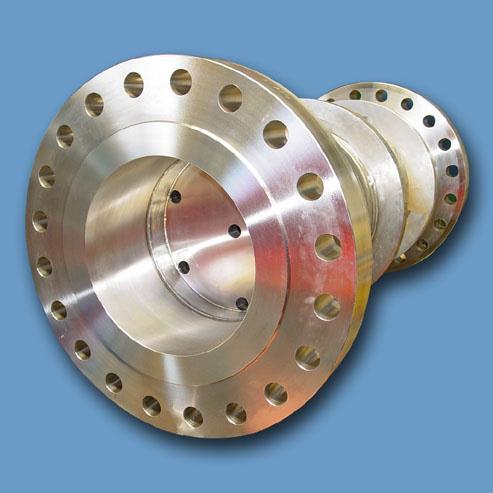
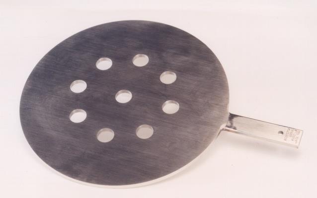
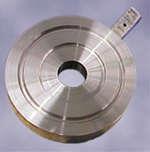
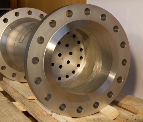
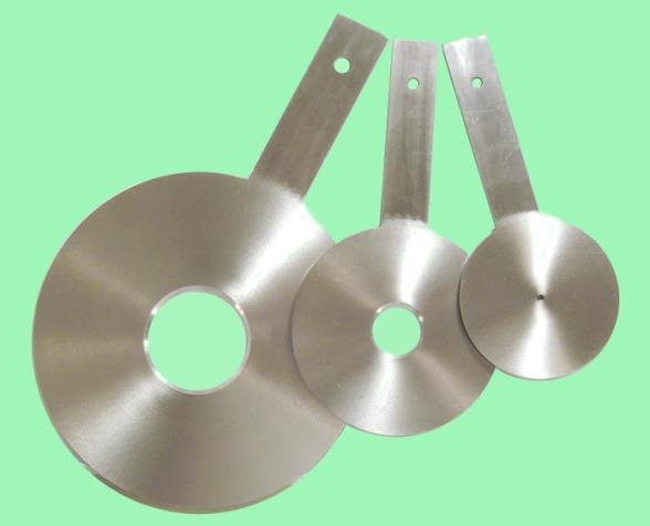
9 Some Samples of Restriction orifice, Single or Multi Stages:
The Discussion of this exercise covers the following points:
 Exercise 3-2 Orifice Plates EXERCISE OBJECTIVE In this exercise, you will study how differential pressure flowmeters operate. You will describe the relationship between the flow rate and the pressure drop
Radar, Ultrasonic and RF Level Transmitters
 Radar, Ultrasonic and RF Level Transmitters Both measures the time it takes the wave to travel between the transmitter and that reflected wave off the surface of the material to reach the transmitter again.
COMPAFLOW. Compressed Air. Volumetric flow. Gas. Mass flow. Steam. Net volumetric flow. Liquid
 Volumetric flow Compressed Air Mass flow Gas Net volumetric flow Steam Liquid Universal compact orifice flow meter combines a compact orifice flow sensor and sotiphicated converter One-piece flow sensor,
THE PROCESS OF JOINT INTEGRITY
 BOLTED JOINTS A.333 THE PROCESS OF JOINT INTEGRITY To assist in managing a process, ask yourself the following questions: why, what, who, and how? Why do we need a Flange Joint Integrity program? This
Si C132. Safety valves for pressure relief in accordance to PED, DIN/EN and ASME. Engineering GREAT Solutions
 Safety valves for pressure relief in accordance to PED, DIN/EN and ASME Engineering GREAT Solutions Si C132 Features The universal compact safety valve > 3 body seat sizes for appropriate size selection
No E. General Information. Averaging Pitot Tube Flow Sensor HITROL CO., LTD.
 No. 2000-03E Averaging Pitot Tube Flow Sensor HITROL CO., LTD. M e a s u r e m e n t Pr i n c i p l e Measurement principle of Hitbar sensor is explained below. When a Hitbar is installed in the pipeline
OVERVIEW OF THE CONVAL 10 SERVICE RELEASES
 OVERVIEW OF THE CONVAL 10 SERVICE RELEASES CHANGES IN BUILD 10.4.2 Fixes of stability issues when exporting calculations Sound level corrections in downstream resistance structures were not taken into
This document is a preview generated by EVS
 INTERNATIONAL STANDARD ISO 5167-5 First edition 2016-03-01 Measurement of fluid flow by means of pressure differential devices inserted in circular cross-section conduits running full Part 5: Cone meters
ANDERSON GREENWOOD. Provides reliable overpressure protection in a cost effective package. Flow Control
 ANDERSON GREENWOOD Provides reliable overpressure protection in a cost effective package. Product Overview Anderson Greenwood s LCP Series pilot operated safety valve is designed to provide the reliable
776 Cryogenic Safety Valve
 776 Cryogenic Safety Valve INTRODUCTION 776 Cryogenic Safety Valve The effects of exceeding safe pressure levels in an unprotected pressure vessel or system, can have catastrophic effects on both plant
What is pressure relief valve? Pressure relief valve
 What is pressure relief valve? Pressure relief valve What is: Relief valve Safety valve Safety relief valve Type of pressure relief valve Pressure relief valve sizing base What are the sizing basis of
Modeling a Pressure Safety Valve
 Modeling a Pressure Safety Valve Pressure Safety Valves (PSV), Pressure Relief Valves (PRV), and other pressure relieving devices offer protection against overpressure in many types of hydraulic systems.
Dimensioning of Safety Valves Auditorium Tecnimont
 Dimensioning of Safety Valves Auditorium Tecnimont 21.09.2016 Objective of the presentation Design of Safety Valves ASME VIII / API 520 The objective of the presentation is to show the design of safety
COMMITTEE DRAFT. API 520 Part I 10 th Edition Ballot Item 2.1. This ballot covers the following item:
 This ballot covers the following item: API 520 Part I 10 th Edition Ballot Item 2.1 2008 12 Modify guidance to PRV datasheets (Line 17) to assist user s with determining the temperature to use for selecting
Deltaflux Control Valve
 Control Valve Valvola di regolazione control valve is an ideal solution for all fluid control applications where high differential pressure or great flow rates are involved. The refined design of the rotating
Welcome to the LESER Seminar, Taipei 28. June Design_of_safety_relief_valves_250804_Cal
 Welcome to the LESER Seminar, Taipei 28. June 2006 1 Design of safety relief valves 2 Design of safety valves Target Classification of Pressure Relief Devices General design of Safety Relief valves 3 Design
Impact of imperfect sealing on the flow measurement of natural gas by orifice plates
 Impact of imperfect sealing on the flow measurement of natural gas by orifice plates Rubens Silva Telles 1, Kazuto Kawakita 2 1 IPT Instituto de Pesquisas Tecnológicas, São Paulo, Brazil, rtelles@ipt.br
Assembly Drawing: W-311B-A01, or as applicable Parts List: W-311B-A01-1, or as applicable Special Tools: , , &
 REDQ Regulators Model 411B Barstock Design Powreactor Dome Regulator OPERATION AND MAINTENANCE Contents Scope..............................1 Installation..........................1 General Description....................1
Pressure reducing valves Index
 Index General information page Introduction 506 General introduction 507 for a steam plant 509 Product information BSP thread page Brass 510 ; BSP female thread 511 ; BSP male thread 513 Stainless steel
Air Eliminators and Combination Air Eliminators Strainers
 Description Air Eliminators and Combination Air Eliminator Strainers are designed to provide separation, elimination and prevention of air in piping systems for a variety of installations and conditions.
STANDARD SPECIFICATION FOR FLOW INSTRUMENTS DOCUMENT NO : 44-LK /J.02/0006-A4
 Page 1 of 9 ` STANDARD SPECIFICATION FOR FLOW INSTRUMENTS DOCUMENT NO : 44-LK-5102-00/J.02/0006-A4 Rev No. Issue Date Pages Rev Description Prepared A 12.08.08 9 Issued for Comments / Approval By Checked
Pibiviesse High Performance Control Ball Valve
 Pibiviesse High Performance Control Ball Valve Sizes 2 to 48 Pressure rating up to ANSI 2500# Anti-cavitation and low noise trim available High turndown High rangeability Unique self-cleaning effect Single
Series MG Mixing Tubes
 Series MG Mixing Tubes Fuel gas / air mixers 30-60.8-1 Air/fuel gas mixing devices for use with all MAXON premix burner systems to provide thorough blending of air/gas mixture. Mixing tubes available for
Use equation for the cylindrical section and equation or for the ends.
 Solution 13.1 See section 13.3.4, equations 13.7 to 13.18 Solution 13.2 Use equation 13.34. (a) rigid constant C = 0.43 (b) free to rotate, C = 0.56 Solution 13.3 See section 13.5.1 Use equation 13.39
(Refer Slide Time: 2:16)
") Fluid Machines. Professor Sankar Kumar Som. Department Of Mechanical Engineering. Indian Institute Of Technology Kharagpur. Lecture-23. Diffuser and Cavitation. Good morning and welcome you all to this
Fluid Machines. Professor Sankar Kumar Som. Department Of Mechanical Engineering. Indian Institute Of Technology Kharagpur. Lecture-23. Diffuser and Cavitation. Good morning and welcome you all to this
This portion of the piping tutorial covers control valve sizing, control valves, and the use of nodes.
 Piping Tutorial A piping network represents the flow of fluids through several pieces of equipment. If sufficient variables (flow rate and pressure) are specified on the piping network, CHEMCAD calculates
CONVAL HISTORY 07/09/2012
 OVERVIEW OF THE CONVAL 8 SERVICE RELEASES Starting from version 8.0.3 CONVAL is compatible to Microsoft Windows 7 (32 and 64-bit). CHANGES IN BUILD 8.0.6 MISCELLANEOUS Revised: Now all messages - including
Appendix A Frequently Asked Questions
 Appendix A Frequently Asked Questions This set of Frequently Asked Questions has been supplied courtesy of Mitech Spirex Sarco Ltd, South Africa, with acknowledgements and thanks to Michael Sessions. Questions
Orifice plate, model FLC-OP Orifice flange, model FLC-FL Annular chamber, model FLC-AC
 Flow measurement Orifice plate, model FLC-OP Orifice flange, model FLC-FL Annular chamber, model FLC-AC WIKA data sheet FL 10.01 Applications Power generation Oil production and refining Water treatment
STANDARD FOR CONTROL VALVE SEAT LEAKAGE
 11-3 STANDARD FOR CONTROL VALVE SEAT LEAKAGE 1. PURPOSE 1.1 This standard establishes a series of seat leakage classes for control valves and defines the test procedures. 2. SCOPE & LIMITATIONS 2.1 Selection
Rate of Flow Valve Series 120
 SPECIFICATIONS Rate of Flow Valve Series DIMENSIONS The OCV Series 120 Rate of Flow control valve is designed to control or limit flow to a predetermined rate, regardless offl uctuations in downstream
Pressure Regulators. Aperflux 101
 Pressure Regulators Aperflux 101 Aperflux 101 > Pressure regulators Top Easy Maintenance Integral Silencing Cage High Accuracy Dinamically Balanced Pilot Installation On Any Position Introduction Aperflux
Valve Sizing Considerations. Steven Hocurscak Metso Automation
 Valve Sizing Considerations Steven Hocurscak Metso Automation Oversizing Your Valves Issue with oversized valve A valve that is oversized can cause premature failure of valve trim or body - Oversized valves
HANDBOOK SAFETY DEVICES. Ed SAFETY DEVICES DS-ED 01/ ENG 1
 HANDBOOK Ed. 2017 1 CHAPTER 5 SELECTION CRITERIA FOR SAFETY VALVES CALCULATION OF THE DISCHARGE CAPACITY (Ref. EN 13136:2013) The evaluation of the minimum required discharge capacity of safety valves
L21S/SR/ST Glass Level Gauges
 L21S/SR/ST Glass Level Gauges Doc. no.: 150, en_cat_l21s/sr/st, 12/2014 Type of code Example: L21ST/1450/AANSI 3/4 150Lb RF/Large chamber Code 1 Basic type L21 2 Type of gauge S Tubular level gauge SR
NAF-Trimball Control Ball Valves
 NAF-Trimball Control Ball Valves Size DN 50-500, Size 2-20 PN 10 40, ANSI Class 150 and 300 Fk 41.65(9)GB 11.04 Primary characteristics The NAF-Trimball represents an entirely new approach for addressing
PRESSURE REDUCING VALVE RP45 (EN)
") PRESSURE REDUCING VALVE RP45 (EN) DESCRIPTION The ADCA RP45 series pressure reducing valves are single seat bellows sealed controllers, operating without auxiliary energy, designed for use on steam, compressed
PRESSURE REDUCING VALVE RP45 (EN) DESCRIPTION The ADCA RP45 series pressure reducing valves are single seat bellows sealed controllers, operating without auxiliary energy, designed for use on steam, compressed
USM21 Sealed Bimetallic Steam Trap for use with Pipeline Connectors Installation and Maintenance Instructions
 6250250/1 IM-P625-03 ST Issue 1 USM21 Sealed Bimetallic Steam Trap for use with Pipeline Connectors Installation and Maintenance Instructions 1. General safety information 2. General product information
Fisher DVI Desuperheater Venturi Inline
 Instruction Manual DVI Desuperheater Fisher DVI Desuperheater Venturi Inline Contents Introduction... 1 Scope of Manual... 1 Description... 1 Principle of Operation... 2 Installation... 3 Operating Instructions...
Application Worksheet
 Application Worksheet All dimensions are nominal. Dimensions in [ ] are in millimeters. Service Conditions Medium Through Valve: Required C v : Temperature Maximum: Minimum: Normal: Flow Maximum: Minimum:
FLOW MEASUREMENT WITH ORIFICES. Types: BLS500 / BLS550
 FLOW MEASUREMENT WITH ORIFICES Types: BLS500 / BLS550 Technical Information International Headquarters: Sales Office for the Benelux: Intra-Automation GmbH B.V. Intra-Automation HTP Otto-Hahn-Str. 20 PO
Ball Float Steam Trap UNA 45 MAX, UNA 46 MAX, UNA 46A MAX PN 40/Class 300 DN 40, 50, 65
 Data Sheet 819346-02 Issue Date: 05/17 Ball Float Steam Trap UNA 45 MAX, UNA 46 MAX, UNA 46A MAX PN 40/Class 300, 50, 65 UNA 45hl MAX, UNA 46hl MAX, UNA 46Ahl MAX UNA 45v MAX with cover for mounting electrode
Pilot Operated Safety Relief Valves
 Pilot Operated Safety Relief Valves Engineering complete solutions Call Us on 01482 619600 The Company Four Key Divisions 1. Relief. Safety Relief. Pressure Reducing & Sustaining Valves. Broady Flow Control
Gas Pressure Regulator HON 200
 Product information serving the gas industry worldwide Applications, characteristics, technical data Application Gas supply to municipal, industrial and individual consumers Regulator for low-load rails
Measurement & Analytics Wet gas monitoring
 Product guide PG/FLOW/010-EN Measurement & Analytics Wet gas monitoring Economical wet gas metering using non-proprietary correlations Measurement made easy Introduction With many of the most economically
THE WAY THE VENTURI AND ORIFICES WORK
 Manual M000 rev0 03/00 THE WAY THE VENTURI AND ORIFICES WORK CHAPTER All industrial combustion systems are made up of 3 main parts: ) The mixer which mixes fuel gas with combustion air in the correct ratio
Fisher and Whisper Disk Diffusers
 Instruction Manual Inline and Vent Diffusers Fisher 6010 -- 6015 and Whisper Disk Diffusers Contents Introduction... 2 Scope of Manual... 2 Description... 2 Principle of Operation... 3 Piping Considerations...
PRESSURE REDUCING VALVE EUROBRASS 143 FF
 Scheda prodotto Eurobrass 143 ENG Rev. 5 09/2012 PRESSURE REDUCING VALVE EUROBRASS 143 FF Direct acting brass pressure reducing valve; PN 25; Adjustable outlet pressure between 0,5 and 6 bar; Brass diaphragm
756 Safety Relief Valves
 756 S a fe t y R e l i e f Va l ve s INTRODUCTION 756 Safety Relief Valves The effects of exceeding safe pressure levels in an unprotected pressure vessel or system, can have catastrophic effects on both
Operational Settings:
 instrucalc features more than 70 routines associated with control valves, ISO flow elements, relief valves and rupture disks, and calculates process data at flow conditions for a comprehensive range of
Integral type Differential pressure flowmeter VNT Series
 Integral type Differential pressure flowmeter VNT Series OUTLINE VH series Wafer-Cone differential pressure flowmeter and high precision differential pressure transmitter are integrated into one flowmeter.
PRESSURE REDUCING VALVE RP45 (ANSI)
") PRESSURE REDUCING VALVE RP45 (ANSI) DESCRIPTION The RP45 series pressure reducing valves are single seat bellows sealed controllers, operating without auxiliary energy, designed for use on steam, compressed
PRESSURE REDUCING VALVE RP45 (ANSI) DESCRIPTION The RP45 series pressure reducing valves are single seat bellows sealed controllers, operating without auxiliary energy, designed for use on steam, compressed
Experimental Analysis on Vortex Tube Refrigerator Using Different Conical Valve Angles
 International Journal of Engineering Research and Development e-issn: 7-067X, p-issn: 7-00X, www.ijerd.com Volume 3, Issue 4 (August ), PP. 33-39 Experimental Analysis on Vortex Tube Refrigerator Using
RHPS Series RD(H)F40 User Manual. Read the complete manual before installing and using the regulator.
F40 User Manual. Read the complete manual before installing and using the regulator.") RHPS Series RD(H)F40 User Manual Read the complete manual before installing and using the regulator. 2 WARNING Before removing a regulator from the system for service, you must depressurize system purge
RHPS Series RD(H)F40 User Manual Read the complete manual before installing and using the regulator. 2 WARNING Before removing a regulator from the system for service, you must depressurize system purge
Pressure Reducing Valve DMV 755
 Pressure Reducing Valve DMV 755 Nominal size DN 10 50 Nominal size 3/8 2 Nominal pressure PN 10 bar Features pressure setting range 1 to 9 bar control valve for reliable reduction of system pressures to
SFC. SKYLINE FLOW CONTROLS INC. The Leader of Accurate and Reliable Flow Measurement DESCRIPTION & APPLICATIONS: ADVANTAGES:
 SKYLINE FLOW CONTROLS INC. SFC Skyline Flow Controls Wedge Meter (SFC-WM) The SFC wedge meter is a differential pressure device for use on all fluids. It is especially designed for slurries and liquids
BACK PRESSURE / SUSTAINING
 In many liquid piping systems, it is vital that line pressure is maintained within relatively narrow limits. This is the function of the 108 Pressure Relief / Back Pressure Series of the OCV control valves.
BACK PRESSURE / SUSTAINING
 SPECIFICATIONS DIMENSIONS In many liquid piping systems, it is vital that line pressure is maintained within relatively narrow limits. This is the function of the 108 Pressure Relief / Back Pressure Series
DANFLO Control Valves 400 Series Model 20
 DANFLO Control Valves 400 Series Model 20 Back Pressure/Pressure Relief The DANFLO Model 20 is a pilot operated valve suitable for use in gas or liquid facilities and requires no outside power for operation.
Pressure and/or Temperature Pilot Operated Steam Regulators Series 2000
 Hoffman Specialty Regulators Regulators Pressure and/or Temperature Operated Regulators Series 2000 The Hoffman Specialty Series 2000 consists of main valves, pilot valves, wells and hardware kits. They
INDIAN INSTITUTE OF TECHNOLOGY KHARAGPUR NPTEL ONLINE CERTIFICATION COURSE. On Industrial Automation and Control
 INDIAN INSTITUTE OF TECHNOLOGY KHARAGPUR NPTEL ONLINE CERTIFICATION COURSE On Industrial Automation and Control By Prof. S. Mukhopadhyay Department of Electrical Engineering IIT Kharagpur Topic Lecture
Safeguarding your process flow control system
 Safeguarding your process flow control system 1 Cavitation Understanding Flashing and Cavitation and flashing are major causes of metal erosion in flow control systems. It occurs when a media goes through
Design DSA Steam-Atomized Desuperheater
 Instruction Manual DSA Desuperheater Design DSA Steam-Atomized Desuperheater Contents Introduction............................... 1 Scope of Manual......................... 1 Description..............................
FILTER BYPASS CONTROL
 Differential Control Valve Series 110 The Series 110 Differential Control Valve is designed to accurately control the pressure difference between any two points. In some systems this means the valve remains
Device Description. Operating Information. CP Q (eq. 1) GT. Technical Bulletin TB-0607-CFP Hawkeye Industries Critical Flow Prover
 GT. Technical Bulletin TB-0607-CFP Hawkeye Industries Critical Flow Prover") A compressible fluid traveling at subsonic velocity through a duct of constant cross section will increase velocity when passing through a region of reduced cross-sectional area (in this case, an orifice)
A compressible fluid traveling at subsonic velocity through a duct of constant cross section will increase velocity when passing through a region of reduced cross-sectional area (in this case, an orifice)
INSTRUMENTATION EQUIPMENT
 INSTRUMENTATION EQUIPMENT 2.0 INTRODUCTION Instrumentation is the art of measuring the value of some plant parameter, pressure, flow, level or temperature to name a few and supplying a signal that is proportional
Pressure Reducing Valve for steam RP 45
 Pressure Reducing Valve for steam RP 45 DESCRIPTION The RP45 series pressure reducing valves are single seat bellows sealed controllers, operating without auxiliary energy,designed for use on steam, compressed
Panel-Mounting Flowmeters Purge Set (Flowmeter with Constant Flow Valve)
") Panel-Mounting Flowmeters Purge Set (Flowmeter with Constant Flow Valve) When working pressure change, inside diaphragm and needle valve operates in order to always keeping a fixed flow rate for exact
Panel-Mounting Flowmeters Purge Set (Flowmeter with Constant Flow Valve) When working pressure change, inside diaphragm and needle valve operates in order to always keeping a fixed flow rate for exact
DFT Valves. Selecting Control Valves
 DFT Valves Selecting Control Valves Evaluating Process Conditions in Control Valve Selection A one-size-fits-all approach is not the best way to go about choosing the proper control valve for a particular
HANDBOOK SAFETY DEVICES. Ed SAFETY DEVICES DS-ED 01/ ENG 1
 HANDBOOK Ed. 2017 DS-ED 01/2017 - ENG 1 2 DS-ED 01/2017 - ENG INDEX CHAPTER 1 Safety valves in series 3030 CHAPTER 2 Safety valves in series 3060 CHAPTER 3 Safety valves in series 3061 CHAPTER 4 Safety
Tutorial. BOSfluids. Relief valve
 Tutorial Relief valve The Relief valve tutorial describes the theory and modeling process of a pressure relief valve or safety valve. It covers the algorithm BOSfluids uses to model the valve and a worked
REFERENCE GUIDE. Rev. 0 15/09/2016
 VALVE SIZING CALCULATOR REFERENCE GUIDE Rev. 0 15/09/2016 Copyright HIT VALVE S.p.A. 2016 All rights reserved. No part of this publication may be reproduced, stored in a retrieval system, or transmitted,
TWO PHASE FLOW METER UTILIZING A SLOTTED PLATE. Acadiana Flow Measurement Society
 TWO PHASE FLOW METER UTILIZING A SLOTTED PLATE Acadiana Flow Measurement Society Gerald L. Morrison Presented by: Mechanical Engineering Department Daniel J. Rudroff 323 Texas A&M University Flowline Meters
Safety Selector Valves Dual Pressure Relief Device System
 ANDERSON GREENWOOD Features and enefits Provides a safe, efficient method of switching from an active pressure relief device to a standby, maintaining system overpressure protection regardless of Safety
829S1 Series Flexflo Pilot
 REDQ Regulators The Model 829S1 Provides Versatile Pressure Regulation At An Economical Price. The Model 829S1 Flexflo Pilot is a reversible pressure control regulator (seat & nozzle) that is used in conjunction
SELECTION CRITERIA FOR SAFETY VALVE
 mdmdmdpag 1 di 17 SELECTION CRITERIA FOR SAFETY VALVE CALCULATION OF THE DISCHARGE CAPACITY (Ref. EN 13136:2013) The calculation of the minimum discharge capacity is linked to the system configuration
Combination Air Valve Model
 Combination Air Valve Model Model C10 /C11 Installation, Operation and Maintenance Manual (IOM) Table of Contents General...Page 2 Safety...Page 2 Operational Data...Page 3 Materials and Connections...Page
POP Safety Valve. POP Safety Valve INTRODUCTION DEFINITIONS
 POP Safety Valve POP Safety Valve INTRODUCTION The effects of exceeding safe pressure levels in an unprotected pressure vessel or system, can have catastrophic effects on both plant and personnel. Safety
SV5 Safety Valve Installation and Maintenance Instructions
 3120036/3 IM-S13-12 CH Issue 3 SV5 Safety Valve Installation and Maintenance Instructions 1. General specification 2. Supply 3. Before fitting the valve 4. Installation 5. Damage prevention 6. Commissioning
A REVIEW OF THE 2000 REVISIONS TO ANSI 2530/API MPMS 14.3/AGA REPORT NO. 3 - PART2 Paul J. LaNasa CPL & Associates
 A REVIEW OF THE 2000 REVISIONS TO ANSI 2530/API MPMS 143/AGA REPORT NO 3 - PART2 Paul J LaNasa CPL & Associates PO Box 801304, Houston, TX 77280-1304 ABSTRACT Periodically, natural gas measurement standards
The flow direction must be observed during installation. It can be recognized by the following features: Flow direction. Gasket
 6.2 Installation of the Safety Valve The correct installation within a plant is essential for the proper operation of a safety valve. Installation in this sense is e.g. - the choice of the gaskets - the
PRESSURE REDUCING VALVE EUROBRASSBLU CR FF
 Scheda prodotto EurobrassBLU ENG Rev. 4 12/2014 PRESSURE REDUCING VALVE EUROBRASSBLU CR FF Direct acting brass pressure reducing valve; Part in contact with water made in DZR brass; Specific for alimentary
HANDBOOK SAFETY DEVICES. Ed SAFETY DEVICES DS-ED 01/ ENG 1
 HANDBOOK Ed. 2017 DS-ED 01/2017 - ENG 1 CHAPTER 9 BURSTING DISC DEVICES IN SERIES 3070 SCOPE Use: protection against possible overpressure of the apparatuses listed below, with regard to the operating
High Pressure Tube Unions
 High Pressure Tube Unions DILO. Sustainably tight. Made in Germany I am totally convinced by the high safety level even under extreme pressure. Christian Komm, Siemens AG, Power Generation DILO High pressure
TEST SPECIFICATION NYT-677-C
 TEST SPECIFICATION NYT-677-C CODE OF TESTS FOR TESTING KM-2 VENT VALVE PORTION, PC. 748715 (DWG. VV-389) (AB TEST RACK) ISSUE NO. 2 WARNING: HIGH PRESSURE AIR IS PRESENT IN THE TEST RACK AND ASSEMBLY BEING
Cavitation in Valves
 VM CAV/WP White Paper Cavitation in Valves Table of Contents Introduction............................... 2 Cavitation Analysis.......................... 2 Cavitation Data............................. 3
Tank Blanketing Pressure Regulators RHPS Series
 www.swagelok.com Tank Blanketing Pressure Regulators RHPS Series Types: pressure reducing and vapor recovery 16L stainless steel construction 1/2, 1, and 2 in. end connections Working pressures up to 22
USER MANUAL. 1. Principle of operation. 2. Delivery condition. SPRING-LOADED SAFETY VALVES zarmak. Edition: 07/2016 Date: V (ex.
 ZETKAMA Sp. z o.o. ul. 3 Maja 12 PL 57-410 Ścinawka Średnia SPRING-LOADED SAFETY VALVES zarmak USER MANUAL 782V (ex. 782) Edition: 07/2016 Date: 01.07.2016 TABLE OF CONTENTS 1. Principle of operation 2.
V DFX Series. Direct-Operated Tank Blanketing Regulator Manual D103808X012
 V2015.2 DFX Series Direct-Operated Tank Blanketing Regulator Manual D103808X012 Contents 1. Introduction... 3 2. Specifications... 3 3. Features... 3 4. Dimensions... 4 5. Principle of Operation... 4 6.
VACUVENT VE SERIES CATALOGUE
 VACUVENT VE SERIES CATALOGUE October 2018 " ba f wa e " The Triple Function Air Valve Vacuvent offers a tri function air valve that not only breaks vacuum, but also reduces surge on pipeline filling and
ABSTRACT. flotek.g Innovative Solutions in Flow Measurement and Control - Oil, Water and Gas August 28-30, 2017, FCRI, Palakkad, Kerala, India
 flotek.g 2017- Innovative Solutions in Flow Measurement and Control - Oil, Water and Gas August 28-30, 2017, FCRI, Palakkad, Kerala, India Development of differential pressure based flow sensor using pulsating
44 (0) E:
 E:") FluidFlow Relief Valve Sizing Handbook Flite Software 2016 Flite Software N.I. Ltd, Block E, Balliniska Business Park, Springtown Rd, Derry, BT48 0LY, N. Ireland. T: 44 (0) 2871 279227 E: sales@fluidflowinfo.com
FluidFlow Relief Valve Sizing Handbook Flite Software 2016 Flite Software N.I. Ltd, Block E, Balliniska Business Park, Springtown Rd, Derry, BT48 0LY, N. Ireland. T: 44 (0) 2871 279227 E: sales@fluidflowinfo.com
KBV21i and KBV40i Air Actuated Boiler Blowdown Valves
 4059051/1 IM-P405-48 AB Issue 1 KBV21i and KBV40i Air Actuated Boiler Blowdown Valves Installation and Maintenance Instructions 1. Safety information 2. General product information 3. Installation 4. Commissioning
Tube rupture in a natural gas heater
 Tube rupture in a natural gas heater Dynamic simulation supports the use of a pressure safety valve over a rupture disk in the event of a tube rupture HARRY Z HA and PATRICK STANG Fluor Canada Ltd A fast
HOW TO NOT MEASURE GAS - ORIFICE. Dee Hummel. Targa Resources
 HOW TO NOT MEASURE GAS - ORIFICE Dee Hummel Targa Resources Introduction Measuring natural gas is both a science and an art. Guidelines and industry practices explain how to accurately measure natural
Precision and Instrument Regulators 1/4" port size
 Section 8 Precision and Instrument Regulators /" port size Contents -8 Precision Air Pressure Regulator /" ports............ale-8-2 R38 Instrument Regulator Aluminum Model /" ports.........ale-8- -8 R38
Series 58 SAFETY VALVES 312
 312 Series ASME AIR BRASS SAFETY SOLUTION FEATURES AND BENEFITS High quality, corrosion-resistant safety valves Optimum high flow discharge rates CRN OG-3724 S Manufactured under the regulations of the
GOOD PRACTICE GUIDE AN INTRODUCTION TO FLOW METER INSTALLATION EFFECTS
 GOOD PRACTICE GUIDE AN INTRODUCTION TO FLOW METER INSTALLATION EFFECTS www.tuvnel.com An Introductory Guide to Flow Meter Installation Effects The aim of this Good Practice Guide is to introduce the subject
Contents. LWN edition:
 Contents 6.1 Introduction...6.1-1 6.2 Installation of the Safety Valve...6.2-1 6.2.1 Correct Connections...6.2-1 6.2.2 Gaskets...6.2-1 6.2.3 Flow Direction...6.2-1 6.2.4 Location of the Safety Valve...6.2-2
ISS0065 Control Instrumentation Lecture 12
 ISS0065 Control Instrumentation Lecture 12 1 Flow measurement Flow, defined as volume per unit of time at specified temperature and pressure conditions. The principal classes of flow-measuring instruments