The Handbook of GeoLab Air Pressure-Water-Vacuum Panel
|
|
|
- Russell Anthony
- 6 years ago
- Views:
Transcription
1 The Handbook of GeoLab Air Pressure-Water-Vacuum Panel Georgopoulos Ioannis-Orestis 1 Vardoulakis Ioannis 2 September 29, PhD Student, NTU Athens, Greece 2 Professor, NTU Athens, Greece
2
3 Nobody believes the numerical results, but the numerician himself. Everyone believes the experimental results, but the experimentalist.
4
5 To my beloved parents and sister Sarantos, Panoraia and Eleni
6


7 Figure 1: A.W. Skempton Dr. Skempton was born in Northampton, England, in 1914 and educated at Northampton School and Imperial College in the University of London, from which he graduated with the degree B.Sc. (Eng.) with first-class honors in 1935, and the degree of M.Sc. in In 1949 he was awarded the degree D.Sc. from Imperial College. From 1936 until 1946, Dr. Skempton worked at the Building Research Station. In 1946 he established soil mechanics at Imperial College. From 1957 to 1961, Dr. Skempton was President of the International Society of Soil Mechanics and Foundation Engineering. In 1961 he was elected a Fellow of the Royal Society. He has been a Rankine Lecturer. Dr. Skempton s interests have covered a wide range of problems in soil mechanics, rock mechanics, and geology, and in addition he has done extensive research into the history of civil engineering. Professor Skempton has made major contributions to soil mechanics on the fundamentals of the effective stress, pore pressures in clays, bearing capacity, and slope stability. Dr. Skempton has repeatedly shown his remarkable ability to identify the important components of a complex problem and to present a clear explanation of them. Under Dr. Skempton s leadership, Imperial College has become one of the top centers for soil mechanics in the world.
8
9 Contents 1 Introduction 1 2 The GeoLab Air pressure-water-vacuum panel Air pressure distribution line (WF Mod.No.:13030/SN: ) Imperial stepper motor pressure line WF12250 air pressure regulators for cell and pore pressure line WF12250 air pressure regulator for silicon oil tank pressure line Triaxial permeability panel pressure line De-aired water distribution pipeline (WF Mod.No.13030/SN: ) The NOLD de-aerator The WF11670/WF11680 perspex de-airing tank mounted upon panel The Imperial constant strain rate pump Vacuum distribution line (WF Mod.No.11680/ SN: ) CO 2 distribution line The GeoLab air compressor 17 4 The GeoLab vacuum pump 19 A Fittings, valves and plastic hoses of panel 21 i
10 ii CONTENTS
11 List of Figures 1 A.W. Skempton The GeoLab Air pressure-water-vacuum triaxial panel (photo) The GeoLab Air pressure-water-vacuum triaxial panel (drawing) Imperial stepper motors controlling cell (right) and pore (left) pressure (external view) Imperial stepper motors controlling cell (right) and pore (left) pressure (internal view) Air distributing blocks of Imperial stepper motors WF12250 air pressure regulators for cell (right) and pore (left) pressure line WF12250 air pressure regulator for silicon oil tank pressure line Silicon oil tank for biaxial apparatus De-aired water distribution pipeline (WF Mod.No.13030/SN: ) The NOLD de-aerator The NOLD de-aerator in Laboratory of Geomaterials The WF11670/WF11680 perspex de-airing tank mounted upon panel The WF11670/WF11680 perspex de-airing tank mounted upon panel in Laboratory of Geomaterials (1) The WF11670/WF11680 perspex de-airing tank mounted upon panel in Laboratory of Geomaterials (2) The Imperial constant strain rate pump Vacuum distribution line (WF Mod.No.11680/SN: ) CO 2 high pressure bottle Detendeur HBS reducing high CO 2 pressure from bottle Detendeur HBS installation diagram CO 2 distribution block ABAC air compressor Air compressor used in the Laboratory of Geomaterials iii
12 iv LIST OF FIGURES 4.1 Pfeiffer vacuum pump Vacuum pump used in the Laboratory of Geomaterials
13 Chapter 1 Introduction Although one of the most significant equipments in a Soil Mechanics laboratory is the triaxial apparatus, one may easily realise that a pressure distribution panel stands next to the apparatus. Its role may not be so obvious, but it is true that such a panel is the heart that keeps the apparatus alive. Almost all triaxial apparatus, either strain or stress controlled use air pressure to apply the confining pressure σ c, the pore pressure u or even the axial stress σ a, via a piston, to the specimen. The cell and pore pressure lines of the triaxial apparatus are usually connected to the pressure panel through plastic, flexible pipes. The panel itself is responsible for the proper pressure distribution. Typical triaxial panels consist of three main parts: The main air pressure source, the distribution lines and the pressure regulators. The pressure source is usually an air-compressor, capable of supplying the panel with the required volume of air pressure. It is usually installed, for safety reasons, in a separate room, away from the panel and the apparatus. Its main specifications are the maximum air pressure capacity, air flow discharge, and volume of compressed air. On the other hand, the distribution lines serve as the main pipelines, which split the air pressure to different regulatorsapparatus. They are usually metal pipes, firmly installed on the panel. Along the pipelines, on-off valves are installed, so as to isolate different parts of the pipeline system at the same time. Analog pressure-vacuum gauges are also installed in the pipelines, to allow for quick indication of pressure-vacuum in the panel. Finally, pressure regulators are installed at the end of the pressure distribution lines, which control the air pressure to be sent to the apparatus pressure lines. The functionality of a pressure panel lies on its capability to supply triaxial apparatus with air pressure. Well designed panels are usually easy to operate, allowing for space among their on-off valves and regulators, and being able to isolate and control/measure the pressure/vacuum at different pipelines. 1
14 The Handbook of Geo-pressure-vacuum panel In the following, a brief description of the GeoLab triaxial pressurewater-vacuum panel is given. Technical reference and specification manuals of the various on-off valves, pressure-vacuum regulators and gauges are presented. 2
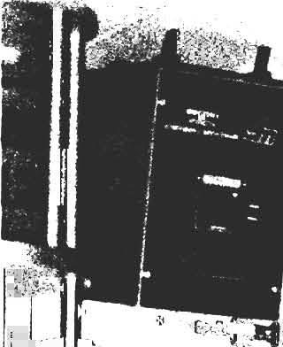
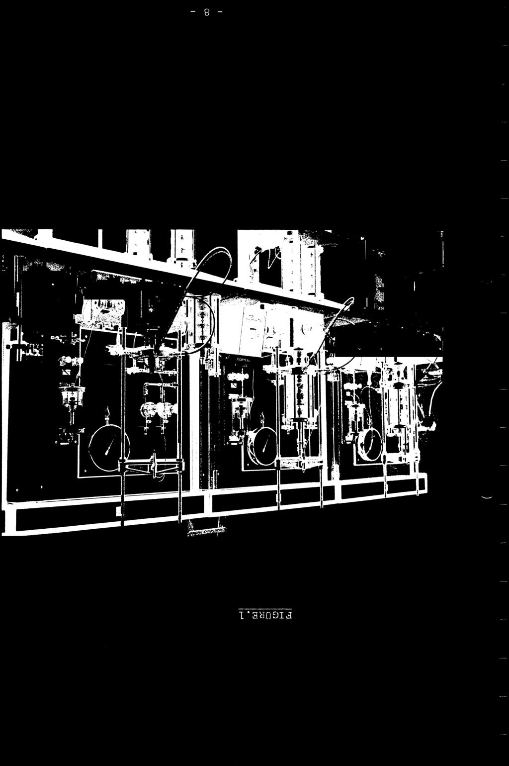
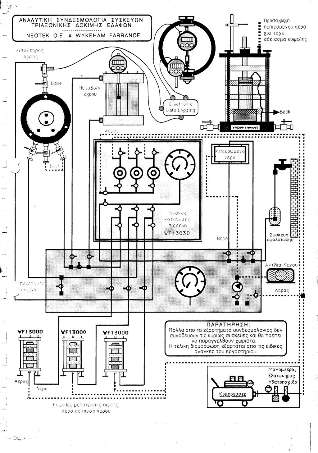
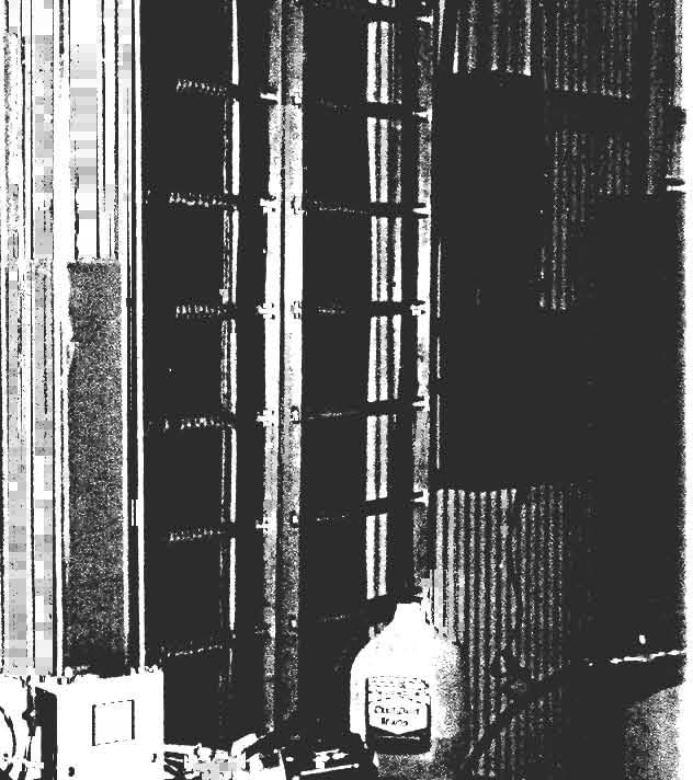
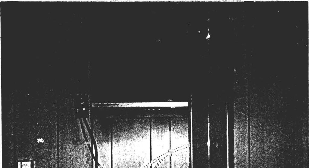
15 Chapter 2 The GeoLab Air pressure-water-vacuum panel In Photo 2.1 the pressure-water-vacuum panel, found in Laboratory of Geomaterials, is shown. As aforementioned, the GeoLab triaxial panel consists of three main pipelines: the air-pressure pipeline, the water pipeline and the vacuum pipeline. The initial design of pipelines actually comes from the air-pressure triaxial panel, designed by Wykeham Farrance. In order to cover the extended needs of the two triaxial apparatus (WF and VJTech) and one biaxial apparatus, the initial WF triaxial panel was extended. The GeoLab triaxial panel consists of the following four main pipelines: 1. Air pressure distribution line (WF Mod.No.13030/SN: ) 2. De-aired water distribution pipeline (WF Mod.No.13030/SN: ) 3. Vacuum distribution line (WF Mod.No.11680/SN: ) 4. CO 2 distribution line In the following sections, brief descriptions of the aforementioned parts will be given. 3
. Figure 2.")
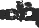
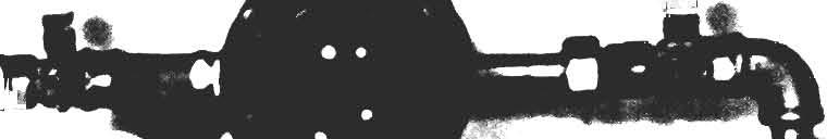
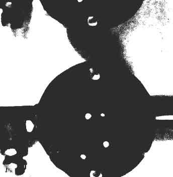
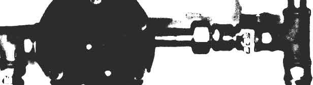
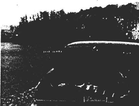
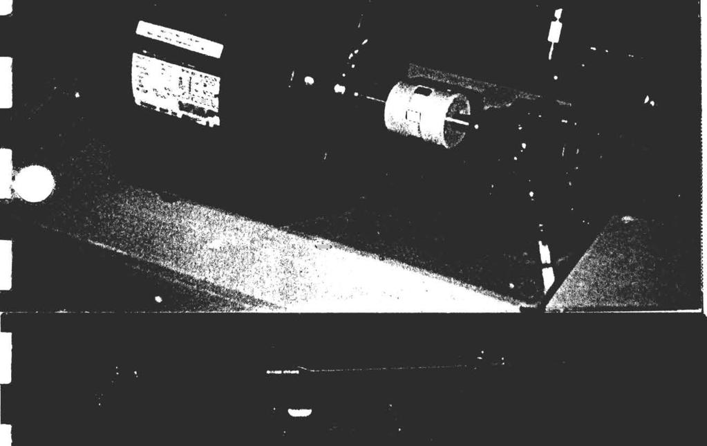
16 The Handbook of Geo-pressure-vacuum panel Figure 2.1: The GeoLab Air pressure-water-vacuum triaxial panel (photo). Figure 2.2: The GeoLab Air pressure-water-vacuum triaxial panel (drawing). 4
17
18
19
20
21
22
23
24


25


26
27


28
29
30
31
32
33
34
35
36
37
38
39
40
41
42
43
44
45
 This is the major pipeline which distributes the air-pressure from the source (air compressor) to pressure regulators, gauges, lines, etc.")
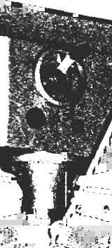
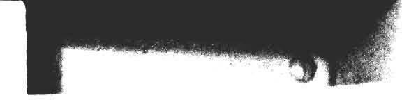
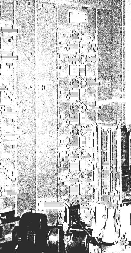
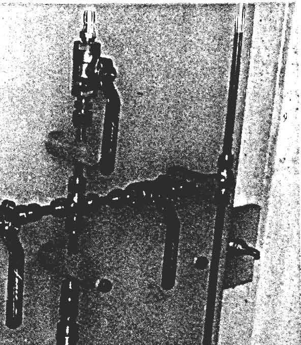
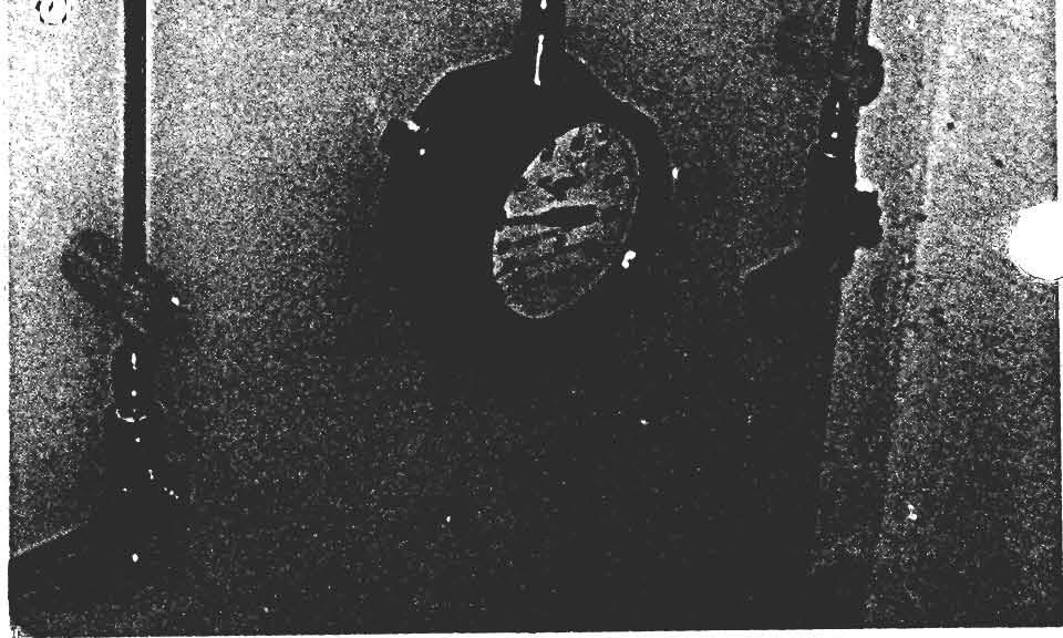
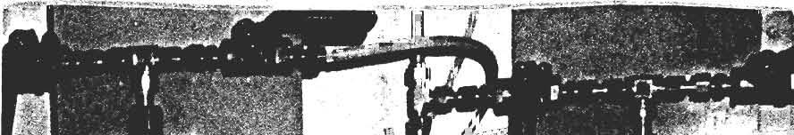
46 The Handbook of Geo-pressure-vacuum panel Figure 2.3: Imperial stepper motors controlling cell (right) and pore (left) pressure (external view). 2.1 Air pressure distribution line (WF Mod.No.:13030/SN: ) This is the major pipeline which distributes the air-pressure from the source (air compressor) to pressure regulators, gauges, lines, etc. In the main pipeline, an analog pressure gauge is mounted on the panel, measuring the air pressure coming from the source (air compressor). This main air pressure line bifurcates in five pressure lines: The stepper motors pressure line, the cell and pore pressure line, the silicon oil tank pressure line and the main pressure line for the triaxial permeability panel (see The handbook of Geotest GeoBiaxial manual ) Imperial stepper motor pressure line This branch supplies with air-pressure coming from the source, the two Imperial stepper motors (see Photo 2.3), controlling the cell and pore pressure. Each stepper motor has one input and one output line. The input line is connected to the stepper motor pressure line, while the output line of each stepper motor is connected to an air distributing block (see Photo 2.5). The cell and pore pressure air distributors supply with regulated air pressure the air-water cells, connected in the cell and pore pressure lines of the triaxial apparatus, respectively. The air-water cells are equipped with a bladder, that is an elastic membrane, which separates the de-aired water from the pressurised air. 5
47
48
49
50
51
")

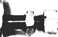
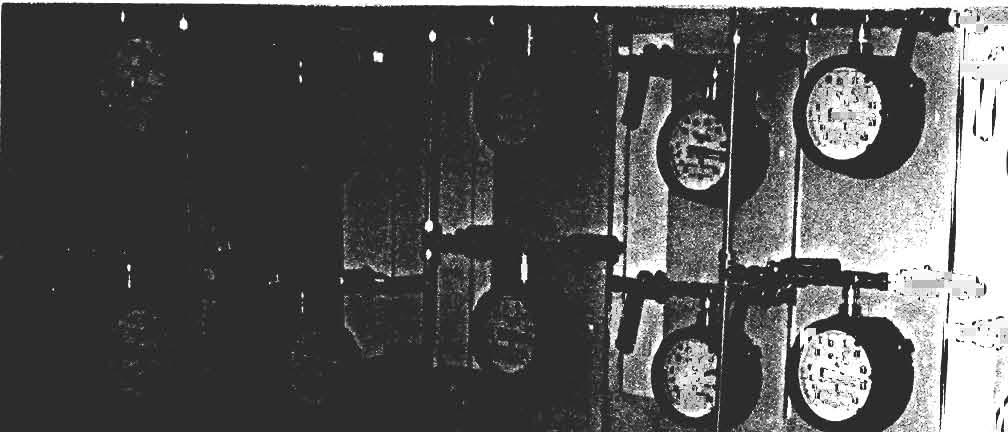
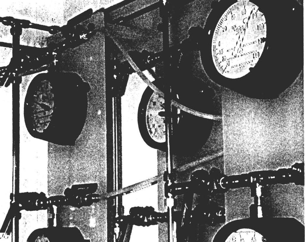
52 The Handbook of Geo-pressure-vacuum panel Figure 2.4: Imperial stepper motors controlling cell (right) and pore (left) pressure (internal view). Figure 2.5: Air distributing blocks of Imperial stepper motors. 6
 and pore (left) pressure line. 2.1.")
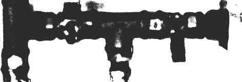
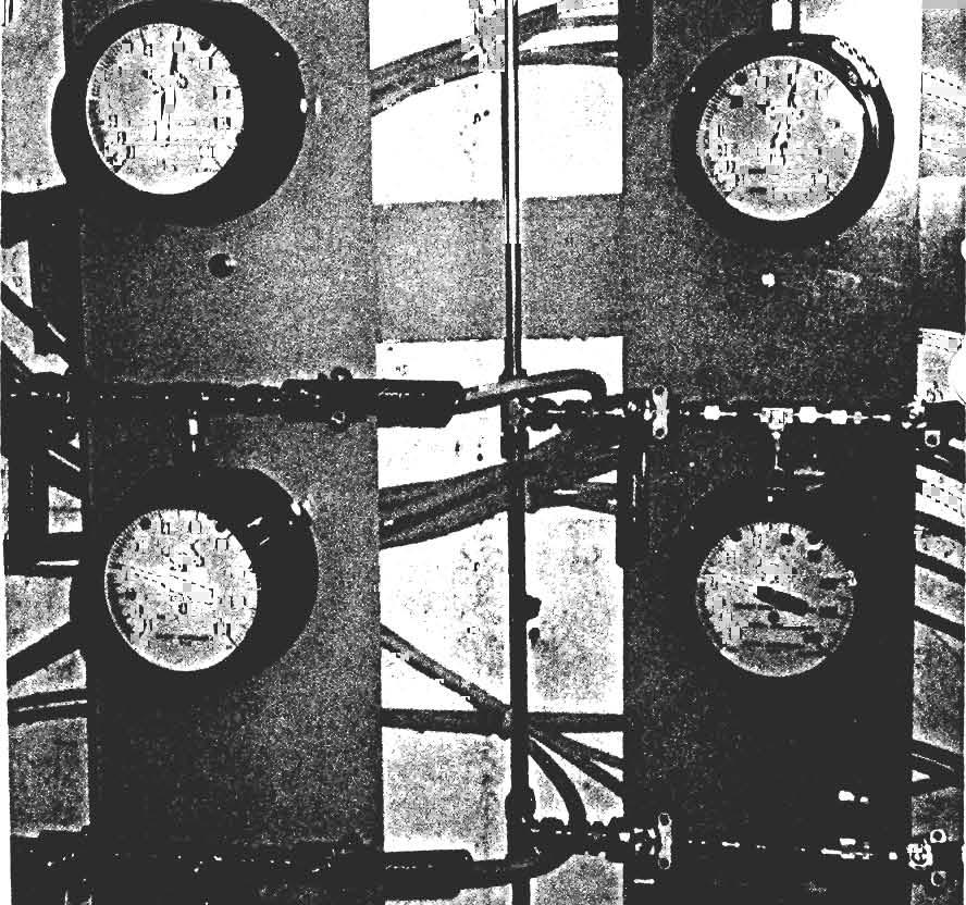
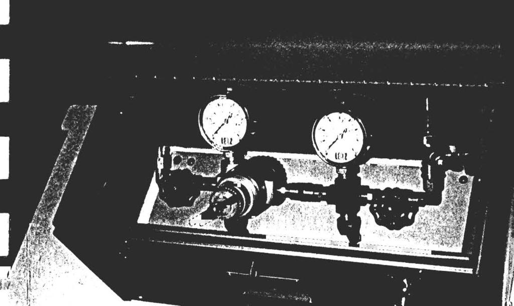
53 The Handbook of Geo-pressure-vacuum panel Figure 2.6: WF12250 air pressure regulators for cell (right) and pore (left) pressure line WF12250 air pressure regulators for cell and pore pressure line This branch almost serves as the previous one, but for mechanical air pressure regulation. Two Wykeham Farrance pressure regulators (WF12250), which are connected to the main air pressure pipeline in parallel, regulate the air pressure. The first one (seen from the right) controls the cell pressure, while the second one, the pore pressure. Both outputs of the pressure regulators are connected to the air-water cells, thus allowing for manual control and regulation of the air pressure WF12250 air pressure regulator for silicon oil tank pressure line The third and last (as seen from the right) air pressure regulator is a WF12250 air pressure controller, whose output is connected to the silicon oil tank. This is the reservoir of the silicon oil used for the biaxial apparatus. The biaxial cell is filled with silicon oil, stored in the tank. Due to its viscosity, air pressure is used to press the oil in its tank and fill the cell. 7


54 The Handbook of Geo-pressure-vacuum panel Figure 2.7: WF12250 air pressure regulator for silicon oil tank pressure line. Figure 2.8: Silicon oil tank for biaxial apparatus. 8
. 2.1.4 Triaxial permeability panel pressure line The last connection to the main air pressure pipeline is the one supplying air pressure to the triaxial permeability panel.")
55 The Handbook of Geo-pressure-vacuum panel Figure 2.9: De-aired water distribution pipeline (WF Mod.No.13030/SN: ) Triaxial permeability panel pressure line The last connection to the main air pressure pipeline is the one supplying air pressure to the triaxial permeability panel. The triaxial permeability panel (for more details see Chapter 5 of The Handbook of the Geotest Geobiaxial apparatus ). 2.2 De-aired water distribution pipeline (WF Mod.No.13030/SN: ) This is the main water pipeline, which supplies with de-aired water the cell and pore pressure lines of the two triaxial and one biaxial apparatus. The de-aired water pipeline is found in the lower part of the GeoLab triaxial panel, and bifurcates in seven main branches. The first one (seen from the right) is connected to the main water source. Just beneath there is a second supply, for de-stilled water. Moreover, three water pipelines are connected to the main pipeline, which serve as distributors to the cell and water pressure air-water cells and to the triaxial permeability panel (biaxial apparatus). The last two branches are connected to the de-airator and to the de-airing tank, mounted just upon the GeoLab triaxial panel The NOLD de-aerator This is the device used to de-air water. De-aired water is used when performing drained or undrained tests in triaxial and biaxial experiments. The use of de-aired water mainly stems from the fact that the WF type au- 9


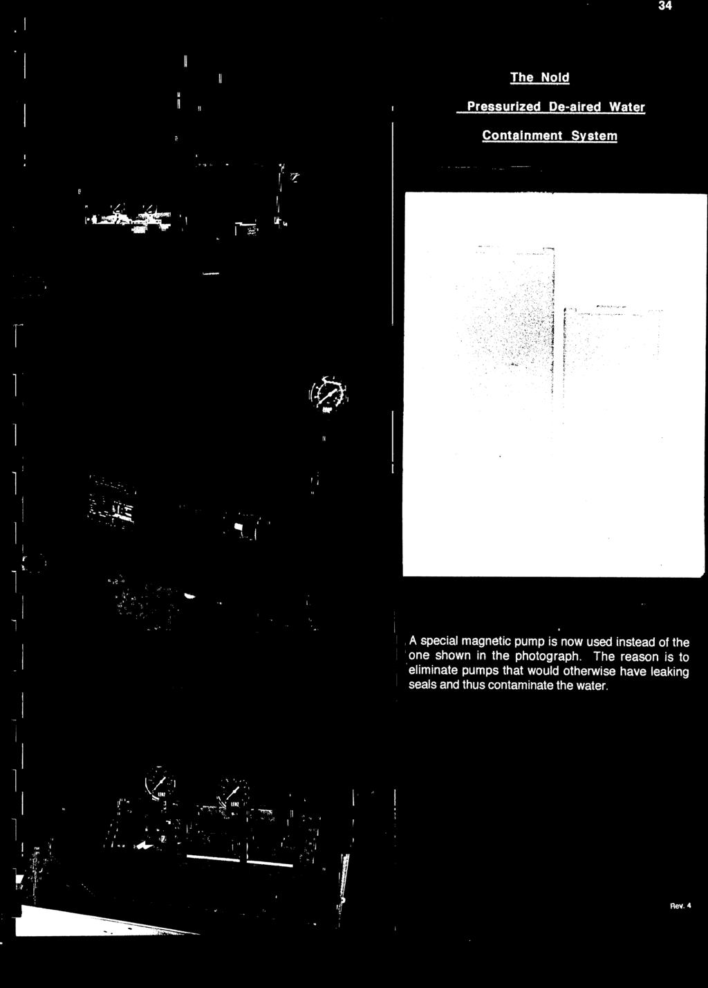
56 The Handbook of Geo-pressure-vacuum panel Figure 2.10: The NOLD de-aerator. Figure 2.11: The NOLD de-aerator in Laboratory of Geomaterials. tomatic volume change apparatus used in the Laboratory of Geomaterials measures the volume of water expelled or sucked by the specimen during the consolidation of drained phase. Any trapped air in the system of pipes or apparatus will inevitably lead to limited accuracy, concerning the volume change of the specimen, due to the fact that air is much more compressible to de-aired water. For this reason, a NOLD de-aerator has been installed in the water pipeline of the Geolab triaxial panel. This device is described in detail in the following pages, where its technical reference is given. 10
57
58
59
60
61
62
63
64
65
66
67
68
69
70
71
72
73

74

75
76
77
78
79
80
81
82
83
84
85
86
87
88
89
90
91
92
93
94
95
96


97
98
99
100


101

102 The Handbook of Geo-pressure-vacuum panel Figure 2.12: The WF11670/WF11680 perspex de-airing tank mounted upon panel The WF11670/WF11680 perspex de-airing tank mounted upon panel This is the tank where de-aired water is stored, after having in de-aired in the NOLD de-aerator. It is made of perspex mounted upon the panel. The tank has three inlets/outlets which are namely: The water inlet, situated at the top comprising en elbow joint connected to a spray nozzle. The vacuum inlet, which provides for connection with either a vacuum jet or vacuum pump. The de-aired water outlet, which operates an outflow under gravity. The tank is deliberately mounted upon the panel, so as to use the gravity for filling the two triaxial cells, the two air-water cells (cell and pore pressure) and allow for saturation of the specimen. In the following, technical specifications of the WF11670/11680 de-airing tank are given in detail. 11


103


104


105


106
107


108
109
110


111
112
113

114
115
116
117
118
119
120
121
122


123
124


125
126


127
128
129
130

131 Model 2100 Nold DeAerator Applications The Model 2100 Nold DeAerator is used in The preparation of deaired, bubble-free, water or glycol solutions (antifreeze), for use in hydraulic settlement systems, twin-tube hydraulic piezometers, and manometer-type water-level monitoring systems The preparation of deaired water for use in soil testing laboratories, triaxial tests, saturation and permeability tests The degassing of hydraulic oils Numerous other nongeotechnical applications such as biological research, food and chemical production, ultrasound imaging, etc. Model 2100 Nold DeAerator shown degassing a liquid (6 liter capacity pictured). Operating Principle The Nold DeAerator is designed to quickly remove dissolved gasses from liquids without the application of heat. It was originally developed for geotechnical applications to allow the preparation of de-aired water for use in hydraulic twin-tube piezometers and hydraulic settlement systems, where the presence of air bubbles in the connecting tubing would give rise to measurement errors. The degassing is accomplished by means of cavitation and nucleation. Cavitation, an ultra-high vacuum, is produced behind the blades of a rotating impeller. The violent agitation so produced breaks up the liquid into a fine mist-like spray of particles (nucleation), from which the dissolved gasses can easily escape. Centrifugal forces hurl the released gasses (air, H 2 S, SO 2, methane, radon, etc.) outwards where they bubble up to an evacuated space above the liquid surface. From there, the gasses are drawn off through a vacuum tube. Geotechnical Instrumentation
 produce de-aired water with a purity of less than 1 ppm dissolved air without the need for application of heat.")
 for the DeAerator to be effective. Belt-driven, two-stage, oilfilled vacuum pumps of 25 liter per minute capacity are preferred.")
132 Model 2100 (8 liter capacity pictured). Typical system components include (from left to right) a storage tank, the Model 2100, a moisture trap, liquid supply and vacuum pump. Advantages and Limitations The Nold DeAerator can quickly (within 3 to 5 minutes) produce de-aired water with a purity of less than 1 ppm dissolved air without the need for application of heat. The Nold DeAerator can be used with all water and glycol mixtures and with hydraulic oils. Liquids which will attack acrylic plastics (such as those containing alcohol), should be avoided. Vacuums must exceed 29.5 inches Hg (12 Torr) for the DeAerator to be effective. Belt-driven, two-stage, oilfilled vacuum pumps of 25 liter per minute capacity are preferred. Where the water aspirator is used, the water pressure must exceed 65 psi (450 kpa) and approximately 12 liters of water will be needed. The water aspirator provided has a 3/8 NPT male connector, which must be adapted to. System Components The Nold DeAerator consists of a sealed acrylic chamber which can be evacuated using either a vacuum pump (not supplied) or a water aspirator supplied with the equipment. The vacuum is used to draw liquid into the chamber through an intake valve. At the base of the chamber is a multi-bladed impeller, which is connected via a magnetic clutch to an electric motor. Energizing the motor rotates the impeller producing cavitation and nucleation. Wetted parts are made from acrylic, polypropylene, epoxy plastics, Buna-N O-rings, stainless steel, brass, and tubing of PVC and latex rubber. Accessories Storage tanks are available for the storage of de-aired liquids. These tanks are identical to the expansion tanks used in heating systems. They contain a rolling rubber membrane that separates one end of the tank from the other, allowing the tank to be filled and emptied without the de-aired liquid coming into contact with the air. Technical Specifications Standard Capacities 6, 8 liters Degassing Purity 0.6 ppm Vacuum Requirements 750 mm Hg, (12 Torr), or better Power Supply 120 V 60 Hz or 240 V 50 Hz Power Consumption 14 watts L W H (6 liter) mm (8 liter) mm Shipping Weight 9 kg The World Leader in Vibrating Wire Technology TM Geokon, Incorporated 48 Spencer Street Lebanon, NH USA Geokon maintains an ongoing policy of design review and reserves the right to amend products and specifications without notice geokon@geokon.com Geokon, Incorporated. All Rights Reserved Doc. Rev. A, 06/04


133 The Handbook of Geo-pressure-vacuum panel Figure 2.13: The WF11670/WF11680 perspex de-airing tank mounted upon panel in Laboratory of Geomaterials (1). Figure 2.14: The WF11670/WF11680 perspex de-airing tank mounted upon panel in Laboratory of Geomaterials (2). 12
134
135
136
137

138 NEOTEK Measuring & Testing Systems Yπ' οψιν κ. ΓΕΩΡΓΟΠΟΥΛΟΣ ΙΩΑΝ-ΟΡΕΣΤ. E. M. ΠOΛYTEXNEIO ΣEMΦE TOMEAΣ MHXANIKHΣ THΛ FAX ΠPOΣΦOPA Nο: Σεπ 2004 ΘEMA ΕΞΑΜΕΝΗ ΑΠΑΕΡΩΜΕΝΟΥ ΝΕΡΟΥ HP. ΠOΛYTEXNEIOY 5, ZΩΓPAΦOY-AΘHNA ΣXETIKA αα ΠOΣ ΠEPIΓPAΦH MONA A ΣYNOΛO Panel Mounted De-Airing Tank Manufactured from Perspex Fitted with inlet spray Γενικοι Oροι: ΣYNOΛO Xρονος Παραδοσης: ηµερες απο ληψεως της παραγγελιας, εκτος απο περιπτωσεις ανωτερας βιας. Tοπος Παραδοσης: AΘHNA ΣYNOΛO ΦΠA 18% Προελευση: AΓΓΛIA Πληρωµη: 0 % Προκαταβολη µε την παραγγελια ΣYNOΛO ΕΥΡΩ % τοις µετρητοίς εντός 30 ηµερών από την παράδοση Iσοτιµία σε PAXMEΣ µε ΦΠA Eγκατασταση: H παραδοση σε λειτουργια θα γινει ΩPEAN απο την εταιρια µας. Iσχυς: 30 ηµερες Eχουµε την ευχαριστηση να σας προσφερουµε τα ακολουθα ειδη που πιστευουµε οτι καλυπτουν τις απαιτησεις σας: Kρατησεις Κρατήσεις δεν περιλαµβάνονται και καµία κράτηση δεν θα γίνει αποδεκτή αν δεν ενηµερωθούµε. 1. Oι παραγγελιες επιβεβαιωνονται εγγραφως 2. Tα ειδη θα πρεπει να αποθηκευθουν ασφαλως µεχρι την παραλαβη των και να παραληφθουν εντος 10 ηµερων. 3. Oι τιµες ισχυουν για το συνολο των προσφεροµενων ανα ειδος µοναδων. Mερικος επιµερισµος µονον κατοπιν συµφωνιας. 4. Tα ειδη συνηθως καλυπτονται απο εγγυηση καλης λειτουργιας 12 µηνων απο την παραδοση. Aναλυτικοι οροι Eγγυησης διατιθενται απο την Eταιρια µας. 5. Oι όροι πληρωµής ισχύουν και για την παραγγελία, εκτός αν δηλωθεί διαφορετικά. 6. Tα είδη παραµένουν στην κυριότητά µας µέχρι τελικής εξόφλησης. E10.01,1 Προµηθευτης: WYKEHAM FARRANCE ENG., LTD. - UK Eιµαστε στη διαθεσή σας για οποιαδηποτε συµπληρωµατικη πληροφορια ή διευκρινιση χρειαστειτε και σας ευχαριστουµε για το ενδιαφερον σας στα προϊοντα µας. NEOTEK O.E. Π.Ξύστρης & Σια Eλ. Bενιζέλου 105 N. Σµύρνη 17122, AΘHNA τηλ: & φαξ: Παν. Nικολακόπουλος

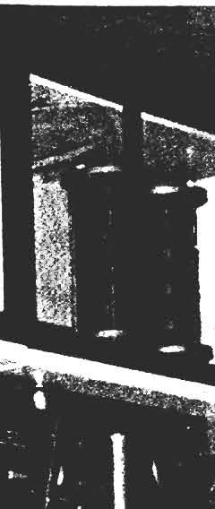
139 The Handbook of Geo-pressure-vacuum panel Figure 2.15: The Imperial constant strain rate pump The Imperial constant strain rate pump This is a portable constant strain rate pump. It has a maximum capacity of 2MPa pressure and is mounted on the air pressure/water/vacuum panel. The pump has to openings: One for filling the chamber of the pump with de-aired water (inlet) and the other to push the de-aired water out of the chamber (outlet). The pump is supplied with de-aired water from the third branch of the main de-aired water pipeline, while its outlet is connected to a distribution block, mounted on the panel. In this way, the one outlet of the pump is split into three, thus supplying with high pressure both triaxial and biaxial apparatus. 2.3 Vacuum distribution line (WF Mod.No.11680/ SN: ) The vacuum line consists of two main parts: The first part is directly connected to the rotary vacuum pump, while the second one, is connected to a Nullmatic pressure/vacuum regulator. An analog vacuum gauge is mounted to the first part of the vacuum pipeline, measuring the vacuum supply from the pump. Both parts of the vacuum pipeline are separated by an on-off valve. Three outlets of the part of the vacuum pipeline that is connected to the pump, are used to supply vacuum to the NOLD de-airator, to the WF11670/WF11680 perspex de-airing tank (vacuum inlet) and to the triaxial and biaxial mold, when forming a sand specimen. The Nullmatic pressure/vacuum regulator allows for regulation of the vacuum, by mixing compressed air with vacuum. The regulator has two inlets, one for vacuum and another for pressure. By adjusting the pressure with its knob key, 13

140 The Handbook of Geo-pressure-vacuum panel Figure 2.16: Vacuum distribution line (WF Mod.No.11680/SN: ). the outlet of the controller is regulated vacuum from -1.0 atm to 0.0atm. The outlet of the regulator is connected to the second part of the vacuum pipeline. Three branches supply with regulated vacuum the triaxial permeability panel and the pore pressure lines in the two triaxial and one biaxial apparatus. 14
141
142
143
144
145
146
147
148
149
150


 Operating temperature 0 C 50 C PNEUMATIC DATA Inlet pressure")
151 6 N S E R I E S Catalogue 2001 Pressure regulator Series N Ports G1/8, G1/4 Nipple type F. R. L. The Series N pressure regulator is available with G1/4 and G1/8 ports. Its design incorporates a self relieving diaphragm so as to allow decremental adjustments. This compact regulator may be mounted directly on pipes or onto a console. GENERAL DATA Construction diaphragm type - nipple type Materials brass, nylon, NBR Threaded ports G1/8 - G1/4 Weight Kg Pressure gauge ports G1/8 Type of mounting in-line or console (in any position) Operating temperature 0 C 50 C PNEUMATIC DATA Inlet pressure Outlet pressure Nominal flow Secondary pressure releiving 0 16 bar bar see graph standard The company reserves the right to vary models and dimensions without notice. These products are designed for industrial applications and are not suitable for sale to the general public.

 1 = 0 4 DESIGN TYPE 0 = self-relieving 1 = non-relieving F. R. L.")


152 Catalogue 2001 S E R I E S N 6 CODING OF REGULATORS N R00 N = SERIES SIZE 12 PORTS 08 = G1/8 04 = G1/4 NOTE : in the place of Mod. N204-R00 use Mod. M004-R00 (page ) R = REGULATOR OPERATING PRESSURE 0 = (standard) 1 = 0 4 DESIGN TYPE 0 = self-relieving 1 = non-relieving F. R. L. FLOW DIAGRAMS N1208-R00 N1204-R00 Pressure regulator, Series N DIMENSIONS Mod. A B C F G I L M N R S U N1208-R x G1/8 N1204-R x G1/4 The company reserves the right to vary models and dimensions without notice. These products are designed for industrial applications and are not suitable for sale to the general public

153 Regulators Models 40, 41, and 42 Precision Pressure Regulators Introduction Features & Benefits Multi-stage, low-droop precision regulators maintain constant output over wide changes in flow and supply pressure Epoxy powder coat paint delivers improved corrosion resistance Wide selection of regulated pressures [1" to 450 psi] affords application versatility Patented Nullmatic pressure regulation system provides reliable maintenance-free operation Description The Models 40, 41, and 42 Precision Pressure Regulators control air pressures in applications where precise and dependable regulation is required, such as pneumatic instrument circuits, test stands, production checking fixtures, and industrial air gages. As such, they are suitable for deadend service, and flows up to a maximum of 110 scfm. A unique, two-stage piloted design provides outstanding accuracy. Rugged construction with no links, levers, pivots, or other friction-producing members ensures reliable, maintenance-free operation. These features allow a regulator to maintain constant output pressure, regardless of even the widest changes in flow or supply pressures. In fact, a regulator using a Model 40, 41, or 42 is practically a self-contained pressure controller operating its supplyplunger valve via a built-in, high-gain pneumatic amplifier. A fine-turn, precision screw is used to manually load the range spring, which sets the regulated pressure. When the adjusting knob is turned clockwise, the increased spring force is exerted on the top diaphragm assembly, decreasing the nozzle clearance and increasing the pilot pressure. Because the source for pilot pressure is supply air flowing to the pilot pressure chamber through the restriction screw, the increased pilot pressure forces the exhaust diaphragm assembly downward. This action closes the exhaust port, and contacts and moves the valve plunger, which opens the supply port. This increases the regulated output, which also feeds back to the top diaphragm assembly. The regulator locks-up or throttles at the new output value when the feedback force of the top diaphragm assembly equals the range spring force. A safety release valve is incorporated in the top diaphragm assembly of several models. It operates if the regulated pressure increases 3 tnú psig more than the set pressure and exhausts air through the atmospheric vent in the top housing. Overpressure causes the diaphragm to move upward, which opens the safety release valve. Specifications Resolution Adjustment Better than 0.03% of regulated output Supply Pressure Maximum & recommended pressures are listed on page 220 Minimum: 5 psig above regulated output Supply Pressure Effect Nominal ratio of change in regulated pressure for a change in supply 1:150 for Model 40 and 42 1:100 for Model 41 Ambient Temperature Limits -40 to 180ºF (-40 to 80ºC) Ambient Temperature Effect Approximately 1% of set pressure with standard range spring; and approximately 0.1% with Isothermal spring for 50 F (27ºC) temperature change Knob Adjustment Model 40 & 42: Nominal 10% of full range for one complete turn Model 41: Nominal 15% of full range for one complete turn Droop Effect See Graph 1 Maximum Air Flow See Graph
154 Regulators Models 40, 41, and 42 Precision Pressure Regulators Technical data 7 Air Consumption See Graph 3 Drift Effect See Graph 4 Exhaust-Flow Rate (at 25-psig setting) Pressure rise of 0.25 psig will result from flow of: Model 40: 1.5 scfm Model 41: 2.4 scfm Model 42: 1.7 scfm Maximum Flow Capacity See Graph on page 219 Standard Mounting In-line pipe or flush panel up to 1/4" thick (bushing for 3/4" thick panel is optional) Connections: (supply and outlet) Model 40: 1/4" NPT Model 41: 1/8" NPT Model 42: 1/2" NPT Materials of Construction (and materials in contact with regulated media) Brass, stainless steel, Neoprene, aluminum, and zinc Accessories P/N Mounting Bracket for surface mounting (Model 40 and Model 42) P/N Mounting Bracket for surface mounting (Model 41) P/N Locknut 7.2 Options Air Loading Provision for supplementary air loading (100 psig max) in addition to spring loading Model 40, 42: 1/4" NPT Model 41: 1/8" NPT Model 40-2: Not available Add [A] into the model number. Example: 40A15 Tapped Exhaust Provision for piping exhaust flow away from the regulator Model 40, 42: 1/8" NPT Model 41: Not available Add [E] into the model number. Example: 40E15 Isothermal Range Spring Reduces ambient temperature effect from approximately 1% of set pressure to approximately 0.1% for a 50 F [27 C] temperature range Model 40: 15, 30, 50, & 100 psig ranges Model 41: Not available Model 42: 30, 50, & 100 psig ranges Add (M9) to the Moore 40 number. Add (M26) to the Moore 42 model number. Example: 40-15M9, 42-30M26 Deletion of Safety Release Valve (SRV) The SRV increases exhaust flow capacity when the regulator must exhaust large flows. Deletion of the SRV will improve drift characteristics (see Graph 4). The SRV is not available with the Moore 41. It is standard with: Model 40: 2, 7, 15, 30, 50 & H50 pressure ranges Model 42: 15, 30, 50, H30, & H50 pressure ranges To delete the SRV, add an [X] into the model number. Example: 40X15 Slotted Adjusting Screw Available for all models. This option provides for screwdriver adjustment of the regulator and includes a locknut. Model 40: Add (M3) after the model number Model 41: Add (M3) after the model number Model 41: Add (M20) after the model number Example: 40-15(M3) Locknut with Longer Adjusting Screw Available for all models. This option prevents inadvertent regulator adjustment. Model 40: Add (M13) after the model number. (Note: The Model 40-2 is standard with the lock nut.) Model 41: Add (M5) after the model number or order accessory P/N Model 42: Add (M3) after the model number Example: 40-15(M3) Bushings for mounting on panels up to 3/4" thick (Standard maximum is 1/4" thick). Model 40: Add (M41) after the model number Model 41: Not available Model 42: Add (M14) after the model number Example: 40-15(M41)
155 Regulators Models 40, 41, and 42 Precision Pressure Regulators Technical data Graph 1 Droop Effect Test Procedure: Each 30-psig-range regulator was adjusted to 25 psig with 100 psig supply and no flow. Flow was increased to maximum capacity. All regulated pressure readings were taken at gauge connection in the body of the regulator. Note: For performance curves on Model 40-2 and 40-7, request drawing # and , respectively
156 Regulators Models 40, 41, and 42 Precision Pressure Regulators Technical data Graph 2 Maximum Air Flow, SCFM Delivered * Supply pressure for other models will be determined by multiplying the pressure(s) above by the flow values shown below: Model Value Model 40H 4.5 Model 42 4 Model 42H 14 Graph 3 Air Consumption Graph 4 Drift Effect 7 Test Procedure: Regulators were set at 20 psig output with 100 psig air supply. Supply was turned off for one week, after which supply was turned on at time 0. The Nullmatic regulator bleeds only the amount of air that passes through the pilot nozzle when there is no demand for output flow. The exhaust port starts to close as soon as the flow of regulated air is increased to the output, and it closes completely before the pilotplunger valve opens. Full pilot flow is then delivered to the output. 7.4
157 Regulators Models 40, 41, and 42 Precision Pressure Regulators Technical data Model Selection Supply Pressure Gauge (Opt.) psig Dia. Inches Model Range Pipe Panel Standard No. psig 3 Recommended Maximum Mtg. Mtg. Modifications (1-50"H 2 O) /2 3-1/2 E & X 40-7 (6-200"H 2 O) /2 3-1/2 A, E & X /2 3-1/2 A, E & X /2 3-1/2 A, E & X / /2 4 H, A, E & X /2 3-1/2 H, A & E /2 3-1/2 A & E /2 3-1/2 A & E /2 3-1/2 A & E /2 A 41N / /2 A /2 4 A /2 A / /2 3-1/2 A, E & X /2 3-1/2 H, A, E & X / /2 4 H, A, E & X /2 3-1/2 H, A & E /2 3-1/2 A & E Standard Modifications H - High flow capacity. A - With pressure-tight top housing, containing 1/4" NPT connection for supplementary air loading. E - With 1/8" NPT connection to collect exhaust when used with gases other than air. X - Without safety release. 7 1) Includes locknut on adjusting stem (optional for all other models). 2) For use with Model 65 Square-Root Extractor to maintain minimum 3 psig output. 3) At recommended supply pressure. 4) With 0-60 psig dial range. 5) For pipe-mounting, 2" dia. gauge (0-30 psig) is available. 7.5
158 Regulators Models 40, 41, and 42 Precision Pressure Regulators Dimensional drawings Mounting Dimensions Model 40 Pipe or Bracket-Mounted with Gauge Panel-Mounting with Gauge Model 41 7 Model
 in a tank or bottle.")

159 The Handbook of Geo-pressure-vacuum panel Figure 2.17: CO 2 high pressure bottle. Figure 2.18: Detendeur HBS reducing high CO 2 pressure from bottle. 2.4 CO 2 distribution line CO 2 under pressure is usually used in the saturation phase in drained and undrained tests. CO 2 is much more dissolvable that air in water, thus allows for larger saturation degrees. CO 2 is stored under high pressure (300bar) in a tank or bottle. A pressure regulator (detendeur HBS) (see Photo 2.18) is installed on the bottle to reduce the output pressure in the range (0-10bar). The outlet of the pressure regulator is connected to a distribution block on the air pressure-water-vacuum panel. The distribution block has, apart from the inlet CO 2 on-off valve, three CO 2 regulated outlets. A Camozzi type Series C regulator (0-4bars) is installed in the distribution block regulating the input CO 2 pressure. 15

160 The Handbook of Geo-pressure-vacuum panel Figure 2.19: Detendeur HBS installation diagram. Figure 2.20: CO 2 distribution block. 16
 Détendeur HBS 240-1-2 Détendeur HBS 240-0,1-0,5 P.")
.")
161 TM DETENDEURS HP HBS Détendeurs pour bouteille - haute précision A membrane ou soufflet - conservation de la pureté du gaz Double détente - adaptés pour tous gaz purs En laiton chromé P. de sortie (mbar) Détendeur HBS Détendeur HBS 240-0,1-0,5 P. d'entrée : 3 bar 100 Q max 1350l/h 50 Q max 800l/h Débit en azote (l/h) HBS 240-0,1-0,5 Compatibilité avec les gaz Les détendeurs HBS sont conçus pour la mise en œuvre des gaz purs à l exception des gaz corrosifs et de l acétylène (pour plus de précisions se reporter au guide de choix des détendeurs du catalogue matériels de mise en œuvre des gaz purs). Domaines d application Les détendeurs HBS sont destinés aux laboratoires de contrôle et d analyse, exigeant une régulation de pression très précise des gaz purs. Caractéristiques principales Modèle Pression maximale Pression de sortie Débit nominal* d entrée (bar) réglable de/à (bar) en azote (m 3 /h) HBS 240-0,1-0, ,01 à 0,1 0,5 HBS ,05 à 1 2 HBS , ,1 à 3 2,5 HBS ,5 à 8 3 Taux de fuite intérieur/extérieur 3x 10⁻⁷ mbar.l/s d hélium. Température de fonctionnement de -20 C à +50 C Coefficients R et I 10 % et f 0,5 %.* Mise sous vide possible (sauf HBS 240-0,1-0,5). Caractéristiques de construction Corps en laiton chromé. Sièges 1 ère détente en PTFCE, 2 ème détente en EPDM. Clapets en laiton. Membrane en acier inoxydable (HBS 240-0,1-0,5). Soufflet en bronze (HBS 240-1, 3 et 8). * voir Détendeurs dans Informations Générales. Filtre d entrée en acier inoxydable. Soupape collectable en laiton, corps en acier inoxydable. Joints en EPDM. Homologation oxygène* : AIR LIQUIDE CTE n 97/JPS/139 * voir Sécurité dans Informations Générales. Les détendeurs HBS forment, avec un certain nombre d accessoires, le système HBS. Voir page suivante. P. d'entrée : 1 = 200 bar 2 = 21 bar P. d'entrée : 1 = 200 bar 2 = 21 bar P. d'entrée : 1 = 200 bar 2 = 21 bar P. de sortie (bar) 1 0, ,5 1 1,5 2 2,4 Débit en azote (m 3 /h) P. de sortie (bar) ,5 1 1,5 2 2,5 3 Débit en azote (m 3 /h) P. de sortie (bar) Débit en azote (m 3 /h) HBS HBS ,5 HBS Pour commander, consulter les références au verso
162 TM Les détendeurs présentés dans le tableau ci-dessous sont livrés équipés de manomètres de pression d entrée et de sortie et d une soupape collectable. Sauf indication contraire, ils sont fournis avec les raccords d entrée et de sortie, à monter. Pour commander toujours préciser : la référence choisie, la nature du gaz, la pression de sortie souhaitée. Référence Désignation HBS 240-0,1-0,5 bouteille Sans raccords d entrée ni de sortie Avec raccord d entrée pour bouteille et kit de sortie n Raccord d entrée type C Raccord d entrée type E Raccord d entrée type F Raccord d entrée type G Raccord d entrée type B Raccord d entrée type L Raccord d entrée type M Raccord d entrée type N HBS bouteille Sans raccords d entrée ni de sortie Avec raccord d entrée pour bouteille et kit de sortie n Raccord d entrée type C Raccord d entrée type E Raccord d entrée type F Raccord d entrée type G Raccord d entrée type B Raccord d entrée type L Raccord d entrée type M Raccord d entrée type N Référence Désignation HBS ,5 bouteille Sans raccords d entrée ni de sortie Avec raccord d entrée pour bouteille et kit de sortie n Raccord d entrée type C Raccord d entrée type E Raccord d entrée type F Raccord d entrée type G Raccord d entrée type B Raccord d entrée type L Raccord d entrée type M Raccord d entrée type N HBS bouteille Sans raccords d entrée ni de sortie Avec raccord d entrée pour bouteille et kit de sortie n Raccord d entrée type C Raccord d entrée type E Raccord d entrée type F Raccord d entrée type G Raccord d entrée type B Raccord d entrée type L Raccord d entrée type M Raccord d entrée type N Les raccords d entrée sont différents selon le gaz utilisé et les normes des pays. Ils sont définis dans le chapitre raccords du catalogue. En cas de doute, consultez nos services. Encombrement raccord d entrée détendeur (sans raccord) raccord de sortie voir page 176 HBS 240-0,1-0,5 réf voir page 202 HBS réf HBS ,5 réf HBS réf HBS 240-1, 3 et 8 Hors raccords L : 72 mm H : 104 mm P : 180 mm Ø 1 : 50 mm Poids : 1,4 kg Maintenance Référence Désignation Manomètre mbar pour HBS 240-0,1-0, Manomètre ,5 bar pour HBS Manomètre bar pour HBS , Manomètre bar pour HBS Manomètre bar pour tous HBS Soupape collectable tarée à 16 bar Joints plats, en sachet de 10, pour manomètres Air Liquide se réserve le droit d apporter, sans préavis, toute modification jugée nécessaire aux spécifications ci-dessus. (voir "Informations Générales") Pour plus d'informations, demander la fiche technique correspondant à ces matériels AIR LIQUIDE GAZ INDUSTRIELS SERVICES 9, avenue Descartes - BP Le Plessis Robinson Cedex H L Ø1 P L Orifices Entrée : Ø 16 pas 1,336 S.I. femelle Sortie : G 3/8 femelle cylindrique H Référence Désignation Joints toriques, en sachet de 10, pour raccord d entrée Ø 16 pas 1,336 S.I Joints plats, en sachet de 10, pour orifice de sortie G 3/ Joints toriques, en sachet de 10, pour raccord d entrée type C ou E Joints toriques, en sachet de 10, pour raccord d entrée type B Joints toriques, en sachet de 10, pour raccord d entrée type F, L, M et N Joints coniques, en sachet de 10, pour raccord d entrée type G 130 P Ø1 Fiche technique n FT 1013 HBS 240-0,1-0,5 Hors raccords L : 98 mm H : 135 mm P : 180 mm Ø 1 : 50 mm Poids : 1,8 kg Réf. : Conception - Réalisation A de C - 12/99
163 Chapter 3 The GeoLab air compressor One could name it the main engine of a typical Soil Mechanics Laboratory. Indeed, the air compressor is the unit that supplies with compressed air vital apparatus and parts of a triaxial air pressure/water/vacuum panel. The selection of an air compressor is mainly controlled by two parameters: Its maximum working pressure and its air flow discharge/capacity. The air compressor is housed near the Lab, in a special place, away from the apparatus, for safety reasons. Its maximum air pressure capacity is 12bars with a tank volume reaching 100lt. The minimum and maximum working pressure can be regulated by a knob key. A copper pressure line from the stockhouse to the laboratory is used to connect the main air pressure pipeline of the panel with the air compressor. More information and technical data concerning the air compressor can be found in the following pages. 17


164 The Handbook of Geo-pressure-vacuum panel Figure 3.1: ABAC air compressor. Figure 3.2: Air compressor used in the Laboratory of Geomaterials. 18
165 Chapter 4 The GeoLab vacuum pump As the air compressor serves as the main source of pressurized air for all apparatus, a rotary vacuum pump supplies the main vacuum pipeline with vacuum. The pump may reach a vacuum level as low as -0.9atm, and its capacity is characterised by the air-discharge. Like the air compressor, the vacuum pump is installed in a stockhouse and is connected to the main vacuum pipeline in the panel by a copper pipe. More information and technical data concerning the vacuum pump can be found in the following pages. 19


166 The Handbook of Geo-pressure-vacuum panel Figure 4.1: Pfeiffer vacuum pump. Figure 4.2: Vacuum pump used in the Laboratory of Geomaterials. 20
167
168
169
170
171
172
173
174
175
176
177
178
179
180
181
182
183
184
185
186
187
188
189
190
191
192
193
194
195
196
197
198

199
200 Appendix A Fittings, valves and plastic hoses of panel In the Appendix, technical information concerning fittings, on-off valves, elastic hoses, etc. used in the air pressure-water-vacuum panel is given. 21
201 The Handbook of Geo-pressure-vacuum panel 22
202
203
204
205
206
207


.")


208 Catalogue 2001 Pipe fittings and tubing T, MPL, PNZ Tube od ø4/2, 5/3, 6/4, 8/6, 10/8, 12/10, 14/12, 15/12,5 Connections M5, G1/8, G1/4, G3/8, G1/2 R1/8, R1/4, R3/8, R1/2, R3/4 7 When involved in factory maintenance or plant installation it is often difficult to be cetain which size of fitting will be required. The camozzi pipe fitting range provides a cost effective solution to this problem. The full range includes straight, L-shaped, T-shaped and cross piece male or female couplings and are available in a variety of thread sizes up to G1/2. Material: brass OT58 (nickel-plated) F I T T I N G S The company reserves the right to vary models and dimensions without notice. These products are designed for industrial applications and are not suitable for sale to the general public


209 7 Catalogue 2001 Fittings Mod Fittings Mod F I T T I N G S DIMENSIONS Mod. A H L SW /8 R1/ /4 R1/ /8 R3/ /2 R1/ /4 R3/ DIMENSIONS Mod. A H L SW 2501 M5 M /8 G1/ /4 G1/ /8 G3/ /2 G1/ Fittings Mod Fittings Mod DIMENSIONS Mod. A1 A2 H1 H2 L SW /8-1/4 R1/8 R1/ /8-3/8 R1/8 R3/ /4-3/8 R1/4 R3/ /4-1/2 R1/4 R1/ /8-1/2 R3/8 R1/ /2-3/4 R1/2 R3/ DIMENSIONS Mod. A1 A2 H1 H2 L SW 2511 M5-1/8 M5 G1/ /8-1/4 G1/8 G1/ /8-3/8 G1/8 G3/ /4-3/8 G1/4 G3/ /4-1/2 G1/4 G1/ /8-1/2 G3/8 G1/ The company reserves the right to vary models and dimensions without notice. These products are designed for industrial applications and are not suitable for sale to the general public.


210 Catalogue Fittings Mod Fittings Mod DIMENSIONS Mod. A B H L SW /8-1/8 R1/8 G1/ /8-1/4 R1/8 G1/ /8-3/8 R1/8 G3/ /4-1/4 R1/4 G1/ /4-3/8 R1/4 G3/ /4-1/2 R1/4 G1/ /8-3/8 R3/8 G3/ /8-1/2 R3/8 G1/ /2-1/2 R1/2 G1/ DIMENSIONS Mod. A B H L SW 2521 M5-1/8 M5 G1/ /8-1/8 G1/8 G1/ /8-1/4 G1/8 G1/ /8-3/8 G1/8 G3/ /4-1/4 G1/4 G1/ /4-3/8 G1/4 G3/ /4-1/2 G1/4 G1/ /8-3/8 G3/8 G3/ /8-1/2 G3/8 G1/ /2-1/2 G1/2 G1/ F I T T I N G S Fittings Mod Fittings Mod DIMENSIONS Mod. A B H I L SW /8-16 G1/8 G1/ /8-36 G1/8 G1/ /4-27 G1/4 G1/ /4-43 G1/4 G1/ DIMENSIONS Mod. A B H L SW /4-1/8 R1/4 G1/ /8-1/8 R3/8 G1/ /2-1/8 R1/2 G1/ /8-1/4 R3/8 G1/ /2-1/4 R1/2 G1/ /2-3/8 R1/2 G3/ /4-1/2 R3/4 G1/ The company reserves the right to vary models and dimensions without notice. These products are designed for industrial applications and are not suitable for sale to the general public


211 7 Catalogue 2001 Fittings Mod Fittings Mod F I T T I N G S DIMENSIONS Mod. A B H L SW /8 - M5 G1/8 M /4-1/8 G1/4 G1/ /8-1/8 G3/8 G1/ /2-1/8 G1/2 G1/ /8-1/4 G3/8 G1/ /2-1/4 G1/2 G1/ /2-3/8 G1/2 G3/ DIMENSIONS Mod. B L SW 2543 M5 M /8 G1/ /4 G1/ /8 G3/ /2 G1/ Fittings Mod Fittings Mod DIMENSIONS Mod. B1 B2 L SW 2553 M5-1/8 M5 G1/ /8-1/4 G1/8 G1/ /8-3/8 G1/8 G3/ /8-1/2 G1/8 G1/ /4-3/8 G1/4 G3/ /4-1/2 G1/4 G3/ /8-1/2 G3/8 G1/ DIMENSIONS Mod. A H L SW 2611 M5 M /8 G1/ /4 G1/ /8 G3/ /2 G1/ The company reserves the right to vary models and dimensions without notice. These products are designed for industrial applications and are not suitable for sale to the general public.


212 Catalogue Fittings Mod Fittings Mod DIMENSIONS Mod. A H L SW /4 R3/ DIMENSIONS Mod. B L SW /8 G1/ /4 G1/ /8 G3/ /2 G1/ F I T T I N G S Fittings Mod DIMENSIONS Mod. N A C H I L SW M5 2 M ,5 - M5 4,5 M /8 7 G1/ /4 7 G1/ /8 8 G1/ /8 9 G1/ /4 9 G1/ /8 9 G3/ /4 12 G1/ /8 12 G3/ /2 12 G1/ /8 17 G3/ /2 17 G1/ Fittings Mod DIMENSIONS Mod. A E H SW /8 R1/ /4 R1/ /8 R3/ /2 R1/ The company reserves the right to vary models and dimensions without notice. These products are designed for industrial applications and are not suitable for sale to the general public


213 7 Catalogue 2001 Fittings Mod F I T T I N G S DIMENSIONS Mod. B M SW /8 G1/ /4 G1/ /8 G3/ /2 G1/ Fittings Mod and Mod DIMENSIONS Mod. A B E H M SW 2021 M5 - M5 M5 M , /8-1/8 R1/8 G1/ /4-1/4 R1/4 G1/ /8-3/8 R3/8 G3/ /2-1/2 R1/2 G1/ Fittings Mod DIMENSIONS Mod. A B E H L M SW /8-1/8 R1/8 G1/ /4-1/4 R1/4 G1/ /8-3/8 R3/8 G3/ , /2-1/2 R1/2 G1/ Fittings Mod DIMENSIONS Mod. A B E H M SW /8-1/8 R1/8 G1/ /4-1/4 R1/4 G1/ /8-3/8 R3/8 G3/ /2-1/2 R1/2 G1/ The company reserves the right to vary models and dimensions without notice. These products are designed for industrial applications and are not suitable for sale to the general public.


214 Catalogue Fittings Mod DIMENSIONS Mod. A E H SW /8 R1/ /4 R1/ /8 R3/ /2 R1/ Fittings Mod F I T T I N G S DIMENSIONS Mod. A B E H L M SW /8-1/8 R1/8 G1/ /4-1/4 R1/4 G1/ /8-3/8 R3/8 G3/ , /2-1/2 R1/2 G1/ Fittings Mod DIMENSIONS Mod. A B E H M SW /8-1/8 R1/8 G1/ /4-1/4 R1/4 G1/ /8-3/8 R3/8 G3/ /2-1/2 R1/2 G1/ Fittings Mod DIMENSIONS Mod. B H M SW /8 G1/ /4 G1/ /8 G3/ /2 G1/ The company reserves the right to vary models and dimensions without notice. These products are designed for industrial applications and are not suitable for sale to the general public


215 7 Catalogue 2001 Fittings Mod F I T T I N G S DIMENSIONS Mod. A B H E M SW /8-1/8 R1/8 G1/ /4-1/4 R1/4 G1/ /8-3/8 R3/8 G3/ /2-1/2 R1/2 G1/ Fittings Mod DIMENSIONS Mod. B M M1 SW /8 G1/ /4 G1/ , /8 G3/ /2 G1/ Fittings Mod DIMENSIONS Mod. B H M SW /8 G1/ /4 G1/ /8 G3/ Fittings Mod Assembly possible only with Mod. SCU, SCO, SVU...M5 * assembly required with Mod DIMENSIONS Mod. B M O V W 2023 M5 - M5 M M5 - M6 M /8-1/8 G1/ /4-1/4 G1/ * /8-3/8 G3/ * The company reserves the right to vary models and dimensions without notice. These products are designed for industrial applications and are not suitable for sale to the general public.
 blue. Aluminium F I T T I N G S DIMENSIONS Mod. D/d Operating pressure at 30 C PV 6/4 6/4 25 bar PV 8/6 8/6 25 bar PV 10/8 10/8 25 bar PV 12/10 12/10 25 bar PV 15/12.")

216 Catalogue Fittings Mod DIMENSIONS Mod. B C F L T SW /8 G1/ /4 G1/ /8 G3/ /2 G1/ Tubes Mod. PV... Tubing (PVC reinforced) blue. Aluminium F I T T I N G S DIMENSIONS Mod. D/d Operating pressure at 30 C PV 6/4 6/4 25 bar PV 8/6 8/6 25 bar PV 10/8 10/8 25 bar PV 12/10 12/10 25 bar PV 15/ / bar Tubes Mod. TRN... Tubing (Rilsan) *available on request. DIMENSIONS Mod. D/d Operating pressure at 20 C TRN 4/2 4/2 33 bar TRN 5/3 5/3 25 bar TRN 6/4 6/4 20 bar TRN 8/6 8/6 14 bar TRN 10/8 10/8 11 bar TRN 12/10 12/10 9 bar Natural * Blue * Red * Green * Black * Yellow Tubes Mod. TPE... Tubing (Polyethylene) Plain, Blue. DIMENSIONS Mod. D/d Operating pressure at 20 C TPE 5/3 5/3 12 bar TPE 6/4 6/4 11 bar TPE 8/6 8/6 8 bar TPE 10/8 10/8 7 bar The company reserves the right to vary models and dimensions without notice. These products are designed for industrial applications and are not suitable for sale to the general public


 (tube cutter) 7.")
217 7 Catalogue 2001 Tubes Mod. TSP... Coil (Rilsan) blue (other colours available on request). F I T T I N G S DIMENSIONS Mod. D/d P. a 20 C ø est. L. chiusa L. max. TSP 6/4 6/4 20 bar TSP 8/6 8/6 14 bar TSP 10/8 10/8 11 bar TSP 12/10 12/10 9 bar Tubes clamp Mod. MPL... Tube clamp blue. DIMENSIONS Mod. øtubo L A d P MPL 4 4/ MPL 6 6/ MPL 8 8/ MPL 10 10/ Tubes cutter Mod. PNZ... Mod. PNZ-12 PNZ-25 (tube cutter) (tube cutter) The company reserves the right to vary models and dimensions without notice. These products are designed for industrial applications and are not suitable for sale to the general public.


218 7 Catalogue 2001 Pipe fittings Sprint Connections G1/8, G1/4, G3/8, G1/2 R1/8, R1/4, R3/8, R1/2 F I T T I N G S When involved in factory maintenance or plant installation it is often difficult to be absolutely certain which size of fittings will be required. Pipe fittings provide a cost effective solution to this problem. The full range includes straight, L-shaped, T-shaped and cross piece male or female couplings and are available in a variety of thread sizes up to 1/2. The addition of the Camozzi Sprint sealing ring to 13 different models of pipe fittings eliminates the need to use liquid sealant or tape and saves a considerable amount of time during installation. The Sprint fitting can be connected and disconnected several times. Material: brass OT58 nickel-plated. T. min C T. max C The company reserves the right to vary models and dimensions without notice. These products are designed for industrial applications and are not suitable for sale to the general public.


219 Catalogue Fittings Mod. S DIMENSIONS Mod. A H L SW S2500 1/8 R1/ S2500 1/4 R1/ S2500 3/8 R3/ S2500 1/2 R1/ Fittings Mod. S F I T T I N G S DIMENSIONS Mod. A1 A2 H1 H2 L SW S2510 1/8-1/4 R1/8 R1/ S2510 1/8-3/8 R1/8 R3/ S2510 1/4-3/8 R1/4 R3/ S2510 1/4-1/2 R1/4 R1/ S2510 3/8-1/2 R3/8 R1/ Fittings Mod. S DIMENSIONS Mod. A B H L SW S2520 1/8-1/8 R1/8 G1/ S2520 1/8-1/4 R1/8 G1/ S2520 1/8-3/8 R1/8 G3/ S2520 1/4-1/4 R1/4 G1/ S2520 1/4-3/8 R1/4 G3/ S2520 1/4-1/2 R1/4 G1/ S2520 3/8-3/8 R3/8 G3/ S2520 3/8-1/2 R3/8 G1/ S2520 1/2-1/2 R1/2 G1/ Fittings Mod. S DIMENSIONS Mod. A B H L SW S2530 1/4-1/8 R1/4 G1/ S2530 3/8-1/8 R3/8 G1/ S2530 1/2-1/8 R1/2 G1/ S2530 3/8-1/4 R3/8 G1/ S2530 1/2-1/4 R1/2 G1/ S2530 1/2-3/8 R1/2 G3/ The company reserves the right to vary models and dimensions without notice. These products are designed for industrial applications and are not suitable for sale to the general public


220 7 Catalogue 2001 Fittings Mod Mod. Sprint girevole. F I T T I N G S DIMENSIONS Mod. A B H L SW SW /8-1/8 R1/8 G1/ /4-1/4 R1/4 G1/ /8-3/8 R3/8 G3/ Fittings Mod. S DIMENSIONS Mod. A E H SW S2010 1/8 R1/ S2010 1/4 R1/ S2010 3/8 R3/ S2010 1/2 R1/ Fittings Mod. S DIMENSIONS Mod. A B E H M SW S2020 1/8-1/8 R1/8 G1/ S2020 1/4-1/4 R1/4 G1/ S2020 3/8-3/8 R3/8 G3/ S2020 1/2-1/2 R1/2 G1/ Fittings Mod. S DIMENSIONS Mod. A B H E M SW S2040 1/8-1/8 R1/8 G1/ S2040 1/4-1/4 R1/4 G1/ S2040 3/8-3/8 R3/8 G3/ S2040 1/2-1/2 R1/2 G1/ The company reserves the right to vary models and dimensions without notice. These products are designed for industrial applications and are not suitable for sale to the general public.


221 Catalogue Fittings Mod. S DIMENSIONS Mod. A B E H L M SW S2050 1/8-1/8 R1/8 G1/ S2050 1/4-1/4 R1/4 G1/ S2050 3/8-3/8 R3/8 G3/ , S2050 1/2-1/2 R1/2 G1/ F I T T I N G S Fittings Mod. S DIMENSIONS Mod. A B E H M SW S2060 1/8-1/8 R1/8 G1/ S2060 1/4-1/4 R1/4 G1/ S2060 3/8-3/8 R3/8 G3/ S2060 1/2-1/2 R1/2 G1/ Fittings Mod. S DIMENSIONS Mod. A B E H L M SW S2070 1/8-1/8 R1/8 G1/ S2070 1/4-1/4 R1/4 G1/ S2070 3/8-3/8 R3/8 G3/ S2070 1/2-1/2 R1/2 G1/ The company reserves the right to vary models and dimensions without notice. These products are designed for industrial applications and are not suitable for sale to the general public


222 7 Catalogue 2001 Fittings Mod. S F I T T I N G S DIMENSIONS Mod. A E H SW S2080 1/8 R1/ S2080 1/4 R1/ S2080 3/8 R3/ S2080 1/2 R1/ Fittings Mod. S DIMENSIONS Mod. A B E H M SW S2090 1/8-1/8 R1/8 G1/ S2090 1/4-1/4 R1/4 G1/ S2090 3/8-3/8 R3/8 G3/ S2090 1/2-1/2 R1/2 G1/ Fittings Mod. S Fittings Mod. S DIMENSIONS Mod. A L SW S2610 1/8 G1/8 7,5 4 S2610 1/4 G1/4 9 6 S2610 3/8 G3/ S2610 1/2 G1/ DIMENSIONS Mod. A L SW S2615 1/8 R1/8 8 5 S2615 1/4 R1/ S2615 3/8 R3/ The company reserves the right to vary models and dimensions without notice. These products are designed for industrial applications and are not suitable for sale to the general public.
223 FMT Pressure Gauges and Thermometers Fimet 11

224 AZIENDA CERTIFICATA ISO 9002 FMT Pressure Gauges and Thermometers Fimet 11
225 PRESSURE GAUGES AND THERMOMETERS * Conforme norme ISPESL 20 FMT 1 PRESSURE GAUGES WITH RED HAND RADIAL CONNECTION DN 50 RADIAL - DN 63 RADIAL CODE PACK DESCRIPTION SCALE CON-NECT. SUPPLIER CODE LIT M1-ABS 50/ BAR DN 50-1/4G PA , Box: in black ABS Transparent: in kostil 0-6 BAR DN 50-1/4G PA , with red hand 0-10 BAR DN 50-1/4G PA , Connection: radial 0-16 BAR DN 50-1/4G PA , in brass Pressure gauge 0-25 BAR DN 50-1/4G PA , element: tubular 0-1 BAR* DN 63-1/4G PA , spring in copper alloy 0-1,6 BAR* DN 63-1/4G PA , ,5 BAR* DN 63-1/4G PA , BAR* DN 63-1/4G PA , BAR* DN 63-1/4G PA , BAR* DN 63-1/4G PA , BAR* DN 63-1/4G PA , BAR DN 63-1/4G PA , BAR DN 63-1/4G PA , DN 80 RADIAL M1-ABS BAR* DN 80-3/8G PA4101BC00 11, Box: in black ABS Transparent: in kostil 0-1,6 BAR* DN 80-3/8G PA4102BC00 11, with red hand 0-2,5 BAR* DN 80-3/8G PA4203BC00 9, Connection: radial 0-4 BAR* DN 80-3/8G PA4204BC01 9, in brass Pressure gauge 0-6 BAR* DN 80-3/8G PA4206BC03 9, element: tubular 0-10 BAR* DN 80-3/8G PA4210BC01 9, spring in copper 0-16 BAR* DN 80-3/8G PA4216BC00 9, alloy 0-25 BAR DN 80-3/8G PA4225BC00 9, BAR DN 80-3/8G PA4240BC00 9, M H 2 O* DN 80-3/8G PA4101WC00 11, M H 2 O* DN 80-3/8G PA4102WC00 11, M H 2 O* DN 80-3/8G PA4203WC00 9, M H 2 O* DN 80-3/8G PA4204WC00 9, M H 2 O* DN 80-3/8G PA4206WC00 9, BAR DN 80-1/2G PA4204BD00 9, BAR DN 80-1/2G PA4206BD00 9, BAR DN 80-1/2G PA4210BD00 9, BAR DN 80-1/2G PA4216BD00 9, PRESSURE GAUGES WITH RED HAND BACK CONNECTION DN 50 BACK - DN 63 BACK M3A-ABS 50/ BAR DN 50-1/4G PB , Box: in black ABS Transparent: in kostil 0-6 BAR DN 50-1/4G PB , with red hand 0-10 BAR DN 50-1/4G PB , Connection: back in 0-16 BAR DN 50-1/4G PB , brass Pressure gauge 0-25 BAR DN 50-1/4G PB , element: tubular 0-4 BAR* DN 63-1/4G PB , spring in copper alloy 0-6 BAR* DN 63-1/4G PB , BAR* DN 63-1/4G PB , BAR* DN 63-1/4G PB , BAR DN 63-1/4G PB , F I M E10 T 11 12
226 F I M 10 E T PRESSURE GAUGES AND THERMOMETERS Back radial connection DN 100 diameter, also available RF MEMBRANE GAS PRESSURE GAUGES DN 63RADIAL CODE PACK DESCRIPTION SCALE CON-NECT MP1-63 Box: in chromium plated steel Transparent: in kostil Connection: radial in nickel-plated brass Pressure gauge element: membrane 0-60 MBAR/ MMH 2 O MBAR/ MMH 2 O MBAR/ MMH 2 O MBAR/ MMH 2 O in copper alloy MBAR/ MMH 2 O MP1-80 Box: in chromium plated steel Transparent: in kostil Connection: radial in brass Pressure gauge element: membrane in copper alloy DN 80 RADIAL 0-60 MBAR/ MMH 2 O MBAR/ MMH 2 O MBAR/ MMH 2 O MBAR/ MMH 2 O MBAR/ MMH 2 O HEAT PRESSURE GAUGES SUPPLIER CODE FMT 2 LIT G 1/4 B PP , G 1/4 B PP , G 1/4 B PP , G 1/4 B PP , G 1/4 B PP , G 3/8 B PP , G 3/8 B PP , G 3/8 B PP , G 3/8 B PP , G 3/8 B PP , DN 40 DN 63 DN 80 DN 100 BACKDN 80 BACK CODE PACK DESCRIPTION TEMP. SCALE PRESS. SCALE SUPPLIER CODE LIT TIM-ABS C 0-2,5 BAR PN4203BD01 12, Box: in black ABS Ring: in kostil with red C 0-4 BAR PN4204BD01 12, hand Pressure gauge element: tubular spring in copper alloy Pressure gauge element: bimetallic spiral Connection: centre back in brass 1/4 G Retainer valve: in brass, connection 1/2 G C 0-6 BAR PN4206BD01 12, ACCESSORIES CODE PACK DESCRIPTION CON-NECT. SUPPLIER CODE LIT RS Pressure gauge holder tap 1/4G PZ , Body: in 3 way brass Connection: male female 3/8G PZ , /2G PZ , SR Copper serpentine 1/4G PZ , Shock absorber: in copper PN 30 bar 3/8G PZ , /2G PZ , SR
 Box: in chromium plated steel Transparent: in kostil, release Pressure gauge element: bimetallic spiral Shank: radial in brass Precision movement: clock, in")
227 PRESSURE GAUGES AND THERMOMETERS Box: in galvanized steel Ring: in chromium plated steel Transparent: in glass kostil Pressure gauge element: bimetallic spiral Shank: centre back in galvanized steel Sheath: in brass, 1/2 G (3/8 G for TB 40) Box: in chromium plated steel Transparent: in kostil, release Pressure gauge element: bimetallic spiral Shank: radial in brass Precision movement: clock, in brass Sheath: in brass, 1/2 G Box: in galvanized steel Ring: in chromium plated steel Transparent: in glass Pressure gauge element: bimetallic spiral Shank: centre back in galvanized steel WITHOUT SHEATH Back radial connection, 63 diameter, also available Back radial connection, 100 diameter, also available BIMETALLIC THERMOMETERS DN 40 DN 63 DN 80 DN 100 BACK FMT 3 CODE PACK DESCRIPTION SCALE CON-NECT. SUPPLIER CODE LIT TB C 3/8G PT1A , TB C 1/2G PT3A , TB C 1/2G PT3A , TB C 1/2G PT3B , TB C 1/2G PT4A , TB C 1/2G PT4A , TB C 1/2G PT4A , TB C 1/2G PT4B , TB C 1/2G PT4B , TB C 1/2G PT4B , TB C 1/2G PT5A , TB C 1/2G PT5A , TB C 1/2G PT5A , TB C 1/2G PT5B , TB C 1/2G PT5B , TB C 1/2G PT5B , DN 80 RADIAL TBR C 1/2G PT8A , TBR C 1/2G PT8A , TBR C 1/2G PT8A , TBR C 1/2G PT8B , TBR C 1/2G PT8B , TBR C 1/2G PT8B , PYROMETER DN 63 FOR FUMES TB C PT , TB C PT , TB C PT , TB C PT , PRESSURE GAUGES WITH STAINLESS STEEL BOX, SUBMERGED IN GLYCERINE DN 63 RADIAL MG1-INOX BAR/inHG** DN 63-G1/4B PE309914LF 13, Box: in stainless steel BAR/inHG* DN 63-G1/4B PE3502DJ00 13, Transparent: in 1+3 BAR DN 63-G1/4B PE3504BJ01 13, polycarbonate with BAR DN 63-G1/4B PE , red hand Connection: radial 0-1 BAR/PSI** DN 63-G1/4B PE340114LF 12, in brass G1/4B 0-1,6 BAR/PSI** DN 63-G1/4B PE340214LF 12, Pressure gauge 0-2,5 BAR/PSI** DN 63-G1/4B PE350314LF 10, element: tubular 0-4 BAR/PSI** DN 63-G1/4B PE350414LF 10, spring in copper BAR/PSI** DN 63-G1/4B PE350614LF 10, alloy BAR/PSI** DN 63-G1/4B PE351014LF 10, BAR/PSI** DN 63-G1/4B PE351214LF 10, BAR/PSI** DN 63-G1/4B PE351614LF 10, BAR/PSI** DN 63-G1/4B PE352014LF 10, BAR/PSI** DN 63-G1/4B PE352514LF 10, BAR/PSI** DN 63-G1/4B PE354014LF 10, BAR/PSI** DN 63-G1/4B PE364414LF 12, BAR/PSI** DN 63-G1/4B PE364814LF 12, BAR/PSI** DN 63-G1/4B PE365414LF 12, BAR/PSI** DN 63-G1/4B PE366014LF 12, BAR/PSI** DN 63-G1/4B PE366214LF 12, BAR/PSI** DN 63-G1/4B PE366614LF 12, BAR/PSI** DN 63-G1/4B PE367014LF 12, F I M E10 T 11 12
product manual HM-4140, HM-4150, HM-4160 HM-4160A HM-4150 Humboldt FlexPanels
 12.09 product manual HM-4140, HM-4150, HM-4160 HM-4160A HM-4150 Humboldt FlexPanels Introduction: This manual covers the installation and operation of Humboldt FlexPanels for Triaxial and Permeability
Discontinued. Powers Controls. Technical Instructions Document No P25 RV Rev. 1, May, RV 201 Pressure Reducing Valves.
 Powers Controls RV 201 Pressure Reducing Valves Description Features Product Numbers Dual Pressure PRV Technical Instructions Document No. 155-049P25 RV 201-1 Single Pressure PRV The RV 201 Pressure Reducing
Precision Pressure Regulators
 hapter - Pressure Regulators Pressure range onnection thread Device Page 3 mm, high precision 0.0 2 / 8 bar G 1 8 RI.02 highly sensitive, max. 3 bar supply pressure 0.002 0.12 / 31 bar ¼"NPT R40.03 without
Air Operated Hydraulic Pumping Systems to 50,000 psi
 High Pressure Equipment Air Operated Hydraulic Pumping Systems to 50,000 psi PS-10: 10,000 psi PS-20: 20,000 psi PS-30: 30,000 psi PS-40: 40,000 psi PS-50: 50,000 psi PS-90: 90,000 psi High Pressure air
CASH VALVE TYPE KP BACK PRESSURE VALVES
 A high capacity pilot operated back pressure valve that offers accurate control and dependable protection against overpressure conditions FEATURES Automatically maintains maximum pressure in a vessel or
Model 4000 Pressure Controller
 FEATURES Multiple Configurations The 4000 series pressure controller can be configured into either proportional only or proportional plus reset mode with a minimum of parts. Rugged Design Die cast aluminum
Maximum 0.85 MPa pressure setting Long-life, high flow perfect for balancer applications
 Outstanding performance in extremely low pressure and low pressure ranges from 0.003 to. Realizing high performance, energy saving, and compact size. Realize precise pressure control in a pressure range
TECHNICAL DATA. Trimpac 257a. September 16, 2013
 September 16, 2013 Trimpac 257a 1. DESCrIpTION DESCRIPTION The Viking Double SUREFIRE SIngle Interlock Preaction TRIMPAC Model D-2 and D-2B used with either a Model E or F Deluge Valve (A.1), a Viking
TECHNICAL DATA MAINTENANCE AIR COMPRESSOR MODEL G-1
 Dry 131h 1. DESCRIPTION The Viking Model G-1 Maintenance Air Compressor is an electric motor-driven, aircooled, single-stage, oil-less compressor. The unit is equipped with a check valve and provides a
SIHI LPH-X - Liquid Ring Compressors
 - Liquid Ring Compressors LPH 50523 LPH 60527 Pressure range: Suction volume range: 0.2 to 1.5 bar 260 to 780 m³/h CONSTRUCTION Sterling SIHI liquid ring compressors are displacement compressors with a
Cash Valve TYPE KP PILOT OPERATED BACK PRESSURE VALVE. ISSUED - DECEMBER 2000 CAVMC-0518-US-0208 ISO 9001 Certified
 Cash Valve PILOT OPERATED BACK PRESSURE VALVE ISSUED - DECEMBER 2000 CAVMC-0518-US-0208 ISO 01 Certified KP HIGH CAPACITY PILOT OPERATED BACK PRESSURE VALVE DESCRIPTION The Cash Valve Type KP is a pilot
Model 40H Nullmatic Pressure Regulators
 Siemens Industry, Inc. INSTALLATION AND SERVICE INSTRUCTION SD40H Rev 10 June 2012 Supersedes Rev 9 Model 40H Nullmatic Pressure Regulators INTRODUCTION The Model 40 Nullmatic Pressure Regulator, shown
PRO-50 Instrument Supply Regulator
 Features CRN Approved The PRO-50 Regulator has been granted a Canadian Registration Number. Sour Service Capability Available in NACE configurations that comply with NACE MR0175/MR0103. Environmental limits
![[Instruments for vacuum measurement, checking and adjustment] 3](/thumbs/94/121874202.jpg "[Instruments for vacuum measurement, checking and adjustment] 3")
1200 Series Pressure Regulators
 SEE MORE AT SORInc.com Request Quote 1200 Series Pressure SOR pressure regulators are durable, high performing instruments that are designed to provide reliable control of pressure in various stages of
TECHNICAL DATA. Trimpac 256a. October 31, 2013
 October 31, 2013 Trimpac 256a 1. DESCRIPTION The Viking SUREFIRE SIngle Interlock Preaction TRIMPAC Model D-1 and D- 1B used with either a Model E or F Deluge Valve (A.1), a Viking Easy Riser check valve
TECHNICAL DATA. Page 1 of 12
 Page 1 of 12 1. DESCRIPTION The Viking Regulating Valve is a direct-acting, single-seated, spring-loaded diaphragm valve. When installed as a pilot regulating valve on a Viking Model H or J Flow Control
VACUUM REGULATORS CONTENTS
 CAD drawing data catalog is available. ACCESSORIES GENERAL CATALOG AIR TREATMENT, AUXILIARY, VACUUM, AND FLUORORESIN PRODUCTS CONTENTS Small Regulators Features 759 Specifications, Order Codes, Flow Rate
PNEUMATIC PRESSURE CONTROLLERS
 PNEUMATIC PRESSURE CONTROLLERS VARIABLE VOLUME PRESSURE CONTROLLER MODELS: V-1 R AND V-2R The 3D Variable Volume Pressure Controller is available for requirements of 0-1,000 psi and 0-6,000 psi in absolute
Type 4708 Supply Pressure Regulator
 Type 478 Pressure Regulator Application pressure regulators used to provide pneumatic measuring and control equipment with a constant air supply Set point ranges. to. bar ( to 4 psi). to bar (8 to 9 psi)
TECHNICAL DATA. TRIMPAC Model B-5 & B-5B
 September 16, 2013 Trimpac 250a 1. DESCRIPTION DEsCRIPTIoN is a factory assembled trim package for a ed an electric/pneumatic release module in a metal enclosure. The standard trim normally required on
Type Pressure Regulator. for increased air capacity. Fig. 1: Type Pressure Regulator. Mounting and Operating Instructions EB EN
 Type 4708-45 Pressure Regulator for increased air capacity Fig. 1: Type 4708-45 Pressure Regulator Mounting and Operating Instructions EB 8546-1 EN Edition March 2010 Definition of the signal words used
TECHNICAL DATA. Pressure Regulation 531a. April 24, 2009
 April 24, 29 Pressure Regulation 531a 1. DESCRIPTION The Viking Regulating Valve is a direct-acting, single-seated, spring-loaded diaphragm valve. When installed as a pilot regulating valve on a Viking
SERIES 30. Spring Operated Tank Blanketing Valve PROTECTOSEAL.
 SERIES 30 PROTECTOSEAL 1 2" NPT inlet and outlet standard Direct acting valve mechanism Optional flanged or threaded inlet and outlet connections available Inlet gas pressures from 10 PSIG to 200 PSIG
Model 10. Low-Medium Pressure Reducing Regulator
 Model 10 Low-Medium Pressure Reducing Regulator General Specifications & Performance Characteristics The Model 10 is a pressure reducing regulator useful in a wide variety of applications. The Model 10
627 Series Pressure Reducing Regulators
 627 Series Pressure Reducing Regulators Introduction The 627 Series direct-operated pressure reducing regulators (Figure 1) are for low and high-pressure systems. These regulators can be used with natural
TECHNICAL DATA CAUTION
 Page 1 of 12 1. DESCRIPTION The Viking Model C-2 Pilot Pressure Regulating Valve is a direct-acting, single-seated, spring-loaded diaphragm valve. When installed as a pilot regulating valve on a Viking
Type 4708 Supply Pressure Regulator
 Type 478 Pressure Regulator Application pressure regulator used to provide pneumatic measuring and control equipment with a constant air supply Set point ranges. to.6 bar ( to 4 psi) or. to 6 bar (8 to
OPERATING INSTRUCTIONS
 OPERATING INSTRUCTIONS Tempe Pressure Cell June 1995 Fig. 1a 1400 Tempe Pressure Cells with 3cm cylinders and 6cm cylinders) mounted on the Tempe Cell Stand Fig. 1b Disassembled 1400 Tempe Pressure Cell
Electropneumatic Transducer (I/P) Installation, Operation and
 Installation, Operation and") Nitra NCP1 Series Electropneumatic Transducer (I/P) Installation, Operation and Maintenance Instructions Ordering Information Contents Part Number I/P Transducers Output Range Input psig bar Section Description
Nitra NCP1 Series Electropneumatic Transducer (I/P) Installation, Operation and Maintenance Instructions Ordering Information Contents Part Number I/P Transducers Output Range Input psig bar Section Description
VERTICAL BLADDER TANK
 Balanced Pressure Proportioning System Reliable Foam System Requiring Only Water Power Perfect For Tight Spaces UL Listed, ASME, National Board Registered Bladder-UL162 Approved, High Tensile Pressure
TECHNICAL DATA. Trimpac 251a. Spetember 16, 2013
 Spetember 16, 2013 Trimpac 251a 1. DEsCrIpTION DESCRIPTION TRIMPAC Model B-6 and B-6B is a factory assembled trim package for a double interlocked preaction system with an electric/pneu-lectric release
CHAPTER 3 : AIR COMPRESSOR
 CHAPTER 3 : AIR COMPRESSOR Robotic & Automation Department FACULTY OF MANUFACTURING ENGINEERING, UTeM Learning Objectives Identify types of compressors available Calculate air capacity rating of compressor
Mounting and Operating Instructions EB EN. Type Supply Pressure Regulator. with increased air capacity
 Type 4708-45 Supply Pressure Regulator with increased air capacity Translation of original instructions Mounting and Operating Instructions EB 8546-1 EN Edition March 2016 Note on these mounting and operating
TECHNICAL DATA. Trimpac 244a. September 16, 2013
 September 16, 2013 Trimpac 244a 1. DEsCrIpTION DESCRIPTION TRIMPAC Model B-1 and B-1B is a factory-assembled trim package with an electric release module in a metal enclosure. The standard trim normally
Precision and Instrument Regulators 1/4" port size
 Section 8 Precision and Instrument Regulators /" port size Contents -8 Precision Air Pressure Regulator /" ports............ale-8-2 R38 Instrument Regulator Aluminum Model /" ports.........ale-8- -8 R38
HORIZONTAL BLADDER TANK
 Balanced Pressure Proportioning System Reliable Foam System Requiring Only Water Power Perfect For Low Ceilings UL Listed, ASME, National Board Registered Bladder-UL162 Approved, High Tensile Pressure
Type 4708 Supply Pressure Regulator
 Type 708 Pressure Regulator Application pressure regulator used to provide pneumatic measuring and control equipment with a constant air supply Set point range 0.5 to bar (8 to 90 psi) The pressure regulator
Precision Pressure Regulators. Precision Fluidics
 Precision Pressure Regulators Precision Fluidics This is increased efficiency. Precision low flow carrier gas control for gas chromatography. Parker precision regulators, valves and controllers are designed
Series MX pressure regulators 3/
 CATALOGUE > Release 8.8 > Series MX regulators Series MX pressure regulators MX2 ports: G/8, G1/2, G/4 - MX ports: G/4, G1 Manifold ports: G1/2 (MX2 only) Modular - Available with built-in pressure gauges
Binks SG-2 Plus TM 2 QT. PRESSURE CUPS Model No (Standard) Model No (with OscillatingAgitator)
 Model No (with OscillatingAgitator)") INTRODUCTION Binks SG-2 Plus TM Pressure Cup is ideal for component spraying and industrial applications where small batch production spraying is required. The 2 qt. capacity is sufficient to complete
INTRODUCTION Binks SG-2 Plus TM Pressure Cup is ideal for component spraying and industrial applications where small batch production spraying is required. The 2 qt. capacity is sufficient to complete
Pneumatic Hand Pumps with no Gauge Connection (scissor handle) AP0V (300 psi / 20 bar)
 AP0V (300 psi / 20 bar)") Pneumatic Hand Pumps with no Gauge Connection (scissor handle) AP0V (300 psi / 20 bar) The quickest and most economical way to perform pneumatic field pressure calibrations on pressure transmitters, switches
Pneumatic Hand Pumps with no Gauge Connection (scissor handle) AP0V (300 psi / 20 bar) The quickest and most economical way to perform pneumatic field pressure calibrations on pressure transmitters, switches
CAPITAL CONTROLS SERIES NXT3000
 CAPITAL CONTROLS SERIES NXT3000 Modular design gas feed system with self contained automatic switchover capability. The Series NXT3000 Gas Feed System is a family of vacuumoperated, solution-feed gas dispensing
R133 HELYON. Brass high pressure regulator, suitable for compressed air, gas and liquid
 R133 Brass high pressure regulator, suitable for compressed air, gas and liquid HELYON 5 Chemin du Jubin 6957 DARDILLY Tél. +33 () 7 5 16 7 - Fax +33 () 7 5 16 71 FEATURES High pressure regulator for cylinder
IP2, IP2A and IP2D. Spirax-Monnier International Compressed Air Filter/ Regulators
 Page 1 of 6 TI-P510-01 H Issue 5 IP2, IP2 and IP2D ISO 9001 Spirax-Monnier International ompressed ir Filter/ Regulators ert. No. LRQ 0963008 Description The IP range of Spirax-Monnier international compressed
Basic & Controlled Atmosphere Glove Boxes
 I N T R O D U C T I O N Precise Basic and Controlled Atmosphere Glove Boxes provide a leak-tight environment for work with contamination-sensitive materials. Precise Basic Glove Boxes are simple, economical
Mounting and Operating Instructions EB 8546 EN. Supply Pressure Regulator Type Fig. 1 Supply pressure regulators
 Supply Pressure Regulator Type 4708 Type 4708-5352 on Type 3730 Positioner Type 4708-52 with filter receptacle Type 4708-6252 on Type 3372 ctuator Fig. Supply pressure regulators Mounting and Operating
TECHNICAL DATA. Q= Cv S
 Page 1 of 13 1. DESCRIPTION The Viking 4 inch Model G-4000 Dry Valve Riser Assembly consists of a small profile, light weight, pilot operated valve that is used to separate the water supply from the dry
tel: fax: web:
 Tri-Flex 2 Five-Cell Permeability Test System For high volume commercial laboratory testing, the Tri-Flex 2 Five-Cell Permeability Test System offers the user the capabilities to test up to five samples
Differential pressure and flow controller (PN 16) AVPQ - return mounting, adjustable setting
 AVPQ - return mounting, adjustable setting") Data sheet Differential pressure and flow controller (PN 16) AVPQ - return mounting, adjustable setting Description AVPQ is a self-acting differential pressure and flow controller primarily for use in
Data sheet Differential pressure and flow controller (PN 16) AVPQ - return mounting, adjustable setting Description AVPQ is a self-acting differential pressure and flow controller primarily for use in
Direct Operated Precision Regulator Modular Style. Standard Specifications
 1 Direct Operated Precision Regulator Modular Style Series P3 Courtesy of Steven Engineering, Inc.-23 Ryan Way, South San Francisco, CA 948-637-Main Office: (65) 588-92-Outside Local Area: (8) 258-92-www.stevenengineering.com
R300 HELYON. Brass high pressure regulator, for compressed air, gas and liquids
 HELYON 5 Chemin du Jubin 69570 DARDILLY Tél. +33 (0)4 72 52 16 70 - Fax +33 (0)4 72 52 16 71 R300 Brass high pressure regulator, for compressed air, gas and liquids FEATURES Pressure regulator for inlet
PRESSURE REGULATORS AND FLOWMETERS, ALL MEDICAL GASES
 PRESSURE REGULATORS ALL MEDICAL GASES In this section we propose our pressure regulators (FM series, MU and MERCURY ) and our Rs flowmeters for applications other than oxygen therapy (presented in the
SPECIFICATIONS. Approximate Weight: 10 oz. Surface Finish: Ra micro inch or less MATERIALS OF CONSTRUCTION
 DIFFUSION-RESISTANT, DIAPHRAGM SEAL, EXCESS FLOW SHUT-OFF VALVES (FS SERIES) FS Series Excess Flow Shut-Off Valves are designed to automatically shut-off the delivery of gas in a line if the flow exceeds
Description Supply pressure Pressure range Connection Device Page max. bar bar thread
 Pressure Regulators Supply pressure Pressure range onnection Device Page max. bar bar thread Maxi -Series, robust, interlockable 1 0. 1.8 / 17 G¼ - G1 R0, R1.0 made of plastic, also for liquids 1,5 0 4
ACTUATORS AND INSTRUMENTS
 ACTUATORS AND 03 ADVANCED ACTUATORS AND FOR A COMPLETE VALVE CONTROL SOLUTION Koso Kent Introl LIMITED (KKI) supplies a full range of advanced actuators and associated instrumentation to complement its
Components for air preparation and pressure adjustment. OUT port position ( ) connected Rear side. of IN port. Air tank. directly.
 connected Rear side. of IN port. Air tank. directly.") Components preparation and pressure adjustment ABP Overview ABP is a component that enables boosting by s only up to twice primary pressure (.0MPa max.) in combination with using air tank but not using
Components preparation and pressure adjustment ABP Overview ABP is a component that enables boosting by s only up to twice primary pressure (.0MPa max.) in combination with using air tank but not using
Wastewater combination air valve in stainless steel AISI 316 Mod. SCS
 Wastewater combination air valve in Mod. SCS The air valve guarantees the proper operation of sewage/industrial lines allowing the entrance of large quantity of air in case of pipe bursting or draining,
SERIES 10. Pilot Operated Tank Blanketing Valve, 2" PROTECTOSEAL.
 SERIES 10 PROTECTOSEAL 2" NPT inlet and outlet standard Pilot operated design provides tight operating band Optional inlet and outlet connections available Inlet gas pressures from 40 PSIG to 130 PSIG
TECHNICAL DATA 3 MODEL G-3000 DRY VALVE RISER ASSEMBLY
 Page 1 of 13 1. DESCRIPTION The Viking 3 Model G-3000 Dry Valve Riser Assembly is equipped with a small profile, light weight, pilot operated valve that is used to separate the water supply from the dry
MODEL MN-PWV PRESSURIZED WATER VESSEL ASSEMBLY OPERATING MANUAL
 MODEL MN-PWV PRESSURIZED WATER VESSEL ASSEMBLY OPERATING MANUAL Prepared by CR Manning Edited by SC Woidtke Rev August 22, 2011 PRESSURIZED WATER VESSEL OPERATING MANUAL 1. Background 1.1 The Pressurized
SUPER PRECISION AIR RELAYS
 CAT. No. KS-128E SUPER PRECISION AIR REGULATOR rsseries SUPER PRECISION AIR REGULATORS rr SERIES SUPER PRECISION AIR RELAYS Air Pressure Regulators that attain the ultimate in pressure control. S/R R SUPER
Instruction presentation Special valves
 Instruction presentation Special valves 1 Special Valves 2 Special Valves Index of contents 1. Overview special valves 2. Description Gauge Guard 3. Description Water Jet Pumps 4. Description Venting and
Description Pressure range Connection thread Device Page
 Pressure Regulator Pressure range onnection thread Device Page max. 22 l/min miniature -850 0 mbar 1 8 NPT V800.02 max. 22 l/min miniature -850 0 mbar 10-32 and flange V900.02 max. 0 l/min precise -1 +0,.4
Series IRV1000/2000/3000
 CAT.ES60-16 A Regulator Series /2000/3000 Allows adjustment of vacuum line pressure Regulator Series /2000/3000 3 sizes offered in the series Variations have been expanded to three sizes from only one
SUBMITTAL NOTES PROJECT: Ross Model 50RWR-A Pilot Operated Surge Relief Valve with Hydraulic Anticipation. Size: inch / mm
 SUBMITTAL NOTES PROJECT: Ross Model 50RWR-A Pilot Operated Surge Relief Valve with Hydraulic Anticipation Size: inch / mm Every Ross Valve shall be hydrostatically tested for body integrity and tight seating
POP Safety Valve. POP Safety Valve INTRODUCTION DEFINITIONS
 POP Safety Valve POP Safety Valve INTRODUCTION The effects of exceeding safe pressure levels in an unprotected pressure vessel or system, can have catastrophic effects on both plant and personnel. Safety
Self-priming makes priming unnecessary Exhausts the air inside the suction pipe to suck up liquid. Air operated type.
 Process Pump Series 3/5 Automatically Operated Type (Internal Switching Type)/Air Operated Type (External Switching Type) High abrasion resistance and low particle generation o sliding parts in wetted
TECHNICAL DATA Q = C. v P S. 2 Model G-2000 Dry valve. Page 1 of 13
 Page 1 of 13 1. Description The Viking 2 Model G-2000 Dry Valve Riser Assembly consists of a small profile, light weight, pilot operated valve that is used to separate the water supply from the dry sprinkler
AVP-F. p setting range (bar) Code No. 003H6200
 Code No. 003H6200") Data sheet Differential pressure controller (PN 16) AVP - return and flow mounting, adjustable setting AVP-F - return mounting, fixed setting Description The controller has a control valve, an actuator
Data sheet Differential pressure controller (PN 16) AVP - return and flow mounting, adjustable setting AVP-F - return mounting, fixed setting Description The controller has a control valve, an actuator
TECHNICAL DATA. Q = C v P S
 Page 1 of 13 1. DESCRIPTION The Viking 6 Model G-6000 Dry Valve Riser Assembly consists of a small profile, light weight, pilot operated valve that is used to separate the water supply from the dry sprinkler
Variable Area Flow Meters
 Variable Area Flow Meters Over sixty years of variable area meter expertise Brooks started designing and manufacturing variable area (VA) meters, also referred to as rotameters, in 1946. Now, with more
Liquid ring vacuum pumps in compact design
 Liquid ring vacuum pumps in compact design, Pressure range: Suction volume flow: 33 to 113 mbar 3 to 58 m³/h CONSTRUCTION TYPE SIHI liquid ring vacuum pumps are displacement pumps of uncomplicated and
Pilot HON 625. Entwurf. Product information. serving the gas industry worldwide
 Pilot HON 62 Entwurf Product information serving the gas industry worldwide Pilot HON 62 Application, characteristics Application Pilot for the gas pressure regulator HON 02 Pilot for outlet pressure control
Measurement of Low GAS & Liquid Flows
 Measurement of Low GAS & Liquid Flows The Measurement Measurement with a float in a tapered borosilicate glass tube. Series 2100 with a 100 mm flow tube Series 2150 with a 150 mm flow tube Series 2300
Tank Blanketing Pressure Regulators RHPS Series
 www.swagelok.com Tank Blanketing Pressure Regulators RHPS Series Types: pressure reducing and vapor recovery 16L stainless steel construction 1/2, 1, and 2 in. end connections Working pressures up to 22
Powers Controls D Day-Night Thermostats
 Powers Controls D Day-Night Thermostats Technical Instructions Document No. 155-073P25 TH 832-2 Description The D Day-Night or Two Temperature Thermostat is available as a room-type instrument. It is essentially
Ball valve HKSF-W100. Ball valve HKSF-W100. RMA Kehl GmbH & Co. KG Oststrasse 17 D Kehl / Germany
 Ball valve HKSF-W100 RMA Kehl GmbH & Co. KG Oststrasse 17 D-77694 Kehl / Germany info@rma-kehl.de www.rma-armaturen.de 1 Design Features: RMA-ball valves type HKSF-W are fully welded and completely maintenance-free
Test pumps. Pressure sources. Good reasons for proper and reliable calibration
 Test pumps Pressure is one of the most commonly measured quantities in engineering, which is why exact and reliable pressure measurement is especially important. However, the characteristics of the even
Pressure on Demand. Air Pressure Amplifiers
 Pressure on Demand Air Pressure Amplifiers Introduction Haskel air pressure amplifiers offer the most comprehensive range in the industry combining simple principles of operation with rugged construction
ALE-40. R06 Miniature Brass Body Regulator. Water and Compressed Air Service 1/8" and 1/4" PTF Port Sizes. Air line equipment.
 Air line equipment R Miniature Brass Body Regulator Water and Compressed Air Service 1/" and 1/" PTF Port Sizes Compact design, corrosion resistant construction Brass body with choice of plastic or brass
TECHNICAL DATA. Q = C v P S
 January 6, 2012 Preaction 333a 1. Description Viking supervised Surefire Preaction Systems Utilize the Viking G-3000P Valve. The small profile, lightweight, pilot-operated Viking G-3000P Valve comes complete
GROUTEC SCOTT VICKERS. Grouting Equipment
 GROUTEC SCOTT VICKERS Grouting Equipment SCOTT VICKERS manufacturers a range of cement and chemical grouting equipment including:- PUMPS - The Cement Grout Pumps are all diaphragm-type. These diaphragms,
Differential pressure controller (PN 25) AVP - return and flow mounting, adjustable setting
 AVP - return and flow mounting, adjustable setting") Differential pressure controller (PN 25) AVP - return and flow mounting, adjustable setting Description AVP(-F) is a self-acting differential pressure controller primarily for use in district heating systems.
Differential pressure controller (PN 25) AVP - return and flow mounting, adjustable setting Description AVP(-F) is a self-acting differential pressure controller primarily for use in district heating systems.
DAV - P. Product Catalogue DAV - P. Air release & Vacuum Break Valves. (Plastic Air Valves) DAV - P. Edition 2012
 DAV - P. Edition 2012") Product Catalogue DAV - P DAV - P Air release & Vacuum Break Valves Edition 1 DAV - P (Plastic Air Valves) DAV Series Overview General The presence of trapped air in a pressurized pipeline can have serious
Product Catalogue DAV - P DAV - P Air release & Vacuum Break Valves Edition 1 DAV - P (Plastic Air Valves) DAV Series Overview General The presence of trapped air in a pressurized pipeline can have serious
Cash Valve TYPE G-4 PILOT OPERATED PRESSURE REDUCING REGULATOR FOR STEAM, AIR AND GASES. ISSUED - MARCH 2001 CAVMC-0512-US-0208 ISO 9001 Certified
 Cash Valve TYPE G-4 PILOT OPERATED PRESSURE REDUCING REGULATOR FOR STEAM, AIR AND GASES ISSUED - MARCH 2001 CAVMC-0512-US-0208 ISO 9001 Certified TYPE G-4 DESCRIPTION FIG 2042 - Bronze FIG 2043 - Bronze
SAFETY MANUAL FOR FLAMMABLE PRODUCT TRANSFER
 SAFETY MANUAL FOR FLAMMABLE PRODUCT TRANSFER SUPPLIMENT TO eom IMPORTANT READ THIS MANUAL BEFORE PRODUCT INSTALLATION, OPERATION, INSPECTION & MAINTENANCE Tougher and more rigid guidelines are being established
Beamex PG PRESSURE GENERATORS. Beamex PGM PGV PGC PGHH PGPH PGL
 Beamex PG PRESSURE GENERATORS 97 Beamex PGM PGV PGC PGHH PGPH PGL Beamex PG pressure generators are portable hand-operated pressure generators and ultimate field calibration pumps 98 Calibration pumps
Accessories. Differential pressure gauges for air and gas MAG-A & MAG-G (E5275 rev /04/2010)
") Accessories Differential pressure gauges for air and gas MAG-A & MAG-G (E5275 rev. 02-12/04/2010) GENERAL WARNINGS: DISPOSAL: ¾ All installation, maintenance, ignition and setting must be performed by
Accessories Differential pressure gauges for air and gas MAG-A & MAG-G (E5275 rev. 02-12/04/2010) GENERAL WARNINGS: DISPOSAL: ¾ All installation, maintenance, ignition and setting must be performed by
Capital Controls Series NXT3000 Modular design gas feed system with self-contained automatic switchover capability.
 Capital Controls Series NXT3000 Modular design gas feed system with self-contained automatic switchover capability. The Series NXT3000 Gas Feed System is a family of vacuum-operated, solution-feed gas
A BRIEF TUTORIAL ON GAS HANDLING EQUIPMENT
 TABLE OF CONTENTS BACK PRESSURE REGULATORS...26 CGA CONNECTION DRAWINGS...102 CGA CYLINDER CONNECTIONS AND GASKETS...98 CHANGEOVER MANIFOLDS...60-63,65 CHECK VALVES...70 CONVERSION TABLES...103 CUSTOM
Pressure Dump Valve Service Kit for Series 2300 Units
 Instruction Sheet Pressure Dump Valve Service Kit for Series 00 Units. Overview The Nordson pressure dump valve is used to relieve hydraulic pressure instantly in Series 00 applicator tanks when the unit
CSB400 Series Commercial / Industrial Pressure Reducing Regulators
 CSB400 Series Commercial / Industrial Pressure Reducing Regulators Bulletin 71.1:CSB400 April 2011 CSB400 SERIES PRESSURE REDUCING TYPICAL CSB403 WITH INTEGRAL TRUE-MONITOR TYPICAL CSB404 WITH INTEGRAL
Self-operated Pressure Regulators for special applications
 Self-operated Pressure Regulators for special applications Type 2357-31 Pressure Build-up Regulator with safety function and integrated excess pressure valve Application Pressure regulators for cryogenic
Binks SG-2 Plus TM Rotary 2 QT. PRESSURE CUP
 Binks SG-2 Plus TM Rotary 2 QT. PRESSURE CUP Model No. 80-651 Rotary Agitator INTRODUCTION Binks SG-2 TM Plus Rotary 2 Qt. Pressure Cup is ideal for component spraying and industrial applications where
Pilot Operated Safety Relief Valves For Liquified Gas Carriers
 Pilot Operated Safety Relief Valves For Liquified Gas Carriers LUCET Features and dvantages High seat tightness - s the force that holds the disc on the nozzle increases with the pressure, the valve remains
P3000 Series. Pneumatic Deadweight Testers Model P3000. Technical Data. Features
 P3000 Series Pneumatic Deadweight Testers P3000 Technical Data Features Pressure ranges from Vacuum through 2 000 psi (140 bar) Accuracy better than 0.015 % of reading. (Increased accuracy option of 0.008
Volume Booster. Volume Booster Description Supply pressure Pressure range Connection Device Page max. bar bar thread
 Volume ooster Supply pressure Pressure range onnection Device Page max. bar bar thread precise differential pressure also 17 0 1 / 10 and G 3 8 R50.02 differential pressure also 10 0.2 1 / 8 ¼ NPT 53.19
Pressure Dump Valve Service Kit for Series 3000 Units
 Instruction Sheet Pressure Dump Valve Service Kit for Series 000 Units. Overview The Nordson pressure dump valve is used to relieve hydraulic pressure instantly in Series 00, 400, 500, and 700 applicator
BERMAD Waterworks. Level Control Valve with Altitude Pilot. 700 Series. Model X. Features and Benefits. Major Additional Features
 Level Control Valve with Altitude Pilot High level reservoirs & water towers Energy cost critical systems Systems with poor water quality Inherent refreshing Level sustaining at reservoir outlet The Level