Page 1 of 38 FILE NO. TITLE: Supplemental Airplane Flight Manual A FAA APPROVED
|
|
|
- Loreen Barnett
- 5 years ago
- Views:
Transcription
1 1 of 38 FAA APPROVED SUPPLEMENTAL AIRPLANE FLIGHT MANUAL FOR CESSNA 206 SERIES FLOATPLANES MODELS: 206, P206, P206A-E, U206, U206A-G, TU206A-G, TP206A-E, T206H Equipped With AEROCET 3400 Amphibious Seaplane Floats Registration No. Serial No. The information contained in this document is FAA approved material which must be applied together with the basic FAA approved airplane placards and markings and/or FAA approved Airplane Flight Manual. This supplemental manual must be carried in the airplane when it is modified by the installation of the Aerocet Model 3400 amphibious seaplane floats in accordance with Supplemental Type Certificate (STC) No. SA01257SE. The information contained in this document supersedes the basic airplane markings and placards and/or Flight Manual covered in the items contained herein. For Limitations, Procedures, and Performance information not contained in this supplement, consult the basic airplane markings and placards, and/or Flight Manual. : Manager, Seattle Aircraft Certification Office Date:
2
3 3 of 38 SECTION 1. GENERAL This supplemental manual, applicable to those Cessna Model 206 Series airplanes equipped with Aerocet Model 3400 Amphibious Seaplane Floats, provides information and limitations not included in the basic FAA approved markings and placards, and/or Airplane Flight Manual. Whenever the words "Not Applicable" (NA) appear in this supplemental manual, they are used to indicate that the related information may not be the same as that shown in the Cessna markings and placards, and/or Flight Manual and are not required by the airplane certification basis and, therefore, should not be referenced. The aircraft is to be operated under the "NORMAL CATEGORY" only. PERFORMANCE SPECIFICATIONS (for model T206H see Section 5 for additional performance information) SPEED: NA CRUISE: NA RATE OF CLIMB AT SEA LEVEL: EXCEEDS 550 FPM (CAR 3.85a) SERVICE CEILING: NA TAKEOFF PERFORMANCE ON WATER: NA LANDING PERFORMANCE ON WATER: NA TAKEOFF PERFORMANCE ON LAND: Increase take-off roll distance by 10% 3600 Gross Weight Pounds using Hartzell PHC-C3YF- 1RF/F8468A-6R propeller LANDING PERFORMANCE ON LAND: Increase landing roll distance by 16% 3600 Gross Weight Pounds STALL SPEED (POWER OFF, FORWARD 3744 lbs): FLAPS UP: 61 KCAS FLAPS DOWN 30º: 54 KCAS MAXIMUM WEIGHT: RAMP or DOCK: TAKE-OFF FLOATS: LANDING FLOATS: TAKE-OFF WHEELS: LANDING WHEELS: 3755 LBS LBS LBS LBS LBS. EMPTY WEIGHT: SEE ACTUAL WT. & BALANCE FORM FOR AIRCRAFT MAXIMUM USEFUL LOAD: REF. ACTUAL WT. & BALANCE FORM FOR A/C
4 4 of 38 PERFORMANCE SPECIFICATIONS (Cont d) BAGGAGE ALLOWANCE: IN AIRPLANE: NO CHANGE IN EACH FLOAT: 100 LBS. (CAUTION: ASSURE CG RANGE IS PROPER WHEN LOADING) WING LOADING: POWER LOADING: RANGE: FUEL CAPACITY: OIL CAPACITY: ENGINE: NA NA NA NO CHANGE NO CHANGE NO CHANGE PROPELLER: One of the following propellers is required. Models A through G: The propeller installation is not covered by this STC and must be FAA approved by a separate FAA approval, (such as TCDS, STC, or 337). Hartzell PHC-C3YF-1RF/F8468A-6R or greater in approved diameter Hartzell PHC-C3YF-1RF/F (-0 ok) Hartzell PHC-J3YF-1RF/F (-0 ok) McCauley D3A34C401/90DFA-2 (-4,-8,-10 ok) McCauley D3A34C402/90DFA-2 (-4,-8,-10 ok) Models H only: Hartzell HC-F3YR-1RF/F8468A-2R (-4R, -6R ok) i.a.w. Aerocet STC McCauley B3D36C432/80VSA -1 (not less than 77.5") i.a.w. Cessna TCDS
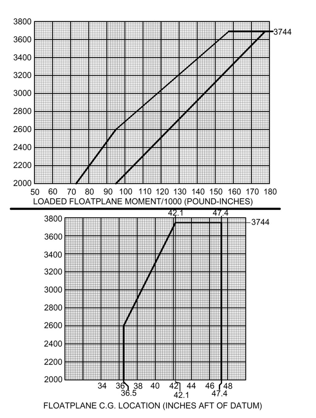
5 5 of 38 SECTION 2. LIMITATIONS CENTER OF GRAVITY LIMITS: Center of Gravity Range: (inches aft of reference datum front face of firewall) (+42.1) to (+47.4) at 3744 lbs. Maximum G.W. (+36.5) to (+47.4) at 2600 lbs. or less with a straight line variation between points given. WEIGHT LIMITS: Maximum Ramp or Dock: Maximum Take-off Floats: Maximum Landing Floats: Maximum Take-off Wheels: Maximum Landing Wheels: Maximum Weight in Baggage Compartment: Maximum Weight in Float Baggage Compartment: AIRSPEED LIMITS: 3755 lbs lbs lbs lbs lbs. NO CHANGE 100 lbs. each Never Exceed Speed (Vne) Max Structural Cruising (Vno) Max Maneuvering Speed (Va) Max. Speed with Flaps (Vfe) KCAS KIAS MPH CAS MPH IAS No Change No Change No Change No Change No Change No Change No Change No Change No Change No Change No Change No Change No Change No Change No Change No Change Max Ldg. Gear Operating Speed (Vlo) Max Ldg. Gear Extended Speed (Vle)
6 6 of 38 MANEUVER LIMITS The maneuver limits defined in the basic handbook are applicable to the amphibian. Avoid slips with wing flaps extended FLAP LIMITATIONS Approved Takeoff Range: 0 to 20. Approved Runway Landing Range: 0 to 30. Approved Water Landing Range: 0 to 30. NOTE: Wing flaps must be retracted to 20 immediately following power application for a balked landing go-around. AIR SPEED INDICATOR MARKINGS: The airspeed indicator markings are the same as shown in the basic markings/flight manual. Due to differences in airspeed calibration and speeds with floats installed, the indicated stall speeds and maximum structural cruising speed vary slightly from airspeed indicator markings. PLACARDS: 1. Aerocet P/N 35A Placard is located in plain view of the pilot: EMERGENCY LANDING GEAR OPERATION If electric driven hydraulic pump fails, use hand operated pump to retract and extend landing gear. Land on sod if gear position is unknown. DO NOT LAND ON WATER UNLESS GEAR IS FULLY RETRACTED
7 7 of 38 PLACARDS: (Cont d) 2. Aerocet P/N Placard is located near the emergency gear hand pump: EMERGENCY HAND PUMP OPERATING INSTRUCTIONS 1. Pull landing gear motor circuit breaker. 2. Move landing gear position switch to desired position. 3. Rotate emergency gear selector valve to desired position. 4. Pump emergency gear hydraulic pump until gear lights show for desired position and there is significant force on the pump handle. Always keep gear selector valve in OFF position (detent engaged handle pointed toward pilot seat) except for emergency operation. 3.Aerocet P/N 35A Placard is located on the instrument panel: IN FLOATPLANE, AMPHIBIAN AND SKIPLANE RETRACT FLAPS TO 20 IMMEDIATELY AFTER APPLYING POWER FOR BALKED LANDING GO-AROUND. 4. Refer to Cessna type data for required fuel placards.
8 8 of 38 PLACARDS: (Cont d) 5. Aerocet P/N 35A Placard on instrument panel: IN FLOATPLANE, AMPHIBIAN AND SKIPLANE AVOID SLIPS WITH FLAPS EXTENDED. 6. Aerocet P/N Placard is located on aft part of console near water rudder handle in the "RETRACT" position: "WATER RUDDER ALWAYS UP EXCEPT WATER TAXIING" 7. Aerocet P/N Placard is located in plain view of the pilot: "AVOID TAIL-LOW TAKEOFFS AND LANDINGS WITH FLOATPLANE STINGER INSTALLED DURING OPERATIONS AS A LANDPLANE 8. Aerocet P/N Placard is located inside the float locker panels: 9. Circuit Breaker Placards: "MAX BAGGAGE: 100 LBS. ARM: 32.4 in. AFT DATUM PUMP PWR, PUMP RELAYS, GR. ADV. ELEC.
9 9 of 38 SECTION 3. EMERGENCY PROCEDURES: Emergency procedures in the FAA approved airplane placards and/or Flight Manual generally apply except for airspeeds which may be different. Emergency landings on water should be done with water rudders up, aircraft slightly tail low on touchdown, and control wheel held full aft as the floatplane decelerates on the water. Emergency landings on land should be done with water rudders up, aircraft in a level attitude on touchdown, and the control wheel full aft after contact. If damage occurs to the floats causing compartments to flood, aggressively shift the weight (people & baggage) in the opposite direction of damage in order to balance the aircraft over the buoyant compartments. ENGINE FAILURE EMERGENCY OPERATIONAL CHECKLISTS ENGINE FAILURE DURING TAKEOFF RUN (ON WATER) 1. Throttle -- IDLE. 2. Control Wheel -- FULL AFT. 3. Mixture -- IDLE CUT-OFF. 4. Ignition Switch -- OFF. 5. Master Switch -- OFF. ENGINE FAILURE DURING TAKEOFF RUN (ON LAND) 1. Throttle -- IDLE. 2. Brakes -- APPLY. 3. Wing Flaps -- RETRACT. 4. Mixture -- IDLE CUT-OFF. 5. Ignition Switch -- OFF. 6. Master Switch -- OFF.
10 10 of 38 FORCED LANDINGS EMERGENCY LANDING ON WATER WITHOUT ENGINE POWER 1. Landing Gear -- UP. 2. Airspeed KIAS (flaps UP) 72 KIAS (flaps DOWN). 3. Mixture -- IDLE CUT-OFF. 4. Fuel Shutoff Valve -- OFF. 5. Ignition Switch -- OFF. 6. Master Switch -- OFF. 7. Water Rudders -- UP. 8. Wing Flaps -- AS REQUIRED. 9. Doors -- UNLATCH PRIOR TO TOUCHDOWN. 10. Touchdown -- SLIGHTLY TAIL LOW. 11. Control Wheel -- HOLD FULL AFT as amphibian decelerates. EMERGENCY LANDING ON LAND WITHOUT ENGINE POWER 1. Landing Gear -- UP on soft or rough ground. DOWN on firm and smooth ground. 2. Airspeed KIAS (flaps UP) 72 KIAS (flaps DOWN). 3. Mixture -- IDLE CUT-OFF. 4. Fuel Shutoff Valve -- OFF. 5. Ignition Switch -- OFF. 6. Master Switch -- OFF. 7. Water Rudders -- UP. 8. Wing Flaps -- AS REQUIRED (30 recommended). 9. Doors -- UNLATCH PRIOR TO TOUCHDOWN. 10. Touchdown -- LEVEL ATTITUDE (if gear is up). SLIGHTLY TAIL LOW (if gear is down). 11. Control Wheel -- FULL AFT (after contact if gear is up). 12. Brakes -- APPLY HEAVILY (if gear is down).
11 11 of 38 LANDING GEAR MALFUNCTION PROCEDURES LANDING GEAR FAILS TO RETRACT 1. Master Switch -- ON. 2. Landing Gear Handle -- CHECK (handle full up). 3. Landing Gear Motor Circuit Breaker -- IN. 4. Emergency Hand Pump Selector Valve -- CHECK (in off position toward pilot seat). 5. Gear Relay Circuit Breaker -- IN. 6. Gear Advisory Circuit Breaker -- IN. 7. Gear Up Lights -- CHECK bulb operation (press-to-test). 8. Main Gear Visual Indicators -- VISUALLY CHECK (at float inspection openings). 9. Landing Gear Handle -- RECYCLE. 10. Landing Gear Motor -- CHECK operation (motor indicator light, ammeter and noise). 11. Cycle the Emergency Hand Pump Selector Valve to UP position and back to OFF (this reduces pressure in the system allowing the pressure switches to sense low pressure allowing the pump to cycle). If the landing gear still does not retract and a water landing is desired: 12. Landing Gear Motor Circuit Breaker -- PULL. 13. Landing Gear Handle -- UP. 14. Emergency Hand Pump Selector Valve -- ROTATE (to UP position clockwise 90 deg.). 15. Emergency Hand Pump -- PUMP (up and down until gear is in UP position - approximately 165 strokes -- there should be significant force on the pump handle with the final stroke). 16. Gear Up Lights -- CHECK ILLUMINATED. 17. Main Gear Visual Indicators -- VISUALLY CHECK (at float inspection openings). Nose gear -- VISUALLY CHECK (gear is nested in the bow of the float).
12 12 of 38 LANDING GEAR MALFUNCTION PROCEDURES LANDING GEAR FAILS TO EXTEND 1. Master Switch -- ON. 2. Landing Gear Handle -- CHECK (handle full down). 3. Emergency Hand Pump Selector Valve -- CHECK (in off position toward pilot seat) 4. Landing Gear Motor Circuit Breaker -- IN. 5. Gear Relay Circuit Breaker -- IN. 6. Gear Advisory Circuit Breaker -- IN. 7. Gear Down Lights -- CHECK bulb operation (press-to-test). 8. Main Gear Visual Indicators -- VISUALLY CHECK (at float inspection openings). 9. Landing Gear Handle -- RECYCLE. 10. Landing Gear Motor -- CHECK operation (motor indicator light, ammeter and noise). 11. Cycle the Emergency Hand Pump Selector Valve to DOWN position and back to OFF (this reduces pressure in the system allowing the pressure switches to sense low pressure allowing the pump to cycle). If the landing gear still does not extend and a wheels-down landing is desired: 12. Landing Gear Motor Circuit Breaker -- PULL. 13. Landing Gear Handle -- DOWN. 14. Emergency Hand Pump Selector Valve -- ROTATE (to DOWN position counterclockwise 90 deg.). 15. Emergency Hand Pump -- PUMP (up and down until gear is in DOWN position - approximately 230 strokes -- there should be significant force on the pump handle with the final stroke). 16. Gear Down Lights -- CHECK ILLUMINATED. 17. Main & Nose Gear Visuals -- VISUALLY CHECK (with mirrors & note that the up indicators on the mains are not visible at the float inspection openings).
13 13 of 38 GEAR UP LANDING (ON LAND) 1. Landing Gear -- CHECK UP (indicator lights and main gear latch fittings). 2. Runway -- SELECT longest smooth ground or grass surface available. 3. Wing Flaps (on final approach). 4. Airspeed KIAS. 5. Master Switch -- OFF. 6. Doors -- UNLATCH PRIOR TO TOUCHDOWN. 7. Touchdown -- LEVEL ATTITUDE. 8. Control Wheel -- FULL AFT (after contact). 9. Mixture -- IDLE CUT-OFF. 10. Fuel Shutoff Valve -- OFF. 11. Ignition Switch -- OFF. AMPLIFIED PROCEDURES MECHANICAL FAILURE If it is ascertained that a mechanical failure has occurred and the gear will not achieve either a gear up or a gear down position with visual confirmation, the best course of action will be dependent upon the nature of the failure and the choices of landing surfaces available. In the unlikely event that a landing gear has failed in an intermediate position, and cannot be moved to either a Gear Up or Gear Down position, the amphibian should be landed on land only. - WARNING - DO NOT land in the water with the wheels either partially or fully extended. If the landing MUST be accomplished on water and the gear is partially or fully extended, it is suggested that a power-on full stall landing with full flaps (30 ) would be the best procedure. Unlatch cabin doors prior to touchdown except for the rear cargo door on the co-pilots side. Flaps must be deployed prior to unlatching the rear cargo door otherwise the flaps will not move with the door unlatched. During deceleration after touchdown, with the gear extended, the float bows will submerge and there is a high probability of flipping the amphibian onto its back causing either fatal or serious injury.
14 14 of 38 SECTION 4. NORMAL PROCEDURES: (NOTE: THESE ITEMS SUPPLEMENT THE CESSNA NORMAL PROCEDURES - BE SURE TO FOLLOW THE CESSNA PROCEDURES EXCEPT AS NOTED BELOW) BEFORE ENTERING FLOATPLANE 1. Inspect the floats and attachment for dents, cracks, punctures, etc. 2. Remove rubber plugs (which serve as stoppers on the standpipe in each float compartment) and pump out any accumulation of water. Reinstall rubber stoppers with enough pressure for a snug fit. (If there is an excess of water, investigate the leakage - if there is red hydraulic fluid in any water, investigate fittings and lines in that bay before proceeding). WARNING: It is up to the pilot to determine whether the floats have taken on water, which could adversely affect CG. Pump both floats before every flight. 3. Landing Gear -- INSPECT. Check the main wheel oleo struts for proper inflation; check the tires for cuts, bruises and proper inflation. NOTE Refer to placards on the main wheel oleo struts for strut inflation procedures. Proper tire inflation for main wheel tires is 55 psi; tire inflation for the nose wheel tires is 70 psi. 4. Inspect locker door latches DETENTS ENGAGED, LATCHES TURNED CLOCKWISE TO STOPS. NOTE: An un-latched locker bay door will cause a howl and may bang against the float struts during flight. Aircraft should be returned to field in normal fashion to avoid potential damage, and to assess any possible problems. However, as with any situation, FLY THE AIRCRAFT! rather than make a rash decision. It is likely that little or no damage will occur to locker door.
15 15 of 38 BEFORE STARTING ENGINE 1. Landing Gear Handle DOWN (amphibian on land), or UP (amphibian on water) 2. Water Rudder Operation CHECK VISUALLY 3. Water Rudders DOWN FOR TAXIING ON WATER UP FOR TAXIING ON LAND 4. Water Rudders CHECK FREEDOM OF MOVEMENT & SECURITY BEFORE TAKEOFF WARNING: It is up to the pilot to determine whether the floats have taken on water, which could adversely affect CG. Pump both floats before every flight. TAKEOFF TAKEOFF ON WATER 1. Landing Gear UP 2. Landing Gear Blue Indicator Lights CHECK ILLUMINATED 3. Water Rudders UP (retraction handle aft) 4. Wing Flaps 20 DEGREES" (second notch) 5. Control Wheel HOLD FAR AFT INITIALLY 6. Power FULL THROTTLE & MAX RPM (advance slowly) 7. Mixture LEAN FOR HIGH DENSITY ALTITUDE 8. Control Wheel MOVE FORWARD TO ATTAIN PLANING ATTITUDE 9. Control Wheel APPLY LIGHT BACK PRESSURE TO LIFT OFF 10. Wing Flaps UP AFTER OBSTACLES ARE CLEARED Never attempt a takeoff without all blue indicator lamps illuminated any gear hanging down will drag the aircraft dangerously into an arc, compromising takeoff distances, and endangering the occupants.
16 16 of 38 TAKEOFF ON LAND 1. Landing Gear DOWN 2. Landing Gear Amber Indicator Lights CHECK ILLUMINATED 3. Water Rudders UP (retraction handle aft) 4. Wing Flaps 20 DEGREES (second notch) 5. Power FULL THROTTLE & MAX RPM (advance slowly) 6. Mixture LEAN FOR HIGH DENSITY ALTITUDE 7. Control Wheel APPLY LIGHT BACK PRESSURE TO LIFT OFF 8. Wing Flaps UP AFTER OBSTACLES ARE CLEARED 9. Landing Gear UP BEFORE LANDING BEFORE LANDING ON WATER 1. Landing Gear -- UP. 2. Landing Gear Blue Indicator Lights -- CHECK ILLUMINATED. 3. Visually check that nose gear are UP During deceleration after a water touchdown, with the gear extended, the float bows will submerge and there is a high probability of flipping the amphibian onto its back causing either fatal or serious injury. 4. Water Rudders -- UP. 5. Wing Flaps BEFORE LANDING ON LAND 1. Landing Gear -- DOWN. 2. Landing Gear Amber Indicator Lights -- CHECK ILLUMINATED. 3. Water Rudders -- UP. 4. Wing Flaps LANDING LANDING ON WATER 1. Touchdown -- SLIGHTLY TAIL LOW. 2. Control Wheel -- HOLD FULL AFT as amphibian decelerates to taxi speed. 3. After landing WATER RUDDERS DOWN
17 17 of 38 LANDING ON LAND 1. Touchdown -- SLIGHTLY TAIL LOW. 2. Control Wheel -- EASE FORWARD to lower wheels gently to runway. 3. Braking -- MINIMUM REQUIRED BALKED LANDING "RETRACT FLAPS TO 20 DEG. IMMEDIATELY AFTER APPLYING FULL POWER FOR GO-AROUND" SECURING AIRPLANE - "FUEL SELECTOR TO RIGHT OR LEFT TANK POSITION TO PREVENT CROSSFEEDING"
18 18 of 38 SECTION 5. PERFORMANCE: ALL MODELS EXCEPT T206H: Airspeed Calibration - Essentially unchanged STALL SPEEDS: POWER OFF, FORWARD CG, 3744 LBS FLAPS UP: 61 KCAS 70 MPH CAS FLAPS DOWN (30 Deg.): 54 KCAS 62 MPH CAS NOTE ALTITUDE LOSS DURING STALL RECOVERY MAY BE AS MUCH AS 200 FEET. CLIMB RATE: EXCEEDS 550 FPM (CAR 3.85a) MODEL T206H: The following information is valid for model T206H which has a turbocharged Lycoming engine (310 hp). GLIDE In the event of engine failure enroute with propeller wind milling, landing gear up, flaps up. RECCOMENDED GLIDE SPEED 83 KCAS 95 MPH CAS Maximum horizontal distance traveled in still air 1.5 NM PER 1,000 FT ALTITUED LOST SINK RATE 1,000 FPM
19 19 of 38 AIRSPEED CALIBRATION NORMAL STATIC SOURCE FLAPS UP KIAS KCAS FLAPS 20 KIAS KCAS FLAPS 30 KIAS KCAS STALL SPEEDS CONDITIONS: Power Off MOST FORWARD CENTER OF GRAVITY ANGLE OF BANK WEIGHT FLAP LBS DEFLECTION KIAS KCAS KIAS KCAS KIAS KCAS KIAS KCAS 3744 UP NOTES: 1. Altitude loss during a stall recovery may be as much as 360 feet. 2. KIAS values are approximate.
20 20 of 38 OBSTACLE TAKEOFF DISTANCE FROM GROUND CONDITIONS: Landing Gear Down, Flaps RPM, 39 inhg Manifold Pressure Paved, Level, Dry Runway Zero Wind Liftoff Speed: 57 KIAS (approximately) Speed at 50 Ft: 69 KIAS 3735 POUNDS MAXIMUM TAKEOFF WEIGHT ON GROUND 0 C 10 C 20 C 30 C 40 C 50 C Grnd Total Grnd Total Grnd Total Grnd Total Grnd Total Grnd Total Press Roll Ft To Roll Ft To Roll Ft To Roll Ft To Roll Ft To Roll Ft To Alt Ft Clear Ft Clear Ft Clear Ft Clear Ft Clear Ft Clear In 50 Ft 50 Ft 50 Ft 50 Ft 50 Ft 50 Ft Feet Obstacle Obstacle Obstacle Obstacle Obstacle Obstacle S.L NOTES: 1. Obstacle takeoff technique as described in Section If brakes are not held, distances are from point where takeoff power is reached. 3. Decrease distances 10% for each 15 knots headwind. For operation in tailwinds up to 10 knots, increase distances by 10% for each 3 knots. 4. For operation on dry, grass, hard runway, increase distances by 15% of the "ground roll" figure. 5. For operation in air colder than this table provides, use the coldest (leftmost) data for takeoff distances. 6. For operation in air warmer than this table provides, use extreme caution. 7. In grey shaded areas total takeoff distances over a 50 foot obstacle are predicted to exceed 1 mile. Use caution!
21 21 of 38 OBSTACLE TAKEOFF DISTANCE FROM WATER CONDITIONS: Landing Gear Up, Flaps RPM, 39 inhg Manifold Pressure Rippled Water Zero Wind Liftoff Speed: 65 KIAS (approximately) Speed at 50 Ft: 69 KIAS 3744 POUNDS 0 C 10 C 20 C 30 C 40 C 50 C Water Total Water Total Water Total Water Total Water Total Water Total Press Run Ft To Run Ft To Run Ft To Run Ft To Run Ft To Run Ft To Alt Ft Clear Ft Clear Ft Clear Ft Clear Ft Clear Ft Clear In 50 Ft 50 Ft 50 Ft 50 Ft 50 Ft 50 Ft Feet Obstacle Obstacle Obstacle Obstacle Obstacle Obstacle S.L NOTES: 1. Obstacle takeoff technique as described in Section Distances are from point where takeoff power is reached. 3. Decrease distances 10% for each 16 knots headwind. For operation in tailwinds up to 10 knots, increase distances by 10% for each 2 knots. 4. For operation in air colder than this table provides, use the coldest (leftmost) data for takeoff distances. Be aware of icing potential. 5. For operation in air warmer than this table provides, use extreme caution. 6. In grey shaded areas total takeoff distances over a 50 foot obstacle are predicted to exceed 1 mile. Use caution! 7. In dark grey shaded areas water run takeoff distances are predicted to exceed 1 mile. Use extreme caution!
22 22 of 38 CONDITIONS: Flaps 20, Gear Down 2500 RPM 39 inhg Mixture - Placard Cowl Flaps Open TAKEOFF RATE OF CLIMB 3735 POUNDS MAXIMUM WEIGHT FOR TAKEOFF FROM GROUND WEIGHT PRESS STD. CLIMB RATE OF CLIMB - FPM LBS ALT TEMP. SPEED -40 C -20 C 0 C 20 C 40 C 60 C FT C KIAS 3735 S.L TAKEOFF CLIMB 1.2V s POUNDS MAXIMUM WEIGHT FOR TAKEOFF FROM GROUND CONDITIONS: Flaps 20, Gear Down 2500 RPM 39 inhg Mixture - Placard Cowl Flaps Open WEIGHT PRESS STD. CLIMB CLIMB GRADIENT - ft/nm LBS ALT TEMP. SPEED -40 C -20 C 0 C 20 C 40 C 60 C FT C KIAS 3735 S.L
23 23 of 38 CONDITIONS: Flaps Up, Gear Up 2500 RPM 39 inhg Mixture - Placard Cowl Flaps Open ENROUTE RATE OF 1.3Vs POUNDS WEIGHT PRESS STD. CLIMB RATE OF CLIMB - FPM LBS ALT TEMP. SPEED -40 C -20 C 0 C 20 C 40 C 60 C FT C KIAS 3744 S.L CONDITIONS: Flaps Up, Gear Up 2500 RPM 39 inhg Mixture - Placard Cowl Flaps Open ENROUTE CLIMB 1.3Vs POUNDS WEIGHT PRESS STD. CLIMB CLIMB GRADIENT - ft/nm LBS ALT TEMP. SPEED -40 C -20 C 0 C 20 C 40 C 60 C FT C KIAS 3744 S.L
24 24 of 38 BALKED LANDING RATE OF 1.3V s POUNDS MAXIMUM WEIGHT FOR LANDING ON GROUND CONDITIONS: Flaps 30, Gear Down 2500 RPM 39 inhg Mixture - Placard Cowl Flaps Open WEIGHT PRESS STD. CLIMB RATE OF CLIMB - FPM LBS ALT TEMP. SPEED -40 C -20 C 0 C 20 C 40 C 60 C FT C KIAS 3550 S.L BALKED LANDING CLIMB 1.3V s0 CONDITIONS: Flaps 30, Gear Down 2500 RPM 39 inhg Mixture - Placard Cowl Flaps Open 3550 POUNDS WEIGHT PRESS STD. CLIMB CLIMB GRADIENT - ft/nm LBS ALT TEMP. SPEED -40 C -20 C 0 C 20 C 40 C FT C KIAS 60 C 3550 S.L
25 25 of 38 OBSTACLE LANDING DISTANCE ON GROUND CONDITIONS: Gear Down, Flaps 30 Propeller Lever - Maximum Power for 3 Descent to Obstacle, Then Gradual Reduction to Idle at Touchdown, Idle After Landing Maximum Braking Paved, Level, Dry Runway Zero Wind Speed at 50 Ft: 67 KIAS 3550 POUNDS MAXIMUM LANDING WEIGHT ON GROUND 0 C 10 C 20 C 30 C 40 C 50 C Grnd Total Grnd Total Grnd Total Grnd Total Grnd Total Grnd Total Press Roll Ft To Roll Ft To Roll Ft To Roll Ft To Roll Ft To Roll Ft To Alt Ft Clear Ft Clear Ft Clear Ft Clear Ft Clear Ft Clear In 50 Ft 50 Ft 50 Ft 50 Ft 50 Ft 50 Ft Feet Obstacle Obstacle Obstacle Obstacle Obstacle Obstacle S.L NOTES: 1. Obstacle landing technique as described in Section Decrease distances 10% for each 16 knots headwind. For operation in tailwinds up to 10 knots, increase distances by 10% for each 2 knots. 3. For operation in air colder than this table provides, use the coldest (leftmost) data for takeoff distances. 4. For operation in air warmer than this table provides, use extreme caution. 5. For operation on a dry, grass runway, lncrease distances by 40% of the "ground roll" figure.
26 26 of 38 OBSTACLE LANDING DISTANCE ON WATER CONDITIONS: Gear Up, Flaps 30 Propeller Lever - Maximum Power for 3 Descent to Obstacle, Then Gradual Reduction to Idle at Touchdown, Idle After Landing Rippled Water Zero Wind Speed at 50 Ft: 67 KIAS 3661 POUNDS MAXIMUM LANDING WEIGHT ON WATER 0 C 10 C 20 C 30 C 40 C 50 C Grnd Total Grnd Total Grnd Total Grnd Total Grnd Total Grnd Total Press Roll Ft To Roll Ft To Roll Ft To Roll Ft To Roll Ft To Roll Ft To Alt Ft Clear Ft Clear Ft Clear Ft Clear Ft Clear Ft Clear In 50 Ft 50 Ft 50 Ft 50 Ft 50 Ft 50 Ft Feet Obstacle Obstacle Obstacle Obstacle Obstacle Obstacle S.L NOTES: 1. Obstacle landing technique as described in Section Decrease distances 10% for each 16 knots headwind. For operation in tailwinds up to 10 knots, increase distances by 10% for each 2 knots. 3. For operation in air colder than this table provides, use the coldest (leftmost) data for takeoff distances. 4. For operation in air warmer than this table provides, use extreme caution.
27 27 of 38 SECTION 6. WEIGHT AND BALANCE: The airplane equipped with Aerocet 3400 amphibious seaplane floats must be loaded in accordance with the limitations in Section 2. These are shown as an aircraft weight/moment envelope or an aircraft weight versus c.g. location chart. Note: It is the responsibility of the airplane owner and pilot to insure that the airplane is loaded properly. CESSNA 206 WITH AEROCET AMPHIBIOUS 3400 SERIES FLOATS SAMPLE AIRPLANE YOUR AIRPLANE SAMPLE LOADING PROBLEM Arm Weight Moment Arm Weight Moment Inches Pounds lb.-ins./1000 Inches Pounds lb.-ins./1000 (1) Basic Empty Weight (2) OIL (3) Usable Fuel (MAX 65) 47 gallons (4) Pilot and Copilot (STA. 34 TO 48) (5) PASSENGERS + BAGGAGE CENTER Row Passengers (STA. 69 TO 79) AFT Row Passengers (STA. 92 TO 100) AFT BAGGAGE (STA. 109 TO 145; 120LBS MAX ) (6) NO SEATS CARGO AREAS CARGO "A" (STA. 10 TO 50) CARGO "B" (STA. 50 TO 84) CARGO "C" (STA. 84 TO 109) CARGO "D" (STA. 109 TO 145) (7) OPTIONAL CARGO POD (STA. 10 TO 85) (300 LBS. MAX) (8) FLOAT CARGO LOCKERS (STA. 15 TO 51) (100LBS. MAX EACH SIDE) (9) Ramp CG, Weight And Moment (10) Available useful 3744 GW 4 (11) Located the (9) point 161.2) on the Center of Gravity Moment Envelope, and since this point falls within the evelope, the loading is acceptable. * Maximum allowable cargo loads will be determined by the type and number of tie-downs used, as well as by the airplane weight and C.G. limitation. Floor loading must not exceed 200lbs. per square foot.
28 28 of 38
29 29 of 38 SECTION 7. AIRPLANE AND SYSTEMS DESCRIPTIONS: In addition to the Aerocet 3400 amphibious seaplane float installation the aircraft must incorporate the Cessna approved seaplane kit and an approved three blade propeller according to the STC. As a result of these installations, the floatplane is identical to the landplane with the following exceptions: CHANGE FROM LANDPLANE TO AMPHIBIOUS SEAPLANE Installation of Aerocet amphibious floats include the following modifications or additions to a landplane. This is an overview. The complete information resides in Cessna manuals, Aerocet drawings and the STC. Cessna Float Kit Modifications to Airplane 1. Fuselage strengthening installed at factory. 2. V-brace. Hoisting rings. (installed at factory or later) 3. Aileron Fences. (also available from Aerocet) 4. Empennage changes: Vertical fin and beacon modified, ventral fin, rudder, fairings, stinger, dual tail tie-down rings. 5. Rudder trim bungee replaced with softer. 6. Water rudder bellcranks. 7. Cowl flap rod extensions on models A through G. 8. Exhaust extensions on models A through G. Aerocet Float Installation 9. Float undercarriage: float hulls, spreader bars, struts, flying wires, boarding steps, water rudder rigging, retractable landing gear system. 10. Hydraulic lines, reservoir and pump with associated electrical wiring for landing gear operation. 11. Propeller listed in Section 1 of this AFMS. 12. Exhaust pipe modification on H-model 13. Wing mounted mirrors. 14. In cockpit: - Gear selector with light and audio advisories - Placards - Emergency hand pump handle - Water rudder retraction handle Adjustments for Seaplane 15. Elevator trim rigging changed 16. Flap travel limited to 30 deg
30 30 of 38 AMPHIBIOUS FLOATS REMOVED FOR LANDPLANE OPERATIONS When the floats (item 9 above) are replaced with landplane landing gear the following items need to be changed. Other items listed above, including the propeller and the H-models exhaust extension, can remain on the airplane. 4. Ventral fin removed. 5. Rudder trim bungee replaced. 6. Water rudder bellcranks removed. 7. Cowl flap rod extensions removed on models A through G. 8. Exhaust extensions removed on models A through G. 15. Elevator trim rigging adjusted to landplane. 16. Flap travel maximum set to 40 deg. AMPHIBIOUS LANDING GEAR SYSTEM The landing gear incorporated within the amphibious floats on this airplane is a retractable, quadricycle type with two full swiveling nose (or bow) wheels and two main wheels. Shock absorption is provided by air oil shock struts for the main gear and composite leaf springs for the bow gear. Each main wheel is equipped with a hydraulically-actuated disc-type brake. Normal landing gear extension and retraction accomplished by hydraulic actuators for each gear. The hydraulic system is powered by a reversible, electrically-driven hydraulic pump located just forward of fuselage station Hydraulic system fluid level should be checked at 25-hour intervals by viewing the sight glass on the side of the pump. Fill to within ½ of the top of the sight glass by removing the vented plug and using MIL-H-5606 hydraulic fluid. Hydraulic pump operation is initiated by moving the landing gear switch on the gear control unit to either the up or down position. The landing gear will travel to the position selected, cycling the electrically-driven hydraulic pump. The pump is shut off by pressure switches. When the pressure switch senses a certain amount of pressure in the hydraulic line, which the electric pump is forcing fluid through, it will send a signal to the motor relay shutting down the pump. The pressure increases at the end of operation when all the actuators have traveled to the end of their stroke. Eight position-indicator lights (four gear up and four gear down) are provided to show landing gear position. An additional indicator light shows that the landing gear pump motor is in operation. The landing gear system is also equipped with an emergency hand pump with a selector valve.
31 31 of 38 G600 Landing Gear Advisory Unit LANDING GEAR HANDLE The landing gear handle is an electrical switch mounted within a control unit on the instrument panel, and has two positions (UP for gear up and DOWN for gear down) which give a mechanical indication of the gear position selected. From either position, the handle must be pulled out to clear a detent before it can be repositioned. Moving the handle to UP or DOWN will start the reversible, electrically-driven hydraulic pump in the selected direction of gear travel. Operation of the landing gear system will not begin until repositioning of the handle is complete. INDICATOR LIGHTS Eight indicator lights are mounted on the Landing Gear Advisory Unit adjacent to the landing gear handle. The four blue indicator lights, labeled WATER, (positioned respective to their location on the float, i.e. top left front left gear) show by their illumination that the landing gear is up.
32 32 of 38 The four amber indicator lights, labeled LAND, illuminate when the landing gear is down. Neither set of lights is illuminated when the landing gear is in transit. The single red indicator light, labeled PUMP, comes on when current is being supplied to the landing gear pump motor. If the motor continues running during flight or goes on and off repeatedly, the motor should be shut off by pulling the LANDING GEAR MOTOR circuit breaker, since continual running of the motor can result in premature motor failure. Prior to landing, the circuit breaker should be pushed in to reactivate the circuit. If an indicator light should fail to come on when pressed for testing check wiring and gear position. Beyond this, reference the service manual for the gear advisory, document A The WATER, LAND, and PUMP light circuits are protected by the Landing Gear Advisory circuit breaker, and are therefore independent of the landing gear motor circuit and will function when using the emergency hand pump. NOTE: The pilot should always visually check the nose gear before attempting a water landing to assure that it is up regardless of lights. If the pull ram mechanically fails, it could travel and show a light but not be connected to the nose gear itself leaving the nose gear in the down position. During deceleration after a water touchdown, with the gear extended, the float bows will submerge and there is a high probability of flipping the amphibian onto its back causing either fatal or serious injury. AUDIO ADVISORY OPERATION The Landing Gear Advisory Unit, GC600, includes an audio output that is connected to an audio output source (i.e. radio or audio panel) for verbal pilot information regarding gear position. A static and pitot pressure source is connected to the Unit which determines airspeed. The Landing Gear Advisory Unit has an arming speed set by the factory and a trigger point set at approximately 80 knots. Refer to section 2.3 of the Gear Advisory Service Manual A for further information. The GC600 audio announcements are dependent on airspeed ARM and TRIGGER settings, which are factory pre-set for the aircraft type. The GC600 is armed by the aircraft exceeding the pre-set airspeed. As the aircraft begins its approach, it slows its airspeed passing through the pre-set trigger speed, and sounding an audio announcement to indicate the gear position. If the gear is not in a fully retracted or a fully deployed position, then a gear unsafe announcement will sound.
33 33 of 38 With all blue lights on, the announcement will sound, Water landing, gear is up for water landing. This announcement will continue to repeat and complete the phrase, until the upper CANCEL button is pushed, or the aircraft speed is increased above the trigger airspeed setting. With all amber lights on, the announcement will sound, Runway landing, gear is down for runway landing. This announcement will continue to repeat and complete the phrase, until the lower CANCEL button is pushed, or the aircraft speed is increased above the trigger airspeed setting. If the condition exists where any indicator light within the WATER quadrant, or RUNWAY quadrant, fails to illuminate, then the announcement will sound, Gear is unsafe, check gear. This announcement will continue to repeat and complete the phrase, until either upper or lower Cancel button is pushed to de-activate. The TEST button in the center left position of the face, when depressed, will sound an audible announcement indicating the current position of the gear. One of three announcements listed above, will repeat as long as the button is depressed. This announcement will continue to repeat and complete the phrase, until the button is released. (It should be clearly noted that the audio advisory side of the Landing Gear Advisory Unit by Aerocet, Inc. does not alleviate the pilot s responsibility to visually check the location of the landing gear prior to landing, especially to assure the gear is up when making a water landing. Audio systems may be turned down or fail.) NOTE: The pilot should always visually check the nose gear before attempting a water landing to assure that it is up regardless of audio indication. If the pull ram mechanically fails, it could travel and show a light or give an audio indication but not be connected to the nose gear itself leaving the nose gear in the down position.
34 34 of 38 LANDING GEAR OPERATION To retract or extend the landing gear, pull out on the landing gear handle and move it to the desired position. When the handle is positioned, electrical power is directed to one of two solenoid relays, which energize the reversible electric motor. The Emergency Hand Pump lever must be in the OFF position (which points the end of the handle toward the pilot seat.) in order for the electric pump to pump fluid. The electric motor powers the hydraulic pump and actuates two hydraulic gear actuators in each float in the appropriate direction. During operation of the landing gear motor, the PUMP indicator light is illuminated. When the hydraulic rams have enough resistance on them, typically by achieving full travel of the ram, pressure will build triggering the electric pressure switches that in turn activate the relays to turn the pump off. Proximity sensors are located on all four gear, feeding appropriate gear position to the Landing Gear Advisory Unit illuminating the appropriate (WATER or LAND) lights. Again, the pressure in the system turns the pump on and off, not the proximity sensors. EMERGENCY HAND PUMP SELECTOR VALVE AND HAND PUMP A three position emergency hand pump selector valve combined with a single action hand pump is located between the crew seats and is for use in the event the normal hydraulic system fails. The selector valve has three positions, labeled UP, DOWN, and OFF which points the end of the handle toward the pilot seat. To select gear position with the emergency hand pump selector, rotate the handle to UP (clockwise 90 degrees) or DOWN (counterclockwise 90 degrees).
35 35 of 38 NOTE The emergency hand pump selector valve must be rotated to the OFF position (in a detent with the end of the handle pointing toward the pilot seat) during normal system operation. If the selector valve is in any other position, it provides a by-pass for hydraulic pressure and the landing gear may not function properly. During deceleration after a water touchdown, with the gear extended, the float bows will submerge and there is a high probability of flipping the amphibian onto its back causing either fatal or serious injury. EMERGENCY HAND PUMP SELECTOR VALVE AND HAND PUMP: (Cont d) Prior to utilizing the emergency hand pump, pull the LANDING GEAR MOTOR circuit breaker to ensure deactivation of the electric hydraulic pump, then rotate the hand pump selector valve to the desired position (UP or DOWN). Actuate the hand pump up and down (approximately 230 strokes for extension and 165 strokes for retraction) until the landing gear reaches the selected position. When the gear reaches the selected position, the appropriate gear position indicator lights will illuminate and the hand pump should be pumped until there is significant force on the pump handle with the final stroke. For complete emergency procedures, refer to Section 3 of this supplement.
36 36 of 38 SECTION 8. AIRPLANE HANDLING, SERVICE, AND MAINTENANCE INTRODUCTION Airplane handling, service, and maintenance in the basic handbook applies, in general, to the amphibian. The following recommended procedures apply specifically to amphibian operation. (Cleaning, servicing and maintenance of the amphibious floats should be accomplished as suggested in the Aerocet, Inc amphibian Service and Maintenance Manual.) MOORING Proper securing of the amphibian can vary considerably, depending on the type of operation involved and the facilities available. Each operator should use the method most appropriate for his operation. Some of the most common mooring alternatives are as follows: 1. The amphibian can be moored to a buoy, using a yoke tied to the forward float cleats, so that it will freely weathervane into the wind. 2. The amphibian can be secured to a dock using the fore and aft cleats of one float, although this method is generally not recommended unless the water is calm and the amphibian is attended. 3. The amphibian may be removed from the water (by use of a special lift under the spreader bars) and secured by using the wing tie-down rings and float cleats. If conditions permit the amphibian to be beached (with the landing gear retracted), ensure that the shoreline is free of rocks or abrasive material that may damage the floats. 4. The amphibian may be taxied from the water onto land if a hard surface ramp is available by extending the landing gear just prior to reaching the ramp area. The amphibian should then be tied down using procedures similar to the landplane.
37 37 of 38 BEACHING HEELING IN (stern of the floats on the beach) or NOSING INTO SHALLOW GRADIENT WATER The amphibian may be heeled into a beach, but with caution. Also use caution when beaching, nose in, at shallow shore gradients. The wheel well area can scoop sand, mud, rocks, or clay. A rock (deflector) shield is provided to help prevent the debris from collecting underneath the main gear truck. If the plane is secured with the step area embedded in the sand, wave action can wash sand into the wheel well area. Clay or mud can also stick in this area posing a problem. This can reduce clearances, because of debris buildup, preventing the main gear truck from extending to the full gear down position. The main landing gear has tremendous leverage as it travels into its over-center position, and can damage the float and gear truck if there is a restriction. A method (no guarantees) of cleansing this area is proposed. With the gear still retracted, after leaving the beach, aggressively plow the floats to flush this area. This puts the plane at a high angle of attack and introduces water for flushing. Do this a couple of times and even go up on the step for a moment. WARNING Water operations with landing gear extended may be hazardous in shallow water or in areas where submerged obstacles exist. High speed water operations with landing gear extended is never safe. After washing the area and the airplane is at idle power lower the gear. Assure that all the amber lights illuminate, indicating gear down position is achieved. If a main gear light does not illuminate, proceed to inspect the problem. Ideally, finding a float dolly which will lift the floats out of the water with the gear retracted, will give opportunity to investigate the problem.
38 38 of 38 SERVICING Service the airplane in accordance with the basic handbook. Special attention should be given to engine oil and landing gear servicing of the amphibian. Some of the following service information is contained in the basic handbook, and is repeated here for your convenience. AMPHIBIOUS LANDING GEAR NOSE WHEEL TIRE PRESSURE: 70 PSI on , 4-Ply Rated Tires. MAIN WHEEL TIRE PRESSURE: 55 PSI on , 8-Ply Rated Tires. MAIN GEAR SHOCK STRUTS: Keep filled with MIL-H-5606 hydraulic fluid and inflated with nitrogen to 495 PSI for main gear shock struts with no load. HYDRAULIC FLUID RESERVOIR: Check and service with MIL-H-5606 hydraulic fluid every 25 hours of flight time. Fill to within ½ of the top of the sight glass by removing the vented plug. CAUTION: When servicing the landing gear system, the procedures and precautions contained in the Service and Maintenance Manual for Aerocet 3400 Amphibious Floats must be followed.
AEROCET 3400 AMPHIBIOUS FLOATS
 FOUND SUPPLEMENT M400-S10 Transport Canada Approved Flight Manual Supplement For AEROCET MODEL 3400 AMPHIBIOUS FLOATS This supplemental manual is applicable to Aerocet Model 3400 amphibious float equipped
WIPLINE 3450 SEAPLANE FLOATS
 FOUND SUPPLEMENT M400-S08 Transport Canada Approved Flight Manual Supplement For WIPLINE MODEL 3450 SEAPLANE FLOATS This supplemental manual is applicable to Wipline Model 3450 seaplane float equipped
CSSna HIAWK FLOATPLANE WNER'S MANUAL SUPPLEMENT D CES-100-3/73
 CSSna HIAWK FLOATPLANE WNER'S MANUAL SUPPLEMENT D709-13-CES-100-3/73 2220 108 PERFORMANCE - SPECIFICATIONS FLOATPLANE 1620ft 148 GROSS WEIGHT lbs SPEED: Top Speed at Sea Level mph u Cruise, 75% Power at
INCORPORATED. Supplemental Airplane Flight Manual FAA APPROVED. SUPPLEMENTAL AIRPLANE FLIGHT MANUAL FOR Cessna 180, 180A - 180F Series Floatplanes
 ISSUE QA'IS' REVISION DAr, 4/8/08 AER~ET Supplemental Airplane Flight Manual 'U!'Tne" Cessna 180, 180A-180F Series Floatplanes 1 of 10 A-IDOlS FAA APPROVED SUPPLEMENTAL AIRPLANE FLIGHT MANUAL FOR Cessna
AEROCET MODEL 3500L/3500 FLOATS
 Transport Canada Approved Flight Manual Supplement For AEROCET MODEL 3500L/3500 FLOATS This supplemental manual is applicable to Aerocet Models 3500L and 3500 float equipped airplanes. This Supplement
Bonanza/Debonair Pilots
 Bonanza/Debonair Pilots Completing this worksheet is a great way to reinforce the proper speeds for operating your Bonanza or Debonair under varying operating conditions, and to understand the changes
Tecnam Eaglet Standard Operating Procedures and Maneuvers Supplement
 Tecnam Eaglet Standard Operating Procedures and Maneuvers Supplement Normal Takeoff Flaps Take Off Trim set Fuel pump on Check for traffic Line up on white stripe Full power Stick should be located in
Single Engine Complex Training Supplement PA28R-201 Piper Arrow III (Spring 2016 Revision)
") Single Engine Complex Training Supplement PA28R-201 Piper Arrow III (Spring 2016 Revision) V-speed Quick Reference V-Speed KIAS Description Airspeed Indicator Marking VSO 55 Stall speed in landing configuration
Single Engine Complex Training Supplement PA28R-201 Piper Arrow III (Spring 2016 Revision) V-speed Quick Reference V-Speed KIAS Description Airspeed Indicator Marking VSO 55 Stall speed in landing configuration
Uncontrolled Copy AEROCET 3400 AMPHIBIOUS FLOATS. Transport Canada Approved Flight Manual Supplement For SUPPLEMENT S01
 FOUND SUPPLEMENT S01 Transport Canada Approved Flight Manual Supplement For AEROCET MODEL 3400 AMPHIBIOUS FLOATS This supplemental manual is applicable to Aerocet Model 3400 amphibious float equipped airplanes.
SECTION 1 - GENERAL SECTION 2 - LIMITATIONS SECTION 3 - EMERGENCY PROCEDURES
 Beechcraft Bonanza Models. 35-33,35-A33,35-833,35-C33,35C33A, E33, E33A, E33C, F33, F33A. F33C, G33, A35, 835, C35, D35, E35, F35, G35,35R, H35, 535, K35, M35, N35, P35,S35, V35, V35A, V358,36, A36, A36TC
NORMAL TAKEOFF AND CLIMB
 NORMAL TAKEOFF AND CLIMB CROSSWIND TAKEOFF AND CLIMB The normal takeoff is one in which the airplane is headed directly into the wind or the wind is very light, and the takeoff surface is firm with no
PROCEDURES GUIDE CESSNA 172N SKYHAWK
 PROCEDURES GUIDE CESSNA 172N SKYHAWK THESE PROCEDURES ARE DESIGNED TO PROVIDE STANDARDIZED METHODS UNDER NORMAL CONDITIONS. AS CONDITIONS CHANGE, THE PROCEDURES WILL NEED TO BE ADJUSTED. PASSENGER BRIEFING
Seaplane Rating Add-On N3909Q Training Syllabus
 Seaplane Rating Add-On N3909Q Training Syllabus 1971 Cessna 172L Floatplane N3909Q AIRCRAFT SPECIFICATIONS Airspeeds Vs0 40 Vs1 45 Vx 65 Vy 85 Vfe 90 Va 96 Vno 127 Vne 140 Best Glide 80 *All speeds in
Commercial Maneuvers for PA28RT-201
 Commercial Maneuvers for PA28RT-201 Cruise checklist: Power 23'', 2400 RPM (23, 24) Lean mixture Fuel Pump Off (Check positive fuel pressure) Landing light Off Pre-Maneuver Checklist in the Takeoff configuration
SUPPLEMENT SEPTEMBER 2010 HIGH ALTITUDE TAKEOFF AND LANDING (ABOVE 14,000 FEET PRESSURE ALTITUDE) MODEL AND ON 68FM-S28-00 S28-1
 MODEL AND ON 68FM-S28-00 S28-1") MODEL 680 680-0001 AND ON HIGH ALTITUDE TAKEOFF AND LANDING (ABOVE 14,000 FEET PRESSURE ALTITUDE) COPYRIGHT 2010 CESSNA AIRCRAFT COMPANY WICHITA, KANSAS, USA 15 SEPTEMBER 2010 S28-1 SECTION V - SUPPLEMENTS
MODEL 680 680-0001 AND ON HIGH ALTITUDE TAKEOFF AND LANDING (ABOVE 14,000 FEET PRESSURE ALTITUDE) COPYRIGHT 2010 CESSNA AIRCRAFT COMPANY WICHITA, KANSAS, USA 15 SEPTEMBER 2010 S28-1 SECTION V - SUPPLEMENTS
ABS/BPPP Performance Worksheet: Baron/Travel Air Pilots
 ABS/BPPP Performance Worksheet: Baron/Travel Air Pilots This worksheet is the homework for BPPP Initial pilots to complete before their BPPP flight. It s designed to help the pilot develop a deep understanding
FLIGHT MANUAL SUPPLEMENT
 FLIGHT MANUAL SUPPLEMENT HUSKY / RF 8001 SKIS This supplement is valid for The Husky A-1. The following derivates of the Husky may use this Supplement after the approval of a minor change to operate the
General. Procedure Checklists. Emergency Procedures. FSD Aerostar 700P Superstar
 General The recommended procedures for coping with various types of emergencies and critical situations are provided in this section. These procedures are suggested as a course of action for coping with
CESSNA 172-SP PRIVATE & COMMERCIAL COURSE
 CESSNA 172-SP PRIVATE & COMMERCIAL COURSE University of Dubuque INTENTIONALLY LEFT BLANK Revision 1 Standard Operating Procedures 1 CALLOUTS CONDITION Parking Brake Released After Takeoff Power has been
FAA-S-ACS-6 June 2016 Private Pilot Airplane Airman Certification Standards. Task ACS Settings
 FAA-S-ACS-6 June 2016 Private Pilot Airplane Airman Certification Standards Cessna 172: mixture rich, carb heat out if below the green arc. Clearing Turns all manuevers! Task ACS Settings Traffic Pattern
C-130 Reduction in Directional Stability at Low Dynamic Pressure and High Power Settings
 C-130 Reduction in Directional Stability at Low Dynamic Pressure and High Power Settings The C-130 experiences a marked reduction of directional stability at low dynamic pressures, high power settings,
N7387D Floatplane Rating Add-On Training Syllabus
 N7387D Floatplane Rating Add-On Training Syllabus 1957 Piper PA-18 Super Cub Floatplane N7387D AIRCRAFT SPECIFICATIONS Airspeeds Vs0 40 Vs 44 Vx 55 Vy 70 Vfe 80 Best Glide 70 *All speeds in MPH Engine
Compiled by Matt Zagoren
 The information provided in this document is to be used during simulated flight only and is not intended to be used in real life. Attention VA's - you may post this file on your site for download. Please
CIVIL AIR PATROL United States Air Force Auxiliary Cadet Program Directorate. Cessna 172 Maneuvers and Procedures
 CIVIL AIR PATROL United States Air Force Auxiliary Cadet Program Directorate Cessna 172 Maneuvers and Procedures This study guide is designed for the National Flight Academy Ground School. The information
Normal T/O Procedure. Short Field T/O Procedure
 Normal T/O Procedure Add full power: Engine Instruments green Airspeed alive 1,000 AGL Accelerate to enroute climb 85 KIAS Complete climb check Vr = 55-60 Vy 79 KIAS Prior to Receiving T/O Clearance Complete
ROTORCRAFT FLIGHT MANUAL SUPPLEMENT. TO THE BELL MODEL UH-1H ROTORCRAFT FLIGHT MANUAL for the APICAL EMERGENCY FLOAT KIT
 SUPPLEMENT TO THE for the APICAL EMERGENCY FLOAT KIT This supplement is to be used when the rotorcraft is modified by the installation of the Apical Float Kit 644.3201 for UH-1H helicopters. The information
Beechcraft Duchess 76 Maneuver Notes
 Beechcraft Duchess 76 Maneuver Notes I. Maneuver notes for Performance (AOA V), Slow Flight and Stalls (AOA VIII), Emergency Operations (AOA X), and Multiengine Operations (AOA XI) a. Maneuvers addressed:
AIRCRAFT PRIMARY CONTROLS A I R C R A F T G E N E R A L K N O W L E D G E
 1.02.02 AIRCRAFT PRIMARY CONTROLS 1. 0 2 A I R C R A F T G E N E R A L K N O W L E D G E CONTROLLING AIRCRAFT AIRCRAFT CONTROL SYSTEM In general, we use control inputs of the following devices in cabin:
SR22 Airplane Flight Manual (AFM) Temporary Change
 Temporary Change") Cirrus Design TPOH AFM Temporary Change Airplane Flight Manual (AFM) Temporary Change Information in this Temporary Change adds to, supersedes, or deletes information in the basic Pilot s Operating Handbook.
Cirrus Design TPOH AFM Temporary Change Airplane Flight Manual (AFM) Temporary Change Information in this Temporary Change adds to, supersedes, or deletes information in the basic Pilot s Operating Handbook.
ENVIRONMENTAL CONTROL SYSTEM (ECS)
") ENVIRONMENTAL CONTROL SYSTEM (ECS) DESCRIPTION AND OPERATION The ECS system comprises the following subsystems: bleed air management, environmental control unit (ECU) temperature control air distribution
ENVIRONMENTAL CONTROL SYSTEM (ECS) DESCRIPTION AND OPERATION The ECS system comprises the following subsystems: bleed air management, environmental control unit (ECU) temperature control air distribution
Cessna 172R Profiles
 Cessna 172R Profiles TRAFFIC PATTERNS (Verify pattern altitude) Start your first climbing turn within 300' of pattern altitude Enter 45 degree angle to the downwind leg Depart the traffic pattern straight-out,
See the diagrams at the end of this manual for judging position locations.
 Landing Events Penalties General Judges should use airport diagrams, satellite pictures or other means to determine, as accurately as possible, assessments of landing pattern penalties. Judges should be
DISCLAIMER: This scanned version of the Schweizer 2-33A Sailplane manual is provided without warranty of completeness or accuracy.
 DISCLAIMER: This scanned version of the Schweizer 2-33A Sailplane manual is provided without warranty of completeness or accuracy. It is solely as a service to builders of scale model aircraft who are
Cessna 152 Standardization Manual
 Cessna 152 Standardization Manual This manual is to be utilized in conjunction with the manufacturers approved POH/ AFM and the Airplane Flying Handbook (FAA-H-8083-3A). This manual should be used as a
AIR CONDITIONING AND PRESSURIZATION CONTROLS AND INDICATORS
 AIR CONDITIONING AND PRESSURIZATION CONTROLS AND INDICATORS Air conditioning control panel 1 MIN MAX Page 1 Air conditioning control panel 2 MIN MAX Page 2 Air conditioning control panel 3 MIN MAX Page
Weighing your Seabee
 Weighing your Seabee Note: The following procedure must be supervised and signed off by a qualified A&P and the final paperwork must be included in the Aircraft Records. The actual weights must be included
FFI Formation Guidelines and Standard Procedures Mooney Supplement (28 Dec, 2018; Rev 12)
") FFI Formation Guidelines and Standard Procedures Mooney Supplement (28 Dec, 2018; Rev 12) This document describes formation flight differences between RV and Mooney aircraft. In conjunction with the FFI
FFI Formation Guidelines and Standard Procedures Mooney Supplement (28 Dec, 2018; Rev 12) This document describes formation flight differences between RV and Mooney aircraft. In conjunction with the FFI
 www.guatemala-skies.com GUATEMALA GENERAL AVIATI INFORMATI TO GO Contents: Cessna 172 XP 1977 V Speeds & checklist Guatemala Radio Frequencies Emergency Transponder Codes & ATC Light Signals MGGT airport
Cessna 172S Skyhawk Standardization Manual
 Cessna 172S Skyhawk Standardization Manual This manual is to be utilized in conjunction with the manufacturers approved POH/ AFM and the Airplane Flying Handbook (FAA-H-8083-3A). This manual should be
Piper PA Seminole 1. Standardization Manual
 Piper PA-44-180 Seminole Standardization Manual This manual is to be utilized in conjunction with the manufacturers approved POH/AFM and the Airplane Flying Handbook (FAA-H-8083-3A). This manual should
S-Tec System 55 Autopilot
 Cirrus Design Section 9 Pilot s Operating Handbook and FAA Approved Airplane Flight Manual Supplement for S-Tec System 55 Autopilot When the S-Tec System 55 Autopilot is installed in the Cirrus Design,
Jabiru J230-SP Section 10
 Jabiru J230-SP Section 10 Section 10 10.1 Introduction This section contains information on the basic flight controls, door operation, and entry and egress, followed by a flight training outline compiled
PROCEDURES GUIDE. FLIGHT MANEUVERS for the SPORT PILOT
 Page 1 of 10 PROCEDURES GUIDE FLIGHT MANEUVERS for the SPORT PILOT * Author s Note: Whereas this procedures guide has been written for a specific application, it can easily be modified to fit many different
MANEUVERS GUIDE. Liberty Aerospace 1383 General Aviation Drive Melbourne, FL (800)
") MANEUVERS GUIDE Liberty Aerospace 1383 General Aviation Drive Melbourne, FL 32935 (800) 759-5953 www.libertyaircraft.com Normal/Crosswind Takeoff and Climb 1. Complete the runup and before takeoff checklist.
MANEUVERS GUIDE Liberty Aerospace 1383 General Aviation Drive Melbourne, FL 32935 (800) 759-5953 www.libertyaircraft.com Normal/Crosswind Takeoff and Climb 1. Complete the runup and before takeoff checklist.
Visualized Flight Maneuvers Handbook
 Visualized Flight Maneuvers Handbook For High Wing Aircraft Third Edition For Instructors and Students Aviation Supplies & Academics, Inc. Newcastle, Washington Visualized Flight Maneuvers Handbook for
AVIATION INVESTIGATION REPORT A00P0157 COLLISION WITH WATER
 Transportation Safety Board of Canada Bureau de la sécurité des transports du Canada AVIATION INVESTIGATION REPORT A00P0157 COLLISION WITH WATER WHISTLER AIR SERVICES LTD. CESSNA 185 FLOATPLANE C-GEJC
NORMAL TAKEOFF PILOT TRAINING MANUAL KING AIR 200 SERIES OF AIRCRAFT
 NORMAL TAKEOFF Climb-Out 1. Accelerate to 160 KIAS 2. Landing/Taxi lights: Out 3. Climb Checklist complete 1. 160 KIAS up to 10,000 ft 2. Decrease 2 KIAS per 1,000 ft above 10,000 ft to 130 KIAS at 25,000
Takeoff Performance. A 1 C change in temperature from ISA will increase or decrease the takeoff ground roll by 10%.
 The precise pilot does not fly by rules of thumb, axioms, or formulas. But there are times when knowledge of an approximate way to calculate things or knowledge of a simple rule can pay big dividends.
TECHNIQUES FOR OFF AIRPORT OPERATIONS
 Off Airport Ops Guide TECHNIQUES FOR OFF AIRPORT OPERATIONS Note: This document suggests techniques and procedures to improve the safety of off-airport operations. It assumes that pilots have received
TAILWHEEL AIRPLANES LANDING GEAR TAXIING
 Ch 13.qxd 5/7/04 10:04 AM Page 13-1 TAILWHEEL AIRPLANES Tailwheel airplanes are often referred to as conventional gear airplanes. Due to their design and structure, tailwheel airplanes exhibit operational
Mountain Fury Mountain Search Flying Course Syllabus
 Mountain Fury Mountain Search Flying Course Syllabus Goals 1. Pilots who complete this program will be able to perform with precision and confidence all of the tasks and flight maneuvers required for safe
Front Cover Picture Mark Rasmussen - Fotolia.com
 Flight Maneuvers And Stick and Rudder Skills A complete learn to fly handbook by one of aviation s most knowledgeable and experienced flight instructors Front Cover Picture Mark Rasmussen - Fotolia.com
CAP-USAF FLIGHT MANEUVERS GUIDE
 CAP-USAF FLIGHT MANEUVERS GUIDE February 2012 Flight Maneuvers Guide This guide describes and standardizes the instruction and performance of the various flight maneuvers described in Chapter 3 of AFI11-2CAP-USAF,
EMERGENCY CHECKLISTS FOR 1974 CESSNA 180J (AVIATE NAVIGATE COMMUNICATE)
") Page 1 EMERGENCY CHECKLISTS FOR 1974 CESSNA 180J (AVIATE NAVIGATE COMMUNICATE) **PATIENT - NO PANIC - PERCEIVE - PROCESS - PERFORM** OPTIONS ARE MORE LIMITED IN IMC PASSENGERS SHOULD BE BRIEFED FOR EACH
Page 1 EMERGENCY CHECKLISTS FOR 1974 CESSNA 180J (AVIATE NAVIGATE COMMUNICATE) **PATIENT - NO PANIC - PERCEIVE - PROCESS - PERFORM** OPTIONS ARE MORE LIMITED IN IMC PASSENGERS SHOULD BE BRIEFED FOR EACH
XI.C. Power-Off Stalls
 References: FAA-H-8083-3; POH/AFM Objectives Key Elements Elements Schedule Equipment IP s Actions SP s Actions Completion Standards The student should develop knowledge of stalls regarding aerodynamics,
XI.B. Power-On Stalls
 XI.B. Power-On Stalls References: AC 61-67; FAA-H-8083-3; POH/AFM Objectives Key Elements Elements Schedule Equipment IP s Actions SP s Actions Completion Standards The student should develop knowledge
Flight Profiles are designed as a guideline. Power settings are recommended and subject to change based
 MANEUVERS AND PROCEDURES Flight Profiles are designed as a guideline. Power settings are recommended and subject to change based upon actual conditions (i.e. aircraft weight, pressure altitude, icing conditions,
Cessna 172 Profiles. TRAFFIC PATTERNS (Check Chart Supplement prior to flight) Index
 Index") Cessna 172 Profiles TRAFFIC PATTERNS (Check Chart Supplement prior to flight) Index When Cleared for Takeoff - Landing/Taxi lights ON Mixture-As Required Power-Check Takeoff RPM Power Climb at Vy Start
Cessna 172 Profiles TRAFFIC PATTERNS (Check Chart Supplement prior to flight) Index When Cleared for Takeoff - Landing/Taxi lights ON Mixture-As Required Power-Check Takeoff RPM Power Climb at Vy Start
Ice Protection System
 Cirrus Design Section 9 Pilot s Operating Handbook and FAA Approved Airplane Flight Manual Supplement for Ice Protection System When the Ice Protection System is installed on the Cirrus Design, this POH
PERFORMANCE MANEUVERS
 Ch 09.qxd 5/7/04 8:14 AM Page 9-1 PERFORMANCE MANEUVERS Performance maneuvers are used to develop a high degree of pilot skill. They aid the pilot in analyzing the forces acting on the airplane and in
Climbs, descents, turns, and stalls These are some of the maneuvers you'll practice, and practice, and practice By David Montoya
 Climbs, descents, turns, and stalls These are some of the maneuvers you'll practice, and practice, and practice By David Montoya Air work stalls, steep turns, climbs, descents, slow flight is the one element
POWER-OFF 180 ACCURACY APPROACH AND LANDING
 POWER-OFF 180 ACCURACY APPROACH AND LANDING OBJECTIVE To teach the commercial student the knowledge of the elements related to a power-off 180 accuracy approach and landing. COMPLETION STANDARDS 1. Considers
For Training Purposes Only
 CESSNA MODELA152 TABLE OF CONTENTS SECTION 1 GENERAL SECTION 1 GENERAL Page Three View 1-2 Introduction 1-3 Descriptive Data 1-3 En~ne 1~ Propeller 1-3 Fuel... 1-3 Oil 14 Maximum Certificated Weights 1-5
Flying The Boeing Advanced
 Flying The Boeing 727-200 Advanced This section includes Pilot s Operating Handbook and Checklists. The POH section is first, followed by the Checklists. FOM: This section includes performance data on
Attitude Instrument Flying and Aerodynamics
 Attitude Instrument Flying and Aerodynamics 2.1 TURNS 1. An airplane requires a sideward force to make it turn. a. When the airplane is banked, lift (which acts perpendicular to the wingspan) acts not
BASIC AIRCRAFT STRUCTURES
 Slide 1 BASIC AIRCRAFT STRUCTURES The basic aircraft structure serves multiple purposes. Such as aircraft aerodynamics; which indicates how smooth the aircraft flies thru the air (The Skelton of the aircraft
SECRETARY OF THE AIR FORCE 17 APRIL 2000 LOADMASTER MAFFS CHECKLIST. Summary of Revisions: Redundant pages removed.
 BY ORDER OF THE AFI 11-2C-130V3 CL-10 SECRETARY OF THE AIR FORCE 17 APRIL 2000 LOADMASTER MAFFS CHECKLIST Flying Operations This checklist establishes procedures for the operation of C-130 aircraft employed
Gleim Private Pilot Flight Maneuvers Seventh Edition, 1st Printing Updates February 2018
 Page 1 of 11 Gleim Private Pilot Flight Maneuvers Seventh Edition, 1st Printing Updates February 2018 If you are tested on any content not represented in our materials or this update, please share this
Commuter CESSNA MODEL 150M
 PILOT'S OPERATING HANDBOOK ssna 1975 150 Commuter CESSNA PERFORMANCE- SPECIFICATIONS CESSNA PERFORMANCE - SPECIFICATIONS SPEED: Maximum at Sea Level 109 KNOTS Cruise, 75% Power at 7000 Ft 106 KNOTS CRUISE:
Brief Maintenance Manual DAR-Solo
 Brief Maintenance Manual DAR-Solo Sofia 2009 Page: 1 TABLE OF CONTENTS Introduction 3 Limitations and safety information 4 General view of DAR-Solo prototype 7 Technical Data 8 Inspection before and after
Military Visualizations Beechcraft Baron B55 Quick Start Guide
 Military Visualizations Beechcraft Baron B55 Quick Start Guide Here it is! The bare bones! The kick the tires and light the fires and get airborne guide. You read this and you get off the ground. You want
CIVIL AVIATION AUTHORITY SAFETY REGULATION GROUP MICROLIGHT TYPE APPROVAL DATA SHEET (TADS) NO: BM47 ISSUE: 11
 NO: BM47 ISSUE: 11") TYPE: MAINAIR BLADE (1) MANUFACTURER: P & M Aviation Ltd, Unit B, Crawford Street, Rochdale, Lancashire, OL16 5NU (2) UK IMPORTER: - (3) CERTIFICATION: BCAR Section, Advance Issue as amended October 1988
TYPE: MAINAIR BLADE (1) MANUFACTURER: P & M Aviation Ltd, Unit B, Crawford Street, Rochdale, Lancashire, OL16 5NU (2) UK IMPORTER: - (3) CERTIFICATION: BCAR Section, Advance Issue as amended October 1988
Certification Specifications for Normal, Utility, Aerobatic, and Commuter Category Aeroplanes CS-23
 European Aviation Safety Agency Certification Specifications for Normal, Utility, Aerobatic, and Commuter Category Aeroplanes CS-23 20 July 2012 CS-23 Annex to ED Decision 2012/012/R PREAMBLE CONTENTS
CHAPTER 17 MISCELLANEOUS SYSTEMS
 CHAPTER 17 MISCELLANEOUS SYSTEMS INTRODUCTION This chapter covers the oxygen system and squat switch (weight-on-wheels sensing) systems on the Citation Mustang. Oxygen is available to the crew and passengers
LAA TYPE ACCEPTANCE DATA SHEET TADS 315 EV-97 AND EV-97A EUROSTAR. Issue 6 SB EV97-UK-08 and 09 added dated
 Issue 6 SB EV97-UK-08 and 09 added dated 26.3.08 1. UK contact Nigel Beale, Cosmik Aviation, Burnside, Deppers Bridge, Southam, Warks, CV47 2SU. Tel: 07940 266521. E-mail: cosmik@skydrive.co.uk 2. Description
Pre Solo Written For Schweizer 2-33 Glider. Eagles Sport Aviation Club
 Pre Solo Written For Schweizer 2-33 Glider Eagles Sport Aviation Club Student Date: Instructor 1) What is the maximum gross weight for the 2-33? Empty Weight? 2) What position should the trim level be
Advisory Circular (AC)
") Advisory Circular (AC) Stall, Compliance File No. 5009-6-525 AC No. 525-020 RDIMS No. 528401-V3 Issue No. 01 Issuing Branch Aircraft Certification Effective Date 2004-12-01 1.0 INTRODUCTION... 2 1.1 Purpose...
Advisory Circular (AC) Stall, Compliance File No. 5009-6-525 AC No. 525-020 RDIMS No. 528401-V3 Issue No. 01 Issuing Branch Aircraft Certification Effective Date 2004-12-01 1.0 INTRODUCTION... 2 1.1 Purpose...
Gyroplane questions from Rotorcraft Commercial bank
 Gyroplane questions from Rotorcraft Commercial bank (From Rotorcraft questions that obviously are either gyroplane or not helicopter) FAA Question Number: 5.0.5.8 FAA Knowledge Code: B09 To begin a flight
Noise Abatement Takeoff 1 Close In Profile
 PF Duties Captain: Advance thrust to 70% N1 (Allow Engines to stabilize) Noise Abatement Takeoff 1 Close In Profile Flaps Increase Speed to Vref 30 +80kts Climb Checklist Push N1 Button to set Takeoff
II.E. Airplane Flight Controls
 References: FAA-H-8083-3; FAA-8083-3-25 Objectives Key Elements Elements Schedule Equipment IP s Actions SP s Actions Completion Standards The student should develop knowledge of the elements related to
Homework Exercise to prepare for Class #2.
 Homework Exercise to prepare for Class #2. Answer these on notebook paper then correct or improve your answers (using another color) by referring to the answer sheet. 1. Identify the major components depicted
Student Pilot s Guide
 Student Pilot s Guide The Cirrus SR22 is a remarkably simple, safe and easy aircraft to fly. Angelina Jolie flying her own Cirrus. Key Words 1. My Airplane or I ve got it - means to let go of all controls
ANNEX TO TYPE CERTIFICATE No. ULL - 07 / 2003 a
 Letecká amatérská asociace ČR, Light Aircraft Association CR Ke Kablu 289, 102 00 Praha 10, Hostivař tel: sekretariát 271 085 270 fax: 27 10 85 596 e-mail: laacr@laacr.cz http://www.laacr.cz Type certificate
Diamond DA-40. Training Supplement ATPFlightSchool.com. Revised
 Diamond DA-40 Training Supplement Revised 2017-01-12 904-595-7940 ATPFlightSchool.com a Copyright 2017 Airline Transport Professionals. The content of this manual is furnished for informational use only,
Columbia 300 (LC40-550FG) Information Manual Revison No. 2 (January 2003)
 Information Manual Revison No. 2 (January 2003)") Columbia 300 (LC40-550FG) Information Manual Revison No. 2 (January 2003) THE INFORMATION IN THIS MANUAL WAS TAKEN DIRECTLY FROM THE FAA APPROVED AIRPLANE FLIGHT MANUAL. SINCE THE DATA IN THE LANCAIR COLUMBIA
Columbia 300 (LC40-550FG) Information Manual Revison No. 2 (January 2003) THE INFORMATION IN THIS MANUAL WAS TAKEN DIRECTLY FROM THE FAA APPROVED AIRPLANE FLIGHT MANUAL. SINCE THE DATA IN THE LANCAIR COLUMBIA
CHAPTER 9 PROPELLERS
 CHAPTER 9 CHAPTER 9 PROPELLERS CONTENTS PAGE How Lift is Generated 02 Helix Angle 04 Blade Angle of Attack and Helix Angle Changes 06 Variable Blade Angle Mechanism 08 Blade Angles 10 Blade Twist 12 PROPELLERS
SF50 Airplane Flight Manual (AFM) Temporary Change
 Temporary Change") CIRRUS TAFM AFM Temporary Change SF50 Airplane Flight Manual (AFM) Temporary Change Information in this Temporary Change adds to, supersedes, or deletes information in the basic Airplane Flight Manual.
CIRRUS TAFM AFM Temporary Change SF50 Airplane Flight Manual (AFM) Temporary Change Information in this Temporary Change adds to, supersedes, or deletes information in the basic Airplane Flight Manual.
Aviation Merit Badge Knowledge Check
 Aviation Merit Badge Knowledge Check Name: Troop: Location: Test Score: Total: Each question is worth 2.5 points. 70% is passing Dan Beard Council Aviation Knowledge Check 1 Question 1: The upward acting
1 In The Biginning. Nice Air Operation Procedure Cessna 172
 1 In The Biginning Check how many hours remains for next 100h inspection and check squawk before take airplane. Perform pre-flight inspection using check list. Report to the front desk if you need fuel,
Tiger Moth basic handling notes
 Tiger Moth basic handling notes by David Phillips To move the aeroplane, lift the tail by the tailplane strut, gripping as close as possible to the fuselage. The aeroplane will be neutrally balanced when
OFFICE HOURS Monday through Friday, 7:30 a.m. to 4:30 p.m., Pacific Time. Lunch hour is 11:30 a.m. to 12:30 p.m.
 Robinson Helicopter Company Phone: (310) 539-0508 2901 Airport Drive Fax: (310) 539-5198 Torrance, California 90505-6115 Web: www.robinsonheli.com United States of America OFFICE HOURS Monday through Friday,
DA20 C1 Eclipse Training manual
 DA20 C1 Eclipse Training manual CrossWinds Aviation 1st Edition Aircraft Systems... 3 Engine... 3 Oil... 3 Propeller... 4 Landing Gear... 4 Brakes... 4 Flaps... 4 Pitot static system.... 4 Stall warning
CHAPTER 8 MANEUVERS TABLE OF CONTENTS
 CHAPTER 8 MANEUVERS TABLE OF CONTENTS Transition Airspeeds... 3 Checklists and callouts during maneuvers... 3 Guidance to better maneuver execution... 3 Taxiing... 5 Pre-Maneuver Checklist... 6 Clearing
Flying The Boeing
 Flying The Boeing 757-200 This section includes Pilot s Operating Handbook and Checklists. The POH section is first, followed by the Checklists. FOM: This section includes performance data on the Boeing
NO SMOKING WHEN OXYGEN IS IN USE.
 OXYGEN SYSTEM DESCRIPTION NO SMOKING WHEN OXYGEN IS IN USE. Oxygen for flight crew and passengers is supplied by a 77 cu ft high pressure (1850 psi) cylinder, located in the right side of the nose compartment.
Flight Control Systems Introduction
 Flight Control Systems Introduction Dr Slide 1 Flight Control System A Flight Control System (FCS) consists of the flight control surfaces, the respective cockpit controls, connecting linkage, and necessary
Guidance Notes PRIVATE AND COMMERCIAL PILOT TRAINING
 PRIVATE AND COMMERCIAL PILOT TRAINING September 2005 1 st Edition ACKNOWLEDGEMENT Transport Canada thanks the Federal Aviation Administration of the United States for their permission to use the chapter
Thruster T600 (N) & (T) 390kg
 & (T) 390kg") TYPE: Thruster T600 (N) & (T) 390 (1) MANUFACTURER Thruster Aircraft (UK) Continued Support: Thruster Aircraft LLP North Hanger Wickenby Airfield Langworth, Lincs LN3 5AX (2) UK IMPORTER: N/A (3) CERTIFICATION:
TYPE: Thruster T600 (N) & (T) 390 (1) MANUFACTURER Thruster Aircraft (UK) Continued Support: Thruster Aircraft LLP North Hanger Wickenby Airfield Langworth, Lincs LN3 5AX (2) UK IMPORTER: N/A (3) CERTIFICATION:
Annex E(M) - Final inspection checklist - monowheel
 - Final inspection checklist - monowheel") Annex E(M) - Final inspection checklist - monowheel A/C Reg... Owner...Kit S/N...Date... (U.K. Only) L.A.A No...Inspector...Insp. No... Note: This check list only covers specific items for inspection of
Annex E(M) - Final inspection checklist - monowheel A/C Reg... Owner...Kit S/N...Date... (U.K. Only) L.A.A No...Inspector...Insp. No... Note: This check list only covers specific items for inspection of
Columbia 400 (LC41-550FG) Information Manual
 Information Manual") Columbia 400 (LC41-550FG) Information Manual Revision No. 3 (November 2004) THE INFORMATION IN THIS MANUAL WAS TAKEN DIRECTLY FROM THE FAA APPROVED AIRPLANE FLIGHT MANUAL. SINCE THE DATA IN THE LANCAIR
Columbia 400 (LC41-550FG) Information Manual Revision No. 3 (November 2004) THE INFORMATION IN THIS MANUAL WAS TAKEN DIRECTLY FROM THE FAA APPROVED AIRPLANE FLIGHT MANUAL. SINCE THE DATA IN THE LANCAIR