AirSep Corporation PSA Oxygen Generator Onyx/Onyx+/Onyx Ultra. Instruction Manual
|
|
|
- Darleen Walker
- 6 years ago
- Views:
Transcription
 AirSep Corporation PSA Oxygen Generator Onyx/Onyx+/Onyx Ultra")

1 Suggested List Price $25.00 (U.S.D.) AirSep Corporation PSA Oxygen Generator Onyx/Onyx+/Onyx Ultra Instruction Manual MN /12 Rev. D AirSep Corporation 260 Creekside Drive Buffalo, NY USA Phone: Fax:
2
3 Ownership Data Please take a moment to note below important information about your AirSep Corporation PSA Oxygen Generator. Retain this instruction manual, along with your invoice, to serve as a permanent record of your purchase. PSA Oxygen Generator Model Number: Onyx/Onyx+/Onyx Ultra Serial Number: Invoice Date: Start-up Date: AirSep Representative Company: Contact: Address: City/Town: State: Zip: Country: Fax: Phone: Telex: Before you attempt to install, operate, or repair the oxygen generator, read and thoroughly understand this instruction manual. Improper operation can result in severe bodily injury, damage to the oxygen generator, or poor performance.
4
5 Table of Contents 1.0 Introduction General Warnings, Cautions, and Notes References to Controls and Indicators with Tags or Labels Safety General Potential Hazards Safety Publications Generator Description General Components Description External Components Internal Components Installation Handling and Unpacking Pre-installation Operational Check Installation Instructions System Operation Start-up Operation Shutdown Oxygen Purity Test Maintenance Cleaning the Gross Particle Filter Cleaning the Enclosure Onyx/Onyx+/Onyx Ultra Instruction Manual i
6 8.0 Troubleshooting Technical Support Troubleshooting Chart Procedures A Appendix Technical Data & Drawings... A-1 B Appendix Warranty/Returns... B-1 C Appendix Parts List... C-1 D Appendix Component Literature... D-1 ii Onyx/Onyx+/Onyx Ultra Instruction Manual
7 List of Illustrations Figure 4-1 External Components (Typical Oxygen Generator) Figure 4-2 Internal Components (Typical Oxygen Generator) Figure A-1: Onyx Flow Schematic... A-5 Figure A-2: Onyx+ Flow Schematic... A-6 Figure A-3: Onyx Ultra Flow Schematic... A-7 Figure A-4: Electrical Schematic... A-8 Onyx/Onyx+/Onyx Ultra Instruction Manual iii
8
9 1.0 Introduction 1.1 General This instruction manual provides description of the AirSep Corporation Onyx, Onyx+ and Onyx Ultra PSA Oxygen Generators, as well as instructions for their installation, operation, and maintenance. The Appendix of this instruction manual also includes pertinent specifications and warranty information. To ensure safe operation and proper maintenance of the oxygen generator, AirSep Corporation recommends that you keep this instruction manual readily available for reference. 1.2 Warnings, Cautions, and Notes As you read this instruction manual, pay special attention to the WARNING, CAUTION, and NOTE messages. They identify safety guidelines or other important information as follows: Provides information that can prevent severe bodily injury or death. Cautions against the risk of electric shock. Provides information important enough to emphasize or repeat. Onyx/Onyx+/Onyx Ultra Instruction Manual 1-1
10 1.3 References to Controls and Indicators with Tags or Labels This instruction manual uses uppercase characters (e.g., ON/OFF switch) to refer to controls and indicators identified by tags or labels. Numbers inside parentheses (e.g., V-2) identify manually operated flow controls (e.g., manual valves). Refer to Chapter 4 for a description of the oxygen generator components. 1-2 Onyx/Onyx+/Onyx Ultra Instruction Manual
11 2.0 Safety 2.1 General Oxygen, the most abundant of the elements, makes up approximately 50 percent of the earth s crust. In its free state, oxygen forms approximately one-fifth of our air by volume. Although classified as a non-flammable gas, oxygen supports combustion. As an active element, it combines directly or indirectly with all elements except the rare gases. Oxygen is an invisible gas that is colorless, odorless, and tasteless. To ensure your safety, thoroughly read and familiarize yourself with this entire section of the instruction manual. In addition, AirSep Corporation strongly recommends that you review this section periodically. 2.2 Potential Hazards Oxygen vigorously accelerates the burning of combustible materials. In an oxygen-enriched atmosphere, many materials that do not burn in normal air require only a slight spark or moderate heat to set them aflame. To avoid fire or an explosion, keep gasoline, kerosene, oil, grease, cotton fibers, paint, and any other combustible material away from any part of the oxygen generator. Do not smoke or use an open flame near the oxygen system. Post NO SMOKING OR OPEN FLAMES signs in the area where the oxygen system is located. AirSep Corporation STRONGLY recommends that only individuals trained and experienced in the safe handling of oxygen operate this unit. Take extreme care to keep all oxygen piping and vessels clean. To avoid fire or explosion, oxygen-clean all surfaces that can come in contact with the product oxygen. Check all oxygen fittings for leaks with an oxygen-compatible, leak-detecting solution. To prevent fire or electrical shock, locate the oxygen generator indoors, away from rain or any other type of moisture. Onyx/Onyx+/Onyx Ultra Instruction Manual 2-1
12 Before you attempt to install, operate, or repair the oxygen generator, read and thoroughly understand this instruction manual. Improper installation, operation, or repairs can result in severe bodily injury, damage to the oxygen generator, or poor performance. Only trained personnel may open the oxygen generator. The interior of the oxygen generator control cabinet contains electrical parts that can produce an electrical shock hazard if not handled properly. To prevent electrical shock, read and thoroughly understand Section 8 Troubleshooting in this instruction manual before you service the oxygen generator. Do not position the generator in an area that makes it difficult to disconnect the power. Disconnect power before servicing oxygen generator. Do not disconnect protective earth 2.3 Safety Publications This section is not a complete summary of required safety procedures. Review the following publications for additional information on the safe handling of oxygen: Standard for Bulk Oxygen Systems at Consumer Sites; NFPA No. 50; National Fire Protection Association; 1 Batterymarch Park; P.O. Box 9101; Quincy, Massachusetts USA. Oxygen; Pamphlet G-4; Compressed Gas Association; 1725 Jefferson Davis Highway; Arlington, Virginia USA. Cleaning Equipment for Oxygen Service; Pamphlet G-4.1; Compressed Gas Association; 1725 Jefferson Davis Highway; Arlington, Virginia USA. 2-2 Onyx/Onyx+/Onyx Ultra Instruction Manual
13 3.0 Generator Description 3.1 General The AirSep Corporation PSA Oxygen Generator is a self-contained unit that utilizes Pressure Swing Adsorption (PSA) technology to produce oxygen on site. The oxygen generator uses compressed air to produce oxygen. Air enters the Oxygen Generator through an external air intake gross particulate filter. This filtered air enters the compressor via a suction resonator, which quiets the compressor s suction sound. Pressurized air then exits the compressor and passes through a heat exchanger. The heat exchanger reduces the temperature of the compressed air. Next, a two-way solenoid feed valve directs the air into the adsorber vessels. The oxygen generator uses in its adsorber vessels, an inert ceramic material called molecular sieve to separate compressed air into oxygen and other gases. The unique properties of molecular sieve allow it to attract, or adsorb, nitrogen physically from air under pressure. This allows oxygen to exit the adsorbers as a product gas. Each adsorber produces oxygen for approximately eight seconds. Oxygen exits the adsorbers through a pressure regulator, flow control valve, and flowmeter. The flow control valve, which is part of the flowmeter, controls the amount of oxygen delivered to the application. While one adsorber produces oxygen, the other depressurizes to exhaust the waste gases it adsorbed (collected) during the oxygen production cycle. The entire oxygen generating process is completely regenerative, which makes it both reliable and virtually maintenance-free. The molecular sieve does not normally require replacement when maintained and used according to this instruction manual. Onyx/Onyx+/Onyx Ultra Instruction Manual 3-1
14

 The design of the AirSep Onyx, Onyx+ and")
15 4.0 Components Description The drawings in this section illustrate the location of the main components of the Onyx/Onyx+/Onyx Ultra oxygen generators. All models include similar components unless noted otherwise; however, the location and size of these components varies among the different models. Refer to Appendix A of this instruction manual for general layout drawings and specifications. 4.1 External Components Figure 4-1 below illustrates the external components. Circuit Breaker On/Off Switch Hour Meter Gross Particle Filter Flow Meter Oxygen Outlet Power Cord Figure 4-1 External Components (Typical Oxygen Generator) The design of the AirSep Onyx, Onyx+ and Onyx Ultra Oxygen Generators allows for easy access and removal of most components. This allows you to perform scheduled maintenance, repair, and replacement of parts with minimal time and effort. Onyx/Onyx+/Onyx Ultra Instruction Manual 4-1
16 Flowmeter The flowmeter allows you to view and adjust the flow rate of the product oxygen. Oxygen Outlet The B size oxygen adapter connects to your application. ON/OFF Power Switch The ON/OFF switch starts and stops the operation of the unit. Power Cord The power cord connects the unit to a properly grounded electrical outlet to supply electrical power to the unit. Gross Particle Filter The washable gross particle filter removes airborne particulate matter from the room air drawn into the unit. Cabinet The cabinet protects the components inside the unit (e.g. circuit board, air compressor, pressure switch, and valves). Hour Meter The hour meter indicates the total number of hours that the unit cycles. Circuit Breaker The circuit breaker protects the unit from power surges. 4-2 Onyx/Onyx+/Onyx Ultra Instruction Manual
 Adsorbers (Sieve Beds) The adsorbers,")

17 4.2 Internal Components Figure 4-2 below illustrates the internal components. Equalization Valve Circuit Board Cooling Fan Capacitor Valve Block Compressor Adsorbers Figure 4-2 Internal Components (Typical Oxygen Generator) Adsorbers (Sieve Beds) The adsorbers, or sieve beds, contain the molecular sieve that adsorbs (attracts) nitrogen from compressed air and allows oxygen to pass through as the product gas. Capacitor The capacitor stores additional electrical power to enable the air compressor to start. Cooling Fan The cooling fan increases airflow inside the enclosure to cool the air compressor. Air Compressor The air compressor pressurizes ambient air and delivers it to the adsorbers. Onyx/Onyx+/Onyx Ultra Instruction Manual 4-3
18 Circuit Board The circuit board controls the cycle time and sequence of each solenoid valve. Valve Block The valve block houses the feed and waste solenoid valves. Equalization Valve The equalization valve balances the pressure between the two sieve beds. 4-4 Onyx/Onyx+/Onyx Ultra Instruction Manual
19 5.0 Installation 5.1 Handling and Unpacking AirSep Corporation ships the oxygen generator in a heavy-duty cardboard carton with two cutout-carrying handles. The unit s size and weight allow easy transport by manual lifting; the enclosure also has handles and casters for ease of mobility. To unpack the oxygen generator, follow these guidelines: 1) Inspect the shipping carton, and open it immediately upon receipt. 2) If the exterior of the carton is severely damaged, note it on the freight bill before you sign it. 3) Unpack the unit, and remove any protective wrapping and packaging. Retain the carton and packaging to facilitate future shipping and transporting of the unit. 4) Place the unit in an upright position, and thoroughly inspect the enclosure and all external components (e.g., flowmeter) for damage. 5) Remove the side, back and lower front panels, and inspect the interior for loose or damaged parts. Only trained personnel may open the oxygen generator. To prevent electrical shock, make sure the main power supply is disconnected when you remove the panels and inspect the internal components. In the event of freight damage, you must submit a damage claim within 24 hours of delivery. A claim can be filed only by the consignee. 6) After inspecting the interior of the enclosure, re-install the panels on the unit. 7) Locate the plastic bag that contains the instruction manual, extra particle filter, and barb connection for the oxygen outlet. Remove the instruction manual and read the entire manual before installing and operating the unit. Onyx/Onyx+/Onyx Ultra Instruction Manual 5-1
20 5.2 Pre-installation Operational Check Although every oxygen generator is tested thoroughly after it is manufactured, perform the following test to insure that no damage occurred during shipping and handling: 1) Make sure the panels fasten securely to the unit. 2) Make sure the gross particulate filter completely covers the air intake. 3) Make sure the power cord is securely attached to the unit. 4) Connect the power cord to a properly grounded electrical outlet. 5) Set the ON/OFF power switch to the ON position. 6) Listen for the sound of the air compressor in operation. 7) Verify that exhaust air emits from the air exhaust panel on the left side of the enclosure. 8) Rotate clockwise the knob on the flowmeter until it stops at the fully-closed position. Verify that the flowmeter indicates zero flow. 9) Rotate counterclockwise the knob on the flowmeter until the flowmeter indicates maximum flow. When nothing connects to the oxygen outlet, the ball in the flowmeter should rise to the top of the flowmeter. If this does not occur, contact the AirSep Commercial Products Service Department. 10) Set the ON/OFF power switch to OFF. Locate the oxygen generator in an area where the ambient air temperature remains between 4 C (40 F) and 40 C (104 F) to prevent damage not covered under the AirSep Corporation Product Warranty. The generator should only be used in the manner specified in the manual to prevent damage not covered under the AirSep Corporation Product Warranty. AirSep oxygen generators are sold for indoor use only. Make sure the area that surrounds the oxygen generator is well ventilated, and provide sufficient space around the unit [at least one meter (three feet)] to allow for cool air flow as well as to allow safe operation and maintenance. 5-2 Onyx/Onyx+/Onyx Ultra Instruction Manual
21 5.3 Installation Instructions 1) To ensure optimum performance of the oxygen generator and prevent damage not covered under the AirSep Corporation Product Warranty, make sure location of the unit meets the following conditions: Locate the unit in an area that is protected from the weather elements. To enable adequate airflow to cool the unit, locate the unit away from any source of heat, and make sure the sides of the unit remain at least six inches away from any wall or other obstruction. Locate the unit within ten feet of a grounded electrical outlet that cannot be turned off accidentally. Do not position the equipment in an area that makes it difficult to disconnect the power. Do not use extension cords with the oxygen generator. Connect the unit to electrical power that continuously meets the specifications in Appendix A of this instruction manual. 2) Place the oxygen generator in an upright position on a level surface. 3) Connect the oxygen outlet to the inlet of your application. Use only oxygen-compatible materials for the hoses, tubing, and connections between the oxygen outlet and the inlet to your application. If you use tubing at the inlet to your application, connect to the oxygen outlet the barb and fastener provided in the plastic bag shipped with the unit. Insert the barb into the tubing connected to your application, and clamp the tubing securely to the barb. Clean your hands thoroughly before handling the barb and fastener. Make sure the tools used to secure the connection between the oxygen outlet and your application does not contaminate the hoses, tubing, or connections with oil or other petroleum-based products. Onyx/Onyx+/Onyx Ultra Instruction Manual 5-3
22 If a continuous supply of oxygen is critical to your application, provide a backup source of oxygen to use if a power failure or equipment malfunction occurs. 5-4 Onyx/Onyx+/Onyx Ultra Instruction Manual
23 6.0 System Operation When you complete installation as described in the previous section, the oxygen generator is ready for easy start-up and operation. 6.1 Start-up 1) Set the ON/OFF power switch to ON, and wait five minutes to allow the product oxygen to attain the purity specified in Appendix A of this instruction manual. 2) Rotate the flowmeter knob counterclockwise to increase flow or clockwise to decrease flow as required for your application. 3) The flowmeter is calibrated on a LPM scale. Set the flowmeter at the designed flow rate of the unit. Refer to Appendix A for the specified flow rates. For proper flowrate setting, ensure that top of the ball of the flowmeter is at the level mark. 4) If your application requires the pressure of the product oxygen to differ from the pressure specified in Appendix A of this instruction manual, contact the AirSep CPD Service Department. Increasing the flow of the product oxygen above the flow specified in Appendix A of this manual results in reduced purity of the product oxygen. 5) Begin oxygen use by your application. 6.2 Operation The oxygen generator operates automatically after start-up. Monitor the performance of the oxygen generator at regular intervals to make sure the product oxygen remains within the specifications (Appendix A) of this instruction manual. 6.3 Shutdown 1) Set the ON/OFF power switch to OFF. Onyx/Onyx+/Onyx Ultra Instruction Manual 6-1
24 6.4 Oxygen Purity Test 1) Disconnect your application from the oxygen outlet. 2) Set the unit s ON/OFF power switch to the ON position. (It takes approximately five minutes for the oxygen purity to stabilize.) 3) Verify that the product flow rate delivered by the unit matches the flow capacity of the unit as specified in section 6.1 and does not exceed the capacity of the unit. 4) Connect a calibrated oxygen purity analyzer to the oxygen outlet. 5) Take oxygen purity readings every 60 seconds until the analyzer shows the same result for two consecutive readings. 6) Disconnect the oxygen analyzer and reconnect your application. Using the oxygen generator at flows higher than 15% above those specified in Appendix A of this manual, will result in the likely contamination of the molecular sieve beds. This damage is not covered under the standard warranty. 6-2 Onyx/Onyx+/Onyx Ultra Instruction Manual
25 7.0 Maintenance The oxygen generator requires little maintenance. Use the following chart as a guide to perform preventive maintenance at the required intervals. Interval Every week Every month Maintenance Clean gross particle filter. (Refer to Section 7.1 Cleaning the Gross Particle Filter.) Make sure product oxygen remains within specifications in Appendix A of this instruction manual.* Clean enclosure. (Refer to Section 7.2 Cleaning the Enclosure.) * If product oxygen does not meet specifications, refer to Section 8.0 Troubleshooting. 7.1 Cleaning the Gross Particle Filter Clean the gross particle filter on the back of the oxygen generator enclosure every week, or more frequently if site conditions warrant. A clean filter allows the unit to cool properly. Use the following procedure to clean the gross particle filter: 1) Shut down the oxygen generator as described in Section 6.3 Shutdown. Do not operate the unit without the gross particle filter in place. 2) Remove the filter, and insert the second filter provided with the unit. 3) Restart the unit as described in Section 6.1 Start-up. 4) Wash the filter removed from the unit in a solution of soap and warm water. 5) Rinse the filter thoroughly and remove excess water with a soft, absorbent towel. 6) Allow the filter to dry, and then store it in a clean location. Alternate the clean filter with the filter on the unit each time you perform this procedure. Onyx/Onyx+/Onyx Ultra Instruction Manual 7-1
26 7.2 Cleaning the Enclosure Only trained personnel may open the oxygen generator. To prevent electrical shock, shut down the oxygen generator and disconnect the main power supply before you clean the enclosure. Use the following procedure to clean the enclosure: 1) Shut down the oxygen generator as described in Section 6.3 Shutdown. 2) Disconnect the power cord from the electrical outlet. 3) Use a dry, lint-free cloth on the enclosure, taking care to wipe the enclosure clean. Dry cloth clean only. Do not apply liquid directly to the enclosure or use any petroleum-based solvents or cleaning agents. 7-2 Onyx/Onyx+/Onyx Ultra Instruction Manual
27 8.0 Troubleshooting 8.1 Technical Support For assistance in troubleshooting or repairing the unit, or to order replacement parts, contact the AirSep Commercial Products Service Department by telephone Monday through Friday between 7:30 a.m. and 4:30 p.m. Eastern Time. In the USA or Canada, call Outside the USA or Canada, call (716) Send fax inquiries anytime to (716) Address written inquiries to: AirSep Corporation 260 Creekside Drive Buffalo NY USA Attention: Commercial Products Service Department Visit to know about our complete range of standard Oxygen Generators. 8.2 Troubleshooting Chart Use the following chart as a guide to troubleshoot the oxygen generator. Electrical shock hazard. The interior of the oxygen generator contains electrical parts that can produce an electrical shock if not handled properly. Disconnect the main power supply before removing the panels. Because the capacitor stores electrical power, it presents an electrical shock hazard even when the main power is disconnected. Never touch both leads on the capacitor simultaneously. Before handling the capacitor, safely discharge the power from the capacitor by using an insulated screwdriver to contact both leads simultaneously. Onyx/Onyx+/Onyx Ultra Instruction Manual 8-1
28 Problem Probable Cause Solution Unit does not operate. No electrical power to unit. Make sure power cord connects to electrical outlet and that electrical outlet receives power. Circuit breaker tripped. Set ON/OFF switch to OFF. Reset circuit breaker and restart unit. Faulty electrical connections. Defective ON/OFF switch. Disconnect main power supply, and make sure all electrical connections, including power cord leads, connect securely. Replace ON/OFF switch. Unit stops unexpectedly. No electrical power to unit. Make sure power cord connects to electrical outlet and that electrical outlet receives power. Circuit breaker tripped. Set ON/OFF switch to OFF, reset breaker, and restart unit. If circuit breaker immediately trips again, check ON/OFF switch, circuit board, capacitor, and air compressor. Replace all defective components. Air compressor stops unexpectedly or does not operate when cooling fan operates. Unit operates, but air does not circulate into unit. Restricted air flow to air compressor. Extreme cold ambient temperature. Thermal shutdown activated on air compressor. Faulty electrical connections. Defective capacitor. Defective air compressor. Improper power voltage. Faulty electrical connections to cooling fan. Defective cooling fan. Clean gross particle filter or remove obstruction. Allow temperature of unit to increase above 4ºC (40ºF). Allow air compressor to cool, then restart unit. Disconnect main power supply, and ensure that all electrical connections, including the compressor leads, connect securely. Replace capacitor. Replace air compressor. Make sure power meets the specifications. Disconnect main power supply, and ensure that all electrical connections, including cooling fan leads, connect securely. Replace cooling fan. 8-2 Onyx/Onyx+/Onyx Ultra Instruction Manual
29 Problem Probable Cause Solution Purity of product oxygen does not remain within specification in Appendix A of this instruction manual. Flowmeter fluctuates or flow rate of product oxygen changes unexpectedly. Leak in unit. Defective or worn air compressor. Excess temperature inside enclosure due to inadequate ventilation outside enclosure, high ambient temperature, dirty gross particle filter, blocked air intake, or defective cooling fan. Defective circuit board. Contaminated adsorbers. Obstructed exhaust muffler. Defective solenoid valve(s). Leak in unit. Improperly set or defective pressure regulator. Defective solenoid valve(s). Defective air compressor. Defective circuit board. Pressurize unit, set ON/OFF power switch to OFF, and disconnect main power supply. Remove panels and make sure tubing remains connected to fittings. Use soapy water to check all hoses, tubing, and fittings in unit. Most leaks are audible when area is quiet. Repair leaks and replace hoses or tubing as necessary. Replace air compressor. Provide proper ventilation, make sure ambient temperature does not exceed specification in Appendix A of this instruction manual, clean filter, remove obstruction, or replace cooling fan. Replace circuit board. Replace adsorbers. Replace exhaust muffler. Repair or replace solenoid valve(s). Pressurize unit, set ON/OFF power switch to OFF, and disconnect main power supply. Remove panels and make sure tubing remains connected to fittings. Use soapy water to check all hoses, tubing, and fittings in unit. Most leaks are audible when area is quiet. Repair leaks and replace hoses or tubing as necessary. Check regulator setting or replace defective regulator. Repair or replace solenoid valve(s). Replace air compressor. Replace circuit board. Onyx/Onyx+/Onyx Ultra Instruction Manual 8-3
30 Problem Probable Cause Solution Relief valves release. Pressure of product oxygen changes unexpectedly. Popping sound indicates release of relief valves. Chattering or buzzing noise from solenoid valve(s). Improperly set or defective pressure regulator. Leak in unit. Defective air compressor. Leak in unit. Contaminated adsorbers. Defective solenoid valve(s). Defective circuit board. Improperly set or defective pressure regulator. Obstructed exhaust muffler. Defective or worn solenoid valve(s). Low voltage to valve(s). Refer to Popping sound indicates release of relief valves problem in troubleshooting chart. Check regulator setting or replace defective regulator. Pressurize unit, set ON/OFF power switch to OFF, and disconnect main power supply. Remove panels and make sure tubing remains connected to fittings. Use soapy water to check all hoses, tubing, and fittings in unit. Most leaks are audible when area is quiet. Repair leaks as necessary. Replace air compressor. Pressurize unit, set ON/OFF power switch to OFF, and disconnect main power supply. Remove panels and make sure tubing remains connected to fittings. Use soapy water to check all hoses, tubing, and fittings in unit. Most leaks are audible when area is quiet. Repair leaks as necessary. Replace adsorbers. Repair or replace solenoid valve(s). Replace circuit board. Check regulator setting or replace defective regulator. Replace exhaust muffler. Repair or replace solenoid valve(s). Make sure electrical power remains within specification in Appendix A of this instruction manual. If power at inlet to unit is correct but is low at valve(s), contact AirSep Commercial Products Service Department. 8-4 Onyx/Onyx+/Onyx Ultra Instruction Manual
31 Problem Probable Cause Solution Circuit board has fewer Defective solenoid. Replace solenoid coil. than two lights lit at any given time. Faulty electrical connections. Make sure all electrical connections are secure. Defective circuit board. Replace circuit board Circuit board has more than two lights lit at any given time. Defective circuit board. Replace circuit board. Onyx/Onyx+/Onyx Ultra Instruction Manual 8-5
32 8.3 Procedures The following are proper procedures intended for use when performing scheduled maintenance on the generator or in the unlikely event that the generator would require minor repairs Cabinet Removing Side Panels To remove one or both side panels, unscrew the ¼ turn fastener(s) and remove the panel(s). Removing Back Panel Remove both side panels, and lift off the back panel. Make sure the power cord can pass freely through the power cord cutout. Removing Lower Front Cover Firmly grasp panel with both hands, and slightly bow panel outward to remove. Superstructure The weight and forces of the internal components rest solely on three parts: the superstructure, compressor plate, and the base. These parts were specially designed and formed. They should never require replacement under normal use. Caster Replacement Remove the cabinet panels to expose the caster nut. Remove the caster nut with a 9/16-inch socket. (Use an extension for the two front caster nut removals.) Install the new caster and washer, and tighten the nut. Reconnect the cabinet panels Compressor The compressor is the pump within the oxygen concentrator that pushes the ambient air into the bottom of the sieve beds. This allows oxygen to flow out of the top. Two different aspects of the compressor cause concern: the output and the sound level. Output Compressor output refers to how much compressed air the compressor can produce. This depends upon the model of the compressor, stroke size, bore size, and cup seal condition. The cup seals form the seal between the piston and the cylinder wall. As the cup seals wear, the compressor s output begins to gradually decrease. This reduction in 8-6 Onyx/Onyx+/Onyx Ultra Instruction Manual
33 compressor output results in less air for the sieve beds. Therefore, the production of oxygen decreases. Since this drop in oxygen production occurs over a very long period of time, there is no regular preventative maintenance required on the compressor. In the event of degradation in the performance of the unit, the compressor should be replaced. Sound Level The condition of the compressor s bearings mainly determines its sound level. There are four bearings located within the compressor that allow the inner components of the compressor to rotate. If the bearings wear to the point that they become noisy, the compressor becomes noticeably loud and needs servicing Compressor Assembly Removal To remove the compressor assembly for exchange, follow the steps listed below: 1. Set the unit s ON/OFF switch to the OFF position, and unplug the power cord. 2. Remove both sides and lower front panels. 3. Disconnect the suction tube. 4. Disconnect the blue compressor lead at the terminal strip and the brown lead at the temperature switch. 5. Disconnect the two leads to the capacitor and remove if necessary. 6. Disconnect the compression fitting for the heat exchanger located at the bottom center of the compressor. 7. Remove the two screws that connect the compressor plate to the base of the unit, and slide out the compressor assembly. 8. Remove compressor from the plate by removing the four compressor bolts Compressor Assembly Installation To install the compressor assembly, follow the steps listed below: 1. Perform the compressor removal procedure in reverse order. 2. Make sure to position the compressor s lead wires behind the braided suction tube. 3. Leak test all connections. Onyx/Onyx+/Onyx Ultra Instruction Manual 8-7
34 Capacitor Replacement The capacitor starts the compressor. If the compressor cannot start, the capacitor may be defective and require replacement. To replace the capacitor, follow the steps listed below: 1. Set the unit s ON/OFF switch to the OFF position, and unplug the power cord. 2. Remove both sides and lower front panels. 3. Disconnect the two leads to the capacitor and slide capacitor out of the tie wraps holding it in place. 4. To install the new capacitor, connect the leads and slide the capacitor into the tie wraps. 5. Reconnect the front and the side panels Solenoid Valves The oxygen generation unit uses 5 two-way solenoid valves: two feed, two waste, and one equalization. Each valve has an open (energized) and closed (de-energized) position. As the unit operates, two valves are always energized. The solenoid valves of the unit require no scheduled maintenance. If a valve becomes noisy, you can easily replace the internal valve parts. To identify the noisy valve, observe which green circuit board light illuminates at the time of the noise. The lighting matrix on the circuit board corresponds to the valve location Feed or Waste Valve Rebuilding The two feed valves and two waste valves are located on the unified valve block. This valve block does not require removal to rebuild a feed or waste valve. 1. Set the ON/OFF switch to the OFF position, and unplug the power cord. 2. Remove both sides and back panels. 3. Remove the red cap from the appropriate valve with a slotted head screwdriver. 4. Lift off the solenoid coil. Correct direction of spring is required for proper valve function. 8-8 Onyx/Onyx+/Onyx Ultra Instruction Manual
35 5. Loosen and remove the solenoid base with a one-inch deep well socket. 6. Install the rebuild kit, which contains all parts of the solenoid assembly except the solenoid coil. 7. To reassemble the feed or waste valves, reverse the order of steps 1-6, and test for leaks Solenoid Valve Coil Replacement If a solenoid valve coil does not operate, its corresponding green light on the circuit board will not illuminate. 1. Set the ON/OFF switch to the OFF position, and unplug the power cord. 2. Remove both sides and back panels. 3. Remove the red cap from the appropriate valve with a slotted head screwdriver. 4. Disconnect the solenoid leads, and lift off the solenoid coil. 5. Replace with the new coil. 6. Press the red cap back on top of the coil, and reconnect the solenoid leads. 7. Reconnect the back and side panels Sieve Beds Do not expose molecular sieve (contents of bed) to air for an extended period of time. Prolonged exposure of molecular sieve to the moisture in room air results in contamination and permanent damage to the sieve material. Keep all openings to the sieve beds sealed. If replacement is necessary, you must replace both sieve beds at the same time. Onyx/Onyx+/Onyx Ultra Instruction Manual 8-9
36 Sieve Bed Removal 1. Set the ON/OFF switch to the OFF position, and unplug the power cord. 2. Remove both sides and back panels. 3. Cut the tie-wraps at the brass T fitting and disconnect the green ¼- inch product tubes. 4. Cut the tie-wraps at the top of the sieve beds and disconnect the ¼- inch equalization tubes. 5. Remove the 9/16-inch compression fitting on the bottom of each sieve bed. 6. Cut the white tie-wraps and remove the sieve beds. 7. Plug the opening on the top and bottom of the sieve beds Sieve Bed Installation To install the sieve beds, follow the sieve bed removal procedure in reverse order. It is very important to tighten all tubes to eliminate leaks. However do not over tighten. To check for leaks, take the following steps: 1. Plug in the unit. 2. Set the unit s ON/OFF switch to ON for three minutes with the flowmeter closed to pressurize the system. 3. Set the unit s ON/OFF switch to OFF and unplug the power cord. 4. Apply soapy water around the sieve bed tube connections and check for leaks. 5. Reconnect the back and the side panels. Leaks can be so small in air loss that purity is not affected immediately. The sieve material can become contaminated gradually. Careful leak testing is important Cabinet Fan Replacement The cabinet fan for the oxygen generator is located in the back of the unit. To replace the cabinet fan, take the following steps: 1. Set the unit s ON/OFF switch to the OFF position and unplug the power cord Onyx/Onyx+/Onyx Ultra Instruction Manual
37 2. Remove both sides and back panels. 3. Remove the two screws that hold the fan to the superstructure and remove the fan. 4. Disconnect the fan leads. 5. Position the new compressor fan so that the air flow arrow points toward the compressor and the electrical connections are in the bottom right corner. 6. Connect the fan leads and install the cabinet fan screws. 7. Reconnect the back and side panels Circuit Board Replacement The solid-state printed circuit board controls the sequential timing operation of the five solenoid valves. The five-green-light matrix corresponds to the valve configuration of the Oxygen generator. Two green lights should always illuminate and rotate (cycle) during normal operation. A green light that fails to illuminate indicates a disconnected or faulty solenoid coil or an electrical malfunction in that valve circuit. The Printed Circuit Boards (PCBs) contain components that are sensitive to electrostatic discharge (ESD) and can damage the board if not handled properly. As when handling any ESD-sensitive PCB, observe standard ESD safety procedures. These include the following: Handle the PCB by the edges only. Work on a grounded ESD mat. Wear a grounded wrist strap. Store PCBs only in anti-static bags Circuit Board Removal 1. Set the ON/OFF switch to the OFF position, and unplug the power cord. 2. Remove both sides and back panels. 3. Disconnect the main power 10-pin connector from the circuit board. Onyx/Onyx+/Onyx Ultra Instruction Manual 8-11
38 4. With a slotted screwdriver, push in on the board support tabs, while you lift each corner of the circuit board. 5. Remove any tubing connected to the circuit board (If applicable). 6. Remove the circuit board. Handle the new circuit board only by the edges to prevent electrostatic damage to the unit Circuit Board Installation 1. Push the circuit board onto the support tabs. 2. Firmly plug in the 10-pin connector. 3. Reconnect (If applicable) any tubing disconnected during the circuit board removal procedure. 4. Reconnect the back and side panels Onyx/Onyx+/Onyx Ultra Instruction Manual
39 A Appendix Technical Data & Drawings Specifications Data in this section refers to standard Onyx, Onyx+ and Onyx Ultra oxygen generators. Consult your sales representative to determine whether your oxygen generator requires modifications for your application. Provide proper voltage from a grounded outlet to the oxygen generator. Main power supply voltage fluctuation must not exceed 10% of the nominal supply voltage. Onyx/Onyx+/Onyx Ultra Instruction Manual A-1
40 Onyx Oxygen output: Oxygen purity: Oxygen dew point: 12 SCFH at 9 psig (6LPM on the flowmeter) 0.31 Nm 3 /hr at 62.1 kpa** 90% minimum -73 C (-100 F) Dimensions: 15.7 x 14.5 x 28.5 in. (W x D x H) 40 x 36.8 x 72.4 cm (W x D x H) Approximate weight: 54 lb; shipping weight 61.0 lb 25 kg; shipping weight 28 kg Power requirements: 100 V ~±10%, 50/60 Hz, Single Phase, 5.5A 120 V ~±10%, 60 Hz, Single Phase, 5.0A 240 V ~±10%, 50 Hz, Single Phase, 2.3A 240 V ~±10%, 60 Hz, Single Phase, 2.3A Other Specifications: Pollution Degree 2 Installation Category II Altitude 2000 m *SCFH (standard cubic feet per hour) gas measured at 1 atmosphere and 70 F. **Nm 3 (normal cubic meters) gas measured at 1 atmosphere and 0 C. A-2 Onyx/Onyx+/Onyx Ultra Instruction Manual
41 Onyx+ Oxygen output: Oxygen purity: Oxygen dew point: 17 SCFH at 20 psig (8 LPM on the flowmeter) 0.44 Nm 3 /hr at kpa** 90% minimum -73 C (-100 F) Dimensions: 15.7 x 14.5 x 28.5 in. (W x D x H) 40 x 36.8 x 72.4 cm (W x D x H) Approximate weight: 56 lb; shipping weight 63.0 lb 25 kg; shipping weight 29 kg Power requirements: 120 V ~±10%, 60 Hz, Single Phase, 5.0A 240 V ~±10%, 50 Hz, Single Phase, 2.3A 240 V ~±10%, 60 Hz, Single Phase, 2.3A Other Specifications: Pollution Degree 2 Installation Category II Altitude 2000 m If you have purchased a Onyx+ (120 V/ 60 Hz) with the flowmeter calibrated in lpm scale instead of percentage, please ensure that top of the ball of the flowmeter touches the 6.5 lpm marked line for standard specifications. *SCFH (standard cubic feet per hour) gas measured at 1 atmosphere and 70 F. **Nm 3 (normal cubic meters) gas measured at 1 atmosphere and 0 C. Onyx/Onyx+/Onyx Ultra Instruction Manual A-3
42 Onyx Ultra Oxygen output: Oxygen purity: Oxygen dew point: 21 SCFH at 20 psig (10 LPM on the flowmeter) 0.55 Nm 3 /hr at kpa** 90% minimum -73 C (-100 F) Dimensions: 15.7 x 14.5 x 28.5 in. (W x D x H) 40 x 36.8 x 72.4 cm (W x D x H) Approximate weight: 58 lb; shipping weight 65.0 lb 26 kg; shipping weight 30 kg Power requirements: 120 V ~±10%, 60 Hz, Single Phase, 6.0A 240 V ~±10%, 50 Hz, Single Phase, 3.0A Other Specifications: Pollution Degree 2 Installation Category II Altitude 2000 m *SCFH (standard cubic feet per hour) gas measured at 1 atmosphere and 70 F. **Nm 3 (normal cubic meters) gas measured at 1 atmosphere and 0 C. A-4 Onyx/Onyx+/Onyx Ultra Instruction Manual
43 Figure A-1: Onyx Flow Schematic Onyx/Onyx+/Onyx Ultra Instruction Manual A-5
44 Figure A-2: Onyx+ Flow Schematic A-6 Onyx/Onyx+/Onyx Ultra Instruction Manual
45 Figure A-3: Onyx Ultra Flow Schematic Onyx/Onyx+/Onyx Ultra Instruction Manual A-7
46 Figure A-4: Electrical Schematic A-8 Onyx/Onyx+/Onyx Ultra Instruction Manual
47 B Appendix Warranty/Returns Product Warranty AirSep Corporation ( AirSep ) warrants to the party purchasing from AirSep (the original purchaser ) the Onyx/Onyx+/Onyx Ultra oxygen generator to be free from defect in parts and workmanship for one year from the date of start-up, not to exceed eighteen (18) months from the date of shipment to the original purchaser, under normal use, maintenance and operation*. TO THE EXTENT PERMITTED UNDER APPLICABLE LAW, ALL WARRANTIES WITH RESPECT TO SUCH UNIT SHALL ONLY EXTEND TO AND BE FOR THE BENEFIT OF THE ORIGINAL PURCHASER AND SHALL NOT BE ASSIGNABLE TO, EXTEND TO OR BE FOR THE BENEFIT OF ANY OTHER PARTY. AirSep s obligations under this warranty are limited, at AirSep s option, to the repair, replacement or refunding the purchase price of any such unit of equipment (or part thereof) found by AirSep to be defective in parts or workmanship; provided, however, that AirSep shall have no obligation hereunder with respect to a defective part unless it receives written notice of such defect prior to the expiration of the applicable warranty period as referenced above. Each unit of equipment for which a warranty claim is asserted shall, at the request of AirSep, be returned on a prepaid basis with proof of purchase date to the AirSep factory specified by AirSep at the expense of the original purchaser. Replacement parts shall be warranted as stated above for the unexpired portion of the original warranty. This warranty does not extend to any unit or part subjected to misuse (at AirSep s sole determination), accident, improper maintenance or application, or which has been repaired or altered outside of the AirSep factory without the express prior written authorization of AirSep. Notwithstanding anything to the contrary contained herein, during the applicable warranty period, as specified above, AirSep will pay the cost of return freight charges to the original purchaser, provided an authorized AirSep representative approved return of the unit or parts, for any equipment found by AirSep to be defective. For warranty repairs performed during the first 90 days from the date of invoice, AirSep will pay freight both ways. After the applicable parts warranty period has expired, the original purchaser is responsible for freight both ways. * Please refer to the appropriate product documentation for applicable installation and operating requirements. Onyx/Onyx+/Onyx Ultra Instruction Manual B-1
48 Limits of Liability THE FOREGOING WARRANTY IS THE ONLY WARRANTY MADE BY AIRSEP WITH RESPECT TO THE EQUIPMENT (OR ANY PART THEREOF) AND IS IN LIEU OF ANY OTHER WARRANTY, EXPRESSED OR IMPLIED, IN FACT OR IN LAW, INCLUDING WITHOUT LIMITATION ANY WARRANTIES OF MERCHANTABILITY OR FITNESS FOR ANY PARTICULAR PURPOSE. IT IS EXPRESSLY UNDERSTOOD THAT THE SOLE AND EXCLUSIVE REMEDY FOR ANY DEFECT IN PARTS OR WORKMANSHIP IS LIMITED TO ENFORCEMENT OF AIRSEP S OBLIGATIONS AS SET FORTH ABOVE, AND AIRSEP SHALL NOT BE LIABLE TO ORIGINAL PURCHASER OR ANY OTHER PARTY FOR LOSS OF USE OF THE EQUIPMENT, LOST PROFITS OR FOR ANY OTHER SPECIAL, INDIRECT, INCIDENTAL, OR CONSEQUENTIAL DAMAGES (EVEN IF AIRSEP HAS BEEN ADVISED OF THE POSSIBILITY OF SUCH DAMAGES). AirSep oxygen generators are sold for use in industrial applications only. Contact AirSep Corporation or an authorized AirSep Corporation representative before you use this unit for any medical application. Returning the Oxygen Generator or a Component for Service If the oxygen generator or a defective part requires service, contact your distributor. If instructed by your distributor to contact AirSep Corporation, follow the procedure below to return the oxygen generator or a component for service or credit. 1) Obtain a Return Goods Authorization (RGA) number from the AirSep Commercial Products Service Department. (Refer to Chapter 8, Troubleshooting for information about contacting AirSep Corporation.) Before you call for service assistance, have the following information readily available: Oxygen Generator Model Serial Number Hours of Use Invoice Date AirSep Corporation issues no credit for any warranted item until you present the model number, serial number, and invoice date of the oxygen generator, and defective part is returned to AirSep Corporation. B-2 Onyx/Onyx+/Onyx Ultra Instruction Manual
49 2) Write the RGA number clearly on the outside of the shipping container. AirSep Corporation accepts no item(s) for service or credit unless prior written authorization was issued by AirSep Corporation. 3) Return item(s) in their original packaging material. Pack merchandise for a safe return. AirSep Corporation assumes no responsibility for damage that occurs in transit. Any damage to the oxygen generator or a component because of failure to follow this procedure is the sole responsibility of the customer. Return item(s) on a freight prepaid basis only. Onyx/Onyx+/Onyx Ultra Instruction Manual B-3
50
51 C Appendix Parts List Use the following lists to order parts for the oxygen generator. To order, please contact your distributor. If instructed by your distributor to contact AirSep Corporation, contact the AirSep Commercial Products Service Department (Section 8.1 Technical Support). If the list does not contain the part you require, please provide a precise description of the part when you call. Onyx/Onyx+/Onyx Ultra Instruction Manual C-1
52 Onyx Spare Parts List (115V generators) Item Qty Part # 12,000 Hour /2 yr New compressor or Rebuild Existing Compressor 115/60, Compressor Only 1 CO240-1 Compressor, 115/60 Complete Assby Mtd, fittings, heat x-chg 1 CO006-1 Compressor 100/50/60 1 CO093-1 Compressor, Rebuild Kit 2619 & CO012-6 Compressor, Rebuild Kit A&B 1 CO012-8 Compressor, Rebuild Kit CO012-9 Compressor, Rebuild Kit CO ,000 Hour Kit/ 4 Year Feed and Waste Valve Rebuild Kit 4 VA034-1 Equalization Valve Replacement 1 VA003-9 Emergency Kit PC Board 1 CB004-1 Feed and Waste Valve Rebuild Kit 1 VA034-1 Feed and Waste Valve Coil 1 VA054-1 Equalization Valve Replacement 1 VA003-9 Equalization Valve Coil 1 VA052-1 Capacitor 1 CC006-3 Circuit Breaker 1 CR001-1 Rebuilt Sieve Bed Assembly Onyx (2 Beds) 1 BE036-1 Supplemental Equipment Oxygen Analyzer 1 AN009-2 Replacement Sensor (MedR-17) 1 AN014-2 On-Off Switch, rocker, two pole 1 SW114-1 Regulator 1 RG022-1 Flowmeter, 6 LPM 1 FM080-1 Plastic, Adapter B-size, Christmas Tree 1 F C-2 Onyx/Onyx+/Onyx Ultra Instruction Manual
53 Onyx Spare Parts List (220V generators) Item Qty Part # 12,000 Hour /2 yr New compressor or Rebuild Existing Compressor, 220/50,Compressor Only 1 CO240-2 Compressor, 220/60 1 CO240-5 Compressor, 220/50 Complete Assby, Mtd / fittings, heat x-chg 1 CO006-4 Compressor, 220/60 Complete Assby, Mtd / fittings, heat x-chg 1 CO006-7 Compressor, Rebuild Kit 2619 & CO012-6 Compressor, Rebuild Kit A&B 1 CO012-8 Compressor, Rebuild Kit CO012-9 Compressor, Rebuild Kit CO ,000 Hour Kit/ 4 Year Feed and Waste Valve Rebuild Kit 4 VA034-1 Equalization Valve Replacement 1 VA Emergency Kit PC Board 1 CB004-2 Feed and Waste Valve Rebuild Kit 1 VA034-1 Feed and Waste Valve Coil 1 VA119-1 Equalization Valve Replacement 1 VA Equalization Valve Coil 1 VA117-1 Capacitor 1 CC006-6 Circuit Breaker 1 CR001-5 Rebuilt Sieve Bed Assembly Onyx (2 Beds) 1 BE036-1 Supplemental Equipment Oxygen Analyzer, Model AX AN009-2 Replacement Sensor(MedR-17) 1 AN014-2 On-Off Switch, rocker, two pole 1 SW114-1 Regulator 1 RG022-1 Flowmeter, 6 LPM 1 FM080-1 Plastic, Adapter B-size, Christmas Tree 1 F Onyx/Onyx+/Onyx Ultra Instruction Manual C-3
54 Onyx+ Spare Parts List (115V generators) Item Qty Part # 12,000 Hour /2 yr New compressor or Rebuild Existing Compressor 115/60, Compressor Only 1 CO240-9 Compressor 115/60, Complete Assby, Mtd 1 CO Compressor, Rebuild Kit CO ,000 Hour Kit/ 4 Year Feed and Waste Valve Rebuild Kit 4 VA034-1 Equalization Valve 1 VA003-9 Emergency Kit PC Board 1 CB068-3 Feed and Waste Valve Rebuild Kit 1 VA034-1 Feed and Waste Valve Coil 1 VA054-1 Equalization Valve Replacement 1 VA003-9 Equalization Valve Coil 1 VA052-1 Capacitor 1 CC006-3 Circuit Breaker 1 CR001-1 Sieve Bed Assembly Onyx (2 Beds) 1 BE155-1 Supplemental Equipment Oxygen Analyzer, Model AX AN009-2 Replacement Sensor, MedR-17 1 AN014-2 On-Off Switch, rocker, two pole 1 SW114-1 Regulator 1 RG088-1 Flowmeter, 8 LPM 1 FM080-2 Plastic, Adapter B-size, Christmas Tree 1 F C-4 Onyx/Onyx+/Onyx Ultra Instruction Manual
55 Onyx+ Spare Parts List (220V generators) Item Qty Part # 12,000 Hour /2 yr New compressor or Rebuild Existing Compressor, 220/50,Compressor Only 1 CO240-7 Compressor, 220/60,Compressor Only 1 CO240-8 Compressor, 220/50,Complete Assby Mtd 1 CO Compressor, Rebuild Kit CO ,000 Hour Kit/ 4 Year Feed and Waste Valve Rebuild Kit 4 VA034-1 Equalization Valve 1 VA Emergency Kit PC Board 1 CB068-7 Feed and Waste Valve Rebuild Kit 1 VA034-1 Feed and Waste Valve Coil 1 VA119-1 Equalization Valve Replacement 1 VA Equalization Valve Coil 1 VA117-1 Capacitor 1 CC005-9 Circuit Breaker 1 CR001-5 Sieve Bed Assembly Onyx (2 Beds) 1 BE155-1 Supplemental Equipment Oxygen Analyzer, Model AX AN009-2 Replacement Sensor, MED R-17 1 AN014-2 On-Off Switch, rocker, two pole 1 SW114-1 Regulator 1 RG088-1 Flowmeter, 8 LPM 1 FM080-2 Plastic, Adapter B-size, Christmas Tree 1 F Onyx/Onyx+/Onyx Ultra Instruction Manual C-5
56 Onyx Ultra Spare Parts List (115V generators) Item Qty Part # 12,000 Hour /2 yr New compressor or Rebuild Existing Compressor 115/60, Compressor Only 1 CO305-1 Compressor, Rebuild Kit CO ,000 Hour Kit/ 4 Year Feed and Waste Valve Rebuild Kit 4 VA034-1 Equalization Valve 1 VA003-9 Emergency Kit PC Board 1 CB068-9 Feed and Waste Valve Rebuild Kit 1 VA034-1 Feed and Waste Valve Coil 1 VA054-1 Equalization Valve Replacement 1 VA003-9 Equalization Valve Coil 1 VA052-1 Capacitor 1 CC006-3 Circuit Breaker 1 CR001-1 Sieve Bed Assembly Onyx (2 Beds) 1 BE186-1 Supplemental Equipment Oxygen Analyzer, Model AX AN009-2 Replacement Sensor, MedR-17 1 AN014-2 On-Off Switch, rocker, two pole 1 SW114-1 Regulator 1 RG088-1 Flowmeter, 10 LPM 1 FM080-3 Plastic, Adapter B-size, Christmas Tree 1 F C-6 Onyx/Onyx+/Onyx Ultra Instruction Manual
57 Onyx Ultra Spare Parts List (220V generators) Item Qty Part # 12,000 Hour /2 yr New compressor or Rebuild Existing Compressor, 220/50,Compressor Only 1 CO337-1 Compressor, Rebuild Kit CO ,000 Hour Kit/ 4 Year Feed and Waste Valve Rebuild Kit 4 VA034-1 Equalization Valve 1 VA Emergency Kit PC Board 1 CB107-1 Feed and Waste Valve Rebuild Kit 1 VA034-1 Feed and Waste Valve Coil 1 VA119-1 Equalization Valve Replacement 1 VA Equalization Valve Coil 1 VA117-1 Capacitor 1 CC005-9 Circuit Breaker 1 CR001-5 Sieve Bed Assembly Onyx (2 Beds) 1 BE186-1 Supplemental Equipment Oxygen Analyzer, Model AX AN009-2 Replacement Sensor, MED R-17 1 AN014-2 On-Off Switch, rocker, two pole 1 SW114-1 Regulator 1 RG088-1 Flowmeter, 10 LPM 1 FM080-3 Plastic, Adapter B-size, Christmas Tree 1 F Onyx/Onyx+/Onyx Ultra Instruction Manual C-7
58
59 D Appendix Component Literature Compressors Thomas Industries 2660 Series, Compressors CE32, CG32, CG36, CHI37 and CHI42 Exploded View and Parts List Thomas Industries 2660 Series, Compressors CE32, CG32, CG36, CHI37 and CHI42 Wiring Diagram Thomas Industries 2660 Series, Compressors CE32, CG32, CG36, CHI37 and CHI42 Troubleshooting Guide Thomas Industries 2660 Series, Compressors CE36 Exploded View and Parts List Thomas Industries 2660 Series, Compressors CE36 Wiring Diagram Thomas Industries 2660 Series, Compressors CE36 Troubleshooting Guide Thomas Industries 2660 Series, Compressors CS37 Exploded View and Parts List Thomas Industries 2660 Series, Compressors CS37 Wiring Diagram Thomas Industries 2660 Series, Compressors CS37 Troubleshooting Guide Onyx/Onyx+/Onyx Ultra Instruction Manual D-1
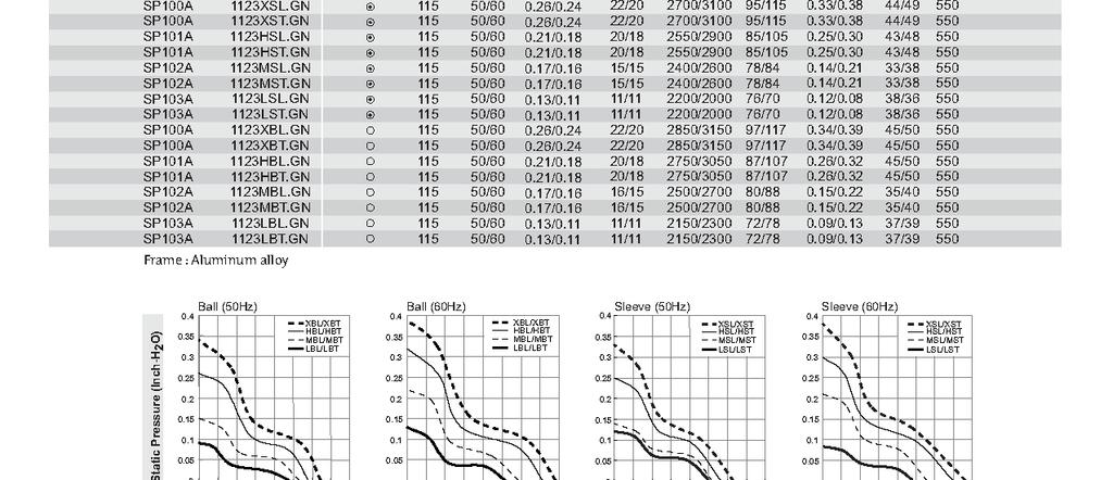
60 Thomas Industries 2660 Series, Compressors CE50 Exploded View and Parts List Thomas Industries 2660 Series, Compressors CE50 Wiring Diagram Thomas Industries 2660 Series, Compressors CE50 Troubleshooting Guide Thomas Industries 2660 Series, Compressors CHI56 Exploded View and Parts List Thomas Industries 2660 Series, Compressors CHI56 Wiring Diagram Thomas Industries 2660 Series, Compressors CHI56 Troubleshooting Guide Fans Sunon Inc. SP Series, Fans Specification Sheet Sunon Inc. SP Series, Fans Model Numbering System Regulator Norgren R07 Series Regulator Data Sheet Norgren R07 Series Regulator Installation and Maintenance Instructions D-2 Onyx/Onyx+/Onyx Ultra Instruction Manual
61 Valves ASCO Valve Inc. U8016 & US8016, Valves Open-Frame Solenoids Installation and Maintenance Instructions Onyx/Onyx+/Onyx Ultra Instruction Manual D-3
62 D-4 Onyx/Onyx+/Onyx Ultra Instruction Manual
63 Onyx/Onyx+/Onyx Ultra Instruction Manual D-5
64 D-6 Onyx/Onyx+/Onyx Ultra Instruction Manual
65 Onyx/Onyx+/Onyx Ultra Instruction Manual D-7
66 D-8 Onyx/Onyx+/Onyx Ultra Instruction Manual
67 Onyx/Onyx+/Onyx Ultra Instruction Manual D-9
68 D-10 Onyx/Onyx+/Onyx Ultra Instruction Manual
69 Onyx/Onyx+/Onyx Ultra Instruction Manual D-11
70 D-12 Onyx/Onyx+/Onyx Ultra Instruction Manual
71 Onyx/Onyx+/Onyx Ultra Instruction Manual D-13
72 D-14 Onyx/Onyx+/Onyx Ultra Instruction Manual
73 Onyx/Onyx+/Onyx Ultra Instruction Manual D-15
74 D-16 Onyx/Onyx+/Onyx Ultra Instruction Manual
75 Onyx/Onyx+/Onyx Ultra Instruction Manual D-17
76 D-18 Onyx/Onyx+/Onyx Ultra Instruction Manual
77 Onyx/Onyx+/Onyx Ultra Instruction Manual D-19
78 D-20 Onyx/Onyx+/Onyx Ultra Instruction Manual
79 Onyx/Onyx+/Onyx Ultra Instruction Manual D-21
80 D-22 Onyx/Onyx+/Onyx Ultra Instruction Manual
81 Onyx/Onyx+/Onyx Ultra Instruction Manual D-23
82 D-24 Onyx/Onyx+/Onyx Ultra Instruction Manual
83 Onyx/Onyx+/Onyx Ultra Instruction Manual D-25
84 D-26 Onyx/Onyx+/Onyx Ultra Instruction Manual
85 Onyx/Onyx+/Onyx Ultra Instruction Manual D-27
86 D-28 Onyx/Onyx+/Onyx Ultra Instruction Manual
87 Onyx/Onyx+/Onyx Ultra Instruction Manual D-29
88 D-30 Onyx/Onyx+/Onyx Ultra Instruction Manual
89 Onyx/Onyx+/Onyx Ultra Instruction Manual D-31
90 D-32 Onyx/Onyx+/Onyx Ultra Instruction Manual
91 Onyx/Onyx+/Onyx Ultra Instruction Manual D-33
92 D-34 Onyx/Onyx+/Onyx Ultra Instruction Manual
93 Onyx/Onyx+/Onyx Ultra Instruction Manual D-35
94 D-36 Onyx/Onyx+/Onyx Ultra Instruction Manual
95 Onyx/Onyx+/Onyx Ultra Instruction Manual D-37

96 D-38 Onyx/Onyx+/Onyx Ultra Instruction Manual
97 Onyx/Onyx+/Onyx Ultra Instruction Manual D-39
98 D-40 Onyx/Onyx+/Onyx Ultra Instruction Manual

99 Onyx/Onyx+/Onyx Ultra Instruction Manual D-41

100 D-42 Onyx/Onyx+/Onyx Ultra Instruction Manual
AirSep Corporation Centrox PSA Oxygen Concentrator
 Centrox PSA Oxygen Concentrator Instruction Manual MN124-1 03/11 Rev. B AirSep Corporation 260 Creekside Drive Buffalo, NY 14228-2075 USA Phone: 1-800-320-0303 Fax: (716) 691-1255 www.airsep.com Ownership
AirSep Corporation Reliant PSA Oxygen Concentrator. Instruction Manual
 AirSep Corporation Reliant PSA Oxygen Concentrator Instruction Manual MN021-1 AirSep Corporation 260 Creekside Drive Buffalo, NY 14228-2075 USA Phone: (716) 691-0202 Fax: (716) 691-1255 Ownership Data
Oxygen Concentrator. Installation and Operation Manual. ClearWater Tech, LLC. Integrated Ozone Systems
 Oxygen Concentrator Installation and Operation Manual ClearWater Tech, LLC. Integrated Ozone Systems 850-E Capitolio Way, San Luis Obispo, Ca 93401 805-549-9724 Fax: 805-549-0306 E-mail: service@cwtozone.com
AIR COMPRESSOR OPERATING INSTRUCTION AND PARTS LIST
 AIR COMPRESSOR OPERATING INSTRUCTION AND PARTS LIST OIL-LESS TYPE IMPORTANT: PLEASE READ CAREFULLY BEFORE STARTING OPERATIONS. THE CONTENTS ARE FOR GENERAL INFORMATION OF ALL THE SIMILAR MODELS. Record
453 Series Steam Heated Vaporizing Regulator
 ADI 0453A Certified ISO 9001:2000 453 Series Steam Heated Vaporizing Regulator INSTALLATION AND OPERATION INSTRUCTIONS Before Installing or Operating, Read and Comply with These Instructions Controls Corporation
NB/NBR NITROGEN BOOSTER FOR AVIATION SERVICE
 NB/NBR NITROGEN BOOSTER FOR AVIATION SERVICE INSTALLATION, OPERATION & MAINTENANCE MANUAL INTERFACE DEVICES, INC. 230 Depot Road, Milford, CT 06460 Ph: (203) 878-4648, Fx: (203) 882-0885, E-mail: info@interfacedevices.com
AND OPERATION INSTRUCTIONS
 ADI 2111-D Certified ISO 9001 MEDICAL FLOWMETER (Back Pressure Compensated Thorpe Tube) INSTALLATION AND OPERATION INSTRUCTIONS Before Installing or Operating, Read and Comply with These Instructions Controls
AC1810 / AC1810-A TECHNICAL SPECIFICATIONS. Operating Pressure psi ( kgs/cm²) [AC1810] Displacement. Net Weight
![AC1810 / AC1810-A TECHNICAL SPECIFICATIONS. Operating Pressure psi ( kgs/cm²) [AC1810] Displacement. Net Weight](/thumbs/83/88369739.jpg "AC1810 / AC1810-A TECHNICAL SPECIFICATIONS. Operating Pressure psi ( kgs/cm²) [AC1810] Displacement. Net Weight") Technical Specifications Operating Instructions Maintenance Information Troubleshooting Guide Parts Diagrams AC1810 / AC1810-A THE EVOLUTION OF PERFECTION CAUTION: Before attempting to use or service this
Technical Specifications Operating Instructions Maintenance Information Troubleshooting Guide Parts Diagrams AC1810 / AC1810-A THE EVOLUTION OF PERFECTION CAUTION: Before attempting to use or service this
AMP Oil Free Manual AMP 50-8-TC AMP 50-6-D AMP General User and Maintenance Instructions
 AMP Oil Free Manual AMP 50-8-TC AMP 50-6-D AMP 50-24 General User and Maintenance Instructions Silentaire Technology 8614 Veterans Memorial Dr. Houston, TX 77088 800-972-7668 Fax 832-327-0669 www.silentaire.com
OPERATION MANUAL NTF-60 Plus
 OPERATION MANUAL NTF-60 Plus Nitrogen Tire Filling Valve Stem Caps (Qty=200) Order P/N 436075 RTI Technologies, Inc 10 Innovation Drive York, PA 17402 800-468-2321 www.rtitech.com 035-81264-00 (Rev A)
2 GAL AIR COMPRESSOR OPERATOR S MANUAL 1/3HP/2-GALLON IMPORTANT: READ THIS OPERATOR S MANUAL BEFORE USING
 ITEM# AT01101 SKU# 207-1525 OPERATOR S MANUAL 1/3HP/2-GALLON 2 GAL AIR COMPRESSOR IMPORTANT: READ THIS OPERATOR S MANUAL BEFORE USING Toll Free Helpline: 1-888-899-0146 Versions 01 TABLE OF CONTENTS SAFETY
USER MANUAL SAVE THESE INSTRUCTIONS. For the most current manual revision, please visit our Website:
 USER MANUAL Model: PM4300 Series SAVE THESE INSTRUCTIONS For the most current manual revision, please visit our Website: www.precisionmedical.com 300 Held Drive Tel: (+001) 610-262-6090 Northampton, PA
100C Air Compressor Kit
 10010 100C Air Compressor (standard mounting bracket, CE Spec) 10014 100C Air Compressor (no leader hose or check valve, CE Spec) 10016 100C Air Compressor (with Omega Bracket, CE Spec) IMPORTANT: It is
OPERATION MANUAL NTF-15
 OPERATION MANUAL NTF-15 Nitrogen Tire Filling Valve Stem Caps (Qty=200) Order P/N 436075 RTI Technologies, Inc 10 Innovation Drive York, PA 17402 800-468-2321 www.rtitech.com 035-81235-00 (Rev B) TABLE
HAS2400 Hepa Air Scrubber
 HAS2400 Hepa Air Scrubber Diamonds Products 15 SW 40th Ave Great Bend, KS 67530 USA Toll Free: (866) 539-1694 Local: (620) 792-4542 Purchase Date: Serial Number: Purchased From: The DIAMOND HAS2400 HEPA
SSFU SUPER SPRAYFAST UNIVERSAL ADHESIVE APPLICATOR
 S S F U SSFU SUPER SPRAYFAST UNIVERSAL ADHESIVE APPLICATOR MACHINERY DIVISION OWNER S MANUAL UNIT INSTRUCTIONS Please follow all SSFU Safety Instructions. Contact your Duro Dyne Tech Service if you have
42045 Heavy Duty ADA Base Model Kit: 85/105 PSI (ADA Compressor Only) Heavy Duty ADA Base Model Kit: 110/145 PSI (ADA Compressor Only)
 Heavy Duty ADA Base Model Kit: 110/145 PSI (ADA Compressor Only)") 42045 Heavy Duty ADA Base Model Kit: 85/105 PSI (ADA Compressor Only) 42047 Heavy Duty ADA Base Model Kit: 110/145 PSI (ADA Compressor Only) 45052 Constant Duty ADA Base Model Kit: 85/105 PSI (ADA Compressor
42045 Heavy Duty ADA Base Model Kit: 85/105 PSI (ADA Compressor Only) 42047 Heavy Duty ADA Base Model Kit: 110/145 PSI (ADA Compressor Only) 45052 Constant Duty ADA Base Model Kit: 85/105 PSI (ADA Compressor
200 PSI COMPRESSORS - MODEL NUMBERS
 200 PSI COMPRESSORS - MODEL NUMBERS 380C AIR COMPRESSOR KIT PART NO. 38033 480C AIR COMPRESSOR KIT PART NO. 48043 380C 480C IMPORTANT: It is essential that you and any other operator of this product read
RIX COMPRESSORS. MICROBOOST Owner s Manual CONFIGURATION A MB-115 MB-230. November 21, 2002 APPLICABILITY [ A]
![RIX COMPRESSORS. MICROBOOST Owner s Manual CONFIGURATION A MB-115 MB-230. November 21, 2002 APPLICABILITY [ A]](/thumbs/77/74792841.jpg "RIX COMPRESSORS. MICROBOOST Owner s Manual CONFIGURATION A MB-115 MB-230. November 21, 2002 APPLICABILITY [ A]") RIX COMPRESSORS MICROBOOST Owner s Manual CONFIGURATION A MB-115 MB-230 November 21, 2002 APPLICABILITY [ A] INTRODUCTION Safety This electromechanical equipment is designed to produce high pressure gas.
RIX COMPRESSORS MICROBOOST Owner s Manual CONFIGURATION A MB-115 MB-230 November 21, 2002 APPLICABILITY [ A] INTRODUCTION Safety This electromechanical equipment is designed to produce high pressure gas.
CSA Sample Draw Aspirator Adapter Operator s Manual
 30-0951-CSA Sample Draw Aspirator Adapter Operator s Manual Part Number: 71-0367 Revision: 0 Released: 4/30/15 www.rkiinstruments.com WARNING Read and understand this instruction manual before operating
U S E R M A N U A L CAUTION. SAVE THESE INSTRUCTIONS Federal (USA) law restricts this device to sale by or on the order of a physician.
 law restricts this device to sale by or on the order of a physician.") U S E R M A N U A L 1600 SERIES OXYGEN REGULATOR 168715G (Shown) SAVE THESE INSTRUCTIONS Federal (USA) law restricts this device to sale by or on the order of a physician. 300 Held Drive Tel: (+001) 610-262-6090
U S E R M A N U A L 1600 SERIES OXYGEN REGULATOR 168715G (Shown) SAVE THESE INSTRUCTIONS Federal (USA) law restricts this device to sale by or on the order of a physician. 300 Held Drive Tel: (+001) 610-262-6090
OC4000 USER'S GUIDE I O OXYGEN CONCENTRATOR FOR VETERINARY USE ONLY. by Supera Anesthesia Innovations GLOSSARY OF SYMBOLS. : ON (power switched on)
") by Supera Anesthesia Innovations USER'S GUIDE OC4000 OXYGEN CONCENTRATOR FOR VETERINARY USE ONLY I O : ON (power switched on) : OFF (power switched off) : Class II protection : Do not expose to open flames
by Supera Anesthesia Innovations USER'S GUIDE OC4000 OXYGEN CONCENTRATOR FOR VETERINARY USE ONLY I O : ON (power switched on) : OFF (power switched off) : Class II protection : Do not expose to open flames
Workhorse-15 Oxygen Generator
 11436 Sorrento Valley Road, San Diego CA 92121 USA 858-558-0202 Fax 858-558-1915 Workhorse-15 Oxygen Generator Model No. 5719, 5727, 5735 for Domestic and International Units Part number 1432 Revision
Marschalk Model # 94000
 Marschalk Model # 94000 12-volt DC Portable oil-less Air Compressor Operation Manual 27250006 REV 1 9/13/05 Table of Contents CHAPTER 1: SYSTEM DESCRIPTION... 5 FUNCTION AND THEORY... 5 SYSTEM COMPONENTS...
IMPORTANT SAFETY INSTRUCTIONS
 IMPORTANT SAFETY INSTRUCTIONS CAUTION - To reduce risk of electrical shock: - Do not disassemble. Do not attempt repairs or modifications. Refer to qualified service agencies for all service and repairs.
GETZ EQUIPMENT INNOVATORS PART NO.: 9G59554 MODEL: MS 36 SC-R HYDROSTATIC TEST PUMP
 GETZ EQUIPMENT INNOVATORS PART NO.: 9G59554 MODEL: MS 36 SC-R HYDROSTATIC TEST PUMP LIMITED WARRANTY Getz Equipment Innovators warrants its products, and component parts of any product manufactured by
INSTALLATION MANUAL Matheson Tri-Gas Cabinet Enclosures
 INSTALLATION MANUAL Matheson Tri-Gas Cabinet Enclosures MINT-0289-XX TABLE OF CONTENTS Limited Warranty... 3 User Responsibility... 3-4 General Service... 4 Safety Precautions.... 5 Physical Dimensions..
Nidek Medical Products, Inc Mark 5 Nuvo Lite Oxygen Concentrator Service Manual
 Nidek Medical Products, Inc Mark 5 Nuvo Lite Oxygen Concentrator Service Manual Nidek Medical Products, Inc. 3949 Valley East Industrial Drive Birmingham, Alabama 35217 USA Telephone: (205) 856-7200 24-Hour
OX SCFH Oxygen Concentrator. Installation and Operation Manual
 451 Black Forest Road Hull, IA 51239 Ph: (712) 439-6880 Fax: (712) 439-6733 www.ozonesolutions.com OX-46 46 SCFH Oxygen Concentrator Installation and Operation Manual Table of Contents Cautions, Warnings
TECHNICAL DATA MAINTENANCE AIR COMPRESSOR MODEL G-1
 Dry 131h 1. DESCRIPTION The Viking Model G-1 Maintenance Air Compressor is an electric motor-driven, aircooled, single-stage, oil-less compressor. The unit is equipped with a check valve and provides a
PC1131 Electric Air Compressor
 Senco Products Inc. 8485 Broadwell Road Cincinnati, Ohio 45244 PC1131 Electric Air Compressor Operating Instructions C US 2006, 2007 by Senco Products, Inc. Warnings for the safe use of this tool are included
Oxygen Concentrator Instruction
 WARNING-Read instruction before operating this equipment Oxygen Concentrator Instruction K5BW WARNING Oxygen therapy can be hazardous in certain conditions. Seeking medical advice before using an oxygen
420C AIR COMPRESSOR KIT PART NO C AIR COMPRESSOR KIT PART NO
 420C AIR COMPRESSOR KIT PART NO. 42042 460C AIR COMPRESSOR KIT PART NO. 46043 420C 460C IMPORTANT: It is essential that you and any other operator of this product read and understand the contents of this
AIR COMPRESSOR. Failure to follow all instructions as listed below may result in electrical shock, fire, and/or serious personal injury.
 2 GALLON AIR COMPRESSOR Model: 7517 DO NOT RETURN TO STORE. Please CALL 800-348-5004 for parts and service. CALIFORNIA PROPOSITION 65 WARNING: You can create dust when you cut, sand, drill or grind materials
Tri-Safem Model I1 Regulator. INSTRUCTIONS and PARTS
 Tri-Safem Model I1 Regulator INSTRUCTIONS and PARTS USER RESPONSIBILITY This equipment will perform in conformity with the description thereof contained In this manual and accompanying labels andlor inserts
MODEL NUMBER: PSI AIR SOURCE KIT 200 PSI Compressor on 2.0 Gallon 200 PSI Air Tank
 IMPORTANT SAFETY INSTRUCTIONS CAUTION - To reduce risk of electrical shock or Electrocution: MODEL NUMBER: 20008 200 PSI AIR SOURCE KIT 200 PSI Compressor on 2.0 Gallon 200 PSI Air Tank IMPORTANT: It is
SPECIFICATIONS Type: Twin stack, single phase Tank: 4 gallon Air Output: PSI; PSI Max PSI: 125 PSI HP: 1.
 2 GALLON TWIN STACK AIR COMPRESSOR Model: 9526 DO NOT RETURN TO STORE. Please CALL 800-348-5004 for parts and service. CALIFORNIA PROPOSITION 65 WARNING: You can create dust when you cut, sand, drill or
Model ASSEMBLY and OPERATING INSTRUCTIONS
 QUICK CHANGE AIR BRUSH KIT Model 93506 ASSEMBLY and OPERATING INSTRUCTIONS Due to continuing improvements, actual product may differ slightly from the product described herein. 3491 Mission Oaks Blvd.,
Nidek Medical Products, Inc Mark 5 Nuvo Lite Oxygen Concentrator Service Manual
 Nidek Medical Products, Inc Mark 5 Nuvo Lite Oxygen Concentrator Service Manual Nidek Medical Products, Inc. 3949 Valley East Industrial Drive Birmingham, Alabama 3527 USA Telephone: (205) 856-7200 24-Hour
User s Guide Temperature Sensor Converter TSC-599
 User s Guide Temperature Sensor Converter TSC-599 ILX Lightwave Corporation 31950 Frontage Road Bozeman, MT, U.S.A. 59715 U.S. & Canada: 1-800-459-9459 International Inquiries: 406-556-2481 Fax 406-586-9405
400H HARDMOUNT AIR COMPRESSOR KIT PART NO H HARDMOUNT AIR COMPRESSOR KIT PART NO
 400H HARDMOUNT AIR COMPRESSOR KIT PART NO. 40042 450H HARDMOUNT AIR COMPRESSOR KIT PART NO. 45042 400H 450H IMPORTANT: It is essential that you and any other operator of this product read and understand
Compact Triple Cabinet Outlet Station Model Installation and Operating Instructions
 Compact Triple Cabinet Outlet Station Model 6258-1 Installation and Operating Instructions The Porter Compact Triple Outlet Station (6258-1) provides a quick, safe, and reliable method of connection to
Cocoa Patio Pond with Lit Spillway
 Cocoa Patio Pond with Lit Spillway REMINDER CALL 1-888-755-5641 BEFORE RETURNING TO STORE. PACKAGE CONTENTS ITEM # GQSPPB/GQSPPW Questions, problems, missing parts? Before returning to your retailer, call
97C COMPRESSOR KIT 12V PART NO C COMPRESSOR KIT 24V PART NO C COMPRESSOR KIT PART NO
 97C COMPRESSOR KIT 12V PART NO. 00097 97C COMPRESSOR KIT 24V PART NO. 02497 98C COMPRESSOR KIT PART NO. 00098 97C 98C IMPORTANT: It is essential that you and any other operator of this product read and
623 Series Dome Load Regulators
 ADI 3202C Certified ISO 9001 623 Series Dome Load Regulators INSTALLATION AND OPERATION INSTRUCTIONS This Equipment is intended to be installed and operated by trained personnel. Before Installing or Operating,
Freedom8 ShoeBox Compressor Manual
 Freedom8 ShoeBox Compressor Manual Warning!! This product is not a toy! Use or misuse can cause severe injury or death! Use only with adult supervision. This unit is only to be used with tanks, hoses and
MODEL Maverick Heavy Duty Aerosol Compressor Operator s Manual
 MODEL 50012 Maverick Heavy Duty Aerosol Compressor Operator s Manual This page left blank intentionally CONTENTS Page No. INSPECTION... 1 GENERAL INFORMATION... 1 SAFETY PRECAUTIONS... 2 BASIC OPERATING
MODEL NUMBER: M20005 AIR SOURCE KIT. 30% Duty Compressor on. 2.0 Gallon Air Tank SAVE THIS MANUAL FOR FUTURE REFERENCE
 MODEL NUMBER: M20005 AIR SOURCE KIT 30% Duty Compressor on 2.0 Gallon Air Tank SAVE THIS MANUAL FOR FUTURE REFERENCE USER MANUAL IMPORTANT SAFETY INSTRUCTIONS CAUTION - To reduce risk of electrical shock
Table of Contents. Operating Instructions. Resource v.2 Conserving Regulator
 Operating Instructions Table of Contents Resource v.2 Conserving Regulator Safety Information Device Precautions Introduction Product Features Product Specifications Feature Illustrations Set Up Usage
444C DUAL PERFORMANCE VALUE PACK
 (Chrome) PART NO. 44432 IMPORTANT: It is essential that you and any other operator of this product read and understand the contents of this manual before installing and using this product. SAVE THIS MANUAL
200 PSI FAST-FILL AIR SOURCE KIT
 200 PSI FAST-FILL AIR SOURCE KIT 55% Duty Compressor on 2.0 Gallon Air Tank PART NO. 20007 IMPORTANT: It is essential that you and any other operator of this product read and understand the contents of
200 PSI HIGH-FLOW AIR SOURCE KIT
 200 PSI HIGH-FLOW AIR SOURCE KIT 50% Duty Compressor on 2.0 Gallon Air Tank PART NO. 20008 IMPORTANT: It is essential that you and any other operator of this product read and understand the contents of
NewLife Elite / NewLife Oxygen Concentrator Service Manual
 0459 NewLife Elite / NewLife Oxygen Concentrator Service Manual AirSep is a registered trademark of AirSep Corporation. NewLife Elite and NewLife are registered trademarks of AirSep Corporation. MN105-1
Operating Manual. Model 25200B/25202B Refrigerant Recovery Unit. (Not for use in automotive R-134a applications)
") Operating Manual Model 25200B/25202B Refrigerant Recovery Unit (Not for use in automotive R-134a applications) ROBINAIR Refrigerant Recovery Unit Model: 25200B /25202B Series Type of Equipment: Recovery
Operating Manual Model 25200B/25202B Refrigerant Recovery Unit (Not for use in automotive R-134a applications) ROBINAIR Refrigerant Recovery Unit Model: 25200B /25202B Series Type of Equipment: Recovery
250C-IG COMPRESSOR KIT 12V PART NO C-IG COMPRESSOR KIT 24V PART NO
 250C-IG COMPRESSOR KIT 12V PART NO. 25050 250C-IG COMPRESSOR KIT 24V PART NO. 25058 IMPORTANT: It is essential that you and any other operator of this product read and understand the contents of this manual
Nitrogen Supply System
 ATMOSCOPE Nitrogen Supply System NS500 Users Guide Copyright 2001 EDSYN, INC. ATMOSCOPE Nitrogen Supply Systems TABLE OF CONTENTS Introduction............................. 3 General Information.......................
Compact Triple Cabinet Outlet Station Model B Installation and Operating Instructions
 PORTER Parker Hannifin Corporation Porter Instrument Division 245 Township Line Rd. P.O. Box 907 Hatfield, PA 19440-0907 USA (215) 723-4000 / fax (215) 723-5106 Compact Triple Cabinet Outlet Station Model
High Pressure Inlet Kits for CONCOA BlendMites and BlendMasters
 ADI 3210-A ADI 3210-A Certified ISO 9001 Certified ISO 9001 High Pressure Inlet Kits for CONCOA BlendMites and BlendMasters Warning: An appropriately sized pressure relief device downstream of the regulator
2 GALLON TWIN STACK AIR COMPRESSOR W/ HOSE REEL
 2 GALLON TWIN STACK AIR COMPRESSOR W/ HOSE REEL Model: 52024 CALIFORNIA PROPOSITION 65 WARNING: You can create dust when you cut, sand, drill or grind materials such as wood, paint, metal, concrete, cement,
Technical Information
 Technical Information Installation, Operation, Installation, Operation and Maintenance and Maintenance Manual Manual Balston Model 75700-K728 Nitrogen Generator Figure 1-75700-K728 Overall Dimensions These
RK-IR Sample Draw Aspirator Adapter Operator s Manual
 30-0951RK-IR Sample Draw Aspirator Adapter Operator s Manual Part Number: 71-0018RK Revision: A Released: 6/2/10 www.rkiinstruments.com Product Warranty RKI Instruments, Inc. warrants gas alarm equipment
450P AUTOMATIC PORTABLE COMPRESSOR EXTREME SERIES
 EXTREME SERIES PART NO. 45043 IMPORTANT: It is essential that you and any other operator of this product read and understand the contents of this manual before installing and using this product. SAVE THIS
OC4000 USER'S GUIDE I O OXYGEN CONCENTRATORS OXYGEN CONCENTRATOR FOR VETERINARY USE ONLY GLOSSARY OF SYMBOLS. : ON (power switched on)
") OXYGEN CONCENTRATORS USER'S GUIDE OC4000 OXYGEN CONCENTRATOR FOR VETERINARY USE ONLY I O : ON (power switched on) : OFF (power switched off) : Class II protection : Do not expose to open flames GLOSSARY
OXYGEN CONCENTRATORS USER'S GUIDE OC4000 OXYGEN CONCENTRATOR FOR VETERINARY USE ONLY I O : ON (power switched on) : OFF (power switched off) : Class II protection : Do not expose to open flames GLOSSARY
U S E R M A N U A L. Model: PM4300 Series SAVE THESE INSTRUCTIONS
 U S E R M A N U A L Model: PM4300 Series (PM4351 Shown) SAVE THESE INSTRUCTIONS CAUTION Federal (USA) law restricts this device to sale by or on the order of a physician. 300 Held Drive Tel: (+001) 610-262-6090
3 GALLON, OILLESS PANCAKE COMPRESSOR INSTRUCTIONS. Item #31289
 3 GALLON, OILLESS PANCAKE COMPRESSOR INSTRUCTIONS Item #31289 The EASTWOOD 3 GALLON, OILLESS PANCAKE COMPRESSOR, with an Integral Air Regulator, efficiently supplies all compressed air requirements for
250C-IG COMPRESSOR KIT 12V PART NO C-IG COMPRESSOR KIT 24V PART NO
 250C-IG COMPRESSOR KIT 12V PART NO. 25050 250C-IG COMPRESSOR KIT 24V PART NO. 25058 IMPORTANT: It is essential that you and any other operator of this product read and understand the contents of this manual
CS150 CAP STAPLER OWNER S MANUAL
 Operation Revised 6/2013 www.stingerworld.com CS150 CAP STAPLER OWNER S MANUAL! Maintenance Safety Warranty PLEASE READ! This manual contains important information about product safety. WELCOME TO STINGER
450P- RV AUTOMATIC PORTABLE COMPRESSOR EXTREME SERIES
 450P- RV AUTOMATIC PORTABLE COMPRESSOR EXTREME SERIES PART NO. 45053 IMPORTANT: It is essential that you and any other operator of this product read and understand the contents of this manual before installing
R E D I C O N T R O L S
 R E D I C O N T R O L S Operation & Maintenance Manual Portable Service Purger for Low Pressure Chillers Model: PSP-LP-1B For Refrigerants R-11, R-113, R-114 & R-123 & Other Similar Refrigerants File Literature
In Vivo Scientific, LLC INSTRUCTION MANUAL
 CO 2 Controller In Vivo Scientific, LLC INSTRUCTION MANUAL CONTENTS CONTENTS...1 ABOUT THIS MANUAL...2 INTRODUCTION...2 Cautions and Warnings...2 Parts List...2 Unpacking...2 INSTRUMENT DESCRIPTION...3
Budget Range Operators Handbook
 Budget Range Operators Handbook BAMBI AIR COMPRESSORS LTD 152 Thimble Mill Lane Heartlands Birmingham B7 5HT United Kingdom Tel: 0121 322 2299 Fax: 0121 322 2297 Email: sales@bambi-air.co.uk www.bambi-air.co.uk
Interface Devices, Inc. Hydraulic Mini Mule
 Interface Devices, Inc. Hydraulic Mini Mule INSTALLATION, OPERATION & MAINTENANCE MANUAL IMPORTANT! FILE THIS MANUAL IN A SAFE PLACE FOR FUTURE SERVICE & PARTS NEEDS ALWAYS REFERENCE THE SERIAL NUMBER
ULTRA QUIET & OIL FREE
 ULTRA QUIET & OIL FREE AIR COMPRESSOR OwnER'S MAnUAL CALIFORnIA AIR TOOLS 20040C 4.0 HP 20 gal. WWW.CALIFORNIAAIRTOOLS.COM Customer Support 1-866-409-4581 TAbLe OF CONTeNTS INTROduCTION IntroductIon 2
INSTRUCTIONS FOR MODELS SG3897 AND SG3898 CROSS PURGE ASSEMBLIES
 INSTRUCTIONS FOR MODELS SG3897 AND SG3898 CROSS PURGE ASSEMBLIES THIS BOOKLET CONTAINS PROPRIETARY INFORMATION OF ADVANCED SPECIALTY GAS EQUIPMENT CORP. AND IS PROVIDED TO THE PURCHASER SOLELY FOR USE
USER MANUAL SAVE THESE INSTRUCTIONS. 300 Held Drive Tel: (+001) Northampton, PA USA Fax: (+001) ISO Certified
 Northampton, PA USA Fax: (+001) ISO Certified") USER MANUAL Model: PM4300 Series (PM4351 Shown) SAVE THESE INSTRUCTIONS Federal (USA) law restricts this device to sale by or on the order of a physician. 300 Held Drive Tel: (+001) 610-262-6090 Northampton,
USER MANUAL Model: PM4300 Series (PM4351 Shown) SAVE THESE INSTRUCTIONS Federal (USA) law restricts this device to sale by or on the order of a physician. 300 Held Drive Tel: (+001) 610-262-6090 Northampton,
400C & 450C DUAL PERFORMANCE VALUE PACKS
 (Chrome) PART NO. 40013 (Silver) PART NO. 45012 (Chrome) PART NO. 45013 IMPORTANT: It is essential that you and any other operator of this product read and understand the contents of this manual before
Certified ISO 9000 INSTALLATION AND OPERATION INSTRUCTIONS. Before Installing or Operating, Read and Comply with These Instructions
 ADI 1219-M Certified ISO 9000 1600 Series Dual-Range Flowmeters INSTALLATION AND OPERATION INSTRUCTIONS Before Installing or Operating, Read and Comply with These Instructions Controls Corporation of America
2 Gallon Air Compressor
 Table of Contents Topic Page 2 Gallon Air Compressor Safety Guidelines-Definitions 4 Hazard Warnings 5 Air Compressor 15 Precautions 15 Basic Air Compressor Components 16 Assembling the Air Compressor
Installation Instructions Air Compressor Part # 2780, 2781
 Note: It is essential that the operator of this product read and understand the contents of this manual before installing and using this product. Parts Included Qty Parts Included Qty Compressor 1 Coil
SERVICE MANUAL MODEL BA050BMST BREATHING AIR PANEL
 www.modsafe.com SERVICE MANUAL MODEL BA050BMST BREATHING AIR PANEL WARNING: Do not attempt to operate this equipment without first reading and understanding the service manual enclosed with this device.
AIR INLINE METAL SHEAR
 AIR INLINE METAL SHEAR ASSEMBLY and OPERATING INSTRUCTIONS 3491 Mission Oaks Blvd. / Camarillo, CA 93011 Copyright 1997 by Harbor Freight Tools. All rights reserved. No portion of this manual or any artwork
Vapotherm Q50 Compressor. Instructions for Use
 Vapotherm Q50 Compressor Instructions for Use Contents Quick Start Guide...2 Intended Use...3 Indications, Warnings and Cautions...4 Primary Indications...4 Contraindications...4 Warnings and Cautions...4
24L OIL FREE AIR COMPRESSOR MODEL NO: TIGER 7/250 PART NO: OPERATION & MAINTENANCE INSTRUCTIONS LS10/13
 24L OIL FREE AIR COMPRESSOR MODEL NO: TIGER 7/250 PART NO: 2244030 OPERATION & MAINTENANCE INSTRUCTIONS LS10/13 INTRODUCTION Thank you for purchasing this product. Before attempting to use this product,
Portable Compressed CO 2 Regulator
 Portable Compressed CO 2 Regulator 99901 Operating Instructions Distributed exclusively by Harbor Freight Tools. 3491 Mission Oaks Blvd., Camarillo, CA 93011 Visit our website at: http://www.harborfreight.com
INSTRUCTIONS FOR MODEL SG6500 GAS HEATERS
 INSTRUCTIONS FOR MODEL SG6500 GAS HEATERS THIS BOOKLET CONTAINS PROPRIETARY INFORMATION OF ADVANCED SPECIALTY GAS EQUIPMENT CORP. AND IS PROVIDED TO THE PURCHASER SOLELY FOR USE IN CONJUNCTION WITH MODEL
User Instruction Manual
 User Instruction Manual 4500 psi Air Compressor Ver 2, 1.18 Contents Parts Included...3 Assembly Instructions...3-5 Operation Instructions...6-7 Oil Change Intervals...8 Air Filter Replacement...9 Setting
170-CG Feed Unit SPONGE-JET USER MANUAL. Sponge-Jet, Inc. (USA) 14 Patterson Lane Newington, NH
 14 Patterson Lane Newington, NH") SPONGE-JET 170-CG Feed Unit USER MANUAL Sponge-Jet, Inc. (USA) 14 Patterson Lane +1-603-610-7950 Newington, NH 03801 www.spongejet.com AUGUST 2014, Sponge-Jet 170-CG User Manual - REV A / DOC: M-MKTG-002ENG
SPONGE-JET 170-CG Feed Unit USER MANUAL Sponge-Jet, Inc. (USA) 14 Patterson Lane +1-603-610-7950 Newington, NH 03801 www.spongejet.com AUGUST 2014, Sponge-Jet 170-CG User Manual - REV A / DOC: M-MKTG-002ENG
Operating Instructions for BAIR22-6 AIR-POWERED CRIMPING TOOL
 Operating Instructions for BAIR22-6 AIR-POWERED CRIMPING TOOL Read and understand all of the instructions and safety information in this manual before operating or servicing this tool. Table of Contents
MODEL NUMBER: P-A AUTOMATIC PORTABLE COMPRESSOR
 MODEL NUMBER: 45043-450P-A AUTOMATIC PORTABLE COMPRESSOR IMPORTANT: It is essential that you and any other operator of the product read and understand the contents of this manual before installing and
with O 2 Controller Instruction Manual
 14500 Coy Drive, Grass Lake, Michigan 49240 734-475-2200 E-mail: sales@coylab.com www.coylab.com Hypoxic Cabinets (In-Vivo / In-Vitro) with O 2 Controller Instruction Manual Index Page Warranty 2 Warnings
TECHNICAL INFORMATION
 TECHNICAL INFORMATION Installation, Operation, and Maintenance Balston 75-96 and 75-98 Nitrogen Generation System Tower Pressure Gauge 5'-1" 3'-6" 7'-4" 6'-10 1/2" PLAN VIEW Figure 1 - Balston 75-96 and
Pressure Relief Valve Instruction Manual
 CVR3-M0_062017 Pressure Relief Valve Instruction Manual MODEL: CVR3 SFA Companies 10939 N. Pomona Ave. Kansas City, MO 64153 Tel: 888-332-6419 * Fax: 816-448-2142 E-mail: sales@bvahydraulics.com Website:
INSTRUCTIONS PARTS LIST
 3066V-E INSTRUCTIONS PARTS LIST INSTRUCTIONS! This manual contains important warnings and information. READ AND KEEP FOR REFERENCE. AQ Poppet Color Valve (3066-41-00A) 304 Stainless Steel Body Autoquip,
APCO ASU-SCAV & ASU-CAV SINGLE BODY COMBINATION AIR VALVES
 APCO ASU-SCAV & ASU-CAV SINGLE BODY COMBINATION AIR VALVES Instruction D12039 December 2015 Instructions These instructions provide installation, operation and maintenance information for the. They are
J Air and Water Kit Instructions Part# 02584
 J Air and Water Kit Instructions Part# 02584 Unpacking Please open and inspect your package upon receipt. Your package was packed with great care and all the necessary packing materials to arrive to you
TECHNICAL INFORMATION
 TECHNICAL INFORMATION Installation, Operation, and Maintenance Balston Model 75-77 Nitrogen Generator Figure 1-75-77 Overall Dimensions These instructions must be thoroughly read and understood before
Index Table. Model 794. Installation, Operating and Maintenance Instructions
 CLOCKWISE MANUAL MAKING INTO CCW TABLE Index Table Model 794 Installation, Operating and Maintenance Instructions Black & Webster Products Division 545 Hupp Ave. P.O. Box 831, Jackson, Michigan 49204 2009
OPERATOR S MANUAL 1.5 HP/6-GALLON 6 GAL AIR COMPRESSOR IMPORTANT: READ OPERATOR S MANUAL BEFORE USING. Toll Free Helpline:
 ITEM# 0306 SKU# 07-55 OPERATOR S MANUAL.5 HP/6-GALLON 6 GAL AIR COMPRESSOR IMPORTANT: READ OPERATOR S MANUAL BEFORE USING Toll Free Helpline: -888-899-06 VY03A36669 TABLE OF CONTENTS Specifications------------------------------------------------------------------------------------------------
Protocol Switchover Station
 ADI 3215-B Certified ISO 9001 Protocol Switchover Station INSTALLATION AND OPERATION INSTRUCTIONS Before Installing or Operating, Read and Comply with These Instructions Controls Corporation of America
GETZ EQUIPMENT INNOVATORS RECOVERY SYSTEM CLEAN AGENT FE-36 / HALOTRON 1 PART NO. 4G59751 OPERATIONS MANUAL
 GETZ EQUIPMENT INNOVATORS CLEAN AGENT FE-36 / HALOTRON 1 PART NO. 4G59751 OPERATIONS MANUAL GETZ EQUIPMENT INNOVATORS PEKIN, ILLINOIS, U.S.A. PHONE: (888) 747-4389 FAX: (309) 495-0625 Limited Warranty