Troxler Electronic Laboratories, Inc.
|
|
|
- Polly Leonard
- 5 years ago
- Views:
Transcription

1 TROXLER MODELS BASIC GAUGE OPERATIONS Troxler Electronic Laboratories, Inc Cornwallis Road P.O. Box Research Triangle Park, NC Phone: TROXLER Outside the U.S.A.: Fax: PN


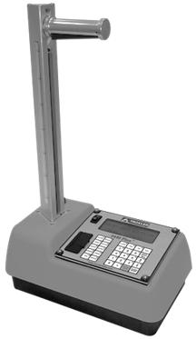
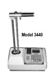

2 Model 3440 Plus T* G R R 2
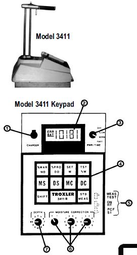
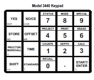
3 I. DAILY STANDARD COUNT It is important that a current and valid standard count be performed and retained in the gauge s memory in order for measurement results to be reliable. A. 10 MINUTE WARM-UP: Turn the gauge on 10 minutes before taking a standard count to allow the systems to stabilize. B. SET-UP FOR STANDARD COUNT: With the gauge in the safe or shielded position and firmly seated on the standard block, follow these precautions: At least 100 pcf material (1600 kg/m 3 ) under standard block. No large vertical objects (walls, heavy equipment, etc.) within 10 ft. (3m). No other nuclear sources within 30 ft. (10m). The keypad end of the gauge is against the metal butt plate. (For 4640, place gauge on air gap spacer with 2 posts at the handle end of the gauge. The gauge and spacer are seated on the reference plate with the plate handle toward the operator.) After beginning the standard count take a small step away from the gauge (approx. 1 meter) to reduce exposure and to not influence the count. C. TAKE A STANDARD COUNT: 1) Model 3401: Set the power/time switch to the slow (4-minute) count time and press the <Start> button. 2) Model 3411-B: Set the power/time switch to the slow (4-minute) count time and press <Shift> & <std/measure> keys. 3) Model 3430: Press the <STD> key, then the <Yes> key. Press <Start>. 4) Model 3440: Press the <STANDARD> key, and then the <Yes>key twice. 5) Model 3450: Press the <STANDARD> key, and then press <1>. Check the gauge position and press <Enter>. 6) Model 3440 Plus: Press the <STD> key. Choose <Yes>. Be sure gauge is placed properly on the standard block. Press <Start>. 7) Model 4640: Press the <STD> key, and then press <Yes>. Check gauge position then press <Enter>. 3
4 D. CHECK AND RECORD STANDARD COUNT: (The 3401, 3411 and 3430 require a standard count log to be kept by the operator. Before 4 standard counts have been taken, the factory supplied DS, MS, DS1, & DS2 can be used.) 1) Model 3401: The err symbol will disappear. Set the display switch on density to view the DS and on moisture to view the MS. Record these counts in the standard count log. The DS should be within 1% and MS within 2% of the average of the previous 4 standards. The new standards can also be compared to the factory calibration standard counts. They should be within 2% of the density standard count and within 4% of the moisture standard count on the factory calibration data sheet. 2) Model 3411-B: The err symbol will disappear and the moisture and density counts can be displayed by pressing MS and DS respectively. Record these counts in the standard count log; they will only remain in memory until the gauge is turned off. The DS should be within 1% and the MS within 2% of the average of the previous 4 standards. 3) Model 3440 / 3440 Plus: After count completion, the gauge will display the MS (moisture standard) and the DS (density standard). The P or F displayed following these numbers indicates whether or not the counts fall within the acceptable limits. The DS should be within 1% and the MS within 2% of the average of the previous 4 standard counts. 4) Model 3430: After the count is complete the gauge displays DS (density standard) and MS (moisture standard). Record these counts in the standard count log. Compare these standard counts to the average of the previous 4 counts. The DS should be within 1% and the MS within 2% of the average of the previous 4 standard counts. 5) Model 3450: After count completion the gauge will display the MS (moisture standard) and the DS1 and DS2 (density standards for systems 1 and 2) along with a P or F indicating if the counts fell within the acceptable limits. These counts are compared to the average of the previous 4 counts. The tolerance is based on a 1% variance for the DS and a 2% variance for the MS. After accepting the standard count the gauge will ask you to calibrate the depth strip by placing the rod in backscatter and pressing enter. 6) Model 4640: After the count is complete the DS1 and DS2 (density standard for system 1 and 2) counts are displayed along with a P or F indicating if the standard count fell within the acceptable limits. These counts are compared to the average of the previous 4 standard counts. The tolerance is based on a 1% variance for system 1 and a 1.2% variance for system 2 counts. 4
5 II. TAKING MEASUREMENTS ON SOILS DIRECT TRANSMISSION A. SITE PREPARATION: Using the scraper plate, smooth out the test surface and place the scraper plate on the prepared test surface. Put the drill rod through the extractor tool, then through the scraper plate guide. Securing the scraper plate with on foot, use a hammer to drive the drill rod into ground to the appropriate depth (note the marks on the rod at 2 intervals). Use the extractor tool to remove the rod from the ground with your foot remaining on the plate. Mark around the corners of the plate with the drill rod. Remove the scraper plate. Position the gauge within the outline of the scraper plate. Release the trigger in the handle and lower the source rod to the desired testing depth. Pull the gauge in the direction of the keypad to insure that the source rod is snug against the wall of the hole. This procedure reduces any exposure to the source rod by placing it directly in the hole. NOTE: Backscatter mode may be used on soil materials also if the lift thickness is approximately 4 or if the material cannot be drilled with the drill rod. B. MEASUREMENT: 1) Model 3401: Set the power/time switch to the norm, or one minute count time. Press the start button. After one minute, calculate your moisture and density count ratios by dividing the counts just taken by the standard counts taken in part 1. Look up the moisture and density values (for the count rations just calculated) on the gauge s calibration chart according to the depth of the measurement. 2) Model 3411-B: Set the power/time switch to norm, or one-minute count time. Set the depth switch to the same depth as the source rod. To set the target density value, hold the shift key and press the set/m key. The value of pcf (2000kg/m3) will display until it is changed. Set the +/- switch to the appropriate symbol (+ to go up, and - to go down) and press both shift & set. When shift is released, the number will change. Remember that this target number should be changed as the material being tested changes. To begin the test, press the std/meas key. After one minute, obtain density and moisture values by pressing the WD (wet density), DD (dry density), M (moisture), %M (percent moisture), and the %PR. %PR compares the gauge read DD to the proctor value, or target DD derived from the laboratory, which is placed in gauge memory before the test is taken. 3) Model 3430: Press the time key and scroll up or down to choose the desired length of the test (recommend 1 min.). Press the depth key. To select the desired depth of the test being taken use the up or down arrows. Press the MA/PR key and scroll to select PR to indicate the use of soils mode or MA to indicate the use of asphalt mode. Yes allows you to enter the proctor value using the arrow keys. Press enter. Lower the source rod and press the start key. After the count time has elapsed, the measurement results will be displayed. Use the up or down arrows to view the remaining results. 4) Model 3440: Press the shift and mode keys and follow the display to select the soil mode. Press the time key to set the desired count time (recommend 1 min.). If desired enter the target dry density (Proctor) by pressing the proctor/marshall key and follow the display instructions. Lower the source rod and press the start/enter key. If the automatic depth function is enabled, the correct depth of the source rod will be displayed. Otherwise the 5
6 depth will be entered manually. After the count time is complete, the measurement results will be displayed. This data can be stored for later use if a project number has been entered. 5) Model 3450: Press the mode key and choose 1 for the soil mode. Press the time key and choose 2 for the 1 minute count time. If desired, set the Proctor target density by pressing the target key and choosing 1 for Proctor. Enter either a stored value or a new laboratory derived value. Lower the source rod and press the start key. The depth of the source rod will automatically be displayed if it is in automatic mode, but will need to be entered if in manual mode. After the count time the measurement results will display. 6) Model 3440Plus: Press the mode key and choose 2 for the soil mode. Press the Setup key and choose 1 to choose the count time, then press 2 to select the recommended 1 min time. If desired, set the Proctor target density by pressing the target key and choosing 2 for Proctor. Enter either a stored value (press 1-4) or a new laboratory derived value (press 5). Lower the source rod and press the start key. The depth of the source rod will automatically be displayed if it is in automatic mode, but will need to be entered if in manual mode. After the count time the measurement results will display. 7) Model 4640: This model is not used on soil materials; it does not have a moisture source. C. DEPTH OF MEASUREMENT: The density depth of measurement is simply the depth at which the source rod is placed; with the exception of backscatter mode (this is approximately 4 ) and thin-layer mode (this depth is determined by the operator). The moisture depth of measurement is determined by the moisture (or Hydrogen) content of the material being tested. This depth can be determined by the following formula: Moisture Depth of Measurement (in inches) = 11 [0.17 (M)]; (in mm) =280 [0.27 x (M)] D. MOISTURE CORRECTION: (where M = the gauge moisture reading in pcf or kg/m3, not %M) In soils with considerable hydrogen other than water and/or significant concentrations of neutron absorbing elements, gauge moisture readings must be compared to oven dried samples to establish a correction factor. (Those hydrogenous materials include; gypsum, lime, mica, organics, cement, fly ash, coal, phosphates, etc. and neutron absorbers include; boron, cadmium, lithium, salt, iron oxide, etc.) Take four or more gauge/oven-dry sample pairs as follows; perform and record a 1 min. gauge measurement, then collect a soil sample from the same spot, keeping in mind the gauge s depth of measurement. Repeat four or more times in locations with similar moisture content. Seal the soil sample as to not lose any moisture. Find the true moisture content of the samples by oven drying. Average the values from all locations and perform the following calculations. 1. Model 3401: Calculate the moisture in PCF from the oven dry by: %M oven dry x WD M oven dry = %M oven dry Where WD = wet density Correction factor = M oven dry M (perform this for each sample site) NOTE: Do not use the %M value for this calculation. This correction is best made and used near optimum moisture and compaction. Be sure to note the plus/minus sign. 6
7 2. Model 3411-B: Make sure the gauge Moisture Correction knobs are set at 00 when taking gauge reading/soil sample pairs. Calculate correction factor using averaged values above by: Correction Factor (K) = %M oven dry - %M gauge %M gauge x 1000 Dial this number along with the sign on the gauge s Moisture Correction knobs to correct from apparent to true moisture for a soil type regardless of DD, WD, and moisture content. 3. Model 3430: Calculate the correction factor by using the averaged values and the formula: %M oven dry - %M gauge Correction Factor (K) = %M gauge x 1000 Press the special key, and then press the down arrow 1 time to access the offset function. Press the down arrow 1 time to choose moisture and press enter. Press yes and enter the K factor. 4. Model 3440: This gauge calculates the correction (K) factor as long as the %M oven-dry and %M gauge are entered. Press the offset key, then 2, then Yes. Press yes again and the 1 to be able to enter the %M true (oven-dry) and the %M gauge. Press 1 and input the %M ovendry (true) averaged above. Press 2, then choose 2 and follow the instructions to take 4 measurements at the sites where samples were taken. After both values are entered, the calculation of K is done and this factor may be stored. 5. Model 3450: This gauge calculates the correction (K) factor as long as the %M oven-dry (true) and %M gauge are entered. Press the offset key and press 2, and then choose 3. The 3450 then allows you to choose a stored offset (already entered), a gauge derived offset (determined by taking readings), or a keypad entry offset (tests already taken are averaged, the K factor is calculated and entered manually). Choose 3 for keypad entry and enter the K factor derived from the formula: K = %M(true) - %M (gauge) x 1000 ( %M (gauge ) ) Choose 2 for gauge derived offset and press 1 to measure moisture. Follow the instructions to take readings on the soil requiring an offset. To enter true moisture later (after returning to lab) press 1; to enter true moisture, now press 2 and follow gauge instructions, when the true moisture is to be entered later. The K factor will then be displayed and may be stored. 6. Model 3440 Plus: This gauge calculates the correction (K) factor as long as the %M ovendry (true) and %M gauge are entered (Manual entry). Press the offset key and press 2; then choose 5 for a new offset or select a previously stored offset if desired. The gauge then allows you to choose a manual entry offset (data has already been collected). Or a gauge derived offset (determined by taking readings and comparing to a known moisture value). Gauge derived is used if the true moisture can be determined quickly at the site (stove dry, Speedy, etc.) For manual entry, choose 1 and enter the data as prompted. This is generally done after the gauge readings are performed and recorded and a sample is taken to the lab and analyzed. After all data is known the K factor can be calculated by the gauge. 7
8 E. TRENCH CORRECTION: All nuclear soils gauges are sensitive to any moisture (hydrogen) in the neighborhood of the gauge. Therefore it is necessary to compensate for the effe3ct on gauge moisture readings any time the gauge is used in a trench, next to a retaining wall, by the wall of a building, or near any large vertical obstacle. In every case, this compensation involves taking a moisture count (not a standard count) with the gauge placed on the standard block at the trench test site and comparing the count obtained to the standard count taken earlier that day. 1. Model 3401: Subtract the daily moisture standard count (MS) from the moisture count (MC) taken with the gauge on the standard block in the trench. Subtract this difference from the gauge moisture count taken in trench measurements. 2. Model 3411: Take the measurement in the trench on the standard block and subtract the MS from the MC. Now dial this difference into the gauge by setting it on the moisture correction knobs. While holding down the shift key, press MC; the difference should appear on the LCD screen. This value will then be subtracted from the moisture count until either a) the gauge is turned off or b) the trench correction is zeroed by setting the moisture correction knobs to 00 and pressing shift, MC; the gauge will display all zero s to indicate that the trench correction factor has been removed from gauge memory. 3. Model 3430: After taking a daily standard count, take a 4 min. test in the trench with the gauge on the standard block. Subtract the daily standard counts from the trench counts. Trench Density Count (Dens. Const.) = (DC trench DS) Trench Moisture Count (Moist. Const.) = (MC trench MS) Press the special key, choose the offset option by pressing the down arrow 1 time, and choose trench. The gauge will then request the Dens. Const. And the Moist. Const. To scroll through the numerals, press the up and down arrows. 4. Model 3440: Press offset and choose #3. Press yes 2 times to perform a new offset. Place the gauge on the block in the trench and begin the 1 minute count by pressing start. The Density and Moisture Trench Offset constants will be calculated, enabled and stored. 5. Model 3450 & 3440 Plus: Press the offset key and then choose 3. Press 3 to change the offset. Place the gauge on the block in the trench where measurements will be performed and press the start key to begin the count. Press yes to enable the new trench offset that has been calculated. 6. Model 4640: This gauge does not have a moisture source, no trench offset is needed. 8
9 F. DENSITY CORRECTION: A density correction factor may be used when the material being tested varies in density from the normal range of soils (90 to 170 PCF/1450 to 2720 kg/m3) or if the material composition varies from average soil/asphalt on which the factory calibration is based. A comparison may be made between an accurately controlled sand cone and nuclear testing. Also cores drilled from compacted asphalt can be correlated to nuclear density readings. The average difference of at least 4 tests should be used in the calculations. 1. Model 3401 and 3411-B: The correction factor obtained should be applied by the operator as a plus or minus figure to the measure wet density. i. Model 3430: Press special and press the down arrow 1 time, then enter. Press yes. Input the average difference between the gauge and alternative wet density measurement result; to input a negative number press the down arrow first. Use the enter key to select the next digit or to exit. ii. iii. iv. III. Model 3440: Press the offset key and choose 1. Press yes 2 times to change the offset. Choose + or -, then enter the average difference between the gauge and alternative wet density measurement result. Model 3450 & 3440 Plus: Press the offset key and choose 1. Press 3 to enter a new offset, and then enter the average difference between the gauge and alternative wet density measurement results (core or sand cone test for example). Model 4640: Press shift and offset then 1 and yes to change the value. Choose + or -, then enter the average difference between the gauge and alternative wet density measurement result. FIELD MEASUREMENTS ON ASPHALT OR CONCRETE BACKSCATTER A. SITE PREPARATION: On coarse materials, you may sprinkle sand or native fines over the test surface and scrape with a straight edge to fill in large voids. Position the gauge so that it sits flat and does not rock. Carefully lower the source rod handle to the backscatter position, seating it in the first notch below safe. Do not pass the first notch or the rod will not be in the correct position. (It is possible to take direct transmission readings on asphalt by drilling a hole with the drill rod on soft asphalt or by other means on hardened asphalt. It is also possible to take soil density tests in the backscatter position when a small lift is being tested). 9
10 B. MEASUREMENT: 1. Model 3401: Set the On/Time switch to the norm (1 minute) count time, lower the handle and press start button. After 1 minute, calculate your density count ratio by dividing the density measure count just taken by the density standard count taken that day. Look up the density value (for the count ratio just calculated) on the Backscatter section of that gauge s calibration chart. 2. Model 3411-B: Set the On/Time switch to the norm (1 minute) count time and the depth switch to BS. If percent compaction readings are desired, enter the Marshall value using the shift/set keys as described in Section 2, B, #2. Lower the handle and press the Meas. key. After one minute, obtain density and percent compaction values by pressing the WD (wet density) and shift/%mar (percent of Marshall Compaction). 3. Model 3430: Set the time to one minute and the depth to Backscatter (0 in.). Select asphalt mode using the MA/PR key. Enter or accept Marshall Value. Lower the handle and press enter to start the count. The test results will be displayed after one minute. The up and down arrow keys are used to view the information. 4. Model 3440: Press the shift and mode keys and follow the display to select the asphalt mode. Press the time and then 2 to select the one-minute count time. If desired, enter a target wet density, or Marshall Value by pressing the Proctor/Marshall key. Follow the display instructions to key in the Marshall Value for that material. Lower the handle and press the start/enter key. After one minute, the density and percent compaction will be displayed. The results can be stored along with notes by pressing store, if a project number was entered. 5. Model 3450: Press the mode key, select asphalt and press the enter key. Press the target key, choose 2. MA, 3. Voidless, or 4. Voidless/MA Pair, then choose either a stored or new value. To set the count time, press the time key and choose 2 for a one minute count time. Lower the handle and press the start key to begin the test. The test results will be displayed after one minute. These results, along with notes, can be stored under the project name that has been enabled prior to testing by pressing the store key and following the prompts. 6. Model 3440Plus: Press the mode key and choose 1 for the asphalt mode. Press the Setup key and choose 1 to choose the count time, and then press 2 to select the recommended 1 min time. If desired, set the Gmb (Marshall) and / or Gmm ( Voidless) target density by pressing the target key and choosing 1 for Gmb or 3 for Gmm. Enter either a stored value (press 1-4) or a new laboratory derived value (press 5). Lower the source rod and press the start key. The depth of the source rod will automatically be displayed if it is in automatic mode, but will need to be entered if in manual mode. After the count time the measurement results will display. 7. Model 4640: Press the thick key and dial in the thickness of the material to be tested (4 inches for backscatter). To input the target density values(s) press the MA/Voidless key, choose yes to change, and dial in the correct target Marshall and/or Voidless values for the material. Press time to change the count time and choose yes to change. Choose 2 for a one minute count time. Lower the handle and press start to begin the test. The results will be displayed after one minute. These numbers along with notes can be stored by pressing store if a project number was entered. 10
11 C. THIN-LAYER MEASUREMENTS FOR MODELS 3401, 3411-B, AND 3430: The following method (formula) has been developed to allow thin lift measurements with gauges that do not have a thin-lift measurement system. Asphalt and concrete layers from 1 to 3 inches (2.5 to 7.5 cm) thick can be measured using this method, though not as accurately as with a true thin layer gauge. This method relies on the assumption that the bottom layer density is known and that it does not vary. DT = DG [DB (K)] 1 - K Where: DT = Overlay density DG = Density read by gauge DB Bottom layer density K = Effect of top layer thickness on the gauge To use the above method of overlay measurement, follow the steps below: Measure density of existing (bottom layer) material with gauge in backscatter position (DB). Apply thin lift overlay and compact. Determine thickness of overlay. Select corresponding (K) value from table 1. Measure density of newly placed asphalt with gauge in backscatter position (DG). Enter all values into above equations and calculate overlay density (DT). D. THIN-LAYER MEASUREMENT FOR MODEL 3440 AND 3440 PLUS: This model gauge offers a nomograph mode to measure thin layer overlay densities on concrete and asphalt layers 1 to 3 inches (2.5 to 7.5 cm) thick. This method is not as accurate as a true thin layer gauge and assumes that the bottom density is known and does not change. Follow the steps below to access the nomograph mode: 3440: Press shift and special then yes 2 times. Option 7. Nomograph should be chosen then press 1 to enable nomograph. Choose option 3. Chg/view data to change the thickness and bottom density values. Enter the overlay thickness and press enter. The bottom density can be either keyed in or measured by the gauge. Follow the prompts after choosing 1. Bottom dens. After the nomograph on screen appears take overlay readings Plus: Press Setup and choose 6 for Nomograph. Press 3. To enter new Nomograph data. Press Yes to change data shown and select the method of data entry (1 for keypad and 2 for measurement) For keypad entry, enter the top layer thickness in the units shown, press enter then enter the underlying layer wet density. For gauge measurement entry, choose the number of measurements to take on the bottom layer material and press enter. Position gauge, lower handle and press start to begin reading. Continue at different locations until measurements are complete. Average is then shown by pressing enter to enable the nomograph.
12 E. THIN LAYER MEASUREMENT FOR MODELS 3450 AND 4640: 1. Model 3450: This gauge offers a thin layer mode to measure the density of asphalt and concrete layers 1 to 4 inches (2.5 to 10 cm) thick which is accessed by pressing the mode key and choosing option 3. Thin Layer Mode. This is a true thin layer gauge and does not require the input of the bottom density due to the fact that the bottom density does not influence the reading. When the thin layer mode is selected the gauge will prompt you for the overlay thickness. The thickness of the overlay measurement is changed by pressing the thickness key. Enter the thickness of the asphalt or concrete layer that is being measured, or the minimum layer thickness of the asphalt or concrete layer that is being measured, or the minimum layer thickness of the layer if it will vary. The test is then performed in the same way a backscatter on asphalt would be done. 2. Model 4640: This gauge is the first true thin layer gauge and is a asphalt only gauge due to the that does not have a moisture source. A test is taken in the same way a backscatter asphalt measurement is taken except that the thickness is dialed in for the overlay that is to be tested. Press the thick key and enter the overlay thickness (1 to 4 inches or 25 to 100 mm) and press enter. Enter the thickness of the asphalt or concrete layer that is being measured, or the minimum thickness of the layer is will vary. TABLE 1 Thick (inches) Thick (mm) K Thick (inches) Thick (mm) K
13 NOTES 13
14 Technical Support Phone: TROXLER ( ) To locate an independent, Troxler-authorized service partner near you, call TROXLER ( ). 14
Model 3411-B Advanced Control Unit
 Manual of Operation and Instruction Model 3411-B Advanced Control Unit Troxler Electronic Laboratories, Inc. 3008 Cornwallis Rd. P.O. Box 12057 Research Triangle Park, NC 27709 Phone: 1.877.TROXLER Outside
Manual of Operation and Instruction
 Manual of Operation and Instruction 3400-B Series Moisture-Density Gauge NOTE Before using the gauge, carefully read this manual. It is especially important to understand the Safety Warnings at the beginning
Standard Test Procedures Manual
 STP 204-6 Standard Test Procedures Manual Section: 1. SCOPE This procedure determines the density of asphalt concrete in place by using the backscatter position (the gamma radiation source remains on the
IN-PLACE DENSITY OF BITUMINOUS MIXES USING THE NUCLEAR MOISTURE-DENSITY GAUGE FOP FOR WAQTC TM 8
 OF BITUMINOUS MIXES USING THE NUCLEAR MOISTURE-DENSITY GAUGE FOP FOR WAQTC TM 8 Scope This test method describes a test procedure for determining the density of bituminous mixes by means of a nuclear gauge
Student Manual. Lesson 4- Nuclear Density Testing. Version 1.0-3/09 4-1
 Version 1.0-3/09 4-1 Version 1.0-3/09 4-2 Version 1.0-3/09 4-3 What is the Density we are measuring? Can the Density be more than 100% of Maximum Dry Density reported in the Proctor test? Version 1.0-3/09
Restricted Menu Function Access Code:
 This page may be removed from the manual to prevent the unauthorized access to the restricted menu functions of the InstroTek/CPN MC-3 Elite. Restricted Menu Function Access Code: 3548 This page may be
IN-PLACE DENSITY AND MOISTURE CONTENT OF SOIL AND SOIL- AGGREGATE BY NUCLEAR METHODS (SHALLOW DEPTH) FOP FOR AASHTO T 310
 FOP FOR AASHTO T 310") AND MOISTURE CONTENT OF SOIL AND SOIL- AGGREGATE BY NUCLEAR METHODS (SHALLOW DEPTH) FOP FOR AASHTO T 310 Scope This procedure covers the determination of density, moisture content, and relative compaction
AND MOISTURE CONTENT OF SOIL AND SOIL- AGGREGATE BY NUCLEAR METHODS (SHALLOW DEPTH) FOP FOR AASHTO T 310 Scope This procedure covers the determination of density, moisture content, and relative compaction
Method of Test for Determining the Cutout Correction and In Place Density of Asphalt Concrete by the Nuclear Gauge Method
 Method of Test for Determining the Cutout Correction and In Place Density of Asphalt Concrete by the Nuclear Gauge Method 1. Scope: This test is for determining the in place density of asphalt concrete
ATT-66/96, DENSITY TEST, ASBC CONTROL STRIP METHOD
 1.0 Scope ATT-66/96, DENSITY TEST, ASBC CONTROL STRIP METHOD 1.0 SCOPE This test procedure describes the method of determining the required minimum number of "passes" with approved compaction equipment,
Tex-207-F, Determining Density of Compacted Bituminous Mixtures
 Overview Effective date: August 1999 to October 2004. Use this method to determine the bulk specific gravity of specimens of compacted bituminous mixtures. Use the bulk specific gravity of the compacted
ASPHALT PLANT LEVEL 1
 ASPHALT PLANT LEVEL 1 Module 6: Maximum Specific Gravity FM 1 T 209 FDOT Course Release: 10, Module 6 1 Specification Year: January 2015 The terms Gmm or Maximum Specific Gravity or Rice gravity are often
STATE OF OHIO DEPARTMENT OF TRANSPORTATION SUPPLEMENT 1055 ASPHALT MAT DENSITY BY GAUGE TESTING. January 15, 2016
 STATE OF OHIO DEPARTMENT OF TRANSPORTATION SUPPLEMENT 1055 ASPHALT MAT DENSITY BY GAUGE TESTING January 15, 2016 1055.01 General 1055.02 Equipment and Operation 1055.03 Minimum Density Target Determination
HCMTCB MATERIALS SAMPLING & TESTING PERFORMANCE CHECKLIST
 HCMTCB MATERIALS SAMPLING & TESTING PERFORMANCE CHECKLIST Release Date: January 7, 2014 Sampling Coarse Aggregate PERFORMANCE CHECKLIST AASHTO T-2 Sampling of Aggregates Sampling From A Stockpile 1 When
STATE OF OHIO DEPARTMENT OF TRANSPORTATION SUPPLEMENT 1055 ASPHALT MAT DENSITY BY GAUGE TESTING. April 18, 2014
 STATE OF OHIO DEPARTMENT OF TRANSPORTATION SUPPLEMENT 1055 ASPHALT MAT DENSITY BY GAUGE TESTING April 18, 2014 1055.01 General 1055.02 Equipment and Operation 1055.03 Minimum Density Target Determination
Apr 16, 2010 LAB MANUAL 1810
 Apr 16, 2010 LAB MANUAL 1810 1810 BULK SPECIFIC GRAVITY (GMB), DENSITY AND PERCENT ABSORBED WATER OF COMPACTED BITUMINOUS SPECIMENS AASHTO Designation T 166 (MN/DOT Modified) 1810.1 SCOPE This test method
Jan 10, 2002 LAB MANUAL
 Jan 10, 2002 LAB MANUAL 1810.0 1810 BULK SPECIFIC GRAVITY (GMB), DENSITY AND PERCENT ABSORBED WATER OF COMPACTED BITUMINOUS SPECIMENS AASHTO Designation T 166 (MN/DOT Modified) 1810.1 SCOPE This test method
TG3 Use of Nuclear Density Meters (NDM)
") CETANZ Technical Guideline (TG) Page 1 of 17 1 NTRODUCTION This guideline aims to provide consistency amongst CETANZ members performing in NDM tests within a New Zealand Testing Laboratory context. The
CETANZ Technical Guideline (TG) Page 1 of 17 1 NTRODUCTION This guideline aims to provide consistency amongst CETANZ members performing in NDM tests within a New Zealand Testing Laboratory context. The
DETERMINING DENSITY OF COMPACTED BITUMINOUS MIXTURES
 Test Procedure for DETERMINING DENSITY OF COMPACTED Texas Department of Transportation TxDOT Designation: Tex 207 F Effective Date: May 2007 1. SCOPE 1.1 This test method determines the bulk specific gravity
Sept 23, 2014 LAB MANUAL
 Sept 23, 2014 LAB MANUAL 1000.0 1000 STANDARD PRACTICES 1000.1 CALCULATIONS and FORMS Throughout this manual there are test calculation procedures. These calculations are provided so that a technician
Standard Test Methods for Density of Soil and Soil-Aggregate in Place by Nuclear Methods (Shallow Depth) 1
 1") This document is not an ASTM standard and is intended only to provide the user of an ASTM standard an indication of what changes have been made to the previous version. Because it may not be technically
This document is not an ASTM standard and is intended only to provide the user of an ASTM standard an indication of what changes have been made to the previous version. Because it may not be technically
Manual of Operation and Instruction
 Manual of Operation and Instruction Model 3241 Series Asphalt Content Gauges Troxler Electronic Laboratories, Inc. 3008 E. Cornwallis Road P.O. Box 12057 Research Triangle Park, NC 27709 U.S.A. Phone:
Use Part II for absorptive mixtures that have more than 2.0 percent water absorption.
 Overview Effective dates: November 2004 December 2004. Use this test method to determine the bulk specific gravity of compacted bituminous mixture specimens. Use the bulk specific gravity of the specimens
Commonwealth of Pennsylvania PA Test Method No. 418 Department of Transportation Pages LABORATORY TESTING SECTION
 Commonwealth of Pennsylvania PA Test Method No. 418 Department of Transportation 5 Pages LABORATORY TESTING SECTION 1. SCOPE Method of Test for NUCLEAR GAUGE CALIBRATION and STANDARD COUNT VERIFICATION
INTRODUCTION TO NETWORK WIND 3 MOUNTING THE UNIT 14 SELECTING THE DISPLAY MODE 5 ABBREVIATIONS AND DEFINITIONS 17
 CONTENTS CONTENTS 1 INSTALLATION 14 GENERAL INTRODUCTION TO B&G NETWORK 2 SITING THE UNIT 14 INTRODUCTION TO NETWORK WIND 3 MOUNTING THE UNIT 14 EXAMPLE SYSTEMS USING NETWORK WIND 4 SPECIFICATION 16 SELECTING
Standard Test Method for Water Content of Soil and Rock in Place by Nuclear Methods (Shallow Depth) 1
 1") This document is not an ASTM standard and is intended only to provide the user of an ASTM standard an indication of what changes have been made to the previous version. Because it may not be technically
This document is not an ASTM standard and is intended only to provide the user of an ASTM standard an indication of what changes have been made to the previous version. Because it may not be technically
TEST FOR STABILOMETER VALUE OF BITUMINOUS MIXTURES
 Test Procedure for TEST FOR STABILOMETER VALUE OF BITUMINOUS MIXTURES TxDOT Designation: Tex-208-F Effective Date: February 2005 1. SCOPE 1.1 Use this test method to determine the Hveem stability value
SCOPE OF ACCREDITATION TO ISO/IEC 17025:2005 & ANSI/NCSL Z TROXLER ELECTRONICS LABORATORIES, INC. James Pratt Phone:
 SCOPE OF ACCREDITATION TO ISO/IEC 17025:2005 & ANSI/NCSL Z540-1-1994 TROXLER ELECTRONICS LABORATORIES, INC. James Pratt Phone: 919 314 2707 CALIBRATION Valid To: See Footnote 5 Certificate Number: 3260.01
ASPHALT PLANT LEVEL 1
 ASPHALT PLANT LEVEL 1 Module 5: Bulk Specific Gravity FM 1 T 166 FDOT Course Release: 10, Module 5 1 Specification Year: January 2015 Release 10 5-1 FM 1 T 166 Bulk specific gravity of compacted mixtures.
PQI Model 301 & 300Test Block Procedure
 PQI Model 301 & 300Test Block Procedure Overview The purpose of the PQI Test Block is to provide a means to identify changes in PQI characteristics that may affect accuracy during normal operations. The
#LZ400 LEAKALYZER. Water Loss Sensor INSTRUCTION MANUAL Country Dr. #190 St. Paul, MN
 #LZ400 LEAKALYZER Water Loss Sensor INSTRUCTION MANUAL 2885 Country Dr. #190 St. Paul, MN 55117 800-348-1316 www.leaktools.com Your Partner in Swimming Pool Water Conservation Product Purpose: 2 The Leakalyzer
DETERMINING DENSITY OF COMPACTED BITUMINOUS MIXTURES
 Test Procedure for DETERMINING DENSITY OF COMPACTED BITUMINOUS MIXTURES TxDOT Designation: Tex-207-F Effective Dates: April 2008 July 2016. 1. SCOPE 1.1 This test method determines the bulk specific gravity
Density of Granular Material by Modified Sand-Cone Method for Thin Layers
 Density of Granular Material by Modified Sand-Cone Method for Thin Layers 1. Scope: This test is for determining in-place density of granular materials that have a total thickness of 3 or less. 2. Apparatus:
418 Department of Transportation May Pages LABORATORY TESTING SECTION
 Page 1 Commonwealth of Pennsylvania PA Test Method No. 418 Department of Transportation May 2016 5 Pages LABORATORY TESTING SECTION 1. SCOPE Method of Test for NUCLEAR GAUGE CALIBRATION and STANDARD COUNT
RESISTANCE OF COMPACTED ASPHALT MIXTURE TO MOISTURE INDUCED DAMAGE (Kansas Test Method KT-56)
") 5.9.56 RESISTANCE OF COMPACTED ASPHALT MIXTURE TO MOISTURE INDUCED DAMAGE (Kansas Test Method ) 1. SCOPE This test covers preparation of specimens and measurement of the change of tensile strength resulting
5.9.56 RESISTANCE OF COMPACTED ASPHALT MIXTURE TO MOISTURE INDUCED DAMAGE (Kansas Test Method ) 1. SCOPE This test covers preparation of specimens and measurement of the change of tensile strength resulting
DRILL MONITOR DM-100 OPERATIONS MANUAL
 DRILL MONITOR DM-100 OPERATIONS MANUAL 1 INSTALLATION AND SETUP The Drill Monitor comes complete with the following parts: 1 Drill Monitor unit 1 Mounting bracket for Drill Monitor 1 Encoder 1 Encoder
Relative Humidity Calibration Kit
 Revised 1.4.11 Relative Humidity Calibration Kit For Calibrating All RH Measuring Kestrel Meters Model Numbers 3000, 3500, 4000, 4100, 4200, 4250, 4300, 4500 While the calibration process is very simple,
Guided Wave Radar in Solid Level Applications
 Technical Note Rosemount 5300 Series Guided Wave Radar in Solid Level Applications KEY POINTS Measuring Range Probe End Projection function (PEP) Tensile Strength and Collapse Load Mounting Considerations
Copyright 2004 by the Thomas G. Faria Corporation, Uncasville CT No part of this publication may by reproduced in any form, in an electronic
 Copyright 2004 by the Thomas G. Faria Corporation, Uncasville CT No part of this publication may by reproduced in any form, in an electronic retrieval system or otherwise, without the prior written permission
Geotechnical Engineering Laboratory CIVIL ENGINEERING VIRTUAL LABORATORY Experiment no 8 Standard Penetration Test
 OBJECTIVE To determine the Bearing Capacity of the soils. SCOPE This method describes the standard penetration test using the split-spon sampler to obtain the resistance of soil to penetration (N-value),
IN-PLACE DENSITY WAQTC FOP AASHTO T 209 (16)
") THEORETICAL MAXIMUM SPECIFIC GRAVITY (Gmm) AND DENSITY OF HOT MIX ASPHALT (HMA) PAVING MIXTURES FOP FOR AASHTO T 209 Scope This procedure covers the determination of the maximum specific gravity (Gmm)
THEORETICAL MAXIMUM SPECIFIC GRAVITY (Gmm) AND DENSITY OF HOT MIX ASPHALT (HMA) PAVING MIXTURES FOP FOR AASHTO T 209 Scope This procedure covers the determination of the maximum specific gravity (Gmm)
EXPERIMENT 5 FIELD DENSITY TEST: SAND REPLACEMENT METHOD (PREPARED BY : MUHAMMAD MUNSIF AHMAD)
") 1.0 OBJECTIVE EXPERIMENT 5 FIELD DENSITY TEST: SAND REPLACEMENT METHOD (PREPARED BY : MUHAMMAD MUNSIF AHMAD) To determine the in-situ density of fine and medium rained soil. 2.0 INTRODUCTION In most specifications
1.0 OBJECTIVE EXPERIMENT 5 FIELD DENSITY TEST: SAND REPLACEMENT METHOD (PREPARED BY : MUHAMMAD MUNSIF AHMAD) To determine the in-situ density of fine and medium rained soil. 2.0 INTRODUCTION In most specifications
HCMTCB ASPHALT CERTIFICATION KEY ELEMENTS LIST
 HCMTCB ASPHALT CERTIFICATION KEY ELEMENTS LIST Release Date: November 6, 2014 AASHTO T-168 Sampling of Bituminous Material Funnel Device 1 Select units to be sampled by what method? 2 Relative size and
ACV-10 Automatic Control Valve
 ACV-10 Automatic Control Valve Installation, Operation & Maintenance General: The Archer Instruments ACV-10 is a precision automatic feed rate control valve for use in vacuum systems feeding Chlorine,
Limerock Bearing Ratio Technician Training Course
 Limerock Bearing Ratio Technician Training Course Module 2: Equipment LBR Technician Release 10, Module 2 1 - The equipment section of this training will cover equipment referenced in AASHTO T 180, FM
SPECIFICATION FOR REPEATED LOAD TRIAXIAL (RLT) TESTING FOR PAVEMENT MATERIALS
 TESTING FOR PAVEMENT MATERIALS") SPECIFICATION FOR REPEATED LOAD TRIAXIAL (RLT) TESTING FOR PAVEMENT MATERIALS 1. SCOPE This specification details the six (6) stage permanent strain Repeated Load Triaxial (RLT) test for unbound and modified
SPECIFICATION FOR REPEATED LOAD TRIAXIAL (RLT) TESTING FOR PAVEMENT MATERIALS 1. SCOPE This specification details the six (6) stage permanent strain Repeated Load Triaxial (RLT) test for unbound and modified
DETERMINING OPTIMUM RESIDUAL ASPHALT CONTENT (RAC) FOR POLYMER-MODIFIED SLURRY SEAL (MICROSURFACING) MIXTURES
 FOR POLYMER-MODIFIED SLURRY SEAL (MICROSURFACING) MIXTURES") Test Procedure for DETERMINING OPTIMUM RESIDUAL ASPHALT CONTENT (RAC) FOR POLYMER-MODIFIED SLURRY SEAL (MICROSURFACING) MIXTURES TxDOT Designation: Tex-240-F Effective Date: December 2004 1. SCOPE 1.1
Test Procedure for DETERMINING OPTIMUM RESIDUAL ASPHALT CONTENT (RAC) FOR POLYMER-MODIFIED SLURRY SEAL (MICROSURFACING) MIXTURES TxDOT Designation: Tex-240-F Effective Date: December 2004 1. SCOPE 1.1
MicroTim XB. User Manual. Precision Digital Barometric Altimeter / Barometer / VSI. Document Revision 1.0 Firmware Version 3.0
 MicroTim XB Precision Digital Barometric Altimeter / Barometer / VSI User Manual Document Revision 1.0 Firmware Version 3.0 Table of Contents Table of Contents...2 1 General Operation...5 1.1 Altitude
MP-70/50 Series Scoreboard Controller User Guide
 MP-70/50 Series Scoreboard Controller User Guide Document No.: 98-0002-29 Document Version: 1709.13 Effective with Firmware Version: 3.08g TIMEOUT TIMER SET TO On the numeric keypad, enter the number of
SPECIFIC GRAVITY AND ABSORPTION OF AGGREGATE BY VOLUMETRIC IMMERSION METHOD
 Standard Method of Test for Volumetric Absorption & Specific Gravity Test Procedure SPECIFIC GRAVITY AND ABSORPTION OF AGGREGATE BY VOLUMETRIC IMMERSION METHOD AASHTO TP XXXX 1. SCOPE 1.1. This method
OHD L-47. Guidelines for Resolving Differences in Test Results
 Guidelines for Resolving Differences in Test Results Page 1 of 21 1 SCOPE 1.1 The guidelines provided are as follows: 1.1.1 Standard Practice for the Evaluation of Different Superpave Gyratory Compactors
Pegas 4000 MF Gas Mixer InstructionManual Columbus Instruments
 Pegas 4000 MF Gas Mixer InstructionManual Contents I Table of Contents Foreword Part I Introduction 1 2 1 System overview... 2 2 Specifications... 3 Part II Installation 4 1 Rear panel connections...
Bante810 Benchtop Dissolved Oxygen Meter Instruction Manual
 Bante810 Benchtop Dissolved Oxygen Meter Instruction Manual BANTE INSTRUMENTS CO., LTD Bante810 Benchtop Dissolved Oxygen Meter 1 Introduction Thank you for selecting the Bante810 benchtop dissolved oxygen
Tex-207, Determining Density of Compacted Bituminous Mixtures
 Section 1 Overview Tex-207, Determining Density of Compacted Bituminous Mixtures Texas Department of Transportation 1 TxDOT 01/05 04/07 Section 1 Overview Section 1 Overview Effective date: January 2005
DT 630 ALTIMETER, BAROMETER AND COMPASS WATCH OPERATING INSTRUSTIONS
 DT 630 ALTIMETER, BAROMETER AND COMPASS WATCH OPERATING INSTRUSTIONS Overview:--- Positive or Negative Icon Barometric Trend Indicator SELECT Low Battery Indicator AM/FM Indicator Daily Alarm Indicator
Multicam Oxy-Fuel, Plasma Operations Guide Series 2/05
 2/05 TABLE OF CONTENTS HANDHELD PENDANT (KEYPAD) OVERVIEW 2 GENERAL OPERATION Finding HOME 3 Machine Parking 3 LOADING MATERIAL 4 Setting HOME 4 Plate Rotation 5 Speed Control 5 MACHINE TOOL SETUP General
Cover Page for Lab Report Group Portion. Head Losses in Pipes
 Cover Page for Lab Report Group Portion Head Losses in Pipes Prepared by Professor J. M. Cimbala, Penn State University Latest revision: 02 February 2012 Name 1: Name 2: Name 3: [Name 4: ] Date: Section
Gilson Aqua-Check Moisture Tester MA-26X
 OPERATING MANUAL Gilson Aqua-Check Moisture Tester MA-26X Rev: 01/2019 PHONE: 800-444-1508 P.O. Box 200, Lewis Center, Ohio 43035-0200 740-548-7298 E-mail: customerservice@gilsonco.com Product Web Page:
Relative Humidity Calibration Kit
 Relative Humidity Calibration Kit For calibrating the following Kestrel Meters Model Numbers 3000, 3500, 4000, 4200, 4250, 4300, 4400, 4500, 4600 (Not to be used for calibrating Kestrel 5 Series units
Model 130M Pneumatic Controller
 Instruction MI 017-450 May 1978 Model 130M Pneumatic Controller Installation and Operation Manual Control Unit Controller Model 130M Controller is a pneumatic, shelf-mounted instrument with a separate
 FIGURES APPENDIX A SYMBOL SAMPLING DESCRIPTION Location of sample obtained in general accordance with ASTM D 1586 Standard Penetration Test with recovery Location of sample obtained using thin-wall
OPERATION OF THE DIMPLER
 OPERATION OF THE DIMPLER After thinning your sample to ~80 μm you can now do a dimpling process to thin the center up to 10 μm. When you walk in and use the DIMPLER it should already be calibrated and
BI-680 Online Dissolved Oxygen Controller Instruction Manual
 BI-680 Online Dissolved Oxygen Controller Instruction Manual BANTE INSTRUMENTS CO., LTD BI-680 Online Dissolved Oxygen Controller 1 Introduction Thank you for selecting the BI-680 online dissolved oxygen
Oct 1, 2002 LAB MANUAL SPECIFIC GRAVITY & ABSORPTION of FINE AGGREGATE AASHTO Designation T 84 (Mn/DOT Modified)
") Oct 1, 2002 LAB MANUAL 1205.0 1205 SPECFC GRAVTY & ABSORPTON of FNE AGGREGATE AASHTO Designation T 84 (Mn/DOT Modified) 1205.1 GENERAL This test method is intended for use in determining the bulk and apparent
Oct 1, 2002 LAB MANUAL 1205.0 1205 SPECFC GRAVTY & ABSORPTON of FNE AGGREGATE AASHTO Designation T 84 (Mn/DOT Modified) 1205.1 GENERAL This test method is intended for use in determining the bulk and apparent
Exercise 2-3. Flow Rate and Velocity EXERCISE OBJECTIVE C C C
 Exercise 2-3 EXERCISE OBJECTIVE C C C To describe the operation of a flow control valve; To establish the relationship between flow rate and velocity; To operate meter-in, meter-out, and bypass flow control
Item 404 Driving Piling
 Item Driving Piling 1. DESCRIPTION Drive piling. 2. EQUIPMENT 2.1. Driving Equipment. Use power hammers for driving piling with specified bearing resistance. Use power hammers that comply with Table 1.
PREPARED BY: Marshall K. Cheung, Ph.D., Laboratory Director. REVISED BY: Marshall K. Cheung, Ph.D., Laboratory Director
 DOCUMENT TYPE: DOCUMENT CLASS: Standard Operating Procedure Physical Property Procedure TITLE: Conductivity, EPA 120.1 INSTRUMENTATON: HACH CO150 Conductivity Meter PREPARED BY: Marshall K. Cheung, Ph.D.,
COMBAT SWIM BOARD. RJE International, Inc. RJE International Feb 1, TAC-300 Revision 6
 COMBAT SWIM BOARD RJE International, Inc. YOUR SOURCE FOR DIVER NAVIGATION AND UNDERWATER RELOCATION EQUIPMENT RJE International Feb 1, 2017 12 TAC-300 Revision 6 RJE International, Inc. 15375 Barranca
BULK SPECIFIC GRAVITY AND UNIT WEIGHT OF COMPACTED HOT MIX ASPHALT (HMA) (Kansas Test Method KT-15)
 (Kansas Test Method KT-15)") 5.9.15 BULK SPECIFIC GRAVITY AND UNIT WEIGHT OF COMPACTED HOT MIX ASPHALT (HMA) (Kansas Test Method ) 1. SCOPE This method of test covers the procedure for determining the bulk specific gravity of specimens
5.9.15 BULK SPECIFIC GRAVITY AND UNIT WEIGHT OF COMPACTED HOT MIX ASPHALT (HMA) (Kansas Test Method ) 1. SCOPE This method of test covers the procedure for determining the bulk specific gravity of specimens
REPORT GEO-TECHNICAL INVESTIGATION FOR THE PROPOSED BLOCK-7 SUB-STATION SY NO-225, NEAR RAYACHERLU VILLAGE
 REPORT ON GEO-TECHNICAL INVESTIGATION FOR THE PROPOSED BLOCK-7 SUB-STATION SY NO-225, NEAR RAYACHERLU VILLAGE CLIENT: KARNATAKA SOLAR POWER DEVELOPMENT CORPORATION BANGALORE 0 GEO-TECHNICAL INVESTIGATION
TABLE OF CONTENTS INTRODUCTION 3 SAFETY PRECAUTIONS 3 PACKAGE CONTENTS 4 DEVICE OVERVIEW 4 BUTTON OPERATION SUMMARY 5 BASIC OPERATION 6
 TABLE OF CONTENTS INTRODUCTION 3 SAFETY PRECAUTIONS 3 PACKAGE CONTENTS 4 DEVICE OVERVIEW 4 BUTTON OPERATION SUMMARY 5 BASIC OPERATION 6 CURRENT TIME MODE 7 FUNCTIONAL DISPLAY 7 WEATHER FORECAST FEATURE
Bante820 Portable Dissolved Oxygen Meter Instruction Manual
 Bante820 Portable Dissolved Oxygen Meter Instruction Manual BANTE INSTRUMENTS CO., LTD Bante820 Portable Dissolved Oxygen Meter 1 Introduction Thank you for selecting the Bante820 portable dissolved oxygen
CHEMICAL ENGINEERING LABORATORY CHEG 239W. Control of a Steam-Heated Mixing Tank with a Pneumatic Process Controller
 CHEMICAL ENGINEERING LABORATORY CHEG 239W Control of a Steam-Heated Mixing Tank with a Pneumatic Process Controller Objective The experiment involves tuning a commercial process controller for temperature
OPERATING INSTRUCTIONS
 OPERATING INSTRUCTIONS Combination Permeameter ELE International Chartmoor Road, Chartwell Business Park Leighton Buzzard, Bedfordshire, LU7 4WG England phone: +44 (0) 1525 249200 fax: +44 (0) 1525 249249
Sizing Pulsation Dampeners Is Critical to Effectiveness
 Sizing Pulsation Dampeners Is Critical to Effectiveness Pressure variation is an important consideration when determining the appropriate size pulsation dampener needed for an application. by David McComb,
Exercise 5-2. Bubblers EXERCISE OBJECTIVE DISCUSSION OUTLINE. Bubblers DISCUSSION. Learn to measure the level in a vessel using a bubbler.
 Exercise 5-2 Bubblers EXERCISE OBJECTIVE Learn to measure the level in a vessel using a bubbler. DISCUSSION OUTLINE The Discussion of this exercise covers the following points: Bubblers How to measure
m v = 1.04 x 10⁻⁴ m 2 /kn, C v = 1.29 x 10⁻² cm 2 /min
 2.10 Problems Example 2.1: Design of Shallow Foundation in Saturated Clay Design a square footing to support a column load of 667 kn. The base of the footing will be located 1 m below the ground level
Standard Operating Procedure
 07/02/20 DLI-SOP-2 Calibration, linearity testing and converter efficiency of 8 Prepared by: Date: Reviewed by: Date: Approved by: Date: The colored ink stamp indicates this is a controlled document. Absence
Density of Soils and/or Granular Material In-place by the Sand-Cone Method
 Density of Soils and/or Granular Material In-place by the Sand-Cone Method 1. Scope: This test is for determining the in-place density of soils and/or granular materials. 2. Apparatus: 2.1 Density apparatus
How to Measure R7.1. Reference. I. Linear dimensions
 How to Measure Written by Connie Russell I. Linear dimensions Measuring linear dimensions (the distance between two points) is usually associated with using a ruler or a tape measure. For measuring objects
Model 3241-C. Asphalt Content. Gauge
 Operator's Reference Manual Model 3241-C Asphalt Content Gauge Troxler Electronic Laboratories, Inc. 3008 Cornwallis Rd. P.O. Box 12057 Research Triangle Park, NC 27709 Phone: 1.877.TROXLER Outside the
HPICAL Operation & Data Logging Procedures. Click spacebar to advance through slides 1
 HPICAL-15000 Operation & Data Logging Procedures Click spacebar to advance through slides 1 WARNING Always wear proper safety equipment when using high pressure equipment. Do not exceed 125 psi air pressure.
REPORT GEO-TECHNICAL INVESTIGATION FOR THE PROPOSED BLOCK-1 SUB-STATION SY NO-44, NEAR KYATAGANACHERLU VILLAGE
 REPORT ON GEO-TECHNICAL INVESTIGATION FOR THE PROPOSED BLOCK-1 SUB-STATION SY NO-44, NEAR KYATAGANACHERLU VILLAGE CLIENT: KARNATAKA SOLAR POWER DEVELOPMENT CORPORATION BANGALORE 0 GEO-TECHNICAL INVESTIGATION
ASPHALT WAQTC FOP AASHTO T 209 (12)
") THEORETICL MXIMUM SPECIFIC GRVITY (G mm ) ND DENSITY OF HOT MIX SPHLT (HM) PVING MIXTURES FOP FOR SHTO T 209 Scope This procedure covers the determination of the maximum specific gravity (G mm ) of uncompacted
THEORETICL MXIMUM SPECIFIC GRVITY (G mm ) ND DENSITY OF HOT MIX SPHLT (HM) PVING MIXTURES FOP FOR SHTO T 209 Scope This procedure covers the determination of the maximum specific gravity (G mm ) of uncompacted
PART 5 - OPTIONS CONTENTS 5.1 SYSTEM EXPANSION 5-3
 PART 5 - OPTIONS CONTENTS Para Page 5.1 SYSTEM EXPANSION 5-3 5.2 SENSORS 5-3 5.2.1 Trim Angle Sensor 5-3 5.2.2 Mast Rotation Sensor 5-3 5.2.3 Heel Angle Sensor 5-3 5.2.4 Barometric Pressure Sensor 5-3
AIRMOUNT VIBRATION ISOLATION
 MOUNT VIBRATION ISOLATION SELECTION AND ISOLATION FORMULA Refer to the selection guide on page 33 for Airmount load and isolation capabilities. Follow this procedure: 1. LOAD CAPACITY Select one or two
Operation of the mask aligner MJB-55
 John Paul Adrian Glaubitz Operation of the mask aligner MJB-55 Department of Physics Faculty of Mathematics and Natural Sciences University of Oslo 1 Introduction The mask aligner is an essential tool
State of Nevada Department of Transportation Materials Division
 State of Nevada Department of Transportation Materials Division METHOD OF TEST FOR EVALUATION OF PAVEMENT RIDE QUALITY USING INERTIAL PROFILING SYSTEMS SCOPE This test method describes the procedure used
Scoreboard Operator s Instructions MPC Control
 Scoreboard Operator s Instructions MPC Control Some features on the keyboard overlay may not be included on the particular model being operated. Since 1934 Retain this manual in your permanent files 1/21/2011
Misaligned Folds Paper Feed Problems Double Feeds Won t Feed FLYER Won t Run iii
 Operator s Manual Table of Contents Operator Safety... 1 Introduction... 2 Unpacking and Setup... 3 Unpacking... 3 Setup... 4 FLYER Overview... 5 FLYER Diagram... 5 Capabilities... 5 Control Panel... 6
Operating Procedures for Metal Evaporator I
 Operating Procedures for Metal Evaporator I Metal Evaporator I is intended as a tool and a training device. Understanding the operation of this equipment should give you a basic knowledge of vacuum and
High Performance Electronic Components 1411 S. Roselle Rd Schaumburg, IL Fax
 Air Quality Computer U.S. PATENT #5,509,295 Invented and Manufactured By High Performance Electronic Components 1411 S. Roselle Rd Schaumburg, IL 60193 847-923-0002 Fax 847-923-0004 www.altronicsinc.com
Portable Gas Monitor GX User Maintenance Manual (H4-0050)
") H4E-0050 Portable Gas Monitor GX-8000 User Maintenance Manual (H4-0050) Need of Maintenance and Servicing This gas monitor must be maintained in a normal state at all times to prevent accidents due to
H4E-0050 Portable Gas Monitor GX-8000 User Maintenance Manual (H4-0050) Need of Maintenance and Servicing This gas monitor must be maintained in a normal state at all times to prevent accidents due to
METHOD 2E - DETERMINATION OF LANDFILL GAS PRODUCTION FLOW RATE. NOTE: This method does not include all of the
 287 METHOD 2E - DETERMINATION OF LANDFILL GAS PRODUCTION FLOW RATE NOTE: This method does not include all of the specifications (e.g., equipment and supplies) and procedures (e.g., sampling and analytical)
Managing Density For Asphalt Pavement
 Managing Density For Asphalt Pavement 1 Density vs. Pavement Performance 2 Cost of Compaction Least expensive part of the process Compaction adds little to the cost of a ton of asphalt Importance of Compaction
DIVER NAVIGATION BOARD. RJE International, Inc. RJE International Feb 1, TAC-100D Revision 10
 DIVER NAVIGATION BOARD RJE International, Inc. YOUR SOURCE FOR DIVER NAVIGATION AND UNDERWATER RELOCATION EQUIPMENT RJE International Feb 1, 2017 12 TAC-100D Revision 10 RJE International, Inc. 15375 Barranca
Preferred Instruments Danbury, CT USA
 Tank Level Sensor Model TG-EL-WF-xx Installation & Operation Instructions SDI-TG-EL-WF March 6, 2006 Preferred Instruments Danbury, CT USA www.preferredinstruments.com CONTENTS Installation Pg. 2 Calibration
Turf-Tec Penetrometer Instructions
 Turf-Tec Penetrometer Instructions The Turf-Tec Penetrometer is a professional instrument to determine soil compaction. The Turf-Tec Penetrometer is a necessary tool to help determine problems before they
OHD L-44 METHOD OF TEST FOR MEASUREMENT OF WATER PERMEABILITY OF COMPACTED PAVING MIXTURES
 Page 1 of 6 METHOD OF TEST FOR MEASUREMENT OF WATER PERMEABILITY OF COMPACTED PAVING MIXTURES 1. SCOPE A. This test method covers the laboratory determination of the water conductivity of a compacted asphalt
Altimeter and Compass Watch Instruction Manual
 Altimeter and Compass Watch Instruction Manual Overview Figure 1 LCD display description Features Hour, minute, second, year, Auto calendar 12/24 hour format display month, day, day of week Daily alarm
OxyScan Graphic. Operating Instructions. UMS Micro-oxygen sensor 501. Microprocessor instrument
 OxyScan Graphic Operating Instructions UMS Micro-oxygen sensor 501 Microprocessor instrument Introduction Thank you for choosing the UMS Micro Oxygen Sensor 501 - a highly advanced product! Please read