Gas Chlorination Systems Series E5000 Up to 100ppd Instruction Manual
|
|
|
- Marsha Long
- 5 years ago
- Views:
Transcription

1 Gas Chlorination Systems Series E5000 Up to 100ppd Instruction Manual All ENCHLOR Chlorination systems are carefully designed and tested for years of safe, accurate field service. All ENCHLOR Chlorination systems are chlorine tested, at customer specified conditions, prior to shipment. All ENCHLOR products are made of the finest materials. To insure best operation, read these instructions carefully and completely and store them where all maintenance personnel will have access to them. Each E5000 Series gas chlorination system consists of the following: 1. The vacuum regulator(s) which mount on the chlorine cylinders. 2. A wall mounted flow meter with manual control valve. 3. The ejector, with nozzle and diffuser, mounts directly to the pipe line, tank, wet well, or to a solution line. 4. Standard accessories: a. Appropriate polyethylene tubing for vacuum lines. b. Ten lead gaskets for each vacuum regulator. 5. Additional parts available from any plumbing supply, or can be ordered through Enchlor. a. Pressure gauge. b. Water shut off valve. c. Y-type strainer. 1
2 Table of Contents Gas Chlorination Systems Series E5000 Operation & Maintenance Manual I. SAFETY INFORMATION...3 II. DESIGN AND INSTALLATION NOTES...3 III. SYSTEM INSTALLATION Installation of Enchlor Inc. Ejector Installation of Enchlor Inc. Vacuum Regulator Connecting Vacuum Lines Remote Meters... 6 IV. CHLORINATION SYSTEM VACUUM TEST... 6 V. START UP OF CHLORINATION...7 VI. SHUT DOWN PROCEDURE...7 VII. CHANGING CYLINDERS...7 VIII. RATE VALVE OPERATION... 8 IX. TROUBLESHOOTING Pressurized Leaks No Chlorine Feed... 9 APPENDIX: SERVICING THE ENCHLOR INC. SYSTEM A-1. VACUUM REGULATOR... 9 A-2. INLET ASSEMBLY... 9 A-3. REMOTE METER Cleaning the Rate Valve Cleaning the Meter Tube A-4. EJECTOR/CHECK VALVE ASSEMBLY Loss of Vacuum at the Ejector Servicing the Ejector Check Valve Assembly DRAWINGS Vacuum Regulator Ejectors Switchover Module Remote Meter.. 15 NOZZLE TABLES SECTION I: SAFETY INFORMATION 2
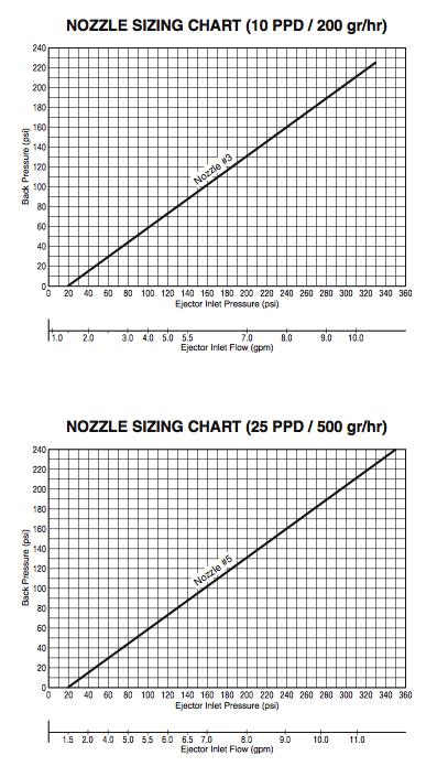
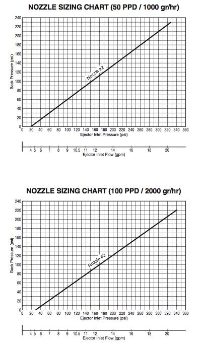
3 TAKE CARE WITH CHLORINE! 1. Always keep chlorine cylinders in an upright position with the valve cap screwed on tight before moving full or empty cylinders. Cylinders should be moved with care. 2. A safety chain must be placed around the cylinder and secured to a wall. Spare full cylinders should also be secured carefully. 3. For best operation and safety, the vacuum regulator and cylinders should be protected from the elements including direct sunlight. 4. Never place heaters or heat lamps directly on a cylinder. 5. Ammonia gas should NOT be stored or fed in the same room with chlorine. Contact of the gases may result in an explosive mixture. IMPORTANT NOTE: Take extreme caution when using chlorine gas manifolds. Manifolds contain pressurized chlorine gas there- by increasing the risk of a pressurized chlorine leak. Enchlor vacuum regulators are designed to mount directly onto the valve of chlorine and sulfur dioxide cylinders. Direct cylinder mounting is the easiest and safest configuration to operate and maintain. With this configuration, the chlorine gas flows under vacuum everywhere beyond the one pressure point at the chlorine cylinder valve. SECTION II: DESIGN AND INSTALLATION NOTES 1. The all vacuum system means that system will shut off at the cylinder valve, should the vacuum line be broken, if water is stopped for any reason, or if the chlorination equipment is physically damaged. 2. Choosing the right feed rate capacity: VACUUM REGULATOR SHOULD BE ON MAXIMUM POSSIBLE FLOW. Imperial Units: GPM x x (PPM) Dosage = PPD Gallons Per Minute Parts Per Million Pounds Per Day (Cl 2) Example: 600 GPM x x 3 PPM = 21.6 PPD In this example a 50 PPD system would be appropriate. Metric Units: LPM x x (PPM) Dosage = GPH Liters Per Minute Parts Per Million Grams Per Hour (Cl 2) 3. TOTAL BACK PRESSURE is the pressure in the pipeline to be chlorinated plus the friction losses in the solution line between the ejector and the point of injection at the pipeline. Ejectors capable of operating with backpressures up to 140 Psig are standard. For higher backpressure consult factory. 4. It is preferable to locate the ejector at the point of solution injection in order to eliminate the need for solution lines. Friction losses in the solution line will increase the ejector backpressure. To reduce the friction losses, increase the solution line internal diameter and limit the number of flow restrictions and turns. Also be sure that the solution line material is resistant to the highly concentrated chlorine mixture. Avoid solution lines wherever possible. 5. The chlorine gas is carried from the vacuum regulator to the ejector through the specified black polyethylene tubing. Up to 100 feet of polyethylene tubing between vacuum regulator and ejector is standard. For longer distances consult factory. 3
4 A typical installation injecting chlorine into a pipe line using city water. (I) INSTALLATION OF EJECTOR (Refer to Figures 1 and 2) 1. Installation of EJECTOR: a. Remove the diffuser from the ejector assembly and place 2 wraps of Teflon tape on diffuser threads. b. Do Not install diffuser into pipe line when assembled with ejector. c. Turn diffuser by hand into NPT threads of pipe line (3/4" or 1 1/4" NPT). Place wrench on diffuser and tighten one half turn maximum. d. Reconnect diffuser to ejector making sure appropriate O-rings are on each side of nozzle and diffuser. 2. Testing of ejector. (Note: The vacuum regulator should still be in the shipping case.) i. Piping hook up to ejector (Refer to Figures 1 and 2 and Servicing Section in this Manual). a. Ejector should be installed down stream at a sufficient distance so that chlorinated water is not recirculated through the booster pump. (See Figure 2.) b. On the water inlet side to the ejector nozzle the following should be installed: a gate valve, Y-strainer, and a pressure gauge. ii. Testing for sufficient pump pressure to operate ejector. Also checking that booster pump (if applicable) operating in the proper direction. Refer to ejector performance charts and tables at end of this manual. Note 1: Ejector must have some back pressure to prevent jetting. (Jetting causes loss of vacuum) Note 2: When chlorinating into a contact chamber a tee should be installed on the solution line with a vacuum breaker to prevent siphoning. a. If operating with city water pressure (no booster pump), open the water inlet valve to the ejector and feel for suction (with your finger) at the fitting on the top of the ejector. b. If pump is operating in proper direction there should be a strong vacuum at the fitting on the top of the ejector. Feel for suction (with your finger) at the fitting on the top of the ejector. c. If the ejector has tested satisfactorily continue on to the next step (Mounting the Vacuum Regulator). SECTION III: SYSTEM INSTALLATION (II) INSTALLATION OF VACUUM REGULATOR NOTE: The chlorine cylinder valve is CLOSED. Do not open until instructed to do so. 1. See that safety chain is secured around chlorine cylinder. 4
5 2. Remove the cylinder protection cap from the chlorine cylinder. 3. Examine the vacuum regulator for obvious damage. 4. Remove masking tape used for shipping purposes. 5. Place lead gasket over vacuum regulator inlet assembly. 6. While placing lead gasket on vacuum regulator see that the filter has not fallen out of inlet assembly. (This filter is necessary to remove particles that will cause venting.) The filter should be inspected each time the cylinder is changed. 7. Mount vacuum regulator on cylinder valve being sure the yoke screw is backed out far enough for sufficient clearance. While tightening the yoke screw be certain that the lead gasket stays in place. Excessive tightening can damage gasket and/or yoke screw. DO NOT USE EXCESSIVE FORCE. See torque specifications below. (III) CONNECTING VACUUM LINES BETWEEN VACUUM REGULATOR AND EJECTOR AND VACUUM REGULATOR VENT TO OUTSIDE (Refer to Figures 1 and 2) 1. The side connector of vacuum regulator is for vacuum line tubing to ejector. (Allow enough vacuum tubing for changing cylinders.) 2. Connect vent tubing to second connector on the vacuum regulator and vent to safe area outside of building. (Place bug screen outside on end of vent tubing.) NOTE: Do Not connect vent lines from two vacuum regulators to one common vent. You must run separate vent lines to the outside, when using multiple vacuum regulators. (IV) REMOTE METERS (Refer to Figure 2) 1. Remote Meters: (Gas flow is from bottom to top through the tube) a. Connect the line in to the bottom tube connector. b. Connect the line out to the ejector to the top connector. A Switchover System injecting chlorine into a pipeline using a turbine positive displacement pump. Pressure relief valve must discharge to a drain or outside of building. Note the by-pass piping from pump discharge through by-pass valve back to suction side of pump. NOTE: By-pass valve must never be completely closed. NOTE: Pump suction and ejector must be from the side of the pipeline, not from the top of the line. SECTION IV: CHLORINATION SYSTEM VACUUM TEST 1. Do Not open chlorine cylinder valve until vacuum test is satisfactorily completed. a. Vacuum Test With the chlorine cylinder still closed, start the ejector booster pump and the meter tube ball should drop to the bottom within about ten seconds. If the ball continues to bounce there is either a leak at the 5
6 lead gasket or a loose connection at the vacuum tube fittings or meter tube. (The tube fittings should be hand tight. It is not necessary to use pliers or a wrench on these fittings. If meter tube needs tightening, use a quarter and finger tighten inlet plug.) At this time the rate valve on the vacuum regulator should be open two or three turns. b. If the ejector is operating properly (pulling sufficient vacuum) then the front bolts should be depressed on both vacuum regulators. c. Turn off water supply to ejector. d. Wait 5 to 10 minutes with water supply off. The ball should remain still at the bottom of the meter tube. e. If the system is vacuum tight proceed to the next step. f. Disconnect vacuum tubing at the vacuum regulator to allow air to enter the system. Reconnect tubing. g. Place one of the vacuum regulators in standby by turning the front knob two turns counter-clockwise and then returning it two turns clockwise. The front bolt should remain protuding per the diagram on the vacuum regulator. SECTION V: START UP OF CHLORINATION Material necessary: A small plastic squeeze bottle, 1/3 full of household ammonia, for detecting chlorine leaks. When ammonia fumes contact chlorine gas a visible smoky vapor is produced. (Wipe up any splashed liquid ammonia.) 1. Open chlorine cylinder valve 1/4 turn and close immediately. 2. Squeeze ammonia bottle at gasket and yoke assembly area: if no vapor appears the seals are tight and it is OK to proceed to the next step. 3. Open chlorine cylinder valve 1/4 turn, leave open, and recheck for chlorine leaks. (1/4 turn open of the cylinder valve is all that s required. The reason we specify 1/4 turn is that the valve can be closed with only 1/4 turn. In an emergency you can shut it off quickly and safely. The wrench stays on the cylinder valve while cylinder is open.) 4. Place one vacuum regulator in standby. This is done by turning the reset knob two turns counterclockwise and then returning it two turns clockwise. The front bolt should remain protruding per the diagram on the vacuum regulator. 5. Turn on water supply or booster pump to ejector and set rate valve to desired flow rate. Read flow rate at center of ball on meter tube scale. 6. Rate valve is not a shut off valve: it is a flow rate control only. To shut off chlorine feed close the chlorine cylinder valve. SECTION VI: SHUT DOWN PROCEDURE 1. Close both chlorine cylinder valves while pump is still running. 2. Wait for ball to rest at bottom of meter tube and the front bolt to be below the surface. 3. Break vacuum by removing the tubing at one of the vacuum regulators and reattach. (Repeat at least 2 times for more complete removal of gas from the system.) 4. Shut down the water supply to the ejector. This procedure of shut down must be followed before a vacuum regulator is removed from a cylinder. NOTE: After installing the vacuum regulator with a new lead gasket on a new cylinder, the vacuum 6
7 tubing should be removed to allow air to enter the system and break the vacuum. Not releasing vacuum and turning on cylinder will slam the diaphragm forward and could cause damage to the diaphragm assembly. You can also accomplish breaking the vacuum by turning the rate valve out of the bonnet. Either way is acceptable. SECTION VII: CHANGING CYLINDERS When one cylinder is empty and the system has switched to feed from the other cylinder then the empty cylinder must be replaced and that vacuum regulator must be placed in standby mode. 1. Tightly close the valve of the empty chlorine cylinder. Follow all applicable guidelines in changing chlorine cylinders. 2. After replacing the empty with a full cylinder, inspect the vacuum regulator, the vacuum regulator filter and (using a new lead gasket) mount the vacuum regulator on the full cylinder. 3. Turn the front knob two turns counter-clockwise and then return two turns clockwise to place the vacuum regulator in standby. The front bolt should remain protruding per the diagram on the vacuum regulator. SECTION VIII: RATE VALVE OPERATION Turn the rate valve counter-clockwise to open it completely. Further turns will completely remove the rate valve from the flow meter tube, which will cause a loss of Cl2 feed. (See Appendix for servicing instructions.) The O-ring seals for the rate valve are locked in place under the valve bonnet and do not come out when the rate valve is pulled out of the bonnet. PREVENTATIVE MAINTENANCE NOTE: Rate valves which are not exercised frequently may experience a build up of a white powdery substance which precipitates out of the chlorine gas. In order to avoid this build up, which can cause the rate valve to become stuck in place, it is recommended that the rate valve be periodically exercised. See Appendix for rate valve maintenance instructions. SECTION IX: TROUBLESHOOTING (I) PRESSURIZED LEAKS 1. Pressurized chlorine leaks are a safety hazard to life and equipment and should be corrected immediately. When searching for this type of leak there are basic safety rules to follow. a. Air breathing pack should be readily available and personnel should know how to use it properly. b. Exhaust fan switch should be located near outside entrance with alternate outside switch c. Chlorine cylinder wrench should remain on the cylinder whenever cylinder is open. d. Plastic squeeze bottle 1/3 full of household ammonia. e. Buddy system used (two people capable of operating system). 2. If a leak is detected the following should be checked first: a. The lead gasket between the chlorine cylinder valve and the vacuum regulator inlet assembly. i. Tighten the half dog screw on the vacuum regulator yoke assembly which is used to secure the inlet assembly to the chlorine cylinder valve. ii. Always use a new lead gasket. b. Chlorine cylinder valve packing. i. Tighten the cylinder valve with care, not excessively! Close the valve if problem persists and notify your chlorine supplier. 7
8 ii. If valve is the problem try to move cylinder with a high degree of safety to an outside location. c. Chlorine leaking out the vent due to the inlet safety shut off valve having dirt on the valve seat. i. Close the chlorine cylinder valves. ii. Wait until the metering ball drops to zero on the flow tube. iii. Turn off water supply to ejector. iv. Now remove the leaking vacuum regulator from the cylinder valve. v. See Appendix for inlet safety shut off valve servicing instructions. vi. After servicing and remounting chlorinator with a new lead gasket, pull a vacuum test before you open the chlorine cylinder valve. See Section IV: Chlorination System Vacuum Test. (II) NO CHLORINE FEED Possible causes: 1. No vacuum being produced by ejector. a. Remove poly tubing from ejector fitting and place your finger on it; you should feel a strong suction. b. If you feel no suction (vacuum) check in this order: i. Nozzle (See Appendix): Turn off water supply and remove nozzle from ejector. (1) It may be clogged or damaged by a stone or other foreign matter. Flush out or run pipe cleaner through carefully. (2) If there is a build-up of rust, iron, or manganese, place the nozzle in a Muriatic acid for five minutes and rinse with water. If you see a black syrup substance you may find it necessary to clean the nozzle on a preventative maintenance schedule. ii. Inlet Water Supply. Check that it is sufficient. Refer to nozzle curves in back of manual. iii. Reduced city water pressure. iv. Y strainer needs cleaning. v. Booster pump cavitating (lost its prime). vi. Booster pump insufficient boost due to wear or single phasing due to loss of one leg of power. vii. Booster pump may have flooded suction. 2. Chlorine flow blocked at vacuum regulator inlet assembly. a. The Inlet filter could be clogged. 3. Out of Chlorine. a. The scale would read 150 lbs. lighter than when cylinder was new. b. Meter tube ball would be at zero. 8
9 APPENDIX A SERVICING THE SYSTEM SECTION A-1: VACUUM REGULATOR (I) CLEANING THE RATE VALVE 1. Unscrew the rate valve knob and stem (by hand) completely out of the rate valve bonnet. NOTE: Be careful not to let the meter tube drop in the next step. It will come loose. 2. Unscrew the rate valve bonnet using pliers (carefully and using a cloth to protect the part). The rate valve sleeve should also be removed. 3. Replace the ORE-VIT-106 O-Ring on the rate valve stem by separating the valve bonnet and sleeve. 4. Lubricate the new O-Rings lightly with Flourolube grease before replacing the sleeve, bonnet and rate valve. (II) CLEANING THE METER TUBE 1. Remember to be careful not to lose the stops or ball in the following steps. 2. Remove the white stops at either end of the tube (you could use a paper clip). 3. Soak the tube in warm water with a cleaner like lime away or Muriatic Acid. Also, brush the inside of the tube with a pipe cleaner. NOTE: Always follow safety precautions with Muriatic Acid and other chemicals. 4. Dry the meter tube and reinstall the ball and stops. 5. It is recommended that new meter tube gaskets be used when reinstalling the meter tube. 6. Reinstall the meter gaskets and meter tube, making sure to center the tube on the top and bottom meter gaskets. 7. Tighten the rate valve bonnet with reasonable force to make a seal. Do not use excessive force. NOTE: All other vacuum regulator repairs should be done by the factory or authorized repair personnel. WARNING: If the vacuum regulator leaks gas out the vent or any other place on the body the problem is most likely caused inside the yoke assembly. It is not recommended that the yoke assembly be disassembled because if it is not done properly dangerous leakage of pressurized gas could result. SECTION A-2: INLET ASSEMBLY WARNING: If the vacuum regulator leaks gas out the vent or any other place on the body the problem is most likely caused inside the yoke assembly. It is recommended that the yoke assembly be disassembled by a person experienced in Chlorine Vacuum Regulator maintenance because if it is not done properly dangerous leakage of pressurized gas could result. 1. Remove the inlet assembly and yoke from the back body. 2. Remove the inlet filter material from the inlet capsule (VRE-141-HYD). 3. Disassemble the inlet assembly using a small flat-head screwdriver to hold the inlet valve (VRE-112- HYD) and a pair of pliers (and a protective cloth) to grip the vent plug (VRE ) to unscrew these two parts. Take care as this assembly is under spring tension and small parts may be difficult to find if dropped. 4. Remove the valve seat (VRE-101-HYD) from the inlet capsule by simply pushing it up through the inlet capsule. Note that the O-ring ORE-VIT-011 is attached to this seat. 6. Clean the inlet capsule, inlet spring (SPE ) and inlet valve using a soft cloth or plastic cleaning pad. Do not use steel wool or other metal cleaning sponges on the inlet valve. 7. Using all new O-rings and new parts as needed, reassemble in reverse order. SECTION A-3: REMOTE METER 9
10 (I) CLEANING THE RATE VALVE 1. Unscrew the rate valve knob and stem (by hand) completely out of the top meter block. 2. In low capacity systems ( 10 PPD or below ) check to see if the point of the valve stem is broken or bent. If it is damaged it must be replaced. 3. Replace O-Rings on the rate valve stem. 4. Lubricate the new O-Rings lightly with Flourolube grease before replacing the rate valve and knob into the top meter block. (II) CLEANING THE METER TUBE 1. While holding the glass meter tube (to prevent it from falling) unscrew the inlet plug at the base of the bottom meter block, until the meter tube can be removed. 2. Remember to be careful not to lose the stops or ball in the following steps. 3. Remove the white stops at either end of the tube (you could use a paper clip). 4. Soak the tube in warm water with a cleaner like lime away or Muriatic Acid. Also, brush the inside of the tube with a pipe cleaner. NOTE: Always follow safety precautions with Muriatic Acid and other chemicals. 5. Dry the meter tube and reinstall the ball and stops. 6. It is recommended that new meter tube gaskets be used when reinstalling the meter tube. 7. Remove the inlet plug completely and inspect the O-Rings. If it has been more than 12 months since they were changed or if there is any noticeable damage, the O-Rings should be replaced. 8. Reinstall the inlet plug, meter gaskets and meter tube, making sure to center the tube on the top and bottom meter gaskets. 9. Tighten the inlet plug with reasonable force to make a seal. Do not use excessive force. SECTION A-4: EJECTOR/CHECK VALVE ASSEMBLY (I) LOSS OF VACUUM AT THE EJECTOR: If vacuum is lost at the ejector and water supply is sufficient, then the nozzle is most likely clogged, broken or loose. Before working on the ejector it must first be isolated so that water will not leak when the ejector is removed. 1. First detach the intake side (nozzle) of the ejector from the pipeline. 2. For 3/4" line size ejectors rotate the complete ejector body counter clockwise. This loosens the threaded portion of the nozzle from the diffuser. It also eliminates the need for pliers on the nozzle which could damage the plastic. For 1-1/4" line size ejectors remove the two flanges to remove the ejector. 3. Inspect the nozzle for: Pipe scale, stones, dirt, etc... Build-up of iron, manganese, calcium, etc The nozzle should be soaked and brushed with warm water mixed with a cleaner like Muriatic Acid. NOTE: TAKE CARE NOT TO SCRATCH OR ATTEMPT TO MODIFY THE ORIFICE IN ANY WAY. 5. Using two new ORE-VIT-214 O-rings the ejector can now be reassembled. When reassembling 3/4" line size ejectors the nozzle and diffuser should be screwed together hand tight leaving the ejector body 90 degrees to the left of its final position. Once the nozzle and diffuser are hand tight, the ejector can then be turned the final 90 degrees. WARNING: Do not use excessive force in tightening the nozzle, diffuser and ejector assembly. The ejector is constructed of PVC and excessive force can break the parts. (II) SERVICING THE EJECTOR CHECK VALVE ASSEMBLY: If water leaks back into the system, this means that the ejector check valve has failed. This could be caused by incorrect assembly, a failed gasket, O-Ring or diaphragm, or foreign material lodged in the check valve. 1. Remove the four bolts holding the ejector body together. 2. Inside you will find a diaphragm assembly and a spring. 10
11 3. The diaphragm assembly can usually be unscrewed by hand. If it is too tight, carefully try large jaw pliers or a vice. Note that a plastic support diaphragm is on the top side of the rubber diaphragm. The purpose is to protect the softer rubber diaphragm in installations with high pressure. 4. Inspect the rubber diaphragm for holes or weak points. 5. Inspect the ORE-VIT-203 O-Ring. Replace if damaged. 6. Reassemble the diaphragm assembly, preferably with a new rubber diaphragm, DIE-112-HYD. 7. Install the assembly in the recess between the ejector body halves being careful to install the spring properly below the assembly. SECTION A-5: SWITCHOVER MODULE (I) OPERATION OF THE MODULE GENERAL: This device requires no outside setting or adjustment. The switchover module allows gas to flow from one of the two intake ports at a time, keeping the other sealed. It will continue to feed from first side until the vacuum level rises sufficiently (in the event of an empty cylinder or closing of the cylinder valve), at which time an internal spring loaded mechanism automatically switches to open the second intake port and to close the first intake port. NOTE: In low capacity systems where the feed rate is less than 10 PPD or the time between switching is more than two weeks, it is recommended that the module be exercised weekly. If the module is left in one position for long periods of time, it may have a tendency to stick in one position. To exercise the module it can be disconnected from both vacuum regulators with the ejector still connected and operating. Use a finger or thumb to close the open intake port of the module until it switches to feed from the other port. Repeat this process 5 to 10 times. (II) SERVICING THE MODULE GENERAL: If the module does not operate correctly first try exercising it as described in the last paragraph. If this does not work the unit must be disassembled. 1. Remove the four screws that secure the top cap onto the main body. 2. Remove the four screws that secure each of the side caps onto the main body. 3. Remove the diaphragm assemblies and the toggle mechanism noting their orientations for reassembly. 4. Inspect the guide pin to ensure that it is free of dirt or burrs. If not clean and polish it with alcohol until it is able to slide freely. 5. Inspect the O-Ring seats on the diaphragm assemblies. Ensure that they are free of any residue and should be cleaned with alcohol being careful not to scratch them. 6. Replace the O-Rings unless they are less than 12 months old or are in perfect condition. 7. Inspect the diaphragms to ensure that they are free of tears or holes. If they are not in good condition, they should be replaced. 8. Reassemble the module in reverse order. 11

12 1 inlet plug MIE-101-HYD 2 bottom meter block MBE-103-HYD 3 oring ORE-VIT meter gaskets GAE-VIT-101/2/3 5 meter tube MTE-108-xxx-S 6 oring ORE-VIT pin guide not used 8 guide pin VRE-333-HYD 9 oring ORE-VIT face plate VRE-105-HYD 11 screw BTE-STA top meter block MBE-100-HYD 13 rate valve seat RVE-104-HYD 14 oring ORE-VIT oring ORE-VIT valve bonnet RVE-100-HYD 17 rate valve RVE-103-HYD 18 oring ORE-VIT front body VRE-10A-HYD 20 diaphragm DIE oring ORE-VIT back body VRE-10B-HYD 23 oring ORE-VIT screw BTE-STA oring ORE-VIT yoke assembly VRE-346-HYD 27 inlet adaptor VRE-141-HYD 28 filter holder VRE-300-HYD 29 lead agsket GAE-LED inlet filter screen VRE filter VRE teflon filter VRE-210-HYD 33 inlet valve VRE-112-HYD 34 inlet valve seat VRE-101-HYD 35 oring ORE-VIT inlet spring SPE inlet washer VRE spring reatiner VRE vent plug VRE oring ORE-VIT diaphragm bolt VRE-363-HYD 42 oring - series 5000 ORE-VIT-028 oring - series 500 ORE-VIT diaphragm bolt VRE-363-HYD 44 flow tube VRE oring ORE-VIT diaphragm front plate VRE vent spring SPE rate valve knob included with #17 49 set screw included with #17 50 tubing connector TCE shield optional not shown meter block bolts BTE-STA-126 not shown yoke bolts BTE-STA-181 SERIES 5000 VACUUM REGULATOR 12

13 1 top body EJE-550-HYD 2 oring ORE-VIT check assm bolt EJE-553-HYD 4 check assm nut EJE-552-HYD 5 rolling diaphragm DIE-112-HYD 6 spring SPE bottom body EJE-551-HYD 8 nozzle CNE-xxx-HYD 9 diffuser EJE-163-HYD 10 tubing connector TCE oring ORE-VIT oring ORE-VIT nut NTE-STA bolt BTE-STA-B57 15 brackets* EJE-136-HYD 16 bolt* BTE-STA nut* NTE-STA body armor* c/f 19 support diaphragm DIE-105-HYD * used on high pressure version only c/f consult factory SERIES 5000 EJECTOR 13
14 14

15 1 valve bonnet RVE-100-HYD 2 rate valve RVE-103-HYD 3 top meter block MBE-100-HYD 4 rate valve seat RVE-104-HYD 5 meter tube MTE-108-xxx-S 6 bottom meter block MBE-103-HYD 7 inlet plug MIE-101-HYD 8 back body MPE-250-HYD 9 oring ORE-VIT oring ORE-VIT oring ORE-VIT oring ORE-VIT meter gasket GAE-VIT-101/2/3 14 bolt BTE-STA rate valve knob included with #2 16 set screw included with #2 17 tubing connector TCE xxx- specify capacity when ordering SERIES 5000 REMOTE METER PANEL 15
16 16
17 17
Model VR6 System. Installation, Operation & Maintenance
 Model VR6 System Installation, Operation & Maintenance General: All Archer Instruments chlorination systems are carefully designed and tested for years of safe, accurate field service. All Archer Instruments
HGC-200 Hydro Gas Chlorinator
 HGC-200 Hydro Gas Chlorinator ProMinent Fluid Controls Pty Ltd Head Office: Unit 4, 4 Narabang Way BELROSE NSW 2085 AUSTRALIA (PO Box 85, BELROSE WEST NSW 2085) Phone: (02) 9450 0995 Fax: (02) 9450 0996
Chemical Injection Technologies Installation/Service Bulletin
 Bulletin 4002 Chemical Injection Technologies Installation/Service Bulletin SUPERIOR Series CL-16/26/56 Automatic Switchover Gas Chlorinator - Installation & Operation IMPORTANT!! READ THESE PRECAUTIONS
Automatic Switchover Gas Chlorination Systems Series 900
 Automatic Switchover Gas Chlorination Systems Series 900 Instruction Manual All Hydro Instruments Chlorination systems are carefully designed and tested for years of safe, accurate field service. All Hydro
Instruction Manual - Diaframless TM Ejector Chlorine, Sulfur Dioxide and Ammonia
 Instruction Manual - Diaframless TM Ejector Chlorine, Sulfur Dioxide and Ammonia - 1-122.6010.6 These instructions describe the installation, operation and maintenance of the subject equipment. Failure
Instruction Manual O-Ring Ejector Chlorine & Sulfur Dioxide to 500 PPD (10 kg/h)
") Instruction Manual O-Ring Ejector Chlorine & Sulfur Dioxide to 500 PPD (10 kg/h) 100 PPD (2 kg/h) Maximum 250 PPD (5 kg/h) Maximum 500 PPD (10 kg/h) Maximum - 1-122.6006.9 These instructions describe the
Instruction Manual O-Ring Ejector Chlorine & Sulfur Dioxide to 500 PPD (10 kg/h) 100 PPD (2 kg/h) Maximum 250 PPD (5 kg/h) Maximum 500 PPD (10 kg/h) Maximum - 1-122.6006.9 These instructions describe the
Vacuum Operated Liquid Chemical Feed Systems
 Vacuum Operated Liquid Chemical Feed Systems Instruction Manual All HYDRO Chemical Feed systems are carefully designed and tested for years of safe, accurate field service. All HYDRO systems are tested
Instruction Manual ADVANCE Series 480 Vacuum Regulator
 Instruction Manual ADVANCE Series 480 Vacuum Regulator 80 60 40 20 R - 1-100.6001.15 These instructions describe the installation, operation and maintenance of the subject equipment. Failure to strictly
Assembly Drawing: W-311B-A01, or as applicable Parts List: W-311B-A01-1, or as applicable Special Tools: , , &
 REDQ Regulators Model 411B Barstock Design Powreactor Dome Regulator OPERATION AND MAINTENANCE Contents Scope..............................1 Installation..........................1 General Description....................1
Instruction Manual Series 200 ADVANCE Cylinder or Ton Container Mounted Vacuum Regulators
 Instruction Manual Series 200 ADVANCE Cylinder or Ton Container Mounted Vacuum Regulators 100 & 250 PPD (2 & 5 kg/h) Cylinder Mounted 500 PPD (10 kg/h) Cylinder Mounted 500 PPD (10 kg/h) Ton Container
2008 by Controlmatik ABW
 I N S T R U C T I O N M A N U A L F OR Installation and use of high capacity Vacuum regulator 2008 by Controlmatik ABW CONTENTS 1 GENERAL... 2 2 THE CHLORINE GAS DOSING SYSTEM... 2 2.1 Parts of the chlorine
Installation, Operation and Maintenance Manual for Back Pressure Regulator
 Installation, Operation and Maintenance Manual for Back Pressure Regulator Model 8860 2009 Groth Corporation IOM-8860 Rev. B 12541 Ref. ID: 95565 Page 2 of 13 Table of Contents I. INTRODUCTION 3 II. DESIGN
LRS(H)4 USER MANUAL. Read the complete manual before installing and using the regulator.
4 USER MANUAL. Read the complete manual before installing and using the regulator.") LRS(H)4 USER MANUAL Read the complete manual before installing and using the regulator. WARNING INCORRECT OR IMPROPER USE OF THIS PRODUCT CAN CAUSE SERIOUS PERSONAL INJURY AND PROPERTY DAMAGE. Due to the
LRS(H)4 USER MANUAL Read the complete manual before installing and using the regulator. WARNING INCORRECT OR IMPROPER USE OF THIS PRODUCT CAN CAUSE SERIOUS PERSONAL INJURY AND PROPERTY DAMAGE. Due to the
RS(H)10,15 USER MANUAL. Read the complete manual before installing and using the regulator.
10,15 USER MANUAL. Read the complete manual before installing and using the regulator.") RS(H)10,15 USER MANUAL Read the complete manual before installing and using the regulator. WARNING INCORRECT OR IMPROPER USE OF THIS PRODUCT CAN CAUSE SERIOUS PERSONAL INJURY AND PROPERTY DAMAGE. Due to
RS(H)10,15 USER MANUAL Read the complete manual before installing and using the regulator. WARNING INCORRECT OR IMPROPER USE OF THIS PRODUCT CAN CAUSE SERIOUS PERSONAL INJURY AND PROPERTY DAMAGE. Due to
EASTERN ENERGY SERVICES PTE LTD. 60 Kaki Bukit Place #02-19 Eunos Tech Park Singapore, SG Singapore Telephone: Fax:
 2 Table Of Contents 1. Introduction 3 2. About this Manual 3 3. Contacting YZ Systems 3 4. Vessel Components 4 5. Specifications 5 6. Application 6 7. Theory of Operation 7 8. DuraSite Installation & Use
CAPITAL CONTROLS SERIES NXT3000
 CAPITAL CONTROLS SERIES NXT3000 Modular design gas feed system with self contained automatic switchover capability. The Series NXT3000 Gas Feed System is a family of vacuumoperated, solution-feed gas dispensing
Anderson Greenwood Series 93 Positive Pressure POSRV Installation and Maintenance Instructions
 Before installation these instructions must be fully read and understood Installation and maintenance instructions for Series 93 Positive Pressure Pilot Operated Safety Relief Valves (POSRV). The intent
Operating Instructions Model and Hydrostatic Test Pump
 Operating Instructions Model 39300 and 39301 Hydrostatic Test Pump Dimension Weight Pump Style Capacity Pressure Motor Lubrication Control Gauge Inlet Connection Outlet Connection Discharge Hose Hose Ends
Capital Controls Series NXT3000 Modular design gas feed system with self-contained automatic switchover capability.
 Capital Controls Series NXT3000 Modular design gas feed system with self-contained automatic switchover capability. The Series NXT3000 Gas Feed System is a family of vacuum-operated, solution-feed gas
Pressure Dump Valve Service Kit for Series 2300 Units
 Instruction Sheet Pressure Dump Valve Service Kit for Series 00 Units. Overview The Nordson pressure dump valve is used to relieve hydraulic pressure instantly in Series 00 applicator tanks when the unit
RHPS Series RD(H)F40 User Manual. Read the complete manual before installing and using the regulator.
F40 User Manual. Read the complete manual before installing and using the regulator.") RHPS Series RD(H)F40 User Manual Read the complete manual before installing and using the regulator. 2 WARNING Before removing a regulator from the system for service, you must depressurize system purge
RHPS Series RD(H)F40 User Manual Read the complete manual before installing and using the regulator. 2 WARNING Before removing a regulator from the system for service, you must depressurize system purge
AIR-OPERATED DOUBLE DIAPHRAGM PUMP USER S MANUAL
 00, 0, 000 00, 000, 00 A. TECHNICAL INFORMATION Model 00 Inlet/Outlet " Air Inlet /" 0 / 000 /" /" 00 /" /" 000 /" /" 00 /" /" Flow Rate GPM/ 0LPM GPM/ 0LPM GPM/ LPM GPM/ LPM GPM/ 0LPM GPM/ 0LPM Maximum
Welker Sampler. Model GSS-1. Installation, Operation, and Maintenance Manual
 Installation, Operation, and Maintenance Manual Welker Sampler Model GSS-1 The information in this manual has been carefully checked for accuracy and is intended to be used as a guide to operations. Correct
PRS(TC)4,8 USER MANUAL. Read the complete manual before installing and using the regulator.
4,8 USER MANUAL. Read the complete manual before installing and using the regulator.") PRS(TC)4,8 USER MANUAL Read the complete manual before installing and using the regulator. WARNING INCORRECT OR IMPROPER USE OF THIS PRODUCT CAN CAUSE SERIOUS PERSONAL INJURY AND PROPERTY DAMAGE. Due to
PRS(TC)4,8 USER MANUAL Read the complete manual before installing and using the regulator. WARNING INCORRECT OR IMPROPER USE OF THIS PRODUCT CAN CAUSE SERIOUS PERSONAL INJURY AND PROPERTY DAMAGE. Due to
Model Secure-Gard Pilot Operated Vent Valve SECTION II. Remove all packing material inside and outside of the valve prior to installation.
 INSTALLATION, OPERATION AND MAINTENANCE MANUAL (IOM) IOM - 1049 01-17 Model 1049 Secure-Gard Pilot Operated Vent Valve ISO Registered Company SECTION I I. DESCRIPTION AND SCOPE The Model 1049 Secure-Gard
RG1200 Service and Repair Manual
 Dive Rite RG 1200 Regulator Service and Repair Manual Page 1 Text and Photography by Pete Nawrocky Copyright ( ) 1999-2000, Lamartek, Inc., dba Dive Rite RG1200 Service and Repair Manual First Stage.........................................
Model: 43T. Bermad Pressure Relief Valve
 Model: 43T Bermad Pressure Relief Valve Installation Operation Maintenance Manual () Rev.C1_01.08.17 Page 1 of 10 Safety First BERMAD believes that the safety of personnel working with and around our equipment
3/8" Dr. Air Butterfly Impact Wrench
 8192106 3/8" Dr. Air Butterfly Impact Wrench Owner s Manual Read and understand all instructions before use. Retain this manual for future reference. Specifications Construction: Polished aluminum and
Installation of Your SprayMaster System
 Installation of Your SprayMaster System 1. At the installation site, remove all equipment from the corrugated box and the polyethylene drum and replace the drum lid. Check the picture to identify each
Installation, Operation, and Maintenance Manual
 Installation, Operation, and Maintenance Manual Welker Probe Instrument Regulator Model The information in this manual has been carefully checked for accuracy and is intended to be used as a guide for
Type S301 & S302 Gas Regulators INTRODUCTION INSTALLATION. Scope of Manual. Description. Specifications. Type S301 and S302. Instruction Manual
 Fisher Controls Instruction Manual Type S301 & S302 Gas Regulators October 1981 Form 5180 WARNING Fisher regulators must be installed, operated, and maintained in accordance with federal, state, and local
Contents. Stainless Steel Side Block. 1.1 Separating the Side Block. Stainless Steel Side Block Reassembly of. Assembly from the Helmet Shell
 Separating the Side Block Assembly from the Helmet Shell Contents SSB-1 SSB-3 SSB-5 SSB-5 SSB-7 1.1 Separating the Side Block Assembly from the Helmet Shell 1.2 Side Block Assembly Replacement 1.3 Defogger
Installation, Operation, and Maintenance Manual
 Installation, Operation, and Maintenance Manual Welker The information in this manual has been carefully checked for accuracy and is intended to be used as a guide for the installation, operation, and
Pressure Dump Valve Service Kit for Series 3000 Units
 Instruction Sheet Pressure Dump Valve Service Kit for Series 000 Units. Overview The Nordson pressure dump valve is used to relieve hydraulic pressure instantly in Series 00, 400, 500, and 700 applicator
PENBERTHY SUBMERSIBLE AUTOMATIC SUMP DRAINER INSTALLATION, OPERATION AND MAINTENANCE INSTRUCTIONS
 Before installation, these instructions must be read carefully and understood. PRODUCT WARRANTY Emerson warrants its Penberthy products as designed and manufactured to be free of defects in the material
ACV-10 Automatic Control Valve
 ACV-10 Automatic Control Valve Installation, Operation & Maintenance General: The Archer Instruments ACV-10 is a precision automatic feed rate control valve for use in vacuum systems feeding Chlorine,
TECHNICAL DATA. Pressure Regulation 531a. April 24, 2009
 April 24, 29 Pressure Regulation 531a 1. DESCRIPTION The Viking Regulating Valve is a direct-acting, single-seated, spring-loaded diaphragm valve. When installed as a pilot regulating valve on a Viking
Installation, Operation, and Maintenance Manual
 Installation, Operation, and Maintenance Manual Welker Instrument Supply Pressure System Model WIC The information in this manual has been carefully checked for accuracy and is intended to be used as a
LRS(H)4 Pressure-Reducing Regulator User Manual
4 Pressure-Reducing Regulator User Manual") LRS(H)4 Pressure-Reducing Regulator User Manual Read the complete manual before installing and using the regulator. 2 Safe Product Selection When selecting a product, the total system design must be considered
LRS(H)4 Pressure-Reducing Regulator User Manual Read the complete manual before installing and using the regulator. 2 Safe Product Selection When selecting a product, the total system design must be considered
Model PSI Compressor with 3-Gallon Air Tank 12VDC
 Model 6350 150 PSI Compressor with 3-Gallon Air Tank 12VDC IMPORTANT: It is essential that you and any other operator of this product read and understandd the contents of this manual before installing
Installation Instructions
 Installation Instructions S65-135 (Circular) S65-136 (Semi-Circular) Air Valve Retrofit For Non-Sectional Classic Washfountain Table of Contents.......................2-6 Metering Air Valve Parts List....................6
SALCO PRODUCTS, INC. PRESSURE RELIEF VALVE STORAGE, INSTALLATION, OPERATING, MAINTENANCE/TESTING, AND INSPECTION INSTRUCTIONS
 STORAGE INSTRUCTIONS Until it is time to install a new or reconditioned valve on the car, the valve must be kept in its original packaging in order to protect it from dirt and damage. INSTALLATION INSTRUCTIONS
VALVES & MEASUREMENT
 VALVES & MEASUREMENT TBV OPERATION AND MAINTENANCE MANUAL SERIES 1100: THREE PIECE BALL VALVE For technical questions, please contact the following: Engineering Department 1537 Grafton Road Millbury, MA
TECHNICAL DATA. Page 1 of 12
 Page 1 of 12 1. DESCRIPTION The Viking Regulating Valve is a direct-acting, single-seated, spring-loaded diaphragm valve. When installed as a pilot regulating valve on a Viking Model H or J Flow Control
TBV OPERATION AND MAINTENANCE MANUAL SERIES 2800: FLANGED BALL VALVE. For technical questions, please contact the following:
 TBV OPERATION AND MAINTENANCE MANUAL SERIES 2800: FLANGED BALL VALVE For technical questions, please contact the following: Engineering Department 1537 Grafton Road Millbury, MA 01527 Phone: (508) 887-9400
Needle valve. Contents. User s Manual. (1) Be sure to read the following warranty clauses of our product 1. (2) General operating instructions 2
 Be sure to read the following warranty clauses of our product 1. (2) General operating instructions 2") Serial No. H-V024-E-7 Needle valve User s Manual Contents (1) Be sure to read the following warranty clauses of our product 1 (2) General operating instructions 2 (3) General instructions for transportation,
Serial No. H-V024-E-7 Needle valve User s Manual Contents (1) Be sure to read the following warranty clauses of our product 1 (2) General operating instructions 2 (3) General instructions for transportation,
RD(H)20/25 Pressure-Reducing Regulator User Manual
20/25 Pressure-Reducing Regulator User Manual") RD(H)20/25 Pressure-Reducing Regulator User Manual Read the complete manual before installing and using the regulator. 2 Safe Product Selection When selecting a product, the total system design must be
RD(H)20/25 Pressure-Reducing Regulator User Manual Read the complete manual before installing and using the regulator. 2 Safe Product Selection When selecting a product, the total system design must be
WW-730. Pressure Sustaining/Relief Control Valve
 WW-730 Pressure Sustaining/Relief Control Valve Installation Operation & Maintenance Page 1 of 6 1. DESCRIPTION The Model 730 Pressure Relief / Sustaining Valve is an automatic control valve designed to
SUMMITTM 400 & 600. Natural Gas Barbecues. Step-By-Step Guide
 SUMMITTM 400 & 600 Natural Gas Barbecues Step-By-Step Guide W E B E R W E B E R W E B E R W E B E R Summit 400 NG Summit 600 NG CANADIAN GAS ASSOCIATION R A P P R O V E D WARNING: Follow all leak check
Operation Manual Piston Sensed Gas Pressure Regulators
 687 Technology Way Napa, CA 94558 Phone: (707) 259-0102 FAX: (707) 259-0117 www.aptech-online.com Operation Manual Piston Sensed Gas Pressure Regulators (Models KT9, KT10, Welded KT10, KT12) Table of Contents:
Anti-flood device Model B-1
 December 4, 2009 Dry Systems 123a 1. DESCRIPTION The Anti-flood Device is required when Viking accelerators are installed on dry systems according to Viking Model E-1 Accelerator Trim Charts. In the SET
Halsey Taylor Owners Manual STOP!
 Halsey Taylor Owners Manual 4710 Freeze Resistant Floor Mounted Steel Fountain STOP! PLEASE READ THE FOLLOWING INFORMATION. ITALLATION ITRUCTIO FOR THE 4710FR FTN. WITH 97243C SINGLE VALVE CONTROL ASSEMBLY
MAINTENANCE PROCEDURE FOR X 650
 MAINTENANCE PROCEDURE FOR X 650 X 650 25. juli 2005-1/6 MAINTENANCE PROCEDURE FOR X 650 2 ND STAGE WARNING: This maintenance procedure is only for appointed Scubapro technicians that completed a course
Halsey Taylor Owners Manual 4410 Freeze Resistant Tubular Fountain STOP!
 Halsey Taylor Owners Manual 4410 Freeze Resistant Tubular Fountain STOP! PLEASE READ THE FOLLOWING INFORMATION. ITALLATION ITRUCTIO FOR THE 4410FR FTN. WITH 97243C SINGLE VALVE CONTROL ASSEMBLY ARE LOCATED
Pneumatic Powered - Plunger Pumps
 Models 42/62/82 D Series P.O. Box 80769 Lafayette, LA 70598-0769 (337) 235-9838 FAX (337) 235-9852 www.sidewinderpumps.com Pneumatic Powered - Plunger Pumps Suggested Installation & Operating Instructions
1 DRIVE INDUSTRIAL IMPACT WRENCH
 1 DRIVE INDUSTRIAL IMPACT WRENCH 92622 ASSEMBLY AND OPERATING INSTRUCTIONS 3491 Mission Oaks Blvd., Camarillo, CA 93011 Visit our Web site at http://www.harborfreight.com Copyright 2004 by Harbor Freight
THE HF-300 SERIES. Operating and Service Manual. Series includes all variants of HF-300/301
 THE HF-300 SERIES Operating and Service Manual Series includes all variants of HF-300/301 Issue A July 2015 1 TABLE OF CONTENTS 1. Description... 3 2. Installation... 3 3. Operation... 4 3.1. Spring Loaded...
PART 1 GENERAL..2 Components of the gas chlorination system include, but are not limited to the following:
 PART 1 GENERAL 1.1 DESCRIPTION.1 This section includes the supply, delivery and installation, testing and placement into operation of a gas chlorination system, and appurtenances as specified herein and
INSTALLATION. and INSTRUCTION MANUAL. for QUALITY AIR BREATHING SYSTEMS. Model 50 Systems Outfitted with ABM-725 Monitor C O M P A N Y
 INSTALLATION and INSTRUCTION MANUAL for QUALITY AIR BREATHING SYSTEMS Model 50 Systems Outfitted with ABM-725 Monitor M A R T E C H S E R V I C E S C O M P A N Y OFFICE: (507) 843-4700 P.O. BOX 7079 Toll
Service and Repair Manual
 II stage R2 Ice/ Special, II stage R 1 Pro DOWNSTREAM 2 nd STAGE REGULATOR Service and Repair Manual Introduction Safety Precautions...4 General Procedures, Maintenance Schedules...5 Initial Inspection
Installation Troubleshooting Maintenance Instructions Installation / Start-up
 Model ZW207 Installation Troubleshooting Maintenance Instructions Installation / Start-up NOTE: Flushing of all pipe lines is to be performed to remove all debris prior to installing valve. 1. For making
4400 TwinHybrid Gas Seal
 4400 TwinHybrid Gas Seal EQUIPMENT PREPARATION MECHANICAL SEAL INSTALLATION INSTRUCTIONS 1 2 200.005" 0,13 mm 125 µ" 3,2 µm R a 3 4 32 µ" 0,8 µm R a 1000 ±.002" 0,05mm CAUTIONS These instructions are general
TECHNICAL DATA ANTI-FLOOD DEVICE MODEL B-1 1. DESCRIPTION
 Page 1 of 6 1. DESCRIPTION The Model B-1 Anti-flood Device is required when Viking accelerators are installed on dry systems according to Viking Model E-1 Accelerator Trim Charts. In the SET condition,
Float Operated Level Controllers
 CONTENTS Float Operated Level Controllers IM0015 Nov. 2014 PAGE Introduction 1 Scope 1 Description 1 Specification 1 Control Installation 2 INTRODUCTION Side Mount Back Mount Prior to installing, the instructions
V43 Pressure Actuated Water Regulating Valve
 FANs 125, 121 Product/Technical Bulletin V43 Issue Date 0996 V43 Pressure Actuated Water Regulating Valve The V43 Pressure Actuated Water Regulating Valves are designed to regulate water flow for water-cooled
ATD LB PRESSURE BLASTER INSTRUCTION MANUAL
 ATD-8402 90LB PRESSURE BLASTER INSTRUCTION MANUAL SAVE THESE INSTRUCTIONS SAFETY INSTRUCTIONS FOR SANDBLASTER 1. Before opening the tank release the air pressure on the sand tank. To do this, turn off
WW-720. Pressure Reducing Control Valve
 WW-720 Pressure Reducing Control Valve (Size Ranges: 2-4 and 6-14 ) Installation Operation & Maintenance Page 1 of 6 1. DESCRIPTION The Model 720 Pressure Reducing is an automatic control valve (powered
INTRODUCTION IMPORTANT NOTES AND WARNINGS
 INSTRUCTION BULLETIN 26 044 SE Dixie Cutoff Road, Stuart, Florida 34994 USA Phone: (772) 288-4854 Fax: (772) 287-3238 www.regalchlorinators.com Email: regal@regalchlorinators.com REGAL Gas Chlorinator,
Chlorinator. MODEL C-731 (Floor Mounted)
") Chlorinator MODEL C-731 (Floor Mounted) CHLOROTECH Model C-731 is the advance technology Chlorinator designed to feed chlorine gas at a controlled rate. The flow rate of gas is maintained by constant positive
Chlorinator MODEL C-731 (Floor Mounted) CHLOROTECH Model C-731 is the advance technology Chlorinator designed to feed chlorine gas at a controlled rate. The flow rate of gas is maintained by constant positive
1200B2 Series Service Regulators. Instruction Manual
 00B Series Service Regulators Instruction Manual 00B Series Service Regulators 0 Elster American Meter 00B Series Service Regulators General Information The 00B Series Service Regulators are available
Summary of Accumulators These operating instructions apply to the accumulators listed in the table shown below.
 Page 1 of 15 Summary of Accumulators These operating instructions apply to the accumulators listed in the table shown below. Model Number A25-XXXX-3.6K Series A40-XXXX-3K Series A40X-XXXX-3.6K Series A60-XXXX-3K
Suggested Installation & Operating Instructions for Sidewinder Pumps
 Model 164 C P.O. Box 80769 Lafayette, LA 70598-0769 (337) 235-9838 FAX (337) 235-9852 www.sidewinderpumps.com Pneumatic Powered - Plunger Pump Suggested Installation & Operating Instructions for Sidewinder
THE BP-301 SERIES. Operating and Service Manual. Series includes all variants of BP-301 (LF 0.1Cv / MF 0.5Cv)
") THE BP-301 SERIES Operating and Service Manual Series includes all variants of BP-301 (LF 0.1Cv / MF 0.5Cv) Issue B October 2015 1 TABLE OF CONTENTS 1. Description... 3 2. Installation... 3 3. Operation...
THE BP-301 SERIES Operating and Service Manual Series includes all variants of BP-301 (LF 0.1Cv / MF 0.5Cv) Issue B October 2015 1 TABLE OF CONTENTS 1. Description... 3 2. Installation... 3 3. Operation...
Model GP PRESSURE REDUCING VALVE Installation & Operation Manual
 Model GP-2000 PRESSURE REDUCING VALVE Installation & Operation Manual Please read this bulletin thoroughly before using the pressure reducing valve, so that you may do so correctly and safely. Please carefully
Constant Pressure Crude Oil Container Model CPCCP
 Installation, Operations, and Maintenance Manual Constant Pressure Crude Oil Container Model CPCCP The information in this manual has been carefully checked for accuracy and is intended to be used as a
User's Manual. MixRite TF 10. Edition 05.08
 User's Manual MixRite TF 10 Edition 05.08 1 Tefen MixRite TF 10 fertilizer and chemicals Injector Congratulations on your purchase of one of Tefen s high quality products. To get the best results from
OPERATING AND MAINTENANCE MANUAL
 Series 4300 Engineered Performance TABLE OF CONTENTS 0 INTRODUCTION 1 1 Scope 1 2 Description 1 3 Specifications 1 0 INSTALLATION 1 1 Mounting 1 2 Piping 1 1 Connecting Process Pressure 2 2 Vent Connections
FLANGED TWO-PIECE BALL VALVES
 INTRODUCTION This instruction manual includes installation, operation, and maintenance information for FNW flanged split-body ball valves. This manual addresses lever operated ball valves only. Please
RS(H)20, 25 USER MANUAL
20, 25 USER MANUAL") RS(H)20, 25 USER MANUAL Read the complete manual before installing and using the regulator. WARNING Before removing a regulator from the system for service, you must depressurize system purge the system
RS(H)20, 25 USER MANUAL Read the complete manual before installing and using the regulator. WARNING Before removing a regulator from the system for service, you must depressurize system purge the system
Blue River Technologies Port-A-Poly Mixer w/2.5 GPH LMI Pump And Secondary Water Dilution Line INSTALLATION AND OPERATION
 Blue River Technologies Port-A-Poly Mixer w/2.5 GPH LMI Pump And Secondary Water Dilution Line INSTALLATION AND OPERATION Install your Blue River Technologies Port-A-Poly mixing system in a clean dry area.
INSTALLATION, OPERATION, AND MAINTENANCE MANUAL WELKER RELIEF VALVE
 INSTALLATION, OPERATION, AND MAINTENANCE MANUAL WELKER RELIEF VALVE MODELS RV-1 RV-2 RV-2CP RV-3 DRAWING NUMBERS AD017A[ ] AD018A[ ] AD020A[ ] AD282BO MANUAL NUMBER IOM-033 REVISION Rev. E, 3/28/2016 TABLE
Aquor House Hydrant V2
 Aquor House Hydrant V2 IN-WALL OUTDOOR FAUCET SYSTEM FLUSH-MOUNT QUICK-CONNECT SELF-DRAINING ANTI-SIPHON NON-FREEZE VBH-SERIES AQUOR HOUSE HYDRANT V2: WALL HYDRANT / FREEZELESS SILLCOCK Freezeless sillcock
Rejuvenation Instructions
 Rejuvenation Instructions #401 Air Systems UPR This NRI covers the following: Understanding the applications and operation of flow meters. Understand the application and operation of test pressure gauges.
PRO SINK -R 1 and 2. Dilution system CONTENTS
 PRO SINK -R 1 and 2 Dilution system CONTENTS 1.0 Product description 2 2.0 Warnings.. 3 3.0 Installation procedure 4 4.0 Plumbing connections 4 5.0 Technical features.. 5 6.0 Maintenance... 6 7.0 Troubleshooting......6
TECHNICAL DATA CAUTION
 Page 1 of 6 1. DESCRIPTION The Viking Model D-2 Accelerator is a quick-opening device, with an integral anti-flood assembly, used to increase the operating speed of a differential type dry pipe valve.
MEGR-1627 Instruction Manual
 MEGR-1627 HIGH FLOW GAS REGULATOR Instruction Manual- Look Inside For: Description Installation Remote Vent Line Installations Startup and Adjustment Shutdown Maintenance Body Maintenance Procedures Diaphragm
Bermad Model:
 Bermad Model: 405-02 Manually Operated Hydraulic Valve INSTALLATION OPERATION MAINTENANCE Application Engineering BERMAD 1. Safety First BERMAD believes that the safety of personnel working with and around
RB70 Automatic Diluent Valve Maintenance Manual. Version 1.1 November 2006 Written by Tino de Rijk. Page 1 of 23
 RB70 Automatic Diluent Valve Maintenance Manual Version 1.1 November 2006 Written by Tino de Rijk Page 1 of 23 Table of Contents 1. Introduction... 3 2. ADV diagram and parts list (Pre June 2006)... 4
COMBINATION AIR RELEASE DEGASSING (CARD) VALVES INSTALLATION AND MAINTENANCE MANUAL
 VALVES INSTALLATION AND MAINTENANCE MANUAL") COMBINATION AIR RELEASE DEGASSING (CARD) VALVES INSTALLATION AND MAINTENANCE MANUAL SPECIFICATIONS: The CARD series air valves are available in 3 pipe sizes, 1, 2 and 4 NPT or socket. Maximum inlet pressure
COMBINATION AIR RELEASE DEGASSING (CARD) VALVES INSTALLATION AND MAINTENANCE MANUAL SPECIFICATIONS: The CARD series air valves are available in 3 pipe sizes, 1, 2 and 4 NPT or socket. Maximum inlet pressure
OPERATION MANUAL NTF-60 Plus
 OPERATION MANUAL NTF-60 Plus Nitrogen Tire Filling Valve Stem Caps (Qty=200) Order P/N 436075 RTI Technologies, Inc 10 Innovation Drive York, PA 17402 800-468-2321 www.rtitech.com 035-81264-00 (Rev A)
AIR DISTRIBUTOR. PART NUMBER (Including, but not inclusive) AD28483-_ALB, AD28563-_ALB, AD36097-_ALB, AD36098-_ALB, AD28485-_ALB
 AD28483-_ALB, AD28563-_ALB, AD36097-_ALB, AD36098-_ALB, AD28485-_ALB") Manual #: MM-AD001 12/5/11 Rev. A Page 1 of 8 PART NUMBER (Including, but not inclusive) AD28483-_ALB, AD28563-_ALB, AD36097-_ALB, AD36098-_ALB, AD28485-_ALB Manual #: MM-AD001 12/5/11 Rev. A Page 2 of
Manual #: MM-AD001 12/5/11 Rev. A Page 1 of 8 PART NUMBER (Including, but not inclusive) AD28483-_ALB, AD28563-_ALB, AD36097-_ALB, AD36098-_ALB, AD28485-_ALB Manual #: MM-AD001 12/5/11 Rev. A Page 2 of
TECHNICAL DATA CAUTION
 Page 1 of 12 1. DESCRIPTION The Viking Model C-2 Pilot Pressure Regulating Valve is a direct-acting, single-seated, spring-loaded diaphragm valve. When installed as a pilot regulating valve on a Viking
Operating Manual. R280 Pressure regulator made of brass. 1. Intended Use
 Pressure regulator made of brass Operating Manual 1. Intended Use Line or outlet pressure regulators- /reducer for Air, gases and liquids which is designed to effect reduction to a downstream pressure
APCO ARV CLEAN WATER AIR RELEASE VALVES. Model 50A
 APCO ARV CLEAN WATER AIR RELEASE VALVES Model 50A Instruction D12013 February 2017 Instructions These instructions provide installation, operation and maintenance information for APCO ARV Clean Water Air
WW-720. Pressure Reducing Control Valve
 WW-720 Pressure Reducing Control Valve (Size Ranges: 2-4 and 6-14 ) Installation Operation & Maintenance Page 1 of 6 1. DESCRIPTION The Model 720 Pressure Reducing is an automatic control valve (powered
Installation Operating Instructions for Simple Duplex Manual Manifolds PX-TSD Series
 Introduction Powerex manifolds are cleaned, tested and prepared for the indicated gas service and are built in accordance with the Compressed Gas Association guidelines. The manifold consists of a regulator
Type OS2 Slam-Shut Device
 Instruction Manual D102778X012 Type OS2 April 2018 Type OS2 Slam-Shut Device! Warning Failure to follow these instructions or to properly install and maintain this equipment could result in an explosion
OPERATION MANUAL NTF-15
 OPERATION MANUAL NTF-15 Nitrogen Tire Filling Valve Stem Caps (Qty=200) Order P/N 436075 RTI Technologies, Inc 10 Innovation Drive York, PA 17402 800-468-2321 www.rtitech.com 035-81235-00 (Rev B) TABLE
Combination Air Valve
 Combination Air Valve For Sewage and Wastewater Model C50 Installation, Operation and Maintenance Manual (IOM) Table of Contents General... Page 2 Safety... Page 2 Operational Data... Page 3 Materials
64 Series Pressure Reducing Regulators
 Instruction Manual Form 1245 64 Series March 2006 64 Series Pressure Reducing Regulators W1943 Figure 1. 64 Series Regulator Introduction Scope of Manual This manual provides instructions for the installation,